

Page 1
䝉䞊䝣䝔䜱䝷䜲䝖䜹䞊䝔䞁
F3SG-4RA䕕䕕䕕䕕-25-02TS
© OMRON Corporation 2017 All Rights Reserved.
Original instructions
䜽䜲䝑䜽䜲䞁䝇䝖䞊䝹䝬䝙䝳䜰䝹
http://www.ia.omron.com/f3sg-r
䝬䝙䝳䜰䝹ྡ⛠ 䝬䝙䝳䜰䝹␒ྕ
䝉䞊䝣䝔䜱䝷䜲䝖䜹䞊䝔䞁㻌㻲㻟㻿㻳㻙㻠㻾㻭䕕䕕䕕䕕㻙㻞㻡㻙㻜㻞㼀㻿㻌䝅䝸䞊䝈
䝴䞊䝄䞊䝈䝬䝙䝳䜰䝹
㻿㻳㻲㻹㻙㻣㻞㻞
Page 2
はじめに
出荷時設定
機能 出荷時設定
スキャンコ ード スキャンコード A
外部テ ス ト 24Vア クテ ィ ブ(終端キャ ッ プ : 黒色)
補助出力 制御出力情報の反転
このたびはセー フ テ ィ ラ イ ト カー テ ン 形 F3SG-4RA □□□□ -25-02TS シ リ ーズ ( 以下 F3SG-4RA-25-02TS
または F3SG-R と呼び ます ) をお買い上げいただ き、 あ り がと うござ います。
本書は F3SG-R の設置についての簡易説明書で す。
取扱説明書の全文は下記の当社ウ ェ ブサイ ト よ り ダウン ロー ド し て く ださ い。
http://www.ia.omron.com/f3sg-r
目次
1. 同梱物のご確認.................................................................................................................................................................................. 1
2. 各部の名称............................................................................................................................................................................................ 2
3. ラ イ ト カーテン セ ッ ト アッ プ手順例 ..................................................................................................................................... 2
4. ロ ー タ リー SW ・ 終端キャ ップ設定 ....................................................................................................................................... 3
4-1. ロー タ リ ー SW での機能切 り替え................................................................................................................................ 3
4-2. 終端キ ャ ッ プ での機能切 り 替 え ................................................................................................................................... 3
5. 配線例...................................................................................................................................................................................................... 4
5-1. EDM 使用、 外部テ ス ト 24V ア ク テ ィ ブ 未使用 ....................................................................................................4
5-2. 省配線コ ネ ク タ使用、 外部テス ト 24V ア ク テ ィ ブ未使用............................................................................. 4
6. 取 り つ け ・ 光軸調整........................................................................................................................................................................ 5
6-1. フ リー ロ ケーシ ョ ン 金具 ( 形 F39-LGRA) を取り つける場合........................................................................ 5
6-2. 上下取付金具 ( 形 F39-LGRTB) を取 り つける 場合 ............................................................................................. 7
6-3. 上下取付金具 ( 形 F39-LGRTB-2) を 取 り つける 場合........................................................................................ 8
6-4. 上下取付金具 ( 形 F39-LGRTB-3) を 取 り つける 場合........................................................................................ 9
7. 動作チ ェ ッ ク .....................................................................................................................................................................................12
ご承諾事項 / お問い合わせ先 .......................................................................................................................................................12
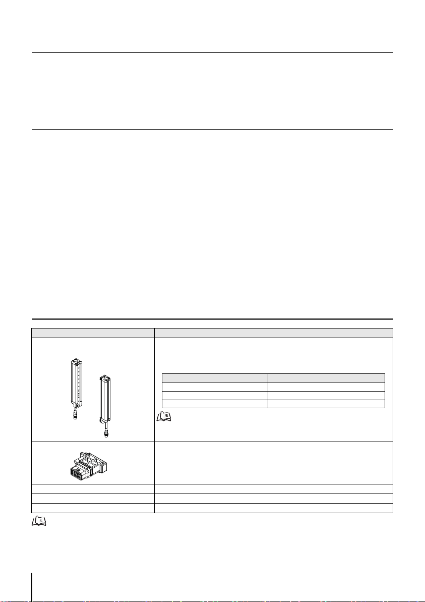
1. 同梱物のご確認
セーフ テ ィ ラ イ トカ ーテン
形F3SG-4RA□□□□-25-02TS本体
終端キ ャ ップ(外部テ ス ト 入力機能切 り 替え 用)
トラブルシューティングステッカ 1
安全上のご注意 1
クイックインストールマニュアル 1
定格/性能、 入出力回路、 LED表示灯の点灯パ タ ー ン、 ト ラ ブル シ ューテ ィ ングについては、 ユーザーズ マニ ュアル を参照し て
ください。
1
製品 数量
投光器×1、 受光器×1
詳細につ いては F3SG-4RA-25-02TS
ださい。
1
シリーズユーザーズマニュアル
F3SG-4RA□□□□-25-02TS
クイックインストールマニュアル
を参照して く
Page 3
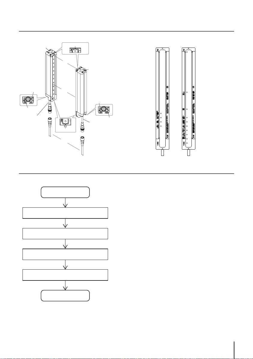
2. 各部の名称
㟁※䜿䞊䝤䝹
㻔⅊㻕
㟁※䜿䞊䝤䝹
㻔㯮㻕
ග㍈
⾲♧ⅉ
ᘏ㛗䜿䞊䝤䝹
⤊➃䜻䝱䝑䝥
⤊➃䜻䝱䝑䝥
ග㍈䝉䞁䝍䞊䝷䜲䞁䝬䞊䜽
䝻䞊䝍䝸䞊㻿㼃
ᶵ⬟᥋ᆅ➃Ꮚ
ග㍈䝉䞁䝍䞊䝷䜲䞁䝬䞊䜽
䝻䞊䝍䝸䞊㻿㼃
ᶵ⬟᥋ᆅ➃Ꮚ
ᢞගჾ
ཷගჾ
䠘ᢞගჾ䠚
䠘ཷගჾ䠚
㻝㻚䚷ᢞගṆ୰⾲♧ⅉ㻔⥳㻕
㻞㻚䚷䝻䞁䜾⾲♧ⅉ㻔⥳㻕
㻟㻚䚷㟁※⾲♧ⅉ㻔⥳㻕
㻠㻚䚷䜶䝷䞊⾲♧ⅉ㻔㉥㻕
㻝㻚䚷㼀㻻㻼⾲♧ⅉ㻔㟷㻕
㻞㻚䚷㻺㻼㻺タᐃ⾲♧ⅉ㻔⥳㻕
㻟㻚䚷ᵓᡂ⾲♧ⅉ㻔⥳㻕
㻠㻚䚷እ㒊䝸䝺䞊䝰䝙䝍⾲♧ⅉ㻔⥳㻕
㻣㻚䚷Ᏻᐃධග⾲♧ⅉ㻔⥳㻕
㻡㻚䚷ෆ㒊␗ᖖ㻛䝜䜲䝈⾲♧ⅉ㻔㉥㻕
㻤㻚䚷ฟຊ⾲♧ⅉ㻔⥳㻛㉥㻕
㻢㻚䚷䜶䝷䞊⾲♧ⅉ㻔㉥㻕
㻥㻚䚷ྠᮇ⾲♧ⅉ㻔⥳㻕
㻝㻜㻚䚷㻮㼀㻹⾲♧ⅉ㻔㟷㻕
䝉䝑䝖䜰䝑䝥
䝻䞊䝍䝸䞊 㻿㼃
設定・終端キャップによる機能
㻖
㓄⥺
ྲྀ䜚䛴䛡 䞉 ග㍈ㄪᩚ
ືస䝏䜵䝑䜽
䛚䜟䜚
. . . . 3 ページ
. . . . 4 ページ
. . . . 5 ページ
. . . .12 ページ
3. ラ イ ト カー テン セ ッ ト ア ッ プ手順例
* ロー タ リー SW ・ 終端キ ャ ッ プに よ る機能の設定は必要に応 じ て 実施 し て く だ さ い。
F3SG-4RA□□□□-25-02TS
クイックインストールマニュアル
2
Page 4
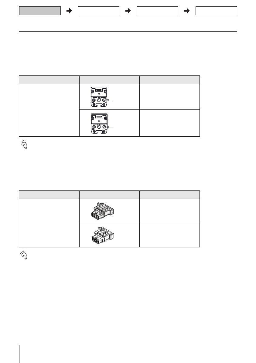
4. ロー タ リ ー SW ・ 終端キャ ッ プ設定
䝻䞊䝍䝸䞊㻿㼃
䝻䞊䝍䝸䞊㻿㼃
ྲྀ䜚䛴䛡 䞉 ග㍈ㄪᩚ
㓄⥺
䝻䞊䝍䝸䞊 㻿㼃 䞉 ⤊➃䜻䝱䝑䝥タᐃ
ືస䝏䜵䝑䜽
4-1. ロー タ リ ー SW での機能切 り替え
本体の電源ケー ブル側に、 機能設定 を行 う ための ロー タ リー SW があり ま す。 F3SG-R を 設置す る前に事前
にロー タ リー SW の設定 を行っ て く だ さ い。
ロー タ リ ー SW の設定完了後に電源を入れ て く ださ い。
連結し た セ ンサはプ ラ イ マ リ センサのロ ー タ リ ー SW 設定に基いて動作し ま す。 セ カ ン ダ リセンサの ロー
タ リー SW 設定は動作に影響し ま せん。
機能 設定 概要
スキ ャ ンコ ード A (出荷時設定)
スキャ ンコー ド切 り替え
スキャ ンコー ドB
・ ロー タ リ ー SWの操作はF3SG-Rの電源投入前に行 っ て く ださ い。
・ 投光器およ び受光器の両方を 同 じ コー ドに 設定する 必要があ りま す。
・ ロー タ リ ー SWの設定変更は電源投入後、 も し く はロ ッ クア ウ ト リセ ッ ト 後に反映 さ れま す。
・ F3SG-R動作中にロ ー タ リー SWを操作 した場合、 F3SG-Rはロ ッ クア ウ ト しま す。
4-2. 終端キ ャ ッ プでの機能切り 替え
投光器の電源ケー ブル側と 反対側に、 機能設定 を行 う ための終端キャ ッ プが取 り付け ら れてい ます。
F3SG-R を設置する前に事前に外部テス ト入力機能の設定を 行 っ て く ださ い。 終端キ ャ ッ プは電源を切 っ た
状態で交換し て く ださ い。
機能 設定 概要
外部テ ス ト 入力機能切り替え
・ 終端キャ ッ プ に装着 さ れて いる 絶縁ゴ ムを はず さ ないで く ださ い。 保護機能の劣化につ なが り ます。
・ 終端キャ ッ プ を装着する 際は、 ネ ジ(M2.5) を確実に締めて く だ さ い。 (推奨 トルク 0.35N ・ m) 脱落およ び保護機能の劣化に つ
ながり ます。
・ 終端キャ ッ プ を 脱着する と コネ ク タ部の絶縁ゴ ムがはずれ る場合があ り ます。 コ ネク タの溝部 に絶縁ゴ ムを はめ直 し 、 コ ネ
クタをセンサにつけ直してください。
3
㯮Ⰽ
ⓑⰍ
24Vア クテ ィ ブ (出荷時設定)
0Vア クテ ィ ブ
F3SG-4RA□□□□-25-02TS
クイックインストールマニュアル
Page 5
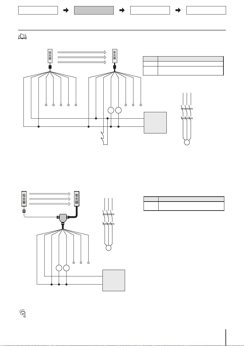
5. 配線例
㻷㻹㻝㻘㻷㻹㻞㻦ᙉไ䜺䜲䝗᥋Ⅼ䛝䝉䞊䝣䝔䜱䝸䝺䞊㻔ᙧ㻳㻣㻿㻭㻕
㻹㻦୕┦䝰䞊䝍
㻗㻞㻠㻌㼂㻰㻯
㻜㻌㼂㻰㻯
㟁※
ᮍ⏝㻔᱈䠅
ᮍ⏝㻔㉥䠅㻖㻟
ᮍ⏝㻔ⓑ䠅㻖㻟
ᮍ⏝㻔㯤䠅㻖㻟
䝔䝇䝖ධຊ䠄㯮䠅㻖㻝
ᮍ⏝㻔⅊䠅
㻞㻠㼂㻔Ⲕ䠅
㻞㻠㼂㻔Ⲕ䠅
እ㒊䝸䝺䞊䝰䝙䝍ධຊ䠄㉥䠅㻖㻞
ไᚚฟຊ㻝䠄㯮䠅
ไᚚฟຊ㻞䠄ⓑ䠅
⿵ຓฟຊ㻔㯤㻕
㻼㻯㏻ಙ⥺䠄䠇䠅䠄⅊䠅
㻼㻯㏻ಙ⥺䠄䠉䠅䠄᱈䠅
㻜㼂䠄
㟷䠅
㻜㼂䠄
㟷䠅
ᢞගჾ
ཷගჾ
ᙧ㻲㻟㻥㻙㻶㻰䕕䕕㻭㻙㻸㻌㻖㻠 ᙧ㻲㻟㻥㻙㻶㻰䕕䕕㻭㻙㻰㻌㻖㻠
㻷㻹㻝
㻷㻹㻞
㻹
㻷㻹㻝
㻷㻹㻞
㻷㻹㻝
㻷㻹㻞
*1. 外部テ ス ト機能を 使用する 場合は、 テス ト スイ ッ チ(a接点) を介 して24Vへ接続し て く だ さ い。
*2. ロ ッ ク アウ ト リ セッ ト 機能を使用 する 場合は、 ロ ッ クア ウ ト リセ ッ ト ス イッ チ(b接点) を 外部 リレ ーモニ タ入力にKM1/
KM2接点と直列 に接続 し て く ださ い。
*3. 形F39-JD□RA-L投光器用片側コ ネク タケーブル(耐油ケ ーブ ル)の場合は、 赤色 ・ 白色 ・ 黄色のケー ブル芯線は出 てい ませ
ん。
*4. 形F39-JD□A-□片側コ ネク タ ケーブルを使用す る場合は、 シ ール ド 線を 0Vへ接続 し て く ださ い。
[ 各機能の設定 ]
機能
受光器 外部 リ レーモ ニ タ
投光器
外部テ ス ト : 24Vア クテ ィ ブ(終端キ ャ ッ
プ : 黒色) (出荷時設定)
*1. 外部テ ス ト 機能を 使用する場合は、 テス ト ス イ ッチ (a接点)を 介し て24Vへ接続 し て く だ さ い。
*2. 形F39-JD□A-□片側コ ネク タ ケー ブル を使用す る場合は、 シ ール ド 線を 0Vへ接続 し て く ださい。
[ 各機能の設定 ]
機能
投光器
外部テ ス ト : 24Vアク テ ィ ブ(終端 キャ ッ
プ : 黒色) (出荷時設定)
省配線用ケー ブル (形F39-JD□BA) と 省配線コ ネク タ (形F39-CN5) と を組み合わせて配線す る こと で、 省配線 コネ ク タシ ス
テムと し て使用できます。
ྲྀ䜚䛴䛡 䞉 ග㍈ㄪᩚ
㓄⥺
䝻䞊䝍䝸䞊 㻿㼃 䞉 ⤊➃䜻䝱䝑䝥タᐃ
ືస䝏䜵䝑䜽
入出力回路および下記以外の配線例につい ては、 ユーザーズマ ニ ュ アル を参照 して く だ さ い。
5-1. EDM 使用、 外部テス ト 24V ア ク テ ィ ブ未使用
5-2. 省配線コ ネ ク タ使用、 外部テ ス ト 24V ア ク テ ィ ブ未使用
ᙧ㻲㻟㻥㻙㻯㻺㻡
ᙧ㻲㻟㻥㻙㻶㻰䕕㻮㻙㻸
㟷䠅
㻜㼂䠄
㻞㻠㼂㻔Ⲕ䠅
省配線用ケー ブル(形F39-JD□BA) と省配線 コ ネ ク タ(形F39-CN5)かん合時の保護構造(IEC60529 )はIP67等級に な りま す。
使用する 際には切削油がかか らないよ う 保護し て く だ さ い。
F3SG-4RA□□□□-25-02TS
クイックインストールマニュアル
ᙧ㻲㻟㻥㻙㻶㻰䕕㻭㻙㻰㻌㻖㻞
䝔䝇䝖ධຊ䠄㉥䠅㻌㻖㻝
ไᚚฟຊ㻝䠄㯮䠅
ไᚚฟຊ㻞䠄ⓑ䠅
㻷㻹㻝 㻷㻹㻞
ᮍ⏝㻔㯤㻕
㻷㻹㻝
㻷㻹㻞
㻹
㻼㻯㏻ಙ⥺䠄䠇䠅䠄⅊䠅
㻷㻹㻝㻘㻷㻹㻞㻦ᙉไ䜺䜲䝗᥋Ⅼ䛝䝉䞊䝣䝔䜱䝸䝺䞊㻔ᙧ㻳㻣㻿㻭㻕
㻼㻯㏻ಙ⥺䠄䠉䠅䠄᱈䠅
㻹㻦୕┦䝰䞊䝍
㻗㻞㻠㻌㼂㻰㻯
㻜㻌㼂㻰㻯
㟁※
4
Page 6
6. 取 り つけ ・ 光軸調整
㻌㻟㻝㻚㻠㻌
㻌㻠㻢㻚㻟㻡㻌
㻌㻝㻜㻌㻌㻝㻜㻌
㻌㻼㻌
㻌㻰㻌
㻌㻯䠄᳨ฟᖜ䠅㻌
㻌㻝㻡㻜௨ୗ㻌㻌㻝㻡㻜௨ୗ㻌 㻌㻲㻌
㻌㻡㻢㻚㻡㻌
㻌㻡㻢㻚㻡㻌
㻌㻝㻡㻜௨ୗ㻌
㻌㻲㻌
㻌㻝㻡㻜௨ୗ㻌
㻌㻯㻌
㻌㻟㻚㻥㻡㻌
㻞㻙㻹㻠
㻞㻙㻹㻠
㻞㻙㻹㻡㻌䜎䛯䛿
㻹㻢
䠘㻹㻡䜎䛯䛿㻹㻢ᅛᐃ䠚
㻞㻙㻹㻡㻌䜎䛯䛿
㻹㻢
㻌㻟㻤㻌
䝣䝸䞊䝻䜿䞊䝅䝵䞁㔠ල
㻔ᙧ㻲㻟㻥㻙㻸㻳㻾㻭㻕
䝣䝸䞊䝻䜿䞊䝅䝵䞁㔠ල
㻔ᙧ㻲㻟㻥㻙㻸㻳㻾㻭㻕
㻌㻞㻢㻚㻟㻌
㻌㻣㻟㻌
㻌㻢㻚㻟㻌
㻌㻟㻚㻥㻡㻌
㻌㻡㻢㻚㻡㻌
㻌㻡㻜㻌
[ 単位 : mm ]
[ 背面取り つけ時 ]
*1. セン サ片側(投光器ま たは受光器)の取 り つけに必要な数量です 。
*2. 検出幅が0240の場合、 セン サ片側につき 1個で も取 り つけ可能 です。 こ の場合、 寸法Cの2分の1の位置 (セ ンサ縦方向の中央)
に本金具を 取 り つけ て く ださ い。
側面取 り つけ時の外形寸法図につい ては、 ユーザーズマ ニ ュ アル を参照 して く ださ い。
寸法C 形式中の4桁の数字 (検出幅)
寸法D C-20
寸法P
20
検出幅(C) フ リー ロ ケーシ ョ ン金具の数 *1 寸法F
0240~1200 2 *2 1000mm以下
1280~1920 3 1000mm以下
ྲྀ䜚䛴䛡
⨨☜ㄆ
㻿㼠㼑㼜㻝
ྲྀ䜚䛴䛡
㻿㼠㼑㼜㻞
ග㍈ㄪᩚ
㻿㼠㼑㼜㻟
ྲྀ䜚䛴䛡 䞉 ග㍈ㄪᩚ
㓄⥺
䝻䞊䝍䝸䞊 㻿㼃 䞉 ⤊➃䜻䝱䝑䝥タᐃ
ືస䝏䜵䝑䜽
6-1. フ リー ロ ケーシ ョ ン金具 ( 形 F39-LGRA) を取 り つける場合
■外形寸法図 (取 り つけ位置確認)
F3SG-4RA□□□□-25-02TS
クイックインストールマニュアル
5
Page 7
■取り つけ方法
㻨⫼㠃ྲྀ䜚䛴䛡㻪
㻨ഃ㠃ྲྀ䜚䛴䛡㻪
㻹㻡㻛㻹㻢
㻹㻡㻛㻹㻢
ᮏయᅛᐃ⏝䝪䝹䝖
ග㍈ㄪᩚ⏝䝪䝹䝖
㻔භゅ✰䝪䝹䝖㻔㻹㻠㽢㻞㻞㻕㻕
ග㍈ㄪᩚ⏝䝪䝹䝖
㻔භゅ✰䝪䝹䝖㻔㻹㻠㽢㻞㻞㻕㻕
ᮏయᅛᐃ⏝䝪䝹䝖
ᮏయᅛᐃ⏝䝪䝹䝖
ග㍈ㄪᩚ⏝䝪䝹䝖
䠘ཷගჾ䠚
㻾㻱㻯㻱㻵㼂㻱㻾
㻔ཷගჾ㻕
㼀㻻㻼㻔㟷㻕
㻿㼀㻮㻔⥳㻕
㻮㼀㻹㻔㟷㻕
ᮏయᅛᐃ⏝䝪䝹䝖
ග㍈ㄪᩚ⏝䝪䝹䝖
㻔භゅ✰䝪䝹䝖㻔㻹㻠㽢㻞㻞㻕㻕
ග㍈ㄪᩚ⏝䝪䝹䝖
㻔භゅ✰䝪䝹䝖㻔㻹㻠㽢㻞㻞㻕㻕
ᮏయᅛᐃ⏝䝪䝹䝖
ྲྀ䜚䛴䛡 䞉 ග㍈ㄪᩚ
㓄⥺
䝻䞊䝍䝸䞊 㻿㼃 䞉 ⤊➃䜻䝱䝑䝥タᐃ
ືస䝏䜵䝑䜽
1. 金具を 壁面に取り つけま す。
㻿㼠㼑㼜㻝
ྲྀ䜚䛴䛡
⨨☜ㄆ
㻿㼠㼑㼜㻞
ྲྀ䜚䛴䛡
壁面への取 り つけネジは付属し ていません。
2. 本体固定用ボル ト を 緩め、 本体 をはめて く ださ い。
ᮏయᅛᐃ⏝䝪䝹䝖
㻔භゅ✰䝪䝹䝖㻔㻹㻠㽢㻞㻞㻕㻕
㔠ල㻔㻞㻕
㔠ල㻔㻝㻕
3. 本体固定用ボル ト を 固定 し ( 締め付け ト ルク : 3.0N ・ m)、 光軸調整用ボル ト を 緩めます。
4. 表示灯を 参考に光軸を 調整 し 、 光軸調整ボル ト を固定し ま す。 ( 締め付け ト ル ク : 3.0N ・ m)
㻿㼠㼑㼜㻟
ග㍈ㄪᩚ
フ リー ロケーシ ョ ン金具の角度調整範囲は±15°で す。
F3SG-4RA□□□□-25-02TS
クイックインストールマニュアル
6
Page 8
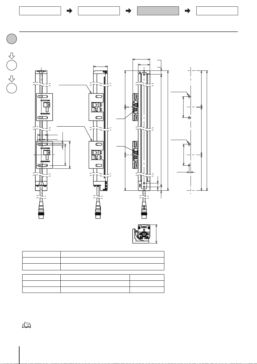
6-2. 上下取付金具 ( 形 F39-LGRTB) を 取 り つけ る 場合
[ 単位 : mm ]
[ 背面取り つけ時 ]
側面取 り つけ時の外形寸法図につい ては、 ユーザーズマ ニ ュ アル を参照 して く ださ い。
* セ ンサ片側(投光器 また は受光器)の取 り つけに必要な数量です。
寸法C 形式中の4桁の数字 (検出幅)
寸法D C-20
寸法G C+27.2+N1+N2
寸法H C+38+N1+N2
寸法I C+58+N1+N2
寸法N1 0~30
寸法N2 0~13
寸法P 20
検出幅(C) 上下取付金具の数 * 中間取付金具の数 * 寸法F
0240~1040 2 0 1120~1920 2 1 1000mm以下
ྲྀ䜚䛴䛡
⨨☜ㄆ
㻿㼠㼑㼜㻝
ྲྀ䜚䛴䛡
㻿㼠㼑㼜㻞
ග㍈ㄪᩚ
㻿㼠㼑㼜㻟
ྲྀ䜚䛴䛡 䞉 ග㍈ㄪᩚ
㓄⥺
䝻䞊䝍䝸䞊 㻿㼃 䞉 ⤊➃䜻䝱䝑䝥タᐃ
ືస䝏䜵䝑䜽
■外形寸法図 (取 り つけ位置確認)
㻌㻟㻝㻚㻠㻌
㻌㻝㻥㻌
㻌㻲㻌
㻌㻣㻚㻡㻌
㻌㻺㻝㻌
㻌㻡㻚㻡㻌
ୖୗྲྀ㔠ල
㻔ᙧ㻲㻟㻥㻙㻸㻳㻾㼀㻮㻕
⫼㠃㻦㻞㻙㻹㻠
୰㛫ྲྀ㔠ල
㻔ᙧ㻲㻟㻥㻙㻸㻳㻾㻭㻕
㻌㻞㻢㻚㻟㻌
㻌㻟㻚㻥㻡㻌
㻌㻝㻞㻌
㻌㻟㻌
㻌㻟㻤㻌
㻞㻙㻹㻡㻌䜎䛯䛿
㻹㻢
㻌㻝㻥㻌
㻠㻙㻹㻡
㻌㻲㻌
㻞㻙㻹㻡㻌䜎䛯䛿
㻹㻢
㻞㻙㻹㻤
㻌㻲㻌
䃥㻥
㻌㻝㻜㻌㻌㻝㻜㻌
㻌㻵㻌
㻌㻴㻌
㻌㻣㻟㻌
㻌㻡㻢㻚㻡㻌
㻌㻢㻚㻟㻌
ୖୗྲྀ㔠ල
㻔ᙧ㻲㻟㻥㻙㻸㻳㻾㼀㻮㻕
㻌㻳㻌
㻞㻙㻹㻠
㻌㻼㻌
㻌㻺㻞㻌
㻌㻠㻢㻚㻟㻡㻌
㻞㻙㻹㻠
㻌㻡㻜㻌
7
㻌㻰㻌
㻌㻯䠄᳨ฟᖜ䠅㻌
㻌㻟㻚㻥㻡㻌
䠘ୖୗྲྀ㔠ල䛾㻹㻡ᅛᐃ䠚 䠘ୖୗྲྀ㔠ල䛾㻹㻤ᅛᐃ䠚
㻌㻡㻢㻚㻡㻌
㻌㻝㻥㻌
㻌㻯㻌
㻌㻳㻌
㻌㻟㻚㻥㻡㻌
F3SG-4RA□□□□-25-02TS
㻌㻴㻌
㻌㻯㻌
㻌㻡㻢㻚㻡㻌
クイックインストールマニュアル
Page 9

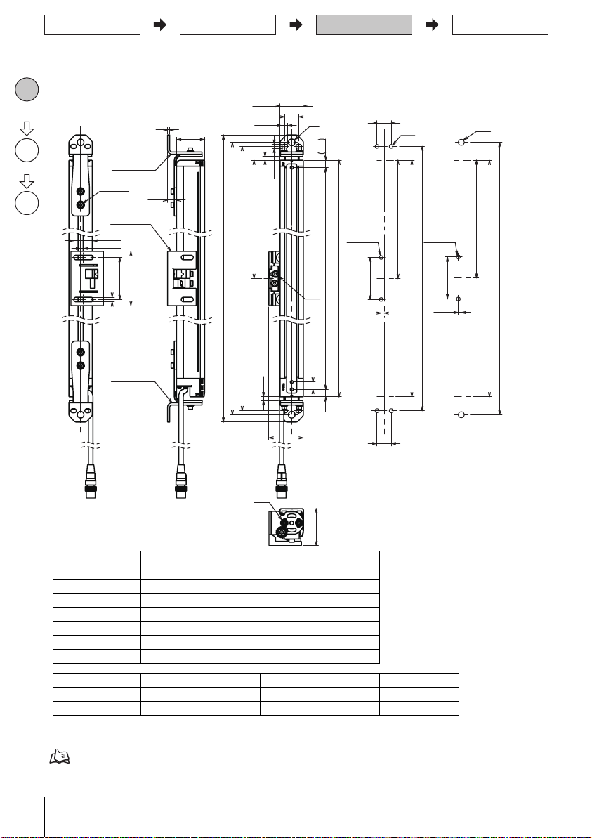
6-3. 上下取付金具 ( 形 F39-LGRTB-2) を取 り つける場合
㻌㻝㻜㻌㻌㻝㻜㻌
㻌㻼㻌
㻌㻰㻌
㻌㻯䠄᳨ฟᖜ䠅㻌
㻌㻺㻝㻌
㻌㻺㻞㻌
㻌㻠㻢㻚㻟㻡㻌
㻌㻵㻌
㻌㻶㻌
㻌㻞㻟㻚㻡㻌
㻌㻞㻠㻚㻡㻌
㻌㻟㻞㻌
㻌㻟㻝㻚㻠㻌
㻌㻡㻚㻡㻌
㻌㻢㻚㻡㻌
㻌㻡㻢㻚㻡㻌
㻌㻯㻌
㻌㻟㻚㻥㻡㻌
㻌㻲㻌
㻌㻲㻌
㻌㻞㻜㻌
㻌㻞㻜㻌
㻌㻴㻌
㻌㻡㻢㻚㻡㻌
㻌㻯㻌
㻌㻟㻚㻥㻡㻌
㻌㻲㻌
㻌㻵㻌
㻌㻳㻌
㻌㻴㻌
㻌㻞㻜㻌
㻌㻳㻌
㻞㻙㻹㻠
㻞㻙㻹㻡㻌䜎䛯䛿
㻹㻢
䃥㻥
䠘ୖୗྲྀ㔠ල䛾㻹㻡ᅛᐃ䠚 䠘ୖୗྲྀ㔠ල䛾㻹㻢ᅛᐃ
䚷䚷䚷䚷䚷䚷䚷䚷䜎䛯䛿䚷㻹㻤ᅛᐃ䠚
㻠㻙㻹㻡
㻞㻙㻹㻡㻌䜎䛯䛿
㻹㻢
㻞㻙㻹㻤
㻞㻙㻹㻢
㻌㻡㻜㻌
㻞㻙㻹㻠
㻌㻟㻤㻌
㻌㻟㻌
㻌㻝㻞㻌
ୖୗྲྀ㔠ල
㻔ᙧ㻲㻟㻥㻙㻸㻳㻾㼀㻮㻙㻞㻕
୰㛫ྲྀ㔠ල
㻔ᙧ㻲㻟㻥㻙㻸㻳㻾㻭㻕
ୖୗྲྀ㔠ල
㻔ᙧ㻲㻟㻥㻙㻸㻳㻾㼀㻮㻙㻞㻕
㻌㻞㻢㻚㻟㻌
㻌㻣㻟㻌
㻌㻢㻚㻟㻌
㻌㻟㻚㻥㻡㻌
㻌㻡㻢㻚㻡㻌
⫼㠃㻦㻞㻙㻹㻠
[ 単位 : mm ]
[ 背面取り つけ時 ]
側面取 り つけ時の外形寸法図につい ては、 ユーザーズマ ニ ュ アル を参照 して く ださ い。
* セ ンサ片側(投光器 また は受光器)の取 り つけに必要な数量です。
寸法C 形式中の4桁の数字 (検出幅)
寸法D C-20
寸法G C+51+N1+N2
寸法H C+54+N1+N2
寸法I C+88+N1+N2
寸法J C+106+N1+N2
寸法N1 0~30
寸法N2 0~13
寸法P
20
検出幅(C) 上下取付金具の数 * 中間取付金具の数 * 寸法F
0240~1040 2 0 1120~1920 2 1 1000mm以下
ྲྀ䜚䛴䛡 䞉 ග㍈ㄪᩚ
㓄⥺
䝻䞊䝍䝸䞊 㻿㼃 䞉 ⤊➃䜻䝱䝑䝥タᐃ
ືస䝏䜵䝑䜽
■外形寸法図 (取 り つけ位置確認)
㻿㼠㼑㼜㻝
ྲྀ䜚䛴䛡
⨨☜ㄆ
㻿㼠㼑㼜㻞
ྲྀ䜚䛴䛡
㻿㼠㼑㼜㻟
ග㍈ㄪᩚ
F3SG-4RA□□□□-25-02TS
クイックインストールマニュアル
8
Page 10

6-4. 上下取付金具 ( 形 F39-LGRTB-3) を取 り つける場合
㻌㻟㻝㻚㻠㻌
㻌㻝㻜㻌㻌㻝㻜㻌
㻌㻼㻌
㻌㻰㻌
㻌㻯䠄᳨ฟᖜ䠅㻌
㻌㻺㻝㻌
㻌㻺㻞㻌
㻌㻠㻢㻚㻟㻡㻌
㻌㻵㻌
㻌㻟㻡㻌
㻌㻞㻟㻚㻞㻌
㻌㻞㻢㻚㻡㻌
㻌㻢㻚㻡㻌
㻌㻤㻚㻞㻌
㻌㻡㻢㻚㻡㻌
㻌㻯㻌
㻌㻟㻚㻥㻡㻌
㻌㻲㻌
㻌㻲㻌
㻌㻳㻌
㻌㻝㻥㻌
㻌㻳㻌
㻌㻡㻢㻚㻡㻌
㻌㻯㻌
㻌㻟㻚㻥㻡㻌
㻌㻲㻌
㻌㻴㻌
㻌㻴㻌
㻞㻙㻹㻠
㻞㻙㻹㻡㻌䜎䛯䛿
㻹㻢
䠘ୖୗྲྀ㔠ල䛾
䚷䚷䚷䚷䚷㻹㻡䜎䛯䛿㻹㻢ᅛᐃ䠚
䠘ୖୗྲྀ㔠ල䛾㻹㻤ᅛᐃ䠚
㻞㻙㻹㻡䜎䛯䛿㻹㻢
㻞㻙㻹㻡㻌䜎䛯䛿
㻹㻢
㻞㻙㻹㻤
㻌㻡㻜㻌
㻞㻙㻹㻠
㻌㻟㻤㻌
㻌㻠㻌
୰㛫ྲྀ㔠ල
㻔ᙧ㻲㻟㻥㻙㻸㻳㻾㻭㻕
ୖୗྲྀ㔠ල
㻔ᙧ㻲㻟㻥㻙㻸㻳㻾㼀㻮㻙㻟㻕
ୖୗྲྀ㔠ල
㻔ᙧ㻲㻟㻥㻙㻸㻳㻾㼀㻮㻙㻟㻕
㻌㻞㻢㻚㻟㻌
㻌㻣㻟㻌
㻌㻢㻚㻟㻌
㻌㻟㻚㻥㻡㻌
㻌㻡㻢㻚㻡㻌
⫼㠃㻦㻞㻙㻹㻠
[ 単位 : mm ]
[ 背面取り つけ時 ]
側面取 り つけ時の外形寸法図につい ては、 ユーザーズマ ニ ュ アル を参照 して く ださ い。
* セ ンサ片側(投光器 また は受光器)の取 り つけ に必要な 数量です 。
寸法C 形式中の4桁の数字 (検出幅)
寸法D C-20
寸法G C+39.5+N1+N2
寸法H C+65+N1+N2
寸法I C+84+N1+N2
寸法N1 0~30
寸法N2 0~13
寸法P
20
検出幅(C) 上下取付金具の数 * 中間取付金具の数 * 寸法F
0240~1040 2 0 1120~1920 2 1 1000mm以下
ྲྀ䜚䛴䛡
⨨☜ㄆ
㻿㼠㼑㼜㻝
ྲྀ䜚䛴䛡
㻿㼠㼑㼜㻞
ග㍈ㄪᩚ
㻿㼠㼑㼜㻟
ྲྀ䜚䛴䛡 䞉 ග㍈ㄪᩚ
㓄⥺
䝻䞊䝍䝸䞊 㻿㼃 䞉 ⤊➃䜻䝱䝑䝥タᐃ
ືస䝏䜵䝑䜽
■外形寸法図 (取 り つけ位置確認)
9
F3SG-4RA□□□□-25-02TS
クイックインストールマニュアル
Page 11

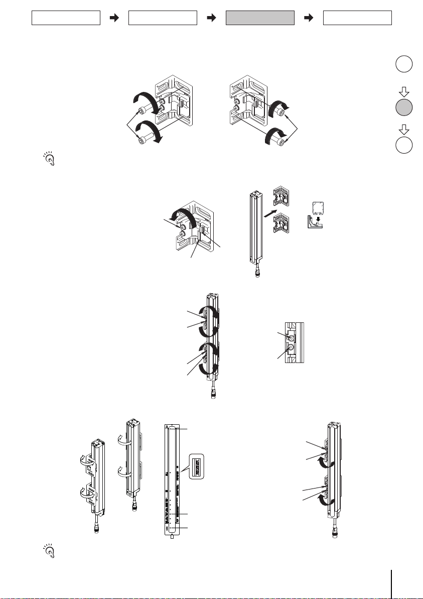
■取 り つけ方法 と光軸調整
ᮏయᅛᐃ⏝䝪䝹䝖
㻔භゅ✰䝪䝹䝖㻔㻹㻠㽢㻞㻞㻕㻕
㔠ල㻔㻞㻕
㔠ල㻔㻝㻕
ྲྀ䜚䛴䛡 䞉 ග㍈ㄪᩚ
㓄⥺
䝻䞊䝍䝸䞊 㻿㼃 䞉 ⤊➃䜻䝱䝑䝥タᐃ
ືస䝏䜵䝑䜽
1. 光軸調整用ボル ト を 緩め角度 を調整 し、 上下金具 (2) の本体固定用ボル ト を緩め ます。
ග㍈ㄪᩚ⏝䝪䝹䝖
㻔භゅ✰䝪䝹䝖㻔㻹㻠㽢㻣㻕㻕
䠘⫼㠃ྲྀ䜚䛴䛡䠚
(2)
ග㍈ㄪᩚ⏝䝪䝹䝖
㻔භゅ✰䝪䝹䝖㻔㻹㻠㽢㻣㻕㻕
䠘ഃ㠃ྲྀ䜚䛴䛡䠚
(2)
㻔භゅ✰䝪䝹䝖㻔㻹㻠㽢㻣㻕㻕
ᮏయᅛᐃ⏝䝪䝹䝖
㻿㼠㼑㼜㻝
ྲྀ䜚䛴䛡
⨨☜ㄆ
(1)
ୖୗ㔠ල㻔㻟㻕
ୖୗ㔠ල㻔㻝㻕
ୖୗ㔠ල㻔㻞㻕
(1)
ୖୗ㔠ල㻔㻟㻕
ୖୗ㔠ල㻔㻝㻕
ୖୗ㔠ල㻔㻞㻕
ୖୗ㔠ල㻔㻟㻕
ୖୗ㔠ල㻔㻞㻕
2. F3SG-R の筐体 ( 黄色のエ リ ア ) 内に上下金具 (1) の全体が位置する よ う に固定 し て く だ さ い。
( 推奨締め付け ト ルク : 3.0N ・ m)
䠘⫼㠃ྲྀ䜚䛴䛡䠚
ᮏయᅛᐃ⏝䝪䝹䝖
䠘ഃ㠃ྲྀ䜚䛴䛡䠚
ᮏయᅛᐃ⏝䝪䝹䝖
3. 中間取付金具を 壁面に固定し ま す。 ( 中間取付金具使用時のみ )
㻨⫼㠃ྲྀ䜚䛴䛡㻪
㻹㻡㻛㻹㻢
側面への取付ネジは付属 し て いま せん。
㻨ഃ㠃ྲྀ䜚䛴䛡㻪
㻹㻡㻛㻹㻢
(3)
㻿㼠㼑㼜㻞
ྲྀ䜚䛴䛡
㻿㼠㼑㼜㻟
ග㍈ㄪᩚ
4. 本体固定用ボル ト を 緩め、 本体 をはめて く ださ い。 ( 中間取付金具使用時のみ )
F3SG-4RA□□□□-25-02TS
クイックインストールマニュアル
10
Page 12

5. 本体固定用ボル ト を 固定 し ( 締め付け ト ルク : 3.0N ・ m)、 光軸調整用ボル ト を 緩めます。
㻨⫼㠃ྲྀ䜚䛴䛡㻪
㻹㻡㻛㻹㻢
㻨ഃ㠃ྲྀ䜚䛴䛡㻪
㻹㻡㻛㻹㻢
ග㍈ㄪᩚ⏝䝪䝹䝖
㻔ୖୗྲྀ㔠ල㻕
ග㍈ㄪᩚ⏝䝪䝹䝖
㻔୰㛫ྲྀ㔠ල㻕
ග㍈ㄪᩚ⏝䝪䝹䝖
㻔ୖୗྲྀ㔠ල㻕
ྲྀ䜚䛴䛡
⨨☜ㄆ
㻿㼠㼑㼜㻝
ྲྀ䜚䛴䛡
㻿㼠㼑㼜㻞
ග㍈ㄪᩚ
㻿㼠㼑㼜㻟
ྲྀ䜚䛴䛡 䞉 ග㍈ㄪᩚ
㓄⥺
䝻䞊䝍䝸䞊 㻿㼃 䞉 ⤊➃䜻䝱䝑䝥タᐃ
ືస䝏䜵䝑䜽
( 中間取付金具使用時のみ )
ᮏయᅛᐃ⏝䝪䝹䝖
ග㍈ㄪᩚ⏝䝪䝹䝖
6. 上下取付金具を 壁面に固定し ま す。
壁面への取 り つけネジは付属し ていません。
ᮏయᅛᐃ⏝䝪䝹䝖
ග㍈ㄪᩚ⏝䝪䝹䝖
㻔භゅ✰䝪䝹䝖㻔㻹㻠㽢㻞㻞㻕㻕
(1)
(2)
7. 表示灯を 参考に光軸を 調整 し 、 光軸調整ボル ト を固定し ま す。 ( 締め付け ト ル ク : 3.0N ・ m)
11
上下取付金具のみの場合、 角度調整範囲は±22.5°で す。
中間取付金具を 併用する場合、 角度調整範囲は±15°に な りま す。
䠘ཷගჾ䠚
㼀㻻㻼㻔㟷㻕
㻾㻱㻯㻱㻵㼂㻱㻾
㻔ཷගჾ㻕
㻿㼀㻮㻔⥳㻕
㻮㼀㻹㻔㟷㻕
F3SG-4RA□□□□-25-02TS
クイックインストールマニュアル
Page 13

7. 動作チ ェ ッ ク
http://www.ia.omron.com/f3sg-r
ト ラ ブルシューテ ィ ング方法については、 ユーザーズマニュ アルまたはウェ ブサイ
ト も参照 し て く ださ い。
インダ ストリア ルオートメー ションビ ジネ スカン パ ニー
●その他のお問い合わせ
納期・価格・サンプル・仕様書は貴社のお取引先、または貴社担当オムロン販売員にご相談ください。
オムロン制御機器販売店やオムロン販売拠点は、Webページでご案内しています。
●製品に関するお問い合わせ先
クイック オムロン
0120-919-066
■営業時間:8:00〜21:00 ■営業日:365日
●FAXやWebページでもお問い合わせいただけます。
携帯電話・PHS・IP電話などではご利用いただけませんので、下記の電話番号へおかけくださ い 。
電話
055-982-5015
(通話料がかかります)
お客様相談室
FAX055-982-5051/www.fa.omron.co.jp
当社商品は、一般工業製品向けの汎用品として設計製造されています。従いまして、次に掲げる用途での使用を意図しておらず、お客様
が当社商品をこれらの用途に使用される際には、当社は当社商品に対して一切保証をいたしません。ただし、次に掲げる用途であっても
当社の意図した特別な商品用途の場合や特別の合意がある場合は除きます。
(a)高い安全性が必要とされる用途(例:原子力制御設備、燃焼設備、航空・宇宙設備、鉄道設備、昇降設備、娯楽設備、医用機器、安
全装置、その他生命・身体に危険が及びうる用途)
(b)高い信頼性が必要な用途(例:ガス・水道・電気等の供給システム、24 時間連続運転システム、決済システムほか権利・財産を取扱
う用途など)
(c)厳しい条件または環境での用途(例:屋外に設置する設備、化学的汚染を被る設備、電磁的妨害を被る設備、振動・衝撃を受ける設備など)
(d)カタログ等に記載のない条件や環境での用途
*(a) から (d) に記載されている他、本カタログ等記載の商品は自動車(二輪車含む。以下同じ)向けではありません。自動車に搭載する
用途には利用しないで下さい。自動車搭載用商品については当社営業担当者にご相談ください。
*上記は適合用途の条件の一部です。当社のベスト、総合カタログ、データシート等最新版のカタログ、マニュアルに記載の保証・免責事
項の内容をよく読んでご使用ください。
ご承諾事項/ お問い合わせ先
ྲྀ䜚䛴䛡 䞉 ග㍈ㄪᩚ
㓄⥺
䝻䞊䝍䝸䞊 㻿㼃 䞉 ⤊➃䜻䝱䝑䝥タᐃ
ືస䝏䜵䝑䜽
ロータ リー SW ・ 終端キャ ッ プ 設定、 配線、 取 り つけ ・ 光軸調整が終わっ たら 、 F3SG-R の動作チ ェ ッ クを
実施し て く ださ い。
必要に応 じ て添付の ト ラ ブルシ ューテ ィ ングステ ッ カ を形 F3SG-R の近 く に貼っ て く だ さ い。
䝖䝷䝤䝹䝅䝳䞊䝔䜱䞁䜾㻌㼇㻶㻼㼉
Ⅼ⁛ ᾘⅉ
LED ⾲♧ⅉ 䛺ཎᅉ
TOP
BLANK
CFG
EDM
LOCKOUT
INTERNAL
1ᅇⅬ⁛
ON/OFF
COM
BTM または LONG
POWER
㻻㻺㻛㻻㻲㻲㻌䜎䛯䛿㻌㻯㻻㻹㻌
LOCKOUT
䜎䛯䛿㻌㻵㻺㼀㻱㻾㻺㻭㻸
2ᅇⅬ⁛
POWER
STB
LOCKOUT
SEQ
䝃䝫䞊䝖ሗ䛿䛣䛱䜙
http://www.ia.omron.com/f3sg-r
䜻䝱䝑䝥እ䜜䚸㐃⤖䛧䛶䛔䜛䛾㻲㻟㻿㻳䛾␗ᖖ
䝤䝷䞁䜻䞁䜾┘どᶵ⬟䛜䜶䝷䞊䜢᳨ฟ
㐃⤖䛾ᙧᘧ⤌䜏ྜ䜟䛫␗ᖖ
እ㒊䝸䝺䞊䝰䝙䝍␗ᖖ
ෆ㒊ᅇ㊰䛾ᨾ㞀
ไᚚฟຊ䛾㓄⥺␗ᖖ
㏻ಙ䛾␗ᖖ
㻰㻵㻼㻙㻿㼃䛾タᐃ␗ᖖ
ᢞගჾ䛾␗ᖖ
㟁※㟁ᅽ␗ᖖ䜎䛯䛿䝜䜲䝈䛻䜘䜛␗ᖖ
䝜䜲䝈䛻䜘䜛␗ᖖ
ື䜎䛯䛿እග䛻䜘䜛␗ᖖ
䝭䝳䞊䝔䜱䞁䜾ධຊ䜎䛯䛿䜲䞁䝍䞊䝻䝑䜽ධຊ䛾䝅䞊䜿䞁䝇䜶䝷䞊
F3SG-4RA□□□□-25-02TS
クイックインストールマニュアル
12
Page 14

Safety Light Curtain
F3SG-4RA□□□□-25-02TS
© OMRON Corporation 2017 All Rights Reserved.
Original instructions
9309529-9C
Quick Installation Manual
http://www.ia.omron.com/f3sg-r
Document Title Cat. No.
Safty Light Curtain F3SG-4RA
□□□□
-25-02TS Series
User's Manual
Z391-E1
Page 15

Introduction
Factory Default Settings
Feature Factory Default Setting
Scan Code Selection Code A
External Test 24 V Active (End Cap: Black)
Auxiliary Output
Inverted signal of safety output
information
Thank you for purchasing the F3SG-4RA
□□□□
-25-02TS Series Safety Light Curtain (hereinafter referred to
as the "F3SG-4RA-25-02TS or F3SG-R"). This document contains simple instructions to install the F3SG-R.
Please download the User's Manual for full contents of the instructions from our website at:
http://www.ia.omron.com/f3sg-r
Table of Contents
1. What is Included ................................................................................................................................ 1
2. System Components .........................................................................................................................2
3. F3SG-R Setup Procedure Example ..................................................................................................2
4. Setting with Rotary Switch/End Cap..................................................................................................3
4-1. Selecting Function with Rotary Switch ...................................................................................... 3
4-2. Selecting Function with End Cap ..............................................................................................3
5.Wiring Examples ................................................................................................................................ 4
5-1. EDM used and External Test in 24V Active not used ...............................................................4
5-2. Reduced Wiring Connector used and External Test in 24V Active not used ............................4
6. Mounting and Beam Alignment .........................................................................................................5
6-1. Mounting with Free-Location Brackets (F39-LGRA) .................................................................5
6-2. Mounting with Top/Bottom Brackets (F39-LGRTB)................................................................... 7
6-3. Mounting with Top/Bottom Brackets (F39-LGRTB-2) ...............................................................8
6-4. Mounting with Top/Bottom Brackets (F39-LGRTB-3) ...............................................................9
7. Operation Check ............................................................................................................................. 12
Suitability for Use/Contact Information ................................................................................................12
1. What is Included
F3SG-4RA-25-02TS main unit Emitter x 1, Receiver x 1
Product Quantity
Refer to F3SG-4RA-25-02TS Series User's Manual for more information.
End Cap (for External Test Input Selection)
(Color: White)
Troubleshooting Guide Sticker 1
Safety Precautions 1
Quick Installation Manual 1
For ratings/specifications, input/output circuit, LED indicator status and troubleshooting, refer to the user's manual.
1
1
F3SG-4RA□□□□-25-02TS
Quick Installation Manual
Page 16

2. System Components
Indicator
Beam
Emitter
Receiver
Power Cable
(Black)
Extension cable
Power Cable
(Gray)
End cap
End cap
Beam center-line mark
Rotary Switch
Functional
earth terminal
Beam center-line mark
Rotary Switch
Functional
earth terminal
1. Test indicator (Green)
2. LONG indicator (Green)
3. Power indicator (Green)
4. Lockout indicator (Red)
1. TOP indicator (Blue)
2. NPN indicator (Green)
3. CFG indicator (Green)
4. EDM indicator (Green)
7. STB indicator (Green)
5. INTERNAL indicator (Red)
8. ON/OFF indicator (Green/Red)
6. LOCKOUT indicator (Red)
9. COM indicator (Green)
10. BTM indicator (Blue)
<Emitter> <Receiver>
Setup
Setting with Rotary Switch/End Cap*
Wiring
Mounting/Beam Alignment
Operation check
Done
. . . . . . page 3
. . . . . . page 4
. . . . . . page 5
. . . . . . page 12
3. F3SG-R Setup Procedure Example
* Setting with Rotary Switch/End Cap may be necessary according to your application.
F3SG-4RA□□□□-25-02TS
Quick Installation Manual
2
Page 17

4. Setting with Rotary Switch/End Cap
White
Mounting/Beam Alignment
Wiring
Setting
Operation check
4-1. Selecting Function with Rotary Switch
F3SG-R series has the Rotary Switches to configure functions near the power cable. Configure functions
with the Rotary Switches before installing F3SG-R in your site. Make sure to turn the power of the F3SG-R on
after the setting with the Rotary Switches is complete.
Cascaded sensors are operated based on the Rotary Switches setting of the primary sensor. The Rotary
Switch setting of a secondary sensor does not affect the operation.
Function Position Descr iption
Code A
Rotary Switch
Scan Code Selection
(factory default setting)
Rotary Switch
- Operate the Rotary Switches before turning the power of the F3SG-R on.
- Both the emitter and receiver units must be set to the same code.
- A change of the Rotary Switches setting is activated upon power-on or lockout reset.
- If the Rotary Switch is operated during operation of the F3SG-R, the F3SG-R transitions to lockout.
Code B
4-2. Selecting Function with End Cap
F3SG-R series has End Cap to configure the function at the opposite end from the power cable of the emitter.
Configure the function before installing the F3SG-R in your site. Make sure to turn the power off the F3SG-R
before replacing the End Cap.
Function End Cap Description
Black
External Test Input Selection
- Do not remove the insulating rubber attached to the End Cap. Failure to do so may cause deterioration of the protective functions.
- When attaching the End Cap, tightly fasten the screw (M2.5, recommended torque: 0.35 N•m). Failure to do so may cause the
End Cap to come loose, leading to deterioration of the protective functions.
- The insulating rubber attached to connector of the End Cap may come off when removing the End Cap. If the rubber comes off,
place it back to the groove of the connector and insert the connector to the sensor body.
24 V Active (factory default setting)
0 V Active
3
F3SG-4RA□□□□-25-02TS
Quick Installation Manual
Page 18

5.Wiring Examples
KM1, KM2: Safety relay with forcibly guided contacts (G7SA)
M: 3-phase motor
+24 VDC (Brown)
Not used (Yellow) *3
TEST (Black) *1
Not used (White) *3
Not used (Red) *3
Not used (Pink)
Not used (Gray)
0 VDC (Blue)
OSSD 1 (Black)
OSSD 2 (White)
+24 VDC (Brown)
0 VDC (Blue)
AUX (Yellow)
PC COM (-) (Pink)
PC COM (+) (Gray)
EDM (Red) *2
F39-JD□□A-L*4 F39-JD□□A-D *4
KM1
KM2
M
KM1 KM2
KM1
KM2
Power Supply
+24 VDC
0 VDC
Receiver
Emitter
*1. Connect the line to 24 V via a test switch (N.O. contact) if External Test is used.
*2. Connect a lockout reset switch (N.C. contact) to this line in series with the KM1 and KM2 if Lockout Reset is used.
*3.
The F39-JD□RA-L Single-Ended Cable for Emitter (Oil-Resistant Cable) does not have the red, white and yellow wires.
*4. For the F39-JD□A-□ Single-Ended Cable, connect the shield line to 0 V.
[Settings]
Function
Receiver EDM
Emitter
External Test: 24 V Active (End Cap:
Black) (factory default setting)
*1. Connect the line to 24 V via a test switch (N.O. contact) if External Test is used.
*2. For the F39-JD□A-□ Single-Ended Cable, connect the shield line to 0 V.
[Settings]
Function
Emitter
External Test: 24 V Active (End Cap:
Black) (factory default setting)
The reduced wiring system can be achieved by using the Reduced Wiring Cables (F39-JD□BA) and the Reduced Wiring Connector
(F39-CN5).
Mounting/Beam Alignment
Wiring
Setting
Operation check
For input/output circuit and other examples than below, refer to the us er's manual.
5-1. EDM used and External Test in 24V Active not used
5-2. Reduced Wiring Connector used and External Test in 24V Active not
used
Emitter
F39-JD□B-L
0 VDC (Blue)
The F3SG-R meets IP67 (IEC 60529) when it is correctly connected with the Cable for Reduced Wiring (F39-JD□BA) and
Reduced Wiring Connector (F39-CN5). Keep the F3SG-R from cutting oils when using these cables and connector.
F3SG-4RA□□□□-25-02TS
Quick Installation Manual
F39-CN5
+24 VDC (Brown)
TEST (Red) *1
KM1
OSSD 1 (Black)
Receiver
□A-D *2
F39-JD
OSSD 2 (White)
Not Used (Yellow)
KM2
COM(+) (Gray)
COM(-) (Pink)
KM1
KM2
KM1, KM2: Safety relay with forcibly guided contacts (G7SA)
M: 3-phase motor
+24 VDC
0 VDC
M
Power Supply
4
Page 19

6. Mounting and Beam Alignment
[ Unit : mm ]
[Backside mounting]
*1.The number of brackets required to mount either one of emitter and receiver.
*2.Mounting an emitter or receiver with one bracket is possible for the model of protective height of 0240. In this case, locate this
bracket at half the Dimension C (or at the center of the sensor length).
Refer to the user's manual for dimensions of side mounting.
Dimension C 4-digit number of the type name (Protective height)
Dimension D C-20
Dimension P
20
Protective height (C) Number of Free-Location Brackets *1 Dimension F
0240 to 1200 2 *2 1000 mm max.
1280 to 1920 3 1000 mm max.
Check
position
Step1
Mount
Step2
Align
beams
Step3
Mounting/Beam Alignment
Wiring
Setting
Operation check
6-1. Mounting with Free-Location Brackets (F39-LGRA)
■Dimensions (Check position)
46.35
38
31.4
10 10
Free-Location Bracket
(F39-LGRA)
Free-Location Bracket
(F39-LGRA)
26.3
3.95
6.3
56.5
73
2-M4
2-M4
150 max. 150 max. F
2-M5 or M6
150 max.
56.5
D
2-M5 or M6
C(Protective height)
C
F
56.5
3.95
P
<Screw: M5 or M6>
150 max.
50
5
F3SG-4RA□□□□-25-02TS
Quick Installation Manual
Page 20

■Mounting
<Backside mounting>
<Side mounting>
M5/M6
M5/M6
A
A
A
Mounting/Beam Alignment
Wiring
Setting
Operation check
1. Secure the brackets to the wall.
Step1
Check
position
Step2
Mount
Screws to mount the brackets to the wall are not included.
2. Loosen the Mounting Screws. Then fit the F3SG-R housing to the brackets.
Mounting Screw
(hexagon socket head
cap screw (M4×22))
Bracket (2)
Bracket (1)
3. Securely tighten the Mounting Screws. Tightening torque: 3.0 N•m (recommended)
Then loosen the Alignment Screws.
Mounting Screw
lignment Screw
(hexagon socket
head cap screw
(M4×22))
Mounting Screw
lignment Screw
(hexagon socket
head cap screw
(M4×22))
Mounting Screw
Alignment Screw
4. Perform beam alignment according to the indicators.
Then securely tighten the Alignment Screws. Tightening torque: 3.0 N•m (recommended)
<Receiver>
TOP(Blue)
Mounting Screw
lignment Screw
(hexagon socket head
cap screw (M4×22))
Step3
Align
beams
The angle adjustment range of the Free-Location Brackets is ±15°.
F3SG-4RA□□□□-25-02TS
Quick Installation Manual
RECEIVER
STB(Green)
BTM(Blue)
Mounting Screw
Alignment Screw
(hexagon socket head
cap screw (M4×22))
6
Page 21

6-2. Mounting with Top/Bottom Brackets (F39-LGRTB)
31.4
10 10
P
D
N1
7.5
N2
46.35
H
I
56.5
C
3.95
F
F
19
5.5
G
19
19
G
56.5
C
3.95
F
H
2-M4
φ9
<Screw for Top/Bottom
Bracket: M5>
<Screw for Top/Bottom
Bracket: M8>
4-M5
2-M8
50
2-M4
12
3
38
Intermediate Bracket
(F39-LGRA)
Top/Bottom Bracket
(F39-LGRTB)
Top/Bottom Bracket
(F39-LGRTB)
26.3
73
6.3
3.95
56.5
Backside:2-M4
C(Protective height)
2-M5 or M6 2-M5 or M6
[ Unit : mm ]
[Backside mounting]
Refer to the user's manual for dimensions of side mounting.
*The number of brackets required to mount either one of emitter and receiver.
Dimension C 4-digit number of the type name (Protective height)
Dimension DC-20
Dimension G C+27.2+N1+N2
Dimension HC+38+N1+N2
Dimension IC+58+N1+N2
Dimension N1 0 to 30
Dimension N2 0 to 13
Dimension P
20
Protective height (C) Number of Top/Bottom Brackets * Number of Intermediate Brackets *
Dimension F
0240 to 1040 2 0 -
1120 to 1920 2 1 1000 mm
max.
Check
position
Step1
Mount
Step2
Align
beams
Step3
Mounting/Beam Alignment
Wiring
Setting
Operation check
■Dimensions (Check position)
7
F3SG-4RA□□□□-25-02TS
Quick Installation Manual
Page 22

6-3. Mounting with Top/Bottom Brackets (F39-LGRTB-2)
[ Unit : mm ]
[Backside mounting]
Refer to the user's manual for dimensions of side mounting.
*The number of brackets required to mount either one of emitter and receiver.
Dimension C 4-digit number of the type name (Protective height)
Dimension DC-20
Dimension GC+51+N1+N2
Dimension HC+54+N1+N2
Dimension IC+88+N1+N2
Dimension J C+106+N1+N2
Dimension N1 0 to 30
Dimension N2 0 to 13
Dimension P20
Protective height (C) Number of Top/Bottom Brackets * Number of Intermediate Brackets * Dimension F
0240 to 1040 2 0 1120 to 1920 2 1 1000 mm max.
Mounting/Beam Alignment
Wiring
Setting
Operation check
■Dimensions (Check position)
Top/Bottom Bracket
(F39-LGRTB-2)
Backside:2-M4
12
Intermediate Bracket
(F39-LGRA)
26.3
3.95
32
3
38
20
5.5
24.5
F
N1
31.4
Φ9
23.5
6.5
10 10
2-M5 or M6
20
Step1
4-M5
F
2-M5 or M6
2-M8
2-M6
F
Check
position
Step2
Mount
Step3
Align
beams
73
56.5
6.3
Top/Bottom Bracket
(F39-LGRTB-2)
I
J
H
G
46.35
N2
D
2-M4
C(Protective height)
P
2-M4
50
56.5
3.95
<Screw for Top/Bottom
Bracket: M5>
20
H
C
3.95
<Screw for Top/Bottom
Bracket: M6 or M8>
56.5
I
C
G
F3SG-4RA□□□□-25-02TS
Quick Installation Manual
8
Page 23

6-4. Mounting with Top/Bottom Brackets (F39-LGRTB-3)
[ Unit : mm ]
[Backside mounting]
Refer to the user's manual for dimensions of side mounting.
*The number of brackets required to mount either one of emitter and receiver.
Dimension C 4-digit number of the type name (Protective height)
Dimension DC-20
Dimension G C+39.5+N1+N2
Dimension HC+65+N1+N2
Dimension IC+84+N1+N2
Dimension N1 0 to 30
Dimension N2 0 to 13
Dimension P20
Protective height (C) Number of Top/Bottom Brackets * Number of Intermediate Brackets * Dimension F
0240 to 1040 2 0 -
1120 to 1920 2 1 1000 mm
max.
Check
position
Step1
Mount
Step2
Align
beams
Step3
Mounting/Beam Alignment
Wiring
Setting
Operation check
■Dimensions (Check position)
35
26.5
23.2
10 10
Top/Bottom Bracket
(F39-LGRTB-3)
Backside:2-M4
Intermediate Bracket
(F39-LGRA)
26.3
3.95
4
38
6.5
F
8.2
N1
31.4
2-M5 or M6
F
2-M5 or M6 2-M5 or M6
2-M8
F
I
H
73
56.5
6.3
Top/Bottom Bracket
(F39-LGRTB-3)
G
2-M4
46.35
P
N2
2-M4
50
D
56.5
3.95
C(Protective height)
<Screw for Top/Bottom
Bracket: M5 or M6>
19
C
G
3.95
C
56.5
<Screw for Top/Bottom
Bracket: M8>
H
9
F3SG-4RA□□□□-25-02TS
Quick Installation Manual
Page 24

■Mounting and Beam Alignment
A
<Backside mounting>
<Side mounting>
M5/M6
M5/M6
Mounting Screw
(hexagon socket head
cap screw (M4×22))
Bracket (2)
Bracket (1)
Mounting/Beam Alignment
Wiring
Setting
Operation check
1.
Loosen the Alignment Screws and adjust the angle. Then loosen the Mounting Screws of Top/Bottom Bracket (2).
lignment Screws
(hexagon socket
head cap screw (M4×7))
(1)
Top/Bottom Bracket (3)
(2)
Top/Bottom
Bracket (2)
Alignment Screws
(hexagon socket
head cap screw (M4×7))
Top/Bottom
Bracket (1)
2. Position the whole body of the Top/Bottom Bracket (1) within the yellow area of the F3SG-R housing. Then
securely tighten the Mounting Screws. Tightening torque: 3.0 N•m (recommended)
<Backside mounting>
3. (For Intermediate Bracket) Secure the Intermediate Bracket to the wall.
<Side mounting><Backside mounting>
(2)
(1)
Top/Bottom Bracket (3)
Top/Bottom
Bracket (1)
Top/Bottom
Bracket (2)
<Side mounting>
Mounting Screws
(hexagon socket head
cap screw (M4×7))
(3)
Top/Bottom
Bracket (2)Top/Bottom Bracket (3)
Mounting ScrewsMounting Screws
Step1
Check
position
Step2
Mount
Step3
Align
beams
4. (For Intermediate Bracket) Loosen the Mounting Screw of the Intermediate Bracket. Then fit the F3SG-R
housing to the bracket.
F3SG-4RA□□□□-25-02TS
Quick Installation Manual
Screws to mount the brackets to the wall are not included.
10
Page 25

5. (For Intermediate Bracket) Securely tighten the Mounting Screw. Tightening torque: 3.0 N•m (recom-
A
<Backside mounting>
<Side mounting>
M5/M6 M5/M6
<Receiver>
RECEIVER
TOP(Blue)
STB(Green)
BTM(Blue)
Alignment Screws
(Top/Bottom
Bracket)
Alignment Screws
(Intermediate
Bracket)
Alignment Screws
(Top/Bottom Bracket)
Check
position
Step1
Mount
Step2
Align
beams
Step3
Mounting/Beam Alignment
Wiring
Setting
Operation check
mended) Then loosen the Alignment Screw.
Mounting Screw
Alignment Screw
(hexagon socket head
cap screw (M4×22))
Mounting Screw
lignment Screw
(1)
(2)
6. Secure the Top/Bottom Brackets to the wall.
7. Perform beam alignment according to the indicators.
Then securely tighten the Alignment Screws. Tightening torque: 3.0 N•m (recommended)
- The angle adjustment range is ±22.5° when using the Top/Bottom Brackets only.
- The angle adjustment range is ±15° when using the Top/Bottom Brackets and Intermediate Bracket together.
11
F3SG-4RA□□□□-25-02TS
Quick Installation Manual
Page 26

7. Operation Check
For more information, visit
TROUBLESHOOTING [EN]
http://www.ia.omron.com/f3sg-r
Blinking OFF
LED INDICATOR MAJOR CAUSE
LOCKOUT
Blinking Once
TOP
BLANK
CFG
EDM
INTERNAL
ON/OFF
COM
BTM or LONG
POWER
LOCKOUT
Blinking Twice
POWER
LOCKOUT
STB
SEQ
Cap is not attached. Error of other F3SG in cascade.
Error is detected due to Blanking Monitoring
Error of model combination in cascade
Error of EDM
Error of internal circuit
Error of OSSD lines
Error of communication
Error of DIP-SW setting
Error of emitter
Error due to abnormal power supply or noise
Error due to noise
Error due to vibration or ambient light
Wrong sequence of Muting or Interlock input
ON/OFF, COM, or
INTERNAL
http://www.ia.omron.com/f3sg-r
Refer to the user's manual or the website for troubleshooting.
Omron Companies shall not be responsible for conformity with any standards, codes or regulations which apply to the
combination of the Product in the Buyer’s application or use of the Product. At Buyer’s request, Omron will provide applicable
third party certification documents identifying ratings and limitations of use which apply to the Product. This information by
itself is not sufficient for a complete determination of the suitability of the Product in combination with the end product,
machine, system, or other application or use. Buyer shall be solely responsible for determining appropriateness of the
particular Product with respect to Buyer’s application, product or system. Buyer shall take application responsibility in all
cases.
NEVER USE THE PRODUCT FOR AN APPLICATION INVOLVING SERIOUS RISK TO LIFE OR PROPERTY WITHOUT
ENSURING THAT THE SYSTEM AS A WHOLE HAS BEEN DESIGNED TO ADDRESS THE RISKS, AND THAT THE
OMRON PRODUCT(S) IS PROPERLY RATED AND INSTALLED FOR THE INTENDED USE WITHIN THE OVERALL
EQUIPMENT OR SYSTEM.
See also Product catalog for Warranty and Limitation of Liability.
Suitability for Use
In the interest of product improvement, specifications are subject to change without notice.
Regional Headquarters
OMRON EUROPE B.V.
(Representative and Importer in EU)
Wegalaan 67-69, NL-2132 JD Hoofddorp
THE NETHERLANDS
Tel: (31)-2356-81-300 / FAX: (31)-2356-81-388
OMRON ELECTRONICS LLC
2895 Greenspoint Parkway, Suite 200
Hoffman Estates, IL 60169 U.S.A.
Tel: (1) 847-843-7900/Fax: (1) 847-843-7787
OMRON ASIA PACIFIC PTE. LTD.
No. 438A Alexandra Road # 05-05/08 (Lobby 2),
Alexandra Technopark,
Singapore 119967
Tel: (65) 6835-3011 / Fax: (65) 6835-2711
OMRON (CHINA) CO., LTD.
Room 2211, Bank of China Tower,
200 Yin Cheng Zhong Road,
PuDong New Area, Shanghai, 200120, China
Tel: (86) 21-5037-2222 / Fax: (86) 21-5037-2200
OMRON Corporation Industrial Automation Company (Manufacturer)
Contact: www.ia.omron.com
Shiokoji Horikawa, Shimogyo-ku, Kyoto, 600-8530 JAPAN
Suitability for Use
/Contact Information
Mounting/Beam Alignment
Wiring
Setting
Operation check
After setting with Rotary Switch/End Cap, wiring, mounting and beam alignment are done, check the operation of the F3SG-R. Attach the included Troubleshooting Guide Sticker nearby, if necessary.
F3SG-4RA□□□□-25-02TS
Quick Installation Manual
12
 Loading...