

Page 1

F3S-B
530
505
5
Safety Light Curtain
Category 2 Safety Design
Suitable for Detecting Human Presence
in Hazardous Areas
Type 2 Safety Light Curtain operates
H
independently or as part of existing safety
systems. Meets category 2, 1 or B. (As
defined by European standard EN954--1)
H Compliance with IEC 61496--2 (1997) (Type 2
AOPD), EN 61496--1 (06/98) (T ype 2 ESPE)
standards and EMC Directive: No.
98/336/EEC, No. 98/37/EC
H Pursuing safety with high level of safety design
and FMEA
H Series of two in a configuration is possible
H Units available with a beam pitch of 25 mm
(hand protection) in protective hei ghts from
300 mm to 1650 mm
Ordering Information
J SAFETY LIGHT CURTAIN
Description Part number
Protective height Weight (without
300 mm 0.9 kg
450 mm 1.2 kg
600 mm 1.5 kg 24 F3S-B242P F3S-BM242Pjj F3S-BS242
750 mm 1.8 kg 30 F3S-B302P F3S-BM302Pjj F3S-BS302
900 mm 2.1 kg 36 F3S-B362P F3S-BM362Pjj —
1,050 mm 2.5 kg 42 F3S-B422P F3S-BM422Pjj —
1,200 mm 2.8 kg 48 F3S-B482P F3S-BM482Pjj —
1,350 mm 3.1 kg 54 F3S-B542P F3S-BM542Pjj —
1,500 mm 3.4 kg 60 F3S-B602P F3S-BM602Pjj —
1,650 mm 3.7 kg 66 F3S-B662P F3S-BM662Pjj —
300 mm 0.9 kg
450 mm 1.2 kg
600 mm 1.5 kg 12 F3S-B125P F3S-BM125Pjj F3S-BS125
750 mm 1.8 kg 15 F3S-B155P F3S-BM155Pjj F3S-BS155
900 mm 2.1 kg 18 F3S-B185P F3S-BM185Pjj —
1,050 mm 2.5 kg 21 F3S-B215P F3S-BM215Pjj —
1,200 mm 2.8 kg 24 F3S-B245P F3S-BM245Pjj —
1,350 mm 3.1 kg 27 F3S-B275P F3S-BM275Pjj —
1,500 mm 3.4 kg 30 F3S-B305P F3S-BM305Pjj —
1,650 mm 3.7 kg 33 F3S-B335P F3S-BM335Pjj —
Note: jj indicates No. of beams of the connected Slave Unit.
For 25 mm beam-pitch type: 12, 18, 24, or 30.
For 50 mm beam-pitch type: 06, 09, 12, or 15.
accessories)
Beam pitch Optical
25 mm 30 mm
50 mm 55 mm
(This table continues on the following page.)
resolution
No. of
beams
12 F3S-B122P F3S-BM122Pjj F3S-BS122
18 F3S-B182P F3S-BM182Pjj F3S-BS182
6 F3S-B065P F3S-BM065Pjj F3S-BS065
9 F3S-B095P F3S-BM095Pjj F3S-BS095
Stand-Alone Master Unit Slave Unit
2
Page 2

F3S-B
805
Ordering Information — continued
Description Part number
Protective height Weight (without
accessories)
300 mm 0.9 kg
450 mm 1.2 kg
600 mm 1.5 kg 8 F3S-B087P F3S-BM087Pjj F3S-BS087
750 mm 1.8 kg 10 F3S-B107P F3S-BM107Pjj F3S-BS107
900 mm 2.1 kg 12 F3S-B127P F3S-BM127Pjj —
1,050 mm 2.5 kg 14 F3S-B147P F3S-BM147Pjj —
1,200 mm 2.8 kg 16 F3S-B167P F3S-BM167Pjj —
1,350 mm 3.1 kg 18 F3S-B187P F3S-BM187Pjj —
1,500 mm 3.4 kg 20 F3S-B207P F3S-BM207Pjj —
1,650 mm 3.7 kg 22 F3S-B227P F3S-- BM227Pjj —
Note: jj indicates No. of beams of the connected Slave Unit. For 75 mm beam-pitch type: 04, 06, 08 or 10.
J EXTENSION CABLE (SET OF 2) ORDER SEPARATELY
Description Part number
3 meters F39-JB1A
7 meters F39-JB2A
10 meters F39-JB3A
Optical
resolution
Beam
pitch
80 75 mm
No. of
beams
Stand-Alone Master Unit Slave Unit
4 F3S-B047P F3S-BM047Pjj F3S-BS047
6 F3S-B067P F3S-BM067Pjj F3S-BS067
J ACCESSORIES
Description Part number
Optional Function Kit F39-EU1E
Nomenclature
No. of beams
(Optical axes)
n
n-- 1
2
1
Emitter
Beam pitch
(Optical axis pitch)
Detection distance
J PROTECTIVE HEIGHT
The F3S-B can detect in the area indi cated by protective height in the figure below. The protective height is from the Beam-Line Mark (or
may be called Optical-Axis-Line Mark) above the indicator area to the end of the yellow metal case.
Optical
resolution
Beam line mark
(Optical--axis line mark)
Limit position
Protective
height
Receiver
for detection
J BEAM-LINE MARK (OPTICAL-AXIS LINE MARK)
The Center Line for the Beam (i.e., the Center Line for the Optical Axis) i s indicated by the triangle mark. This position is a reference line
for measuring safety distance.
3
Page 3

F3S-B
J STAND-ALONE TYPE
This is the most common configuration, and it is used to
protect a hazardous part of a machine when approached
from one direction only.
Receiver
Emitter
Protective height
Indicator area
Extension cable
J SERIES CONNECTION TYPES
When your application requires an additional protective zone,
for example, to prevent someone from staying behind a primary
detection zone, the F3S-B may be connected in series. The
system consists of a Master Unit, a Slave Un it, and a series
connection cable, type F39-JB1B.
The series connection allows up to 96 axes and 2.4 m of
protective height in total.
Series connection types have the same characteristics as
stand-alone types. When the detection zone of the Master Unit
or that of the Slave Unit is i nterrupted, the outputs of the Master
Unit go to the OFF-state.
Note: Slave Unit does not have indicators.
Master Unit and Slave Unit need to be ordered
separately.
Slave Unit
Protective height
Specifications
J RATING AND PERFORMANCE
Type F3S-BjjjP(SeeNote1.)
No. of optical axes
(Beams)
Optical-axis pitch
(Beam pitch)
Optical resolution
(Detection
capability)
Stand-Alone
12 to 66 6to33 4to22 12 to 66 6to33 4to22 12 to 30 6to15 4to10
25 mm 50 mm 75 mm 25 mm 50 mm 75 mm 25 mm 50 mm 75 mm
Non-transparent: in diameter
30 mm 55 mm 80 mm 30 mm 55 mm 80 mm 30 mm 55 mm 80 mm
Master Unit
F3S-BMjjjPjj (See Note 1.)
Master Unit for series connection
Series connection cable
Protective height
Indicator area
Extension cable
F3S-Bjjj (See Note 1.)
Master Unit for series connection
(This table continues on the next page.)
Note:1For detailed type names and optical specifications, see Ordering Information.
4
Page 4

Specifications Table -- continued from previous page
Start/restartinterloc
k
ModeselectionbeforepowerONbyconnectingInterlockselectioninputlineto
:
A
functionActive:Noconnectionor0to2.5VD
C,3mAma
x
y
Inactive:Instabilityoutputlin
e
Resetofstart/restartinterlockbyconnectingInterlockselectioninputlineto:
x
ternal
test
input
ExternaltestfunctionModeselectionbyconnectingExternaltestinputlineto:
Active:17VDCtoV
s,10mAmax.Durationtimeatleast15ms
Relaymonitoring
)
Defaultinactive,selectablewithF39--U1E
function(optional)RelaymonitoringinputlinewithNCcontactconnecte
d
A
Availablelevel:17VDCtoV
s,10mAmax
A
)
Allowedrelaydelaytime:Selectablebetween20and300ms(SeeNote2)
C
d
ForE
b
le:8pi
M12
b
le:6pi
M12
F3S-B
Type
Protective height 300 / 450 / 600 / 750 / 900 / 1,050 / 1,200 / 1,350 / 1,500 / 1,650 mm 300 / 450 / 600 / 750 mm
Detection distance 0.3to5.0m
Response time ON to OFF: See table Response Time
Startup waiting time 2smax.
Supply voltage: Vs 24 VDC ±20% (including 5 Vp-p ripple)
Current consumption 400 mA max. (under no-load conditions)
Light source Infrared LED (880 nm wavelength). Lifetime: 50,000 hrs. at 25 °C.
Effective aperture angle Within ±5° for the emitter and receiver at a detection distance of at least 3 m according to IEC 61496- -2
Operating mode Light ON
Control output Two PNP transistor outputs, load current 200 mA max., residual voltage 2 V max. (except for voltage drop
Instability output PNP transistor output (not safety-- related control output),
Protection circuit Output short--circuit protection, power supply reverse connection protection
function
External test function Mode selection byconnectingE
function(optional
Start interlock function
(optional)
Blanking function
(optional)
Indicator See Indicators No Indicators
onnection metho
Ambient temperature During operation: -10 to 55 °C (with no freezing)
Ambient humidity During operation: 35 to 85 %RH (with no condensation)
Insulation resistance 20 MΩ min. (at 500 VDC)
Dielectric strength
voltage
Degree of protection IEC60529 IP65
Vibration resistance Normal operation: 10 to 55 Hz, double--amplitude: 0.7mm, X, Y and Z directions 20 sweeps
Shock resistance Normal operation: 100 m/s2[10 G], X, Y and Z directions: 1000 times
Materials Case: Aluminum
Size (cross-section) 30 x 40 mm
Accessories Test rod (See Note 3); mounting brackets -- top and bottom, mounting brackets -- intermediate (See Note 4);
Applicable standards IEC(EN)61496-1 Type 2 ESPE (Electro-Sensitive Protective Equipment)
F3S-BjjjP(SeeNote1)
Stand-Alone
OFF to ON (See note 2): Default 100 ms (selectable with F39--U1E, 80 to 400 ms)
due to cable extension)
activated during an insufficient light detection, failure detection and connection with F39 --E1,
load current 100 mA max., residual voltage 2 V max. (except for voltage drop due to cable extension)
ctive: No connection or 0 to 2.5VDC,3mAmax.
Inactive: Instabilit
Resetofstart/restart interlock byconnectingInterlock selection input line to:
Interlock reset: 17 VDC to Vs, 20 mA max. Duration time 15 to 2,500 ms
Active: 17VDCtoVs,10mAmax.Durationtimeatleast15ms
Inactive: No connection or 0 to 2.5 VDC, 2 mA max.
Relaymonitoringinput line with NC contact connected
vailable level: 17 VDC toVs,10 mAmax.
llowed relaydelaytime: Selectable between 20 and 300 ms(SeeNote2
Termination when not selected: No connection or 0 to 2.5 VDC, 2 mA max.
Default inactive, selectable wi th F39-U1E
Default inactive, selectable wi th F39-U1E
xtension ca
During storage: -25 to 70 °C
During storage: 35 to 95 %RH
1,000 VAC 50/60 Hz for 1 min
Front cover: PMMA (acrylic resin)
End caps: PA6
mounting plates (See Note 4); instruction manuals (See Note 5).
IEC 61496-2 Type 2 AOPD (Active Opto-Electronic Protective Devices)
output line
ns,
F3S-BjjjPjj (See Note 1)
Master Unit for series connection
.
line to:
--
.
connector.ForSeries connection ca
F3S-Bjjj (See Note 1)
Master Unit for series connection
ns,
connector
Note:1For detailed type names and optical specifications, see Ordering Information.
2
Nominal value (set time). The accuracy is --0. +70% of the ON to OFF response time.
3
Only with F3S-- Bjjj2P and BMjjj2Pjj
4
For the 1,050 mm protective height and longer types.
5
Only with F3S-- BjjjPj and BMjj2Pjj.
5
Page 5

F3S-B
J INDICATORS
Emitter Indicators
POWER
INTER-LOCK
EXT.TEST
BLANKI
Beam line mark
(Optical-axis line mark)
IR-power indicator
(Orange)
Interlock indicator
(Yellow)
External test/
blanking indicator
(Green)
Receiver Indicators
ON
OFF
UNSTAB
ON-state indicator
(Green)
OFF-state indicator
(Red)
Instability indicator
(Orange)
Emitter IR-power indicator: Lit when emitting.
Interlock indicator: Lit during start/restart interlock or start interlock.
External test/ blanking indicator: Lit during external test. / Flashing when using blanking function.
Receiver ON-state indicator: Lit when receiving light.
OFF-state indicator:Lit with interrupted light.
Flashing during connection with F39-E1 or wi th failure.
Instability indicator: Lit with an insufficient light reception or failure.
Flashing during connection with F39-E1.
J TABLE OF RESPONSE TIME
Stand-Alone Type
Part number Response time Part number Response time Part number Response time
F3S-B122P 20 ms F3S-B065P 20 ms F3S-B047P 20 ms
F3S-B182P 20 ms F3S-B095P 20 ms F3S-B067P 20 ms
F3S-B242P 20 ms F3S-B125P 20 ms F3S-B087P 20 ms
F3S-B302P 23 ms F3S-B155P 20 ms F3S-B107P 20 ms
F3S-B362P 27 ms F3S-B185P 20 ms F3S-B127P 20 ms
F3S-B422P 30 ms F3S-B215P 21 ms F3S-B147P 20 ms
F3S-B482P 34 ms F3S-B245P 22 ms F3S-B167P 20 ms
F3S-B542P 37 ms F3S-B275P 24 ms F3S-B187P 20 ms
F3S-B602P 41 ms F3S-B305P 26 ms F3S-B207P 20 ms
F3S-B662P 45 ms F3S-B335P 28 ms F3S-B227P 21 ms
6
Page 6

J SERIES CONNECTION TYPES
U
U
The following charts show the response time of combinations of a
Master Unit and a Slave Unit, and then they show combinations
of a Slave Unit connected in series. For example, the response
time of the combination of F3S-BM122P30 and F3S-BS302 is
30 ms.
Master unit
F3S-BM122Pjj 20 ms 23 ms 27 ms 30 ms
F3S-BM182Pjj 23 ms 27 ms 30 ms 34 ms
F3S-BM242Pjj 27 ms 30 ms 34 ms 37 ms
F3S-BM302Pjj 30 ms 34 ms 37 ms 41 ms
F3S-BM362Pjj 34 ms 37 ms 41 ms 45 ms
F3S-BM422Pjj 37 ms 41 ms 45 ms 49 ms
F3S-BM482Pjj 41 ms 45 ms 49 ms 54 ms
F3S-BM542Pjj 45 ms 49 ms 54 ms 57 ms
F3S-BM602Pjj 49 ms 54 ms 57 ms 61 ms
F3S-BM662Pjj 54 ms 57 ms 61 ms 65 ms
Master Unit Response Time per Slave Unit F3S-
F3S-BM047Pjj 20 20 20 20
F3S-BM067Pjj 20 20 20 20
F3S-BM087Pjj 20 20 20 20
F3S-BM107Pjj 20 20 20 20
F3S-BM127Pjj 20 20 20 21
F3S-BM147Pjj 20 20 21 23
F3S-BM167Pjj 20 21 23 24
F3S-BM187Pjj 21 23 24 25
F3S-BM207Pjj 23 24 25 26
F3S-BM227Pjj 24 25 26 27
Response Time per Slave Uni t F3S-
BS122 BS182 BS242 BS302
BS047 BS067 BS087 BS107
F3S-B
Master Unit Response Time per Slave Unit F3S-
BS065 BS095 BS125 BS155
F3S-BM065Pjj 20 20 20 21
F3S-BM095Pjj 20 20 21 22
F3S-BM125Pjj 20 21 22 24
F3S-BM155Pjj 21 22 24 26
F3S-BM185Pjj 22 24 26 28
F3S-BM215Pjj 24 26 28 30
F3S-BM245Pjj 26 28 30 32
F3S-BM275Pjj 28 30 32 34
F3S-BM305Pjj 30 32 34 35
F3S-BM335Pjj 32 34 35 37
7
Page 7
F3S-B
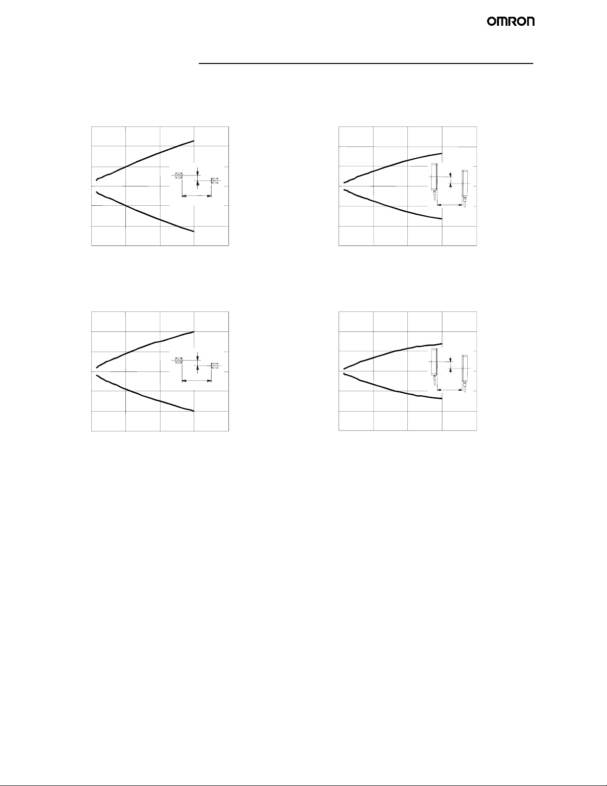
Engineering Data
J OPERATING RANGE
F3S-B122P
Perpendicular to Center Line of Lenses Parallel to Center Line of Lenses
300
300
200
100
0
--100
Distance Y (mm)
--200
--300
02468
X
Y
200
100
0
--100
Distance Y (mm)
--200
--300
02468
Distance X (m)Distance X (m)
X
F3S-B662P
Perpendicular to Center Line of Lenses Parallel to Center Line of Lenses
300
200
100
0
--100
Distance Y (mm)
--200
--300
02468
X
Y
300
200
100
0
--100
Distance Y (mm)
--200
--300
02468
Distance X (m)Distance X (m)
X
Y
Y
8
Page 8

Operation
J I/O CIRCUIT DIAGRAM
IR--light
Interlock
indicator
indicator
Grey
Pink
5
6
Main emitter
circuit
Ext. test/blanking
indicator
Brown
2
Green
3
External test
input
White
1
Relay monitoring
input
Yellow
4
Interlock selection
input
F3S-B
+24 V
Blue
7
ON--state
Pink
Grey
indicator
6
5
RS--485(A)
RS--485(B)
OFF--state
indicator
Main receiver
circuit
Instability
indicator
Brown
2
Green
3
Control output 1
White
1
Control output 2
Yellow
4
Instability
output
Blue
7
Load
Load
Load
0V
9
Page 9

F3S-B
Dimensions
Unit: mm
J F3S-B SAFETY LIGHT CURTAIN
M12
connector
Master Unit
3
9.5
A
B
Part number A(Protective height) B (Full length)
F3S-B122 300 343
F3S-B182 450 493
F3S-B242 600 643
F3S-B302 750 793
F3S-B362 900 943
F3S-B422 1050 1093
F3S-B482 1200 1243
F3S-B542 1350 1393
F3S-B602 1500 1543
F3S-B662 1650 1693
3
M12 connector
34
10.5
40.3
30
10
Page 10

J MOUNTING BRACKET (TOP AND BOTTOM)
5.5
.
12
16
22
20
20°
35°
46
30
R2.75
R1.75
∅ 25.5
3.5
F3S-B
2
36
R4.5
J MOUNTING PLATE
Only supplied with types which have a protective height of 1,050 mm or longer (including intermediate brackets). Only needed for rear
mounting.
6.25
42.74
36.5
20
4
5.5
3
22.5
R2.75
7
5
28.74
12
J INTERMEDIATE MOUNTING BRACKET
Mounting screw for
sensor (M6x8)
Flat intermediate
bracket
12.5
Note: An Intermediate Mounting
Bracket is only needed for
types which have a protective
height of 1,050 mm or more.
13
36
15.5
24
3.5
3.2
0.65
2
7
8
0.65
24
Rubber
24
16
12
11
5.5
15
40
16
3.2
L--shaped
intermediate bracket
31.3
14
U-shaped
intermediate
bracket
Fixing
screw for
bracket
(M4x10)
5.5
42
15
30
11
Page 11
F3S-B
Opti
(
OrderS
)
ons
Unit: mm
eparately
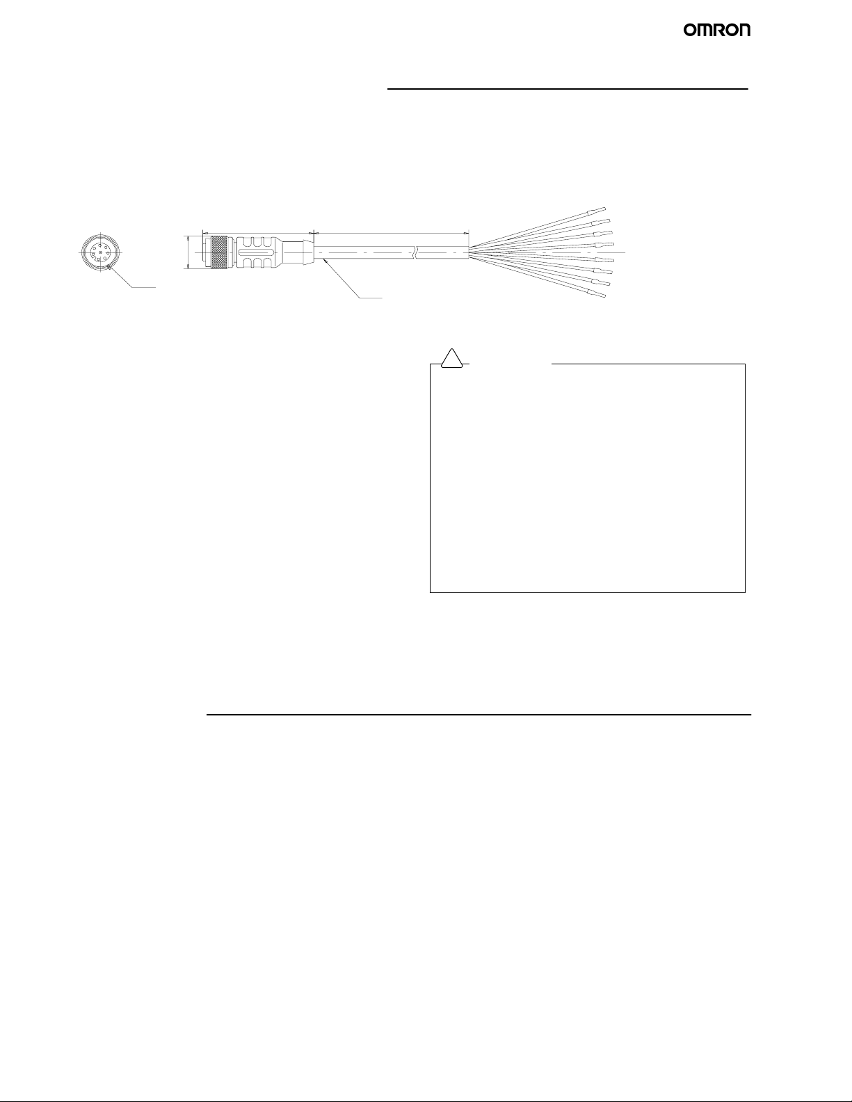
J EXTENSION CABLE (SET OF 2: EMITTER = GRAY, RECEIVER = BLACK)
F39-JB1A (L = 3 m)
F39-JB2A (L = 7 m)
F39-JB3A (L = 10m)
42 L
∅ 15
M12
Round vinyl-- insulated cord
5.7 mm dia. (32 @ 0.1 mm dia. each) 8 cores
J F39-EU1E OPTIONAL FUNCTION KIT
This set includes the following items:
D F39-U1E Optional Function Software
D F39-E1 Interface Unit
D F39-JB1C Interface Cable
The F39-U1E Optional Function Software is the WINDOWSR
based software for use with the F39-E1 Interface Unit to program
the F3S-B Safety Light Curtain. The software is provided on one
3.5 inch floppy disk. The software has the features listed below.
Set the following functions to the F3S-B:
1. Start interlock function
2. Relay monitoring function
3. Blanking function
D Display each axis and each input line condition of the F3S-B
D Change the ON delay time
Note: The F3S-B is not in normal operation during connection
with the F39-E1. The control outputs are held in their
OFF-state. For detailed information please refer to
Details of Optional Function Ki t, E39-EU1E in this data
sheet.
!
WARNING
After setting the blanking function, check that the F3S-B
detects a test rod at any position in the F3S-B detection zone
through which a person reaches the hazardous part of the
machine. If any positions are found by check above, install
protective structures to there to prevent intrusion which the
F3S-B can not detect. Failure to do so may result in serious
injury.
Perform the installation check and the periodical inspection
described in the F3S-B manual.
Disconnect the outputs of the F3S-B from the load when
programming it using the F39-U1E software and with F39-E1
Interface Unit. Failure to do so may result in serious injury.
Do not connect the F39-E1 to a power supply with a voltage
higher than 24 VDC +20 %. Do not connect the F39 -E1 to an
AC power supply.
Installation
J WIRING
Disconnect all sources of power before wiring the F3S-B to a machine.
D Connect the emitter extension cable (F39-JBjA--L optional, gray color outer jacket) to the emitter. (The emitter uses gray color
plastic caps.)
D Connect the receiver extension cable (F39-JBjA--D optional, black color outer jacket) to the receiver. (The receiver unit uses
black color plastic caps.)
D Connect the 0 V line of the power supply directly to protective earth (PE).
Note: Be sure to wire correctly. Failure to do so may damage the F3S-B.
12
Page 12

J CONNECTOR (MAIN UNIT END)
8
5
3
4
Front view Pin no. Signal name Wire color
of Extension Cable
1 Control output 2 Relay monitoring input White
7
6
1
865
2
4
3
2 24 VDC 24 VDC Brown
3 Control output 1 External test input Green
4 Instability output Interlock selection input Yellow
5 RS-485 (A) RS-485 (A) Grey
6 RS-485 (B) RS-485 (B) Pink
7 0V 0V Blue
8 N.C. / reserved N.C. / reserved Red
Note: N.C. / reserved: do not connect
Emitter
Receiver Emitter
Receiver
F3S-B
E1: 24 VDC Power supply
S1: External test switch
K1, K2: Relay or PLC input to control the dangerous
movement of a machine
RS--485(A) (Grey 5)
RS--485(B) (Pink 6)
24 VDC (Brown 2)
Relay monitoring (White 1)
Ext. test (Green 3)
S1
E1
0V(Blue7)
24 VDC (Brown 2)
Interlock selection (Yellow 4)
Instability (Yellow 4)
K3
K3: Relay to indicate unstable condition
Output2(White1)
Output 1 (Green 3)
0V(Blue7)
K1
K2
13
Page 13

F3S-B
L
A
When Using START/RESTART FUNCTION When Using Optional RE
Emitter
S2
0V(Blue7)
24 VDC (Brown 2)
E1
S2: Restart interlock reset switch
Interlock selection (Yellow 4)
RS--485(A) (Grey 5)
RS--485(B) (Pink 6)
Receiver
Instability (Yellow 4)
K3
k1
0V(Blue7)
24 VDC (Brown 2)
k2
Relay monitoring (White 1)
k1, k2: Auxiliary contact to monitor the condition of the final relay
Emitter
Ext. test (Green 3)
S1
E1
J DETAILS OF F39-EU1E OPTIONAL FUNCTION KIT
Preparation
!
Caution
Perform the installation check and the periodical inspection described in the F3S-B manual.
Do not disassemble, repair or modify the F39-E1.
Do not use the F39-E1 in flammable or explosive environments.
Y MONITORING FUNCTION
0V(Blue7)
24 VDC (Brown 2)
To use the F39-U1E software, the following items are necessary.
• Personal Computer (not included)
-- Windows 95, Windows 98, or Windows NT
-- 133MHz Pentium processor or better
-- 32MB RAM or higher for Windows 95 and Windows 98
-- 64MB RAM or higher for Windows NT
-- A 115kBd RS-232 serial interface port or better
• F39-E1 Interface Unit
35
60
8
114
• F39-JB1C Interface Cable 5 m cabl e length,
M8 connector (4 pins)
30.5 5000
∅ 15
Round vinyl--insulated cord
5 mm dia. (32/0.1 mm dia.) 4 cores
• RS-232C Cable (not incl uded)
14
Page 14

J COMPONENT NAMES AND FUNCTIONS OF THE F39-E1 INTERFACE UNIT
SEND to HS-485 indicator (Red)
SEND to HS-232C indicator (Yellow)
M8 Connector (RS-485)
Communication indicator (Green)
9pin D-Sub Connector
(HS-232C)
SEND to RS-485 Indicator (Red) Lit when the F39-E1 sends data to the F3S -B via RS-485.
SEND to RS-232C Indicator (Yellow) Lit when the F39-E1 sends data to the PC via RS-232C.
COMMUNICATION Indicator (Green) Flashing during communication between the F 3S-B and the F39 -E1.
J HARDWARE CONNECTION
!
WARNING
Disconnect the outputs of the F3S-B from the load when programming it using the F39-U1E software and with F39-E1 Interface
Unit. Failure to do so may result in serious injury.
Do not connect the F39-E1 to a power supply with a voltage higher than 24 VDC +20 %.
Do not connect the F39-E1 to an AC power supply.
F3S-B
Wiring Diagram
PC
RS-232C
F39- - E 1
F39
-JB1C
F39--U1E
See
Note.
+24V(Brown 1)
0V(Blue 3)
RS-485 (A) (Black 4)
RS-485 (B) (White 2)
Emitter
0V (Blue 7)
24 VDC (Brown 2)
F3S- B
RS-485 (A)
(Grey 5)
RS-485 (B)
(Pink 6)
No. 1 ax is
Receiver
24 VDC (Brown 2)
Wiring Procedure
1. For wiring connections, use the F3S-B
Instruction Manual (enclosed with the product).
2. Connect the Interface Cable (F39-JB1C) to the
Interface Unit (F39-E1).
3. Connect the 4 wires of the Interface Cable to
each appropriate line of the F3S-B.
4. Connect an RS-232C Cable to the PC and to the
Interface Unit.
See
Note.
0V (Blue 7)
Open Output 1 (Green 3)
Open Output 2 (White 1)
15
Page 15

F3S-B
J SOFTWARE INSTALLATION
Copy the file ”F39-U1E_ver#.#.exe” and F39-U1E_ver#.#dat from
the 3.5--inch floppy disk (enclosed with the product) onto the hard
disk of the PC.
J FUNCTION DESCRIPTION
Start Interlock
When the Start interlock function is used, the F3S -B does not go
to the ON-state automatically after power ON. Interrupting one or
more axes resets the start interlock condition of the F3S--B then
starts normal operation. The duration of the interruption must be
equal or shorter as defined in the »Max. interruption time (sec)« .
Max. Interruption Time
The max interruption time can be set between 0.3and2s.
Note: In the case both the Start interlock and the Start/restart
interlock are selected, only the Start/restart interlock will
be activate.
Start/Restart interlock is a function which is selected by w iring.
Refer to the instruction manual of the F3S-B for more detailed
information.
Relay Monitoring
MPCEs (Machine Primary Control Elements) are usually relays
or contactors used to control hazardous movement directly. The
state of the MPCEs can be checked with the Relay monitoring
function.
A voltage of 17 VDC to Vs (Supplied voltage to F3S-B) has to be
applied to the Relay monitoring input through the NC contacts of
the MPCEs when the F3S -B control outputs are in the OFF--state
(see the F3S-B manual for wiring information). To ensure this
logic relation, the MPCEs must be safety approved types, with
forcibly guided contacts.
Allowed Relay Delay Time
The allowed relay delay time can be set between 20 and 300
ms. This delay time has to be set at least 20 milliseconds shorter
than the Outputs ON delay time.
Outputs ON Delay
You can set the ON delay time of control outputs between 80 and
400 ms. This corresponds to the time which the control outputs
go to ON-state after the detection zone is not interrupted.
Note: 1. When the Relay monitoring function is also used, the
ON delay time must meet the formula below.
2. ON delay time ≥ Allowed relay delay time + 20 ms
After the Relay monitoring function is set, if the ON
delay time does not meet the above formula, the
ON delay time will be changed automatically into
Allowed relay delay time +20ms.
Blanking
With the Blanking function, one or more axes can be disabled.
This function is useful in an application where a part of the F3S-B
detection zone is alw ays interrupted. The Manual setting and the
Teaching setting are available to select the blanked axes.
Note: 1. In the case the blanked zone is not filled with structure
completely and remains some opening, the opening
must be filled with the protective structure.
2. All axes can not be disabled. At least one axis needs to
be active.
J RATINGS AND PERFORMANCE
Type
Supply voltage 24 VDC ± 20% (including 5 Vp-- p ripple)
Current consumption 120 mA max.
Interface RS-232C interface, RS --485 interface
Connection method RS-485: 4pins, M 8 connector, RS--232C: D-- SUB connector, 9 pins
Protection circuit RS 485 protection against wrong wiring
Ambient temperature During operation: -10 to 55° C (with no freezing), During storage: -25 to 70° C
Ambient humidity During operation : 35 to 85% RH (with no condensation)
Ambient humidity During storage: 35 to 95% RH
Insulation resistance 20 MΩ min. (at 500 VDC)
Dielectric strength voltage 500 VAC, 50/60 Hz, for 1 min.
Degree of protection IEC60529, IP20
Shock resistance Normal operation: 150 m/s2[15 G], ±X, ±Y and ±Z directions: 3 times
Vibration resistance Normal operation: 10 to 55 Hz, double-- amplitude: 0.3 mm, X, Y and Z directions: 10 sweeps
Cable length RS-485 cable: 5 m (4 pin 0.25 mm2), RS--232C cable: Standard
Materials Case: Aluminum
Size 122 x 60 x 35 mm
Conformity EMC Directive
F39-E1 Interface Unit
16
Page 16
Precautions
!
WARNING
1. D o not use the F3S-B on machines that can not be stopped by electrical control in case of an emergency.
2. D o not use the F3S-B in flammable or explosive environments.
3. Al ways maintain the safety distance between F3S-B and a hazardous part of the machine. Serious injury may result if the
machine does not stop before someone reaches the hazardous part.
4. Install protective structures around a machine so that you must pass through the detection zone to reach a hazardous part of
the machine.
5. Install F3S-B so that some parts of the operator’s body remain in the detection zone at all times when the operator works in that
hazardous area.
6. Fai lure to do so may result in serious injury.
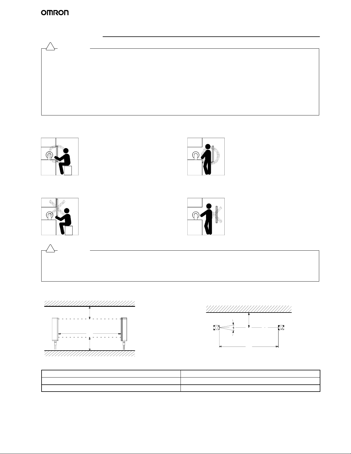
J CORRECT INSTALLATION
A hazardous part of a machine can be
reached only by passing through the sensor
detection zone.
Some part of the operator’s body remains in
the detection zone while they are working.
F3S-B
J INCORRECT INSTALLATION
A hazardous part of the machine can be
reached without passing through the sensor
detected zone.
!
WARNING
1. Be sure to install the F3S-B to minimize the effects of reflections from reflective surfaces.
Failure to do so will create an inability to detect and may result in serious injury.
2. Install the F3S-B with a minimum distance D as shown below from the reflective surface (highly reflective surfaces)
like metal walls, floors, ceilings, and work pieces.
Side View
Reflecting ceiling
Emitter Receiver
D
Detection zone
L
D
Top View
Emitter Receiver
A worker isbetween thesensor detectionzone
and a hazardous part of a machine.
Reflecting surface
D
5°
5°
L
Reflecting floor
Distance between emitter and receiver (detection distance L) Minimum installation (distance D)
0.3to3m 0.27 m
3to5m Lxtan5° = L x 0.087 (m)
17
Page 17
F3S-B
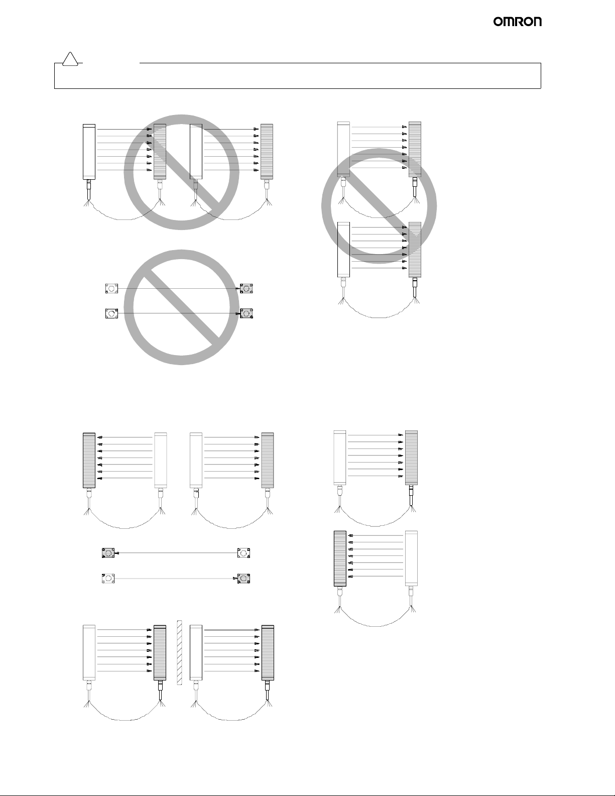
!
WARNING
When using multiple sets of the F3S-B, install them so that mutual interference is not incurred.
Incorrect
Emitter 1
RS--485
Receiver 1
Emitter 2
RS--485
Receiver 2
Incorrect
Emitter 1
Emitter 2
Receiver 1
Receiver 2
J ALTERNATE EMITTERS AND RECEIVERS
Correct installations are shown below to prevent mutual interference.
Incorrect
Emitter 1
Emitter 2
RS--485
Receiver 1
Receiver 2
Receiver 1
Receiver 1
Emitt er 2
Emitter 1
Correct
Emitter 1
RS--485 RS--4 85
Emitter 2
Correct
Correct
Receiver 1
RS--485 RS--485
Emitter 2
Receiver 2
Emitter 1
Receiver 2
Receiver 2
Emitter 1
Receiver 2
Correct
Receiver 1
RS--485
Emitter 2
RS--485
18
Page 18
!
WARNING
1. The F3S-B is a TYPE 2 electro-sensitive protective equipment, intended to be used as or with the safety related part
of control system to category 2,1, or B as defined in the
European standard EN954-1.
Do not use the F3S-B in category 3 or 4 systems.
2. A qualified person, as determined by local regulations,
must confirm that installation, inspection and maintenance
are implemented correctly.
3. Do not short the output lines to the +24 V line. Doing so will
cause the output to be always ON, creating a hazardous
situation.
4. D o not connect the F3S-B to a power supply with voltage
higher than 24 VDC + 20%. Do not connect the F3S-B to
OMRON ELECTRONICS LLC
an AC power supply.
One Commerce Drive
5. Be sure to conduct inspections regularly.
Schaumburg, IL 60173
6. The F3S-B cannot be used in applications where hazardous projectiles may exit the protected zone.
847-843-7900
7. D o not disassemble, repair, or modify the F3S -B.
For US technical support or other inquiries:
8. D C power supply units must satisfy all of the conditions
800-556-6766
below so that the F3S-B can comply with the applicable
standards IEC 61496-1 and UL 508.
(1.) The power supply voltage must be within rating
(24 VDC ± 20 %).
(2.) The power supply is connected only to the F3S-B and
to the electro-sensitive protective function of the
F3S-B, such as a safety controller and muting
sensors, and it has enough rated current for all the
devices.
(3.) The power supply uses double or reinforced i nsulation
between the primary and secondary circuits.
(4.) The power supply automatically resets overcurrent
protection characteristics (voltage drop).
2/03 Specifications subject to change without notice
F3S-B
(5.) The power supply maintains an output holding time
of at least 20 ms.
(6.) FG (frame ground terminal) must be connected to
PE (protective earth) when using a commercially
available switching regulator.
(7.) The power supply must have output characteristics
required for the power source for Class 2 Circuit or
Limited Voltage/Current Circuit as defined in UL508.
(8.) The power supply must conform to regulatory
requirements and standards, regarding EMC and
electrical equipment safety, of the country where the
F3S-B is installed and where machinery will be
operated. For example: The EMC Directive
(industrial environment) and the Low Voltage
Directive in EU.
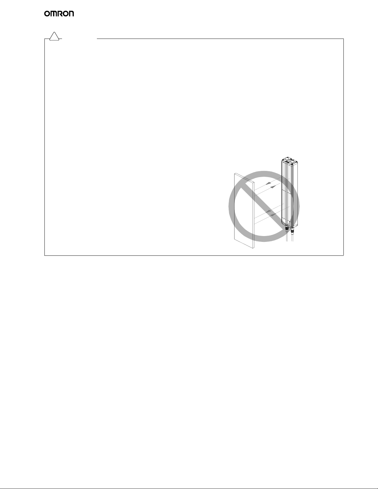
9. D o not use the F3S-B in a retroreflective configuration, or
detection may fail.
19
Page 19

Terms and Conditions of Sale
1. Offer; Acceptance. These terms and conditions (these "Terms") are deemed
part of all quotes, agreements, purchase orders, acknowledgments, price lists,
catalogs, manuals, brochures and other documents, whether electronic or in
writing, relating to the sale of products or services (collectively, the "Products
by Omron Electronics LLC and its subsidiary companies (“Omron”). Omron
objects to any terms or conditions proposed in Buyer’s purchase order or other
documents which are inconsistent with, or in addition to, these Terms.
2. Prices; Payment Terms.
out notice by Omron. Omron reserves the right to increase or decrease prices
on any unshipped portions of outstanding orders. Payments for Products are
due net 30 days unless otherwise stated in the invoice.
3. Discounts.
sent to Buyer after deducting transportation charges, taxes and duties, and will
be allowed only if (i) the invoice is paid according to Omron’s payment terms
and (ii) Buyer has no past due amounts.
4. Interest.
the maximum legal rate, whichever is less, on any balance not paid within the
stated terms.
5. Orders
6. Governmental Approvals.
costs involved in, obtaining any government approvals required for the importation or sale of the Products.
7. Taxes
real property and income taxes), including any interest or penalties thereon,
imposed directly or indirectly on Omron or required to be collected directly or
indirectly by Omron for the manufacture, production, sale, delivery, importation, consumption or use of the Products sold hereunder (including customs
duties and sales, excise, use, turnover and license taxes) shall be charged to
and remitted by Buyer to Omron.
8. Financial.
to Omron, Omron reserves the right to stop shipments or require satisfactory
security or payment in advance. If Buyer fails to make payment or otherwise
comply with these Terms or any related agreement, Omron may (without liability and in addition to other remedies) cancel any unshipped portion of Products sold hereunder and stop any Products in transit until Buyer pays all
amounts, including amounts payable hereunder, whether or not then due,
which are owing to it by Buyer. Buyer shall in any event remain liable for all
unpaid accounts.
9. Cancellation; Etc.
unless Buyer indemnifies Omron against all related costs or expenses.
10. Force Majeure
resulting from causes beyond its control, including earthquakes, fires, floods,
strikes or other labor disputes, shortage of labor or materials, accidents to
machinery, acts of sabotage, riots, delay in or lack of transportation or the
requirements of any government authority.
11. Shipping; Delivery.
a.Shipments shall be by a carrier selected by Omron; Omron will not drop ship
b.Such carrier shall act as the agent of Buyer and delivery to such carrier shall
c. All sales and shipments of Products shall be FOB shipping point (unless oth-
d.Delivery and shipping dates are estimates only; and
e.Omron will package Products as it deems proper for protection against nor-
12. Claims.
Products occurring before delivery to the carrier must be presented in writing
to Omron within 30 days of receipt of shipment and include the original transportation bill signed by the carrier noting that the carrier received the Products
from Omron in the condition claimed.
13. Warranties
Products will be free from defects in materials and workmanship for a period of
twelve months from the date of sale by Omron (or such other period expressed
in writing by Omron). Omron disclaims all other warranties, express or implied.
(b) Limitations
EXPRESS OR IMPLIED, ABOUT NON-INFRINGEMENT, MERCHANTABIL-
Cash discounts, if any, will apply only on the net amount of invoices
Omron, at its option, may charge Buyer 1-1/2% interest per month or
. Omron will accept no order less than $200 net billing.
. All taxes, duties and other governmental charges (other than general
If the financial position of Buyer at any time becomes unsatisfactory
except in “break down” situations.
constitute delivery to Buyer;
erwise stated in writing by Omron), at which point title and risk of loss shall
pass from Omron to Buyer; provided that Omron shall retain a security interest in the Products until the full purchase price is paid;
mal handling and extra charges apply to special conditions.
Any claim by Buyer against Omron for shortage or damage to the
. (a) Exclusive Warranty. Omron’s exclusive warranty is that the
All prices stated are current, subject to change with-
Buyer shall be responsible for, and shall bear all
Orders are not subject to rescheduling or cancellation
. Omron shall not be liable for any delay or failure in delivery
Unless otherwise expressly agreed in writing by Omron:
. OMRON MAKES NO WARRANTY OR REPRESENTATION,
ITY OR FITNESS FOR A PARTICULAR PURPOSE OF THE PRODUCTS.
BUYER ACKNOWLEDGES THAT IT ALONE HAS DETERMINED THAT THE
PRODUCTS WILL SUITABLY MEET THE REQUIREMENTS OF THEIR
")
INTENDED USE. Omron further disclaims all warranties and responsibility of
any type for claims or expenses based on infringement by the Products or otherwise of any intellectual property right. (c) Buyer Remedy
gation hereunder shall be, at Omron’s election, to (i) replace (in the form
originally shipped with Buyer responsible for labor charges for removal or
replacement thereof) the non-complying Product, (ii) repair the non-complying
Product, or (iii) repay or credit Buyer an amount equal to the purchase price of
the non-complying Product; provided that in no event shall Omron be responsible for warranty, repair, indemnity or any other claims or expenses regarding
the Products unless Omron’s analysis confirms that the Products were properly handled, stored, installed and maintained and not subject to contamination, abuse, misuse or inappropriate modification. Return of any Products by
Buyer must be approved in writing by Omron before shipment. Omron Companies shall not be liable for the suitability or unsuitability or the results from the
use of Products in combination with any electrical or electronic components,
circuits, system assemblies or any other materials or substances or environments. Any advice, recommendations or information given orally or in writing,
are not to be construed as an amendment or addition to the above warranty.
See http://oeweb.omron.com or contact your Omron representative for published information.
14. Limitation on Liability; Etc
FOR SPECIAL, INDIRECT, INCIDENTAL, OR CONSEQUENTIAL DAMAGES,
LOSS OF PROFITS OR PRODUCTION OR COMMERCIAL LOSS IN ANY
WAY CONNECTED WITH THE PRODUCTS, WHETHER SUCH CLAIM IS
BASED IN CONTRACT, WARRANTY, NEGLIGENCE OR STRICT LIABILITY.
Further, in no event shall liability of Omron Companies exceed the individual
price of the Product on which liability is asserted.
15. Indemnities
their employees from and against all liabilities, losses, claims, costs and
expenses (including attorney's fees and expenses) related to any claim, investigation, litigation or proceeding (whether or not Omron is a party) which arises
or is alleged to arise from Buyer's acts or omissions under these Terms or in
any way with respect to the Products. Without limiting the foregoing, Buyer (at
its own expense) shall indemnify and hold harmless Omron and defend or settle any action brought against such Companies to the extent based on a claim
that any Product made to Buyer specifications infringed intellectual property
rights of another party.
16. Property; Confidentiality.
sive property of Omron Companies and Buyer shall not attempt to duplicate it
in any way without the written permission of Omron. Notwithstanding any
charges to Buyer for engineering or tooling, all engineering and tooling shall
remain the exclusive property of Omron. All information and materials supplied
by Omron to Buyer relating to the Products are confidential and proprietary,
and Buyer shall limit distribution thereof to its trusted employees and strictly
prevent disclosure to any third party.
17. Export Controls.
licenses regarding (i) export of products or information; (iii) sale of products to
“forbidden” or other proscribed persons; and (ii) disclosure to non-citizens of
regulated technology or information.
18. Miscellaneous
and no course of dealing between Buyer and Omron shall operate as a waiver
of rights by Omron. (b) Assignment
without Omron's written consent. (c) Law.
law of the jurisdiction of the home office of the Omron company from which
Buyer is purchasing the Products (without regard to conflict of law principles). (d) Amendment
Buyer and Omron relating to the Products, and no provision may be changed
or waived unless in writing signed by the parties. (e) Severability
sion hereof is rendered ineffective or invalid, such provision shall not invalidate
any other provision. (f) Setoff
against the amount owing in respect of this invoice. (g) Definitions
herein, “including
nies” (or similar words) mean Omron Corporation and any direct or indirect
subsidiary or affiliate thereof.
. Buyer shall indemnify and hold harmless Omron Companies and
Buyer shall comply with all applicable laws, regulations and
. (a) Waiver. No failure or delay by Omron in exercising any right
. OMRON COMPANIES SHALL NOT BE LIABLE
Any intellectual property in the Products is the exclu-
. Buyer may not assign its rights hereunder
These Terms are governed by the
. These Terms constitute the entire agreement between
. Buyer shall have no right to set off any amounts
” means “including without limitation”; and “Omron Compa-
. Omron’s sole obli-
. If any provi-
. As used
Certain Precautions on Specifications and Use
1. Suitability of Use. Omron Companies shall not be responsible for conformity
with any standards, codes or regulations which apply to the combination of the
Product in the Buyer’s application or use of the Product. At Buyer’s request,
Omron will provide applicable third party certification documents identifying
ratings and limitations of use which apply to the Product. This information by
itself is not sufficient for a complete determination of the suitability of the Product in combination with the end product, machine, system, or other application
or use. Buyer shall be solely responsible for determining appropriateness of
the particular Product with respect to Buyer’s application, product or system.
Buyer shall take application responsibility in all cases but the following is a
non-exhaustive list of applications for which particular attention must be given:
(i) Outdoor use, uses involving potential chemical contamination or electrical
interference, or conditions or uses not described in this document.
(ii) Use in consumer products or any use in significant quantities.
(iii) Energy control systems, combustion systems, railroad systems, aviation
systems, medical equipment, amusement machines, vehicles, safety equipment, and installations subject to separate industry or government regulations.
(iv) Systems, machines and equipment that could present a risk to life or property. Please know and observe all prohibitions of use applicable to this Product.
NEVER USE THE PRODUCT FOR AN APPLICATION INVOLVING SERIOUS
RISK TO LIFE OR PROPERTY OR IN LARGE QUANTITIES WITHOUT
ENSURING THAT THE SYSTEM AS A WHOLE HAS BEEN DESIGNED TO
ADDRESS THE RISKS, AND THAT THE OMRON’S PRODUCT IS PROPERLY RATED AND INSTALLED FOR THE INTENDED USE WITHIN THE
OVERALL EQUIPMENT OR SYSTEM.
2. Programmable Products.
user’s programming of a programmable Product, or any consequence thereof.
3. Performance Data
and other materials is provided as a guide for the user in determining suitability and does not constitute a warranty. It may represent the result of Omron’s
test conditions, and the user must correlate it to actual application requirements. Actual performance is subject to the Omron’s Warranty and Limitations
of Liability.
4. Change in Specifications
changed at any time based on improvements and other reasons. It is our practice to change part numbers when published ratings or features are changed,
or when significant construction changes are made. However, some specifications of the Product may be changed without any notice. When in doubt, special part numbers may be assigned to fix or establish key specifications for
your application. Please consult with your Omron’s representative at any time
to confirm actual specifications of purchased Product.
5. Errors and Omissions.
checked and is believed to be accurate; however, no responsibility is assumed
for clerical, typographical or proofreading errors or omissions.
Omron Companies shall not be responsible for the
. Data presented in Omron Company websites, catalogs
. Product specifications and accessories may be
Information presented by Omron Companies has been
Page 20

&RPSOHWH¦7HUPVDQG&RQGLWLRQVRI6DOH§IRUSURGXFWSXUFKDVHDQGXVHDUHRQ2PURQ©VZHEVLWH
DWZZZRPURQFRPRHL¤XQGHUWKH¦$ERXW8V§WDELQWKH/HJDO0DWWHUVVHFWLRQ
$//',0(16,2166+2:1$5(,10,//,0(7(56
7RFRQYHUWPLOOLPHWHUVLQWRLQFKHVPXOWLSO\E\7RFRQYHUWJUDPVLQWRRXQFHVPXOWLSO\E\
20521(/(&7521,&6//&
2QH&RPPHUFH'ULYH
6FKDXPEXUJ,/
)RU86WHFKQLFDOVXSSRUWRURWKHULQTXLULHV
20521&$1$'$,1&
0LOQHU$YHQXH
7RURQWR2QWDULR0%9
2052121/,1(
*OREDOKWWSZZZRPURQFRP
86$KWWSZZZRPURQFRPRHL
&DQDGDKWWSZZZRPURQFD
Cat. No. GC SAFETY-3 07/05 Specifications subject to change without notice Printed in USA
 Loading...