


Cat. No. E502-E2-01
F3S-B Series
Safety Light Curtain
Instruction Manual


F3S-B
Introduction
Thank you for purchasing the F3S-B series Safety Light Curtain.
Always heed the following points when using the F3S-B:
• Make sure that personnel operating the F3S-B are knowledgeable about the machine on which it is
installed
• Read this manual completely and be sure you understand the information provided before attempting
to operate the F3S-B
• Keep the manual in a secure and convenient location and refer to it as necessary.
Regulations and Standards
(1) The F3S-B has not received the type approval provided by Article 44-2 of the Industrial Safety and
Health Law of Japan. Therefore, it cannot be used in Japan as a safety device for pressing or shearing
machines provided by article 42 of that law.
(2) The F3S-B is electro-sensitive protective equipment (ESPE) in accordance with European Union (EU)
Machinery Directive Annex IV, B. Safety Components, Item 1.
The F3S-B complies with the following regulations and standards.
• EU regulations and technical standards:
– Machinery Directive: No. 98/37/EC
– EMC Directive: No. 89/336/EEC
– EN 61496-1 (06/98) (Type 2 ESPE), IEC 61496-2 (1997) (Type 2 AOPD)
• IEC standards
– IEC 61496-1 (1997) (Type 2 ESPE), IEC 61496-2 (1997) (Type 2 AOPD)
(3) The F3S-B received the following approvals from the EU accredited bodies.
- Certificate of a Notified Body for EC Type-Examination referred to in the EU Machinery Directive
Annex IV, from TÜV Hannover/Sachsen-Anhalt e.V.
- Certificate of a Competent Body referred to in the EU EMC Directive, from Technischer Überwachungs-Verein Nord
(4) The F3S–B received the following approvals from the third–party testing laboratory UL.
– UL Listed (UL508, IEC61496-1 and –2)
– UL Listed to Canadian safety standards (CSA C22.2 No. 14 and No.0.8, IEC61496-1 and –2)
– Programmable system certificate (UL1998, IEC61496–1)
(5) The following standards are referenced when designing the F3S–B. To comply with these standards,
be sure to design and use in accordance with all regulations and standards related to them.
Contact an expert agency such as TÜV and UL if any of the above points are unclear.
– EN415–4
– OSHA 29 CFR 1910. 212
– ANSI/RIA 15.06 (Risk reduction category : R2B)
Precaution on Safety
! General conventions for safe use
The following conventions are used for precautionary items in this manual in order to ensure safe and
proper use of the F3S-B. Items listed here are critical for safety and must be heeded at all times.
WARNING
!
!
!!
Indicates a potentially hazardous situation which, if not
avoided, could result in death or serious injury.
Indicates prohibited actions.
3
F3S-B
WARNING
The F3S-B is a TYPE 2 Electro-sensitive protective equipment, intended to be used as or with the safety
related part of control system to category 2,1, or B as defined in the European standard EN954-1.
Do not use the F3S-B in category 3 or 4 systems.
Do not use the F3S-B on machines that cannot be stopped by electrical control in case of an emergency.
Install protective structures around the machine so that you must pass through the detection zone to
reach a hazardous part of the machine (see “2-1 Installation Conditions”).
Install the F3S-B so that some part of the operator’s body remains in the detection zone at all times
when the operator works in a hazardous area (see “2-1 Installation Conditions”).
Failure to do so may result in serious injury.
A qualified person, as determined by local regulations, must confirm that installation, inspection and
maintenance are implemented correctly.
Always maintain the safety distance between the F3S-B and a hazardous part of a machines (see “2-1
Installation Conditions”).
Do not install the F3S-B in a location affected by wall reflections (see “2-1 Installation Conditions”).
Do not short the output lines to the +24 V line. Doing so will cause the output to be always ON, creating
a hazardous situation.
Do not connect the F3S-B to a power supply with voltage higher than 24 VDC + 20 %.
Do not connect the F3S-B to an AC power supply.
Be sure to conduct inspections regularly (see “6 Maintenance”).
The F3S-B cannot be used in applications where hazardous projectiles may exit the protected zone.
Do not disassemble, repair or modify the F3S-B.
Do not use the F3S-B in flammable or explosive environments.
DC power supply units must satisfy all of the conditions below so that the F3S-B can comply with the
applicable standards IEC 61496-1 and UL 508.
• The power supply voltage must be within rating (24 VDC ± 20 %).
• The power supply is connected only to the F3S-B and to the devices related to the electro-sensitive
protective function of the F3S-B, such as a safety controller and muting sensors, and it has enough
rated current for all the devices. The power supply is not connected to other devices or machines.
• The power supply uses double or reinforced insulation between the primary and secondary circuits
• The power supply has automatic reset characteristics (voltage drop) to protect overcurrent.
• The power supply maintains an output holding time of at least 20 ms.
• FG (frame ground terminal) must be connected to PE (protective earth) when using a commercially
available switching regulator.
• The power supply must have output characteristics required for the power source for Class 2 Circuit
or Limited Voltage/Current Circuit as defined in UL508 (see “2-3-1 Remark”).
• The power supply must conform to regulatory requirements and standards, regarding EMC and elec-
trical equipment safety, of the country where the F3S-B is installed and where machinery will be operated, for example: The EMC Directive (industrial environment) and the Low Voltage Directive in
EU.
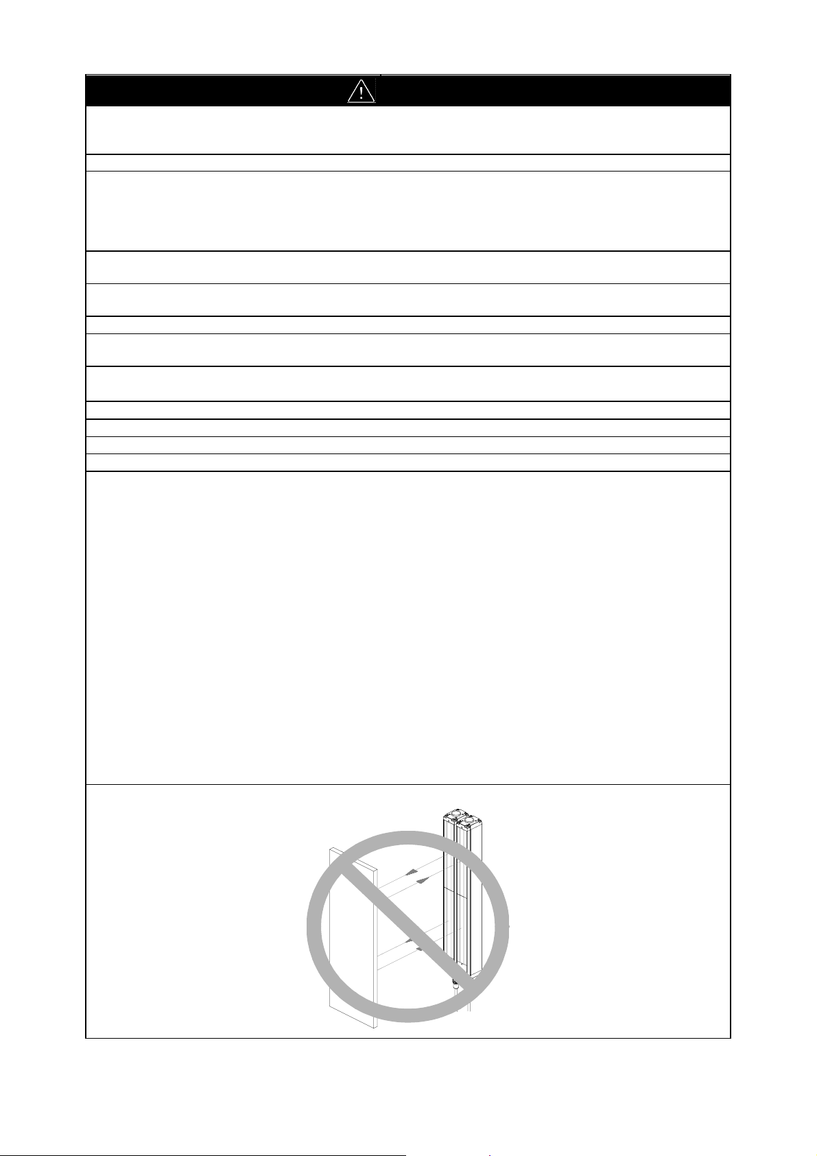
Do not use the F3S-B in a retroreflective configuration. Otherwise detection may fail.
4
F3S-B
Notice
For your safety, always pay attention to the following:
# Installation Environment
• Do not install the F3S-B in the following environments:
− Areas exposed to intense interference light such as direct sunlight.
− Areas with high-humidity where condensation is likely to occur.
− Areas exposed to corrosive gases.
− Areas exposed to vibration or shock levels higher than specification provisions.
− Areas where the light curtain may come in direct contact with water.
• Do not use radio equipment, such as cellular phones, walkie-talkies, or transceivers with high power,
near the F3S-B.
# Wiring and Mounting
• Be sure to route the F3S-B cable separate from high-potential power lines or through an exclusive
conduit.
• Be sure to turn OFF the power prior to wiring. Otherwise, the diagnostic function may prevent the
sensor from operating.
• When using cables with a connector other than the F39-JB series cable, make sure the connector is
rated IP54 or higher.
• The F3S-B will start operating in two seconds after the power is turned ON. Make sure that no op-
eration faults will occur in the control system during this time.
• The emitter and receiver are to be mounted in parallel and facing one another.
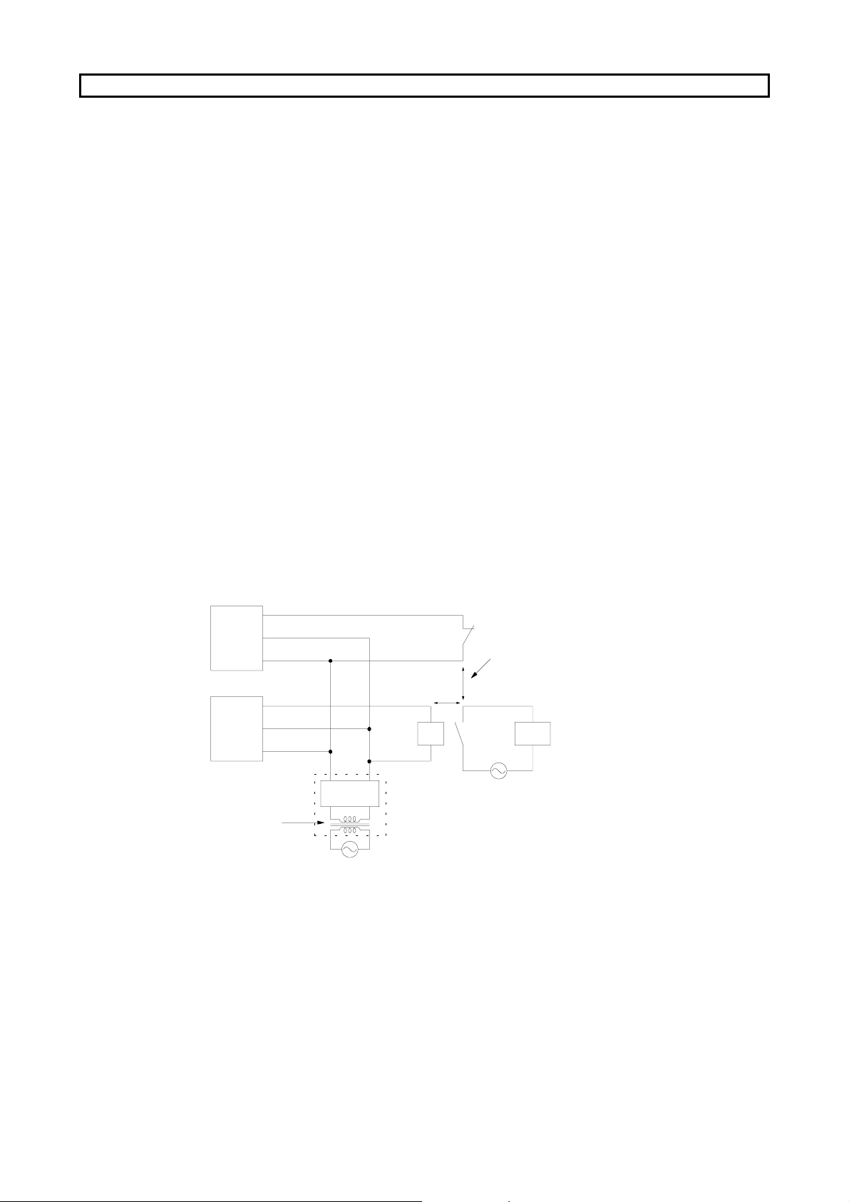
# Loads must satisfy all the conditions below.
• Is not short-circuited.
• Is not used with current higher than the rating.
• Is reinforced insulated or double insulated as shown in the following figure to prevent the output
from being subjected to a hazardous voltage when the load is a relay. The insulation shown in the
figure below should insulate against hazardous voltage levels (230 VAC, etc.), not simply against 24
VDC.
Relay monitoring input
Emitter
Receiver
Reinforced
insulation or
double
insulation
0 V
+24 V
Output
0 V
+24 V
Power
supply unit
k1
K1
Hazardous
voltage level
Reinforced insulation or double
insulation between the coil and
contacts, between contacts
k1
Hazardous
voltage level
Motor, etc.
# Two control outputs must be used.
# The procedures of installation and inspection in this manual should be read carefully.
# Do not use any solvents such as paint thinners, benzene or acetone to clean the F3S-B because they
will dissolve resin and paint.
# Do not use screw-locking adhesives (screw lock) to secure the cap unit or connector cap screws be-
cause the adhesive may cause the resin to deteriorate and crack.
# The F3S-B can not detect transparent or semi-transparent materials.
# After unpacking the emitter and receiver, install them facing each other.
# Be sure to dispose of the F3S-B as industrial waste.
5
F3S-B
PRIOR TO USE
Make sure the following items were supplied with each F3S-B, contact your nearest OMRON
representative or distributor if any item is missing.
• F3S-B unit (emitter qty. 1, receiver qty. 1)
• Mounting brackets (top and bottom) qty. 4
Sixteen M3 x 10 tapping screws
Sixteen M3 washers
Four L-shaped brackets
• Mounting brackets (intermediate) qty. 2
(Supplied with types which have a protective height of 1050 mm or longer)
Two M4×10 screws
Two L-shaped intermediate brackets
Two U-shaped intermediate brackets
Two M6×8 screws
• Mounting plates qty. 4
(Supplied with types which have a protective height of 1050 mm or longer)
• Test Rod Ø 30 mm qty. 1
(Supplied with F3S-B2P and BM2P)
• Instruction manual (this manual) qty. 1
(Supplied with F3S-BP and BMP)
6

F3S-B
TABLE OF CONTENTS
DESCRIPTION ................................................................................................................Section 1 ............................ 8
1-1 Basics .................................................................................................................................................. 8
1-2 Features............................................................................................................................................... 8
1-3 Standard Functions.............................................................................................................................. 8
1-3-1 Start/restart interlock................................................................................................................ 8
1-3-2 Testing ..................................................................................................................................... 8
1-3-3 Instability Output ...................................................................................................................... 9
1-4 Optional Functions ............................................................................................................................... 9
1-4-1 Start Interlock........................................................................................................................... 9
1-4-2 Relay Monitoring ...................................................................................................................... 9
1-4-3 Blanking ................................................................................................................................... 9
1-5 Detection zone ................................................................................................................................... 10
1-6 Configuration variation ....................................................................................................................... 10
1-6-1 Stand-alone type.................................................................................................................... 10
1-6-2 Series connection types......................................................................................................... 11
1-7 Ratings and Performance .................................................................................................................. 12
1-8 Indicators ........................................................................................................................................... 13
1-9 Table of Types ................................................................................................................................... 14
1-10 Table of Response Time.................................................................................................................. 15
1-10-1 Stand-alone type................................................................................................................... 15
1-10-2 Series connection types........................................................................................................ 15
WIRING and MOUNTING ............................................................................................Section 2.......................... 16
2-1 Installation Conditions........................................................................................................................ 16
2-1-1 Detection Zone and Intrusion Path ........................................................................................ 16
2-1-2 Safety Distance...................................................................................................................... 16
2-1-3 Distance from Reflective Surfaces......................................................................................... 19
2-1-4 How to Prevent Mutual Interference ...................................................................................... 19
2-2 Dimensional Drawings ....................................................................................................................... 21
2-2-1 F3S-B..................................................................................................................................... 21
2-2-2 Mounting Bracket (Top and Bottom)...................................................................................... 25
2-2-3 Mounting Plate ....................................................................................................................... 25
2-2-4 Mounting Bracket (Intermediate) ........................................................................................... 26
2-3 Wiring................................................................................................................................................. 27
2-3-1 Power Supply Units and Loads.............................................................................................. 27
2-3-2 Wiring Diagram ...................................................................................................................... 28
2-3-3 Wiring Procedure ................................................................................................................... 29
ADJUSTMENT ................................................................................................................Section 3..........................30
3-1 Adjustment Procedure ....................................................................................................................... 30
3-2 Check List .......................................................................................................................................... 30
I/O CIRCUIT....................................................................................................................Section 4 .......................... 32
APPLICATIONS.............................................................................................................. Section 5.......................... 33
5-1 Application (1) .................................................................................................................................... 33
5-2 Application (2) .................................................................................................................................... 33
MAINTENANCE .............................................................................................................Section 6 .......................... 34
6-1 Daily Inspections................................................................................................................................ 34
6-2 Inspection Every Six Month ............................................................................................................... 34
6-3 Cleaning............................................................................................................................................. 34
ACCESSORIES (OPTIONAL) ....................................................................................... Section 7 ..........................35
TROUBLESHOOTING................................................................................................... Section 8 .......................... 36
7

F3S-B
DESCRIPTION Section 1
1-1 Basics
WARNING
Use the F3S-B only in category 2, 1, or B applications as defined in pr EN 1050 or EN 954-1.
Do not use the F3S-B in category 3 or 4 systems.
The F3S-B Safety Light Curtain is a multi-axis
transmissive-type light array which uses
microprocessor technology.
It is used to stop a machine before the hazard is
reached when any part of the detection zone is
interrupted.
It consists of an IR (infrared) Emitter and a Receiver. Optional devices are available for the system with further safety requirements.
1-2 Features
• Self-test
• Optical resolution of 30, 55 or 80 mm in diame-
ter
• Detection distance from 0.3 to 5.0 m
• Max. protective height of 1,650 mm
• TÜV approvals and CE marking
• UL listed to U.S. and Canadian safety standard
• IP 65 enclosure rating
• Start/restart interlock function selectable
• Blanking, Start Interlock, Relay monitoring func-
tions optionally available
• Series connection types available
1-3 Standard Functions
1-3-1 Start/restart interlock
This function keeps the F3S-B in the OFF-state after power ON and every interruption of the detection
zone. To reset this condition, 17 VDC to Vs (nominal 24 VDC) must be applied to the Interlock selection
input of the emitter for 15 to 2500 ms. Otherwise the OFF-state continues even if nothing interrupts the
detection zone.
This function can be selected/deselected as follows;
Active mode: By not connecting the Interlock selection input line or by connecting it to 0V line before
turning the power ON.
Inactive mode (Automatic start): By connecting the Interlock selection input line to the Instability output
line before turning the power ON (see “2-3-2 Wiring diagram”).
Note: The switch to reset the start/restart interlock condition has to be installed out of the hazardous area.
When the start/restart interlock is reset, the hazardous area must be visibly free.
1-3-2 Testing
Self-test after Power-ON
After the power is turned ON, the F3S-B performs a complete self-test within 2 seconds. If no failure is
found, the F3S-B goes into normal operation.
Self-test during Normal Operation
The F3S-B periodically checks all safety related functions at least every 2 seconds. All components and
memories are tested in this periodic check.
8
F3S-B
p
p
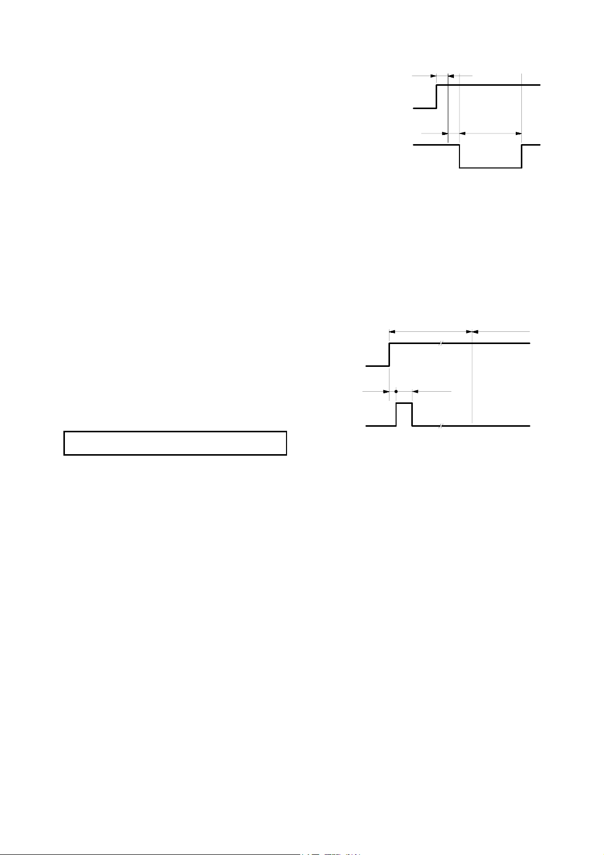
External Test
If your application requires periodic testing more
often than every 2 seconds an external control
system is able to initiate an external test with the
External test function. If a signal of 17 VDC to Vs
is applied to the External test input at least 15 ms,
a self-test starts and the outputs turn to the OFFstate in 15 ms. If no failure is detected, the outputs
return to the ON-state after a maximum of 150 ms.
External test
in
ut
Control
uts
out
H
L
(open)
Approx. 15 ms
H
(open)
L
Failure detection and restoration
When a failure is detected through the tests above, the F3S-B keeps the outputs in the OFF-state and the
indicators show the type of failure, refer to section “8 Troubleshooting”. After the failure is eliminated, in
most cases the F3S-B operation will be restored automatically.
1-3-3 Instability Output
When the received light is insufficient, the instability output and the instability indicator turn ON. In normal
operation, both are OFF. See also “1-8 Indicators”.
This output makes it possible for customers to monitor deterioration of optical performance due to aging or
other factor, such as reduction of LED power, misalignment between the emitter and receiver, or dust on
the lens.
Also, when a failure is detected, or the F3S-B is
connected with the F39-E1 interface unit, the
instability output turns ON as well.
Note: After the power is turned ON, the instability
output goes to the ON-state for approximately 150 ms as shown in the timing chart
for Interlock mode selection.
Power
supply
Instability
output
H
L
Approx.
30 ms
H
L
2 s max.
(Startup waiting time)
Approx.
150 ms
> 15 ms
150 ms max.
F3S-B available
1-4 Optional Functions
These functions can be activated by the optional function software, F39-U1E (see the F39-U1E manual for
detailed information).
Note: The F39-U1E Optional Function Software is used with the F39-E1 Interface Unit, a PC (running
Microsoft
Windows
95, Windows98 or Windows NT
), the F39-JB1C Interface Cable, and a RS-
232C cable.
1-4-1 Start Interlock
When the Start interlock function is used, the F3S-B does not go to the ON-state automatically after power
ON. Interrupting one or more axes resets the start interlock condition, so the F3S-B can start normal operation.
1-4-2 Relay Monitoring
MPCEs (Machine Primary Control Elements) are usually relays or contactors used to control hazardous
movement directly. The state of the MPCEs can be checked with the Relay monitoring function.
A voltage of 17 VDC to Vs has to be applied to the Relay monitoring input through the NC contacts of the
MPCEs when the F3S-B control outputs are in the OFF-state (see “2-3-2 Wiring diagram”). To ensure this
logic relation, the MPCEs must be safety approved types, with forcibly guided contacts.
1-4-3 Blanking
With this function, one or more axes can be disabled. To select the blanking axes, a manual setting function or teaching function is available. This function is useful when part of the F3S-B detection zone is interrupted.
9
F3S-B
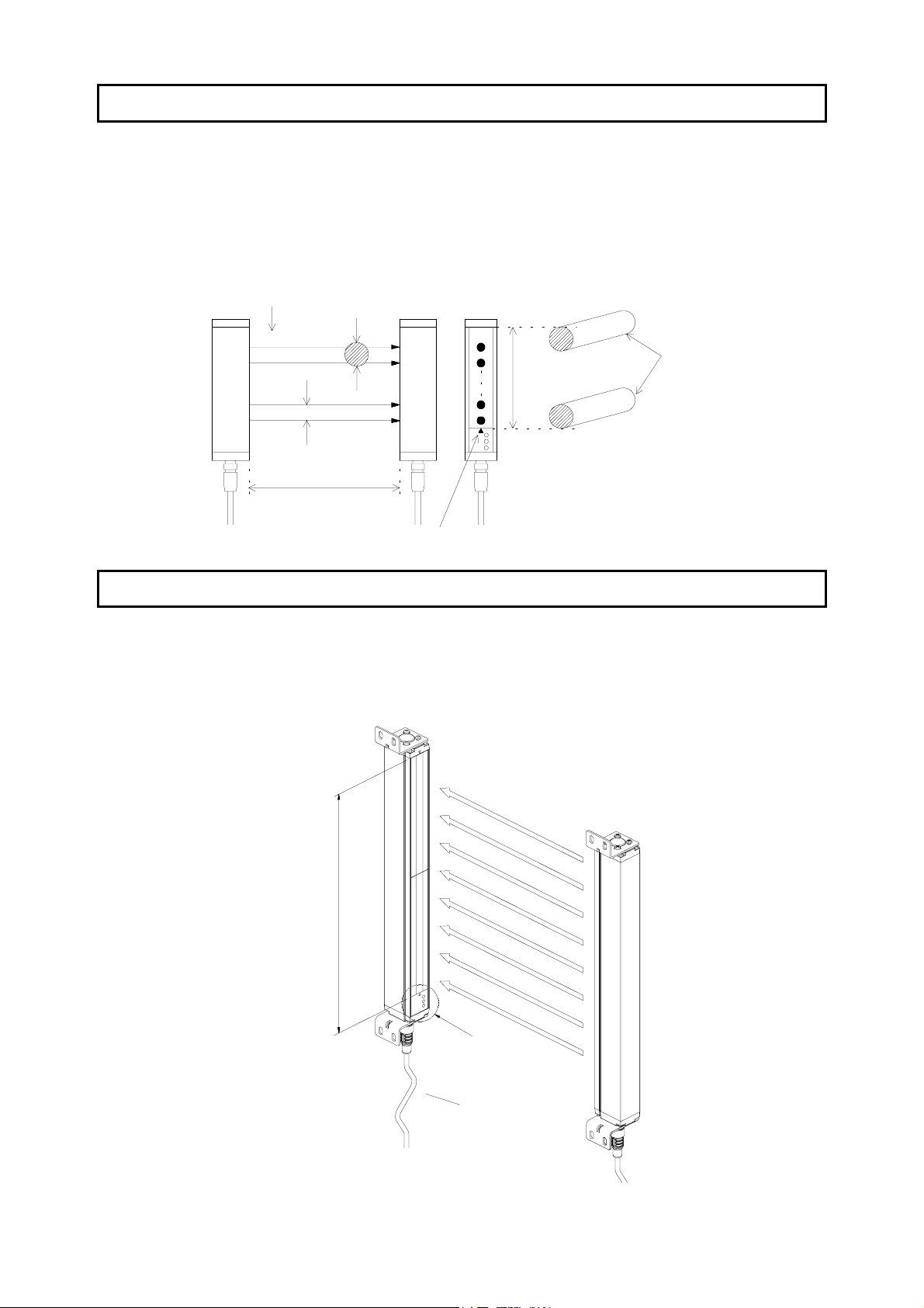
1-5 Detection zone
Protective height
The F3S-B can detect in the area indicated by “Protective height” in the figure below. The protective height
is from “the Optical-axis line mark above the indicator area” to “the end of the yellow metal case”.
Optical-axis line mark
The center line for optical axes is indicated by the triangle mark. This position is a reference line for measuring safety distance.
No. of optical axes
n
n-1
2
Emitter
1
Detection distance
Optical resolution
Optical-axis
pitch
Receiver
Protective
height
Limit position
for detection
Optical-axis
line mark
1-6 Configuration variation
1-6-1 Stand-alone type
This is the most common configuration, and it is used to protect a hazardous part of a machine when approached from one direction only.
Receiver
Emitter
Protective height
10
Indicator area
Extension cable
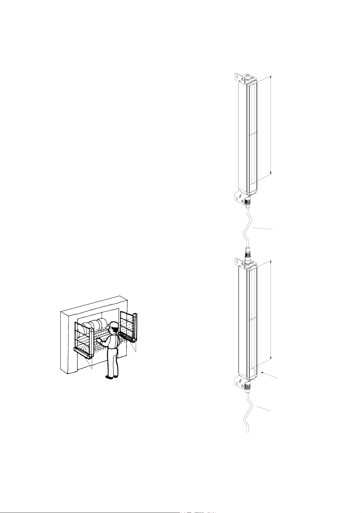
1-6-2 Series connection types
When your application requires an additional protective zone, for example, to prevent someone
from staying behind a primary detection zone, the
F3S-B may be connected in series. The system
consists of a master unit, a slave unit, and a series
connection cable, type F39-JB1B (refer to “2-3-2
Wiring diagram” and “7 Accessories (Optional)”).
The series connection allows up to 96 axes and
2.4 m of protective height in total.
Series connection types have the same characteristics as a stand-alone types. When the detection
zone of the master unit or that of the slave unit is
interrupted, the outputs of the master unit go to the
OFF-state.
However, please note that a slave unit does not
have indicators.
Note: Both the master unit and the slave unit need
to be ordered separately.
F3S-B
Slave unit
Protective height
Emitters
Series connection cable
Master unit
Protective height
Receivers
Indicator area
Extension cable
11

F3S-B
1-7 Ratings and Performance
Type
Item
No. of optical axes
Optical-axis pitch
Optical resolution
(Detection capability)
Protective height
Detection distance
Response time
Startup waiting
time
Supply voltage: Vs
Current
consumption
Light source
Effective
aperture angle
Operating mode
Control output
Instability output
Protection circuit
Start/restart
interlock function
External
test function
Relay monitoring
function (Optional)
Start interlock
function (Optional)
Blanking function
(Optional)
Indicators
Connection
method
Ambient
temperature
Ambient humidity
Insulation
resistance
Dielectric strength
voltage
F3S-BP (*1)
Stand-alone
12 to 66 6 to 33 4 to 22 12 to 66 6 to 33 4 to 22 12 to 30 6 to 15 4 to10
25 mm 50 mm 75 mm 25 mm 50 mm 75 mm 25 mm 50 mm 75 mm
Non-transparent: in diameter
30 mm 55 mm 80 mm 30 mm 55 mm 80 mm 30 mm 55 mm 80 mm
300 / 450 / 600 / 750 / 900 / 1,050 / 1,200 / 1,350
/ 1,500 / 1,650 mm
0.3 to 5.0 m
ON to OFF : See “1-10 Table of Response Time”
OFF to ON (*2): Default 100 ms (selectable with F39-U1E, 80 to 400 ms)
2 s max.
24 VDC ± 20% (including 5 Vp-p ripple)
400 mA max. (under no-load conditions)
Infrared LED (880 nm wavelength). Lifetime: 50,000 hrs. at 25 °C.
Within ± 5° for the emitter and receiver at a detection distance of at least 3 m
according to IEC 61496-2
Light ON
Two PNP transistor outputs, operational current (load current) 200 mA max., re-
sidual voltage 2 V max. (except for voltage drop due to cable extension)
PNP transistor output (not safety-related control output),
load current 100 mA max., residual voltage 2 V max. (except for voltage drop due
to cable extension)
Output short-circuit protection, power supply reverse connection protection
Mode selection before power ON by connecting “Interlock selection input” line to:
Active : No connection or 0 to 2.5 VDC, 3 mA max.
Inactive : Instability output line
Reset of start/restart interlock by connecting “Interlock selection input” line to:
Interlock reset : 17 VDC to Vs, 20 mA max. Duration time 15 to 2,500 ms
Mode selection by connecting “External test input” line to:
Active : 17 VDC to Vs, 10 mA max. Duration time at least 15 ms
Inactive : No connection or 0 to 2.5 VDC, 2 mA max.
Default inactive, selectable with F39-U1E
Relay monitoring input line with NC contact connected,
Available level : 17 VDC to Vs, 10 mA max.
Allowed relay delay time (*2) : Selectable between 20 and 300 ms
Termination when not selected : No connection or 0 to 2.5 VDC, 2 mA max.
Default inactive, selectable with F39-U1E
Default inactive, selectable with F39-U1E
See “1-8 Indicators” No indicators
For Extension cable : 8 pins, M12 connector
For Series connection cable : 6 pins, M12 connector
During operation : –10 to 55 °C (with no freezing)
During storage : –25 to 70 °C
During operation : 35 to 85 %RH (with no condensation)
During storage : 35 to 95 %RH
20 MΩ min. (at 500 VDC)
1,000 VAC 50/60 Hz for 1 min
F3S-BMP (*1)
Master unit for series
connection
F3S-BS (*1)
Slave unit for series
connection
300 / 450 / 600 / 750 mm
12

F3S-B
Type
Item
Degree of
protection
Vibration
resistance
Shock resistance
F3S-BP (*1)
Stand-alone
F3S-BMP (*1)
Master unit for series
connection
F3S-BS (*1)
Slave unit for series
connection
IEC60529 IP65
Normal operation : 10 to 55 Hz, double-amplitude: 0.7mm, X, Y and Z directions
20 sweeps
Normal operation : 100 m/s2 [10 G], X, Y and Z directions: 1000 times
Case: Aluminum
Materials
Front cover: PMMA (acrylic resin)
End caps: PA6
Size
(cross section)
Accessories
Applicable
standard
30 x 40 mm
Test rod (*3), mounting brackets (top and bottom), mounting brackets (intermediate) (*4), mounting plates (*4), Instruction manual(*5)
IEC(EN)61496-1 TYPE 2 ESPE (Electro-Sensitive Protective Equipment)
IEC 61496-2 TYPE 2 AOPD (Active Opto-electronic Protective Devices)
*1 For detailed type names and optical specifications, see “1-9 Table of Types”.
*2 Nominal value (Set time). The accuracy is – 0 / + 70% of ON to OFF response time.
*3 Only with F3S-B2P and BM2P.
*4 For the 1,050 mm protective height and longer types.
*5 Only with F3S-BP and BMP.
1-8 Indicators
Emitter
Receiver
IR-power indicator
Interlock indicator
External test/ blanking indicator
ON-state indicator
OFF-state indicator
Instability indicator
<Emitter Indicators>
POWER
INTER-
LOCK
EXT.TEST/
BLANKING
Optical-axis line mark
IR-power indicator
(Orange)
Interlock indicator
(Yellow)
External test /
blanking indicator
: Lit when emitting.
: Lit during start/restart interlock and start interlock.
: Lit during external test. / Flashing when using blanking
function.
: Lit when receiving light.
: Lit with interrupted light.
Flashing during connection with F39-E1 or with failure.
: Lit with an insufficient light reception or failure.
Flashing during connection with F39-E1.
<Receiver Indicators>
ON
OFF
UNSTAB
ON-state indicator
(Green)
OFF-state indicator
(Red)
Instability indicator
(Orange)
13

F3S-B
1-9 Table of Types
Type Naming Rule
F3S - B M 36 2 P 12 - L
blank
M
S
36
2
5
7
blank
P
blank
12
blank
L
D
Stand-alone Master unit Slave unit Optical
F3S-B122P F3S-BM122P F3S-BS122 30 mm 12 300 mm 0.9 kg
F3S-B182P F3S-BM182P F3S-BS182 18 450 mm 1.2 kg
F3S-B242P F3S-BM242P F3S-BS242 24 600 mm 1.5 kg
F3S-B302P F3S-BM302P F3S-BS302 30 750 mm 1.8 kg
F3S-B362P F3S-BM362P 36 900 mm 2.1 kg
F3S-B422P F3S-BM422P 42 1,050 mm 2.5 kg
F3S-B482P F3S-BM482P 48 1,200 mm 2.8 kg
F3S-B542P F3S-BM542P 54 1,350 mm 3.1 kg
F3S-B602P F3S-BM602P 60 1,500 mm 3.4 kg
F3S-B662P F3S-BM662P 66 1,650 mm 3.7 kg
F3S-B065P
F3S-B095P F3S-BM095P F3S-BS095 9 450 mm 1.2 kg
F3S-B125P F3S-BM125P F3S-BS125 12 600 mm 1.5 kg
F3S-B155P F3S-BM155P F3S-BS155 15 750 mm 1.8 kg
F3S-B185P F3S-BM185P 18 900 mm 2.1 kg
F3S-B215P F3S-BM215P 21 1,050 mm 2.5 kg
F3S-B245P F3S-BM245P 24 1,200 mm 2.8 kg
F3S-B275P F3S-BM275P 27 1,350 mm 3.1 kg
F3S-B305P F3S-BM305P 30 1,500 mm 3.4 kg
F3S-B335P
F3S-B047P F3S-BM047P F3S-BS047 80 mm 4 300 mm
F3S-B067P F3S-BM067P F3S-BS067 6 450 mm 1.2 kg
F3S-B087P F3S-BM087P F3S-BS087 8 600 mm 1.5 kg
F3S-B107P F3S-BM107P F3S-BS107 10 750 mm 1.8 kg
F3S-B127P F3S-BM127P 12 900 mm 2.1 kg
F3S-B147P F3S-BM147P 14 1,050 mm 2.5 kg
F3S-B167P F3S-BM167P 16 1,200 mm 2.8 kg
F3S-B187P F3S-BM187P 18 1,350 mm 3.1 kg
F3S-B207P F3S-BM207P 20 1,500 mm 3.4 kg
F3S-B227P F3S-BM227P 22 1,650 mm
$ Stand-alone
$ Master unit for series connection
$ Slave unit for series connection
$ No. of optical axis (4-66)
$ 25mm optical pitch
$ 50mm optical pitch
$ 75mm optical pitch
$ Slave unit
$ PNP outputs
$ Stand-alone or slave unit
$ No. of optical axis of the connected slave unit
for 25mm optical pitch type : 12, 18, 24, or 30
for 50mm optical pitch type : 06, 09, 12, or 15
for 75mm optical pitch type : 04, 06, 08, or 10
$ Complete set of emitter and receiver
$ Emitter unit only
$ Receiver unit only
resolution
No. of
optical
axes
Protective
height
Weight
(without
accessories)
F3S-BM065P F3S-BS065 55 mm 6 300 mm 0.9 kg
F3S-BM335P 33 1,650 mm 3.7 kg
0.9 kg
3.7 kg
14

F3S-B
1-10 Table of Response Time
1-10-1 Stand-alone type
F3S-B122P
Response
time [ms ]
20
F3S-B065P
F3S-B182P 20 F3S-B095P 20 F3S-B067P 20
F3S-B242P 20 F3S-B125P 20 F3S-B087P 20
F3S-B302P 23 F3S-B155P 20 F3S-B107P 20
F3S-B362P 27 F3S-B185P 20 F3S-B127P 20
F3S-B422P 30 F3S-B215P 21 F3S-B147P 20
F3S-B482P 34 F3S-B245P 22 F3S-B167P 20
F3S-B542P 37 F3S-B275P 24 F3S-B187P 20
F3S-B602P 41 F3S-B305P 26 F3S-B207P 20
F3S-B662P
45
F3S-B335P
1-10-2 Series connection types
The following chart shows the response time of combinations of a master unit and a slave unit connected
in series. For example, the response time of the combination of F3S-BM122P30 and F3S-BS302 is 30 ms.
Slave unit
Master unit
F3S-BM122P
F3S-BS122 F3S-BS182
20 23 27 30
F3S-BM182P 23 27 30 34
F3S-BM242P 27 30 34 37
F3S-BM302P 30 34 37 41
F3S-BM362P 34 37 41 45
F3S-BM422P 37 41 45 49
F3S-BM482P 41 45 49 54
F3S-BM542P 45 49 54 57
F3S-BM602P 49 54 57 61
F3S-BM662P
Slave unit
Master unit
54 57 61 65
F3S-BS065 F3S-BS095 F3S-BS125 F3S-BS155
F3S-BM065P 20 20 20 21
F3S-BM095P 20 20 21 22
F3S-BM125P 20 21 22 24
F3S-BM155P 21 22 24 26
F3S-BM185P 22 24 26 28
F3S-BM215P 24 26 28 30
F3S-BM245P 26 28 30 32
F3S-BM275P 28 30 32 34
F3S-BM305P 30 32 34 35
F3S-BM335P 32 34 35 37
Slave unit
Master unit
F3S-BM047P
F3S-BS047
20 20 20 20
F3S-BM067P 20 20 20 20
F3S-BM087P 20 20 20 20
F3S-BM107P 20 20 20 20
F3S-BM127P 20 20 20 21
F3S-BM147P 20 20 21 23
F3S-BM167P 20 21 23 24
F3S-BM187P 21 23 24 25
F3S-BM207P 23 24 25 26
F3S-BM227P
24 25 26 27
Response time [ms]
F3S-BS067 F3S-BS087 F3S-BS107
Response
time [ms ]
20
F3S-B047P
28
F3S-B227P
F3S-BS242 F3S-BS302
Response
time [ms ]
20
21
15

F3S-B
WIRING and MOUNTING Section 2
2-1 Installation Conditions
WARNING
Do not use the F3S-B on machines that can not be stopped by electrical control in case of an emergency.
Do not use the F3S-B in flammable or explosive environments.
2-1-1 Detection Zone and Intrusion Path
WARNING
Install protective structures around a machine so that you must pass through the detection zone to reach
a hazardous part of the machine.
Install the F3S-B so that some part of the operator’s body remains in the detection zone at all times
when the operator works in a hazardous area.
Failure to do so may result in serious injury.
Correct installation
A hazardous part of a
machine can be reached only
by passing through the
sensor detection zone.
Incorrect installation
A hazardous part of a
machine can be reached
without passing through the
sensor detection zone.
!
!
!!
2-1-2 Safety Distance
Some part of the operator’s
body remains in the detection
zone while they are working.
A worker is between the
sensor detection zone and a
hazardous part of a machine.
!
!
!!
WARNING
Always maintain the safety distance between the F3S-B and a hazardous part of a machine. Serious
injury may result if the machine does not stop before someone reaches the hazardous part.
The “Safety distance” is the minimum distance that must be maintained between the F3S-B and a hazardous part of a machine in order to stop the machine before someone or something reaches it.
The calculation of safety distance varies according to with national standards and individual machine
standards. It also depends on the direction of intrusion to the detection zone of the light curtain, perpendicular, parallel, or angled approach, and depends on the application, e.g. non-industrial applications
where children are present.
See related standards for more details.
16

F3S-B
Using EN 999 Formula
#
Safety distance is calculated based on the following equation.
S = K x T + C (1)
S : Safety distance
K : Intrusion speed into the detection zone
T : Total response time for the machine and light curtain
C : Additional distance calculated or defined based on the optical resolution of the light curtain
When safety distance is not provided by European standards for individual machine, the distance can be
calculated using EN 999.
Calculation for intrusion perpendicular to the detection zone
1) 30 mm optical resolution type
Substitute K = 2,000 mm/s and C = 8 (d-14 mm) in equation (1) and calculate as shown below.
where:
S = safety distance (mm)
Tm = machine response time (s) (see Note 2)
Ts = light curtain response time (s) (see Note 3)
d = optical resolution of light curtain (mm)
e.g.:
Use S = 100 mm if the result of equation (2)
Recalculate using the following equation with K = 1,600 mm/s if the result is over 500 mm.
Use S = 500 mm if the result from equation (3) is 500 mm or less.
2) 55 mm and 80 mm optical resolution type
Substitute K =1,600 mm/s and C = 850 mm in equation (1) and calculate as shown below:
Note:
1. EN 999 : European Standard. Safety of machinery – The positioning of protective equipment in
2. The machine response time (Tm) refers to the maximum time from the moment the machine receives
3. The light curtain response time (Ts) refers to the time required for output changing from ON to OFF.
S = 2,000 mm/s x ( Tm + Ts ) + 8 ( d - 14 mm ) (2)
Tm = 0.05 s, F3S-B122P (Ts = 0.02 s, d = 30 mm)
S = 2,000 mm/s x ( 0.05 s + 0.02 s) + 8 (30 mm-14 mm)
= 268 mm
S = 1,600 mm/s x ( Tm + Ts ) + 8 ( d – 14 ) mm (3)
S =1,600 mm/s x ( Tm + Ts ) + 850 mm
respect of approach speeds of parts of the human body
a stop signal to the moment a hazardous part of the machine stops. The machine response time
should be measured and confirmed periodically.
(See Note 1)
is 100 mm or less.
Hazardous
part
Safety distance
Detection
zone
Optical-axis line
Intrusion
direction
17

F3S-B
4.
Using ANSI/RIA R15.06 Formula
#
Safety distance is calculated based on the following equation when a person moves perpendicular to the
detection zone of a light curtain.
S = K x ( Ts + Tc + Tr ) + Dpf (4)
S : Safety Distance (mm)
K : Speed constant of 1,600 mm/s (63 inches/s) minimum based on the movement being the
hand/arm only and the body being stationary.
A greater value may be required in specific applications and when body motion must also be
considered.
Ts : Worst stopping time of machine/equipment
Tc : Worst stopping time of the control system.
Tr : Maximum response time of the light curtain (see Note 5)
Dpf : Depth penetration factor.
Additional distance calculated or defined based on the optical resolution of the light curtain
Calculation for intrusion perpendicular to the detection zone
1) 30 mm and 55 mm optical resolution type
Substitute K = 1,600 mm/s and Dpf = 3.4 x ( Os – 6.875 mm ) in equation (4) and calculate as shown below.
S = 1,600 mm/s x ( Ts + Tc + Tr ) + 3.4 x ( Os – 6.875 mm ) (5)
where:
S = safety distance (mm)
Os = object sensitivity ( =optical resolution) of light curtain (mm) (see Note 6)
e.g.:
Ts + Tc = 0.06 s, F3S-B542P (Tr = 0.037 s, Os = 30 mm )
S = 1,600 mm/s x ( 0.06 s + 0.037 s ) + 3.4 x ( 30 mm – 6.875 mm )
= 234 mm
2) Flashing when receiving light in start/restart interlock.80 mm optical resolution type
Substitute K =1,600 mm/s and Dpf = 900 mm in equation (4) and calculate as shown below:
S =1,600 mm/s x ( Ts + Tc + Tr ) + 900 mm (6)
Note:
4. ANSI/RIA R15.06 1999 : American National Standard for Industrial Robots and Robot Systems Safety
Requirements
5. The light curtain response time (Tr) refers to the time required for output changing from ON to OFF.
6. When the optional blanking function is used, the entire (from emitter to receiver) blanked area should be
physically filled. Otherwise, d must be calculated as follows:
Os = (Size of the largest blanked area ) + (Original optical resolution)
(See Note 4)
18

F3S-B
2-1-3 Distance from Reflective Surfaces
WARNING
Be sure to install the F3S-B to minimize the effects of reflection from reflective surfaces.
Failure to do so will cause detection to fail and may result in serious injury.
Install the F3S-B with minimum Distance D shown below from reflective surfaces (highly reflective surfaces) like metal walls, floors, ceilings, and work pieces.
<Side View>
Reflecting ceiling
Reflecting surface
<Top View>
Emitter Receiver
Detection zone
D
L
D
Reflecting floor
D
5°
Emitter Receiver
5°
L
Distance between emitter and
receiver (detection distance L)
Minimum installation
distance D
0.3 to 3 m 0.27 m
3 to 5 m L x tan 5° = L x 0.087 (m)
2-1-4 How to Prevent Mutual Interference
Take action to prevent mutual interference when two or more sensors are installed. The following figures
show configurations in which mutual interference may occur.
(Incorrect) (Incorrect)
Emitter 1
RS-485
Emitter 1
Emitter 2
Receiver 1
(Incorrect)
Emitter 2
Receiver 2
RS-485
Receiver 1
Receiver 2
Emitter 1Emitter 2
Receiver 1
Receiver 2
RS-485
19

F3S-B
Correct installations are shown below to prevent mutual interference.
• Alternate emitters and receivers
(Correct)
(Correct)
Receiver 1
Receiver 1
Emitter 2
RS-485
Emitter 1
(Correct)
Emitter 2
Receiver 2
RS-485
Emitter 1
Receiver 2
Emitter 1
Receiver 2
Receiver 1
RS-485
Emitter 2
RS-485
• Install barriers
(Correct)
Emitter 1
RS-485 RS-485
Receiver 1
Emitter 2
Receiver 2
• Keep enough distance between each set of sensors
Arrange the sets so that distance between their protective height marks is greater than “D” in the following
table.
(Correct)
L
Emitter 1
D
Emitter 2
RS-485
Receiver 1
Receiver 2
Distance between emitter and receiver
(detection distance L)
0.3 to 3 m 0.54 m
3 to 5 m L x tan 10° = L x 0.18 (m)
20
Emitter 1
Emitter 2
(Correct)
10°
D
10°
L
Minimum installation
distance D
Receiver 1
Receiver 2

2-2 Dimensional Drawings
2-2-1 F3S-B
• Side Mounting
4-MOUNTING HOLES
MOUNTING BRACKET
(TOP AND BOTTOM)
MOUNTING BRACKET
(INTERMEDIATE)
(note 4)
2-MOUNTING HOLES
F3S-B
D
C
B
A (PROTECTIVE HEIGHT)48
54.25 25
M12 CONNECTOR
(note 2, 3)
2-M5 (note 1)
4-M5
20
15 (note 1)
E (note 1)
28 (note 1)
MOUNTING SCREW HOLES
28
OPTICAL AXIS
E (note 1)
D
40.3
8
20.336
15
30
(59.6)
Type A
Protective
height
F3S-B122, B065, B047 300 343 387 371 ----F3S-B182, B095, B067 450 493 537 521 ----F3S-B242, B125, B087 600 643 687 671 ----F3S-B302, B155, B107 750 793 837 821 ----F3S-B362, B185, B127 900 943 987 971 ----F3S-B422, B215, B147 1050 1093 1137 1121 560.5
F3S-B482, B245, B167 1200 1243 1287 1271 635.5
F3S-B542, B275, B187 1350 1393 1437 1421 710.5
F3S-B602, B305, B207 1500 1543 1587 1571 785.5
F3S-B662, B335, B227 1650 1693 1737 1721 860.5
B
Full length of
the sensor
C
Full length
with brackets
D
Mounting hole
center width
Intermediate
mounting
bracket
position
Unit: mm
E
21

F3S-B
• Rear Mounting (with Intermediate Mounting Bracket)
55.3
MOUNTING BRACKET
(INTERMEDIATE)
(note 4)
C
40.3
15
2-M5 (note 1)
15 (note 1)
D
E (note 1)
4-M5
B
M12 CONNECTOR
(note 2, 3)
MOUNTING BRACKET
(TOP AND BOTTOM)
4-MOUNTING HOLES
2-MOUNTING HOLES
OPTICAL AXIS
MOUNTING PLATE
(SEE "2-2-3 Mounting plate")
24
E (note 1)
42.74
30
A (PROTECTIVE HEIGHT)
2554.25
48
11.25 D
20
24 (note 1)
MOUNTING SCREW HOLES
32 (29.7)
Type A
Protective
height
F3S-B422, B215, B147 1050 1093 1143.5 1121 560.5
F3S-B482, B245, B167 1200 1243 1293.5 1271 635.5
F3S-B542, B275, B187 1350 1393 1443.5 1421 710.5
F3S-B602, B305, B207 1500 1543 1593.5 1571 785.5
F3S-B662, B335, B227 1650 1693 1743.5 1721 860.5
B
Full length of
the sensor
C
Full length
with brackets
D
Mounting hole
center width
Intermediate
mounting
bracket
position
22
Unit: mm
E

• Rear Mounting (without Intermediate Mounting Bracket)
F3S-B
50.3
C
40.3
10
MOUNTING BRACKET
(TOP AND BOTTOM)
4-MOUNTING HOLES
D
OPTICAL AXIS
B
A (PROTECTIVE HEIGHT)
2554.25
48
D
4-M5
20
MOUNTING SCREW HOLES
M12 CONNECTOR
(note 2, 3)
Unit: mm
Type A
Protective
height
B
Full length of
the sensor
C
Full length
with brackets
Mounting hole
center width
F3S-B122, B065, B047 300 343 387 371
F3S-B182, B095, B067 450 493 537 521
F3S-B242, B125, B087 600 643 687 671
F3S-B302, B155, B107 750 793 837 821
F3S-B362, B185, B127 900 943 987 971
D
36
30
8
23

F3S-B
Note:
1. The intermediate bracket and mounting screw holes are only applied to types which have a protective
height of 1050 mm or longer.
2. The master unit has an M12 connector on both ends of the sensor (for the extension cable and the series connection cable).
3. Keep the following distance for the extension cable and the series connection cable when the cable is
bent.
Series connection cord
of the Master unit side
and Slave unit side
81 min.
Extension cord
73 min.
4. The figures on the previous pages show the L-shaped intermediate bracket (see 2-2-4) on the left side
of the F3S-B. In case the L-shaped intermediate bracket needs to be on the right side of the sensor, the
intermediate mounting bracket needs to be oriented upside down as shown the figure below. The position of the mounting screw holes for the L-shaped intermediate bracket changes from left side to right
side. This also applies in the case of side mounting, the figures below show the rear mounting style only.
2-M5
D
15
2-M5
15
D
E
MOUNTING SCREW HOLES MOUNTING SCREW HOLES
24
4-M5
20
4-M5
20
24
24
E

2-2-2 Mounting Bracket (Top and Bottom)
12
16
22
F3S-B
5.5
R2.75
20
20°
°
5
3
46
30
2
R1.75
36
5
.
5
2
ø
5
3.
R4.5
Unit: mm
2-2-3 Mounting Plate
Only supplied with types which have a protective height of 1050 mm or longer.
The mounting plates are only required when the F3S-B is mounted in the rear mounting configuration with
the intermediate brackets.
42.74
36.5
20
6.254
22.5 3
7
5
28.74
5.5
How to use
1. Combine the mounting bracket (top and bottom)
with the mounting plate.
2. Then affix the assembled bracket with M5 screws.
R2.75
Mounting bracket
(top and bottom)
M5 screw
12
Unit: mm
Mounting plate
Sensor
25

F3S-B
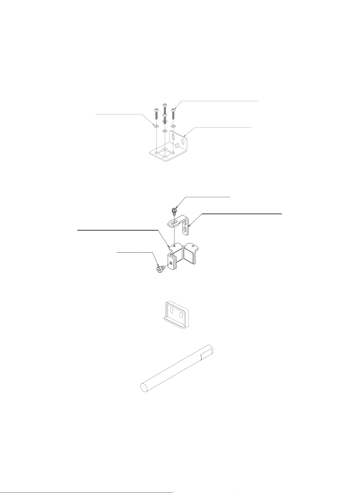
2-2-4 Mounting Bracket (Intermediate)
Only supplied with types which have a protective height of 1050 mm or longer.
MOUNTING SCREW FOR SENSOR (M6x8)
FLAT INTERMEDIATE BRACKET
RUBBER
U-SHAPED INTERMEDIATE BRACKET
FIXING SCREW FOR BRACKET (M4x10)
L-SHAPED INTERMEDIATE BRACKET
Configuration of U-shaped Intermediate Bracket Mounted at 90 Degree Angle
How to use
1. Assembly
Choose the mounting direction for the L- and Ushaped intermediate bracket combination based on
the mounting direction (side or rear) and temporarily
secure the brackets with the M4 x 10 screw.
2. Installation
Clasp the center of the case with the U-shaped
bracket and temporarily secure the bracket to the
F3S-B with the M6 x 8 screw. The mounting bracket
(intermediate) for the emitter is oriented upside down
when compared to the bracket of the receiver.
L-shaped intermediate bracket
U-shaped intermediate bracket
Side mounting
U-shaped intermediate bracket
Unit: mm
Rear mounting
Case
26

F3S-B
2-3 Wiring
WARNING
Do not connect the F3S-B to a power supply with a voltage higher than 24 VDC + 20%.
Do not connect the F3S-B to an AC power source.
2-3-1 Power Supply Units and Loads
WARNING
DC power supply units must satisfy all of the conditions below so that the F3S-B can comply with the
applicable standards IEC 61496-1, and UL 508.
• The power supply voltage should be within rating (24 VDC ± 20 %).
• The power supply is connected only to the F3S-B and to the devices related to the electro-sensitive
protective function of the F3S-B, such as a safety controller and muting sensors, and it has enough
rated current for all the devices. The power supply is not connected to other devices or machines.
• The power supply uses double or reinforced insulation between the primary and secondary circuits
• The power supply has automatic reset characteristics (voltage drop) to protect overcurrent.
• The power supply maintains an output holding time of at least 20 ms.
• FG (frame ground terminal) must be connected to PE (protective earth) when using a commercially
available switching regulator.
• The power supply must have output characteristics required for the power source for Class 2 Circuit
or Limited Voltage/Current Circuit as defined in UL508 (see “Remark”).
• The power supply must conform to regulatory requirements and standards, regarding EMC and elec-
trical equipment safety, of the country where the F3S-B is installed and where machinery will be operated, for example: The EMC Directive (industrial environment) and the Low Voltage Directive in
EU.
[Remark] The power supply must conform to the following requirements (1) or (2) regarding a secondary
circuit, in accordance with UL 508, to avoid a fire.
(1) The power supply includes a limited voltage/current circuit supplied by an isolating source like
the secondary winding of an isolating type transformer. In the limited voltage/current circuit,
- the current available is limited to a value not exceeding 8 A (including the case of
short-circuit), or
- a secondary fuse or other such secondary circuit protective device used to limit the
available current shall be rated at not more than a value 4.2 amperes (for the power
supply voltage of 24 VDC).
(2) The power supply includes a Class 2 circuit supplied by an isolating source that complies
with the requirement in the Standard for Class 2 Power Units, UL 1310, or the requirements
in the Standard for Class 2 and Class 3 Transformers, UL 1585.
Recommended power supply: S82K (15 W, 30 W, 50 W, 90 W type) made by OMRON, UL Listed (UL508,
Power supply and loads must be reinforced insulated or double insulated as shown in the following figure
to protect against electrical shock. The insulation shown in the figure should insulate against hazardous
voltage levels (230 VAC, etc.), not simply against 24 VDC.
Class2 Output) and CE Marked (EMC and Low Voltage Directives)
Relay monitoring input
Emitter
0 V
+24 V
k1
Reinforced insulation or double
insulation between the coil and
contacts, between contacts
Receiver
Power
supply unit
Reinforced
insulation or
double
insulation
Output
0 V
+24 V
k1
K1
Hazardous
voltage level
Hazardous voltage level
Motor, etc.
27

F3S-B
2-3-2 Wiring Diagram
Disconnect all sources of power before wiring the F3S-B to a machine.
Emitter
RS-485(A) (Grey 5)
RS-485(B) (Pink 6)
Receiver
0 V (Blue 7)
Ext. test (Green 3)
Relay monitoring (White 1)
24 VDC (Brown 2)
S1
E1
E1: 24 VDC Power supply
S1: External test switch
K1, K2: Relay or PLC input to control the dangerous movement of a machine
Load: Inductive load with surge suppressor (Note) or resistive load to indicate unstable condition
Interlock selection (yellow 4)
Instability (yellow 4)
Load
0 V (Blue 7)
Output2 (White 1)
24 VDC (Brown 2)
Output1 (Green 3)
K2
K1
When using Start/restart interlock Function When using optional Relay Monitoring Function
Emitter
24 VDC (Brown 2)
Interlock selection
S2
0 V (Blue 7)
(yellow 4)
RS-485(A) (Grey 5)
RS-485(B) (Pink 6)
S3
Receiver
Instability (yellow 4)
(White 1)
Relay monitoring
k1
0 V (Blue 7)
24 VDC (Brown 2)
k2
Emitter
0 V (Blue 7)
Ext. test (Green 3)
24 VDC (Brown 2)
S1
E1
S2: Restart interlock reset switch
S3: Mode change switch for inspection
28
Load
E1
k1, k2: Auxiliary contact to monitor the
condition of the final relay

F3S-B
2-3-3 Wiring Procedure
1. Connect the emitter extension cable (F39-JBA-L optional, gray color outer jacket) to the emitter.
(The emitter uses gray color plastic caps.)
2. Connect the receiver extension cable (F39-JBA-D optional, black color outer jacket) to the receiver.
(The receiver unit uses black color plastic caps.)
3. Connect the 0 V line of the power supply directly to protective earth (PE).
Note: Be sure to wire correctly. Failure to do so may damage the F3S-B.
• Connector (Main Unit End)
Wire Color
of Extension
Cable
Front View Pin No.
Receiver Emitter
1 Control output 2 Relay monitoring input White
7
1
865
2
4
3
2 24 VDC 24 VDC Brown
3 Control output 1 External test input Green
4 Instability output Interlock selection input Yellow
5 RS-485 (A) RS-485 (A) Grey
6 RS-485 (B) RS-485 (B) Pink
7 0 V 0 V Blue
8 N.C. / reserved N.C. / reserved Red
N.C. / reserved: do not connect
• Extension Cable (F39-JBA Optional)
Signal Name
42 L
ø15
M12
Round vinyl-insulated cord
5.7 mm dia. (32/0.1 mm dia.) 8 cores
Type (Set name) for Emitter for Receiver L
F39-JB1A F39-JB1A-L F39-JB1A-D 3000
F39-JB2A F39-JB2A-L F39-JB2A-D 7000
Gray outer
jacket color
F39-JB3A F39-JB3A-L
• Series Connection Cable (F39-JB1B Optional)
48.5
Ø15
M12
Type (Set name) for Emitter for Receiver
F39-JB1B F39-JB1B-L Gray outer
jacket color
Unit: mm
Black outer
jacket color
F39-JB3A-D
300
Unit: mm
10000
F39-JB1B-D Black outer
jacket color
29

F3S-B
ADJUSTMENT Section 3
3-1 Adjustment Procedure
1. Ensure the following points.
• A hazardous part of a machine cannot move during the adjustment.
• The optical surfaces of the emitter and receiver are clean.
• There should be no light-interrupting objects in the F3S-B detection zone.
2. Adjust the torsion angle of the emitter while monitoring the indicator on the receiver and locate the point
where the ON-state indicator (lit: green) is lit and the Instability indicator (UNSTAB: orange) goes OFF.
3. Adjust the torsion angle so that the light-receiving condition becomes as stable as possible. When the
above adjustments have been completed, tighten all brackets and mounting screws while being careful
not to change the optical axis adjustment for the F3S-B. The tightening torque for these screws is shown
in the following table.
Mounting bracket types Screw designation and length (mm) Tightening torque
Mounting brackets
(top and bottom)
(intermediate)
4. If a stable light receiving condition is not obtained through the angle adjustment of the emitter, perform the
following adjustments.
If the Instability indicator does not go OFF, temporarily fix the emitter at the most stable state and
conduct angle adjustment for the receiver according to the procedure described in the above step 2.
5. If a stable light receiving condition is not obtained through the above angle adjustment of the receiver,
check for parallelism between the emitter mounting surface and the receiver mounting surface and also
check if the emitter and receiver are mounted to the same height.
M3 x 10
(tapping screw)
M4 x 10 1.2 N·m (12.2 kg·cm) Mounting brackets
M6 x 8 4.3 N·m (43.9 kg·cm)
0.54 N·m (5.5 kg·cm)
3-2 Check List
Check the following items to make sure the installation is correct
1. % Machine structure does not hinder stop and other safety functions.
2. % Intrusion into a hazardous part of the machine is not possible without passing through the F3S-B detection zone.
3. % Protective structure that allows the F3S-B to detect an operator when he/she works in the hazardous
area.
4. % The actual safety distance is greater than the calculated distance.
5. % Reflective surfaces are not installed in prohibited areas.
Check the following items to make sure wiring is correct before turning ON power.
1. % The power supply is connected only to the F3S-B and to the devices related to the electro-sensitive
protective function of the F3S-B, such as a safety controller and muting sensors, and it has enough
rated current for all the devices.
2. % The power supply unit is a 24-VDC unit that conforms to the EMC Directive, Low-voltage Directive
and output holding specifications.
3. % The polarity of the power supply connection is not reversed.
4. % The emitter extension cable is properly connected to the emitter and the receiver extension cable is
properly connected to the receiver.
5. % Double insulation or reinforced insulation is used between the output and the hazard potential
(commercial power supplies, etc.), and between the Relay monitoring input and the hazard potential.
6. % Outputs are not shorted to the +24V line.
7. % Loads are not connected to the +24V line.
8. % No lines are connected to a commercial power supply.
30

F3S-B
9. % When two or more units are used in close proximity, they are mounted properly to prevent mutual
interference.
Turn ON power to the F3S-B and make sure the F3S-B is operating properly as described below with
the machine stopped.
10. % The F3S-B will begin operating normally within 2 seconds after power is turned ON. When the protective field is free of obstructions, IR-Power indicator (orange) of the emitter and the ON-state indicator (green) of the receiver will light.
11. % A test rod can be detected at any position in the detection zone. In other words, the OFF-state indicator (red) will remain lit and the ON-state indicator (green) will be never lit as long as the test rod is
present in the detection zone.
Detection checkpoints are:
(A) Protective height directly in front of the emitter.
(B) Protective height directly in front of the receiver.
(C) Protective height midway between the emitter and receiver.
* Be sure to use the correct test rod which has the same diameter as the optical resolution of the
F3S-B to be tested.
* Make the start/restart interlock function inactive to carry out this check.
(A)
(C)
(B)
Emitter
Test rod
Receiver
12. % The external test function can be activated and outputs are momentarily turned OFF if the external
test input terminal is connected to a voltage of 17 VDC to Vs.
Operate the machine and check to see if a hazardous part stops under the conditions below.
13. % The hazardous part stops within the calculated time when a test rod is inserted into the detection
zone directly in front of the emitter, directly in front of the receiver and midway between the emitter
and receiver.
14. % The hazardous part remains stopped as long as the test rod is present in the detection zone.
15. % The hazardous part stops when the F3S-B power supply is turned OFF.
16. % The overall measured machine response time is less than the calculated response time.
31

F3S-B
I/O CIRCUIT Section 4
IR-light
indicator
Grey
5
Pink
6
Interlock
indicator
Main emitter
circuit
Ext. test/
blanking
indicator
Brown
2
Green
3
External test
input
White
1
Relay monitoring
input
Yellow
4
Blue
7
Interlock selection
input (*1)
+24 V
0 V
Instability
OFF-state
Pink
Grey
6
5
ON-state
indicator
indicator
Main receiver
circuit
indicator
Brown
2
Green
3
Control output 1
White
1
Control output 2
Yellow
4
Instability
output
Blue
7
Load
Load
Load
RS-485(B)
RS-485(A)
*1 See “2-3 Wiring” for wiring information
32

F3S-B
APPLICATIONS Section 5
5-1 Application (1)
- without Start/restart interlock function
- without Relay monitoring function
R
KM1
KM2
M
M: 3-phase motor
E1: 24 VDC Power supply
S1: External te st switch
KM1, KM2: Electromagnet contactor (with Reinforced insulation)
Note: KM1 and KM2 must have reinforced insula-
tion between the coil and contacts.
Emitter
g
n
i
r
o
t
i
n
o
m
y
a
l
e
Ext. test
Vcc
S1
E1
RS-485(A)
RS-485(B)
Gnd
Interlock selection
Receive r
Instability
Output1
Gnd
Vcc
KM1
Output2
KM2
5-2 Application (2)
- with Start/restart interlock function
- with Relay monitoring function
R
KM1
KM2
M
M: 3-phase motor
E1: 24 VDC P ower supply
S1: External te st switch
S2: Restart interlock reset switch
KM1, KM2: Electromagnet contactor (with Reinforced insulation)
Note: KM1 and KM2 must have reinforced insula-
tion between the coil and contacts as well as
between contacts.
Emitter
g
n
i
r
o
t
i
n
o
m
y
a
l
e
Ext. test
Vcc
S1
E1
RS-485(A)
RS-485(B)
Gnd
Interlock selection
S2
Receiver
Instability
Output1
Output2
Gnd
Vcc
KM1
KM2
33

F3S-B
MAINTENANCE Section 6
WARNING
Do not use the F3S-B until the following inspections are completed.
Failure to do so may result in loss of life or serious injury.
Do not disassemble, repair or modify the F3S-B.
Note:
1. For Safety, be sure to record and store inspection results.
2. Make sure you are thoroughly familiar with the F3S-B and the machine prior to conducting an inspection.
3. Make sure all personnel have adequate guidelines for performing maintenance and inspections.
4. Check all items in “3-2 Check List” again if the protective structures preventing access to the hazard
are changed.
6-1 Daily Inspections
Be sure to inspect the following items at the start of work or after a shift change.
1. % No intrusion paths into a hazardous part of a machine except through the F3S-B detection zone.
2. % Some part of the operator’s body remains in the F3S-B detection zone at all times while the operator
works in the hazardous area.
3. % The actual safety distance is greater than the calculated distance.
4. % No dirt or scratches on the optical surface.
Operate the machine and check to see if the hazardous part stops under the conditions below.
5. % The hazardous part moves when there is nothing in the detection zone (normal operation).
6. % The hazardous part stops within the calculated time when the test rod is inserted into the detection
zone directly in front of the emitter, directly in front of the receiver and midway between the emitter
and receiver.
7. % The hazardous part remains stopped as long as the test rod is present in the detection zone.
8. % The hazardous part stops when the F3S-B power supply is turned OFF.
6-2 Inspection Every Six Month
Inspect the following items every six months or when a machine setting is changed.
1. % Machine structure does not hinder stop and safety functions.
2. % There is no machine modification or connection change that will adversely affect the control system.
3. % The F3S-B outputs are correctly wired to the machine.
4. % The actual overall response time of the machine is less than the calculated response time.
5. % The control relay and connector are in good condition.
6. % The brackets are securely tightened.
6-3 Cleaning
If the surface of the F3S-B is extremely dirty, F3S-B will stop activating outputs. In this case, use a clean soft
cloth and clean the surface without pressure. Do not use any solvents such as paint thinners, benzene or
acetone to clean the F3S-B because they will damage the translucent surface.
34

ACCESSORIES (OPTIONAL) Section 7
• F39-JBA Extension Cable : 2 pcs./set
Type Length Specification
F39-JB1A
F39-JB2A
F39-JB3A
• F39-JB1B Series Connection Cable : 2 pcs./set
Type Length Specification
F39-JB1B 300 mm M12 connector (6 pins)
• F39-EU1E Optional Function Kit
The following three accessories, the F39-E1 Interface Unit, the F39-U1E Optional Function Software,
and the F39-JB1C Interface Cable are packed in one package.
• F39-E1 Interface Unit
3 m
7 m
10 m
M 12 connector (8 pins)
F3S-B
• F39-U1E Optional Function Software
Contained on one 3.5 Inch floppy disk and runs with Windows
Hardware requirements: PC/Laptop Pentium
133 (32 MB for Windows
• F39-JB1C Interface Cable
5 m cable length, M8 connector (4 pins)
95, Windows
98 or Windows NT
95, 64 MB for Windows NT
)
35

F3S-B
TROUBLESHOOTING Section 8
The F3S-B runs internal self-tests after the power is turned ON and while the F3S-B is in normal operation. The external test is also available. If a failure is detected, a corresponding flicker pattern is indicated
by the red LED (OFF-state indicator) of the receiver. Each failure indication sequence, other than continuous flashing, will repeat after a two-second interval. This repetition will continue until a remedy is effected.
Indication Cause Remedy
Flashing
continuously
Flashing
once
Flashing
twice
Flashing
three times
Flashing
four times
Flashing
five times
Flashing
six times
Flashing
seven times
Relay monitoring failure during
ON-state
(In the case that the Relay monitoring function is activated, the
wrong status of the relay NC contact is detected when the control
outputs are in the ON-state.)
Internal parameter failure of a
receiver
Communication failure between
an emitter and receiver,
or internal failure of an emitter
Internal memory failure of a
receiver
Relay monitoring failure during
OFF-state
(In case that Relay monitoring
function is activated, wrong status
of the relay NC contact is detected
when the control outputs are OFFstate.)
Control output failure
(High level voltage is detected
although a control output is in
OFF-state.)
Internal hardware failure of a
receiver
Series connection system failure of receivers
0.5 sec 0.5 sec
N times flashing
2 sec
− Check connection of the relay monitoring input.
− Check the voltage of the relay monitoring input.
(When control outputs are ON-state, the relay monitoring input must show 0 V )
* Regarding only this failure, the interruption and
restoration of power is necessary to restore F3S-B.
− Change the setting parameters by the optional soft-
ware F39-U1E, or reset the setting parameters to
factory setting status also by F39-U1E.
− Replace the receiver.
− Check connection of the emitter and the receiver.
− Check series connection of the emitters.
− Check if the emitter and the receiver have the same
type name.
− Check if the type name of the slave unit emitter is
same as the indicated one on the label of the master unit emitter
− Replace the emitter.
− Replace the receiver.
− Check connection of relay monitoring input.
− Check the voltage of the relay monitoring input.
(When control outputs are OFF, the relay monitoring
input must be at a level of 17 VDC to Vs.)
− Check connection of control outputs for a short cir-
cuit with Vs (cables, connected devices)
− Replace the receiver.
− Replace the receiver.
− Check series connection between the receivers.
− Check if the type name of the slave unit receiver is
same as the indicated one on the label of the master unit receiver
− Replace the master unit receiver and /or the slave
unit receiver.
36
Fig. Timing Chart for flashing pattern of red LED (OFF-state indicator)

OMRON Corporation
Industrial Automation Company
Industrial Sensors Division
Sensing Devices and Components Div. H.Q.
Shiokoji horikawa
Shimogyo-ku, Kyoto 600-8530
JAPAN
Tel: +81-75-344-7068 / Fax: +81-75-344-7107
OMRON EUROPE SENSOR BU
Carl-Benz-Str.4
71154 Nufringen
GERMANY
Tel: +49-7032-811-0 / Fax: +49-7032-811-199
OMRON ELECTRONICS, INC.
1 East Commerce Drive, Schaumburg, IL 60173
U.S.A.
Tel: +1-847-843-7900 / Fax: +1-847-843-7787
OMRON ASIAPACIFIC PTE. LTD.
83 Clemenceau Avenue, #11-01, UE Square,
Singapore 239920
SINGAPORE
Tel: +65-835-3011 / Fax: +65-835-2711
Authorised Distributor:
Cat. No. E502-E2-01 Note: Specifications subject to change without notice ©OMRON Corporation 2001 All Rights Reserved.
Part No. 7490-00098 Rev. A2 Printed in Germany
 Loading...