

Omron F3S-B DATASHEET
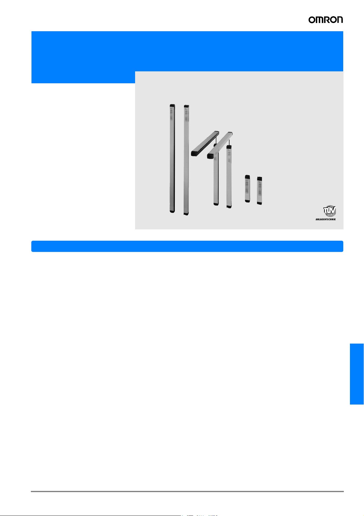
Safety Light Curtain
F3S-B
Suitable for
Detecting Human
Bodies in a
Dangerous Area
Safety Design for Category 2.
Features
• The F3S-B is a type 2 Safety Light curtain intended to be
used as or with the safety related parts of the control system
of a machine to category 2, 1 or B as defined in the European standard EN954-1.
• Compliance with IEC 61496-2, EN 61496-1 standards and
machine and EMC directive.
• Received certificates from Notified Bodies as Type 2 ESPE
(Electro-Sensitive-Protective-Equipment).
• UL/CSA approved.
• Pursuing safety with high level of safety design and FMEA.
• Series configuration of two units is possible.
• Units available with an axis pitch of 25 mm (hand protection), 50 mm (arm protection) or 75 mm (body protection) in
protective height ranging from 300 mm to 1650 mm.
• Human body detection system without a dedicated control
box.
• M12 Connector
F3S-B
G-31F3S-B
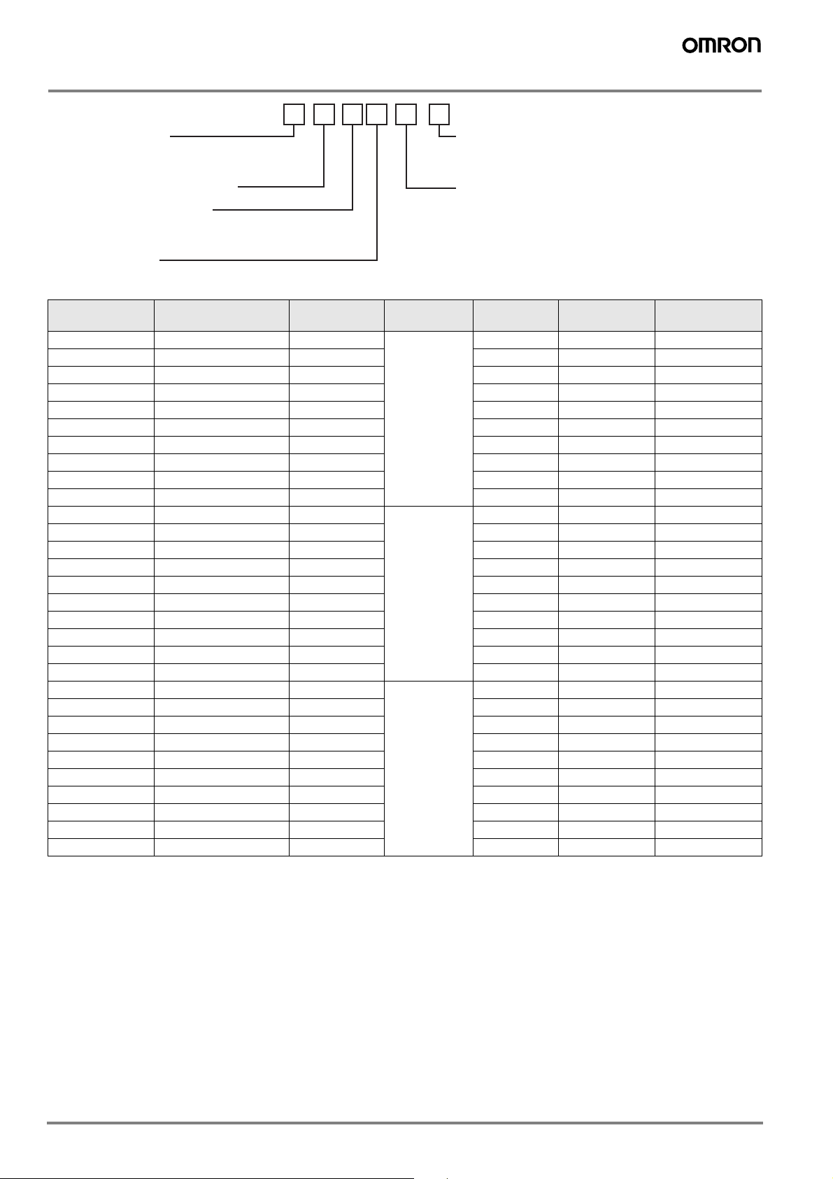
Ordering Information
F3S-B M 36 2 P 12 - L
blank Stand-alone
M Master unit for series connection
S Slave unit for series connection
36 No. of optical axis (4-66)
2 25 mm optical pitch
5 50 mm optical pitch
7 75 mm optical pitch
blank Slave unit
P PNP outputs
blank Complete set of emitter and receiver
L Emitter unit only
D Receiver unit only
blank Stand-alone or slave unit
12 No. of optical axis of the connected slave unit
for 25 mm optical pitch type: 12, 18, 24, or 30
for 50 mm optical pitch type: 06, 09, 12, or 15
for 75 mm optical pitch type: 04, 06, 08, or 10
Stand-alone Master unit Slave unit Optical
resolution
F3S-B122P F3S-BM122P
F3S-B182P F3S-BM182P
F3S-B242P F3S-BM242P
F3S-B302P F3S-BM302P
F3S-B362P F3S-BM362P
F3S-B422P F3S-BM422P
F3S-B482P F3S-BM482P
F3S-B542P F3S-BM542P
F3S-B602P F3S-BM602P
F3S-B662P F3S-BM662P
F3S-B065P F3S-BM065P
F3S-B095P F3S-BM095P
F3S-B125P F3S-BM125P
F3S-B155P F3S-BM155P
F3S-B185P F3S-BM185P
F3S-B215P F3S-BM215P
F3S-B245P F3S-BM245P
F3S-B275P F3S-BM275P
F3S-B305P F3S-BM305P
F3S-B335P F3S-BM335P
F3S-B047P F3S-BM047P
F3S-B067P F3S-BM067P
F3S-B087P F3S-BM087P
F3S-B107P F3S-BM107P
F3S-B127P F3S-BM127P
F3S-B147P F3S-BM147P
F3S-B167P F3S-BM167P
F3S-B187P F3S-BM187P
F3S-B207P F3S-BM207P
F3S-B227P F3S-BM227P
##
##
##
##
##
##
##
##
##
##
##
##
##
##
##
##
##
##
##
##
##
##
##
##
##
##
##
##
##
##
F3S-BS122 30 mm 12 300 mm 0.9 kg
F3S-BS182 18 450 mm 1.2 kg
F3S-BS242 24 600 mm 1.5 kg
F3S-BS302 30 750 mm 1.8 kg
- 36 900 mm 2.1 kg
- 42 1,050 mm 2.5 kg
- 48 1,200 mm 2.8 kg
- 54 1,350 mm 3.1 kg
- 60 1,500 mm 3.4 kg
- 66 1,650 mm 3.7 kg
F3S-BS065 55 mm 6 300 mm 0.9 kg
F3S-BS095 9 450 mm 1.2 kg
F3S-BS125 12 600 mm 1.5 kg
F3S-BS155 15 750 mm 1.8 kg
- 18 900 mm 2.1 kg
- 21 1,050 mm 2.5 kg
- 24 1,200 mm 2.8 kg
- 27 1,350 mm 3.1 kg
- 30 1,500 mm 3.4 kg
- 33 1,650 mm 3.7 kg
F3S-BS047 80 mm 4 300 mm 0.9 kg
F3S-BS067 6 450 mm 1.2 kg
F3S-BS087 8 600 mm 1.5 kg
F3S-BS107 10 750 mm 1.8 kg
- 12 900 mm 2.1 kg
- 14 1,050 mm 2.5 kg
- 16 1,200 mm 2.8 kg
- 18 1,350 mm 3.1 kg
- 20 1,500 mm 3.4 kg
- 22 1,650 mm 3.7 kg
No. of
optical axes
Protective height Weight (without
accessories)
G-32 Safety Sensors / Components
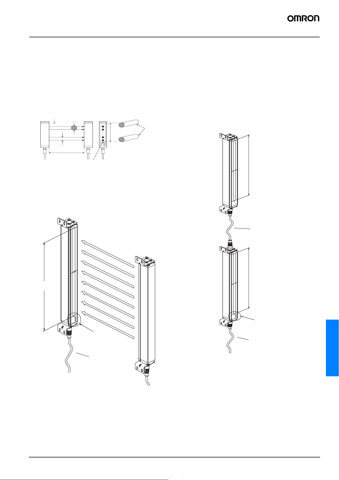
Nomenclature
Protective height
The F3S-B can detect in the area indicated by ”Protective
height” in the figure below. The protective height is from ”the
Optical-axis line mark above the indicator area” to ”the end of
the yellow metal case”.
Optical-axis line mark
The center line for optical axes is indicated by the triangle
mark. This position is a reference line for measuring safety
distance.
No.ofopticalaxes
n-1
Emitter
Detection distance
n
2
1
Optical resolution
Optical- axis
pitch
Receiver
Optical- axis
line mark
Protective
height
Limit position
for detection
Stand-alone type
This is the most common configuration, and it is used to protect a hazardous part of a machine when approached from
one direction only.
Series connection types
When your application requires an additional protective zone,
for example, to prevent someone from staying behind a primary detection zone, the F3S-B may be connected in series.
The system consists of a master unit, a slave unit, and a series connection cable, type F39-JB1B.
The series connection allows up to 96 axes and 2.4 m of protective height in total.
Series connection types have the same characteristics as a
stand-alone types. When the detection zone of the master
unit or that of the slave unit is interrupted, the outputs of the
master unit go to the OFF-state.
Protective
Slave unit
height
Protective
height
Receiver
Indicator area
Extension cable
Emitter
Series connection cable
Protective
Master unit
height
Indicator area
Extension cable
Note: Slave unit does not have indicators.
Master unit and slave unit need to be ordered separately.
F3S-B
G-33F3S-B

Rating and Performance
Type
F3S-B
###
Stand-alone
*1
P
F3S-BM
Master unit for series connection
###P##
*1
###
*1
F3S-BS
Slave unit for series connection
No. of optical axes 12 to 66 6 to 33 4 to 22 12 to 66 6 to 33 4 to 22 12 to 30 6 to 15 4 to10
Optical-axis pitch 25 mm 50 mm 75 mm 25 mm 50 mm 75 mm 25 mm 50 mm 75 mm
Optical resolution
(Detection capability)
Protective height 300 / 450 / 600 / 750 / 900 / 1,050 / 1,200 / 1,350 / 1,500 /
Non-transparent: in diameter
30 mm 55 mm 80 mm 30 mm 55 mm 80 mm 30 mm 55 mm 80 mm
300 / 450 / 600 / 750 mm
1,650 mm
Detection distance 0.3 to 5.0 m, up to 8 m on request
Response time ON to OFF: See table “Response Time”
OFF to ON*2: Default 100 ms (selectable with F39-U1E, 80 to 400 ms)
Startup waiting time 2 s max.
Supply voltage: Vs 24 VDC ± 20% (including 5 Vp-p ripple)
Current
400 mA max. (under no-load conditions)
consumption
Light source Infrared LED (880 nm wavelength). Lifetime: 50,000 hrs. at 25 °C.
Effective aperture angle Within ± 5° for the emitter and receiver at a detection distance of at least 3 m according to IEC
61496-2
Operating mode Light ON
Control output Two PNP transistor outputs, load current 200 mA max., residual voltage 2 V max. (except for volt-
age drop due to cable extension)
Instability output PNP transistor output (not safety-related control output),
activated during an insufficient light detection, failure detection and connection with F39-E1,
load current 100 mA max., residual voltage 2 V max. (except for voltage drop due to cable exten-
sion)
Protection circuit Output short-circuit protection, power supply reverse connection protection
Start/restart
interlock function
Mode selection before power ON by connecting ”Interlock selection input” line to:
Active: No connection or 0 to 2.5 VDC, 3 mA max.
Inactive: Instability output line
Reset of start/restart interlock by connecting ”Interlock selection input” line to:
Interlock reset: 17 VDC to Vs, 20 mA max. Duration time 15 to 2,500 ms
External test function Mode selection by connecting ”External test input” line to:
Active: 17 VDC to Vs, 10 mA max. Duration time at least 15 ms
Inactive: No connection or 0 to 2.5 VDC, 2 mA max.
Relay monitoring
function (optional)
Default inactive, selectable with F39-U1E
Relay monitoring input line with NC contact connected,
Available level: 17 VDC to Vs, 10 mA max.
Allowed relay delay time
*3
: Selectable between 20 and 300 ms
Termination when not selected: No connection or 0 to 2.5 VDC, 2 mA max.
Start interlock function
Default inactive, selectable with F39-U1E
(optional)
Blanking function
Default inactive, selectable with F39-U1E
(optional)
Indicator See ”Indicators” No indicators
Connection method For Extension cable: 8 pins, M12 connector
For Series connection cable: 6 pins, M12 connector
Ambient temperature During operation: –10 to 55 °C (with no freezing)
During storage: –25 to 70 °C
Ambient humidity During operation: 35 to 85 %RH (with no condensation)
During storage: 35 to 95 %RH
Insulation resistance 20 MΩ min. (at 500 VDC)
Dielectric strength voltage 1,000 VAC 50/60 Hz for 1 min
Degree of protection IEC60529 IP65
Vibration resistance Normal operation: 10 to 55 Hz, double-amplitude: 0.7mm, X, Y and Z directions 20 sweeps
2
Shock resistance Normal operation: 100 m/s
[10 G], X, Y and Z directions: 1000 times
Materials Case: Aluminum
Front cover: PMMA (acrylic resin)
End caps: PA6
Size (cross section) 30 x 40 mm
G-34 Safety Sensors / Components
Type
F3S-B
Stand-alone
Accessories Test rod*3, mounting brackets (top and bottom), mounting brackets (intermediate)*4, mounting
plates
*1
###
P
*5
, Instruction manual
F3S-BM
###P##
Master unit for series connection
*5
*1
###
*1
F3S-BS
Slave unit for series connection
Applicable standard IEC(EN)61496-1 TYPE 2 ESPE (Electro-Sensitive Protective Equipment)
IEC 61496-2 TYPE 2 AOPD (Active Opto-electronic Protective Devices)
Note: 1 . For detailed type names and optical specifications, see „Type Naming Rule“
2 .Nominal value (set time). The accuracy is -0 ... +70% of the ON to OFF response time.
3 .Only with F3S-B
4 .For the 1,050 mm protective height and longer types.
5 .Only with F3S-B
###
2P and BM
###P#
###2P##
and BM##2P##.
.
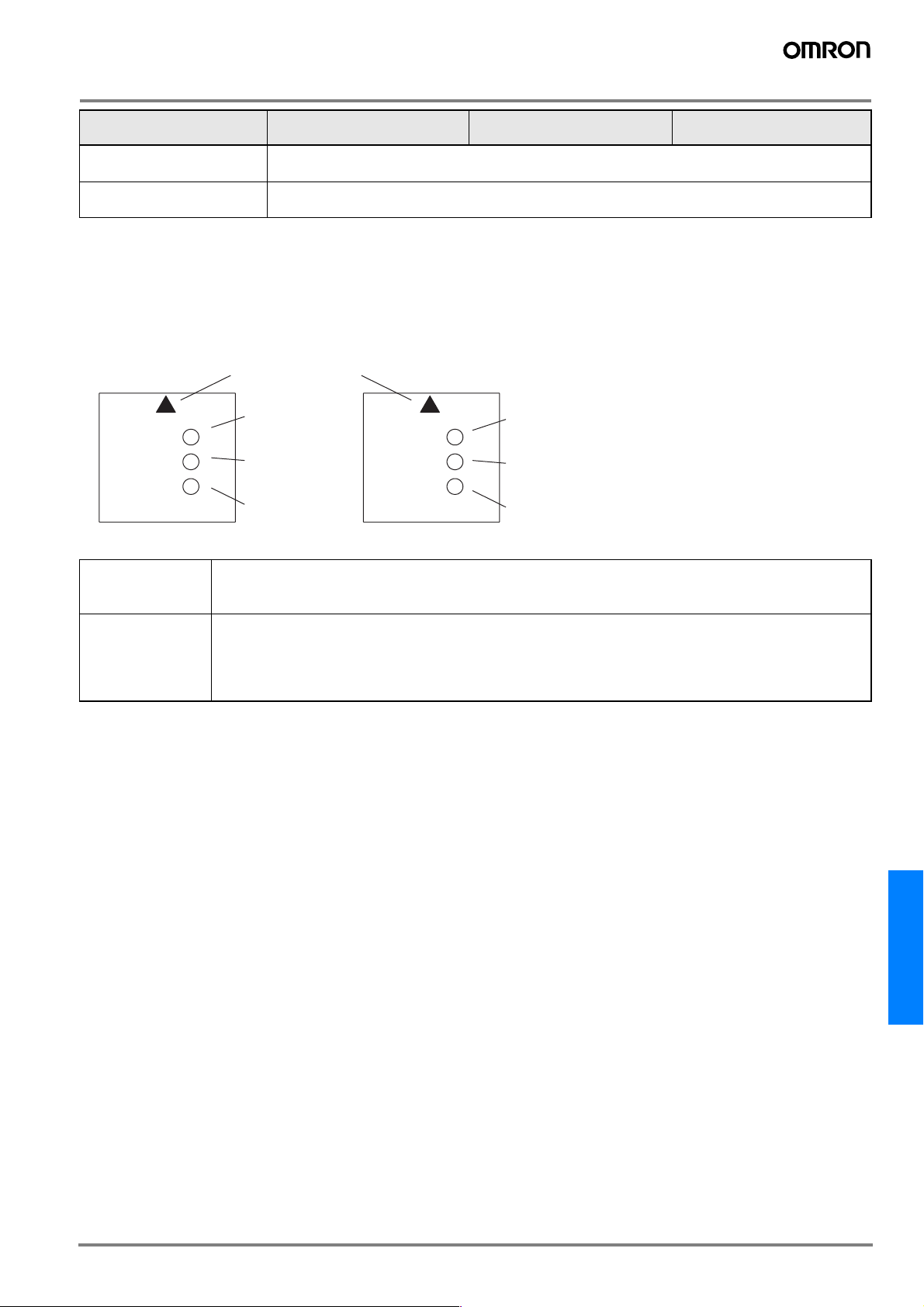
Indicators
<Emitter Indicators>
POWER
INTER-
LOCK
EXT.TEST
BLANKING
Optical- axis
line mark
IR-power indicator
(Orange)
Interlock indicator
(Yellow)
External test /
blanking indicator
(Green)
<Receiver Indicators>
ON
OFF
UNSTAB
ON-state indicator
(Green)
OFF-state indicator
(Red)
Instability indicator
(Orange)
Emitter IR-power indicator: Lit when emitting.
Interlock indicator: Lit during start/restart interlock or start interlock.
External test/ blanking indicator: Lit during external test. / Flashing when using blanking function.
Receiver ON-state indicator: Lit when receiving light.
OFF-state indicator: Lit with interrupted light.
Flashing during connection with F39-E1 or with failure.
Instability indicator: Lit with an insufficient light reception or failure.
Flashing during connection with F39-E1.
F3S-B
G-35F3S-B

Table of Response Time
Stand-alone type
Response time [ms ] Response time [ms ] Response time [ms ]
F3S-B122P 20 F3S-B065P 20 F3S-B047P 20
F3S-B182P 20 F3S-B095P 20 F3S-B067P 20
F3S-B242P 20 F3S-B125P 20 F3S-B087P 20
F3S-B302P 23 F3S-B155P 20 F3S-B107P 20
F3S-B362P 27 F3S-B185P 20 F3S-B127P 20
F3S-B422P 30 F3S-B215P 21 F3S-B147P 20
F3S-B482P 34 F3S-B245P 22 F3S-B167P 20
F3S-B542P 37 F3S-B275P 24 F3S-B187P 20
F3S-B602P 41 F3S-B305P 26 F3S-B207P 20
F3S-B662P 45 F3S-B335P 28 F3S-B227P 21
Series connection types
The following chart shows the response time of combinations of a master unit and a slave unit connected in series. For example,
the response time of the combination of F3S-BM122P30 and F3S-BS302 is 30 ms.
Slave unit F3S-
Master unit
F3S-BM122P
F3S-BM182P
F3S-BM242P
F3S-BM302P
F3S-BM362P
F3S-BM422P
F3S-BM482P
F3S-BM542P
F3S-BM602P
F3S-BM662P
Slave unit F3S-
Master unit
F3S-BM065P
F3S-BM095P
F3S-BM125P
F3S-BM155P
F3S-BM185P
F3S-BM215P
F3S-BM245P
F3S-BM275P
F3S-BM305P
F3S-BM335P
Response time [ms]
BS122 BS182 BS242 BS302
##
20 23 27 30
##
23 27 30 34
##
27 30 34 37
##
30 34 37 41
##
34 37 41 45
##
37 41 45 49
##
41 45 49 54
##
45 49 54 57
##
49 54 57 61
##
54 57 61 65
Response time [ms]
BS065 BS095 BS125 BS155
##
20 20 20 21
##
20 20 21 22
##
20 21 22 24
##
21 22 24 26
##
22 24 26 28
##
24 26 28 30
##
26 28 30 32
##
28 30 32 34
##
30 32 34 35
##
32 34 35 37
Slave unit F3S-
Master unit
F3S-BM047P
F3S-BM067P
F3S-BM087P
F3S-BM107P
F3S-BM127P
F3S-BM147P
F3S-BM167P
F3S-BM187P
F3S-BM207P
F3S-BM227P
Response time [ms]
BS047 BS067 BS087 BS107
##
20 20 20 20
##
20 20 20 20
##
20 20 20 20
##
20 20 20 20
##
20 20 20 21
##
20 20 21 23
##
20 21 23 24
##
21 23 24 25
##
23 24 25 26
##
24 25 26 27
G-36 Safety Sensors / Components
 Loading...