

Page 1

Cat. No. E77E-EN-01
ZX-T Series
F3EM2
Measuring Light Curtain
OPERATION MANUAL
Page 2

Manufacturer: OMRON Europe B.V.
Wegalaan 67-69
2132 JD Hoofddorp, THE NETHERLANDS
WWW www.industrial.omron.eu
User‘s Manual: Version 0.2 dated 18-10-2011
Page 3

Precautions
WARNING
The F3EM2 multi-beam photoelectric sensor with beam evaluation function is not a safety
component for ensuring the safety of people which is defined in EC directive (2006/42/EC) or
by any other regulations or standards.
GENERAL INFORMATION
The instructions in this manual must be followed in order to safeguard correct installation. The
barrier does not contain any parts that are subject to maintenance; do not remove any
electronic parts from the housing for any reason. In case of malfunction, please contact your
sales representative with a description of the failure found and its period of operation. Do not
touch the front protective cover with your hands as dust and/or grease may decrease
performance.
Precautions
OPERATING ENVIRONMENT
Do not use the light curtain in locations with explosive or flammable gas. Make sure that the
product is operated in accordance with IP65 standards. Do not subject the light curtain to
excessive shock when mounting. When using the light curtain in the vicinity of an inverter
motor, be sure to connect the protective earth ground wire of the motor to earth. Failure to
ground the motor may result in malfunction of the light curtain. Further it is recommended to
use shielded cables and to connect the shield to the ground in such cases.
CLEANING
When cleaning the front covers please do not use woollen cloths or organic solvents. The
interval between cleaning depends on conditions in the environment (dust, fog).
POWER SUPPLY VOLTAGE AND OUTPUT LOAD
Do not connect an AC power supply to the Sensor. If AC power (100 VAC or more) is supplied
to the Sensor, it may explode or burn. Make sure that the power supply to the Sensor is within
the rated voltage range. If a voltage exceeding the rated voltage range is supplied to the
Sensor, it may explode or burn.
F3EM2 MEASURING LIGHT CURTAINS OPERATION MANUAL
1
Page 4

Page 5

Table Of Contents
Precautions ........................................................................................... 1
Chapter 1 Overview
1-1 Applications ............................................................................................1-2
1-2 Model line up ..........................................................................................1-3
Chapter 2 Installation
2-1 General...................................................................................................2-2
2-2 Mechanical installation ...........................................................................2-3
2-3 Operating environment ...........................................................................2-4
2-4 Operating distances................................................................................2-4
2-5 Wiring & output circuit.............................................................................2-5
2-6 Setting the internal selector-switches .....................................................2-7
Chapter 3 Operation - General aspects and definitions
3-1 Beam order.............................................................................................3-2
3-2 Output modes .........................................................................................3-3
Chapter 4 Operation - Analog models
4-1 DIP switch setting ...................................................................................4-2
4-2 Analog output value................................................................................4-3
Chapter 5 Operating serial output models (RS-232C)
5-1 DIP switch setting - Overview.................................................................5-2
5-2 Transmission speed (baud rate).............................................................5-4
5-3 Beam aquisition and data aquisition.......................................................5-4
5-4 Communication protocol for serial output ...............................................5-5
Chapter 6 Order codes
Chapter 7 Technical specifications
7-1 Ratings ...................................................................................................7-2
Chapter 8 LED indicators and error indication
8-1 LED indication on receiver unit...............................................................8-2
8-2 LED indication on emitter unit.................................................................8-3
8-3 Troubleshooting for error indication........................................................8-4
Chapter 9 Dimensions
Chapter 10 Accessories
10-1 Mounting bracket ..................................................................................10-2
10-2 Cables ..................................................................................................10-2
Manual Revision History .............................................................................. 1
F3EM2 MEASURING LIGHT CURTAINS OPERATION MANUAL
3
Page 6

4
Page 7

Overview
1-1 Applications ..................................................................1-2
1-2 Model line up.................................................................1-3
1
F3EM2 MEASURING LIGHT CURTAINS OPERATION MANUAL
Page 8
1-1 Applications
1-1 Applications
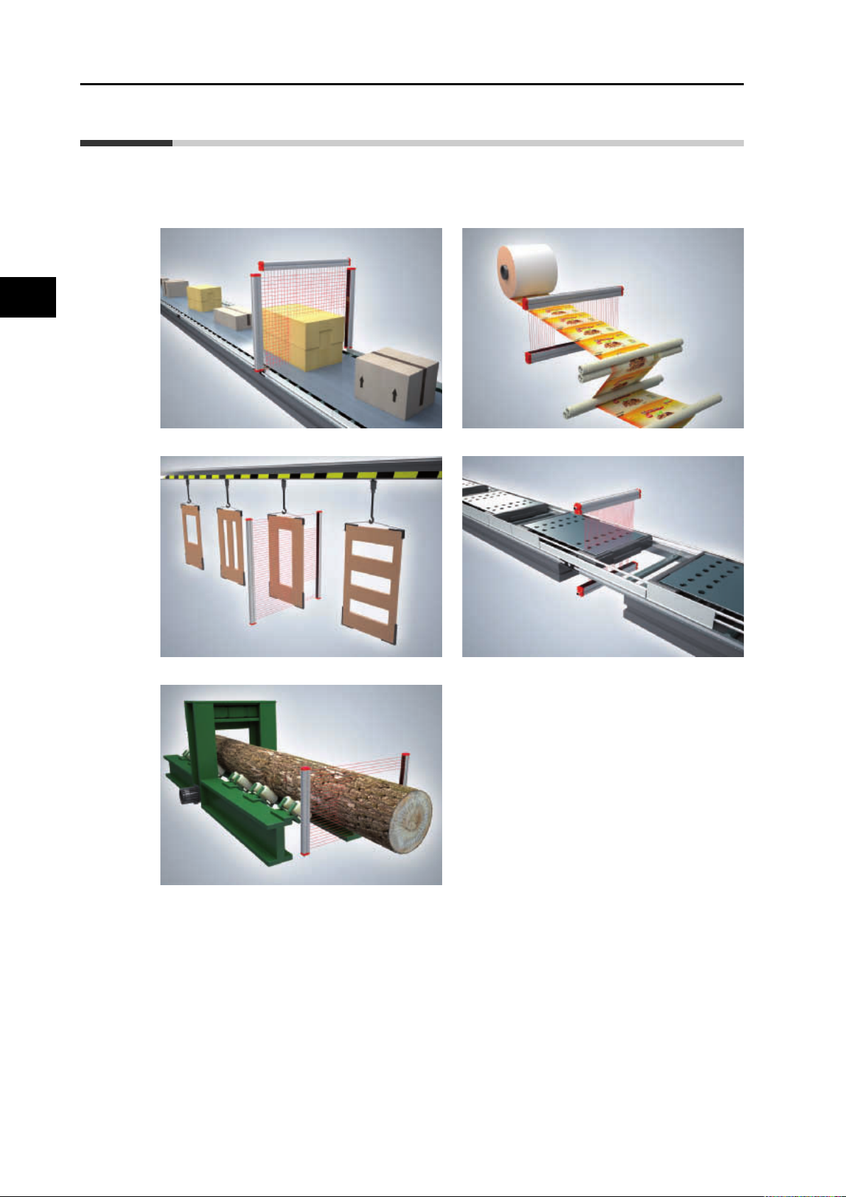
F3EM2 is a multi-beam measuring light curtain designed for easy height and profile
measurement for various applications. Programming via dip switches makes it easy to set up
F3EM2 everywhere without external controller or Remote PC. Due to its robust housing
F3EM2 is also suitable for hash environments in industry.
Overview
Volume measurement Position control
Profile
scan Hole detection
1-2
Wood industry
F3EM2 MEASURING LIGHT CURTAINS OPERATION MANUAL
Page 9

1-2 Model line up
F3EM2 is provided with 3 output versions:
Analogue 0-10 V
RS-232C + analogue 0-10 V
RS485 + analogue 0-10 V (on request)
1-2 Model line up
F3EM2 is available in two resolutions:
Model Sensing distance Pitch resolution Min. detectable object
F3EM2-005-[…] 0 to 3 m 5 mm 10 mm
F3EM2-018-[…] 0 to 15 m 18 mm 30 mm
Models with 7.5mm resolution are available upon request.
Due to its modular design F3EM2 can be provided in various sizes. For standard sizes please
refer to model list in chapter 6.
1
Overview
F3EM2 MEASURING LIGHT CURTAINS OPERATION MANUAL
1-3
Page 10

Page 11

Installation
2-1 General ..........................................................................2-2
2-2 Mechanical installation ................................................2-3
Mounting accessories ..................................................................... 2-3
Additional mounting rigidity ............................................................. 2-3
Mechanical Mounting ...................................................................... 2-4
2-3 Operating environment ................................................2-4
2-4 Operating distances .....................................................2-4
Analogue models ............................................................................ 2-5
Models with serial & analogue output ............................................. 2-6
2-5 Wiring & output circuit .................................................2-5
2-6 Setting the internal selector-switches........................2-7
2
F3EM2 MEASURING LIGHT CURTAINS OPERATION MANUAL
Page 12
2-1 General
X: measuring direction
L: Maximum measurement area
D: System resolution
2-1 General
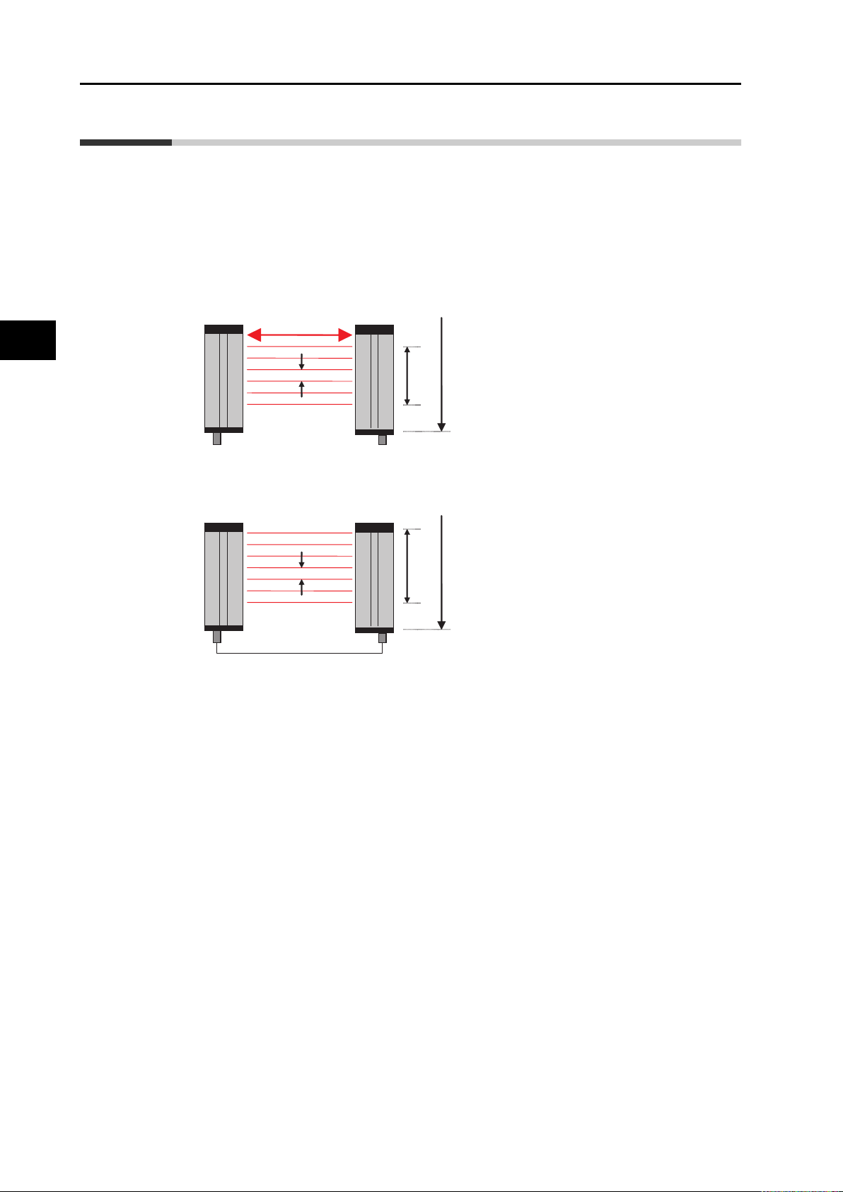
The light curtain consists of one bar with light emitting optical elements and of one with
receiving optical elements. The photosensitive elements are scanned in sequence, thus
broken rays are detected.
F3EM2 features optical synchronisation and does not require synchronization wire between
transmitter and receiver. The sync-function is provided by the upper beam located on the
opposite side of the connector (see illustration below). During operation this beam must always
be kept free. Otherwise it will result a loss of synchronism between the transmitter and
receiver.
Installation
1st BEAM
D
x
X: measuring direction
L
L: Maximum measurement area
D: System resolution
For applications where also the upper beam is needed for measurement synchronization by
wire can be activated (see ’4-1 DIP switch setting’ on page 4-2). In this case transmitter and
receiver must be connected by a sync-wire (see ’2-5 Wiring & output circuit’ on page 2-5).
x
D
L
2-2
F3EM2 MEASURING LIGHT CURTAINS OPERATION MANUAL
Page 13
2-2 Mechanical installation
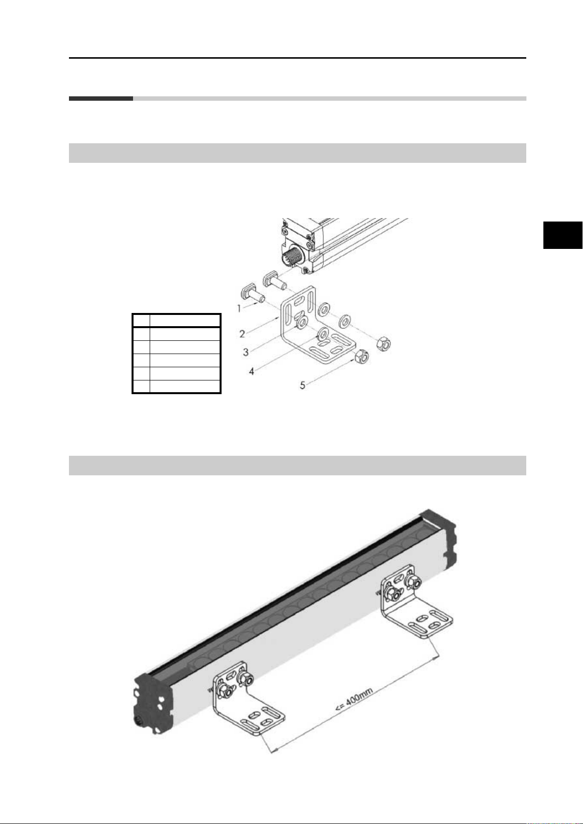
ID Description
1 movable M6 bolt
2 fixing braket
3 M6 washer
4 M6 Grower
5M6 nut
Mounting accessories
The F3EM2 system is mechanically installed by using the T-slots on the two sides or the backside of the housing.
Use the movable bolts, washers, growers and nuts to fix the mounting brackets as shown in
the picture
2-2 Mechanical installation
2
Note: Shipment contains different quantity of brackets, depending on the length of the SLC. Longer SLC
contains a higher number of brackets, following the rule of every 400 mm one bracket.
Additional mounting rigidity
It is recommended that the distance between the mounting brackets is 400 mm or less for
optimum performance of the F3EM2 system.
Installation
F3EM2 MEASURING LIGHT CURTAINS OPERATION MANUAL
2-3
Page 14
2-3 Operating environment
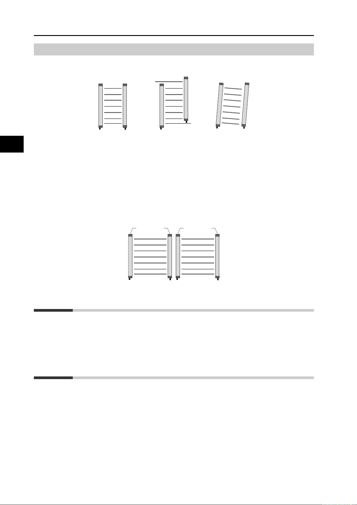
OK NG NG
Mechanical Mounting
Please mount the light curtains in proper alignment as shown in the pictures below by using
the brackets provided with the light curtains.
For serial output models the STROBE input can be used for easier alignment. Please follow
this procedure:
• Turn on the light curtain with the STROBE input connected to +24 VDC
• Move the light curtain to reach the alignment using the led indication on receiver (see led
table 5-1)
• Turn off the light curtain and remove the +24 VDC strobe input connection
Installation
2-3 Operating environment
2-4 Operating distances
If F3EM2 is installed at long distances the laser alignment aid F39-TGR-LLK2-CL provides a
visible laser spot for simplified installation.
If several light curtains are installed close to each other, interference of the light curtains must
be avoided. In this case the assembly should be carried out as follows:
TX TXRXRX
The area for the installation of the light curtain must be suitable according to the technical
specifications. The temperature of the environment, interference caused by electromagnetic
disturbance and ambient light must be considered. Please contact the manufacturer for any
information not contained in this manual.
The operating distances, which are given in the technical specifications, are guaranteed values
for reliable operation. Operating F3EM above the specified sensing distance may cause
greater sensitivity to vibration and possible electro magnetic disturbances.
If the F3EM2 is operated in a distance <1m, the sensitivity can be set to NEAR operation by
dip-switch setting at transmitter (see ’4-1 DIP switch setting’ on page 4-2).
This should be considered for following application conditions:
a) Multiple light curtains are installed close to each other (avoiding mutual interference)
b) Detection of small or semi-transparent objects
If none of above mentioned cases applies, FAR setting should be kept in order to provide
maximum detection reliability.
2-4
F3EM2 MEASURING LIGHT CURTAINS OPERATION MANUAL
Page 15
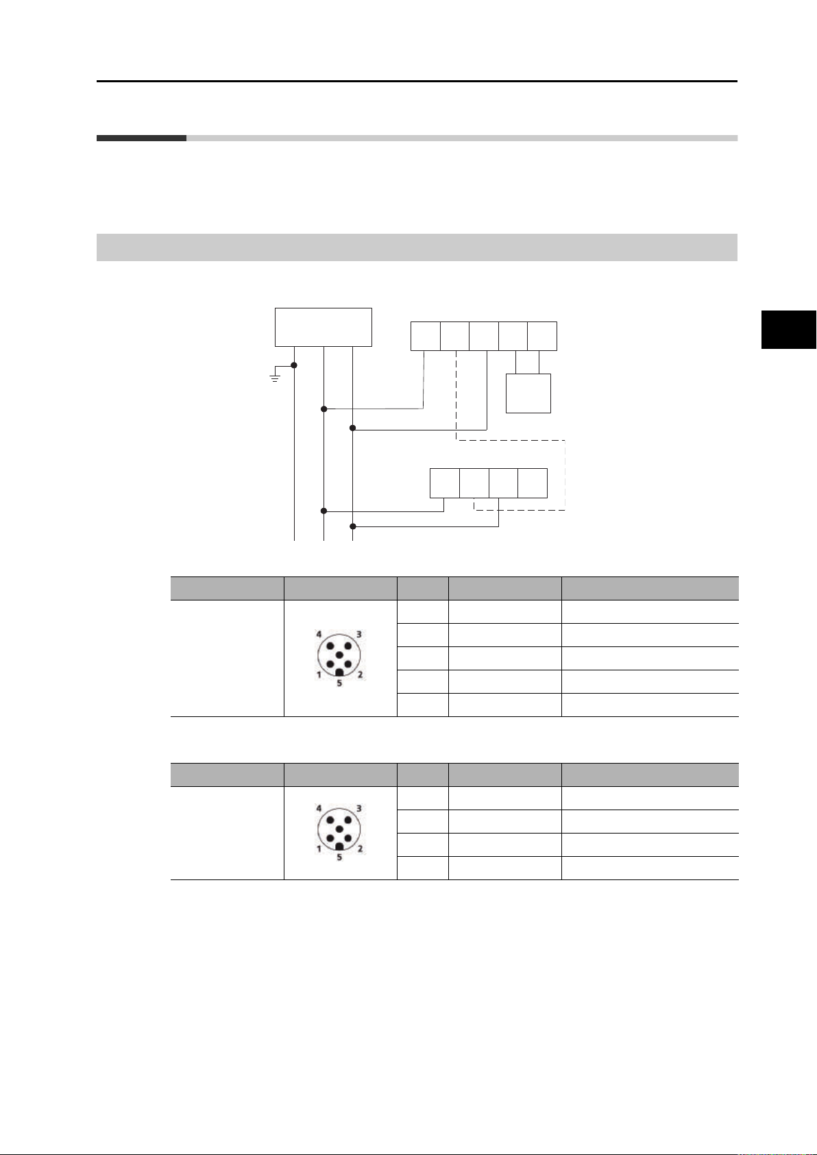
2-5 Wiring & output circuit
The F3EM2 can be operated with analogue output or serial output. Please connect the light
curtain as described below:
Analogue models
2-5 Wiring & output circuit
Connector PIN assignment - Receiver
Type Internal wiring Pin Colour Signal name
M12 n5 pole
Variable
Power Supply
Earth
Ground +24 VDC 0 VDC
RECEIVER F3EM2
analogue out only
Br Wh Bl Bk
EMITTER F3EM2
Br Wh Bl Bk
1Brown +Vs
2 White Wire sync
3Blue 0V
4 Black Analogue +
Gr
Analogue
2
Installation
5 Gray Analogue reference
Connector PIN assignment - Transmitter
Type Internal wiring Pin Colour Signal name
1Brown+Vs
2 White Wire sync
M12 n4 pole
3Blue 0V
4 Black Not used
For synchronization by wire please connect white wires of transmitter and receiver.
F3EM2 MEASURING LIGHT CURTAINS OPERATION MANUAL
2-5
Page 16

2-5 Wiring & output circuit
Safety Points
Models with serial & analogue output
Variable
Power Supply
Earth
Ground +24 VDC 0 VDC
Wh Br Gn Ye Gr Pk Bl Rd
RECEIVER F3EM2
Connector PIN assignment - receiver
Installation
RS out
S
1
EMITTER F3EM2
Br Wh Bl Bk
Analogue
SYNC.
Type Internal wiring Pin Colour Signal name
1
White Strobe input/alignment
(normally open)
2Brown +Vs
3 Green RS+ or RS TX
M12 n8 pole
4 Yellow RS- or RS RX
5 Gray Analogue +
6 Pink Analogue reference
7Blue 0V
8 Red Wire synch
Connector PIN assignment - transmitter
Type Internal wiring Pin Colour Signal name
M12 n4 pole
For synchronization by wire please connect the red wire of receiver with white wire of
transmitter.
We recommend protecting the control unit with an external fuse, whose rated breaking current
must be 1A, even if the appliance is provided with its own internal, self-resetting fuse.
2-6
F3EM2 MEASURING LIGHT CURTAINS OPERATION MANUAL
1Brown +Vs
2 White Wire sync
3Blue 0V
4 Black Not used
Page 17

2-6 Setting the internal selector-switches
Precautions for Correct Use
1 2 3 4 5 6 7 8
OFF
ON
1 2 3 4 5 6 7 8
OFF
ON
2-6 Setting the internal selector-
switches
All the operations listed below must only be carried out when the receiver is disconnected to
the power supply.
Settings like operation mode, baud rate and distance can be changed by selector switches.
To access the selector switches unscrew the end cap of the receiver and transmitter unit:
2
There are two lines of dip switches in each transmitter and receiver. The settings must
be done for both lines. Change the setting of the dip-switch and close the cap again. The light
curtain can now be reconnected to the power supply.
The functions of dip-switches are explained in chapter 4-1 ’DIP switch setting’ on page 4-2.
Installation
F3EM2 MEASURING LIGHT CURTAINS OPERATION MANUAL
2-7
Page 18

Page 19

Operation - General aspects and definitions
F3EM2 is not a safety device. The usage of F3EM2 as Safety protection
equipment is dangerous and prohibited and expose personnel to serious injury.
3-1 Beam order....................................................................3-2
3-2 Output modes ...............................................................3-3
3
F3EM2 MEASURING LIGHT CURTAINS OPERATION MANUAL
Page 20

3-1 Beam order
Safety Points
F3EM2 is not a safety device. The usage of F3EM2 as Safety protection equipment is
dangerous and prohibited and expose personnel to serious injury.
The light curtain consists of an array of beams that can be obscured by an object between
transmitter and receiver. The status of each beam (open or blocked) is controlled every scan
cycle and the output reflects the current status accordingly. Thus size and position of objects
can be detected.
Different output modes are available to adapt F3EM2 operation to the given application and to
simplify installation into the machine.
3-1 Beam order
Beams are numbered in the way as shown in the picture; starting from beam 1
opposite to connector to the last beam at the connector side of the light curtain.
Operation - General aspects and
Beam status in the protocol is defined as follows:
Beam open = 0
Beam blocked = 1
3-2
F3EM2 MEASURING LIGHT CURTAINS OPERATION MANUAL
Page 21

3-2 Output modes
The F3EM2 light curtain can provide various output modes and combination of these to
describe the position and the size of an object:
FBB (First Beam Blocked) First beam in chain obscured by object
FBM (First Beam Made) First beam in chain that is open
NBB (Number of Beams Blocked) Total number of blocked beams - no holes included
NAB (Number of Area Blocked) Number of beams from 1st blocked to last blocked beam
(including holes)
LBB (Last Beam Blocked) Last blocked beam in the chain
LBM (Last Beam Made) Last open beam in the chain
Bitmap The status of each beam (serial models)
Example:
FBM
FBB
1
3-2 Output modes
3
Operation - General aspects and defi-
LBB
LBM
9
In serial operation F3EM2 can transmit status of each single beam or a combination of two
output values. See 3 examples how this is reflected for each function:
Examples:
1
9
Case A Case B Case C
Case A Case B Case C
Function Output values Output values Output values
Bitmap
FBB + NBB 4 and 4 7 and 3 2 and 3
FBM + NAB 1 and 4 1 and 3 1 and 7
F3EM2 provides the status of
each single beam
1
9
F3EM2 provides the status of
each single beam
1
9
F3EM2 provides the status of
each single beam
LBB + NBB 7 and 4 9 and 3 8 and 3
LBM + NAB 9 and 4 6 and 3 9 and 7
Specification and settings of each function and the serial protocol configuration are described
in chapter 5 ’Operating serial output models (RS-232C)’ on page 5-1.
F3EM2 MEASURING LIGHT CURTAINS OPERATION MANUAL
3-3
Page 22

Page 23

Operation - Analog models
4-1 DIP switch setting.........................................................4-2
4-2 Analog output value .....................................................4-3
4
F3EM2 MEASURING LIGHT CURTAINS OPERATION MANUAL
Page 24

4-1 DIP switch setting
4-1 DIP switch setting
Transmitter:
Dip-SW Status Function
Receiver:
1
2 Not used
OFF OFF NAB (default)
3 + 4
5
6 Not used
7 Not used
8 Not used
Dip-SW Status Function
1
2
OFF ON LBB
ON OFF NBB
ON ON FBB
OFF OFF NAB (default)
OFF Optical Sync (default)
ON Wire sync
3 4 Output signal
OFF FAR (default)
ON NEAR
OFF Optical Synch (default)
ON Wire synch
OFF 0 to 10V (default)
ON 10 to 0V
3 4 Output signal
Operation - Analog models
3 + 4
5 Not USED
6 Not USED
7 Not USED
8 Not USED
There are two lines of dip switches in each transmitter and receiver. The settings must
be done for both lines.
4-2
F3EM2 MEASURING LIGHT CURTAINS OPERATION MANUAL
OFF ON LBB
ON OFF NBB
ON ON FBB
Page 25

4-2 Analog output value
Output voltage
(total No° of beams blocked) 10
Total numbers of beams
---------------------------------------------------------------------------------------- V D C=
Output voltage
(index No° of first beam blocked) 10
Total numbers of beams
----------------------------------------------------------------------------------------------------VDC=
The output value has linear relationship to the number of interrupted beams (NBB or NBM
setting) or to the position index of beam (FBB or LBB).
Example for NAB setting:
Example for FBB setting:
The analogue output is refreshed every scanning cycle.
4-2 Analog output value
4
Operation - Analog models
F3EM2 MEASURING LIGHT CURTAINS OPERATION MANUAL
4-3
Page 26

Page 27

Operating serial output models (RS-232C)
5-1 DIP switch setting - Overview......................................5-2
5-2 Transmission speed (baud rate) .................................5-4
5-3 Beam aquisition and data aquisition ..........................5-4
5-4 Communication protocol for serial output.................5-5
Bitmap of optics .............................................................................. 5-5
FBB + NBB ..................................................................................... 5-6
FBM + NAB..................................................................................... 5-6
LBB + NBB...................................................................................... 5-7
LBM + NBM .................................................................................... 5-7
Continues bitmap transmission ....................................................... 5-7
Bitmap + Analogue out (FBB) ......................................................... 5-8
Holes detection function.................................................................. 5-8
5
F3EM2 MEASURING LIGHT CURTAINS OPERATION MANUAL
Page 28

5-1 DIP switch setting - Overview
The RS-232C serial interface of F3EM is specified as follows:
• Full duplex operation
• Data format: 8-N-1 (bit start - 8-bit data - 1-bit stop - no parity)
• The signal on analogue output is calculated as shown in chapter 4-2 ’Analog output value’
on page 4-3
5-1 DIP switch setting - Overview
Dip switch setting transmitter:
Dip-SW Status Function
Operating serial output models
1
2+3
4 Not used
5
OFF OFF OFF Bitmap of optics (default) NAB (default)
OFF OFF ON FBB + NBB (4 byte total) NAB
OFF ON OFF FBM + NAB (4 byte total) LBB
6+7+8
OFF ON ON LBB + NBB (4 byte total) NBB
ON OFF OFF LBM + NAB (4 byte total) FBB
ON OFF ON
ON ON OFF FBB + LBB (4 byte total) NBB
ON ON ON Holes detection disabled
OFF Optical Synch (default)
ON Wire synch
RS baud rate
2 3 Speed
OFF OFF 9600bps (default)
OFF ON 19200bps
ON OFF 38400bps
ON ON 76800bps
OFF FAR (default)
ON NEAR
Output function
6 7 8 Serial output Analogue output
Continuous bitmap
transmission
disabled
5-2
F3EM2 MEASURING LIGHT CURTAINS OPERATION MANUAL
Page 29

5-1 DIP switch setting - Overview
Dip-switch setting receiver:
Dip-SW Status Function
1
OFF Optical Synch (default)
ON Wire synch
RS baud rate for serial operation
2 3 Speed
2+3
4+5
6+7+8
OFF OFF 9600bps (default)
OFF ON 19200bps
ON OFF 38400bps
ON ON 76800bps
Interrogation byte for serial operation
4 5
OFF OFF
OFF ON FBh / 11111011 0-10V
ON OFF FCh / 11111100 10-0V
ON ON FDh /11111101 10-0V
6 7 8 Serial output Analogue output
OFF OFF OFF Bitmap of optics (default) NAB (default)
OFF OFF ON FBB + NBB (4 byte total) NAB
OFF ON OFF FBM + NAB (4 byte total) LBB
OFF ON ON LBB + NBB (4 byte total) NBB
Hexadecimal code /
binary code
FAh
11111010 (default)
Output function
Analogue output
0-10V (default)
5
Operating serial output models (RS-
ON OFF OFF LBM + NAB (4 byte total) FBB
ON OFF ON
ON ON OFF FBB + LBB (4 byte total) NBB
ON ON ON Holes detection disabled
Continuous bitmap
transmission
disabled
There are two lines of dip switches in each transmitter and receiver. The settings must
be done for both lines.
F3EM2 MEASURING LIGHT CURTAINS OPERATION MANUAL
5-3
Page 30

5-2 Transmission speed (baud rate)
Precautions for Correct Use
5-2 Transmission speed (baud rate)
The baud rate can be set by DIP switch 2 and 3.
RS baud rate
2 3 Speed
OFF OFF 9600bps (default)
OFF ON 19200bps
ON OFF 38400bps
ON ON 76800bps
The baud rate must be set both on the receiver bar dip-switches as well as the transmitter bar
dip-switches to align the timing synchronism of the two bars.
5-3 Beam aquisition and data aquisition
In order to understand the functions of F3EM2 and to choose the right operation mode it is
important to differentiate:
Beam acquisition = Conditions of beams checked at one scanning cycle of the light curtain.
Data acquisition = Sum of beam acquisitions gathered in the time frame between 2 external
interrogations.
The light curtain saves the beam acquisition made at each scanning cycle and executes a
logical "OR" between the status of new acquired beams and the previous one.
See an example of a data acquisition resulting from two beam acquisitions:
Operating serial output models
Triggered by an interrogation code the light curtain sends the acquired data and cleans the
beam status memory again.
1 0 0 0 0 1
1 0 0 1 0 0 1 0 1
1 0 0 1 0 1 1 0 1
1 0 0
Previous beam acq.
Last beam acq.
Data ready to be sent
In practice this process enables for example the measuring of the maximum height of an
irregular shaped object that is moving through the light curtain. Thus only the relevant
information is transmitted.
Because the beams are scanned sequentially it can occur that a command or trigger arrives
before the scan is completed. In this case the scan is interrupted and the status of the scan
before is transferred in the response protocol.
Note:F3EM2 also provides continuous bitmap transmission. In this mode the light curtain continuously
sends each beam acquisition to the host / PLC. In this case however the host has to process a much
higher amount of data.
5-4
F3EM2 MEASURING LIGHT CURTAINS OPERATION MANUAL
Page 31
5-4 Communication protocol for serial output
Number of bytes INT number of optical units 7+8=
5-4 Communication protocol for serial
output
The communication of the serial interface provides various possible operation modes
depending the dip-switch setting. All of them respect the following timeline:
Host sends interrogation code
F3EM2 reply with acquired data & cleans the data memory.
F3EM2 starts again with data acquisition & waits for next interrogation code
The interrogation codes can be set by dip switches 4+5 (see chapter 5-1 on page 5-2).
Note:After power-on F3EM2 starts automatically with data acquisition (without interrogation code).
The communication can also be forced by signal on the STROBE input (PNP logic); the light
curtain responds on the serial line with the desired data.
Note: This STROBE line can be used also as a check for the correctness of the serial wiring and/or
communication protocol.
The different operation modes are described below.
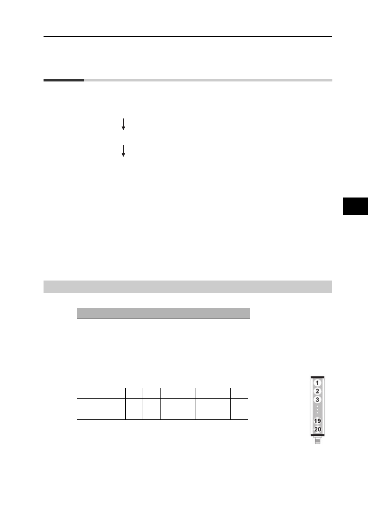
Bitmap of optics
Dip switch setting:
6 7 8 Type of function
OFF OFF OFF Bitmap of optics (default)
The light curtain responds with a serial of bytes. The quantity of bytes depends on the total
number of beams.
Each beam status is reflected by one bit. The beam index numbers are addressed to bits as
shown in the example below. Remaining unused bits in the last byte are set to zero.
E.g. the response of a light curtain with 20 beams is 3 bytes.
The numbers in the table reflect the beam index No:
st
byte12345678
1
nd
byte 9 10111213141516
2
rd
byte 17 18 19 20 0 0 0 0
3
5
Operating serial output models (RS-
The beam with index 1 starts opposite from the connector.
As a result each response byte contains 8 beams. The following formula applies
for the calculation if the number of response bytes:
The maximum number of optical beams that can be managed by serial interface is 400.
F3EM2 MEASURING LIGHT CURTAINS OPERATION MANUAL
5-5
Page 32

5-4 Communication protocol for serial output
Bit signal vs. beam status is:
0 = BEAM NOT INTERUPTED
1 = BEAM INTERRUPTED
FBB + NBB
Dip switch setting:
6 7 8 Type of function
OFF OFF ON FBB + NBB
The reply received from the light curtain is composed of 4 bytes.
The first two bytes are related to FBB data
The second two bytes are related to NBB.
FBB data is the binary conversion of the FBB id number.
NBB data is the binary conversion of the NBB number.
Example of the response protocol of a light curtain with 9 beams and FBB + NBB settings:
FBB
NBB
Operating serial output models
FBM + NAB
Dip switch setting:
1
9
st
1
byte H
FBB
nd
2
FBB
rd
byte H
3
NBB
th
byte L
4
NBB
byte L
00000000
00000100
00000000
00000100
H = high order byte
L = low order byte
6 7 8 Type of function
OFF ON OFF FBM + NAB
FBB = 4, NBB = 4 (HEX FORMAT)
5-6
The reply received from the light curtain is composed of 4 bytes.
The first two bytes are related to FBM data
The second two bytes are related to NAB.
FBM data is the binary conversion of the FBM id number.
NAB data is the binary conversion of the NAB number.
The order of bytes in the protocol is same as example described for FBB + NBB setting.
F3EM2 MEASURING LIGHT CURTAINS OPERATION MANUAL
Page 33

LBB + NBB
Dip switch setting:
OFF ON ON LBB + NBB
The reply received from the light curtain is composed of 4 bytes.
The first two bytes are related to LBB data
The second two bytes are related to NBB.
LBB data is the binary conversion of the LBB id number.
NBB data is the binary conversion of the NBB number.
The order of bytes in the protocol is same as example described for FBB + NBB setting.
LBM + NBM
5-4 Communication protocol for serial output
6 7 8 Type of function
Dip switch setting:
6 7 8 Type of function
ON OFF OFF LBM + NAB
The reply received from the light curtain is composed of 4 bytes.
The first two bytes are related to LBM data
The second two bytes are related to NAB.
LBM data is the binary conversion of the LBM id number.
NAB data is the binary conversion of the NAB number.
The order of bytes in the protocol is same as example described for FBB + NBB setting.
Continues bitmap transmission
Dip switch setting:
6 7 8 Type of function
ON ON OFF Bitmap + Analogue out (FBB)
This setting allows the light curtain to transmit the bitmap of optics every cycle time.
5
Operating serial output models (RS-
The interrogation code is used as a start and stop trigger.
After power-on the LC waits for the interrogation code to start transmitting.
When interrogation code was received the LC continuously sends out the updated bitmap of
optics every cycle time. When the light curtain receives a further interrogation code it stops
transmitting and waits for the next interrogation code to start again the transmission.
The order of bitmaps is described in ’Bitmap of optics’ on page 5-5.
F3EM2 MEASURING LIGHT CURTAINS OPERATION MANUAL
5-7
Page 34

5-4 Communication protocol for serial output
Bitmap + Analogue out (FBB)
Dip switch setting:
6 7 8 Type of function
ON OFF ON
In this set-up the light curtain drives together the Serial and the analogue output.
Note:The analogue output reflects the status of the FBB and is constantly updated. The serial output, on
the contrary, transmit its data only after interrogation code receipt.
The order of bitmaps is described in ’Bitmap of optics’ on page 5-5.
Holes detection function
Dip switch setting:
6 7 8 Type of function
ON ON ON Holes detection
This function transmits the bitmap of beams with inverted bit signals.
The default setting
"0 = beam free and 1 = beam broken"
is converted into
"0 = beam occupied and 1= beam free".
Continuous bitmap
transmission
Thus without object the bitmap of all optics will show "1", if the light curtain is aligned correctly.
Acquired data reflects the sum of beam acquisitions and is sent on interrogation code as
described in 5-3 ’Beam aquisition and data aquisition’ on page 5-4.
The order of bitmaps is described in ’Bitmap of optics’ on page 5-5.
Operating serial output models
5-8
F3EM2 MEASURING LIGHT CURTAINS OPERATION MANUAL
Page 35

Order codes
6
F3EM2 MEASURING LIGHT CURTAINS OPERATION MANUAL
Page 36

Order code
RS232C Serial/
analogue output
models
F3EM2-005-150 F3EM2-005-150-AV
F3EM2-018-150 F3EM2-018-150-AV 18 mm 15 m 8
F3EM2-005-300 F3EM2-005-300-AV
F3EM2-018-300 F3EM2-018-300-AV 18 mm 15 m 16
*2
Analogue models
Measurement
range
150
300
Pitch
5mm 3 m 30
5mm 3 m 60
*1
Sensing
distance
Channels
F3EM2-005-450 F3EM2-005-450-AV
450
F3EM2-018-450 F3EM2-018-450-AV 18 mm 15 m 24
F3EM2-005-600 F3EM2-005-600-AV
600
F3EM2-018-600 F3EM2-018-600-AV 18 mm 15 m 32
F3EM2-005-900 F3EM2-005-900-AV
900
F3EM2-018-900 F3EM2-018-900-AV 18 mm 15 m 48
F3EM2-005-1200 F3EM2-005-1200-AV
1200
F3EM2-018-1200 F3EM2-018-1200-AV 18 mm 15 m 64
F3EM2-005-1500 F3EM2-005-1500-AV
1500
F3EM2-018-1500 F3EM2-018-1500-AV 18 mm 15 m 80
F3EM2-005-1800 F3EM2-005-1800-AV
1800
F3EM2-018-1800 F3EM2-018-1800-AV 18 mm 15 m 96
F3EM2-018-2100 F3EM2-018-2100-AV 2100 18 mm 15 m 112
*1. Models with 7.5 mm pitch are available. Contact your OMRON representative.
*2. Models with RS485 serial output are available. Contact your OMRON representative.
5mm 3 m 90
5mm 3 m 120
5mm 3 m 180
5mm 3 m 240
5mm 3 m 300
5mm 3 m 360
Order codes
6-2
F3EM2 MEASURING LIGHT CURTAINS OPERATION MANUAL
Page 37

Technical specifications
7-1 Ratings...........................................................................7-2
7
F3EM2 MEASURING LIGHT CURTAINS OPERATION MANUAL
Page 38

7-1 Ratings
7-1 Ratings
Models F3EM2-005-… F3EM2-018-…
Operating distance 3 m 15 m
Light source (wave length) Infrared (880 nm)
Pitch 5.3 mm 18.3 mm
Max. number of beams 400 max on serial output
Operation temperature –10° to +55°C
Storage temperature –10° to +75°C
Degree of protection IP65 (IEC 60529)
Operating voltage 24 VDC ±20%
Current consumption 150 mA max (excluded load on digital)
Power-on delay <1 s
Response time 4 ms + 80 µs x number of beams (+ transmitting time for serial
operation*1)
Outputs RS-232C / RS485 / Analogue 0-10 V (12 bits)
External input Strobe input
Protective circuits Reverse polarity protection, output short-circuit protection
Max. load on analog output 15 mA
Insulation resistance >20 M
Dielectric voltage strength 350 VAC (1 min)
Configuration By dip-switches
Operating modes Analogue output 0-10 V or 10-0 V
Housing material Aluminum
Front Window Material Acrylic Lexan
End Cap and Connector ABS
Sealing Gasket Material EPDM
*1) Serial transmission time = 1/bps x 10 x number of transmitted byte
Technical specifications
Serial output: RS-232C (RS485 on request)
7-2
F3EM2 MEASURING LIGHT CURTAINS OPERATION MANUAL
Page 39

LED indicators and error indication
8-1 LED indication on receiver unit...................................8-2
8-2 LED indication on emitter unit.....................................8-3
8-3 Troubleshooting for error indication ..........................8-4
8
F3EM2 MEASURING LIGHT CURTAINS OPERATION MANUAL
Page 40

8-1 LED indication on receiver unit
POWER
RUN
FREE
BREAK
STATUS
RX
Meaning of symbols
SYMBOL MEANING
Diagnosis LED off
Diagnosis LED on
Diagnosis LED blinking
8-1 LED indication on receiver unit
Status of Receiver is displayed by 5 LEDs:
Disposition of indicator Name of indicator Colour
POWER Green
RUN Yellow
FREE Green
BREAK Red
STATUS Yellow
Normal operation indication on receiver:
LED signal pattern Description
No object in field. Running ok
Object in field. Running ok
Correct alignment reached
LED error indication on receiver:
ID LED signal pattern Description
1
2
3
4
LED indicators and error indication
Low supply voltage
Error on microcontroller
Error on optical system
Wrong dip switch configuration
8-2
F3EM2 MEASURING LIGHT CURTAINS OPERATION MANUAL
Page 41

8-2 LED indication on emitter unit
POWER
STATUS 1
RANGE
STATUS 2
TX
8-2 LED indication on emitter unit
Status of Emitter is displayed by 4 LEDs:
Disposition of indicator Name of indicator Colour
POWER Green
STATUS 1 Yellow
RANGE Green
Not used Red
STATUS 2 Yellow
Normal operation indication on emitter:
LED signal pattern Description
Emitter working, short range selected.
Emitter working, long range selected.
LED error indication on emitter:
ID LED signal pattern Description
1
2
3
4
Low supply voltage
Error on microcontroller
Error on optical system
Wrong dip switch configuration
8
LED indicators and error indication
F3EM2 MEASURING LIGHT CURTAINS OPERATION MANUAL
8-3
Page 42

8-3 Troubleshooting for error indication
ID Actions
1 Check if power supply is within specification of 24Vdc ± 20%
2 Turn the unit ON and OFF again. If the error persist, please contact manufacturer
3 Turn the unit ON and OFF again. If the error persist, please contact manufacturer
4 Check the setting of switches
Page 43

Dimensions
9
F3EM2 MEASURING LIGHT CURTAINS OPERATION MANUAL
Page 44
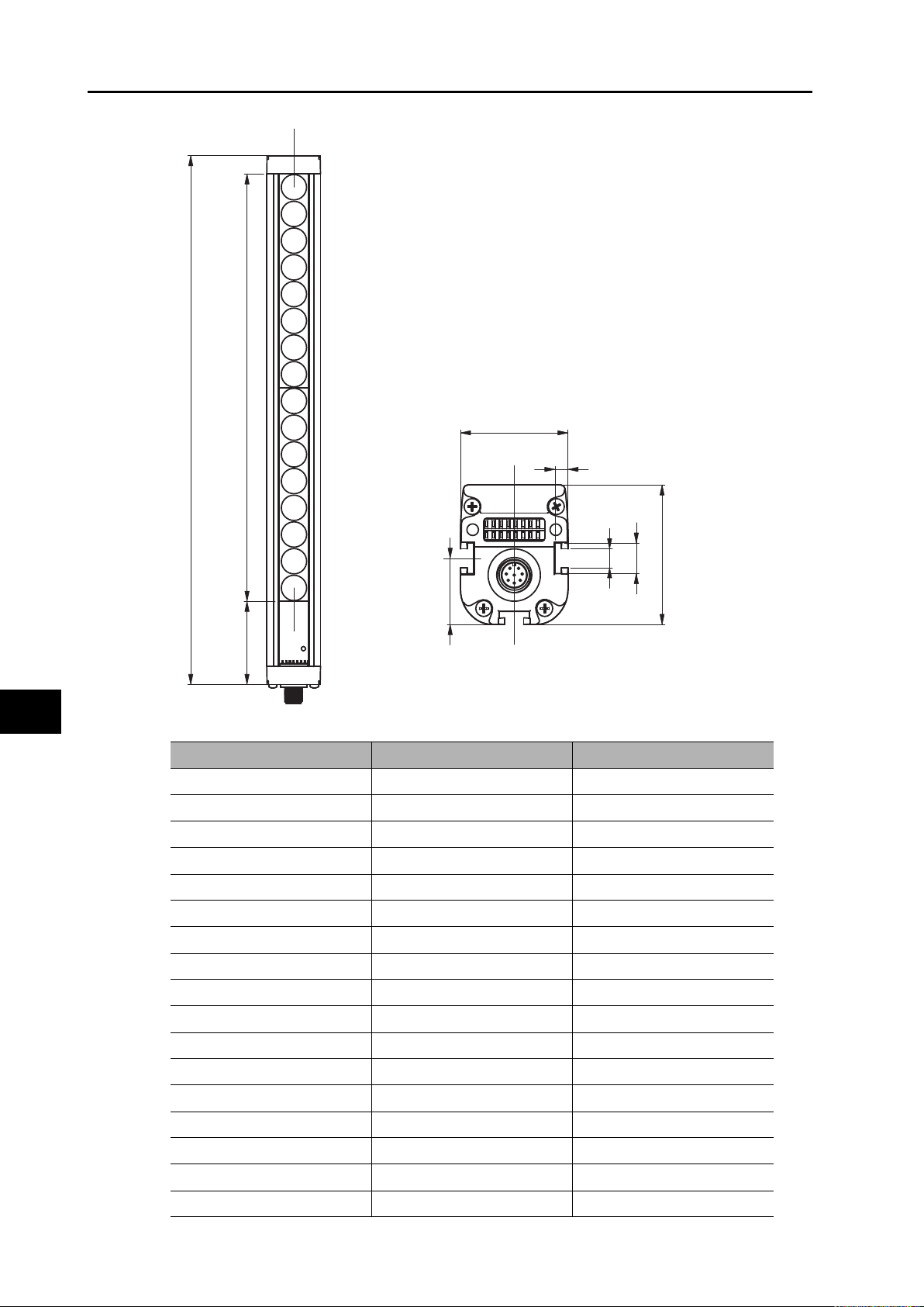
L: Total length
E: Detection zone
A: Dead zone without detection capability
E
Dimensions
L
22.75
A
37
4.5
6.5
All dimensions shown are in mm
Item number Detection Zone E (mm) Total length L (mm)
F3EM2-005-150(-AV) 159 218
F3EM2-018-150(-AV) 147 217
F3EM2-005-300(-AV) 318 277
F3EM2-018-300(-AV) 294 364
F3EM2-005-450(-AV) 477 536
F3EM2-018-450(-AV) 441 511
F3EM2-005-600(-AV) 636 695
F3EM2-018-600(-AV) 588 658
10.5
48
9-2
F3EM2-005-900(-AV) 954 1013
F3EM2-018-900(-AV) 882 952
F3EM2-005-1200(-AV) 1272 1331
F3EM2-018-1200(-AV) 1176 1246
F3EM2-005-1500(-AV) 1590 1649
F3EM2-018-1500(-AV) 1470 1540
F3EM2-005-1800(-AV) 1908 1967
F3EM2-018-1800(-AV) 1764 1834
F3EM2-018-2100(-AV) 2058 2128
F3EM2 MEASURING LIGHT CURTAINS OPERATION MANUAL
Page 45

Accessories
10-1 Mounting bracket........................................................10-2
10-2 Cables..........................................................................10-2
10
F3EM2 MEASURING LIGHT CURTAINS OPERATION MANUAL
Page 46
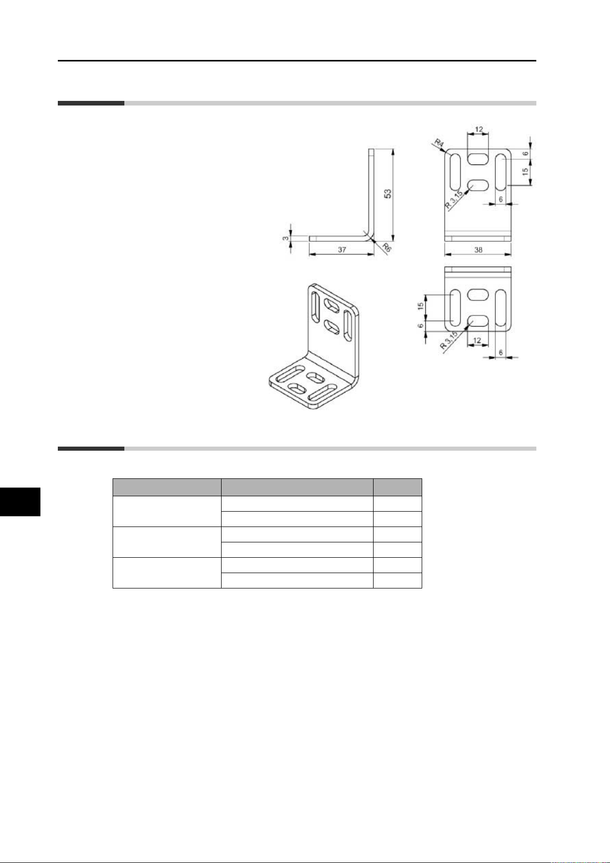
10-1 Mounting bracket
10-1 Mounting bracket
(provided with the product)
10-2 Cables
Accessories
Order Code Length
M12-8pin
(straight, shielded)
M12-5pin
(straight)
M12-5pin
(angled)
For other accessories like alignment kit, special brackets or connector cables please contact
your sales representative.
Y92E-M12PURSH8S2M-L 2 m
Y92E-M12PURSH8S5M-L 5 m
XS2F-M12PVC5S2M 2 m
XS2F-M12PVC5S5M 5 m
XS2F-M12PVC5A2M 2 m
XS2F-M12PVC5A5M 5 m
10-2
F3EM2 MEASURING LIGHT CURTAINS OPERATION MANUAL
Page 47

Manual Revision History
The manual revision symbol is an alphabet appended at the end of the manual number found
in the bottom left-hand corner of the front or back cover.
Example
E77E-EN-01
Revision symbol
Revision
symbol
01 January 2012 First Print.
Revision date Description of revision and revised page
F3EM2 MEASURING LIGHT CURTAINS OPERATION MANUAL
1
 Loading...