

Page 1
Measuring lightcurtain in robust aluminium housing
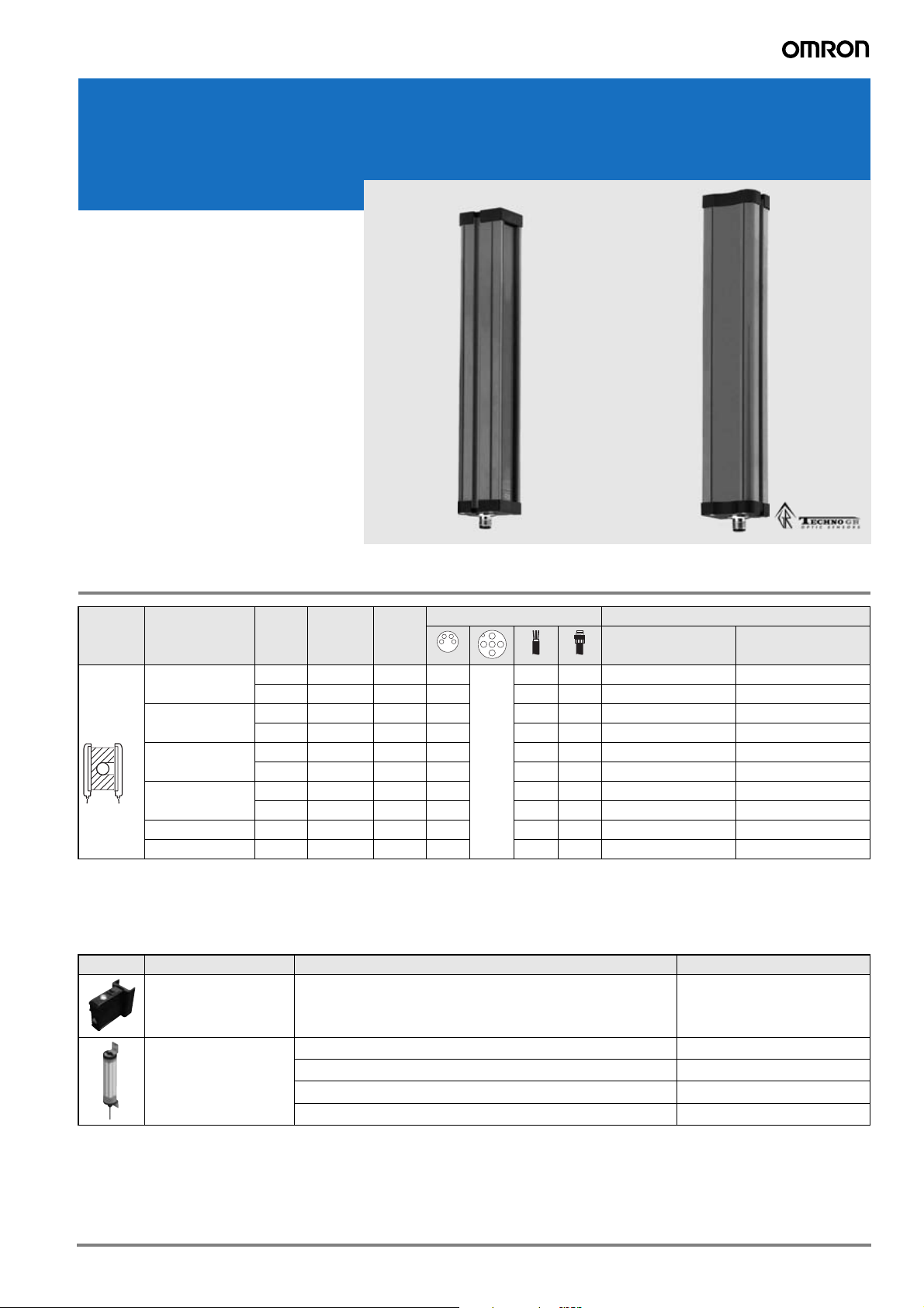
F3EM
Measuring lightcurtain
in robust aluminium
housing
The F3EM provides easy to install and set
up height and profile measurement. The
analog output provides a simple overall
height detection and the serial output models provide single beam evaluation for profile measurements.
• Robust aluminium housing
• Analog output for simple height detections
• Serial output with single beam evaluation
for profile measurement
Ordering Information
Sensor
type
Throughbeam
(measuring)
1
Models with 7.5 mm pitch are available. Contact your OMRON representative.
2
Models with RS485 serial output are available. Contact your OMRON representative.
Measurement
range (MaxM)
150 5 mm 3 m 30 – 5 pin – – F3EM-005-150-AV F3EM-005-150-D2
300 5 mm 3 m 60 – – – F3EM-005-300-AV F3EM-005-300-D2
600 5 mm 3 m 120 – – – F3EM-005-600-AV F3EM-005-600-D2
900 5 mm 3 m 180 – – – F3EM-005-900-AV F3EM-005-900-D2
2000 5 mm 3 m 400 – – – – F3EM-005-2000-D2
2100 18 mm 15 m 112 – – – F3EM-018-2100-AV F3EM-018-2100-D2
Pitch
18 mm 15 m 8 – – – F3EM-018-150-AV F3EM-018-150-D2
18 mm 15 m 16 – – – F3EM-018-300-AV F3EM-018-300-D2
18 mm 15 m 32 – – – F3EM-018-600-AV F3EM-018-600-D2
18 mm 15 m 48 – – – F3EM-018-900-AV F3EM-018-900-D2
distance
Sensing
1
Channels
Lightcurtain accessories
Shape Type Comment Order Code
Laser alignment kit snap-on Laser beam generator and level F39-TGR-LLK2-SB
Connection method Order code
Analog output RS232 output
2
Protective tube for F3ET-_ -150 F3ET-IP150
for F3ET-_ -300 F3ET-IP300
for F3ET-_ -600 F3ET-IP600
for F3ET-_ -900 F3ET-IP900
1F3EM Measuring lightcurtain in robust aluminium housing
Page 2
Rating/Specifications
Item
Through-beam
F3EM-005_ F3EM-018_
Sensing distance 0 to 3 m 0 to 15 m
Vertical measurement range 0 to MaxM mm; MaxM: 150, 300, 600, 900,
2000
1
0 to MaxM mm; MaxM: 150, 300, 600, 900,
2
2100
Minimum detectable object size 10 mm 30 mm
Pitch 5 mm 18 mm
Control
output
Analog models 0-10 VDC, max. load current 30 mA
Serial models RS 232
Response time Analog output: 5 ms + 0,18 x channels; Serial output: 4.5 ms + 0.38 x channels at 4800 bps
Light source (wave length) Infrared LED (950 nm)
Power supply voltage 24 VDC ±10%
Ambient temperature 0 to 50°C
Degree of protection IEC 60529 IP65
Dimensions (see also page 4) 35 x 45 x (55 + 1.06 x Max
) mm 35 x 45 x (55 + 0.98 x MaxM) mm
M
Material Case Aluminium
Cover Polycarbonate
1
Models with different measurement ranges between 150 mm and 2000 mm are available in 50 mm intervals. Please note that measurement
ranges between 1000 mm and 2000 mm are only available for serial output models.
2
Models with different measurement ranges between 150 mm and 2100 mm are available in 150 mm intervals.
2 F3EM Measuring lightcurtain in robust aluminium housing
Page 3
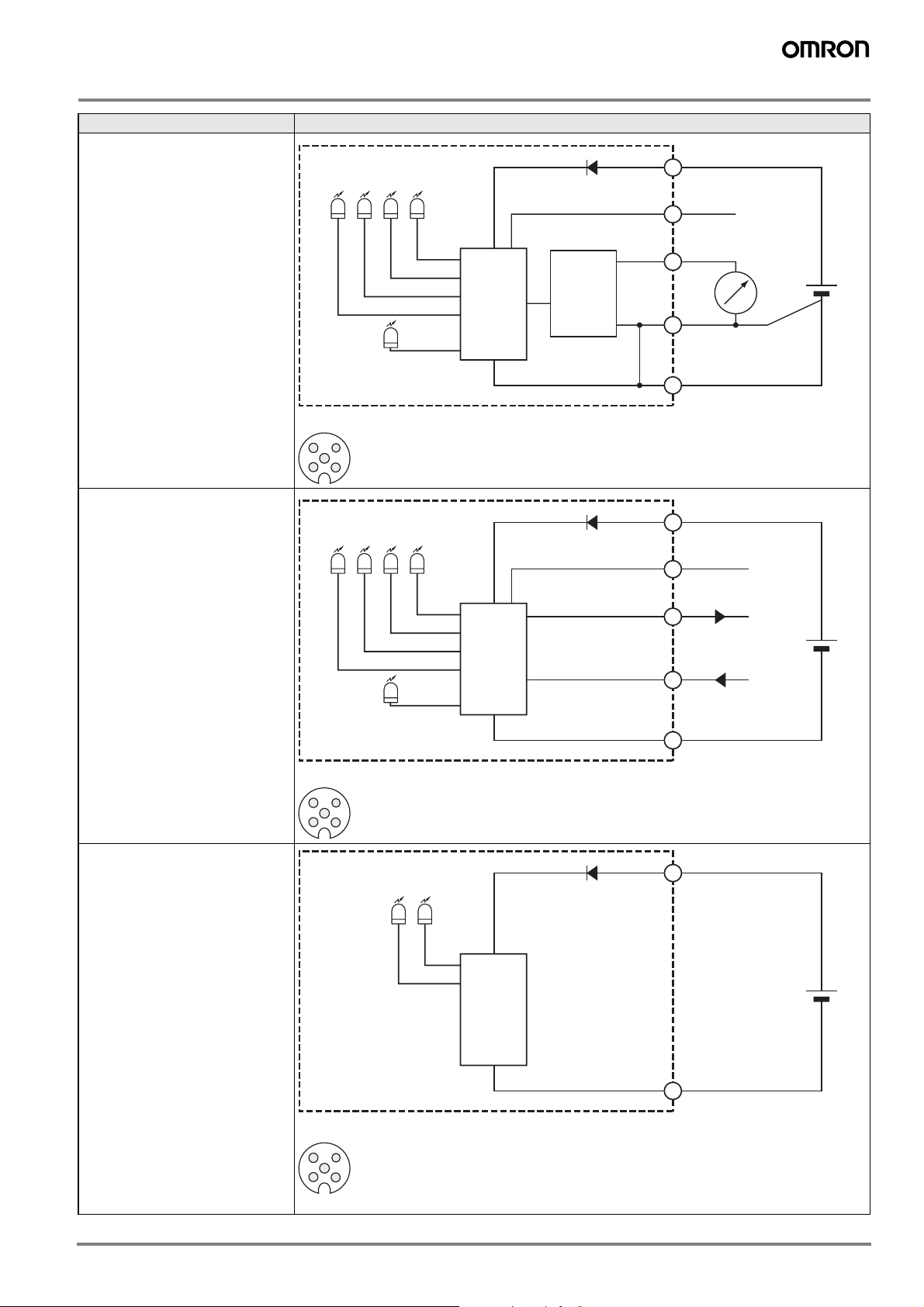
Output circuits
Type Output circuit
Receiver analog output
Out OFF
Out ON
(red)
(green)
Near/Far
(yellow)
Run OK
(yellow)
Power
(green)
Main
circuit
D/A
Converter
1
5
2
4
Brown
Grey
White
Black
24 VDC
+
0-10 V
-
Receiver serial output
Connector pin arrangement
3 4
5
2
1
Out OFF
Out ON
(green)
Near/Far
(yellow)
Run OK
(yellow)
Power
(green)
(red)
Connector pin arrangement
3 4
5
2
1
Main
circuit
3
Blue
Brown
1
5
Grey (Strobe Input)
White TxD
2
Black RxD
4
3
Blue
0 V
24 VDC
0 V
Emitter
Status OK
(yellow)
Power
(green)
Connector pin arrangement
3 4
5
2
1
Note: Terminal 2, 4 and 5 are not used
Main
circuit
1
3
Brown
Blue
24 VDC
0 V
3F3EM Measuring lightcurtain in robust aluminium housing
Page 4

Dimensions
35 mm
Operation
45 mm
Item number
Sensing area
S (mm)
Total length
L (mm)
F3EM-005-150-_ 159 225
F3EM-018-150-_ 147 213
F3EM-005-300-_ 318 384
F3EM-018-300-_ 294 360
F3EM-005-600-_ 636 702
F3EM-018-600-_ 588 654
F3EM-005-900-_ 954 1020
F3EM-018-900-_ 882 948
F3EM-005-2000-D2 2120 2186
F3EM-018-2100-_ 2058 2124
10
S
L
43
12
The F3EM measuring lightcurtain features optical synchronization. This function is provided by the upper beam located on the
opposite side of the connector (see illustration below). During operation this beam must always be kept free. Otherwise it will result
a loss of synchronism between the transmitter and receiver.
For applications where all beams are interrupted there are special
models with synchronization by wire. Please contact your
OMRON representative.
Indicator LEDs
For functions of indicator LEDs please refer to the tables below:
Name of indicator Colour
Power Green
Run ok Yellow
Out on Green
Out off Red
Near/Far Yellow
Name of indicator Colour
Power Green
Status ok Yellow
SYNCHRONISM
S
D
S: Sensing area
D: Pitch
Selector switches (dip switches)
Operation mode, distance setting (analog models) and transmission speed (serial models) can be changed by selector
switches. To access selector switches unscrew the end cap
of the receiver unit:
M12
Note: Selector setting must only be carried out when the receiver is not con-
nected to the power supply.
4 F3EM Measuring lightcurtain in robust aluminium housing
Page 5

Analog Output Models (F3EM-_-AV)
DIP Switch Settings
If F3EM is operated in a distance < 1m, the sensitivity can be
set to NEAR operation. This could be necessary, if multiple
light curtains are installed close to each other, or if the light
curtain detects semi-transparent objects.
The analog output can operate either in STANDARD mode or
INVERTED mode:
• STANDARD mode: 0 V (if no beams is interrupted) to 10 V
(if all beams are interrupted)
• INVERTED mode: 10 V (if no beams is interrupted) to 0 V
(if all beams are interrupted)
Please find the DIP switch setting below:
Switch
1 2 3 4
Distance setting (NEAR
position recommended if
distance is <1 m
ON NEAR ON DECREASING
not used
not used
OFF FAR (default) OFF INCREASING
Operation mode
(default)
Communication protocol
The communication of serial interface provides two possible
operation modes:
• Command-response
• Triggered by external input
A) In command-response mode the command is 1 byte:
Command (hexadecimal) = 'BF'
The light curtain responds with a fixed number of bytes depending on the number of light beams.
E.g. the response of a light curtain with 20 beams is 3 bytes:
1st
87654321
byte
nd
2
16 15 14 13 12 11 10 9
byte
rd
3
0 0 0 0 20191817
byte
The response bytes are composed by each bit representing
the status of each beam in the order as in the example above.
Remaining unused bits in the last byte are set to zero.
Each bit signals:
Analog output value
The output value is related linear to the number of beams interrupted by the object to be measured. For STANDARD
mode:
Output voltage = (10/ n° of optical units) * n° of interrupted
beams [VDC]
If multiple objects are inside the sensing area, the system will
read the total number of beams interrupted accordingly. Referring to the illustration below, the F3EM provides an output
signal in proportion with the sum of A+B:
A
B
Serial Output Models - RS232 (F3EM-_-D2)
The RS232 serial interface of F3EM is specified as follows:
• Full duplex operation
• Data format: 8-N-1 (bit start - 8-bit data - 1-bit stop - no
parity)
Transmission speed setting (Baud Rate)
The baud rate can be set by DIP switch 1 and 2.
@
The baud rate must be set both on the receiver bar
dip-switches as well as the transmitter bar dip-switches to align the timing synchronism of the two bars.
0 = BEAM NOT INTERUPTED
1 = BEAM INTERRUPTED
This drawing shows how the beams
are numbered on the light curtain
As a result each response byte contains 8 beams. The following formula applies for the calculation if the number of response bytes:
number of bytes = INT (number of optical units + 7) / 8)
The maximum number of optical beams that can be managed
is 400.
B) Trigger by external input
Alternatively the response can be forced by signal on the
STROBE input (PNP logic); the light curtain responds on the
serial line with the same protocol explained above.
Measurement method
In order to avoid missing information the light curtain stores interruption of beam signals until the status is sent in the next
protocol response. After the response is sent the interruption
status is reset (all bits to zero).
The beams are scanned sequentially. Therefore it can occur
that a command or trigger arrives before the scan is completed. In this case the scan is interrupted and the status of the
scan before is transferred in the response protocol.
DIP Switch 1 DIP Switch 2 Baud Rate (bps)
OFF OFF 4800
OFF (default) ON (default) 9600 (default)
ON OFF 19200
ON ON 38400
5F3EM Measuring lightcurtain in robust aluminium housing
Page 6

Mounting
Mechanical attachment and alignment
Standard Mounting Bracket (provided with the sensor)
When the mounting bracket is attached to the surface, the mounting
screws can be inserted into the mounting rail of the light curtain. This
allows a vertical position adjustment.
Adjustable Mounting Bracket
Order separately under: F39-TGR-ST-ADJ
For adjustment of the optical axis angle, the adjustable mounting
bracket allows a turning of the light curtain.
Laser Alignment
Order separately under: F39-TGR-LLK2-SB
The laser alignment kit can be snapped onto the light curtain and
emits a high visibility laser beam for ensuring the optimal optical axis
angle adjustment.
Cable connectors
For pin arrangement and connecting the wires refer to Output Circuits.
Material Order code
Size Shape Type Features
M12 General purpose
(screw)
5 wire Brass (CuZn) PVC 2M XS2F-M12PVC5S2M XS2F-M12PVC5A2M
Nut Cable
PUR 2M XS2F-M12PUR5S2M XS2F-M12PUR5A2M
6 F3EM Measuring lightcurtain in robust aluminium housing
Page 7

Precautions
@ WARNING
The F3EM multi-beam photoelectric sensor with beam
evaluation function is not a safety component for ensuring the safety of people which is defined in EC directive (2006/42/EC) or by any other regulations or
standards.
Power Supply Voltage and
Output Load Power Supply Voltage
Do not connect an AC power supply to the Sensor. If AC power (100 VAC or more) is supplied to the Sensor, it may explode or burn. Make sure that the power supply to the Sensor
is within the rated voltage range. If a voltage exceeding the
rated voltage range is supplied to the Sensor, it may explode
or burn.
Operating Environment
Do not use the sensor in locations with explosive or flammable gas. Make sure that the product is operated in accordance
with IP65 standards.
Do not subject the sensor to excessive shock when mounting.
When you use the sensor in the vicinity of an inverter motor,
be sure to connect the protective earth ground wire of the motor to earth. Failure to ground the motor may result in malfunction of the sensor.
Mounting the Sensor
Do not strike the sensor with a hammer or any other tool during the installation of the Sensor.
Cleaning
Never use paint thinners or other organic solvents to clean the
surface of the product
M12 Connector
Always turn OFF the power supply to the sensor before connecting or disconnecting the metal connector. Hold the connector cover to connect or disconnect it.
Secure the connector cover by hand. Do not use pliers; otherwise the connector may be damaged.
If the connector is not connected securely, it may be disconnected by vibration or the proper degree of protection of the
sensor may not be maintained.
7F3EM Measuring lightcurtain in robust aluminium housing
Page 8

In the interest of product improvement, specifications are subject to change without notice.Cat. No. E62E-EN-01A
OMRON EUROPE B.V.
Wegalaan 67-69,
NL-2132 JD, Hoofddorp,
The Netherlands
Phone: +31 23 568 13 00
Fax: +31 23 568 13 88
www.industrial.omron.eu
8 F3EM Measuring lightcurtain in robust aluminium housing
 Loading...