

Page 1
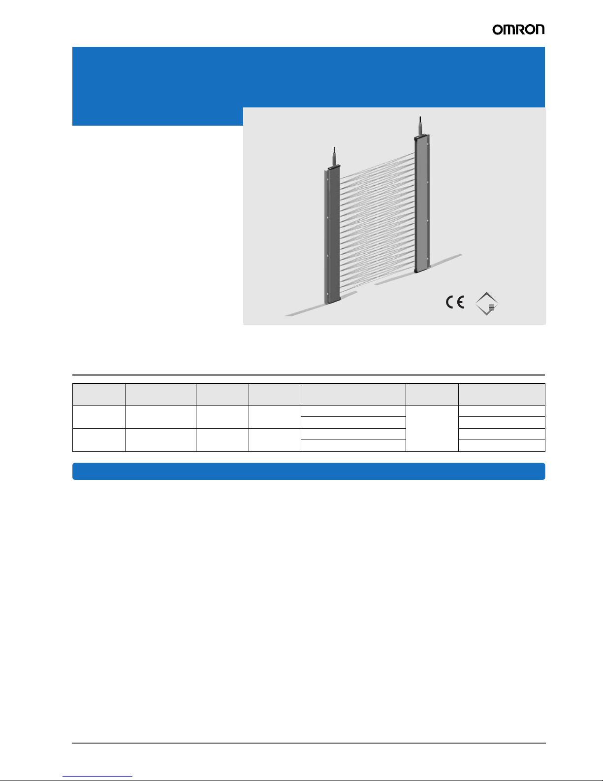
Ultra-flat multi-beam sensor for elevators
K
F3E
• Ultra-flat 9 mm shape for easy design-in in
elevator constructions
• Highest ambient light immunity
(200,000 lux) for installations with direct
sunlight exposition
• Triple crossing resolution maintained
close to zero distance
• Robust aluminum housing
• Ray failure toleration
• Test input
• Built-in amplifier
(operation with 10-30 VDC)
• Fulfills requirements of EN81-70
Designed & manufactured
by
STRAC
LIFT AUTOMATION
Ordering Information
Pitch Detection area channels
120 mm 1800 mm 16 46 5 m pre-wired potential-
40 mm 1800 mm 46 136 5 m pre-wired F3E-46-T1 5M
Number of
optical axis
Connection Output Model number
F3E-16-T1 5M
M8 Connector (4-pin) F3E-16-T6
M8 Connector (4-pin) F3E-46-T6
free output
Features
High reliability and flexibility:
Test input: Function of multi-beam sensor can be tested by transmitter cut off on test signal. A subsequent receiver cut off can be
monitored by control unit.
Ray failure toleration: As soon as one channel is not switching for more than 60 seconds, the F3E identifies a defect and deactivates this channel. The sensor then functions normally again showing the defect channel by a red error LED.
Easy parameterization: By test input of transmitter a parameterization of L-ON/D-ON operation and shading of LED areas is possible. No complicated programming or remote control needed
Potential free output: The F3E provides a wear-free electronic relay output for highest connection flexibility and life-time.
1F3E Multibeam sensor
Page 2
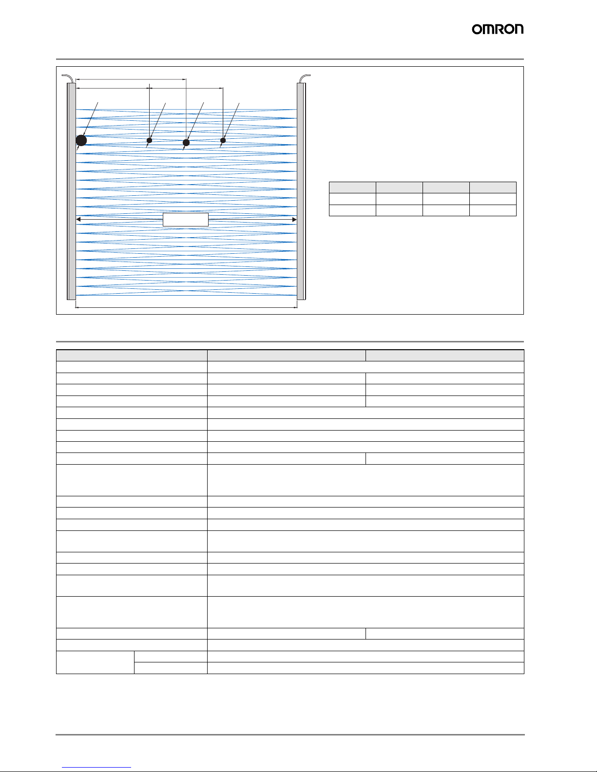
A/2
A/3 A/3
B
C
D
C
High resolution is realized by triple crossing of light
beams.
Automatic sensitivity control ensures steady and op-
timum light power. Even when sensors are operated
in dirty environment or at highest distances, no adjustment is necessary. Sensitivity control ensures
that the high resolution is maintained at small distances close to "zero".
Min. size of recognized objects:
Pitch B D C
120 mm 125 mm 65 mm 45 mm
40 mm 45 mm 35 mm 18 mm
protected area
A = current scanning radius
Rating/Specifications
ItemType F3E-16-T[..] F3E-46-T[..]
Rated sensing distance 0-5 m
Number LEDs 16 46
Number of optical axis 46 136
Resolution 120 mm 40 mm
Vertical detection area
Response time max. 110ms (signal interruption)
Light source (wave length) Infrared LED (880 nm)
Power supply voltage 10-30 VDC
Current consumption max. 120 mA / pair max. 240 mA / pair
Control output Wearless potential free output, 35 V AC/DC max., 150mA max. at 20°C, 100mA max.
Test input / light emission stop function 110 ms max. response time
Ambient light immunity
Ambient temperature -20…+60°C (operation)
EMC conformity/standards 73/23/EWG; 89/336/EWG; 95/16/EG; EN81-1; EN81-2; EN12015; EN12016;
Protective degree IP54
Connection methods Pre-wire type (5 m PVC cable), M8-4-PIN
Indicator LEDs Emitter: power indicator (yellow);
Error status indication Red LED blinking: unstable operation, contamination, max. exceeding sensing dis-
Dimension
1
Weight 880g (connector version), 1040g (cable version)
Material Case Aluminum
1
other sizes available on request
2
Measured at angle of 20°
3
No icing and condensation
1
20-1820 mm
at 60°C, D-ON (parameterization by emitter test input), max. leakage at open contact
0,001mA, contact resistance 4/12 Ohm
2
200.000 lux
EN61000-6-x
Receiver: output indicator (yellow), output indicator (red)
tance
Red LED ON + yellow LED ON: beam channel defect
2070x40,7x9 mm 2000x40,7x9 mm
Cable PVC
3
, -40…+70 (storage)
2 F3E Multibeam sensor
Page 3

Output circuits
Receiver
Status
(yellow)
(red)
Warning
Main
circuit
Connector PIN Arrangement
123
Dimensions
Mounting strap fixation
LED red
LED yellow
light rays
4
potential
free
9
8
I
brown
1
white
2
max. 250 mA /
35 V AC/DC
black
4
blue
3
Load
10 to 30 V DC
Load
alternatively
5
a
Dimension F3E-16… F3E-46…
Transmitter
Power indic
ator
(green)
Main
circuit
Connector PIN Arrangement
a5 25 mm 25 mm
4
123
brown
1
white
2
black (not used)
4
blue
3
test input and programming
10 to 30 V DC
alternatively
0 V
a4 690 mm 650 mm
a3 640 mm 650 mm
a2 690 mm 650 mm
4
a
a1 25 mm 25 mm
h 2070 mm 2000 mm
7
40.75
8
6
h
a3
9
1.5
5
4
3
2
a
2
ø 4.5
1
1
a
5.5
3F3E Multibeam sensor
Page 4

Accessories
Cable connectors
Type Size Cable Material Poles Length (m) LED Nut Order reference
slim line straight M8 PVC 4 5 no brass XS3F-M421-405-A
slim line angled M8 PVC 4 5 no brass XS3F-M422-405-A
robotic cable straight M8 PVC 4 5 no brass XS3F-M421-405-R
robotic cable angled M8 PVC 4 5 no brass XS3F-M422-405-R
Note: Complete portfolio of connector types see OMRON Accessory Datasheet
F3E-Accessories
Item Description Order reference
F3E-Installation Kit S Installation kit for stationary mounting on lift doors F3E-IK-S
F3E-Installation Kit M Installation kit for mounting to mobile doors panels F3E-IK-M
F3E-Power supply Power supply NTR 18/03 for operation with 240VAC/24DC,
buzzer function
F3E-PS1
4 F3E Multibeam sensor
Page 5

Installation Kit S
M5x16
Installation Kit M
The upper mounting angle is screwed
to the top of the door operator.
The lower mounting angle is screwed
to the underside of the door sill.
Then the vertical mounting angle
- with the sensor unit already screwed onto it is inserted with its conical end into the slot
in the lower mounting angle.
M4x10
sensor unit with
mounting strap
fixation
M4x12
M4x12
vertical
mounting angle
cone
upper
mounting
angle
vertical
mounting
angle
sensor unit with
mounting strap
fixation
lower
mounting
angle
M6x16
door panel
mounting clamps
sensor unit with
strap fixation
5F3E Multibeam sensor
Page 6

Precautions
@ WARNING
The F3E multi-beam photoelectric sensor is not a
safety component for ensuring the safety of people
which is defined in EC directive (2006/42/EC) or by
any other regulations or standards.
Power Supply Voltage and
Output Load Power Supply Voltage
Do not connect an AC power supply to the Sensor. If AC power (100 VAC or more) is supplied to the Sensor, it may explode or burn. Make sure that the power supply to the Sensor
is within the rated voltage range. If a voltage exceeding the
rated voltage range is supplied to the Sensor, it may explode
or burn.
Operating Environment
Do not use the Sensor in locations with explosive or flammable gas. Make sure that the product is operated in accordance
with IP54 standards.
Do not subject the multi-beam sensor to excessive shock
when mounting.
When you use the multi-beam sensor in the vicinity of an inverter motor, be sure to connect the protective earth ground
wire of the motor to earth. Failure to ground the motor may result in malfunction of the sensor.
Mounting the Sensor
Do not strike the Photoelectric Sensor with a hammer or any
other tool during the installation of the Sensor.
Cleaning
Never use paint thinners or other organic solvents to clean the
surface of the product
M8 Connector
Always turn OFF the power supply to the Sensor before connecting or disconnecting the metal connector. Hold the connector cover to connect or disconnect it.
Secure the connector cover by hand. Do not use pliers; otherwise the connector may be damaged.
If the connector is not connected securely, it may be disconnected by vibration or the proper degree of protection of the
Sensor may not be maintained.
In the interest of product improvement, specifications are subject to change without notice.Cat. No. E48E-EN-01A
OMRON EUROPE B.V.
Wegalaan 67-69,
NL-2132 JD, Hoofddorp,
The Netherlands
Phone: +31 23 568 13 00
Fax: +31 23 568 13 88
www.industrial.omron.eu
6 F3E Multibeam sensor
 Loading...