

Page 1
F3C-AA42-@@
A-271F3C-AA42-@@
Distance settable Photoelectric Sensor for conveying applications
F3C-AA42-@@
• Background influences are eliminated
by a unique optical system for setting
the detection distance
• Small black-/white-error
• Sensing distance mechanically adjustable:
BGS setting distance: 150 - 900 mm
Detecting distance: 0 - 750 mm
• Small housing-case specially designed for conveyer-application (only
8 mm of thickness on the top of the
housing)
• Minimal blind-zone through additional
receiver
• Sensitivity adjustment for near side
detector
• Integrated jamming control unit
(Only F3C-AA42-3J)
Stable Detection
Background-Suppression-Type
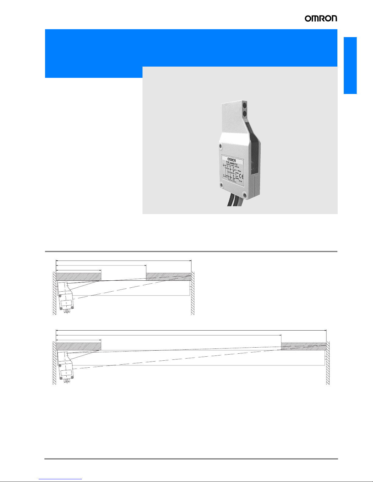
Application
Example for sensing characteristics (detection
area) in conveyor application and description of
setting the minimum and maximum Background
Suppression (BGS) function.
450 (min BGS-setting distance)
300 (sensing distance)
150 (min detectable object size)
900 (max BGS-setting distance)
750 (sensing distance)
150 (min detectable object size)
Page 2
A-272 Standard Photoelectric Sensors
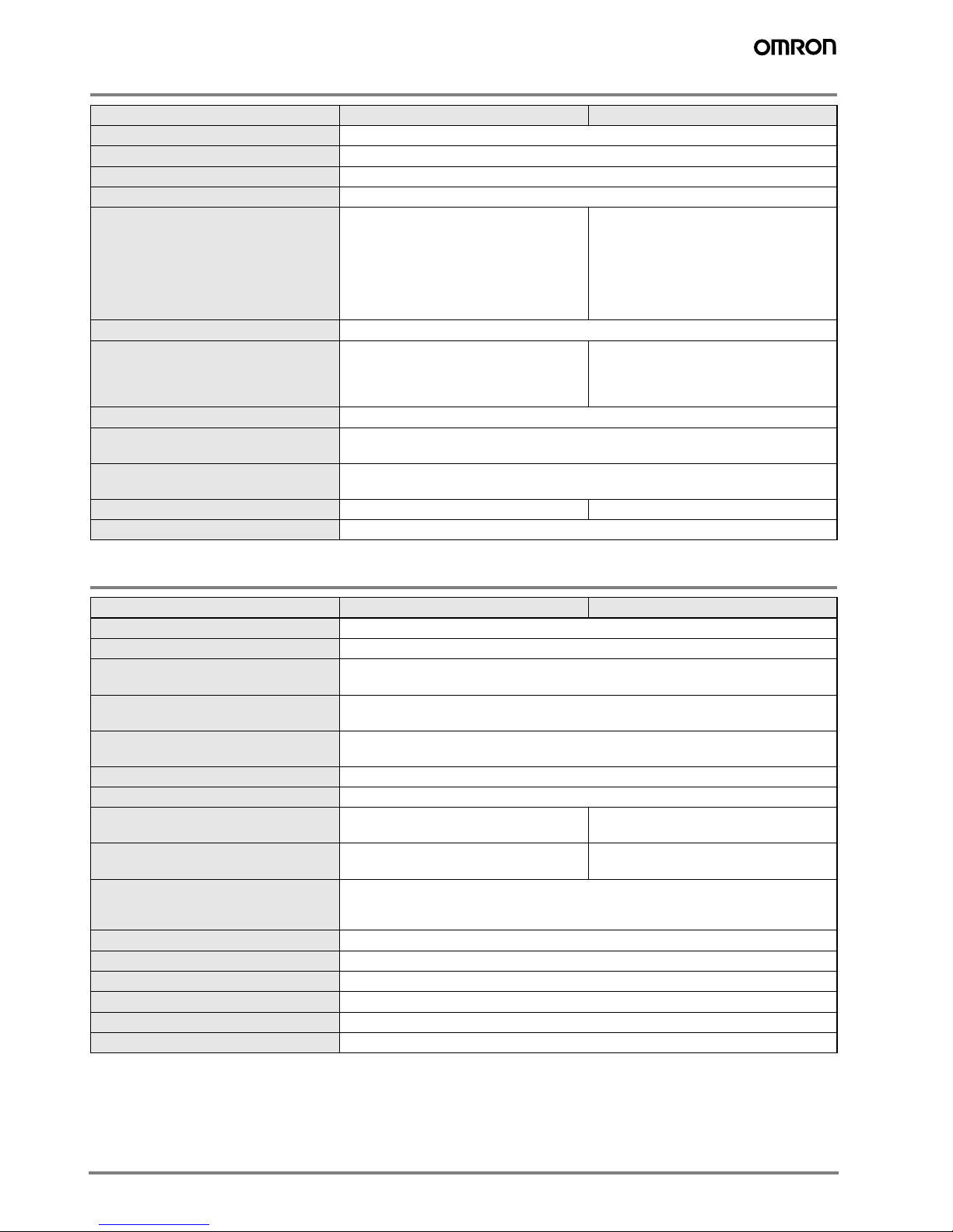
Specifications
Ratings / Characteristics
Item F3C-AA42-1 F3C-AA42-3J
LED for emitter Infrared LED (wavelength 880 nm)
Sensitivity adjustment for BGS 6-turn endless adjustor
Sensitivity adjustment for near side detector 1-turn potentiometer
Typical adjustment range 0 ... 200 mm (Kodak -Gray-Card / 90 % reflectivity)
Connecting method / cable length Prewired
Power supply (M12 plug) / 30 cm
(4 x 0.34 mm²)
Prewired
Power supply (M12 plug) / 30 cm
(4 x 0.34 mm²)
Neighbg. sensor (M12 socket) / 150 cm
(4 x 0.34 mm²)
Valve output (with socket) / 200 cm
(2 x 0.35 mm²)
Output configuration PNP
Control output Dark-on Dark-on
Jamming control output / input via M12
moulded plug / socket, prewired valve con-
trol output
Circuit protection Load short-circuit protection and mutual interference suppression
LED stability- / function indication Permanent light: Object detected / stable function
Blinking light: Object detected / instable function
Materials Case: ABS plastic
Lenses: Acrylic, PMMA
Weight 60 g 180 g
Attachment Screwdriver for adjustment, instruction manual
Item F3C-AA42-1 F3C-AA42-3J
Power supply voltage 10 to 30 V DC; ripple 10 % max.
Current consumption 40 mA max.
Settable distance for background suppres-
sion
150 ... 900 mm
(Kodak -Gray-Card / 90 % reflectivity, 200 x 200 mm)
Detecting distance (recommended) 0 ... 750 mm
(Kodak -Gray-Card / 90 % reflectivity, 200 x 200 mm)
Hysteresis BGS-receiver Max. 2 % of adjusted distance
Energetic receiver:Max. 20 % of adjusted distance
Reflectivity (Black-/white-error) 40 mm diameter at 750 mm detection distance
Response time max. 10 ms for both operation and release
Control / Valve output current --- 150 mA max. at 30 V DC (voltage drop max.
2.0 V)
Jamming supply current --- 5 A amx. at 30 V DC (max. 30 sensor may
be connected for jamming control)
Ambient illumination Incandescent lamp:Illumination on optical spot: max. 5,000 lx
Sunlight: Illumination on optical spot: max 5,000 lx
Fluorescent lamps:max. 5,000 lx
Ambient temperature Operating: -5 °C to +55 °C (no icing)
Insulation resistance 20 MΩ min. (at 500 V DC)
Dielectric strength 1,000 V AC, 50/60 Hz for 1 min
Vibration resistance 10 ... 55 Hz, amplitude = +/-1.5 mm (or 300 m/s²) for 2 hrs. each in X, Y and Z-direction
Shock resistance Pulse shape: half-sine, peak acceleration: 300 m/s², duration of pulse: 18 ms
Enclosure rating IP54
Page 3

A-273F3C-AA42-@@
F3C-AA42-@@
Engineering Data
Spotdiameter via detection distance
*1
Operating range
*1
Angle Characteristics of F3C-BGS-Conveyor Sensor
Vertical detection
*1
Horizontal detection
*1
*1. Reflecting object: Kodak-Gray-Card / 90 % reflectivity / 200 mm x 200 mm
Detection dist./cm
0 1020304050607080
4.5
4
3.5
3
2.5
2
1.5
1
0.5
0
Spot-diameter/cm
Sensing dist./cm
0 10203040506070
1.5
1
0.5
0
-0.5
-1
-1.5
-Y / +Y (cm)
Sn = 20 cm
Sn = 45 cm
Sn = 60 cm
Sn = 75 cm
Angle / ˚
-40 -30 -20 -10 0 10 20 30 40
3.5
3.0
2.5
2.0
1.5
1.0
0.5
0.0
-0.5
-1.0
-1.5
-2.0
%-ual change of sens.-dist.
Angle / ˚
-40 -30 -20 -10 0 10 20 30 40
3.0
2.5
2.0
1.5
1.0
0.5
0.0
%-ual change of sens.-dist.
Page 4

A-274 Standard Photoelectric Sensors
Nomenclature
Black-/White-Error (related to Kodak-Gray-Card 90 %)
*1. Reflecting object: Kodak-Gray-Card / 90 % reflectivity / 200 mm x 200 mm
BGS Setting distance
15 cm 30 cm 45 cm 60 cm 75 cm
80
70
60
50
40
30
20
10
0
Sensing distance / cm
3%
6%
18%
90%
70
80
90
10
20
30
40
50
60
45
374
32
4.2
42
4
90
18
Pos. Functional description
10 IR-emitting LED
20 Near-side detector
30 Optical module
40 Black coloured adjustment knob for setting distance (6-turns)
50 LED light-/stability indicator
60 Yellow knob for near-side adjustment (1-turn)
70 M12-plug for power supply
80 M12-socket for neighbouring sensor (Only 3J-type)
90 Valve cable (Only 3J-type)
Page 5

A-275F3C-AA42-@@
F3C-AA42-@@
Operation
Jamming control connections and principal circuit (Only F3C-AA42-3J)
Output con-
figuration
Mode switch
Output tran-
sistor
Output circuit
F3C-AA42-1 F3C-AA42-3J
PNP Dark-ON
ON when
light is not re-
ceived
Timing Chart
F3C-AA42-3J Plug for power supply Socket for neighbouring sensor Cable for valve
No. 1 / bn +Vcc(10 ... 30 V DC) +Vcc(10 ... 30 V DC) - / No. 2 / wt Control output Control input - / No. 3 / bl 0 V 0 V - / No. 4 / bk Release input Release output - / bn (bk) - / - - / - + Valve output
bl (bk-ye) - / - - / - 0 V / Valve
F3C-AA42-1
1 / + Vcc
4 / ..... NC
2 / Output
3 / .... 0 V
bn
bk
wt
bl
Photoelectric
Sensor
bn
bk
wt
bl
1
4
2
3
F3C-AA42-3J
1 / ...+ V cc
4 / Release
2 / .. Output
3 / ....... 0 V
bn
bk
wt
bl
+ Vcc ...
Release
Input .....
0 V ........
0 V
+ Valve
bn (bk-ye)
bl (bk)
Photoelectric
Sensor
ON
OFF
Light received
Light is not received
ON
OFF
Operate
Release
Light indicator
(red)
Output transistor
Load (relay)
0V
Release
+Valve/bn (bk)
-Valve/bl(bk-ye)
+Valve/bn (bk)
-Valve/bl(bk-ye)
+Valve/bn (bk)
-Valve/bl(bk-ye)
1
2
4
3
bn
bk
wt
bl
bn
bk
wt
bl
4
2
3
Sensor 1Sensor 2... Sensor 30
+ VCC
1
2
4
3
bn
bk
wt
bl
bn
bk
wt
bl
1
4
2
3
1
2
4
3
bn
bk
wt
bl
bn
bk
wt
bl
1
4
2
3
Control ->
0V
Release
+ VCC
Control ->
0V
Release
+ VCC
Output
Page 6

A-276 Standard Photoelectric Sensors
Precautions
Installation and adjustment
1. Switch off power supply
2. Connect sensor 1 to the power supply station. Make sure
that the correct voltage value is adjusted. Max. 30 sensors
can be connected together. The power supply is linked
from oneswitch to the other via M12-connector.
3. Fix sensor, by using an adequate mounting bracket, in the
middle of between the conveyer rolls and twist the case
slighty backward (2-5°)
4. Turn black-coloured distance adjustment knob (Pos. 40)
and yellow coloured screw (Pos. 60) for near-side-detection carefully counterclockwise until minimum position is
reached
5. Switch on power supply
6. At first adjust the sensing distance by turning the black
knob, that at least 5 % of the switching distance value can
be guaranteed related to the reflecting background (check
by using a Kodak Gray Card with 90 % reflectivity)
7. Activate near-side detector by turning the yellow-coloured
knob (Pos. 60) clockwise - the red LED should not blink
and should light permanently when the object is detected.
Otherwise increase sensitivity by turning the yellow knob
clockwise
8. When object is removed, the red LED should not light or
blink
Recommended adjustment
The adjusted sensing-distance of the near-side detector
should not exceed the BGS-Settingdistance.
Correct operation
The moving direction of the
sensor or object
should be preferably along the
optical axis of the
light beam. Lateral approach is
also possible. Movement from the top to the bottom or opposite can case malfunction and should be avoided.
In case of installing two sensors facing each other, the optical
axis should be moved to prevent any mutual interference.
Avoid influences of any strong ambient light sources that can
decrease the sensitivity of the sensor or cause instable working condition.
Connections and precautions
If the input/output lines of the photoelectric sensor are placed
in the same conduit or duct as power lines or high-voltage
lines, the photoelectric sensor could be induced to malfunction, or even be damaged by electrical noise. Either separate
the wiring or use shielded lines as input/output lines to the
photoelectric sensor.
The cord connected to the Sensor can be extended up to
50 m provided that the diameter of each wire is 0,3 mm² minimum.
Maintenance
Normally the F3C doesn’t need any maintenance. Only the
optical surfaces should be cleaned from time to time by using
a soft cloth.
Startup Operation
A maximum of 300 ms is required from the time power is
turned on until F3C is able to detect objects. If power is supplied to the loads and the F3C from different sources, turn on
power to the F3C first.
Water resistivity
Do not use F3C in water, in rain or outdoors.
Accessories
Standard mounting bracket for easy installation. Ordering
number E39-L40
Movement of object
LED (light received)
Light beam
Sensing distance
adjuster
50
58
60
40 52
36.26.6 7
405
12
22
5.6
In the interest of product improvement, specifications are subject to change without notice.
ALL DIMENSIONS SHOWN ARE IN MILLIMETERS.
To convert millimeters into inches, multiply by 0.03937. To convert grams into ounces, multiply by 0.03527.
Cat. No. E27E-EN-01
 Loading...