

Page 1

PNSPO!
Model F39-MC11(ver. 3)
Setting Console
INSTRUCTION MANUAL
Thank you for selecting OMRON product. This manual primarily
describes precautions required in installing and operating the product.
Before operating the product, read this manual thoroughly to acquire
sufficient knowledge of the product. For your convenience, always keep
this manual at hand.
©OMRON Corporation 2001-2003 All Rights Reserved.
i
Read and Understand this Instruction Manual
Please read and understand this instruction manual before storing,
installing, programming, operating, maintaining, or disposing of the
products. Please consult your OMRON representative if you have any
questions or comments.
Warranty, Limitations of Liability
WARRANTY
OMRON's exclusive warranty is that the products are free from
defects in materials and workmanship for a period of one year (or
other period if specified) from date of sale by OMRON.
OMRON MAKES NO WARRANTY OR REPRESENTATION,
EXPRESS OR IMPLIED, REGARDING NON-INFRINGEMENT,
MERCHANTABILITY, OR FITNESS FOR PARTICULAR PURPOSE
OF THE PRODUCTS. ANY BUYER OR USER ACKNOWLEDGES
THAT THE BUYER OR USER ALONE HAS DETERMINED THAT
THE PRODUCTS WILL SUITABLY MEET THE REQUIREMENTS OF
THEIR INTENDED USE. OMRON DISCLAIMS ALL OTHER
WARRANTIES, EXPRESS OR IMPLIED.
LIMITATIONS OF LIABILITY
OMRON SHALL NOT BE RESPONSIBLE FOR SPECIAL,
INDIRECT, OR CONSEQUENTIAL DAMAGES, LOSS OF PROFITS
OR COMMERCIAL LOSS IN ANY WAY CONNECTED WITH THE
PRODUCTS, WHETHER SUCH CLAIM IS BASED ON CONTRACT,
WARRANTY, NEGLIGENCE, OR STRICT LIABILITY.
In no event shall the responsibility of OMRON for any act exceed the
individual price of the product on which liability is asserted.
IN NO EVENT SHALL OMRON BE RESPONSIBLE FOR
WARRANTY, REPAIR, OR OTHER CLAIMS REGARDING THE
PRODUCTS UNLESS OMRON'S ANALYSIS CONFIRMS THAT THE
PRODUCTS WERE PROPERLY HANDLED, STORED, INSTALLED,
AND MAINTAINED AND NOT SUBJECT TO CONTAMINATION,
ABUSE, MISUSE, OR INAPPROPRIATE MODIFICATION OR
REPAIR.
Page 2

- ii -
Application Considerations
SUITABILITY FOR USE
OMRON shall not be responsible for conformity with any standards,
codes, or regulations that apply to the combination of the products in
the customer's application or use of the products.
At the customer's request, OMRON will provide applicable third party
certification documents identifying ratings and limitations of use that
apply to the products. This information by itself is not sufficient for a
complete determination of the suitability of the products in
combination with the end product, machine, system, or other
application or use.
The following are some examples of applications for which particular
attention must be given. This is not intended to be an exhaustive list
of all possible uses of the products, nor is it intended to imply that the
uses listed may be suitable for the products:
• Outdoor use, uses involving potential chemical contamination or
electrical interference, or conditions or uses not described in this
instruction manual.
• Nuclear energy control systems, combustion systems, railroad
systems, aviation systems, medical equipment, amusement
machines, vehicles, and installations subject to separate
industry or government regulations.
Systems, machines, and equipment that could present a risk to
life or property.
Please know and observe all prohibitions of use applicable to the
products.
NEVER USE THE PRODUCTS FOR AN APPLICATION INVOLVING
SERIOUS RISK TO LIFE OR PROPERTY WITHOUT ENSURING
THAT THE SYSTEM AS A WHOLE HAS BEEN DESIGNED TO
ADDRESS THE RISKS, AND THAT THE OMRON PRODUCTS ARE
PROPERLY RATED AND INSTALLED FOR THE INTENDED USE
WITHIN THE OVERALL EQUIPMENT OR SYSTEM.
PROGRAMMABLE PRODUCTS
OMRON shall not be responsible for the user's programming of a
programmable product, or any consequence thereof.
- iii -
Disclaimers
CHANGE IN SPECIFICATIONS
Product specifications and accessories may be changed at any time
based on improvements and other reasons.
It is our practice to change model numbers when published ratings or
features are changed, or when significant construction changes are
made. However, some specifications of the products may be
changed without any notice. When in doubt, special model numbers
may be assigned to fix or establish key specifications for your
application on your request. Please consult with your OMRON
representative at any time to confirm actual specifications of
purchased products.
DIMENSIONS AND WEIGHTS
Dimensions and weights are nominal and are not to be used for
manufacturing purposes, even when tolerances are shown.
ERRORS AND OMISSIONS
The information in this instruction manual has been carefully checked
and is believed to be accurate; however, no responsibility is assumed
for clerical, typographical, or proofreading errors, or omissions.
Meanings of Signal Words
The following signal words are used in this instruction manual.
WARNING
Indicates a potentially hazardous situation which,
if not avoided, will result in minor or moderate
injury, or may result in serious injury or death.
Additionally there may be significant property
damage.
CAUTION
Indicates a potentially hazardous situation which,
if not avoided, may result in minor or moderate
injury or in property damage.
Page 3
- iv -
Meanings of Alert Symbols
The following alert symbols are used in this instruction manual.
Indicates the possibility of explosion under specific
conditions.
Alert statements in this Instruction Manual
The following alert statements apply to the products in this instruction
manual. Each alert statement also appears at the locations needed in
the manual to attract your attention.
WARNIG
F39-MC must be managed and used only by qualified persons.
Operation by un-qualified persons could create a hazardous condition
which may lead to a loss of safety function.
After the changing the setting of the sensor, a start-up check must
be conducted. Normal operation can only be allowed after safety
is confirmed.
In order prevent access to a dangerous area, fixed barrier guards must
be placed in fixed blanked areas.
Failure to do so may result in serious injury.
Use of floating blanking function involves a change of the safety distance.
Always recalculate and re-measure the safety distance to confirm that it
meets the applicable standards, after the change.
Failure to do so may cause the machine to fail to stop before an operator
reaches a dangerous area, and may result in serious injury.
A change of the setting can only be done under observance of laws/
standards which are related to safe operation of the product.
CAUTION
Do not connect the F39-MC to any equipment other than for
what it intended to be used with.
- v -
Precautions for Safe Use
Please observe the following precautions for safe use of the products.
• Do not connect to voltage exceeding the stated values. Doing so
may cause damage to the product.
• Do not expose the F39-MC to water on the product. Doing so
may cause damage to the product.
Precautions for Correct Use
Please observe the following precautions to prevent failure to operate,
malfunctions, or undesirable effects on product performance.
• Always power OFF the sensor when connecting or
disconnecting the F39-MC11.
• When F39-MC is not in use, disconnect it from the sensor.
Page 4

- vi -
Table of Contents
1 DESCRIPTION .............................................................................. 1
1.1 Outline of operation procedure .................................................2
1.2 Available function and Sensor serial number ...........................3
2 RATING ......................................................................................... 4
3 NOMENCLATURE......................................................................... 5
4 WIRING/CONNECTION ................................................................ 7
4.1 Mounting branching connector .................................................7
4.2 Diagram for Wiring of Branching Connector.............................8
4.3 Connecting F39-MC .................................................................9
5 POWER ON................................................................................. 10
6 FUNCTION SELECTION..............................................................11
7 CHANNEL SELECTION .............................................................. 12
8 MONITOR/SET............................................................................ 14
8.1 Fixed blanking ........................................................................16
8.2 Floating blanking ....................................................................21
8.3 Auxiliary output .......................................................................24
8.4 Output2 ...................................................................................24
8.5 External indicator output .........................................................27
8.6 External device monitoring .....................................................30
8.7 Start interlock.......................................................................... 31
8.8 Restart interlock...................................................................... 32
8.9 Threshold adjustment ............................................................. 33
8.10 Setting initialization.................................................................34
8.11 ID setting ................................................................................ 35
8.12 Threshold teach......................................................................36
8.13 Error log view..........................................................................40
9 COPY .......................................................................................... 41
9.1 Upload (Copy Sensor data to F39-MC) .................................. 42
9.2 Download (Copy F39-MC data to Sensor) ............................. 43
9.3 Bank Lock (Prohibit overwriting to bank data) ........................44
10 PROTECT ............................................................................. 45
10.1 Setting lock............................................................................. 46
10.2 Change password...................................................................47
10.3 Setting limitation.....................................................................48
11 DISCONNECT F39-MC......................................................... 50
12 MC11 ERROR CODES ......................................................... 51
13 TROUBLESHOOTING .......................................................... 52
ANNEX1 INDEX .................................................................................. 53
ANNEX2 FUNCTION LIST (according to sensor type) ....................... 56
ANNEX3 ERROR CODE LIST ............................................................ 60
ANNEX4 FUNCTION SETTING CARD ............................................... 61
0
Page 5

- 1 -
1 DESCRIPTION
The Setting consol Model F39-MC11 (hereafter referred to as F39-MC)
can be connected to Safety Light Curtain Series—Model F3SN,
Multi-beam Safety Sensor series—Model F3SH, and Area Scanner
series—Model F3ZN. The F39-MC allows you to change or monitor the
setting of these sensors.
Available setting functions are as follows;
Function Setting F3SN F3SH F3ZN
Fixed blanking
Floating blanking
Auxiliary output
Output2
External indicator output
External device monitoring
Start interlock
Restart interlock
Threshold adjustment
Setting initialization
ID setting
Threshold teach *
Monitor/
Set
Error log view
Copy Upload
Download
Bank lock
Protect Setting lock
Change password
Setting limitation
: Accessible
* For the sensor having the specific serial number, this function is
unavailable.
Refer to “ 1.2 Available function and Sensor serial number ”.
- 2 -
1.1 Outline of operation procedure
Shown in the following flow chart.
⑨Power on sensor(s) and
confirm correct function
by the test.
Outline of operation
procedure
Setting completed.
(Able to normal use)
See section 6
See section 7
See section 4.1
See section 4.3
See section 5
①Mount branching connector
②Connect cable and F39-MC
③Power on both sensor(s)
and F39-MC
④Select function
(MONITOR/SET, COPY,
PROTECT)
⑤Select channel of sensor
to be set
⑥Select sensor function to
be set, and change value
⑦Send changed setting to
sensor(s)
⑧Power OFF, and detach
F39-MC and cable
See section 8 to 10
See section 11
See section 8 to 10
Page 6

- 3 -
1.2 Available function and Sensor serial number
For the sensor having the specific serial number, there are some
unavailable functions in the functions of the F39-MC11.
Check the serial number on the type label of the sensor for both emitter
and receiver to make sure available functions for the sensor.
New functions are divided into two function groups, the functional group
A and the functional group B, by the serial number of the sensor.
Refer to “ANNEX2 FUNCTION LIST (according to sensor type)”(Page
56) about functions corresponding to each group.
The method to distinguish between the functional group A and the
functional group B is as follows.
The functional group A
The following serial numbers correspond to the functional group A.
Serial number:
aaaa402, aaaa502, aaaa602, aaaa702, aaaa802, aaaa902,
aaaaX02, aaaaY02, aaaaZ02, or aaaabcc
'aaaa' can be any numeric characters.
'b' can be any alphanumeric characters.
'cc' is greater than '03'
The functional group B
The following serial numbers correspond to the functional group B.
Serial number:
0001803~, aaaa903, aaaaX03, aaaaY03, aaaaX03, or aaaabcc
'aaaa' can be any numeric characters.
'b' can be any alphanumeric characters.
'cc' is greater than '04'.
- 4 -
2 RATING
Models
Items
F39-MC11
Applicable sensor F3SN, F3SH, F3ZN Series
Communication method Specified method
Communication
connecting method
RS-485
Power supply
24VDC±10%
(share sensor’s power supply)
Current consumption 55mA maximum
Ambient temperature
(during operation)
-10℃ to 55℃
(with no freezing)
Ambient temperature
(during storage)
-25℃ to 65℃
Ambient humidity 25 to 85%RH
(with no condensation)
Insulation resistance
20MΩ min.(at 500VDC)
Dielectric strength voltage 1,000VAC at 50/60Hz for 1min.
Case ABS
Material
Window Polycarbonate
Weight Approx. 87g (without accessories)
Approx. 360g (when packed)
Accessories Branching connector, Cable(2m),
Connector cap, Instruction manual
Page 7
- 5 -
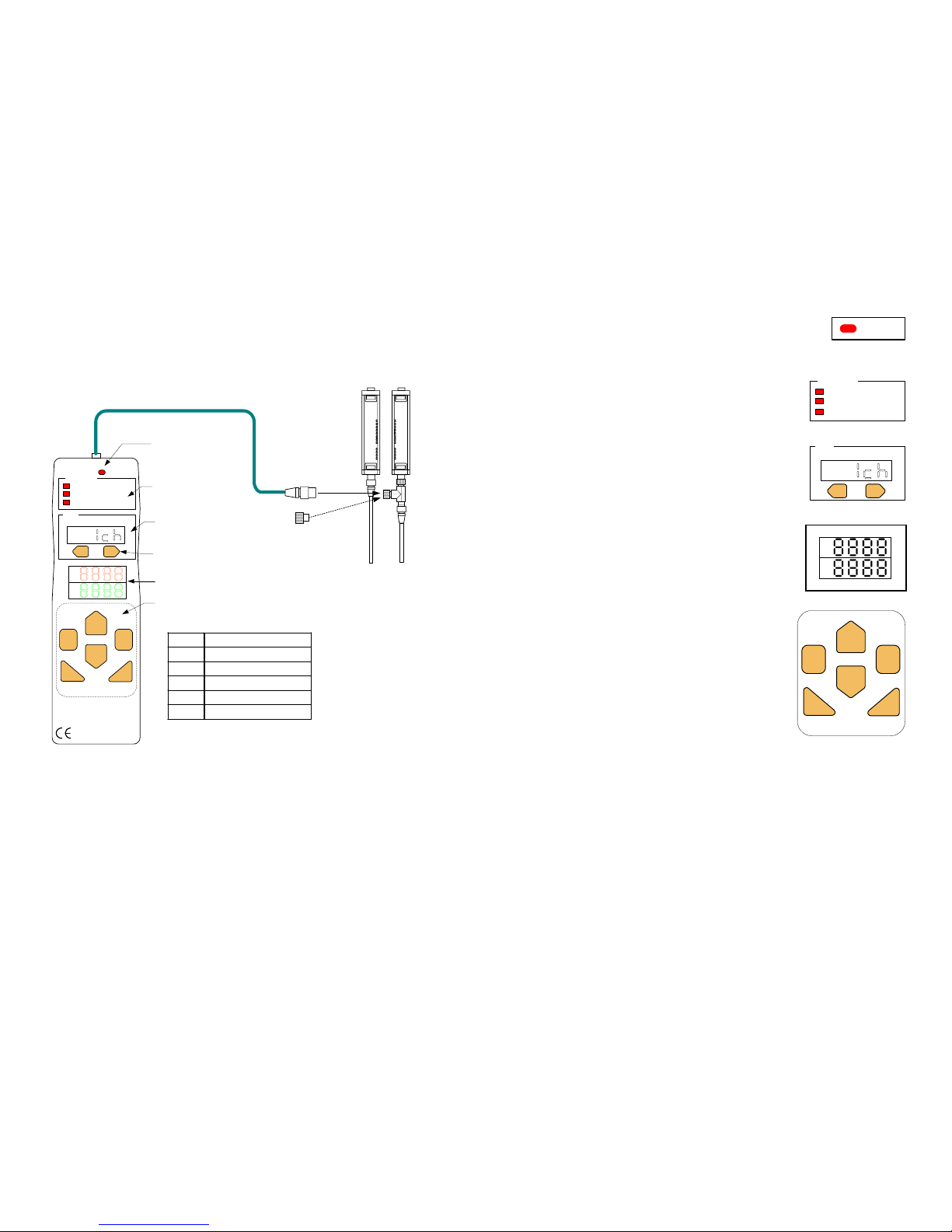
3 NOMENCLATURE
Cable (Length: 2m)
+
|
CONNECT
PNSPO
+
-
MONITOR / SET
COPY
PROTECT
MENU
Setting Console
F39-MC11
CANCEL ENTER
Communication
connection indicator
(CONNECT)
DOWN
UP
RL
Function indicators
(FUNCTION)
Channel display
(CH)
Channel keys(CH)
Mode display
Operation keys
UP Change mode, increase value
DOWN Change mode, decrease value
RIGHT digit position down
LEFT digit position up
CANCEL To cancel
ENTER To se t
Branching
Connector
Sensor
(F3SN, F3SH, or
F3ZN series)
MADE IN JAPAN
FUNCTION
CH
Connector Cap
Please set this to branching
connector when F39-MC is
not in use.
Brief description of Operation keys
- 6 -
+
-
CANCEL ENTER
DOWN
RL
UP
MONITOR / SET
COPY
PROTECT
FUNCTION
3.1 Communication connection indicator (CONNECT)
This indicator will light up when F39-MC is
connected to the sensor.
F39-MC cannot be used when this indicator is not lit.
3.2 Function indicators (FUNCTION)
The indicator of the function being set is lit.
3.3 Channel display(CH) and channel keys
Using +/- keys, select sensor to be set by
F39-MC.
Number of selected channel appears on
display.
3.4 Mode display
Displays function and value when making a
setting.
Basically the top row indicates Setting
function and the bottom row Setting value.
3.5 Operation keys
Used for mode change, setting and
canceling.
+
|
CH
CONNECT
Page 8
- 7 -
4 WIRING/CONNECTION
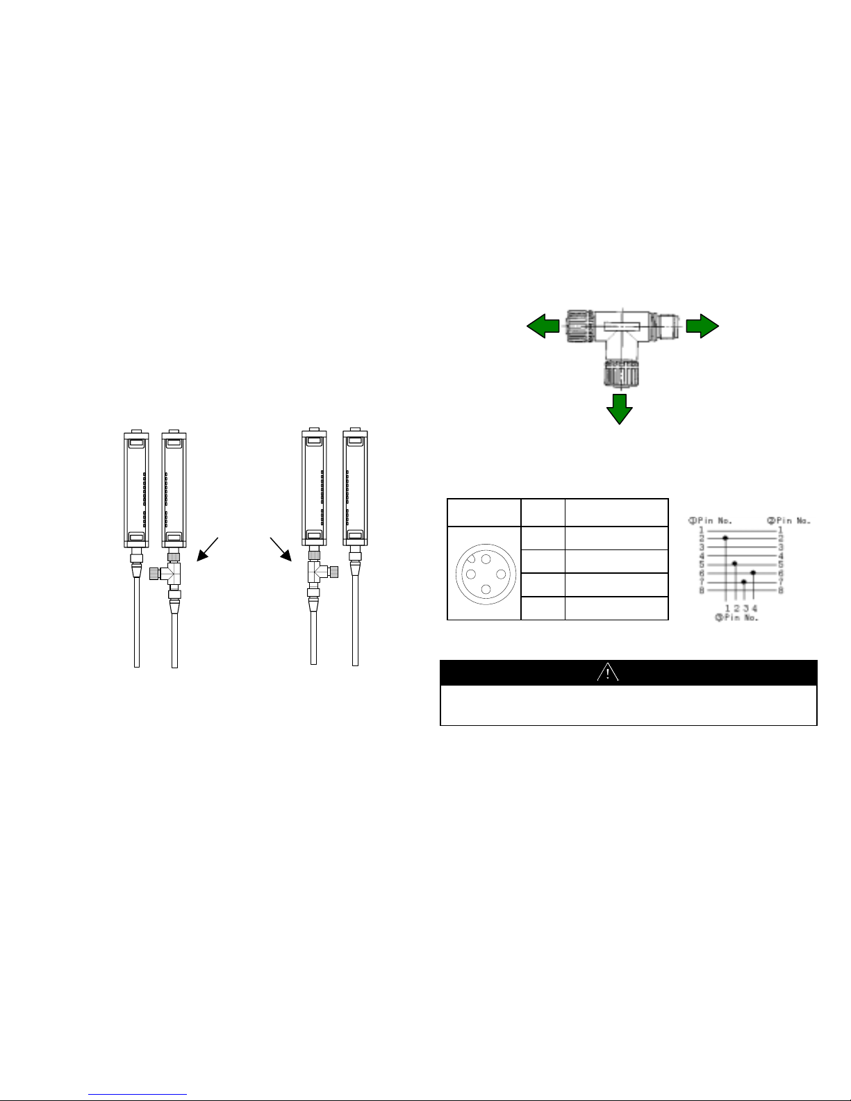
4.1 Mounting branching connector
Mount a branching connector to sensor. The connector can be
mounted either on emitter or receiver.
When mounted on receiver When mounted on emitter
Branching
connector
Emitter Receiver
Emitter Receiver
- 8 -
4.2 Diagram for Wiring of Branching Connector
Front View
Pin
No.
Signal
1
+24 V(24VDC)
2 RS-485(A)
3 0V
4 RS-485(B)
CAUTION
The F39-MC receives its power from the sensor. Select a power supply
with sufficient current to allow for the additional consumption of the
F39-MC (55mA maximum).
①8Pin female
To sensor
②8Pin male
To po w er
supply circuit
③4Pin female
To F3 9 -MC
2
4
31
Page 9
- 9 -
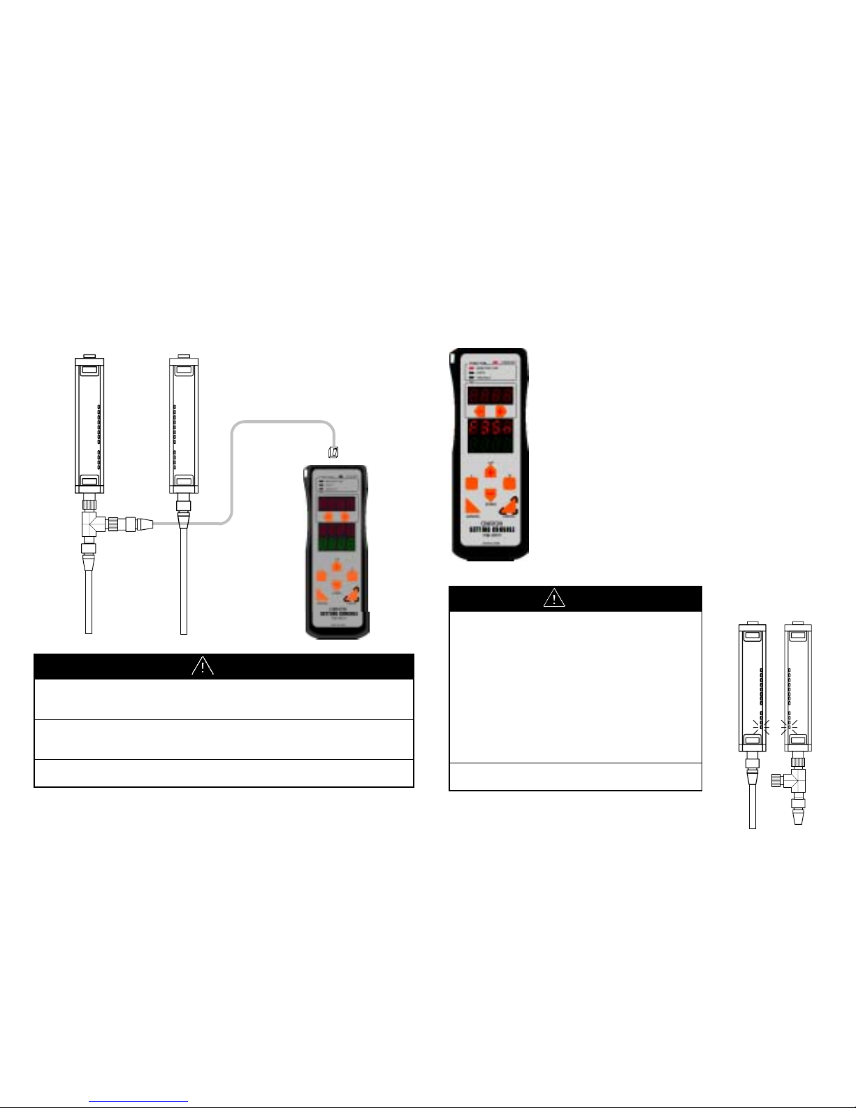
4.3 Connecting F39-MC
Insert M12 connector of the cable into Branching connector and the
other end into the F39-MC11.
CAUTION
Do not connect 2 or more F39-MC to one pair of sensor. Normal
operation cannot be achieved. Also, combined use of F39-MC and
F3ZP, area scanner controller, is not allowed.
When F39-MC is not in use, the cable and F39-MC must be removed
and Branching connector must be covered with connector cap (Model
XS2Z-12).
When connecting or disconnecting the F39-MC, be sure that the power
is OFF.
- 10 -
5 POWER ON
Power supply of F39-MC is shared with that of the sensor.
The F39-MC turns ON with the power supply of the sensor.
When the F39-MC power is ON, it confirms its
connection to sensor. When connection is succeeded,
it displays as follows;
・Communication connecting indicator is lit.
・Displays F39-MC’s model and version in mode
display (for 1 second)
・Displays connected sensor model in mode display,
(for 1 second)
(Figure shown left represents when connected to
Model F3SN-A.)
CAUTION
When F39-MC power is ON, the state of sensor
becomes as follows.
• The safety output of F3SN and F3SH is OFF.
Also, indicators located at bottom (see fig. on
right) are flashing.
• The output of F3ZN is OFF only during
sending data to F3ZN. During non-access
time, normal operation can be conducted
except that the response time increases by
1ms.
Do not disconnect the F39-MC during power
ON-state. Malfunction may result.
Page 10
- 11 -
6 FUNCTION SELECTION
1. Using [UP][DOWN] keys, select the function. Display of selected
function flashes.
2. Function selecting method is shown below.
3. By pressing [ENTER] when the selected function is displayed,
editing of selected function becomes possible. The indicator of the
function selected will light.
4. For editing method of each function, please refer to the item of
respective function.
・ Monitor/Set Section8 page14
・ Copy Section9 page41
・ Protect Section10 page45
-
DOWN
+
UP
MONITOR / SET
COPY
PROTECT
FUNCTION
MONITOR / SET
COPY
PROTECT
FUNCTION
MONITOR / SET
COPY
PROTECT
FUNCTION
-
DOWN
+
UP
- 12 -
7 CHANNEL SELECTION
When changing the setting of the sensor with the F39-MC, select the
channel in order to determine which sensor is to be set.
Selecting channel (CH) method is as follows;
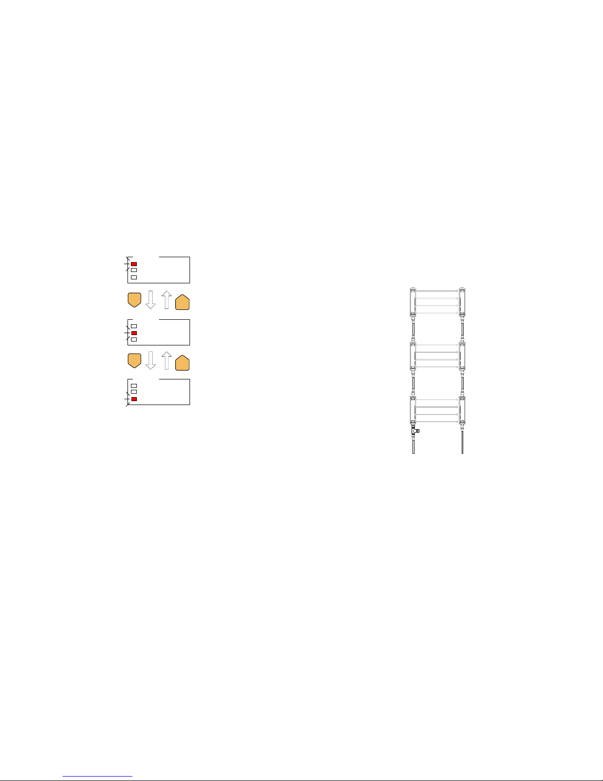
When series connected, the closest sensor to the extension cable
becomes 1CH and the second closest becomes 2CH.
Channel Numbers in Series Connection
3CH
2CH
1CH
Page 11
- 13 -
Changing selected channel
when connected to three sensors
+
|
CH(+)CH(-)
+
|
CH(+)CH(-)
+
|
CH(+)CH(-)
1ch is selected
(After power on)
2ch is selected
3ch is selected
1ch is selected
The indicator will be displayed as illustrated below, depending on which
function is to be set. This indicates that a setting item is to be
proceeded to all the sensors.
CAUTION
If the channel is changed while making a setting, content of the setting
will be cancelled.
- 14 -
8 MONITOR/SET
CAUTION
After the changing the setting of the sensor, a start-up check must
be conducted. Normal operation can only be allowed after safety is
confirmed.
A change of the setting can only be done under observance of laws/
standards which are related to safe operation of the product.
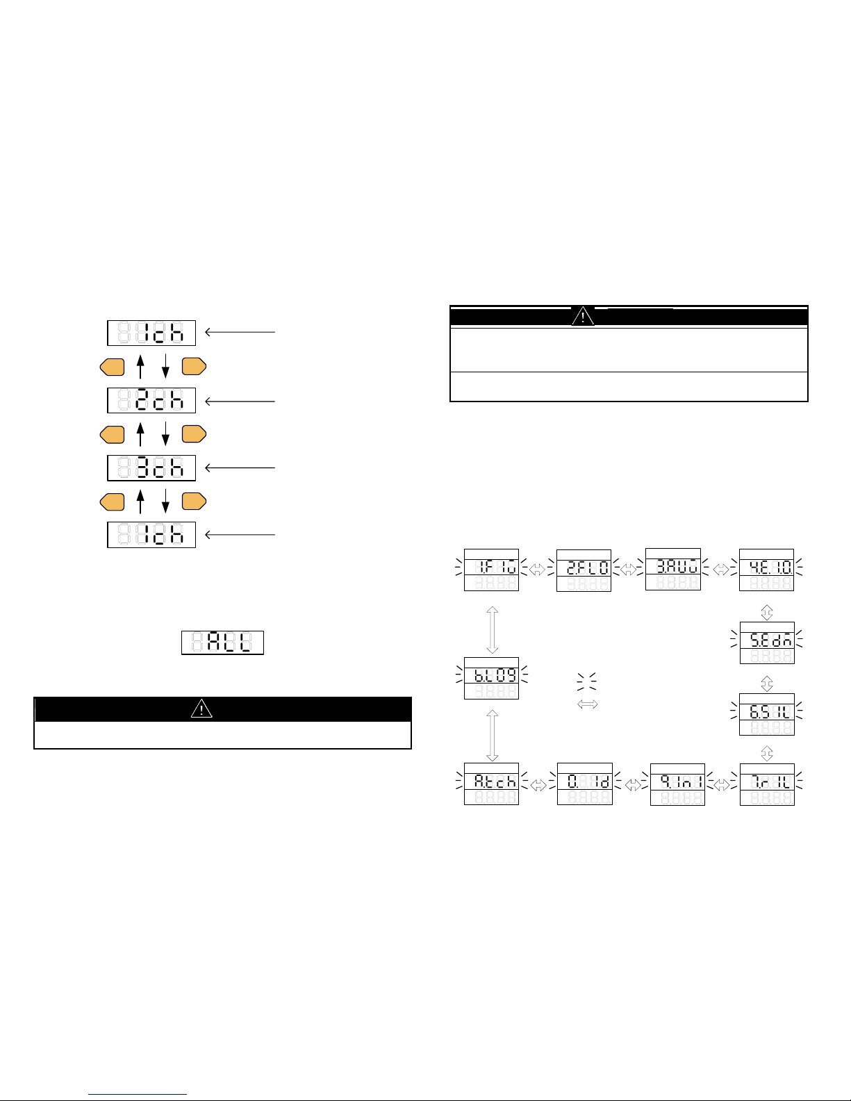
This function enables the monitoring of current set values and functions
of the sensor. When a set value is changed, content of the change is
reflected on sensor. The value which is indicated first in each category
is the current set value.
The method of change into each mode is as illustrated below.
By pressing [ENTER] key when the selected function is displayed,
editing of selected function becomes possible.
(i)F3SN
1.Fixed blanking
2.Floating blanking
4.Ext. indicator output
3.Auxiliary output
5.Ext. device monitor
9.initialize
0.ID
7.Restart in terlock
6.Start interlock
1.FIX
2.FLO
3.AUX 4.E.I.O.
5.EDM
6.SIL
7.RIL9.INI0.ID
[UP][DOWN]Key
Blinking
A.Threshold teach
A.TCH
B.Error log view
B.LOG
Page 12

- 15 -
(ii)F3SH
3.Auxiliary output
9.Initialize
0.ID
7.Restart interlo ck
6.Start interlock
3.AUX
4.E.I.O.
4.Ext. indicator output
5.Ext. device monitor
5.EDM
6.SIL
7.RIL
9.INI0.ID
A.Threshold teach
A.TCH
B.Error log view
B.LOG
(iii)F3ZN
1.Fixed blanking 3.Output #2
8.Threshold
2.Floating blanking
4.Ext. indicator output
9.Initialized
0.ID
9.INI0.ID
1.FIX 2.FLO
3.OU2
4.E.I.O.
8.TH
B.Error log view
0.LOG
<Common Note for MONITOR/SET function>
1. Edited value will not become active if NOT “SEND” to sensor, nor
“Function Valid (1.Fun-on)” is not selected.
2. “Loc” may display if “Setting lock” or “Setting limitation” has been
set. See clause10.1 and 10.3.
3. Please do not drop a power supply on the "Send" display after
pushing the [ENTER] key before being displayed as "Good." When
a power supply should be dropped, a sensor may not carry out
normal operation.
- 16 -
8.1 Fixed blanking
<F3SN, F3ZN>
CAUTION
In order prevent access to a dangerous area, fixed barrier guards
must be placed in fixed blanked areas.
Failure to do so may result in serious injury.
When Floating blanking function is enabled simultaneously, the
beam more than a plan may become invalid.
Please perform sufficient verification, when you confirm both
functions simultaneously.
Failure to do so may result in serious injury.
Fixed blanking function partly voids detection zone of sensor. Entrance
of object into invalid detection zone does not change output status.
There are two ways to choose which zone is to be blanked.
1. Teaching: Blocked beams are set as beams for blanking. Error will
be displayed if there are no blocked beams.
2. Manual: Select beam number first, and then choose
blanked/not blanked for each selected beam. Beams are
numbered as below figure.
7
6
5
4
3
2
1
Page 13

- 17 -
<Surveillance mode>
F3SN can set up the following operation in consideration of safety.
1. Setting release at the light receiving condition
In case a blanked beam becomes clear, F3SN will automatically
invalids fixed blanking function. In other words, no blanked beam
will exist. Reset of power makes previous fixed blanking setting
active.
2. Lockout mode at the light receiving condition
In case a blanked beam becomes clear, F3SN will become lockout
condition. Reset of power, or Reset input makes previous fixed
blanking setting active.
Make sure to make blanked areas so that no one can reach to the
dangerous part from blanked areas. All blanked beams need to be
blocked by object.
The above functions are only implemented on F3SN, where safety is
necessary. For F3ZN, fixed blanking function continues even if blanked
beam becomes clear.
<Note>
Models produced before April 2002 can not use setting of "Surveillance
mode". Sensors which has specific serial number also can not use the
setting. (If the surveillance mode is set to above model, "setting release
at the light receiving" is always set.) Please confirm at the time of a
setup.
- 18 -
<F3SN>
Go to ②-2
001:Select beam num.
①
z
②-1 ②-2 ②-3
②-4
Go to ①
after 1 sec.
Go to ②-4
after 1 sec
Fixed blanking
Error
Function Valid
Beam select (manual)
Beam select (manual)
Beam select (manual)
Setting completed
Function Valid
Beam select (Teach)
Beam select (Teach)
Send to sensor
ON:Valid
OFF:Invalid
ON:Beam selected
OFF:Beam un-selected
ENT:Beam(s) selected
Go to ②-3
after 1 sec
CLR:Clear selected
beam(s)
When "teached", blocked
beams are selected.
Note: When "Enter" key
pressed with no blocked
beams, "Err" is displayed.
OR
OR
Blinking
[Cancel] Key
[Enter] Key
[Up][Down] Key
1.FIX
②-1-1
1.FUN 2.TCH
②-2-1
3.MAN
②-3-1 ②-4-1
SEND
②-2-2
GOOD
ERR
②-3-2
GOOD
ERR
②-3-3
GOOD
ERR
②-5
Surveillance mode
Go to ②-5
Surveillance mode
Lockout mode at the
light receiving condition
Setting release at the
light receiving condition
3.MON
Page 14

- 19 -
<F3SN, F3ZN>
About F3SN, it becomes the following displays by the serial number.
Go to ②-2
001:Select beam num.
①
z
②-1 ②-2 ②-3 ②-4
Go to ①
after 1 sec.
Go to ②-4
after 1 sec
Fixed blanking
Error
Function Valid
Beam select (manual)
Beam select (manual)
Beam select (manual)
Setting completed
Function Valid
Beam select (Teach)
Beam select (Teach)
Send to sensor
ON:Valid
OFF:Invalid
ON:Beam selected
OFF:Beam un-selected
ENT:Beam(s) selected
Go to ②-3
after 1 sec
CLR:Clear selected
beam(s)
When "teached", block ed
beams are selected.
Note: When "Enter" key
pressed with no blocke d
beams, "Err" is dis played.
OR
OR
Blinking
[Cancel] Key
[Enter] Key
[Up][Down] Key
1.FIX
②-1-1
1.FUN 2.TCH
②-2-1
3.MAN
②-3-1 ②-4-1
SEND
②-2-2
GOOD
ERR
②-3-2
GOOD
ERR
②-3-3
GOOD
ERR
- 20 -
Example of how to set fixed blanking.
Example1:Set Fixed Blanking using "teaching"
②-1-1:Select "1.Fun-on"(Function valid)
Place an object where you want to be "blanked"
②-2-1:Select "2.tch-Ent"(Beams select)
②-4:Send setting to sensor
Setting completed
[good] displayed
ONE POINT:
After setting has complete d, you can confirm the
blanked beam numbers by using ②-3:Manual Beam
select menu.
[good] displayed
[Err] displayed・・・Object is not mounted properly.
Replace it and try ②-2 again.
[Err] displayed・・・Couldn't send setting to sensor.
Check wiring, etc. and try a gain from the beginning
Example2:Set Fixed Blanking using "manual"
②-1-1:Select "1.Fun-on"(Function valid)
②-3:Select "3.man"(manual beam select)
②-3-1:Input beam number to be "blanked"
②-3-2:Select "on"(beam selected)
②-4:Send setting to sensor
Setting completed
[good] displayed
[good] displayed
In order to "blank" more than one beam, repeat
Select beam number -> select "on" -> [CANCEL] Key
command, and push [ENTER] key at the end.
[Err] displayed・・・Couldn't send setting to sensor.
Check wiring, etc. and try again from the beginning
[Err] displayed・・・Wrong beam number was inputted.
Input correct number and try again .
Page 15

- 21 -
8.2 Floating blanking
<F3SN, F3ZN>
CAUTION
Use of floating blanking function involves a change of the safety
distance. Always recalculate and re-measure the safety distance to
confirm that it meets the applicable standards, after the change.
Failure to do so may cause the machine to fail to stop before an operator
reaches a dangerous area, and may result in serious injury.
When Fixed blanking function is enabled simultaneously with floating
blanking function, more beams than your plan may become invalid.
Perform sufficient verification, when you use both functions
simultaneously.
Failure to do so may result in serious injury.
Floating blanking function allows the output to remain ON when beams
of the sensor are interrupted anywhere in the field. In contrast with fixed
blanking function, which invalids fixed detection area, floating blanking
function ignores object smaller than specified radius.
Floating can be set for 1 to 3 floating beams.
(When 1 floating beam is set, sensor will turn OFF when 2 or more
beams are blocked).
- 22 -
CAUTION
Use of floating blanking function involves a change of the safety
distance. Always recalculate and re-measure the safety distance to
confirm that it meets the applicable standards, after the change.
Failure to do so may cause the machine to fail to stop before an operator
reaches a dangerous area, and may result in serious injury.
Resolution
(mm)
Undetectable
dia.(mm)
Floating beam
Beam gap(mm)
0 1 2 3 1 2 3
9 14 23 32 41 4 13 22
15 25 40 55 70 5 20 35
30 40 70 100 130 20 50 80
60 70 130 190 250 50 110 170
The following modes can be set in floating blanking function;
1. Sequential beam mode
- ON: Output becomes OFF when consecutive blocked beams
exceeds floating beams. Output will not becomes OFF
when plural objects smaller than undetectable diameter
exist.
- OFF: Output becomes OFF when sum of blocked beams exceeds
floating beams. Output may becomes OFF when plural
objects smaller than undetectable diameter exist.
2. Outermost beam invalid mode
Outermost beam invalid mode excludes outermost beams from
floating blanking.
When this mode is valid, the output will turn OFF if one of the
outermost beams is blocked, even if floating blanking is active.
Page 16

- 23 -
①
②-1 ②-2 ②-3 ②-4 ②-5
Go to ②-3
Go to ②-4
Go to ②-5
Floating blanking
Sequential modeFunction Valid Floating beam no.
Outermost beam invalid
Function valid Floating beam no. Sequential mode
Outermost beam invalid
Send to sensor
Setting completed
Error
Blinking
[Cancel] Key
[Enter] Key
[Up][Down] Key
1:1 floating beam
Go to ①
after 1 sec.
2:2 floating beams
3:3 floating beams
CLR: floating beams
clear
2.FLO
1.FUN
②-1-1
2. NO. 3.SEQ 4.O.B.I. SEND
②-2-1 ②-3-1 ②-4-1 ②-5-1
Go to ②-2
ON:Valid
OFF:Invalid
ON:Valid
OFF:Invalid
ON:Valid
OFF:Invalid
GOOD
ERR
- 24 -
8.3 Auxiliary output
<F3SN, F3SH>
This is a non-safety related output used to display a status.
This output cannot be used for the purpose of safety.
This can be selected to the following output;
1. Dark ON
2. Light ON
3. Light diagnosis
4. Lockout
5. Outermost beam monitoring
6. Blanking monitoring
7. Specified beam
For detail of each output, please refer to ANNEX1 INDEX.
<Note>
Because F3SH does not have fixed blanking function, “6. Blanking
monitoring” is not selectable.
8.4 Output2
<F3ZN>
This is a output of F3ZN used to display a status.
Available signals are the same as 8.3 Auxiliary output.
Page 17

- 25 -
③-2
①
Auxiliary output
Setting completed
Error
Send to sensor
②-7
Specified beam
②-6
Blanking monitor
②-5
Outermost beam monitor
②-4
Lockout
②-3
Light diagnosis
②-2
Light ON
②-1
Dark ON
Beam select (Teach)
③-1(from ②-7)
OR
ENT:Beam(s) selected
CLR:Clear selected
beam(s)
Go to ③-2
after 1 sec.
(Only when ②-7 is
selected, go to ③-1)
Blinking
[Cancel] Key
[Enter] Key
[Up][Down] Key
Go to ①
after 1 sec.
When "teached", blocked
beams are selected.
Note: When "Enter" key
pressed with no blocked
beams, "Err" is displayed.
3.AUX
1.D.ON 2.L.ON 3.L.DG 4.L.OU
5.O.B.M.6.BLN7.SPC
③-1-1
GOOD
ERR
SEND
③-2-1
GOOD
ERR
- 26 -
③-2
①
Setting completed
Error
Send to sensor
②-7
Specified beam
②-6
Blanking monitor
②-5
Outermost beam m onitor
②-4
Lockout
②-3
Light diagnosis
②-2
Light ON
②-1
Dark ON
Beam select (Teach)
③-1(from ②-7)
OR
ENT:Beam(s) selected
CLR:Clear selected
beam(s)
Go to ③-2
after 1 sec.
(Only when ②-7 is
selected, go to ③-1)
Blinking
[Cancel] Key
[Enter] Key
[Up][Down] Key
Go to ①
after 1 sec.
When "teached", blocked
beams are selected.
Note: When "Enter " key
pressed with no blocked
beams, "Err" is displayed.
1.D.ON 2.L.ON 3.L.DG 4.L.OU
5.O.B.M.6.BLN7.SPC
③-1-1
GOOD
ERR
SEND
③-2-1
GOOD
ERR
Output #2
3.OU2
Page 18

- 27 -
8.5 External indicator output
<F3SN, F3SH F3ZN>
This is a non-safety related output which can be connected to an
optional indicator, such as F39-A01P-.
Applicable only to the models which can be connected in series.
This can be selected to the following output;
1. Dark ON
2. Light ON
3. Light diagnosis
4. Lockout
5. Test input-ON
6. Test input-OFF
7. Blanking setting
For detail of each output, please refer to ANNEX1 INDEX.
<Lighting pattern setup>
Display Lighting pattern setup
LIHt Light
bln.1 It blinks in a cycle of 0.5 seconds.
bln.2 It blinks in a cycle of 1 seconds.
bln.3 It blinks in a cycle of 2 seconds.
<Note>
1. F3ZN can set up only 1-4.
2. There are some which cannot set up above 5-7 by the serial
number about F3SN and F3SH.
3. There are some which cannot set up a blink pattern by the serial
number. (Light only)
4. Because F3SH does not have fixed blanking function, “7.
Blanking setting” is not selectable.
- 28 -
<F3SN, F3SH>
⑤-1
①
Setting completed
Error
Send to sensor
②-4
Lockout
②-3
Light diagnosis
②-2
Light ON
②-1
Dark ON
Blinking
[Cancel] Key
[Enter] Key
[Up][Down] Key
Go to ①
after 1 sec.
1.D.ON 2.L.ON 3.L.DG 4.L.OU
SEND
⑤-2
GOOD
ERR
Ext. indicator output
4.E.I.O.
②-6 ②-5
Test input-ON
Test input-OFF
7.b.L.S
6.t.OF
5.t.on
④-1
Lighting pattern setup
LIHt
bLn.1
bLn.2
bLn.3
②-7
Blanking setting
③
Lighting pattern setup
FLSH
Page 19

- 29 -
<F3SN, F3SH, F3ZN>
About F3SN and F3SH, it becomes the following displays by the serial
number.
③-1
①
Setting completed
Error
Send to sensor
②-4
Lockout
②-3
Light diagnosis
②-2
Light ON
②-1
Dark ON
Blinking
[Cancel] Key
[Enter] Key
[Up][Down] Key
Go to ①
after 1 sec.
1.D.ON 2.L.ON 3.L.DG 4.L.OU
SEND
③-2
GOOD
ERR
Ext. indicator output
4.E.I.O.
- 30 -
8.6 External device monitoring
<F3SN, F3SH>
This function can detect malfunction of external device which controls
hazardous area of machine. (e.g. contact welding)
The determination time can be set in respect to the response time of
relay being used. The setting time must be between 100ms to 600ms
and can be set in 5ms increments.
①
②-1
Go to ②-2
Change delay time
using [UP][DOWN]
[L][R]keys.
(100 to 600 ms;
every 5ms)
②-2
Go to ②-3
②-3
Ext. device monitor
Function valid
Acceptable delay time
Send to senso r
Function valid
Error
Setting completedSelect time (ms)
Blinking
[Cancel] Key
[Enter] Key
[Up][Down] Key
Go to ①
after 1 sec.
5.EDM
②-1-1 ②-2-1
②-3-1
1.FUN 2.TIM SEND
ON:Valid
OFF:Invalid
300
GOOD
ERR
Page 20

- 31 -
8.7 Start interlock
<F3SN, F3SH>
When this function is ON, the outputs remain in the OFF-state (i.e.
interlock state) after power ON. Interlock state can be released by a
manual reset when there are no obstructions in the detection zone.
CAUTION
This function is valid only when using manual reset mode. When in
auto reset mode, the start interlock function is automatically
disabled.
②-1
②-2
Start interlock
Setting completed
Error
Function Valid
Function Valid Send to sensor
Blinking
[Cancel] Key
[Enter] Key
[Up][Down] Key
Go to ①
after 1 sec.
①
6.SIL
1.FUN SEND
②-1-1
②-2-1
GOOD
ERR
Go to ②-2
ON:Valid
OFF:Invalid
- 32 -
8.8 Restart interlock
<F3SN, F3SH>
When this function is ON, the outputs remain in their OFF-state (i.e.
interlock state) when sensor is interrupted. Interlock state can be
released by a manual reset when there are no obstructions in the
detection zone.
CAUTION
This function is valid only when using manual reset mode. When in
auto reset mode, the start interlock function is automatically
disabled.
②-1
②-2
Setting completed
Error
Function Valid
Function Valid Send to sensor
Blinking
[Cancel] Key
[Enter] Key
[Up][Down] Key
Go to ①
after 1 sec.
①
1.FUN SEND
②-1-1
②-2-1
GOOD
ERR
Go to ②-2
ON:Valid
OFF:Invalid
Restart interlock
7.RIL
Page 21

- 33 -
8.9 Threshold adjustment
<F3ZN>
This function enables to adjust threshold value of F3ZN.
Upper row displays current minimum light level (minimum value
throughout all beams in the sensor), and lower row displays current
threshold value.
Threshold value of the sensor can be adjusted between 18 (the default
value at shipment from factory) and 100.
Current minimum light level
Threshold value.
Change this valud using
[UP][DOWN] [L][R] keys.
(18 to 100)
Threshold adjustment
Threshold adjustment
Setting completed Error
Send to sensor
Blinking
[Cancel] Key
[Enter] Key
[Up][Down] Key
Go to ①
after 1 sec.
8. TH
①
②
③
18
SEND GOOD ERR
- 34 -
8.10 Setting initialization
<F3SN, F3SH, F3ZN>
This function returns the sensor setting to their default value.
Default value of each function
Function F3SN F3SH F3ZN
Fixed blanking Invalid – Invalid
Floating blanking Invalid – Invalid
Auxiliary output / Output2 Dark ON
External indicator output Light ON
External device monitoring Valid –
Start interlock Valid –
Restart interlock Valid –
Threshold value – – 18
<Note>
ID setting will not be changed by Initialization Setting.
Initialization
Initialization Send to sensor
Setting completed Error
Blinking
[Cancel] Key
[Enter] Key
[Up][Down] Key
Go to ①
after 1 sec.
CANC:Cancel SEND
Go to ①
①
9.INI
②-1 ②-2
②-3
GOOD ERR
Page 22

- 35 -
8.11 ID setting
<F3SN, F3SH, F3ZN>
ID number can be set specific to each sensor.
The possible setting number range is between 0000 and 9999.
(Default will be 0000)
ID Setting
ID Setting Send to sensor
Setting completed Error
Blinking
[Cancel] Key
[Enter] Key
[Up][Down] Key
Change ID valud using
[UP][DOWN] [L][R] keys.
(0000 to 9999)
Go to ①
after 1 sec.
①
②
0. ID
0000 SEND
GOOD ERR
- 36 -
8.12 Threshold teach
<F3SN, F3SH>
This function can be used to display receiving light level of sensor or
adjust ON-threshold level to most suitable value. So, it makes possible
to shorten the detection distance depending on the installation condition.
This function is effective in preventing mutual interference and external
light interference.
Threshold teach function consists of three steps of following.
1. Display for receiving light level value.
2. Calculate the optimal value of ON threshold level and adjust
manually.
3. Write ON-threshold level into sensor.
CAUTION
Perform this function at the condition that all the beams of a sensor are
incident state. The sensor cannot be set correctly when any beams are
blocked.
1. Display for receiving light level value
This function displays receiving light level value of sensor.
It has three kinds of display modes of receiving light level as follows.
Min-Max light level display mode
Maximum value and minimum value in receiving light levels of all
beams are displayed. The maximum value is displayed on the top
row in the display. The minimum value is displayed with the
approximate beam position having the minimum value on the
bottom row in the display.
Individual light level display mode
The receiving light level of the selected beam is displayed.
The beam number is displayed on the top row. The receiving light
level corresponding to the beam number is displayed on the
bottom row.
Page 23

- 37 -
Individual max light level display mode
The maximum receiving light level of the selected beam is
displayed.
The beam number is displayed on the top row. The maximum
receiving light level corresponding to the beam number is
displayed on the bottom row.
Threshold teach
TCH
(1)
(2)-1
P.123
Max-Min Level
Go to
2. threshold
calculate.
(2)-2
Individual Level
U/D
Individual Level
A.123
A.122
L/R
Individual Max. Level
L/R
(2)-3
L.123
Individual Max. Level
U/D
L.122
L/R
U/D
ENTER Key
CANCEL Key
[L]/[R] Key
[UP]/[DOWN] Key
Beam number is
changed
Beam number is
changed
Go to (1)
Go to
2. threshold calculate.
Go to (1)
Go to
2. threshold calculate.
The fourth figure of the bottom row indicator of “(2)-1” indicates that
the approximate beam position having the minimum light level.
The beam positions of the sensor are divided in to three groups, top,
middle, and bottom, and displayed as show in the figure below. (The
bottom position means the side with power supply lines.)
Max-Min Level
Lower position:
Top
Lower position:
Middle
Lower position:
Bottom
- 38 -
2. Calculate the optimal value of ON threshold level and adjust
manually.
The sensor automatically calculates the optimal value of
ON-threshold on the basis of the minimum light level. After automatic
calculation is completed, “Good” is displayed on top row and the
calculated ON-threshold is displayed on bottom row.
Additionally, the displayed ON-threshold value can be adjusted
manually. ON-threshold can adjust in the range of 18 to 100.
NOW CALC
ON-threshold calculate
(1)
Good 20
(2)
Adjustment of ON-threshold
Calculate
complete
U/D
Good 19
(2)-1
Adjustment of ON-threshold
Manual adjustment of
ON-threshold
Go to 1. Display for receiving
light level value No.(2)-1
Go to 3. ON-threshold
write in to sensor
ENTER
CANCEL
One-point advice:
A
djust beams of the sensor with this function so that the
minimum receiving light level becomes higher. By doing this, the
sensor detects stably.
Page 24

- 39 -
3. Writing ON-threshold level into sensor.
ON threshold level obtained by calculation is written in a sensor.
When the writing is failed, check connecting condition between the
sensor and the F39-MC11 and start from the first.
A.TCH SEND
Threshold write
(1)
Go to 1. display for receiving
light level value No. (2)-1.
ENTER
A.TCH Good
Threshold write
A.TCH ERR
Threshold write
Write-in success Write-in failure
After 1
second.
Go to 1. display
for receiving light
level value No.
(1).
- 40 -
8.13 Error log view
<F3SN, F3SH, F3ZN>
The error log recorded in sensor is displayed.
The error log is written with error codes. See the contents of error code
at “ANNEX3 ERROR CODE LIST” (Page 60 ) for detailed information.
The error code having smaller error number is newer error.
d1.35
Error Log View
Error Log View
b.Log
(1)
CH
U/D
Error Log View
d2.21
L/R
Change emitter / receiver
Change sensor channel
(2) (3)
(5)(4)
Error Log View
Error Log View
L1.61
d1.21
Change Error number
L/R
U/D
ENTER Key
CANCEL Key
[L]/[R] Key
[UP]/[DOWN] Key
CH
CH Key
Error Code
Error Number
L :Emitter
D :Receiver
Page 25

- 41 -
9 COPY
This function allows you to copy settings of one sensor and transfer
them to another sensor. The settings which can be changed in
Monitor/Set mode, will be copied. (Including ID)
Inside the F39-MC are banks of the memory to store the date of sensor.
The data will not be deleted in case of power OFF since the data in the
bank is stored in EEPROM.
Bank lock setting protects data from being deleted by mistake.
The numbers of banks are listed below. Each bank can store setting
data of one sensor.
F3SN : 1
F3SH : 1
F3ZN : 9
<Note>
1. Banks will be allocated independently to sensor models (F3SN/F3SH
/F3ZN). Copying to a sensor with different model is not possible. For
example, copying from F3SN to F3ZN is not possible.
2. Copying to sensor with different detection capability (or beam gap) is
not possible.
Switch modes are illustrated below;
Section9.1(42page) Section9.2(43page) Section9.3(44page)
1.Upload
2.Download
3.Bank Lock
1.U.LD 2.D.LD 3.B.LC
[UP][DOWN]KeyBlinking
- 42 -
9.1 Upload (Copy Sensor data to F39-MC)
Copy the setting data of one sensor to the bank of F39-MC.
Select <1.U.Ld> and press [ENTER] key. Bank from 1 to 9 can be
changed with using [UP][DOWN] keys (F3ZN only).
The illustration below shows that setting data from the sensor is stored
into bank 1 of F39-MC.
Select bank number using
[UP][DOWN] keys.
Note: F3SN/F3SH has only
Bank1
Upload
Upload Setting completed Error
Blinking
[Cancel] Key
[Enter] Key
1.U.LD
①
②
BK 1:Bank #1 GOOD ERR
Go to ①
after 1 sec.
③
<Note>
Bank 1 for F3SN, F3SH and F3ZN are stored in different memories.
Page 26

- 43 -
9.2 Download (Copy F39-MC data to Sensor)
WARNING
After the changing the setting of the sensor, a start-up check must
be conducted. Normal operation can only be allowed after safety is
confirmed.
A change of the setting can only be done under observance of laws/
standards which are related to safe operation of the product.
Copy the setting data of one sensor stored in the bank of F39-MC to
another sensor.
<Note>
1. Banks will be allocated independently to sensor models
(F3SN/F3SH/F3ZN). Copying to sensor with different model is not
possible. For example, copying from F3SN to F3ZN is not possible.
2. Copying to sensor with different detection capability (or beam gap) is
not possible.
3. Please do not drop a power supply on the "bk 1" display after
pushing the [ENTER] key before being displayed as "Good." When a
power supply should be dropped, a sensor may not carry out normal
operation.
Download
Download Setting completed Error
Select bank number using
[UP][DOWN] keys.
Note: F3SN/F3SH has only
Bank1
Blinking
[Cancel] Key
[Enter] Key
①
②
2.D.LD
BK 1:Bank #1 GOOD ERR
Go to ①
after 1 sec.
③
- 44 -
9.3 Bank Lock (Prohibit overwriting to bank data)
To prohibit overwriting to a bank that has been stored with the setting
data of the sensor, select this function by following means;
Select <3.b.Lc>, then press [ENTER] key to enter Bank lock mode.
Select the bank with [UP][DOWN] keys and set to either prohibit writing
<Loc> or permit writing <FrEE> with [ENTER] key.
Bank lock
Bank lock
Bank lock
Bank lock
Blinking
[Cancel] Key
[Enter] Key
[Up][Down] Key
LOC:Overwrite
disabled
FREE:Overwrite
enabled
3.B.LC
①
②-1
BK 1:Bank #1 BK 2:Bank #2
②-2
Selectable from BK2 to BK9
(Only F3ZN)
④-1
Setting completed
GOOD
Go to ②
after 1 sec
③-1
<Note>
The Locked bank cannot be selected when uploading the setting data.
(The bank is not displayed.)
Page 27

- 45 -
10 PROTECT
WARNING
F39-MC must be managed and used only by qualified persons.
Operation by un-qualified persons could create a hazardous
condition which may lead to a loss of safety function.
This mode enables the lock function which disallows setting changes
without a password, setting limitations can also be set to restrict the
changes that can be made.
<Note>
This function resides with the F39-MC and not the sensor. If the
F39-MC is not protected, it could enable un-authorized persons to
change the setting of the sensors.
We strongly recommend, to set “Protect” to all purchased F39-MCs.
Switching modes is illustrated below;
Section10.1(46page) Section10.2(47page) Section10.3(48page)
[UP][DOWN]KeyBlinking
1.Setting lock
3.Setting limitation
2.Change password
1.S.LC 2.PAS 3.LMT
- 46 -
10.1 Setting lock
Prohibit setting change. Select from [Lock all sensors], [Lock only
F3SN+F3SH], [Lock only F3ZN] or [Unlock all sensors].
A password (4 digit number) is required to change locked status.
When locked, the following is prohibited;
-Sending to sensor in Set/Monitor function
-Download to sensor in Copy function
Enter password except current
setting is "Unlock".
Setting lock
Setting lock
Enter password
Setting completed
RST:Unlock all
sensors
ALL:Lock all
sensors
SN.SH:Lock F3SN &
F3SH
ZN:Lock only
F3ZN
Enter 4 digit number (0000 to 9999)
ERR:Password
unmatched
OR
Blinking
[Cancel] Key
[Enter] Key
[Up][Down] Key
①
1.S.LC
②
③
④
0000
GOOD
Go to ①
after 1 sec
Page 28

- 47 -
10.2 Change password
Change password (4 digit number) to release setting lock.
The default value is “0000”.
Change password
Enter old password
Password change
Enter new password
Blinking
[Cancel] Key
[Enter] Key
Enter 4 digit number (0000 to 9999)
"ERR" is displayed if password unmatched
Enter 4 digit number (0000 to 9999)
①
2.PAS
②
OLD
③
NEW
④
GOOD
Go to ①
after 1 sec
<Usage>
We strongly recommend to use with password other than “0000”, and
with Setting lock function. This will prevent unauthorized setting
change by un-qualified person.
<Note >
Please remember changed password.
If you forget, please contact OMRON.
- 48 -
10.3 Setting limitation
Limit the re-settable functions in order to prevent hazardous setting by
mistake.
The following can be set;
・Maximum fixed blanking zones (0 to 3 zones)
・Maximum fixed blanking beams (1 to 9 beams)
・Maximum floating blanking beams (0 to 3 beams)
The value which exceeds above set value, cannot be set to the sensor.
<How to use>
Set limitation beforehand.
This prevents hazardous settings caused by mistake.
<Description>
“Fixed blanking zone” means is number of set of beam(s) that can be
blanked.
<Note >
This function does not protect against “COPY” function. (Only
protected against MONITOR/SET function).
Page 29

- 49 -
①
②-1 ②-2 ②-3
Setting limitation
No.of fixed zones No.of fixed beams No.of floating beams
No.of fixed zones No.of fixed beams
No.of floating be ams
2: 2 zones
3: 3 zones
1: 1 zone
0: 0 zone (disabled)
1: 1 beam
2: 2 beams
9: 9 beams
0: 0 beam (disabled)
Setting completed
Setting completed Setting completed
③-1 ③-2 ③-3
Go to ②-1
after 1 sec
・ ・ ・
3.LMT
1.X.FD 2.X.NO. 3.L.NO.
④-1 ④-2 ④-3
RST: Reset limitation
1: 1 beam
2: 2 beams
3: 3 beams
GOOD GOOD G OOD
Go to ②-2
after 1 sec
Go to ②-3
after 1 sec
RST: Reset limitationRST: Reset limitation
Blinking
[Cancel] Key
[Enter] Key
[Up][Down] Key
- 50 -
11 DISCONNECT F39-MC
After the setting has completed, be sure to disconnect cable and
F39-MC before normal use.
Operation procedure;
1. Disconnect F39-MC and cable from branching connector.
2. Attach connector cap to branching connector.
(Without the connector cap, water resistance cannot be maintained.)
CAUTION
Be sure that the machine power is OFF when disconnecting.
Disconnecting with the power ON may cause the F39-MC to
malfunction.
Connector Cap
Please set this to branching
connector when F39-MC is
not in use.
①
②
Page 30

- 51 -
12 MC11 ERROR CODES
“Err” may appear on the display indicating an error.
Please refer to the table below for detail of the
error codes.
Code Description of error Remedy
C001 Sensor Model error
Sensors with different model are
series connected.
Match all the sensor
models to be connected
in series.
C002 Sensor connection error
Communication error occurred
during connecting to sensor.
Confirm correct wiring.
C003 Communication error during
connection
Confirm that there are
no unloosen connector,
terminals or excessive
noise does not exists.
C004 EEPROM error
EEPROM data has been
corrupted.
Contact OMRON.
C005
and
others
F39-MC destructed Contact OMRON.
Error code
- 52 -
13 TROUBLESHOOTING
1. F39-MC is not powered ON.
Cause: 1.Cable or branching connector is not correctly mounted.
2. Capacity of power supply is not enough.
Remedy: 1.Mount correctly (see section 4)
2. Use power supply with enough capacity.
2. Communication connection indicator of F39-MC will not lit, or “not
conn” is displayed.
Cause: 1. F39-MC has powered on after sensor has powered on.
2. Plural F39-MC is connected, or F3ZP is connected.
Remedy: 1. Power on both F39-MC and sensor at same time.
2. Connect only one F39-MC to the sensor.
3. Test indicator and/or blanking indicator of sensor flashed or lit.
Cause: Normal condition. When communicating with F39-MC,
sensor becomes above condition.
Remedy: After setting completed, disconnect F39-MC and then
power on sensor.
4. “none” is displayed for bank number, when uploading.
Cause: Bank lock function is set for all banks.
Remedy: Unlock the bank. (see clause 9.3)
5. Unable to send to sensor; “Loc” is displayed
Cause: 1. Setting lock or 2. Setting limitation has been set.
Remedy: Unlock above function before sending. (See clause 10.1 or
10.3)
6. “Err” is displayed when teaching
Cause: Teaching is not completed with a blocked beam.
Remedy: Teach with one or more beams blocked.
Page 31

- 53 -
ANNEX1 INDEX
Terms Explanation
Auto reset mode
[F3SN, F3SH]
Interlock function is invalid in this mode. This mode can be
selected with wiring interlock selection input and reset input.
This mode voids all, despite the setting value of start/restart
interlock function.
A
Auxiliary output
[F3SN, F3SH]
Non-safety related output used to display a status.
This output cannot be used for the purpose of safety.
Blanking monitoring
output
(Auxiliary output, output2)
Output ON when the blanked beam becomes light
reception-state, when the fixed blanking function is valid.
B
Blanking setting
(Ext. indicator)
Output ON when fixed blanking function or floating blanking
function is effective.
D Dark ON
(Auxiliary output, output2,
Ext. indicator)
Output ON when sensor detects objects. In case series
connected, output ON when one or more sensors detects
objects.
External indicator output Non-safety related output which can be connected to an
optional indicator.
Applicable only to the models which can be connected in series.
E
External device
monitoring
[F3SN, F3SH]
This function can detect malfunction of external device which
controls hazardous area of machine. (e.g. contact welding)
Fixed blanking function [F3SN, F3ZN]
Partly voids detection zone of sensor. Entrance of object into
blanked detection zone does not change output condition.
F3SN: 1. Fixed blanking function becomes invalid when blanked
zone becomes clear, or lockout condition. Fixed
blanking function becomes valid again, after power has
reset.
2. It becomes lockout condition when blanked zone
becomes clear. Fixed blanking function becomes valid
again, after power has reset, or reset input.
F3ZN: Fixed blanking function is valid even after blanked zone
becomes light reception-state.
F
Floating blanking function [F3SN, F3ZN]
This function allows the output to remain ON when beams of
the sensor are interrupted anywhere in the field.
Floating can be set for 1 to 3 beams.
I ID Indicates numbers 0000 to 9999 which can be set specific to
each sensor.
L Light diagnosis
(Auxiliary output, output2,
Ext. indicator)
Output ON when unstable condition lasts for 3 seconds or
more.
Can detect deterioration of optical performance caused by dirty
optical surface, displacement of beams or deterioration of LED.
“Unstable condition” indicates that the light level remains within
+/-20% of threshold value.
- 54 -
Terms Explanation
Light ON
(Auxiliary output, output2,
Ext. indicator)
Output ON when detection area is clear. In case series
connected, output ON when all sensors’ detection area is clear.
Lockout output
(Auxiliary output, output2,
Ext. indicator)
Output ON when the sensor is in lockout condition (i.e. mode
which detects abnormality and stop the sensing function).
Lighting pattern setup The lighting pattern of external indicator is set up. A default is
"lighting." The blink cycle can set up 0.5 seconds, 1 second,
and 2 seconds.
Manual reset mode
[F3SN, F3SH]
Interlock function is valid in this mode.
This mode can be selected by wiring interlock selection input
and reset input.
Max. number of fixed
beams
(Protect)
Maximum number of beams which can be blanked by fixed
blanking function. Beams exceeding this number cannot be set
blanked.
Max. number of fixed
zones
(Protect)
Maximum number of set of beam(s) which can be blanked by
fixed blanking function.
One zone is defined as blanked beam(s) which is surrounded
by not-blanked beams.
M
Max. number of floating
beams
(Protect)
Maximum number of beams which can be set by floating
blanking function. Floating beams exceeding this number
cannot be set.
Outermost beam invalid
(Floating blanking)
This mode excludes outermost beams from floating blanking.
When this mode is valid, the output will turn OFF if one of the
outermost beams is blocked, even if floating blanking is active.
Outermost beam
monitoring output
(Auxiliary output, output2)
Output ON when only outermost beam(s) is/are interrupted.
O
Output2 [F3ZN]
Output of F3ZN used to display a status.
R Restart interlock function [F3SN, F3SH]
Outputs remain in the OFF-state (i.e. interlock state) when
sensor is interrupted. Interlock state can be released by a
manual reset when there are no obstructions in the detection
zone.
This function is valid only when using manual reset mode.
Sequential beam mode
(Floating blanking)
If this mode is valid, output becomes OFF when consecutive
blocked beams exceeds floating beams.
If this mode is invalid, output becomes OFF when sum of
blocked beams exceeds floating beams.
S
Specified Beam
(Auxiliary output, output2)
Output ON when any of specified beams are blocked.
When this signal is selected, it is necessary to specify beam.
Page 32

- 55 -
Terms Explanation
Start interlock function [F3SN, F3SH]
Outputs remain in the OFF-state (i.e. Interlock state) after power
ON. Interlock state can be released by a manual reset when
there are no obstructions in the detection zone.
This function is valid only when using manual reset mode.
Surveillance mode
(Fixed blanking)
It is the function which supervises whether a blanked beam
becomes clear. “setting release at the light receiving condition”
or “lockout mode at the light receiving condition” can be chosen.
Threshold teach It is the function which unites ON-threshold of a sensor with the
receiving light level value of a sensor, and is changed into the
optimal value.
Test input-ON
(Ext. indicator)
When a test input is ON, external indicator lights up. If a test
input turns ON, a sensor will operate an external diagnostic
function.
T
Test input-OFF
(Ext. indicator)
When a test input is OFF, external indicator lights up. If a test
input turns on, a sensor will operate an external diagnostic
function.
- 56 -
ANNEX2 FUNCTION LIST (according to sensor type)
F3SN
Function
Sensor
CH
Mode display
(Top row)
Mode display
(Bottom row)
ALL Function Valid / Invalid
Teach Teaching / Clear
Manual
Valid / Invalid (Set each beam)
1 to 3
Surveillance mode
(Note1)
Lockout mode at the light
receiving condition / Setting
release at the light receiving
condition
ALL
Fixed blanking
- Send to sensor
ALL Function Valid / Invalid
Floating Beam 1 / 2 / 3 / Clear
Sequential beam Valid / Invalid
1 to 3
Outermost beam invalid
Valid / Invalid
ALL
Floating blanking
- Send to sensor
Setting value L-on / D-on / Light diagnosis /
Lockout / Outermost beam /
Specified beam / Blanking
Auxiliary output
- Send to sensor
Setting value L-on / D-on / Light diagnosis /
Lockout / Test input-ON
(Note1) / Test input-OFF
(Note1) / Blanking setting
(Note1)
Lighting pattern setup
(Note1)
Light / Blink in a cycle of 0.5
seconds / Blink in a cycle of
1 seconds / Blink in a cycle
of 2 seconds
External indicator
output
- Send to sensor
Function Valid / Invalid
Setting time 100 to 600ms; every 5ms
External device
monitoring
- Send to sensor
Function Valid/Invalid Start interlock
- Send to sensor
Function Valid / Invalid Restart interlock
- Send to sensor
Initialization Cancel / Send to sensor
Setting value 0000 to 9999
ALL
ID setting
- Send to sensor
Receiving light level
value view
Receiving light level value
Adjusting threshold ON-threshold
1 to 3 Threshold teach
(Note 2)
- Send to sensor
SET/
MONITOR
1 to 3 Error log view Error log view Error code
1 to 3
Upload Bank number
1 to 3
Download Bank number
COPY
– Bank lock Bank number LOCK / FREE
Page 33

- 57 -
Lock object All / Only F3SN+F3SH / Only
F3ZN / Clear
– Setting lock
Input password Input 4 digit number
Old password Input 4 digit number – Change password
New password Input 4 digit number
No. of fixed
zones
Clear, 0 to 3
Max. no. of Fixed
beams
Clear, 1 to 9
PROTEC
T
– Setting limitation
Max. no. of
floating beams
Clear, 0 to 3
Note1: There are some which cannot be set up by the serial number.
See Group A of “1.2 Available function and Sensor serial number” (Page 3 )
Note2: There are some which cannot be set up by the serial number.
See Group B of “1.2 Available function and Sensor serial number” (Page 3 )
- 58 -
F3SH
Function
Sensor
CH
Mode display
(Top row)
Mode display
(Bottom row)
Setting value
L-on / D-on / Light diagnosis
/
Lockout / Outermost beam /
Specified beam
Auxiliary output
- Send to sensor
Setting value
L-on / D-on / Light diagnosis /
Lockout / Test input-ON /
Test input-OFF / Blanking
setting
Lighting pattern setup
(Note1)
Light / Blink in a cycle of 0.5
seconds / Blink in a cycle of
1 seconds / Blink in a cycle
of 2 seconds
External indicator
output
- Send to sensor
Function Valid / Invalid
Setting time 100 to 600ms; every 5ms
External device
monitoring
- Send to sensor
Function Valid / Invalid Start interlock
- Send to sensor
Function Valid / Invalid Restart interlock
- Send to sensor
Initialization Cancel / Send to sensor
Setting value 0000 to 9999
ALL
ID setting
- Send to sensor
Receiving light level
value view
Receiving light level value
Adjusting threshold ON-threshold
1 to 3 Threshold teach
(Note 2)
- Send to sensor
SET /
MONITOR
1 to 3 Error log view Error log view Error code
1 to 3
Upload Bank number
1 to 3
Download Bank number
COPY
– Bank lock Bank number LOCK / FREE
Lock object All / Only F3SN+F3SH /
Only F3ZN / Clear
– Setting lock
Input password Input 4 digit number
Old password Input 4 digit number – Change password
New password Input 4 digit number
No. of fixed zones Clear, 0 to 3
Max. no. of Fixed
beams
Clear, 1 to 9
PROTECT
– Setting limitation
Max. no. of floating
beams
Clear, 0 to 3
Note1: There are some which cannot be set up by the serial number.
See Group A of “1.2 Available function and Sensor serial number” (Page 3 )
Note2: There are some which cannot be set up by the serial number.
See Group B of “1.2 Available function and Sensor serial number” (Page 3 )
Page 34

- 59 -
F3ZN
Function
Sensor
CH
Mode display
(Top row)
Mode display
(Bottom row)
ALL Function Valid / Invalid
Teach Teaching / Clear 1 to 3
Manual
Valid / Invalid (Set each beam)
ALL
Fixed blanking
- Send to sensor
ALL Function Valid / Invalid
Floating Beam 1 / 2 / 3 / Clear
Sequential beam Valid / Invalid
1 to 3
Outermost beam invalid
Valid / Invalid
ALL
Floating blanking
- Send to sensor
Setting value L-on / D-on / Light diagnosis
/ Lockout / Outermost beam /
Specified beam / Blanking
Output2
- Send to sensor
Setting value L-on / D-on / Light diagnosis
/ Lockout
External indicator
output
- Send to sensor
Min. light level Threshold value
Threshold adjustment
- Send to sensor
Initialization Cancel / Send to sensor
Setting value 0000 to 9999
ALL
ID setting
- Send to sensor
SET/
MONITOR
1 to 3 Error log view Error log view Error code
1 to 3 Upload Bank number
1 to 3 Download Bank number
COPY
– Bank lock Bank number LOCK / FREE
Lock object All / Only F3SN+F3SH / Only
F3ZN / Clear
– Setting lock
Input password Input 4 digit number
Old password Input 4 digit number – Change password
New password Input 4 digit number
No. of fixed zones Clear, 0 to 3
Max. no. of Fixed
beams
Clear, 1 to 9
PROTECT
– Setting limitation
Max. no. of floating
beams
Clear, 0 to 3
- 60 -
ANNEX3 ERROR CODE LIST
Error code Contents and remedy
A8, AA Wiring error
Wiring is not performed correctly.
Please confirm a sensor instruction manual and check wiring.
A3 Error of the EDM function
Feed back signal is not returned to EDM line or a relay may be
welding.
Please improve wring or change a relay so that feed back signal is
returned correctly.
A7, 32 Communication error
The communication error has occurred by the wiring error, or a noise.
Please improve installation environment and wiring environment.
When you cannot solve, please contact our sales office.
35 to 38, 27 OSSD error
OSSD outputs are shorted together or OSSD output is shorted to
+24V line, 0V line, or the other I/O line or failure of OSSD output
circuit.
Please improve wiring. When you cannot solve, please contact our
sales office.
A2 Error by interference light
The sensor receives interference light from another sensor. Please
adjust an optical-axis including that of surrounding sensors. In
addition, please do interference light countermeasure as described in
sensor instruction manual.
A0, A1, A4, A5 Incorrect configuration on sensor connection
The model of emitter and receiver differs. When sensor is connected
in series, sensor connection is incorrect. Please check the sensor
model and connection status.
Other codes Internal error
Irreparable Error has occurred inside the sensor. Please contact our
sales office.
Page 35

- 61 -
ANNEX4 FUNCTION SETTING CARD
F3SN
FUNCTION SETTING VALUE
Function Valid/Invalid Fixed blanking
Blanked beam ________________ (List selected beams)
Function Valid/Invalid
Floating Beam 1/2/3/Clear
Sequential beam Valid/Invalid
Floating blanking
Outermost beam invalid Valid/Invalid
Auxiliary output Setting value L-on/D-on/Light diagnosis/ Lockout/
Outermost beam/ Specified beam/Blanking
Ext. indicator output Setting value L-on/D-on/Light diagnosis/ Lockout
Function Valid/Invalid External device
monitoring
Acceptable delay time ___________ms (100 to 600ms)
Start interlock Function Valid/Invalid
Restart interlock Function Valid/Invalid
ID setting Setting value ___________ (0000 to 9999)
F3SH
FUNCTION SETTING VALUE
Auxiliary output Setting value L-on/D-on/Light diagnosis/ Lockout/
Outermost beam/ Specified beam
Ext. indicator output Setting value L-on/D-on/Light diagnosis/ Lockout
Function Valid/Invalid External device
monitoring
Acceptable delay time ___________ms (100 to 600ms)
Start interlock Function Valid/Invalid
Restart interlock Function Valid/Invalid
ID setting Setting value ___________ (0000 to 9999)
F3ZN
FUNCTION SETTING VALUE
Function Valid/Invalid Fixed blanking
Blanked beam ________________ (List selected beams)
Function Valid/Invalid
Floating Beam 1/2/3/Clear
Sequential beam Valid/Invalid
Floating blanking
Outermost beam invalid Valid/Invalid
Output2
Setting value L-on/D-on/Light diagnosis/ Lockout/
Outermost beam/ Specified beam/Blanking
Ext. indicator output Setting value L-on/D-on/Light diagnosis/ Lockout
Threshold Adj. Setting value ___________ (18 to 100)
ID setting Setting value ___________ (0000 to 9999)
OMRON CORPORATION
Industrial Automa tion Company
Industrial Sensors Division
Sensing Devices and Components Division H.Q.
Shiokoji Horikawa, Shimogyo-ku, Kyoto, 600-8530 Japan
Tel:0120-919-066 (Free call)
OMRON ELECTRONICS LLC
After Sales Support Engineering Services Department
One Commerce Drive, Schaumburg, IL 60173-5302 U.S.A.
Phone: 1-847-843-7900 / Fax: 1-847-843-7787
OMRON CANADA INC.
Technical Sales and Services –Toronto
885 Milner Avenue, Scarborough, Ontario M1B 5V8
CANADA
Phone: 1-416-286-6465 / Fax: 1-416-286-6648
Technical Sales and Services -Montreal (French Language)
Phone: 1-514-636-6676 / Fax: 1-514-636-2959
EUROPEAN H.Q.
OMRON EUROPE B.V.
Wegalaan 67-69 P.O.BOX 13 2130AA Hoofddorp The
Netherlands
Phone: 31-23-56-81-300 / Fax: 31-23-56-81-388
AUSTRIA
OMRON Electronics G.m.b.H
Brunner Strasse 81,Box 323 A-1230 vienna
Phone: 43-1-801-90-0 / Fax: 43-1-804-48-46
BELGIUM
OMRON ELECTRONICS NV/SA
Stationsstraat 24 B-170 2 Groot-Bijgaarden Belgium
Phone: 32-2-4662-480 / Fax: 32-2-4660-687
CZECH
OMRON ELECTRONICS
spol.s.r.o.Srobarova 6 PRAHA 10 101 00 Czech Republic
Phone: 420-2-67-31-12-54, 420-2-71-73-13-19
Fax: 420-2-71-73-56-13
DENMARK
OMRON ELECTRONICS A/S
Odinsvej 15 DK-2600 GLOSTRUP Denmark
Phone: 45-43-44-00-11 / Fax: 45-43-44-02-11
FINLAND
OMRON ELECTRONICS OY
Mets-npojankuja 5 FIN-02130 ESPOO, Finland
Phone: 358-9-5495-800
Fax: 358-9-5495-8150, 358-9-5495-8155(CS)
FRANCE
OMRON ELECTRONICS S.a.r.l.
19,rue du Bois Galon 94121 FONTENAY SOUS BOIS
France
Phone: 33-1-49-74-70-00 / Fax: 33-1-48-76-09-30
GERMANY
OMRON ELECTRONICS G.m.b.H.
Elisabeth-Selbert-Strasse 17,40764
Langenfeld Germany
Phone: 49-2173-6800-0 / Fax: 49-2173-6800-400
HUNGARY
OMRON ELECTRONICS Kft.
H-1046 Budapest Kiss Erno u. 1-3. Hungary
Phone: 36-1-399-3050 / Fax: 36-1-399-3060
ITALY
OMRON ELECTRONICS S.r.l.
Viale Certosa, 49 20149 Milano- Italy
Phone: 39-02-32681 / Fax: 39-02-325154
NETHERLANDS
OMRON ELECTRONICS B.V.
Wegalaan 61 2132 JD Ho ofddorp. Postbus 582 2130 AN
Hoofddorp Netherlands
Phone: 31-23-5681100 / Fax: 31-23-5681188
中国
欧姆龍(中国)有限公司
中国北京西長安街 88 号 北京首都時代広場 1028 室 100031
Phone: 86-10 8391-3005 / Fax: 86-10-8391-3688
香港歐姆龍亞洲有限公司
香港九龍尖沙咀廣東道 25 号 港威大廈第2座 601-9 室
Phone: 852-2375-3827 / Fax: 852-2375-1475
台灣
台灣歐姆龍股 有限公司 總公司
台灣台北市復興北路 363 号 弘雅大楼6楼
Phone: 886-2-2715-3331 / Fax: 886-2-2712-6712
大韓民国
韓国OMRON株式会社
大韓民国 Seoul 市江南区新沙洞 618-3 New Seoul Bldg. 3階
Phone: 82-2-512-0871, 82-2-549-2766 (English/Japanese)
Fax: 82-2-517-9033
SINGAPORE
OMRON ASIA-PACIFIC PTE LTD
83 Clemenceau Avenue, #11-01 UE Square, Singarore
239920 Singapore
Phone: 65-6-835-3011 / Fax: 65-6-835-2711
AUSTRALIA
OMRON ELECTRONICS PTY. LTD.
71 Epping Road, North Ryde, Sydney NSW 2113 Australia
Phone: 61-02-9878-6377 / Fax: 61-02-9878-6981
INDONESIA
OMRON ASIA PACIFIC PTE. LTD.
INDONESIA REPRESENTATIVE OFFICE GRAHA
PRATAMA FLOOR3A, JL MT HARYONO KAV. 15, J AKARTA
12810 Indonesia
Phone: 62-21-8370-9555 / Fax: 62-21-8370-9550
MALAYSIA
OMRON ELECTRONICS SDN. BHD.
2.01, Level 2, Wisma Academy, 4A, Jalan 19/1, 46300
Petaling Jaya, Selangor Darul Ehsan, Malaysia
Phone: 603-79547323, 603-76250801 / Fax: 603-79546618
NEW ZEALAND
OMRON ELECTRONICS LIMITED.
65 Boston Road,Mt Eden Auckland New Zealand
Phone: 64-9-358-4400 / Fax: 64-9-358-4411
THAILAND
OMRON ELECTRONICS CO., LTD.
RASA TOWER 20TH FLOOR, #555 PHAHOLYOTHIN RD.,
CHATUCHAK, BANGKOK 10900 Thailand
Phone: 66-2-937-0500, CRM call center 66-2-942-6700
Fax: 66-2-937-0501
 Loading...