

Page 1

MicroHAWK F320-F / F330-F / F420-F / F430-F
Smart Camera
User Manual
Z433-E-01 (84-9000402-02)
Page 2

NOTE
• All rights reserved.
• No part of this publication may be reproduced, stored in a retrieval system, or transmitted, in any
form, or by any means, mechanical, electronic, photocopying, recording, or otherwise, without the
prior written permission of OMRON.
• No patent liability is assumed with respect to the use of the information contained herein. Moreover,
because OMRON is constantly striving to improve its high-quality products, the information con-
tained in this manual is subject to change without notice. Every precaution has been taken in the
preparation of this manual. Nevertheless, OMRON assumes no responsibility for errors or omis-
sions.
Neither is any liability assumed for damages resulting from the use of the information contained in
this publication.
Trademarks
• Sysmac and SYSMAC are trademarks or registered trademarks of OMRON Corporation in Japan
and other countries for OMRON factory automation products.
• Microsoft, Windows, Windows Vista, Excel, and Visual Basic are either registered trademarks or
trademarks of Microsoft Corporation in the United States and other countries.
• ODVA, CIP, CompoNet, DeviceNet, and EtherNet/IP are trademarks of ODVA.
• QR Code is a registered trademark of DENSO WAVE INCORPORATED.
Other company names and product names in this document are the trademarks or registered trade-
marks of their respective companies.
Copyrights
Microsoft product screen shots reprinted with permission from Microsoft Corporation.
Page 3

Terms and Conditions Agreement
Terms and Conditions Agreement
Warranty, Limitations of Liability
Warranties
Exclusive Warranty
Omron’s exclusive warranty is that the Products will be free from defects in materials and workmanship for a period of twelve months from the date of sale by Omron (or such other period expressed in
writing by Omron). Omron disclaims all other warranties, express or implied.
Limitations
OMRON MAKES NO WARRANTY OR REPRESENTATION, EXPRESS OR IMPLIED, ABOUT
NON-INFRINGEMENT, MERCHANTABILITY OR FITNESS FOR A PARTICULAR PURPOSE OF
THE PRODUCTS. BUYER ACKNOWLEDGES THAT IT ALONE HAS DETERMINED THAT THE
PRODUCTS WILL SUITABLY MEET THE REQUIREMENTS OF THEIR INTENDED USE.
Omron further disclaims all warranties and responsibility of any type for claims or expenses base
on infringement by the Products or otherwise of any intellectual property right.
d
Buyer Remedy
Omron’s sole obligation hereunder shall be, at Omron’s election, to (i) replace (in the form originally
shipped with Buyer responsible for labor charges for removal or replacement thereof) the non-complying Product, (ii) repair the non-complying Product, or (iii) repay or credit Buyer an amount equal
to the purchase price of the non-complying Product; provided that in no event shall Omron be
responsible for warranty, repair, indemnity or any other claims or expenses regarding the Produ
unless Omron’s analysis confirms that the Products were properly handled, stored, installed and
maintained and not subject to contamination, abuse, misuse or inappropriate modification. Return of
any Products by Buyer must be approved in writing by Omron before shipment. Omron Companies
shall not be liable for the suitability or unsuitability or the results from the use of Products in combination with any electrical or electronic components, circuits, system assemblies or any other materials or substances or environments. Any advice, recommendations or information given orally or in
writing, are not to be construed as an amendment or addition to the above warranty.
See http://www.omron.com/global/ or contact your Omron representative for published information.
cts
Limitation on Liability; Etc
OMRON COMPANIES SHALL NOT BE LIABLE FOR SPECIAL, INDIRECT, INCIDENTAL, OR CONSEQUENTIAL DAMAGES, LOSS OF PROFITS OR PRODUCTION OR COMMERCIAL LOSS IN ANY
WAY CONNECTED WITH THE PRODUCTS, WHETHER SUCH CLAIM IS BASED IN CONTRACT,
WARRANTY, NEGLIGENCE OR STRICT LIABILITY.
Further, in no event shall liability of Omron Companies exceed the individual price of the Product on
which liability is asserted.
MicroHAWK F320-F / F330-F / F420-F / F430-F Smart Camera User Manual
3
Page 4

Terms and Conditions Agreement
Application Considerations
Suitability of Use
Omron Companies shall not be responsible for conformity with any standards, codes or regulations
which apply to the combination of the Product in the Buyer’s application or use of the Product. At
Buyer’s request, Omron will provide applicable third party certification documents identifying ratings
and limitations of use which apply to the Product. This information by itself is not sufficient for a complete determination of the suitability of the Product in combination with the end product, machine, system, or other application or use. Buyer shall be solely responsible for determining appropriateness of
the particular Product with respect to Buyer’s application, product or system. Buyer shall take application responsibility in all cases.
NEVER USE THE PRODUCT FOR AN APPLICATION INVOLVING SERIOUS RISK TO LIFE OR
PROPERTY WITHOUT ENSURING THAT THE SYSTEM AS A WHOLE HAS BEEN DESIGNED TO
ADDRESS THE RISKS, AND THAT THE OMRON PRODUCT(S) IS PROPERLY RATED AND
INSTALLED FOR THE INTENDED USE WITHIN THE OVERALL EQUIPMENT OR SYSTEM.
Programmable Products
Omron Companies shall not be responsible for the user’s programming of a programmable Product, or
any consequence thereof.
Disclaimers
Performance Data
Data presented in Omron Company websites, catalogs and other materials is provided as a guide for
the user in determining suitability and does not constitute a warranty. It may represent the result of
Omron’s test conditions, and the user must correlate it to actual application requirements. Actual performance is subject to the Omron’s Warranty and Limitations of Liability.
Change in Specifications
Product specifications and accessories may be changed at any time based on improvements and other
reasons. It is our practice to change part numbers when published ratings or features are changed, or
when significant construction changes are made. However, some specifications of the Product may be
changed without any notice. When in doubt, special part numbers may be assigned to fix or establish
key specifications for your application. Please consult with your Omron’s representative at any time to
confirm actual specifications of purchased Product.
Errors and Omissions
Information presented by Omron Companies has been checked and is believed to be accurate; however, no responsibility is assumed for clerical, typographical or proofreading errors or omissions.
4
MicroHAWK F320-F / F330-F / F420-F / F430-F Smart Camera User Manual
Page 5

Safety Precautions
CAUTION
Symbols and the meanings for safety precautions described in this manual.
In order for the product to be used safely, the following indications are used in this book to draw your
attention to the cautions. The cautions with the indications describe the important contents for
safety.
Indicates a potentially hazardous situation which, if not avoided, will result in minor or moderate
WARNING
Meanings of Alert Symbols
injury, or may result in serious injury or death.
Additionally there may be significant property damage.
Indicates a potentially hazardous situation which, if not avoided, may result in minor or moderate
injury or in property damage.
Safety Precautions
General Prohibition
Indicates general prohibitions, including warnings, for which there is no specific symbol.
General Caution
Indicates general cautions, including warnings, for which there is no specific symbol.
Electrical Hazard
Indicates the possible danger of electric shock under specific conditions.
High Temperature Caution
Indicates the possible danger of injury by high temperature under specific conditions.
MicroHAWK F320-F / F330-F / F420-F / F430-F Smart Camera User Manual
5
Page 6

Safety Precautions
Alert statements in this Manual
WARNING
This product must be used according to this manual or Instruction sheet.
Failure to observe this may result in impairment of functions and performance of the product.
This product is not designed or rated for ensuring safety of persons. Do not use it for such purposes.
Never connect the AC power supply with this product.
When the AC power supply is connected, it causes the electric shock and a fire.
When using equipment that is connected to an AC power source such as an AC adapter or PoE
injector, use it within the rated voltage range. Usage with a voltage higher than what it is rated for
may cause serious personal injury due to electric shock, or serious physical damage due to fire or
equipment failure. Do not touch any
OFF the power.
part of the device while in operation, or immediately after turning
Since camera that can be connected with this product emits a visible light that may have an adverse
effect on the eyes, do not stare directly into the light emitted from the LED. If a specular object is
used, take care not to allow reflected light enter your eyes.
Please take external safety measures so that the system as a whole should be on the safe side even
if a failure of a this product or an error due to an external factor occurred. An abnormal operation may
result in serious accident.
Please take fail-safe measures on your side in preparation for an abnormal signal due to signal
conductor disconnection and/or momentary power interruption. An abnormal operation may result in
a serious accident.
CAUTION
Danger of burns. Do not touch the case while the reader is running or just after power is turned OFF,
since it remains extremely hot.
6
MicroHAWK F320-F / F330-F / F420-F / F430-F Smart Camera User Manual
Page 7

Precautions for Safe Use
Condition of the fitness of OMRON products
• Please do not use this product to directly or indirectly use to detect the human body for the purpose
of ensuring the safety. In the same application, please use the safety sensor that is published on our
sensor catalog.
• Omron products are designed and manufactured as general-purpose products for use in general
industrial applications. They are not intended to be used in the following critical applications. If you
are using Omron products in the following applications, Omron shall not provide any warranty for
such Omron products, unless otherwise specifically agreed or unless the specific applications are
intended by Omron.
(a) Applications with stringent safety requirements, including but not limited to nuclear power control
equipment, combustion equipment, aerospace equipment, railway equipment, elevator/lift
equipment, amusement park equipment, medical equipment, safety devices and other applications
that could cause danger/harm to people’s body and life
(b) Applications that require high reliability, including but not limited to supply systems for gas, water
and electricity, etc., 24 hour continuous operating systems, financial settlement systems and other
applications that handle rights and property
(c) Applications under severe condition or in severe environment, including but not limited to outdoor
equipment, equipment exposed to chemical contamination, equipment exposed to electromagnetic
interference and equipment exposed to vibration and shocks
(d) Applications under conditions and environment not described in specifications
*1. In addition to the applications listed from (a) to (d) above, Omron products (see definition) are not intended for
use in vehicles designed human transport (including two wheel vehicles). Please do NOT use Omron
products for vehicles designed human transport. Please contact the Omron sales staff for information on our
automotive line of products.
*2. The above is part of the Terms and Conditions Agreement. Please use carefully read the contents of the
guarantee and disclaimers described in our latest version of the catalog, data sheets and manuals.
Precautions for Safe Use
Installation Environment
• Do not use the product in areas where flammable or explosive gases are present.
• Be careful when unpacking this product, please. Injury may occur if the reader falls and strikes a
person.
• Do not install the product close to high-voltage devices and power devices in order to secure the
safety of operation and maintenance.
• Make sure to tighten all installation screws securely.
MicroHAWK F320-F / F330-F / F420-F / F430-F Smart Camera User Manual
7
Page 8

Precautions for Safe Use
Power Supply and Wiring
• Make sure to use the product with the power supply voltage specified by this manual.
• Do not connect AC power source to Sensor Controller. If connects AC power source, it might be a
cause of the failure.
• Use the wire of a suitable size (AWG 16 to 12)
• Use a DC power supply with safety measures against high-voltage spikes (safety extra low-voltage
circuits on the secondary side).
• Keep the power supply wires as short as possible.
• Do the following confirmations again before turning on the power supply.
• Is the voltage and polarity of the power supply correct?
• Is not the load of the output signal short-circuited?
• Is the load current of the output signal appropriate?
• Is not the mistake found in wiring?
according to the current consumption.
Ground
• Check wiring again before turning on the reader.
Other
• Use only the cables designed specifically for the reader. Use of other products may result in
malfunction or damage of the reader.
• Always turn OFF the power of the reader and peripheral devices before connecting or disconnecting
a cable. Connecting the cable with power supplied may result in damage of the reader or peripheral
devices.
• Do not apply torsion stress to the cable. It may damage the cable.
• Secure the minimum bending radius of the cable. Otherwise the cable may be damaged.
• Do not attempt to dismantle, repair, or modify the product.
• Should you notice any abnormalities, immediately stop use, turn OFF the power supply, and cont
your OMRON representative.
• While the power is ON or immediately after the power is turned OFF, the case are still hot. Do not
touch the case.
• The reader must be used with the special mounting bracket (-AM0 or -AM1: sold separately), or the
reader may generate heat.
• When disposing of the product, treat it as an industrial waste.
• Do not drop the product nor apply excessive vibration or shock to the product. Doing so may cause
malfunction or burning.
act
When controlling stages and robots using the read results (axis movement output based on calibration
and alignment measurement), always take fail-safe measures within the stage and robot systems, such
as checking whether the data obtained from the read results is within the range of movement of the
stages and robots.
8
MicroHAWK F320-F / F330-F / F420-F / F430-F Smart Camera User Manual
Page 9

Precautions for Correct Use
Installation and Storage Sites
Install and store the product in a location that meets the following conditions:
• Surrounding temperature of 0 to +40°C (-50 to +75°C in storage)
• No rapid changes in temperature (place where dew does not form)
• Relative humidity of between 5 to 85%
• No presence of corrosive or flammable gases
• Place free of dust, salts and iron particles
• Place free of vibration and shock
• Place out of direct sunlight
• Place where it will not come into contact with water, oils or chemicals
• Place not affected by strong electro-magnetic waves
• Place not near to high-voltage, or high-power equipment
Precautions for Correct Use
Ambient Temperature
• For good heat dissipation, keep the distance.
• Do not install the product immediately above significant heat sources, such as heaters, transformers,
or large-capacity resistors.
• Do not let the ambient temperature exceed an operating temperature range.
• Provide a forced-air fan cooling or air conditioning if the ambient temperature is near the upper range
of operating temperature range so that the ambient temperature never exceeds the upper range of
operating temperature range.
Noise Resistance
• Do not install the product in a cabinet containing high-voltage equipment.
• Do not install the reader within 200 mm of power cables.
MicroHAWK F320-F / F330-F / F420-F / F430-F Smart Camera User Manual
9
Page 10

Precautions for Correct Use
Component Installation and Handling
• Turning OFF the Power
When a message is displayed indicating that a task is in progress, do not turn OFF the power. Doing
so causes the data in the memory to be corrupted, resulting in the product not operating properly
upon the next start-up.
When turns OFF, conform the followings proceedings have completed. and then operate again.
• When saves using the reader:
Confirm the save processing is completed and next operation is possible.
• When saves using communication command:
Intended command is completed.
• Setting of Power Source
The power source need to be supplied from DC power source apparatus which is taken a save ultra-
low voltage circuit: to protect high voltage.
Maintenance
• Turn OFF the power and ensure the safety before maintenance.
• Clean the lens with a lens-cleaning cloth or air brush.
• Lightly wipe off dirt with a soft cloth.
• Do not use thinners or benzene.
• To ensure safe access for operation and maintenance, separate the reader as much as possible from
high-voltage equipment and power machinery.
Communication with High-order Device
• After confirming that this product is started up, communicate with the high-order device. Wh
product has started up, an indefinite signal may be output from the high-order interface. To avoid this
problem, clear the receiving buffer of your device at initial operations.
en this
Other
• For symbols with a highly gloss surface, reading errors may occur because of regular reflection of the
LED light. If this occurs, provide a skew angle of 15° against the symbol.
• Do not look into the light emitted from the LED directly. When this products has started up, the LED
flashes.
• Under an environment with high humidity and rapid changes in temperature, the inside of the front
plate might fog up. When the read rates lower due to the fog, leave the device with turned it on for 30
minutes to 2 hours. Use it again after checking there is no fog on the front plate.
11
LED Safety
• This product is classified into the IEC 62471-1:2006 Risk-Exempt Group. However, this product does
emit a strong visible light that may have an adverse effect on the eyes. Do not stare directly into the
lig
ht emitted from the LED. If a specular object is used, take care not to allow reflected light to enter
your eyes.
MicroHAWK F320-F / F330-F / F420-F / F430-F Smart Camera User Manual
Page 11

Regulations and Standards
Using Product Outside Japan
This regulation applies to MicroHAWK readers and peripheral devices.
If you export (or provide a non-resident with) this product or a part of this product that falls under the
category of goods (or technologies) specified by the Foreign Exchange and Foreign Trade Control Law
as those which require permission or approval for export, you must obtain permission or approval or
service transaction permission) pursuant to the law.
Conformance to EC/EU Directives
This regulation applies to MicroHAWK readers and peripheral devices.
The reader is compliant with the standards below:
• EC Directive 2004/108/EC (Until April 19 2016) / EU Directive 2014/30/EU (After April 20 2016)
EN61326-1
Electromagnetic environment: Industrial electromagnetic environment (EN/IEC 61326-1 Table 2)
• This product complies with EC/EU Directives. EMC-related performance of the OMRON devices th
comply with EC/EU Directives will vary depending on the configuration, wiring, and other conditions
of the equipment or control panel on which the OMRON devices are installed.
• The customer must, therefore, perform the final check to confirm that devices and the overall
machin
e conform to EMC standards.
Regulations and Standards
at
Conformance to UL Standards
This regulation applies to MicroHAWK readers and peripheral devices.
This product complies with UL Standards.
• UL60950-1 2
nd
-edition, 2014 (Class III)
Korean Radio Regulation (KC)
Guide for Users
This equipment has been evaluated for conformity in a commercial environment. When used in a residential
environment, it may cause radio interference.
MicroHAWK F320-F / F330-F / F420-F / F430-F Smart Camera User Manual
11
Page 12

Revision History
Revision History
The manual’s part number and revision letter appear on the first and last pages.
Z433-E-01
Revision Date Revised content
01
November 2019 First Publication.
Revision
12
MicroHAWK F320-F / F330-F / F420-F / F430-F Smart Camera User Manual
Page 13

Table of Contents
Terms and Conditions Agreement ..........................................................................3
Safety Precautions ...................................................................................................5
Precautions for Safe Use.........................................................................................7
Precautions for Correct Use....................................................................................9
Regulations and Standards...................................................................................11
Revision History .....................................................................................................12
Section 1 Introduction
CONTENTS
1-1 Product Summary.................................................................................................................... 1-2
1-2 Features and Benefits ............................................................................................................. 1-3
1-3 Applications ............................................................................................................................. 1-4
1-4 Package Contents ................................................................................................................... 1-5
1-5 MicroHAWK Smart Camera Models ....................................................................................... 1-6
Part Number Structure............................................................................................................. 1-8
1-6
Section 2 System Components
2-1 Label Information .................................................................................................................... 2-2
2-2 Camera Dimensions ................................................................................................................ 2-3
2-3 Accessories ........................................................................................................................... 2-10
2-4 Hardware Configurations......................................................................................................2-18
2-5
Mounting the Camera............................................................................................................. 2-22
I/O Wiring................................................................................................................................. 2-23
2-6
2-7
Grounding and Power ............................................................................................................ 2-31
2-8
I/O Filtering and Debounce....................................................................................................2-33
Camera Definition File Example............................................................................................ 2-34
2-9
10 Status Indicators .................................................................................................................... 2-35
2-
Section 3 Getting Started with AutoVISION
3-1 Setting Up a Job in AutoVISION............................................................................................. 3-2
Section 4 Optics and Lighting
4-1 Optics ....................................................................................................................................... 4-2
4-2 MicroHAWK Illumination......................................................................................................... 4-5
MicroHAWK F320-F / F330-F / F420-F / F430-F Smart Camera User Manual
13
Page 14

CONTENTS
4-3 Machine Vision Lighting Principles ....................................................................................... 4-6
4-4 MicroHAWK F430-F External Illumination Control and Wiring............................................ 4-7
Appendices
A Connector Pinouts ..................................................................................................................A-1
B Cable Specifications ...............................................................................................................B-1
C General Specifications............................................................................................................C-1
D Serial Commands ....................................................................................................................D-1
E USB Power Management (MicroHAWK F420-F).................................................................... E-1
F TCP/UDP and General Port Usage ......................................................................................... F-1
14
MicroHAWK F320-F / F330-F / F420-F / F430-F Smart Camera User Manual
Page 15

Introduction
This section provides a product summary as well as an overview of features,
applications, package contents, smart camera models, part number structure, and
ordering inform
1-1 Product Summary . . . . . . . . . . . . . . . . . . . . . . . . . . . . . . . . . . . . . . . . . . . . . 1-2
1-2 Features and Benefits . . . . . . . . . . . . . . . . . . . . . . . . . . . . . . . . . . . . . . . . . . 1-3
1-3 Applications . . . . . . . . . . . . . . . . . . . . . . . . . . . . . . . . . . . . . . . . . . . . . . . . . . 1-4
1-4 Package Contents . . . . . . . . . . . . . . . . . . . . . . . . . . . . . . . . . . . . . . . . . . . . . 1-5
1-5 MicroHAWK F320-F, F330-F, F420-F, and F430-F Smart Camera Models . 1-6
6 Part Number Structure . . . . . . . . . . . . . . . . . . . . . . . . . . . . . . . . . . .. . . . . . . .1-8
1-
1
ation.
MicroHAWK F320-F / F330-F / F420-F / F430-F Smart Camera User Manual
1-1
Page 16

1 Introduction
1-1 Product Summary
MicroHAWK F320-F, F330-F, F420-F and F430-F Smart Cameras are designed for reliable vision
performance in identification and inspection applications. As the world’s smallest fully-integrated vision
system, the compact size and wide variety of optics and illumination options of these cameras provide
the best performance available for virtually any machine vision application.
MicroHAWK F320-F, F330-F, F420-F and F430-F allow automation engineers to implement inspection,
color matching, symbol decoding, OCR, and more, in a single compact solution. The small form factor
of these cameras allows flexible positioning in tight spaces.
AutoVISION software, designed for use with the MicroHAWK F320-F, F330-F, F420-F and F430-F,
provides an intuitive interface, step-by-step configuration, and a library of presets that allow easy setup
and deployment. For more complex vision applications, the system can be upgraded from AutoVISION
to Visionscape.
1-2
MicroHAWK F320-F / F330-F / F420-F / F430-F Smart Camera User Manual
Page 17

1-2 Features and Benefits
• Simple Configuration of All Models with AutoVISION
• 5 Megapixel Color Sensor Available for All Models
• Smallest Camera in Class – All Models
• IP40 Enclosure (F320-F, F330-F)
• IP54 Enclosure (F420-F)
• IP65 / IP67 Enclosure (F430-F)
• Corner-Exit Cable (F420-F)
• Autofocus Available (F420-F, F430-F)
• Power over Ethernet (F330-F)
• RS-232 (MicroHAWK F320-F, F420-F, F430-F)
• USB 2.0 Full-Speed (F320-F)
• USB 2.0 High-Speed (F420-F)
• Ethernet over USB/HID (F320-F, F420-F)
• Ethernet TCP/IP (F330-F, F430-F)
• EtherNet/IP (F430-F)
• Single Locking RJ50 Connector and Cable (F320-F)
• Single Locking RJ45 Connector and Cable (F330-F)
• Ring Light Illumination Available (V430-F)
1 Introduction
1-2 Features and Benefits
1
MicroHAWK F320-F / F330-F / F420-F / F430-F Smart Camera User Manual
1-3
Page 18

1 Introduction
1-3 Applications
• Inspection
• Guidance
• Gauging
• Part presence/absence
• Color detection and matching
• Medical device inspection
• Fiducial location
• Part location/orientation detection
• Packaging
• Robotics
• Auto ID (Data Matrix and other 2D symbologies, 1D, OCR)
• 1D and 2D Code Verification
• OCV (Optical Character Verification)
1-4
MicroHAWK F320-F / F330-F / F420-F / F430-F Smart Camera User Manual
Page 19

1-4 Package Contents
Before you install AutoVISION software and connect your MicroHAWK F320-F, F330-F, F420-F or
F430-F, please take a moment to confirm that the following items are available or accessible:
• A MicroHAWK F320-F, F330-F, F420-F or F430-F Smart Camera.
• An active internet connection to download the latest AutoVISION software installer from the
Download Center on your region’s Omron website.
• The cables or other accessories you have added to your order.
1 Introduction
1-4 Package Contents
1
MicroHAWK F320-F / F330-F / F420-F / F430-F Smart Camera User Manual
1-5
Page 20

1 Introduction
1-5 MicroHAWK F320-F, F330-F, F420-F
and F430-F Smart Camera Models
MicroHAWK F320-F
Simple configuration with AutoVISION.
5 megapixel sensor available.
Smallest in class.
IP40 enclosure.
Single locking RJ50 connector and cable.
RS-232, Ethernet via USB.
MicroHAWK F330-F
Simple configuration with AutoVISION.
5 megapixel sensor available.
Smallest in class.
IP40 enclosure.
Single locking RJ45 connector and cable.
Ethernet TCP/IP.
Power over Ethernet.
MicroHAWK F420-F
Simple configuration with AutoVISION.
5 megapixel sensor available.
Autofocus available.
Smallest in class.
IP54 enclosure.
Corner-exit cable.
Serial RS-232, USB, or Ethernet over USB.
MicroHAWK F430-F
Simple configuration with AutoVISION.
5 megapixel sensor available.
Autofocus available.
Smallest in class.
IP65 / IP67 enclosure.
RS-232, Ethernet TCP/IP, EtherNet/IP.
Ring Light illumination available.
1-5-1 Software Options
1-6
AutoVISION Software provides a simple setup and runtime interface for solving basic to mid-range
vision and auto ID challenges. Scalable with Visionscape Software.
Visionscape Software provides a professional setup and runtime interface with access to Omron
Microscan’s full auto ID, verification, and machine vision tools.
MicroHAWK F320-F / F330-F / F420-F / F430-F Smart Camera User Manual
Page 21

1 Introduction
1-5 MicroHAWK F320-F, F330-F,
F420-F and F430-F Smart
1-5-2 Feature Comparison
Features F320-F F330-F F420-F F430-F
Barcode Reading (1D/2D) • • • •
Complete Machine Vision Tool Set • • • •
Enclosure IP40 IP40 IP54 IP65 / 67
Ethernet TCP/IP ••
EtherNet/IP •
Ethernet over USB • •
Serial (RS-232) • • •
USB 2.0 High Speed / HID • •
Power over Ethernet (PoE) •
Outer Illumination ••
Liquid Lens Autofocus ••
Color Sensor ••••
AutoVISION Sensor (Vision Tools Only) • • • •
AutoVISION (Vision, Code Reading, and Verification) • • • •
Visionscape (Full Tool Set) • • • •
1
1-5-2 Feature Comparison
MicroHAWK F320-F / F330-F / F420-F / F430-F Smart Camera User Manual
1-7
Page 22

1 Introduction
1-6 Part Number Structure
F320-F Part Number Structure
Use this legend when defining product part numbers. Please note that not all combinations of parameters are valid. For instance, fixed focus distance
of 50 mm is not available with Narrow Lens. When ordering, use valid part numbers from the tables in the Ordering Information section only.
F320-F[XXX][Y][ZZZ]-NN[P]
Key Classification Code Meaning
XXX Focus Distance (mm) 050 Fixed Focus at 50 mm
064 Fixed Focus at 64 mm
081 Fixed Focus at 81 mm
102 Fixed Focus at 102 mm
133 Fixed Focus at 133 mm
190 Fixed Focus at 190 mm
300 Fixed Focus at 300 mm
Y Lens W Wide Field of View - 5.2 mm Focal Length Lens
M Medium Field of View – 7.7 mm Focal Length Lens
N Narrow Field of View – 16 mm Focal Length Lens
ZZZ Sensor 03M 752 x 480 (0.3 MP) Pixel, Mono Sensor, Global Shutter
12M 1280 x 960 (1.2 MP) Pixel, Mono Sensor, Global Shutter
50C 2592 x 1944 (5 MP) Pixel, Color Sensor, Rolling Shutter
L Light Type N No Outer Light
C Light Color N No Outer Light
P Software License S AutoVISION Sensor (Vision Toolset Only)
A AutoVISION (Vision and Code Reading / Verification Toolsets)
V Visionscape (Full AutoVISION and Visionscape Toolsets)
Example Part Number:
• F320-F050W50C-NNV: Fixed Focus at 50 mm, Wide Lens, 5 MP Color, No Light, Visionscape (Full AutoVISION and Visionscape Toolsets)
F320-F Valid Product Matrix
Model Category Focus Type Sensor Lens Focus Distance (mm) Light License
Monochrome Fixed Focus 03M, 12M W, M 50, 64, 81, 102, 133, 190, 300 None S, A, V
F320-F
Color Fixed Focus 50C W, M 50, 64, 81, 102, 133, 190, 300 None S, A, V
Monochrome Fixed Focus 03M, 12M N 64, 81, 102, 133, 190, 300 None S, A, V
Color Fixed Focus 50C N 64, 81, 102, 133, 190, 300 None S, A, V
1-8
MicroHAWK F320-F / F330-F / F420-F / F430-F Smart Camera User Manual
Page 23

1 Introduction
F320-F Ordering Information
Categories:
1. Fixed Focus Cameras
a) F320-F Monochrome and Color Fixed Focus Camera with Standard Lens
b) F320-F Monochrome and Color Fixed Focus Camera with Narrow Lens
1a) F320-F Mono and Color Camera with Standard Lens: Valid Combinations
F320-F[XXX][Y][ZZZ]-NN[P]
Key Classification Code Meaning
XXX Focus Distance (mm) 050 Fixed Focus at 50 mm
064 Fixed Focus at 64 mm
081 Fixed Focus at 81 mm
102 Fixed Focus at 102 mm
133 Fixed Focus at 133 mm
190 Fixed Focus at 190 mm
300 Fixed Focus at 300 mm
Y Lens W Wide Field of View - 5.2 mm Focal Length Lens
M Medium Field of View – 7.7 mm Focal Length Lens
ZZZ Sensor 03M 752 x 480 (0.3 MP) Pixel, Mono Sensor, Global Shutter
12M 1280 x 960 (1.2 MP) Pixel, Mono Sensor, Global Shutter
50C 2592 x 1944 (5 MP) Pixel, Color Sensor, Rolling Shutter
P Software License S AutoVISION Sensor (Vision Toolset Only)
A AutoVISION (Vision and Code Reading / Verification Toolsets)
V Visionscape (Full AutoVISION and Visionscape Toolsets)
1-6 Part Number Structure
1
1-5-2 Feature Comparison
1b) F320-F Mono and Color Camera with Narrow Lens: Valid Combinations
Note: 50 mm Fixed Focus option not available with Narrow Lens.
F320-F[XXX]N[ZZZ]-NN[P]
Key Classification Code Meaning
XXX Focus Distance (mm) 064 Fixed Focus at 64 mm
081 Fixed Focus at 81 mm
102 Fixed Focus at 102 mm
133 Fixed Focus at 133 mm
190 Fixed Focus at 190 mm
300 Fixed Focus at 300 mm
ZZZ Sensor 03M 752 x 480 (0.3 MP) Pixel, Mono Sensor, Global Shutter
12M 1280 x 960 (1.2 MP) Pixel, Mono Sensor, Global Shutter
50C 2592 x 1944 (5 MP) Pixel, Color Sensor, Rolling Shutter
P Software License S AutoVISION Sensor (Vision Toolset Only)
A AutoVISION (Vision and Code Reading / Verification Toolsets)
V Visionscape (Full AutoVISION and Visionscape Toolsets)
MicroHAWK F320-F / F330-F / F420-F / F430-F Smart Camera User Manual
1-9
Page 24

1 Introduction
F330-F Part Number Structure
Use this legend when defining product part numbers. Please note that not all combinations of parameters are valid. For instance, fixed focus distance
of 50 mm is not available with Narrow Lens. When ordering, use valid part numbers from the tables in the Ordering Information section only.
F330-F[XXX][Y][ZZZ]-NN[P]
Key Classification Code Meaning
XXX Focus Distance (mm) 050 Fixed Focus at 50 mm
064 Fixed Focus at 64 mm
081 Fixed Focus at 81 mm
102 Fixed Focus at 102 mm
133 Fixed Focus at 133 mm
190 Fixed Focus at 190 mm
300 Fixed Focus at 300 mm
Y Lens W Wide Field of View - 5.2 mm Focal Length Lens
M Medium Field of View – 7.7 mm Focal Length Lens
N Narrow Field of View – 16 mm Focal Length Lens
ZZZ Sensor 03M 752 x 480 (0.3 MP) Pixel, Mono Sensor, Global Shutter
12M 1280 x 960 (1.2 MP) Pixel, Mono Sensor, Global Shutter
50C 2592 x 1944 (5 MP) Pixel, Color Sensor, Rolling Shutter
L Light Type N No Outer Light
C Light Color N No Outer Light
P Software License S AutoVISION Sensor (Vision Toolset Only)
A AutoVISION (Vision and Code Reading / Verification Toolsets)
V Visionscape (Full AutoVISION and Visionscape Toolsets)
Example Part Number:
• F330-F064W50C-NNV: Fixed Focus at 64 mm, Wide Lens, 5 MP Color – No Light, Visionscape (Full AutoVISION and Visionscape Toolsets)
F330-F Valid Product Matrix
Model Category Focus Type Sensor Lens Focus Distance (mm) Light License
Monochrome Fixed Focus 03M, 12M W, M 50, 64, 81, 102, 133, 190, 300 None S, A, V
F330-F
Color Fixed Focus 50C W, M 50, 64, 81, 102, 133, 190, 300 None S, A, V
Monochrome Fixed Focus 03M, 12M N 64, 81, 102, 133, 190, 300 None S, A, V
Color Fixed Focus 50C N 64, 81, 102, 133, 190, 300 None S, A, V
1-10
MicroHAWK F320-F / F330-F / F420-F / F430-F Smart Camera User Manual
Page 25

F330-F Ordering Information
Categories:
1. Fixed Focus Cameras
a) F330-F Monochrome and Color Fixed Focus Camera with Standard Lens
b) F330-F Monochrome and Color Fixed Focus Camera with Narrow Lens
1a) F330-F Mono and Color Camera with Standard Lens: Valid Combinations
F330-F[XXX][Y][ZZZ]-NN[P]
1 Introduction
1-6 Part Number Structure
1
Key Classification Code Meaning
XXX Focus Distance (mm) 050 Fixed Focus at 50 mm
064 Fixed Focus at 64 mm
081 Fixed Focus at 81 mm
102 Fixed Focus at 102 mm
133 Fixed Focus at 133 mm
190 Fixed Focus at 190 mm
300 Fixed Focus at 300 mm
Y Lens W Wide Field of View - 5.2 mm Focal Length Lens
M Medium Field of View – 7.7 mm Focal Length Lens
ZZZ Sensor 03M 752 x 480 (0.3 MP) Pixel, Mono Sensor, Global Shutter
12M 1280 x 960 (1.2 MP) Pixel, Mono Sensor, Global Shutter
50C 2592 x 1944 (5 MP) Pixel, Color Sensor, Rolling Shutter
P Software License S AutoVISION Sensor (Vision Toolset Only)
A AutoVISION (Vision and Code Reading / Verification Toolsets)
V Visionscape (Full AutoVISION and Visionscape Toolsets)
1b) F330-F Mono and Color Camera with Narrow Lens: Valid Combinations
Note: 50 mm Fixed Focus option not available with Narrow Lens.
F330-F[XXX]N[ZZZ]-NN[P]
Key Classification Code Meaning
XXX Focus Distance (mm) 064 Fixed Focus at 64 mm
081 Fixed Focus at 81 mm
102 Fixed Focus at 102 mm
133 Fixed Focus at 133 mm
190 Fixed Focus at 190 mm
300 Fixed Focus at 300 mm
ZZZ Sensor 03M 752 x 480 (0.3 MP) Pixel, Mono Sensor, Global Shutter
12M 1280 x 960 (1.2 MP) Pixel, Mono Sensor, Global Shutter
50C 2592 x 1944 (5 MP) Pixel, Color Sensor, Rolling Shutter
P Software License S AutoVISION Sensor (Vision Toolset Only)
A AutoVISION (Vision and Code Reading / Verification Toolsets)
V Visionscape (Full AutoVISION and Visionscape Toolsets)
1-5-2 Feature Comparison
MicroHAWK F320-F / F330-F / F420-F / F430-F Smart Camera User Manual
1-11
Page 26

1 Introduction
F420-F Part Number Structure
Use this legend when defining product part numbers. Please note that not all combinations of parameters are valid. For instance, color cameras
are only available with white lighting, and 400 mm fixed focus is only available with UHD lenses. When ordering, use valid part numbers from
the tables in the Ordering Information section only
F420-F[XXX][Y][ZZZ]-[L][C][P]
Key Classification Code Meaning
XXX Focus Distance (mm) 000 Autofocus – Variable Distance
Y Lens W Wide Field of View – 5.2 mm Focal Length Lens
ZZZ Sensor 03M 752 x 480 (0.3 MP) Pixel, Mono Sensor, Global Shutter
L Light Type N No Outer Light
C Light Color N No Outer Light
P Software License S AutoVISION Sensor (Vision Toolset Only)
.
050 Fixed Focus at 50 mm
064 Fixed Focus at 64 mm
081 Fixed Focus at 81 mm
102 Fixed Focus at 102 mm
133 Fixed Focus at 133 mm
190 Fixed Focus at 190 mm
300 Fixed Focus at 300 mm
400 Fixed Focus at 400 mm
M Medium Field of View – 7.7 mm Focal Length Lens
N Narrow Field of View – 16 mm Focal Length Lens
L Narrow 16 mm Lens – Autofocus to 1160 mm
12M 1280 x 960 (1.2 MP) Pixel, Mono Sensor, Global Shutter
50C 2592 x 1944 (5 MP) Pixel, Color Sensor, Rolling Shutter
S Standard Outer Light
RRed
WWhite
A AutoVISION (Vision and Code Reading / Verification Toolsets)
V Visionscape (Full AutoVISION and Visionscape Toolsets)
Example Part Numbers:
• F420-F081W03M-NNS: Fixed Focus at 81 mm, Wide Lens, 0.3 MP Monochrome Sensor, No Outer Light, AutoVISION Sensor
• F420-F000L50C-SWV: Autofocus, Long Range Lens, 5 MP Color, Standard Light, White, Visionscape (Full AutoVISION and Visionscape Toolsets)
F420-F Valid Product Matrix
Model Category Focus Type Sensor Lens Focus Distance (mm) Light License
F420-F
Monochrome
Color
Specialty
03M, 12M W, M
Fixed Focus
12M N 64, 400
03M W, M 50 <-> 300 Autofocus
Autofocus
12M W, M, N
Fixed Focus 50C W, M
Autofocus 50C W, M 50 <-> 300 Autofocus None, White S, A, V
Long Range
Autofocus
12M L 75 <->1160 Autofocus
50, 64, 81, 102, 133,
190, 300
50 <-> 300 (W, M)
40 <-> 150 (N)
Autofocus
50, 64, 81, 102, 133,
190, 300
None, Red,
White
None, Red,
White
None, Red,
White
None, Red,
White
None, White S, A, V
None, Red,
White
S, A, V
S, A, V
S, A, V
S, A, V
S, A, V
1-12
MicroHAWK F320-F / F330-F / F420-F / F430-F Smart Camera User Manual
Page 27

1 Introduction
F420-F Ordering Information
Categories:
1. Fixed Focus Camera
a.) F420-F Monochrome Fixed Focus Camera
b.) F420-F Color Fixed Focus Camera
c.) F420-F 1.2 MP Monochrome Fixed Focus Camera with Narrow Lens
2. Autofocus Camera
a.) F420-F 0.3 MP Monochrome Autofocus Camera (50 – 300 mm)
b.) F420-F 1.2 MP Monochrome Autofocus Camera (50 – 300 mm for Wide and Medium Lens, 40 – 150 mm
for Narrow Lens)
c.) F420-F Color Autofocus Camera (50 - 300 mm)
d.) F420-F 1.2 MP Monochrome Long Range Autofocus Camera (75 - 1160 mm)
1a) F420-F Monochrome Fixed Focus Camera: Valid Combinations
F420-F[XXX][Y][ZZZ]-[L][C][P]
Key Classification Code Meaning
XXX Focus Distance (mm) 050 Fixed Focus at 50 mm
064 Fixed Focus at 64 mm
081 Fixed Focus at 81 mm
102 Fixed Focus at 102 mm
300 Fixed Focus at 300 mm
Y Lens W Wide Field of View - 5.2 mm Focal Length Lens
M Medium Field of View – 7.7 mm Focal Length Lens
ZZZ Sensor 03M 752 x 480 (0.3 MP) Pixel, Mono Sensor, Global Shutter
12M 1280 x 960 (1.2 MP) Pixel, Mono Sensor, Global Shutter
L Light Type N No Outer Light
S Standard Outer Light
C Light Color N No Outer Light
RRed
WWhite
P Software License S AutoVISION Sensor (Vision Toolset Only)
A AutoVISION (Vision and Code Reading / Verification Toolsets)
V Visionscape (Full AutoVISION and Visionscape Toolsets)
1-6 Part Number Structure
1
1-5-2 Feature Comparison
1b) F420-F 5.0 MP Color Fixed Focus Camera: Valid Combinations
Note: 5 MP Color cameras are available with No or White light options only.
F420-F[XXX][Y]50C-[L][C][P]
Key Classification Code Meaning
XXX Focus Distance (mm) 050 Fixed Focus at 50 mm
064 Fixed Focus at 64 mm
081 Fixed Focus at 81 mm
102 Fixed Focus at 102 mm
300 Fixed Focus at 300 mm
Y Lens W Wide Field of View - 5.2 mm Focal Length Lens
M Medium Field of View – 7.7 mm Focal Length Lens
L Light Type N No Outer Light
S Standard Outer Light
C Light Color N No Outer Light
WWhite
P Software License S AutoVISION Sensor (Vision Toolset Only)
A AutoVISION (Vision and Code Reading / Verification Toolsets)
V Visionscape (Full AutoVISION and Visionscape Toolsets)
MicroHAWK F320-F / F330-F / F420-F / F430-F Smart Camera User Manual
1-13
Page 28

1 Introduction
1c) F420-F 1.2 MP Monochrome Fixed Focus Camera with Narrow Lens: Valid Combinations
Note: Fixed Focus Narrow lens option available for 1.2 MP Mono camera only.
F420-F[XXX]N12M-[L][C][P]
Key Classification Code Meaning
XXX Focus Distance (mm) 064 Fixed Focus at 64 mm
400 Fixed Focus at 400 mm
L Light Type N No Outer Light
S Standard Outer Light
C Light Color N No Outer Light
RRed
WWhite
P Software License S AutoVISION Sensor (Vision Toolset Only)
A AutoVISION (Vision and Code Reading / Verification Toolsets)
V Visionscape (Full AutoVISION and Visionscape Toolsets)
2a) F420-F 0.3 MP Monochrome Autofocus Cameras (50 – 300 mm): Valid Combinations
F420-F000[Y]03M-[L][C][P]
Key Classification Code Meaning
Y Lens W Wide Field of View - 5.2 mm Focal Length Lens
M Medium Field of View – 7.7 mm Focal Length Lens
ZZZ Sensor 03M 752 x 480 (0.3 MP) Pixel, Mono Sensor, Global Shutter
12M 1280 x 960 (1.2 MP) Pixel, Mono Sensor, Global Shutter
L Light Type N No Outer Light
S Standard Outer Light
C Light Color N No Outer Light
RRed
WWhite
P Software License S AutoVISION Sensor (Vision Toolset Only)
A AutoVISION (Vision and Code Reading / Verification Toolsets)
V Visionscape (Full AutoVISION and Visionscape Toolsets)
2b) F420-F 1.2 MP Monochrome Autofocus Camera (50 – 300 mm for Wide and Medium, 40 – 150 mm
for Narrow): Valid Combinations
F420-F000[Y]12M-[L][C][P]
Key Classification Code Meaning
Y Lens W Wide Field of View - 5.2 mm Focal Length Lens
M Medium Field of View – 7.7 mm Focal Length Lens
N Narrow Field of View – 16 mm Focal Length Lens
L Light Type N No Outer Light
S Standard Outer Light
C Light Color N No Outer Light
RRed
WWhite
P Software License S AutoVISION Sensor (Vision Toolset Only)
A AutoVISION (Vision and Code Reading / Verification Toolsets)
V Visionscape (Full AutoVISION and Visionscape Toolsets)
1-14
MicroHAWK F320-F / F330-F / F420-F / F430-F Smart Camera User Manual
Page 29

1 Introduction
2c) F420-F 5.0 MP Color Autofocus Camera (50 - 300 mm): Valid Combinations
Note: Narrow Autofocus lens option not available for color camera.
F420-F000[Y]50C-[L][C][P]
Key Classification Code Meaning
Y Lens W Wide Field of View - 5.2 mm Focal Length Lens
M Medium Field of View – 7.7 mm Focal Length Lens
L Light Type N No Outer Light
S Standard Outer Light
C Light Color N No Outer Light
WWhite
P Software License S AutoVISION Sensor (Vision Toolset Only)
A AutoVISION (Vision and Code Reading / Verification Toolsets)
V Visionscape (Full AutoVISION and Visionscape Toolsets)
2d) F420-F 1.2 MP Monochrome Long Range Autofocus Camera (75 - 1160 mm): Valid Combinations
Note: Autofocus Long Range lens option available for 1.2 MP Monochrome camera only.
F420-F000L12M-[L][C][P]
1-6 Part Number Structure
1
1-5-2 Feature Comparison
Key Classification Code Meaning
L Light Type N No Outer Light
S Standard Outer Light
C Light Color N No Outer Light
RRed
WWhite
P Software License S AutoVISION Sensor (Vision Toolset Only)
A AutoVISION (Vision and Code Reading / Verification Toolsets)
V Visionscape (Full AutoVISION and Visionscape Toolsets)
MicroHAWK F320-F / F330-F / F420-F / F430-F Smart Camera User Manual
1-15
Page 30

1 Introduction
F430-F Part Number Structure
Use this legend when defining product part numbers. Please note that not all combinations of parameters are valid. For instance, color cameras
are only available with white lighting, and 400 mm fixed focus is only available with UHD lenses. When ordering, use valid part numbers from
the tables in the Ordering Information section only.
F430-F[XXX][Y][ZZZ]-[L][C][P]
Key Classification Code Meaning
XXX Focus Distance (mm) 000 Autofocus – Variable Distance
050 Fixed Focus at 50 mm
064 Fixed Focus at 64 mm
081 Fixed Focus at 81 mm
102 Fixed Focus at 102 mm
133 Fixed Focus at 133 mm
190 Fixed Focus at 190 mm
300 Fixed Focus at 300 mm
400 Fixed Focus at 400 mm
Y Lens W Wide Field of View – 5.2 mm Focal Length Lens
M Medium Field of View – 7.7 mm Focal Length Lens
N Narrow Field of View – 16 mm Focal Length Lens
L Narrow 16 mm Lens – Autofocus to 1160 mm
ZZZ Sensor 03M 752 x 480 (0.3 MP) Pixel, Mono Sensor, Global Shutter
12M 1280 x 960 (1.2 MP) Pixel, Mono Sensor, Global Shutter
50C 2592 x 1944 (5 MP) Pixel, Color Sensor, Rolling Shutter
L Light Type N No Outer Light
S Standard Outer Light
R Ring Light
C Light Color N No Outer Light
RRed
WWhite
P Software License S AutoVISION Sensor (Vision Toolset Only)
A AutoVISION (Vision and Code Reading / Verification Toolsets)
V Visionscape (Full AutoVISION and Visionscape Toolsets)
Example Part Numbers:
• F430-F081W03M-NNS: Fixed Focus at 81 mm, Wide Lens, 0.3 MP Monochrome Sensor, No Outer Light, AutoVISION Sensor
• F430-F000N12M-RRA: Autofocus, Narrow Lens, 1.2 MP Mono, Ring Light, Red, AutoVISION + Verification
• F430-F000L50C-SWV: Autofocus, Long Range Lens, 5 MP Color, Standard Light, White, AutoVISION + Verification + Visionscape
F430-F Valid Product Matrix
Model Category Focus Type Sensor Lens Focus Distance (mm) Light License
F430-F
Monochrome
Color
Specialty
03M, 12M W, M
Fixed Focus
12M N 64, 400
03M W, M 50 <-> 300 Autofocus
Autofocus
12M W, M, N
Fixed Focus 50C W, M
Autofocus 50C W, M 50 <-> 300 Autofocus None, White S, A, V
Ring Light
Autofocus
Long Range
Autofocus
12M M, N
12M L 75 <->1160 Autofocus
50, 64, 81, 102, 133,
190, 300
50 <-> 300 (W and M)
40 <-> 150 (N)
Autofocus
50, 64, 81, 102, 133,
190, 300
50 <-> 300 (M)
40 <-> 150 (N)
Autofocus
None, Red,
White
None, Red,
White
None, Red,
White
None, Red,
White
None, White S, A, V
Red, White
(Ring)
None, Red,
White
S, A, V
S, A, V
S, A, V
S, A, V
S, A, V
S, A, V
1-16
MicroHAWK F320-F / F330-F / F420-F / F430-F Smart Camera User Manual
Page 31

1 Introduction
F430-F Ordering Information
Categories:
1. Fixed Focus Camera
a.) F430-F Monochrome Fixed Focus Camera
b.) F430-F Color Fixed Focus Camera
c.) F430-F 1.2 MP Monochrome Fixed Focus Camera with Narrow Lens
2. Autofocus Camera
a.) F430-F 0.3 MP Monochrome Autofocus Camera (50 – 300 mm)
b.) F430-F 1.2 MP Monochrome Autofocus Camera (50 – 300 mm for Wide and Medium Lens, 40 – 150 mm
for Narrow Lens)
c.) F430-F Color Autofocus Camera (50 - 300 mm)
d.) F430-F 1.2 MP Monochrome Autofocus Camera with Ring Light (50 – 300 mm for Medium Lens, 40 – 150
mm for Narrow Lens)
e.) F430-F 1.2 MP Monochrome Long Range Autofocus Camera (75 - 1160 mm)
1a) F430-F Monochrome Fixed Focus Camera: Valid Combinations
F430-F[XXX][Y][ZZZ]-[L][C][P]
Key Classification Code Meaning
XXX Focus Distance (mm) 050 Fixed Focus at 50 mm
064 Fixed Focus at 64 mm
081 Fixed Focus at 81 mm
102 Fixed Focus at 102 mm
300 Fixed Focus at 300 mm
Y Lens W Wide Field of View - 5.2 mm Focal Length Lens
M Medium Field of View – 7.7 mm Focal Length Lens
ZZZ Sensor 03M 752 x 480 (0.3 MP) Pixel, Mono Sensor, Global Shutter
12M 1280 x 960 (1.2 MP) Pixel, Mono Sensor, Global Shutter
L Light Type N No Outer Light
S Standard Outer Light
C Light Color N No Outer Light
RRed
WWhite
P Software License S AutoVISION Sensor (Vision Toolset Only)
A AutoVISION (Vision and Code Reading / Verification Toolsets)
V Visionscape (Full AutoVISION and Visionscape Toolsets)
1-6 Part Number Structure
1
1-5-2 Feature Comparison
1b) F430-F 5.0 MP Color Fixed Focus Camera: Valid Combinations
Note: 5 MP Color cameras are available with No or White light options only.
F430-F[XXX][Y]50C-[L][C][P]
Key Classification Code Meaning
XXX Focus Distance (mm) 050 Fixed Focus at 50 mm
064 Fixed Focus at 64 mm
081 Fixed Focus at 81 mm
102 Fixed Focus at 102 mm
300 Fixed Focus at 300 mm
Y Lens W Wide Field of View - 5.2 mm Focal Length Lens
M Medium Field of View – 7.7 mm Focal Length Lens
L Light Type N No Outer Light
S Standard Outer Light
C Light Color N No Outer Light
WWhite
P Software License S AutoVISION Sensor (Vision Toolset Only)
A AutoVISION (Vision and Code Reading / Verification Toolsets)
V Visionscape (Full AutoVISION and Visionscape Toolsets)
MicroHAWK F320-F / F330-F / F420-F / F430-F Smart Camera User Manual
1-17
Page 32

1 Introduction
1c) F430-F 1.2 MP Monochrome Fixed Focus Camera with Narrow Lens: Valid Combinations
Note: Fixed Focus Narrow lens option available for 1.2 MP Mono camera only.
F430-F[XXX]N12M-[L][C][P]
Key Classification Code Meaning
XXX Focus Distance (mm) 064 Fixed Focus at 64 mm
400 Fixed Focus at 400 mm
L Light Type N No Outer Light
S Standard Outer Light
C Light Color N No Outer Light
RRed
WWhite
P Software License S AutoVISION Sensor (Vision Toolset Only)
A AutoVISION (Vision and Code Reading / Verification Toolsets)
V Visionscape (Full AutoVISION and Visionscape Toolsets)
2a) F430-F 0.3 MP Monochrome Autofocus Cameras (50 – 300 mm): Valid Combinations
F430-F000[Y]03M-[L][C][P]
Key Classification Code Meaning
Y Lens W Wide Field of View - 5.2 mm Focal Length Lens
M Medium Field of View – 7.7 mm Focal Length Lens
ZZZ Sensor 03M 752 x 480 (0.3 MP) Pixel, Mono Sensor, Global Shutter
12M 1280 x 960 (1.2 MP) Pixel, Mono Sensor, Global Shutter
L Light Type N No Outer Light
S Standard Outer Light
C Light Color N No Outer Light
RRed
WWhite
P Software License S AutoVISION Sensor (Vision Toolset Only)
A AutoVISION (Vision and Code Reading / Verification Toolsets)
V Visionscape (Full AutoVISION and Visionscape Toolsets)
2b) F430-F 1.2 MP Monochrome Autofocus Camera (50 – 300 mm for Wide and Medium, 40 – 150 mm
for Narrow): Valid Combinations
F430-F000[Y]12M-[L][C][P]
Key Classification Code Meaning
Y Lens W Wide Field of View – 5.2 mm Focal Length Lens
M Medium Field of View – 7.7 mm Focal Length Lens
N Narrow Field of View – 16 mm Focal Length Lens
L Light Type N No Outer Light
S Standard Outer Light
C Light Color N No Outer Light
RRed
WWhite
P Software License S AutoVISION Sensor (Vision Toolset Only)
A AutoVISION (Vision and Code Reading / Verification Toolsets)
V Visionscape (Full AutoVISION and Visionscape Toolsets)
1-18
MicroHAWK F320-F / F330-F / F420-F / F430-F Smart Camera User Manual
Page 33

1 Introduction
2c) F430-F 5.0 MP Color Autofocus Camera (50 - 300 mm): Valid Combinations
Note: Narrow Autofocus lens option not available for color camera.
F430-F000[Y]50C-[L][C][P]
Key Classification Code Meaning
Y Lens W Wide Field of View - 5.2 mm Focal Length Lens
M Medium Field of View – 7.7 mm Focal Length Lens
L Light Type N No Outer Light
S Standard Outer Light
C Light Color N No Outer Light
WWhite
P Software License S AutoVISION Sensor (Vision Toolset Only)
A AutoVISION (Vision and Code Reading / Verification Toolsets)
V Visionscape (Full AutoVISION and Visionscape Toolsets)
2d) F430-F 1.2 MP Monochrome Autofocus Camera with Ring Light (50 – 300 mm for Medium, 40 –
150 mm for Narrow): Valid Combinations
Note: Ring Light version is available for Autofocus, Medium, and Narrow lens, 1.2 MP Monochrome camera only.
1-6 Part Number Structure
1
1-5-2 Feature Comparison
F430-F000[Y]12M-R[C][P]
Key Classification Code Meaning
Y Lens M Medium Field of View – 7.7 mm Focal Length Lens
N Narrow Field of View – 16 mm Focal Length Lens
C Light Color R Red
WWhite
P Software License S AutoVISION Sensor (Vision Toolset Only)
A AutoVISION (Vision and Code Reading / Verification Toolsets)
V Visionscape (Full AutoVISION and Visionscape Toolsets)
2e) F430-F 1.2 MP Monochrome Long Range Autofocus Camera (75 - 1160 mm): Valid Combinations
Note: Autofocus Long Range lens option available for 1.2 MP Monochrome camera only.
F430-F000L12M-[L][C][P]
Key Classification Code Meaning
L Light Type N No Outer Light
S Standard Outer Light
C Light Color N No Outer Light
RRed
WWhite
P Software License S AutoVISION Sensor (Vision Toolset Only)
A AutoVISION (Vision and Code Reading / Verification Toolsets)
V Visionscape (Full AutoVISION and Visionscape Toolsets)
MicroHAWK F320-F / F330-F / F420-F / F430-F Smart Camera User Manual
1-19
Page 34

1 Introduction
1-20
MicroHAWK F320-F / F330-F / F420-F / F430-F Smart Camera User Manual
Page 35

System Components
2
This section contains camera dimensions, accessory dimensions, hardware configurations,
wiring diagrams, trigger debounce information, and an explanation of F420-F and
F430-F LED status indicators.
Note: There are no user-serviceable parts inside the camera.
2-1 Label Information . . . . . . . . . . . . . . . . . . . . . . . . . . . . . . . . . . . . . . . . . . . . . 2-2
2-2 Camera Dimensions . . . . . . . . . . . . . . . . . . . . . . . . . . . . . . . . . . . . . . . . . . . 2-3
2-3 Accessories . . . . . . . . . . . . . . . . . . . . . . . . . . . . . . . . . . . . . . . . . . . . . . . . . 2-10
2-4 Hardware Configurations . . . . . . . . . . . . . . . . . . . . . . . . . . . . . . . . . . . . . . 2-18
2-5 Mounting the Camera . . . . . . . . . . . . . . . . . . . . . . . . . . . . . . . . . . . . . . . . . 2-22
2-6 I/O Wiring . . . . . . . . . . . . . . . . . . . . . . . . . . . . . . . . . . . . . . . . . . . . . . . . . . . 2-23
2-7 Grounding and Power . . . . . . . . . . . . . . . . . . . . . . . . . . . . . . . . . . . . . . . . . 2-31
2-8 I/O Filtering and Debounce . . . . . . . . . . . . . . . . . . . . . . . . . . . . . . . . . . . . 2-33
2-9 Camera Definition File Example . . . . . . . . . . . . . . . . . . . . . . . . . . . . . . . . 2-34
2-10 Status Indicators . . . . . . . . . . . . . . . . . . . . . . . . . . . . . . . . . . . . . . . . . . . . . 2-35
MicroHAWK F320-F / F330-F / F420-F / F430-F Smart Camera User Manual
2-1
Page 36

2 System Components
2-1 Label Information
Each MicroHAWK F320-F, F330-F, F420-F, and F430-F Smart Camera has a label that contains important
information about that camera.
• Part Number – The Omron Microscan part number of your smart camera.
• Serial Number – The serial number of your smart camera.
• MAC Address – The MAC address of your smart camera.
2-2
MicroHAWK F320-F / F330-F / F420-F / F430-F Smart Camera User Manual
Page 37

2-2 Camera Dimensions
2-2-1 MicroHAWK F320-F Front
2 System Components
2-2 Camera Dimensions
2
2-2-1 MicroHAWK F320-F Front
2-2-2 MicroHAWK F320-F Base
2-2-3 MicroHAWK F320-F Top
MicroHAWK F320-F / F330-F / F420-F / F430-F Smart Camera User Manual
2-3
Page 38

2 System Components
2-2-4 MicroHAWK F330-F Front
2-2-5 MicroHAWK F330-F Base
2-4
MicroHAWK F320-F / F330-F / F420-F / F430-F Smart Camera User Manual
Page 39

2-2-6 MicroHAWK F330-F Top
2 System Components
2-2 Camera Dimensions
2
2-2-6 MicroHAWK F330-F Top
2-2-7 MicroHAWK F330-F Side
MicroHAWK F320-F / F330-F / F420-F / F430-F Smart Camera User Manual
2-5
Page 40

2 System Components
2-2-8 MicroHAWK F420-F Front
2-2-9 MicroHAWK F420-F Base
2-6
MicroHAWK F320-F / F330-F / F420-F / F430-F Smart Camera User Manual
Page 41

2 System Components
2-2-10 MicroHAWK F420-F Top
2-2-11 MicroHAWK F420-F Side
2-2 Camera Dimensions
2
2-2-10 MicroHAWK F420-F Top
MicroHAWK F320-F / F330-F / F420-F / F430-F Smart Camera User Manual
2-7
Page 42

2 System Components
2-2-12 MicroHAWK F430-F Front
2-2-13 MicroHAWK F430-F Base
2-8
MicroHAWK F320-F / F330-F / F420-F / F430-F Smart Camera User Manual
Page 43

2 System Components
2-2-14 MicroHAWK F430-F Top
2-2 Camera Dimensions
2
2-2-14 MicroHAWK F430-F Top
2-2-15 MicroHAWK F430-F Side
MicroHAWK F320-F / F330-F / F420-F / F430-F Smart Camera User Manual
2-9
Page 44

2 System Components
Diffuser Kit – Peel and Stick Accessory. Exterior to unit.
V330-AF1
Polarizer Kit – Peel and Stick Accessory. Exterior to unit.
V330-AF2
2-3 Accessories
2-3-1 MicroHAWK F320-F and F330-F Accessories
Important: See Appendix B - Cable Specifications for cables, pin assignments, and wire colors.
2-10
MicroHAWK F320-F / F330-F / F420-F / F430-F Smart Camera User Manual
Page 45

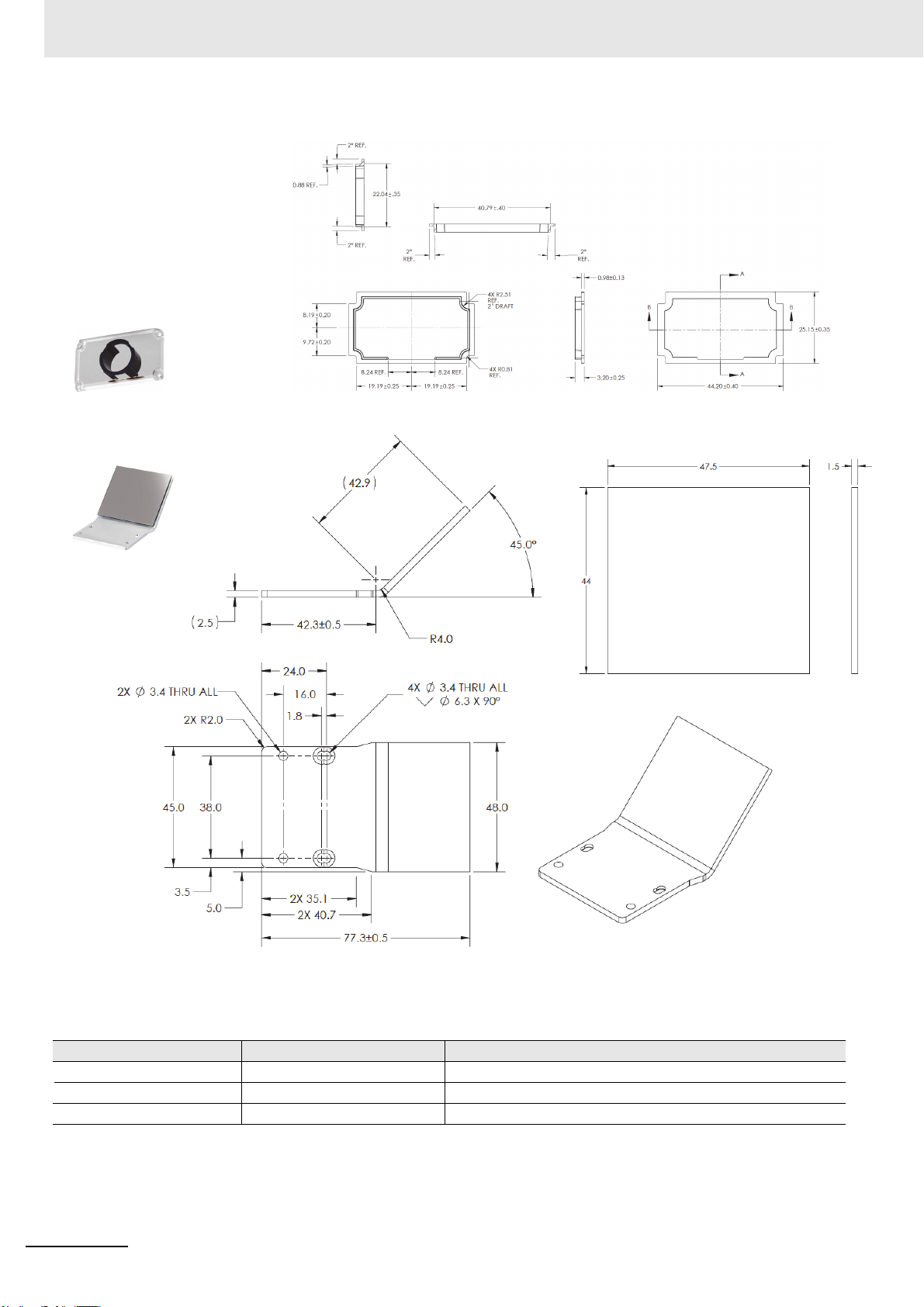
2-3-2 MicroHAWK F420-F and F430-F Accessories
L Bracket Adjustable Angle Mounting Kit
V430-AM0
¼-20 Camera Mounting Block Kit
V430-AM1
2 System Components
2-3 Accessories
2
2-3-2 MicroHAWK F420-F and F430-F Accessories
MicroHAWK F320-F / F330-F / F420-F / F430-F Smart Camera User Manual
2-11
Page 46

2 System Components
4” (102 mm) Ram Mount Stand
V430-AM2
MS-4 / MINI to V/F4XX-F Adapter Plate
V430-AM5
2-12
MicroHAWK F320-F / F330-F / F420-F / F430-F Smart Camera User Manual
Page 47

2 System Components
Smart Ring Light to V/F4XX-F Mounting Bracket
V430-AM6
QX / Vision HAWK to V/F4XX-F Adapter Plate
V430-AM7
2-3 Accessories
2
2-3-2 MicroHAWK F420-F and F430-F Accessories
MicroHAWK F320-F / F330-F / F420-F / F430-F Smart Camera User Manual
2-13
Page 48
2 System Components
Front Window Installation Kit
V430-AF10 *
Diffuser Installation Kit
V430-AF11 *
Polarizer Installation Kit
V430-AF12 *
YAG Filter Installation Kit
V430-AF4
ESD-Safe Window Installation Kit
V430-AF5
Right Angle Mirror Installation Kit
V430-AF3
* Note: The accessories V430-AF10, AF11, and AF12 are used for MicroHAWK F4X0-FXXXXXXX-XXX cameras in this manual. The prior
generation MicroHAWK F430-FXXXXXXX camera uses accessory part numbers V430-AF0, AF1, and AF2. Please select the correct
accessory from the table based on your camera part number format.
Accessory Prior F4X0-FXXXXXXX Camera
Front Window Installation Kit
Diffuser Installation Kit
Polarizer Installation Kit
V430-AF0
V430-AF1
V430-AF2
2-14
New F4X0-FXXXXXXX-XXX Camera
V430-AF10
V430-AF11
V430-AF12
MicroHAWK F320-F / F330-F / F420-F / F430-F Smart Camera User Manual
Page 49

2 System Components
Red Filter Installation Kit
V430-AF6
Blue Filter Installation Kit
V430-AF7
Red Light Installation Kit
V430-ALR
White Light Installation Kit
V430-ALW
Blue Light Installation Kit
V430-ALB
IR Light Installation Kit
V430-ALI
QX-1 Interconnect Module – Power, Trigger, Smart Light Control Breakout
98-000103-02
2-3 Accessories
2
2-3-2 MicroHAWK F420-F and F430-F Accessories
MicroHAWK F320-F / F330-F / F420-F / F430-F Smart Camera User Manual
2-15
Page 50
2 System Components
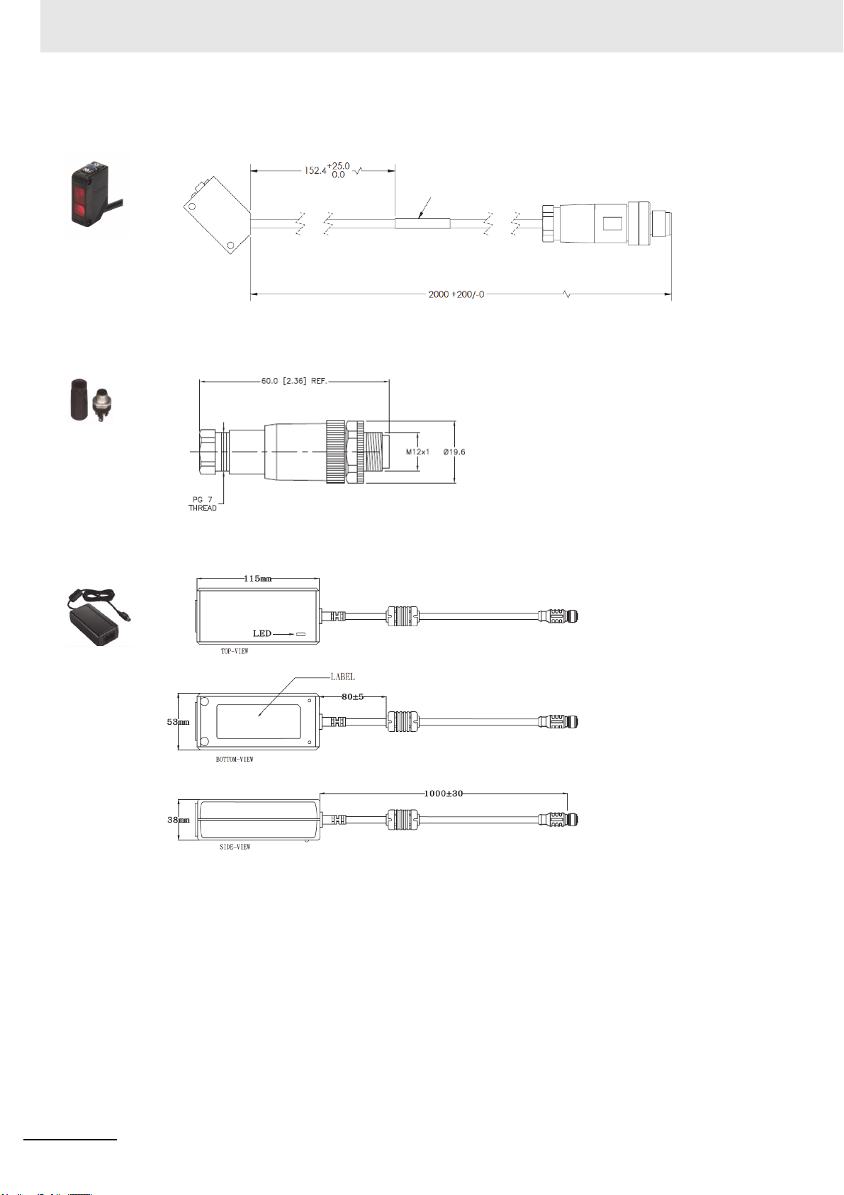
QX-1 Photo Sensor, M12 4-Pin Plug, NPN – 2 Meters – Light ON / Dark ON
99-9000016-01
QX-1 Field-Wireable M12 4-Pin Plug for Any Trigger Source or Photo Sensor – Screw Terminals
98-9000239-01
Power Supply, 100-240VAC, +24VDC, M12 12-Pin Socket – 1 Meter – U.S. / Euro Plug
97-000012-01
2-16
MicroHAWK F320-F / F330-F / F420-F / F430-F Smart Camera User Manual
Page 51

2 System Components
Omron Microscan Smart Light Series – Integrated Power and Strobe Control Module
See Omron Microscan Smart Light Offering – Ring, DOAL, Large Area Lighting
2-3 Accessories
2
2-3-2 MicroHAWK F420-F and F430-F Accessories
MicroHAWK F320-F / F330-F / F420-F / F430-F Smart Camera User Manual
2-17
Page 52

2 System Components
2-4 Hardware Configurations
Important: The following hardware configurations are examples only. Real-world application configurations may
vary considerably from those shown below.
2-4-1 Check Hardware and Connect the System
MicroHAWK F320-F
MicroHAWK F330-F
The F320-F supports Power over Ethernet (POE), allowing you to power and communicate with the device from
a single cable. The F320-F is considered a Class 0 PD (Powered Device) and will operate when connected to
appropriate PoE PSE (Power Sourcing Equipment). The PSE will either provide power on an unused data pair
(Alternative B) or on the data pair (Alternative A) which depends on the PSE. The F320-F supports both Mode A
and Mode B per the PoE standard, IEEE802.3af.
When the F320-F is connected to the Cat5E cable, it will automatically present a Powered Device (PD) signature
to the Power Sourcing Equipment (PSE), or PoE Mid-Span Equipment, when requested. The equipment will then
recognize that a powered device is connected to that line and will supply power.
Omron recommends that you contact your network or IT administrator for further configuration details. You can
connect to a non-PoE network using a PoE Injector, Omron part number V330-AP1.
2-18
MicroHAWK F320-F / F330-F / F420-F / F430-F Smart Camera User Manual
Page 53

2 System Components
F420-F with DB15 to BUS Power USB Type A
F420-F with DB15 to Ext. Power/USB Type A
Integrated
Corner-Exit
Cable
Accessory USB
Cable to Host
To H o s t
To H ost
Integrated
Corner-Exit
Cable
Accessory USB
Cable to Host
Power Supply
Note: BUS-powered cable delivers reduced illumination –
approximately 30% less brightness.
F420-F with DB15 to Ext. Power/RS-232
Power
Supply
To h ost
Integrated
Corner-Exit
Cable
F420-F with DB15 to Ext. Power/USB, I/O
To
Trigg er
Accessory
USB Cable
to Host
Integrated
Corner-Exit
Cable
To
Power
Supply
MicroHAWK F420-F
• Mount the camera securely in its stand (not supplied).
• Mount the camera as required by the application.
• Connect the integrated corner-exit cable to the MicroHAWK F420-F.
• Connect the accessory USB cable to the integrated corner-exit cable.
• Connect the USB Type A side of the USB cable to the host.
• Connect the power cable into the power source.
2-4 Hardware Configurations
2
2-4-1 Check Hardware and Connect the System
MicroHAWK F320-F / F330-F / F420-F / F430-F Smart Camera User Manual
2-19
Page 54

2 System Components
F420-F with DB15 to USB/RS-232, Triggered
To H o s t
To Trigger
To Power Supply
To H o s t
(RS-232)
Integrated
Corner-Exit
Cable
Accessory
USB Cable
to Host
F420-F with IB-131 and IC-332
To
power
supply
IC-332
To external
trigger
To
Host
2-20
MicroHAWK F320-F / F330-F / F420-F / F430-F Smart Camera User Manual
Page 55

2 System Components
To P o w e r
Supply
(12-Pin Plug)
To H ost
(Ethernet
8-Pin Plug
to RJ45)
F430-F Simple Configuration
Common
(12-Pin Plug
to 12-Pin
Socket)
To H o s t
(Ethernet
8-Pin Plug
to RJ45)
To Trigger
To P ow er
Supply
F430-F with QX-1 Interface Device
F430-F M12 12-Pin Socket to 9-Pin Socket and M12 Plug
To Power Supply or: Flying Lead Cable
(61-000167-02); QX-1; MS-Connect 210.
To H ost
(RS-232)
To E t her n et
MicroHAWK F430-F
• Mount the camera securely in its stand (not supplied).
• Mount the camera as required by the application.
• Connect the power cable to the MicroHAWK F430-F.
• Connect the Ethernet cable to the MicroHAWK F430-F.
• Connect the Ethernet cable to the host.
• Connect the power cable into the power source.
2-4 Hardware Configurations
2
2-4-1 Check Hardware and Connect the System
MicroHAWK F320-F / F330-F / F420-F / F430-F Smart Camera User Manual
2-21
Page 56

2 System Components
2-5 Mounting the Camera
2-5-1 Mount and Position the Camera
1
Position the camera at a focal distance of one inch or more from a test object.
2
Tip the camera relative to the object to avoid the glare of direct (specular) reflection. The case
parting line should be perpendicular to the plane of the symbol by either pitching the symbol or
the camera. Avoid excessive skew or pitch. Maximum skew is ±30°; maximum pitch is ±30°.
2-22
MicroHAWK F320-F / F330-F / F420-F / F430-F Smart Camera User Manual
Page 57

2-6 I/O Wiring
2 System Components
2-6-1 MicroHAWK F420-F
Direct Input / Output Diagrams
2-6 I/O Wiring
2
2-6-1 MicroHAWK F420-F
MicroHAWK F320-F / F330-F / F420-F / F430-F Smart Camera User Manual
2-23
Page 58

2 System Components
Optoisolator Trigger Inputs for IC-332
2-24
New Master Pin
MicroHAWK F320-F / F330-F / F420-F / F430-F Smart Camera User Manual
Page 59

2-6-2 MicroHAWK F430-F
Optoisolated Outputs
2 System Components
The camera has optoisolated outputs that can transfer signals from the camera to
peripherals. Outputs can be configured as either NPN or PNP, but NPN and PNP cannot be mixed in a
system, because the output common is shared by all outputs.
NPN Output for Host Input
2-6 I/O Wiring
2
2-6-2 MicroHAWK F430-F
MicroHAWK F320-F / F330-F / F420-F / F430-F Smart Camera User Manual
2-25
Page 60

2 System Components
NPN Output for External Load
2-26
MicroHAWK F320-F / F330-F / F420-F / F430-F Smart Camera User Manual
Page 61

PNP Output for Host Input
2 System Components
2-6 I/O Wiring
2
2-6-2 MicroHAWK F430-F
MicroHAWK F320-F / F330-F / F420-F / F430-F Smart Camera User Manual
2-27
Page 62

2 System Components
PNP Output for Ecternal Load
2-28
MicroHAWK F320-F / F330-F / F420-F / F430-F Smart Camera User Manual
Page 63

2 System Components
Optoisolated Inputs
NPN Output for Host Input
All discrete inputs are optoisolated. Inputs can be configured as either NPN or PNP, but NPN and PNP
cannot be mixed in a system, because the input common is shared by all inputs.
NPN
2-6 I/O Wiring
2
2-6-2 MicroHAWK F430-F
MicroHAWK F320-F / F330-F / F420-F / F430-F Smart Camera User Manual
2-29
Page 64

2 System Components
PNP
2-30
MicroHAWK F320-F / F330-F / F420-F / F430-F Smart Camera User Manual
Page 65

2-7 Grounding and Power
An earth ground is provided through the cable shields and chassis of the camera.
Smart
Camera
2-7-1 Ground and Shield Considerations
Proper grounding is necessary for operator safety, noise reduction, and the protection of equipment
from voltage transients. Buildings, including any steelwork, all circuits, and all junction boxes must be
grounded directly to an earth ground in compliance with local and national electrical codes.
2 System Components
2-7 Grounding and Power
2
2-7-1 Ground and Shield Considerations
Ground Loops
Ground loops (signal degradation due to different ground potentials in communicating devices) can be
eliminated or minimized by ensuring that both the host, imager, and their power supplies are connected
to a common earth ground.
MicroHAWK F320-F / F330-F / F420-F / F430-F Smart Camera User Manual
2-31
Page 66

2 System Components
Expected Power and Ground Connections for Proper Operation
Grounding Notes
• Ensure that mounting bracket “Earth” is at the same potential as power source “Earth”.
• Supply “Return” and “Earth” ground must be stable, low-impedance reference points.
• “2-Terminal Power Supply” must still provide an “Earth” connection to the imager.
• “Signal Ground” can be used for communications and/or discrete signal ground reference. It must not
be used as Power Ground or Earth Ground.
Power Requirements
Refer to this table when determining the power requirements for your camera.
Power Supply Voltage Current Consumption
F320-F 5 VDC +/- 5% 450 mA at 5 VDC (max.)
F330-F Source: 44-57 VDC IEEE802.3af POE Max Current: 0.090 A
F420-F 5 VDC +/- 5% 650 mA at 5 VDC (max.)
F430-F 5 to 30.0 VDC, 200 mV p-p max ripple 0.18 A at 24 VDC (max.)
2-32
MicroHAWK F320-F / F330-F / F420-F / F430-F Smart Camera User Manual
Page 67

2 System Components
2-8 I/O Filtering and Debounce
Trigger Debounce is the ability of the system to accommodate switching noise on a trigger state
change – a common issue with relays that have some intermittent contact while engaging.
Trigger overruns (when the vision system is triggered faster than the device can process) can be
avoided by increasing the “debounce” time in the camera definition file located in the C:\Microscan
\Vscape\Drivers\CamDefs directory.
The I/O Line Debounce High Time and I/O Line Debounce Low Time can be added to the file as in the
example below. Debounce time is 1 ms (1,000 μs).
Note: Although the value entered for the "I/O Line Debounce Time" is in microseconds, it will only be
rounded up to a millisecond value. For example, entering the value 1001 will resolve to 2 ms; entering a
value of 2800 will resolve to 3 ms.
The min value for "I/O Line Debounce Time" is 0, which disables software debounce altogether. The
maximum value is 100000 (100 ms).
This is the the standard debounce as described for the trigger:
I/O Line Debounce High Time 1000 //usecs (default is 0)
I/O Line Debounce Low Time 1000 //usecs (default is 0)
The smart cameras have an I/O Line Filter Time as well:
I/O Line Filter High Time 100 //usecs (default is 100)
I/O Line Filter Low Time 100 //usecs (default is 100)
2-8 I/O Filtering and Debounce
2
2-7-1 Ground and Shield Considerations
I/O Filter is the ability to ignore any signals on the l/O lines that are less that the “Filter Time” long.
Sometimes, electrical interference puts spikes on the line. This feature makes it ignore them until the
signal that is seen on the I/O line is longer than the filter time.
MicroHAWK F320-F / F330-F / F420-F / F430-F Smart Camera User Manual
2-33
Page 68

2 System Components
2-9 Camera Definition File Example
// Camera Definition File
// Version: 1.04
Camera Name MicroHAWK 1280x960 // Name Displayed in Camdef Selection Dialog
Digitizer Type 6001 // Number associated with Trident
SXGA
Stride 1280 // Image Width
Rows 960 // Image Height
X Offset 0 // Image X Offset
Y Offset 0 // Image Y Offset
Bits Per Pixel 8 // Bits that represent Pixel Value
Pixel Type 0 // Type of Pixel: MONOCHROME=0, COLOR_RGB=1,
COLOR_BGR=2, COLOR_BAYGR8=3, COLOR_BAYRG8=4, COLOR_BAYGB8=5, COLOR_BAYBG8=6, COLOR_HSI=7
Image Structure 1 // Pixel Organization: Packed=1, TwoPlanes = 2, ThreePlanes = 3
Async Control 1 // Controllable shutter time. Usually using a pulse width
specified in usecs
Usecs Per Frame 18518 // Fastest time to acquire a frame: 54 FPS
Binning 0
Zoomed 0
// I/O Configuration
GPIO Edit Mask 0x0000
GPIO Defaults 0x0001 // 1 General Purpose Input 3 General Purpose Outputs
GPIO Count 4
GPIO Inputs 1
GPIO Outputs 3
Sensors 1 // One input dedicated to Trigger signal
Strobes 0
Virtual I/O 2048
I/O Line Filter High Time 100 //usecs (default is 100)
I/O Line Filter Low Time 100 //usecs (default is 100)
I/O Line Debounce High Time 0 //usecs (default is 0)
I/O Line Debounce Low Time 0 //usecs (default is 0)
Sensor Trigger Delay Time 0 //usecs
Custom External Strobe Delay Time0 //usecs
// Focus & Photometry Ranges
Gain Dflt 20
Gain Min 0
Gain Max 100 // 0 to 100%
Exp Dflt 4000
Exp Min 66
Exp Max 58825 // 1/17 to 1/15,000
Focus Dflt 100 // 100 mm default
Focus Min 50
Focus Max 500 // 50 to 500 mm
// -1 Disables timeout feature
2-34
MicroHAWK F320-F / F330-F / F420-F / F430-F Smart Camera User Manual
Page 69
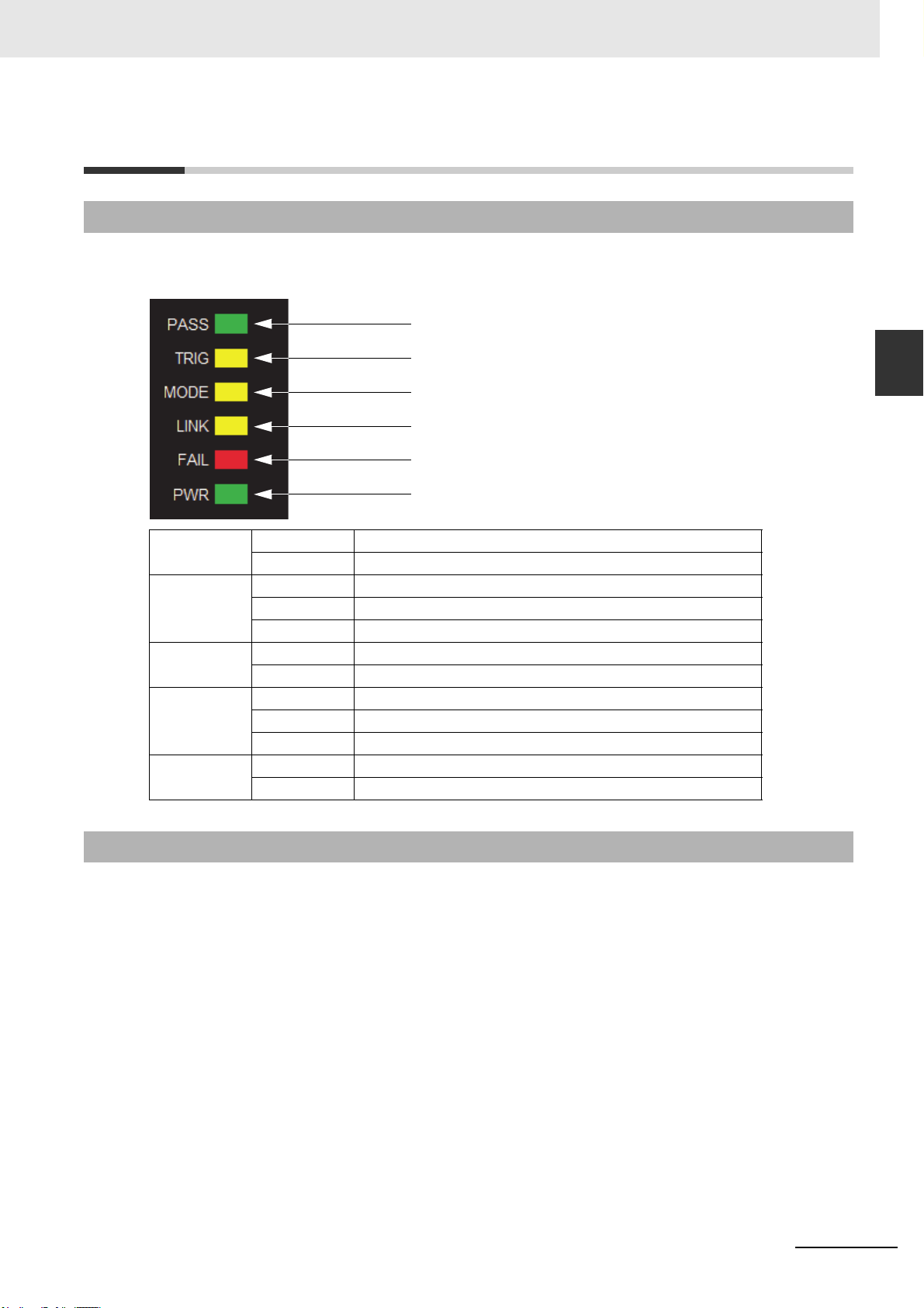
2-10 Status Indicators
Trigger Status
Inspection Status
Camera Status
Communication Status
Power Status
Inspection Status
2-10-1 MicroHAWK F420-F / F430-F Status Indicators
The top of the MicroHAWK F420-F and F430-F Smart Cameras have multiple LEDs that indicate different
inspection, trigger, camera, communication, and power states.
2 System Components
2-10 Status Indicators
2
2-10-1 MicroHAWK F420-F / F430-F Status Indicators
PASS/FAIL
TRIG
MODE
LINK
PWR
On Active State
Off Inactive State
On Steady Continuous Trigger
Off Waiting for Trigger Event
On Flashing Trigger Event
On Steady Unit Ready
Off Unit Not Ready
On Steady Link Established
Off No Link/Activity
On Flashing Link Established and Activity on Link
On Power On
Off No Power Applied to Unit
2-10-2 Additional User Feedback
• Green Flash – A green flash from the front of the unit indicates a Good Read.
• Blue Targeting Pattern – The blue targeting pattern from the front of the unit allows the user to
center an object in the camera’s field of view.
MicroHAWK F320-F / F330-F / F420-F / F430-F Smart Camera User Manual
2-35
Page 70

2 System Components
2-36
MicroHAWK F320-F / F330-F / F420-F / F430-F Smart Camera User Manual
Page 71

Getting Started with AutoVISION
This section briefly describes how to set up and use a MicroHAWK Smart Camera with
AutoVISION Software.
3-1 Setting Up a Job in AutoVISION . . . . . . . . . . . . . . . . . . . . . . . . . . . . . . . . . . 3-2
3
MicroHAWK F320-F / F330-F / F420-F / F430-F Smart Camera User Manual
3-1
Page 72

3 Getting Started with AutoVISION
3-1 Setting Up a Job in AutoVISION
AutoVISION is a critical component of the camera’s functionality. Designed for use with MicroHAWK
Smart Cameras, AutoVISION provides an intuitive interface, step-by-step configuration, and a library of
presets that allow easy setup and deployment. For more complex vision applications, the system can
be upgraded from AutoVISION to Visionscape.
The MicroHAWK F430-F Smart Camera is used as an example in the following procedure.
Item Part Number Description
1 F430-F[XXX][Y][ZZZ]-[L][C][P] F430-F
2 97-000012-01 Power Supply, 100-240VAC, +24VDC, M12 12-Pin Socket
3 98-000103-02 QX-1 Interface Device
4 61-000162-02 Cordset, Common, M12 12-Pin Socket (Screw-On) to M12 12-Pin Plug
5 61-000160-03 Cordset, Host, Ethernet, M12 8-Pin Plug (Screw-On) to RJ45, 1 m
6 99-9000016-01
Photo Sensor, M12 4-Pin Plug, NPN, Dark On or Light On (Selectable), 2 m
1. Configure Hardware
• Mount the camera as required by the application.
• Connect the Ethernet cable from "B" on the camera to the network.
• Connect the power supply to "3" on the QX-1.
• Connect the photo sensor to "T" on the QX-1.
• Connect the "Common" cable to "2" on the QX-1 and "A" on the camera.
• Plug in the power supply.
3-2
MicroHAWK F320-F / F330-F / F420-F / F430-F Smart Camera User Manual
Page 73

3 Getting Started with AutoVISION
1
4
5
3
2
6
Common
(12-Pin
Plug to
12-Pin
Socket)
To H o s t
(Ethernet
8-Pin Plug
to RJ45)
To
Trigger
To
Power
Supply
F430-F with QX-1 Interface Device
See Appendix A, Connector Pinouts,
for the camera’s pin assignments.
3-1 Setting Up a Job in AutoVISION
3
MicroHAWK F320-F / F330-F / F420-F / F430-F Smart Camera User Manual
3-3
Page 74

3 Getting Started with AutoVISION
2. Select in Connect View; Create a Job; Adjust Camera Settings
AutoVISION's Connect view allows you to select your device and configure its settings, and to create a
new job. The Select Device drop down menu provides a list of available devices. Hover the mouse
over a device to see its details.
Click the lock icon to take control of the camera. When you have control of the camera, the Modify
button will appear beneath the camera settings. Click the Modify button to adjust camera settings.
3-4
MicroHAWK F320-F / F330-F / F420-F / F430-F Smart Camera User Manual
Page 75

3 Getting Started with AutoVISION
Note: If you are using a MicroHAWK F420-F with a USB cable, the driver has already configured your PC
address. If you are using a MicroHAWK F430-F, you must set the PC to the same IP range as the default IP
address. Default IP address: 192.168.188.2. Set the PC to the same IP range (example: 192.168.188.100).
3-1 Setting Up a Job in AutoVISION
3
Important: When modifying camera settings, you will need to enter a
camera if a password has been defined.
Once you have selected your camera, adjusted its settings, and created a new job, you will move to the
Image view. This view allows you to Auto Calibrate the camera, and to manually adjust the camera's
Exposure, Gain, and Focus, and also to set the Lighting Mode (On, Off, or Strobe).
username and password for the
MicroHAWK F320-F / F330-F / F420-F / F430-F Smart Camera User Manual
3-5
Page 76

3 Getting Started with AutoVISION
3. Edit the Job in AutoVISION
After you have created a new job, loaded a job from your PC, or uploaded a job from the camera, you
will proceed to the Edit view to refine your machine vision job. The Camera parameters below the
captured image allow you to set Gain, Exposure, Focus, Trigger, and Lighting. Inspection Outputs
options allow you to connect your job to the outside world. This is also the view where you can add
multiple tools to the job. The tool icons are located above the main view area.
3-6
MicroHAWK F320-F / F330-F / F420-F / F430-F Smart Camera User Manual
Page 77

3 Getting Started with AutoVISION
4. Run the Job in AutoVISION
Going to the
Run
view will automatically download your job to the camera and start it running.
3-1 Setting Up a Job in AutoVISION
3
5. Save the Job
Click the Save to Camera icon on the File menu bar to save the job to the smart camera.
MicroHAWK F320-F / F330-F / F420-F / F430-F Smart Camera User Manual
3-7
Page 78

3 Getting Started with AutoVISION
3-8
MicroHAWK F320-F / F330-F / F420-F / F430-F Smart Camera User Manual
Page 79

Optics and Lighting
This section describes the optical and illumination characteristics of MicroHAWK F320-F,
F330-F, F420-F and F430-F Smart Cameras.
4-1 Optics . . . . . . . . . . . . . . . . . . . . . . . . . . . . . . . . . . . . . . . . . . . . . . . . . . . . . . . . 4-2
4-2 MicroHAWK Illumination . . . . . . . . . . . . . . . . . . . . . . . . . . . . . . . . . . . . . . . . 4-4
4-3 Machine Vision Lighting Principles . . . . . . . . . . . . . . . . . . . . . . . . . . . . . . . 4-5
4-4 MicroHAWK External Illumination Control and Wiring . . . . . . . . . . . . . . . . 4-6
4
MicroHAWK F320-F / F330-F / F420-F / F430-F Smart Camera User Manual
4-1
Page 80

4 Optics and Lighting
4-1 Optics
The monochrome and color versions of the MicroHAWK F320-F, F330-F. F420-F, and F430-F have a
built-in CMOS sensor, available in Standard Density, High Density, and Ultra-High Density.
Important: UHD Fixed Focus is only available in 64 mm and 400 mm distances.
UHD Autofocus is only available for SXGA MicroHAWK F320-F, F330-F, F420-F, and F430-F cameras.
4-1-1 Sensor Table
Pixels (H x V) Shutter Frames per Second
WVGA 752 x 480, 0.3 MP, Mono Global 52 fps
SXGA 1280 x 960, 1.2 MP, Mono Global 40 fps
QSXGA 2592 x 1944, 5 MP, Color Rolling 5 fps
4-1-2 MicroHAWK Read Ranges
Fixed Focus Field of View (mm) - Wide Lens
0.3 MP 1.2 MP 5 MP
Distance (mm) Width Height Width Height Width Height
50 49 32 53 39 50 38
64 62 39 66 49 63 47
81 76 49 81 61 78 58
102 95 60 101 75 96 72
133 121 78 129 97 124 92
190 171 109 182 136 174 130
300 266 170 283 213 271 202
400 353 225 376 282 359 268
Fixed Focus Field of View (mm) - Medium Lens
0.3 MP 1.2 MP 5 MP
Distance (mm) Width Height Width Height Width Height
50 34 22 36 27 35 26
64 43 27 45 34 43 32
81 53 34 56 42 54 40
102 66 42 70 52 67 50
133 84 54 90 67 86 64
190 119 76 126 95 121 90
300 185 118 196 147 188 140
400 245 156 260 195 249 186
Fixed Focus Field of View (mm) - Narrow Lens
0.3 MP 1.2 MP 5 MP
Distance (mm) Width Height Width Height Width Height
50 15 10 16 12 16 12
64 19 12 21 15 20 15
81 24 15 25 19 24 18
102 30 19 32 24 30 22
133 38 24 40 30 39 29
190 54 34 57 43 54 41
300 83 53 89 67 85 63
400 111 71 118 88 113 84
4-2
MicroHAWK F320-F / F330-F / F420-F / F430-F Smart Camera User Manual
Page 81

4 Optics and Lighting
Autofocus Field of View (mm) - Wide Lens
0.3 MP 1.2 MP 5 MP
Distance (mm) Width Height Width Height Width Height
50 51 33 55 41 52 39
100 97 62 103 77 98 73
150 142 90 151 113 144 107
200 187 119 199 149 190 142
250 232 148 247 185 236 176
300 277 177 295 221 282 210
Autofocus Field of View (mm) - Medium Lens
0.3 MP 1.2 MP 5 MP
Distance (mm) Width Height Width Height Width Height
50 33 21 36 27 34 25
100 63 40 67 50 64 48
150 92 59 98 73 94 70
200 121 77 129 97 123 92
250 151 96 160 120 153 114
300 180 115 191 144 183 136
4-1 Optics
4
Autofocus Field of View (mm) - Narrow Lens
0.3 MP 1.2 MP 5 MP
Distance (mm) Width Height Width Height Width Height
50 15 10 16 12 16 12
100 29 19 31 23 30 22
150 43 27 45 34 43 32
Long Range Autofocus Field of View (mm)
0.3 MP 1.2 MP 5 MP
Distance (mm) Width Height Width Height Width Height
75 22 14 24 18 23 17
100 29 19 31 23 30 22
200 56 36 60 45 57 43
300 83 53 89 67 85 63
400 111 71 118 88 113 84
500 138 88 147 110 140 105
600 165 105 176 132 168 125
700 192 123 204 153 196 146
800 219 140 233 175 223 166
900 247 157 262 197 251 187
1000 274 175 291 218 279 208
1200 328 209 349 262 334 249
1300 355 227 378 283 362 270
1400 382 244 407 305 389 290
1500 410 261 436 327 417 311
4-1-2 MicroHAWK Read Ranges
MicroHAWK F320-F / F330-F / F420-F / F430-F Smart Camera User Manual
4-3
Page 82

4 Optics and Lighting
F430-F
F420-F
F430-F with
Ring Light
Option
F320-F
F330-F
4-2 MicroHAWK Illumination
F420-F and F430-F Inner LEDs: 4 white, 4 red (625 nm nominal).
F420-F and F430-F Outer LEDs: 8 high-output white or red (617 nm nominal).
F420-F and F430-F have both inner and outer LEDs. Options are also available for IR and blue outer LEDs.
F320-F and F330-F only have inner LEDs.
4-2-1 LED Modules
Description Left P/N Right P/N LED P/N Wavelength
Expansion, Red 43-9500055-01 43-9500056-01 LA E65F-CAEB-24-1 617 nm
Expansion, White 43-9500055-02 43-9500056-02 NFSW036BLT b3-b6/P9-P12 N/A
Expansion, IR 43-9500055-03 43-9500056-03 SFH 4259S 850 nm
Expansion, Blue 43-9500055-04 43-9500056-04 LB E63C-T2V2-35-34 469 nm
4-4
MicroHAWK F320-F / F330-F / F420-F / F430-F Smart Camera User Manual
Page 83

4 Optics and Lighting
Before correct lighting
After correct lighting with a
NERLITE Illuminator
4-3 Machine Vision Lighting Principles
Proper lighting is critical to the success of a machine vision application. The smart camera features
integrated lighting (built-in red LEDs for monochrome sensors and white LEDs for color sensors).
Depending on the requirements of your application, you may also need
Microscan’s NERLITE family of machine vision lighting products.
Consider the following when setting up your application:
• Is the surface of the object flat, slightly bumpy, or very bumpy?
• Is the surface matte or shiny?
• Is the object curved or flat?
• What is the color of the object or area being inspected?
• Is the object moving or stationary?
Machine vision lighting should maximize contrast of the areas or features being inspected while minimizing
the contrast of everything else.
external lighting from Omron
4-3 Machine Vision Lighting Principles
4
4-2-1 LED Modules
MicroHAWK F320-F / F330-F / F420-F / F430-F Smart Camera User Manual
4-5
Page 84

4 Optics and Lighting
Figure A
MAX Series Illuminator
with power supply
1
Customer
supplied
signal source
Customer
supplied
signal source
11
Figure C
MAX Series Illuminator
with customer supplied
strobe trigger
signal source
Figure B
MAX Series Illuminator with
customer supplied dimming
or on-off signal source
4-4 MicroHAWK F430-F External
Illumination Control and Wiring
The MicroHAWK F430-F Smart Camera supports external lighting with Omron Microscan’s NERLITE
Smart Series lights. The diagrams below demonstrates how the camera and light can be configured.
The light is controlled using the Lighting control in the Camera configuration settings of AutoVISION
software.
3
2
Item Description Part Number
1
MAX Series Lights NER-011660XXXG
Power Supply DSP100 24VDC 4.2A DIN Mount 97-000006-01
2
Power Supply DSP60 24VDC 2.5A DIN Mount NER-011504100
Cable, 5P M12 Socket To Flying Leads, 3M 61-000186-01
3
Cable, 5P M12 Socket To Flying Leads, 5M 61-000187-01
Cable, 5P M12 Plug To 5P M12 Socket, 1M 61-000184-01
4
Cable, 5P M12 Plug To 5P M12 Socket, 3M 61-000185-01
5
Cable, Power Smart Series to QX-1 61-000204-01
3
2
3
4-6
MicroHAWK F320-F / F330-F / F420-F / F430-F Smart Camera User Manual
Page 85

4 Optics and Lighting
Figure D
MAX Series Illuminator in a daisy
chain configuration. See figures
A, B, or C for the correct power
supply and signal connections for
your application.
1
4
4
4
3
Figure E
MAX Series Illuminators with QX-1 Interface Device.
Note: Figure E is not compatible with daisy chaining.
Powering more than one MAX via the QX-1 will exceed
the QX-1’s current capacity.
QX-1 Interface
In Strobe mode, the external illuminator is strobed with the exposure of the camera to maximize light for
the short exposure times needed in dynamic applications.
ON/OFF allows the external illuminator to be enabled and disabled using the MicroHAWK F430-F’s I/O.
4-4 MicroHAWK F430-F External Illumination Control and Wiring
Operation Cable
1
Strobe 61-000218-01, Smart Series-to-QX-1, Strobe, NPN
2
ON/OFF 61-000207-01, Smart Series-to-QX-1, ON/OFF
3
Continuous ON 61-000204-01, Smart Series-to-QX-1, Continuous
4
4-2-1 LED Modules
MicroHAWK F320-F / F330-F / F420-F / F430-F Smart Camera User Manual
4-7
Page 86

4 Optics and Lighting
F430-F Connector ASmart Series Illuminator
Connector
Smart Series Illuminator
Pin Signal Name
1
+24VDC
2
Trigger –
3
DC Ground
4
Trigger +
5
Dim
(Connector A)
Pin Signal Name
2
Power
6
Output 3
7 and 12 Ground and Output Common
2
Power
No Connection* N/A
to
to
to
to
to
4-4-1 Wiring for Strobe Illumincation (NPN)
Warning: Contact between Pin 5 (gray wire) and any ground or voltage source less than or equal to
3.5VDC may cause erratic operation in this configuration. Contact between Pin 5 (gray wire) and any
voltage source greater than 3.5VDC will damage the illuminator.
Insulate Pin 5 (gray wire)
4-8
MicroHAWK F320-F / F330-F / F420-F / F430-F Smart Camera User Manual
Page 87

4-4-2 Wiring for Strobe Illumincation (PNP)
F430-F Connector A
Smart Series Illuminator
Connector
Smart Series Illuminator
Pin Signal Name
1
+24VDC
2
Trigger –
3
DC Ground
4
Trigger +
5
Dim
(Connector A)
Pin Signal Name
2 and 12
Power and Output Common
7
Ground
7 Ground
6
Output 3
No Connection* N/A
to
to
to
to
to
Warning: Contact between Pin 5 (gray wire) and any ground or voltage source less than or equal to
3.5VDC may cause erratic operation in this configuration. Contact between Pin 5 (gray wire) and any
voltage source greater than 3.5VDC will damage the illuminator.
4 Optics and Lighting
4-4 MicroHAWK F430-F External Illumination Control and Wiring
Insulate Pin 5 (gray wire)
4
4-4-2 Wiring for Strobe Illumincation (PNP)
MicroHAWK F320-F / F330-F / F420-F / F430-F Smart Camera User Manual
4-9
Page 88

4 Optics and Lighting
F430-F Connector A
Smart Series Illuminator
Connector
Smart Series Illuminator
Pin Signal Name
1
+24VDC
2
Trigger –
3
DC Ground
4
Trigger +
5
Dim
(Connector A)
Pin Signal Name
2
Power
7 and 12 Ground and Output Common
7 and 12 Ground and Output Common
2
Power
6 Output 3
to
to
to
to
to
4-4-3 Wiring for ON/OFF Illumination (NPN Only)
Warning: Contact between Pin 5 (gray wire) and any voltage source greater than 3.5VDC will damage
the illuminator.
Insulate Pin 5 (gray wire)
4-10
MicroHAWK F320-F / F330-F / F420-F / F430-F Smart Camera User Manual
Page 89

4-4-4 Wiring for Continuous Illumination
F430-F/F420-F
Connector A
Smart Series Illuminator
Connector
Smart Series Illuminator
Pin Signal Name
1
+24VDC
2
Trigger –
3
DC Ground
4
Trigger +
5
Dim
(Connector A)
Pin Signal Name
2
Power
7
Ground
7
Ground
2
Power
No Connection* N/A
to
to
to
to
to
Warning: Contact between Pin 5 (gray wire) and any ground or voltage source less than or equal to
3.5VDC may cause erratic operation in this configuration. Contact between Pin 5 (gray wire) and any
voltage source greater than 3.5VDC will damage the illuminator.
4 Optics and Lighting
4-4 MicroHAWK F430-F External Illumination Control and Wiring
Insulate Pin 5 (gray wire)
4
4-4-4 Wiring for Continuous Illumination
MicroHAWK F320-F / F330-F / F420-F / F430-F Smart Camera User Manual
4-11
Page 90

4 Optics and Lighting
4-12
MicroHAWK F320-F / F330-F / F420-F / F430-F Smart Camera User Manual
Page 91

Appendix A - Connector Pinouts
This section contains information about the MicroHAWK, F320-F, F330-F, F420-F, and
F430-F Smart Camera’s connectors and pin assignments.
A-1 MicroHAWK F320-F Connector . . . . . . . . . . . . . . . . . . . . . . . . . . . . . . . . . . . A-2
A-2 MicroHAWK F330-F Connector . . . . . . . . . . . . . . . . . . . . . . . . . . . . . . . . . . . A-3
A-3 MicroHAWK F420-F Connector . . . . . . . . . . . . . . . . . . . . . . . . . . . . . . . . . . . A-4
A-4 MicroHAWK F430-F Connector . . . . . . . . . . . . . . . . . . . . . . . . . . . . . . . . . . . A-5
A
MicroHAWK F320-F / F330-F / F420-F / F430-F Smart Camera User Manual
A-1
Page 92

Appendix A - Connector Pinouts
A-1 MicroHAWK F320-F Connector
A-1-1 RJ50 Socket, 10 Pins
A-2
MicroHAWK F320-F / F330-F / F420-F / F430-F Smart Camera User Manual
Page 93

Appendix A - Connector Pinouts
A-2 MicroHAWK F330-F Connector
A-2-1 RJ45 Connector, 8 Pins
A
A-2-1 RJ45 Connector, 8 Pins
MicroHAWK F320-F / F330-F / F420-F / F430-F Smart Camera User Manual
A-3
Page 94

Appendix A - Connector Pinouts
A-3 MicroHAWK F420-F Connector
A-3-1 High-Density 15-Pin D-Sub Socket
A-4
MicroHAWK F320-F / F330-F / F420-F / F430-F Smart Camera User Manual
Page 95

Appendix A - Connector Pinouts
A-4 MicroHAWK F430-F Connector
A-4-1 Connector A - M12 12-Pin Plug - Power, I/O, and Serial
A
A-4-1 Connector A - M12 12-Pin Plug - Power, I/O, and Serial
Pin Function
1 Trigger
2 Power
3 Default
4 New Master
5 Output 1
6 Output 3
7 Ground
8 Input Common
9 RS-232 (Host) RxD
10 RS-232 (Host) TxD
11 Output 2
12 Output Common
MicroHAWK F320-F / F330-F / F420-F / F430-F Smart Camera User Manual
A-5
Page 96

Appendix A - Connector Pinouts
A-4-2 Connector B - M12 8-Pin Socket - Ethernet
Pin Function
1V+
2 V–
3 V–
4 TX (–)
5 RX (+)
6 TX (+)
7 V+
8 RX (–)
A-6
MicroHAWK F320-F / F330-F / F420-F / F430-F Smart Camera User Manual
Page 97

Appendix B - Cable Specifications
This section contains images, pin assignments, and wire colors for MicroHAWK
F320-F, F330-F, F420-F, and F430-F Smart Camera cables.
Note: Cable specifications are published for information only. Omron Microscan does
not guarantee the performance or quality of cables provided by other suppliers
B-1 MicroHAWK Cables. . . . . . . . . . . . . . . . . . . . . . . . . . . . . . . . . . . . . . . . . . . . . B-2
B
MicroHAWK F320-F / F330-F / F420-F / F430-F Smart Camera User Manual
B-1
Page 98

Appendices
B-1 MicroHAWK Cables
B-1-1 MicroHAWK F320-F Cables with Pinouts and Wire Colors
V320-WRX-2M – RJ50 to RS-232 and External Power Straight – 2 M
V320-WRXLR-2M – RJ50 to RS-232 and External Power Right Angle – 2 M
B-2
MicroHAWK F320-F / F330-F / F420-F / F430-F Smart Camera User Manual
Page 99

V320-W8-3M – RJ50 to Flying Leads, Straight – 3 M
Appendices
B
MicroHAWK F320-F / F330-F / F420-F / F430-F Smart Camera User Manual
B-3
Page 100

Appendices
V320-W8LR-3M – RJ50 to Flying Leads, Right Angle to the Right – 3 M
B-4
MicroHAWK F320-F / F330-F / F420-F / F430-F Smart Camera User Manual
 Loading...