

Page 1
&DW1R=(
)80(
$SSOLFDWLRQ6RIWZDUH
23(5$7,210$18$/
Front Matter
Contents
About this Manual
Basic Operating Procedures
Processing Items Setting Procedures
Monitor Mode and Run Mode
Other Functions
System Settings
Communicating with External Devices
Appendices
Revision History
Page 2

)80($SSOLFDWLRQ6RIWZDUH
2SHUDWLRQ0DQXDO
5HYLVHG'HFHPEHU
Page 3

iii
Page 4

Notice:
OMRON products are manufactured for use according to proper procedures by a qualified operator and only for the purposes described in this manual.
The following conventions are used to indicate and classify precautions in this manual. Always
heed the information prov ided w ith them . Failure to heed precau tions c an resul t in injury to people
or damage to property.
!DANGER Indicates an imminently hazardous situation which, if not avoided, will result in
death or serious injury.
!WARNING Indicates a potentially hazardous situation which, if not avoided, could result in
death or serious injury.
!Caution Indicates a potentially hazardous situation which, if not avoided, may result in
minor or moderate injury, or property damage.
OMRON Product References
All OMRON products are capitalized in this manual. The word “Unit” is also capitalized when it
refers to an OMRON product, regardless of whether or not it appears in the proper name of the
product.
Visual Aids
The following headings appear in the left column of the manual to help you locate different types
of information.
Note Indicates information of particular interest for efficient and convenient opera-
tion of the product.
1,2,3... ,QGLFDWHVOLVWVRIRQHVRUWRUDQRWKHUVXFKDVSURFHGXUHVFKHFNOLVWVHWF
Precaution Indicates information required to take full advantage of the functions and per-
formance of the product. Incorrect application methods may result in the loss
of damage or damage to the product. Read and follow all precautionary information.
CHECK Indicates points that are important in using product functions or in application
procedures.
SeeAlso Indicates where to find related information.
HELP Indicates information helpful in operation, such as the definition of terms.
¸ OMRON, 2001
All rights reserved. No part of this publication may be reproduced, stored in a retrieval system, or transmitted, in any form, or by any means, mechanical, electronic, photocopying, recording, or otherwise,
without the prior written permission of OMRON.
No patent liability is assumed with respect to the use of the information contained herein. Moreover,
because OMRON is constantly striving to improve its high-quality products, the information contained
in this manual is subject to change without notice. Every preca ution has been taken in the prepa ration
of this manual. Nevertheless, OMRON assumes no responsibility for errors or omissions. Neither is
any liability assumed for damages resulting from the use of the information contained in this publication.
iv
Page 5

TABLE OF CONTENTS
SECTION 1
Basic Operating Procedures. . . . . . . . . . . . . . . . . . . . . . . . . . 1-(1)
1-1 Using this Manual . . . . . . . . . . . . . . . . . . . . . . . . . . . . . . . . . . . . . . . . . . . . . 1-(2)
1-2 Operational Flow. . . . . . . . . . . . . . . . . . . . . . . . . . . . . . . . . . . . . . . . . . . . . . 1-(3)
1-3 Installing the Application Software. . . . . . . . . . . . . . . . . . . . . . . . . . . . . . . . 1-(4)
1-4 Displaying Images and Focussing. . . . . . . . . . . . . . . . . . . . . . . . . . . . . . . . 1-(10)
1-5 Menu Operations . . . . . . . . . . . . . . . . . . . . . . . . . . . . . . . . . . . . . . . . . . . . . 1-(12)
1-6 Basic Operations . . . . . . . . . . . . . . . . . . . . . . . . . . . . . . . . . . . . . . . . . . . . . 1-(28)
1-7 Run Mode . . . . . . . . . . . . . . . . . . . . . . . . . . . . . . . . . . . . . . . . . . . . . . . . . . 1-(62)
1-8 Saving Settings and Shutting Down . . . . . . . . . . . . . . . . . . . . . . . . . . . . . . 1-(64)
SECTION 2
Processing Items Setting Procedures . . . . . . . . . . . . . . . . . . 2-(1)
2-1 Inputting Camera Images. . . . . . . . . . . . . . . . . . . . . . . . . . . . . . . . . . . . . . .2-1-(1)
2-2 Switching Cameras . . . . . . . . . . . . . . . . . . . . . . . . . . . . . . . . . . . . . . . . . . .2-2-(1)
2-3 Changing Filtering. . . . . . . . . . . . . . . . . . . . . . . . . . . . . . . . . . . . . . . . . . . .2-3-(1)
2-4 Filtering Again. . . . . . . . . . . . . . . . . . . . . . . . . . . . . . . . . . . . . . . . . . . . . . .2-4-(1)
2-5 Binary Position Compensation . . . . . . . . . . . . . . . . . . . . . . . . . . . . . . . . . .2-5-(1)
2-6 EC Position Compensation . . . . . . . . . . . . . . . . . . . . . . . . . . . . . . . . . . . . .2-6-(1)
2-7 Edge Position Compensation. . . . . . . . . . . . . . . . . . . . . . . . . . . . . . . . . . . .2-7-(1)
2-8 Model Position Compensation. . . . . . . . . . . . . . . . . . . . . . . . . . . . . . . . . . .2-8-(1)
2-9 Circle Position Compensation. . . . . . . . . . . . . . . . . . . . . . . . . . . . . . . . . . .2-9-(1)
2-10 Reset Scroll . . . . . . . . . . . . . . . . . . . . . . . . . . . . . . . . . . . . . . . . . . . . . . . .2-10-(1)
2-11 Scroll . . . . . . . . . . . . . . . . . . . . . . . . . . . . . . . . . . . . . . . . . . . . . . . . . . . . .2-11-(1)
2-12 Detecting Binary Defects. . . . . . . . . . . . . . . . . . . . . . . . . . . . . . . . . . . . . .2-12-(1)
2-13 Classification . . . . . . . . . . . . . . . . . . . . . . . . . . . . . . . . . . . . . . . . . . . . . . .2-13-(1)
2-14 Density Defects . . . . . . . . . . . . . . . . . . . . . . . . . . . . . . . . . . . . . . . . . . . . .2-14-(1)
2-15 EC Defect. . . . . . . . . . . . . . . . . . . . . . . . . . . . . . . . . . . . . . . . . . . . . . . . . .2-15-(1)
2-16 EC Positioning. . . . . . . . . . . . . . . . . . . . . . . . . . . . . . . . . . . . . . . . . . . . . .2-16-(1)
2-17 Edge Position. . . . . . . . . . . . . . . . . . . . . . . . . . . . . . . . . . . . . . . . . . . . . . .2-17-(1)
2-18 Fine Matching . . . . . . . . . . . . . . . . . . . . . . . . . . . . . . . . . . . . . . . . . . . . . .2-18-(1)
2-19 EC Circle Count. . . . . . . . . . . . . . . . . . . . . . . . . . . . . . . . . . . . . . . . . . . . .2-19-(1)
2-20 Pattern . . . . . . . . . . . . . . . . . . . . . . . . . . . . . . . . . . . . . . . . . . . . . . . . . . . .2-20-(1)
2-21 QUEST Character Verification . . . . . . . . . . . . . . . . . . . . . . . . . . . . . . . . .2-21-(1)
2-22 Rotation Positioning . . . . . . . . . . . . . . . . . . . . . . . . . . . . . . . . . . . . . . . . .2-22-(1)
2-23 ECM Search . . . . . . . . . . . . . . . . . . . . . . . . . . . . . . . . . . . . . . . . . . . . . . . .2-23-(1)
2-24 Lot Number OCV 1. . . . . . . . . . . . . . . . . . . . . . . . . . . . . . . . . . . . . . . . . .2-24-(1)
2-25 Labeling. . . . . . . . . . . . . . . . . . . . . . . . . . . . . . . . . . . . . . . . . . . . . . . . . . .2-25-(1)
2-26 Label Data . . . . . . . . . . . . . . . . . . . . . . . . . . . . . . . . . . . . . . . . . . . . . . . . .2-26-(1)
v
Page 6

TABLE OF CONTENTS
2-27 Edge Pitch . . . . . . . . . . . . . . . . . . . . . . . . . . . . . . . . . . . . . . . . . . . . . . . . .2-27-(1)
2-28 Density Data . . . . . . . . . . . . . . . . . . . . . . . . . . . . . . . . . . . . . . . . . . . . . . .2-28-(1)
2-29 Calculation. . . . . . . . . . . . . . . . . . . . . . . . . . . . . . . . . . . . . . . . . . . . . . . . .2-29-(1)
2-30 Elapsed Time. . . . . . . . . . . . . . . . . . . . . . . . . . . . . . . . . . . . . . . . . . . . . . .2-30-(1)
2-31 Get Unit Data. . . . . . . . . . . . . . . . . . . . . . . . . . . . . . . . . . . . . . . . . . . . . . .2-31-(1)
2-32 Wait . . . . . . . . . . . . . . . . . . . . . . . . . . . . . . . . . . . . . . . . . . . . . . . . . . . . . .2-32-(1)
2-33 Set Unit Data . . . . . . . . . . . . . . . . . . . . . . . . . . . . . . . . . . . . . . . . . . . . . . .2-33-(1)
2-34 Trend Monitor . . . . . . . . . . . . . . . . . . . . . . . . . . . . . . . . . . . . . . . . . . . . . .2-34-(1)
2-35 Conditional Branching. . . . . . . . . . . . . . . . . . . . . . . . . . . . . . . . . . . . . . . .2-35-(1)
2-36 DI Branch. . . . . . . . . . . . . . . . . . . . . . . . . . . . . . . . . . . . . . . . . . . . . . . . . .2-36-(1)
2-37 End. . . . . . . . . . . . . . . . . . . . . . . . . . . . . . . . . . . . . . . . . . . . . . . . . . . . . . . 2 -37-(1)
2-38 Memory Card Data . . . . . . . . . . . . . . . . . . . . . . . . . . . . . . . . . . . . . . . . . .2-38-(1)
2-39 DO Data. . . . . . . . . . . . . . . . . . . . . . . . . . . . . . . . . . . . . . . . . . . . . . . . . . .2-39-(1)
2-40 DO Judgement. . . . . . . . . . . . . . . . . . . . . . . . . . . . . . . . . . . . . . . . . . . . . .2 -40-(1)
2-41 Host Link Data. . . . . . . . . . . . . . . . . . . . . . . . . . . . . . . . . . . . . . . . . . . . . .2-41-(1)
2-42 Normal Data. . . . . . . . . . . . . . . . . . . . . . . . . . . . . . . . . . . . . . . . . . . . . . . .2-42-(1)
2-43 Display String . . . . . . . . . . . . . . . . . . . . . . . . . . . . . . . . . . . . . . . . . . . . . .2-43-(1)
2-44 Display Measurement . . . . . . . . . . . . . . . . . . . . . . . . . . . . . . . . . . . . . . . .2-44-(1)
2-45 Display Judgement. . . . . . . . . . . . . . . . . . . . . . . . . . . . . . . . . . . . . . . . . . .2-45-(1)
2-46 Display Item. . . . . . . . . . . . . . . . . . . . . . . . . . . . . . . . . . . . . . . . . . . . . . . .2-46-(1)
2-47 Display Time . . . . . . . . . . . . . . . . . . . . . . . . . . . . . . . . . . . . . . . . . . . . . . .2-47-(1)
2-48 Display Figure . . . . . . . . . . . . . . . . . . . . . . . . . . . . . . . . . . . . . . . . . . . . . .2-48-(1)
2-49 Display Line, Dis play Box, Display Circle, and Display Cursor . . . . . . .2-49-(1)
SECTION 3
Monitor Mode and Run Mode. . . . . . . . . . . . . . . . . . . . . . . . 3-(1)
3-1 Testing Measurements. . . . . . . . . . . . . . . . . . . . . . . . . . . . . . . . . . . . . . . . . . 3-(2)
3-2 Starting Measurement . . . . . . . . . . . . . . . . . . . . . . . . . . . . . . . . . . . . . . . . . . 3-(5)
SECTION 4
Other Functions . . . . . . . . . . . . . . . . . . . . . . . . . . . . . . . . . . . 4-(1)
4-1 Changing Scenes and Scene Groups . . . . . . . . . . . . . . . . . . . . . . . . . . . . . . . 4-(2)
4-2 Backing Up Data . . . . . . . . . . . . . . . . . . . . . . . . . . . . . . . . . . . . . . . . . . . . . . 4-(9)
4-3 Clearing Measurement Values. . . . . . . . . . . . . . . . . . . . . . . . . . . . . . . . . . . 4-(24)
4-4 Checking Image Density Distribution: Line Brightness . . . . . . . . . . . . . . . 4-(25)
4-5 Checking I/O Status with External Devices . . . . . . . . . . . . . . . . . . . . . . . . 4-(28)
4-6 Memory Card Operations . . . . . . . . . . . . . . . . . . . . . . . . . . . . . . . . . . . . . . 4-(33)
vi
Page 7

TABLE OF CONTENTS
SECTION 5
System Settings . . . . . . . . . . . . . . . . . . . . . . . . . . . . . . . . . . . . 5-(1)
5-1 Entering System Mode . . . . . . . . . . . . . . . . . . . . . . . . . . . . . . . . . . . . . . . . . 5-(2)
5-2 Camera Settings. . . . . . . . . . . . . . . . . . . . . . . . . . . . . . . . . . . . . . . . . . . . . . . 5-(3)
5-3 Screen Display and Monitor . . . . . . . . . . . . . . . . . . . . . . . . . . . . . . . . . . . . . 5-(5)
5-4 Customizing Operations . . . . . . . . . . . . . . . . . . . . . . . . . . . . . . . . . . . . . . . 5-(17)
5-5 Setting Conditions for Saving Measurement Images . . . . . . . . . . . . . . . . . 5-(27)
5-6 Using BUSY Signals. . . . . . . . . . . . . . . . . . . . . . . . . . . . . . . . . . . . . . . . . . 5-(31)
5-7 Setting Startup Conditions. . . . . . . . . . . . . . . . . . . . . . . . . . . . . . . . . . . . . . 5-(33)
5-8 Setting the Calendar Date and Time (Date/Time). . . . . . . . . . . . . . . . . . . . 5-(34)
5-9 Checking System Information. . . . . . . . . . . . . . . . . . . . . . . . . . . . . . . . . . . 5-(35)
SECTION 6
Communicating with External Devices. . . . . . . . . . . . . . . . . 6-(1)
6-1 Parallel Interface . . . . . . . . . . . . . . . . . . . . . . . . . . . . . . . . . . . . . . . . . . . . .6-1-(1)
6-2 Normal Serial Interface . . . . . . . . . . . . . . . . . . . . . . . . . . . . . . . . . . . . . . . .6-2-(1)
6-3 Host Link Serial Interface . . . . . . . . . . . . . . . . . . . . . . . . . . . . . . . . . . . . . .6-3-(1)
6-4 Serial Interface Menu Operations . . . . . . . . . . . . . . . . . . . . . . . . . . . . . . . .6-4-(1)
SECTION 7
Appendices. . . . . . . . . . . . . . . . . . . . . . . . . . . . . . . . . . . . . . . . 7-(1)
7-1 Set Up Menu . . . . . . . . . . . . . . . . . . . . . . . . . . . . . . . . . . . . . . . . . . . . . . . . . 7-(2)
7-2 Troubleshooting. . . . . . . . . . . . . . . . . . . . . . . . . . . . . . . . . . . . . . . . . . . . . . . 7-(4)
7-3 FAQ. . . . . . . . . . . . . . . . . . . . . . . . . . . . . . . . . . . . . . . . . . . . . . . . . . . . . . . . 7-(9)
7-4 Terminology. . . . . . . . . . . . . . . . . . . . . . . . . . . . . . . . . . . . . . . . . . . . . . . . . 7-(12)
7-5 Character Codes. . . . . . . . . . . . . . . . . . . . . . . . . . . . . . . . . . . . . . . . . . . . . . 7-(15)
7-6 Menu Hierarchy. . . . . . . . . . . . . . . . . . . . . . . . . . . . . . . . . . . . . . . . . . . . . . 7-(16)
Revision History
vii
Page 8

$ERXWWKLV0DQXDO
This manual describes the operation of the F250-UME Application Software and it includes
the sections described below.
This is one of a pai r of manuals. R efer to the fo ll o w in g ta ble for the co nte nts of eac h m an u al .
Manual Contents Cat. No.
1:Setup Manual Provides information on system hardware and installa-
tion. Be sure to read this manual first.
This manual is provided with the Controller.
2:Operation Manual Describes the operation of the F250-UME Application
Software, including installation of the Application Software, basic operating methods, setting methods for processing items, communications methods for external
devices, and other operating procedures.
This manual is provided on CD-ROM.
Please read the above manuals carefully and be sure you understand the information provided before attempting to install or operate the Application Software.
Section 1 Basic Operating Procedures describes the basic operating procedures for the
Application Software.
Section 2 Processing Item Setting Procedures explains in more detail the basic setting
operations for the processing items that control Application Software operation.
Section 3 Testing and Starting Measurements describes the procedures used to test
operation and then actually take measurements.
Section 4 Other Functions describes additional functions, such as changing the measurement setup or backing up data.
Section 5 System Settings describes how to set conditions related to the system environ-
ment.
Section 6 Communicating with External Devices describes the methods used to connec t
to and communicate with external devices.
Section 7 Ap p e nd ic es provides information on terminology, character codes, troubleshoot-
ing, and answers to FAQs.
SCHB-736
Z153-E1-02
!WARNING Failure to read and understand the information provided in this manual may result in per-
sonal injury or death, damage to the product, or product failure. Please read each section in
its entirety and be sure you understand the information provided in the section and related
sections before attempting any of the procedures or operations given.
viii
Page 9

SECTION 1
Basic Operating Procedures
This section describes the basic operating procedures for the Application Software.
1-1 Using this Manual . . . . . . . . . . . . . . . . . . . . . . . . . . . . . . . . . . . . . . . . . . . . . . 1-(2)
1-2 Operational Flow. . . . . . . . . . . . . . . . . . . . . . . . . . . . . . . . . . . . . . . . . . . . . . . 1-(3)
1-3 Installing the Application Software. . . . . . . . . . . . . . . . . . . . . . . . . . . . . . . . . 1-(4)
1-3-1 Starting the Setup Menu . . . . . . . . . . . . . . . . . . . . . . . . . . . . . . . . . . 1-(4)
1-3-2 Selecting Installation Processing Items. . . . . . . . . . . . . . . . . . . . . . . 1-(6)
1-3-3 Executing Installation . . . . . . . . . . . . . . . . . . . . . . . . . . . . . . . . . . . . 1-(7)
1-4 Displaying Images and Focussing. . . . . . . . . . . . . . . . . . . . . . . . . . . . . . . . . . 1-(10)
1-5 Menu Operations . . . . . . . . . . . . . . . . . . . . . . . . . . . . . . . . . . . . . . . . . . . . . . . 1-(12)
1-5-1 Input Devices. . . . . . . . . . . . . . . . . . . . . . . . . . . . . . . . . . . . . . . . . . . 1-(12)
1-5-2 Screen Displays. . . . . . . . . . . . . . . . . . . . . . . . . . . . . . . . . . . . . . . . . 1-(13)
1-5-3 Creating Flowcharts . . . . . . . . . . . . . . . . . . . . . . . . . . . . . . . . . . . . . 1-(14)
1-5-4 Drawing a Region . . . . . . . . . . . . . . . . . . . . . . . . . . . . . . . . . . . . . . . 1-(24)
1-5-5 Inputting Values. . . . . . . . . . . . . . . . . . . . . . . . . . . . . . . . . . . . . . . . . 1-(26)
1-5-6 Inputting Characters . . . . . . . . . . . . . . . . . . . . . . . . . . . . . . . . . . . . . 1-(27)
1-6 Basic Operations . . . . . . . . . . . . . . . . . . . . . . . . . . . . . . . . . . . . . . . . . . . . . . . 1-(28)
1-6-1 STEP 1: Settings for Image Input . . . . . . . . . . . . . . . . . . . . . . . . . . . 1-(29)
1-6-2 STEP 2: Settings for Position Displacement Compensation. . . . . . . 1-(38)
1-6-3 STEP 3: Setting Measurement Methods . . . . . . . . . . . . . . . . . . . . . . 1-(40)
1-6-4 STEP 4: Setting Results Output Methods. . . . . . . . . . . . . . . . . . . . . 1-(58)
1-6-5 STEP 5: Start Test or Measurement . . . . . . . . . . . . . . . . . . . . . . . . . 1-(59)
1-7 Run Mode . . . . . . . . . . . . . . . . . . . . . . . . . . . . . . . . . . . . . . . . . . . . . . . . . . . . 1-(62)
1-7-1 Entering Run Mode. . . . . . . . . . . . . . . . . . . . . . . . . . . . . . . . . . . . . . 1-(62)
1-7-2 Performing Measurement . . . . . . . . . . . . . . . . . . . . . . . . . . . . . . . . . 1-(63)
1-8 Saving Settings and Shutting Down . . . . . . . . . . . . . . . . . . . . . . . . . . . . . . . . 1-(64)
1-(1)
Page 10
Using this Manual Section 1-1
1-1 Using this Manual
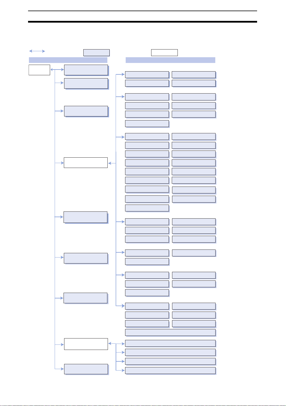
The structure of the PDF files in this manual is shown below. Bookmarks are
provided to link the initial file to sections and sections to detailed information.
Linked files
Initial File a nd Section File s
Initial file
Front Matter
About this Manual
SECTION 1
Basic Operating Procedures
SECTION 2
Detailed Setting Operations
SECTION 3
Executing Tests and
Measurements
SECTION 4
Other Functions
SECTION 5
System Settings
SECTION 6
Communicating with External
Devices
SECTION 7
Appendices
Individual files
Processing Item Files
Inputtin g I m ages
Camera image
Change filtering
Position Compensation
Binary pos. comp
Edge pos. comp
Circle pos. comp
Scroll
General Measurements
Binary defect Classification
Density defect
EC position Edge position
Fine matching
Pattern
Rotate position
Lot No. OCV1
Label data
Density data
Measurement Support
Calculation Elapsed time
Get unit data
Set unit data
Branch Control
Branch
End
Results Output
Memory card data
DO judge
Normal data
Results Display
Display string Display measure
Display judge
Display time Display figure
Display line/box/circle/cursor
Parallel Interface
Serial Interface: Normal
Serial Interface: Host Link
Serial Interface: Menu Operations
Files containing only links
Switch camera
Filtering again
EC pos. comp
Model pos. comp
Reset scroll
EC defect
EC circle count
QUEST OCV
ECM search
Labeling
Edge pitch
Wait
Trend monitor
DI branch
DO data
Host link data
Display item
This manual can
be printed out by
opening the file
and following the
instructions in the
Acrobat printing
dialog box.
1-(2)
Page 11

Operational Flow Section 1-2
1-2 Operational Flow
Preparations
Install the Application Software in the Controller. Refer to 1-3 Installing the
Application Software.
SeeAlso Refer to 1-6 Basic Operations to learn about the basic operational flow from
setting detection conditions to executing measurements.
Setting Detection Conditions
STEP 1: Make the settings required to input images. Refer to1-6-1 STEP 1:
Settings for Image Input.
STEP 2: Make settings to correct positioning. Refer to 1-6-2 STEP 2: Settings
for Position Displacement Compensation.
STEP 3: Set the actual measu remen t method s. Ref er to 1-6-3 STEP 3: Setting
Measurement Methods.
STEP 4: Make settings to output the results. Refer to 1-6-4 STEP 4: Setting
Results Output Methods.
Confirming Settings and Executing
STEP 5: Perform test measurements and start executing measurements.
Refer to 1-6-5 STEP 5: Start Test or Measurement and to SECTION 3 Monitor
Mode and Run Mode.
Selecting Processing Items that Suit the Application
Refer to SECTION 2 Processing Items Setting Procedures.
Changing and Deleting Settings
Copy, clear, and change un its and uni t names by refer to &KDQJLQJ WR2WKHU
3URFHVVLQJ,WHPVRQSDJH .
Saving Settings
1. Save detection conditions. Refer to 1-8 Saving Settings and Shutting
Down.
2. Back up imag e, s ystem, and scene data. Refer to 4-2 Backing Up Data for
information on how to back up settings.
Application Setting Operations
1. Set conditions by product type. Refer to 4-1 Changing Scenes and Scene
Groups for information on scene and scene-group functions.
2. Set system environmen t conditions . Ref er to SECTION 5 System Settings.
3. Initialize the measurem ent co nditio ns that ha v e bee se t. Ref er to 4-1-3 Ini-
tializing Measu rement Conditi ons: Clearing S cenes and 7-1 Set Up Menu.
4. Set commu nications s pecifications and I/O format f or comm unication s with
external device s. Refer to SECTION 6 Communicating with External De-
vices.
Additional Functions
1. Use Memor y Cards if required. Refer to 4-6 Memory Card Operations.
2. Check communications status with external devices if required. Refer to 4-
5 Checking I/O Status with External Devices.
Troubleshooting
HELP When an error message is displayed on the screen, refer to 7-4 Terminology.
HELP If you have a question, refer to 7-3 FAQ.
HELP If you don’t understand a term, refer to 7-4 Terminology.
1-(3)
Page 12
Installing the Application Softwar e Section 1-3
1-3 Installing the Application Software
This section describes how to install the processing items in the F250-UME
Applicati on Software to the Contr oller. The Setup Menus are used to install
these processing items.
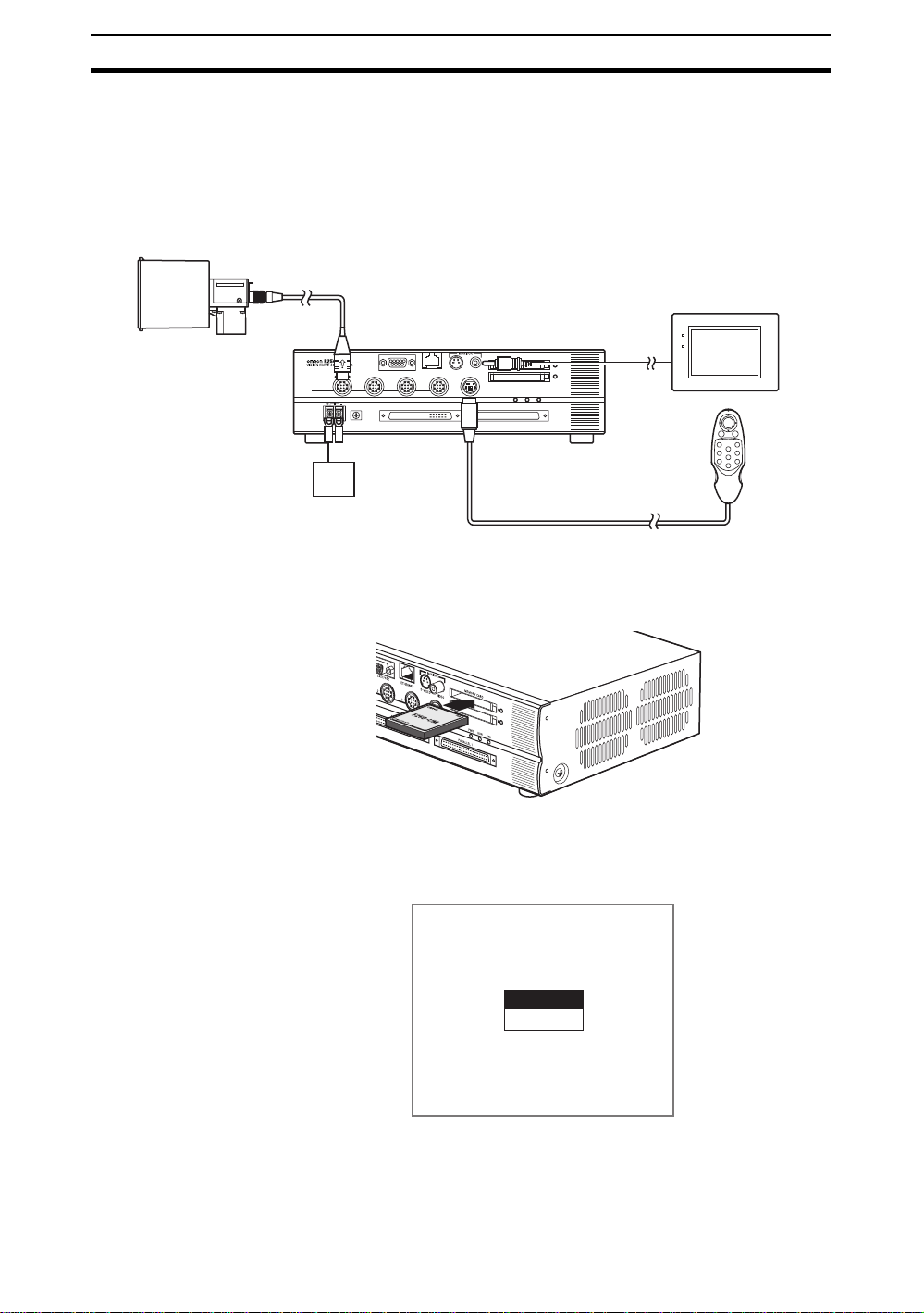
1-3-1 Starting the Setup M enu
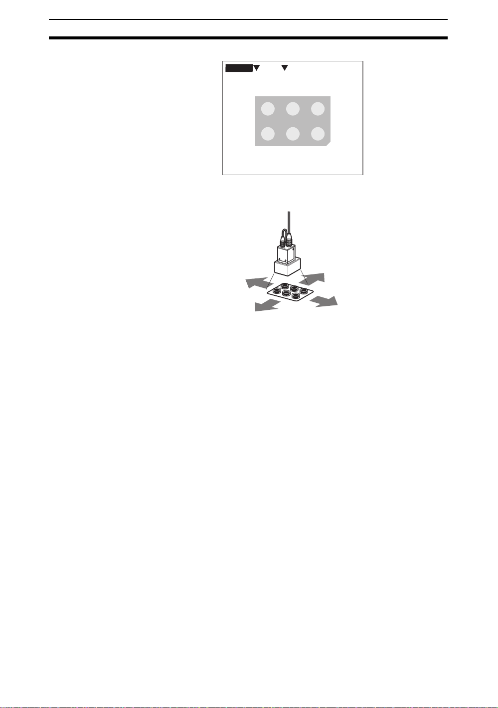
1. Check that the basic components are connected.
Camera
Monitor
Power supply
Console
POWER
SYNC
CHECK Always refer to the Setup Manual when connecting components or wiring the
power supply or ground wires.
2. Mount the F250-UME Application Software Card to Memory Card slot 0.
3. Turn ON the power supply switch to the Monitor.
4. Turn ON the Controller power supply.
The Language Selection Screen for the Setup Menus will be displayed.
1-(4)
Language
Japanese
English
CHECK The language selected here applies only to the Setup Menus.
Page 13

Installing the Application Softwar e Section 1-3
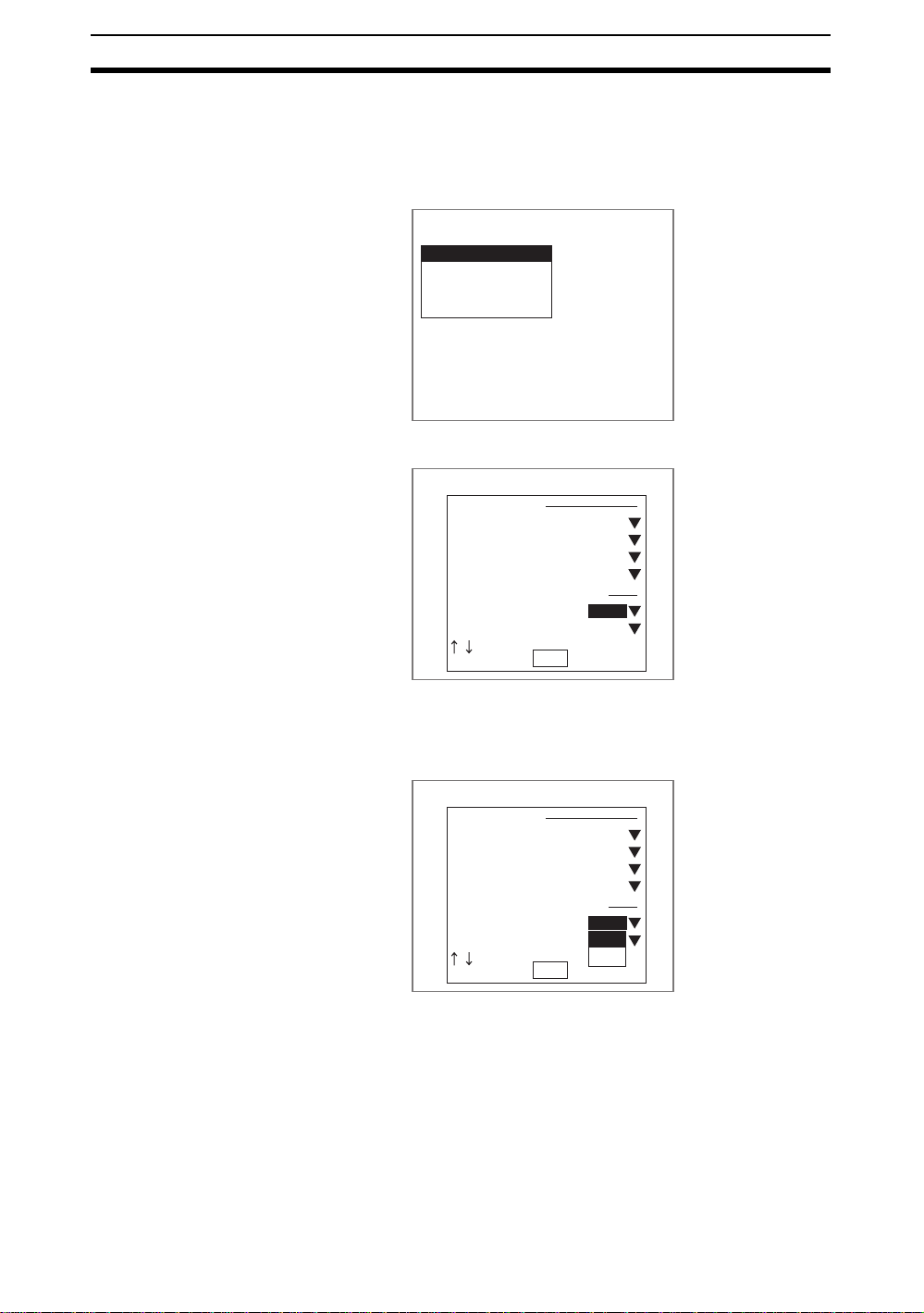
5. Select a language.
Use the Up or Down Key on the Console to move the cursor.
Japanese: Messages will be displayed in Japanese.
English: Messages will be displayed in English.
This manual shows screens displayed with English messages.
6. Press the ENT Key on the Console to confirm the language selection.
After a short time, the Basic Screen for the Setup Menus will be displayed.
Set up
Select items
Install
Backup data load
Clear memory
Precaution About the F250-UME Application Software
If the F250-UME Application Software Card is mounted to a personal computer or other device and the data changed, the Setup Menus will no longer
start properly. Never perform any of the following operations.
• Do not change file names.
• Do not move or delete files.
• Do not write data to the F250-UME Application Software Card.
• Do not format the F250-UME Application Software Card.
1-(5)
Page 14
Installing the Application Softwar e Section 1-3
1-3-2 Selecting Installation Processing Items
The F250-UME has many processing items. Select the processing items
required for the application. Refer to SECTION 2 Processing Items Setting
Procedures for an outline of each processing item.
1. Select Select items.
Set up
Select items
Install
Backup data load
Clear memory
A list of processing items will be displayed.
Select items
Input Image
Camera image
Switch camera
Change Filtering
Filtering again
Position Compensation
Binary pos. comp
Model pos. comp
End
ON
ON
ON
ON
OFF
OFF
2. Move the cursor to the item to be installed.
3. If that item is “OFF,” press the ENT Key.
The selections (ON/OFF) will be displayed.
Select Items
Input Image
Camera image
Switch camera
Change Filtering
Filtering again
Position Compensation
Binary pos. comp
Model pos. comp
End
ON
ON
ON
ON
OFF
ON
OFF
OFF
4. Select ON.
5. Repeat this process to set to ON the processing items to be installed and
set to OFF the items that are not to be installed.
6. Select END.
The settings will be registered and the screen in (1.) will return.
1-(6)
Page 15
Installing the Application Softwar e Section 1-3
1-3-3 Executing Installation
This section describes how to install the selected processing items to the Controller.
1. Select Install.
Set up
Select items
Install
Backup data load
Clear memory
A confirmation message will be displayed.
Selected Programs
will be installed.
The programs and data
stored at present
are cleared.
Execute Cancel
2. Select Execute.
The size of the p roces sing items will be calcul ated t o d etermine if the y c an
be installed.
If the total size of the se lected proc essing it ems is too larg e to be install ed,
a confirmation message will be displayed to ask if the files are to be compressed.
Total size of selected items
is too large to install.
Compressing programs make
the installation possible,
but startup time will
be longer.
Compress programs?
Execute Cancel
To STEP 3 Refer to page 1-(9).
Precaution Do not input the RESET signal or turn OFF the power supply while the pro-
cessing message is being displayed. If the RESET signal is input or the power
is turned OFF, data may be lost and the Controller may not start correctly the
next time.
A confirmation message will be displayed once the installation has been
completed.
Installation finished.
Put off the memory card
and restart.
OK
1-(7)
Page 16
Installing the Application Softwar e Section 1-3
3. Press the ENT Key.
The Main Screen for the Setup Menu will return.
Set up
Select items
Install
Backup data load
Clear memory
4. Turn OFF the power supply to the Controller.
5. Remove the F250-UME from Memory Card slot 0.
6. Turn ON the Controller power supply.
CHECK If the power is turned ON while the F250-UME is still mounted, the Setup
Menus will open. Always remove the F250-UME before turning ON the power
supply.
After a while the Camera Settings Screen will be displayed.
Camera settings
Camera :F160-S1
Intelligent Lighting 0:
Out of use
Intelligent Lighting 1:
Out of use
Intelligent Lighting 2:
Out of use
Intelligent Lighting 3:
Out of use
End
SeeAlso Refer to page SECTION 5 System Settings.
7. Select the camera to be connected.
8. If using Intelligent Lighting, select the model.
9. Select END.
The Basic Screen will be displayed.
0.Scn 0 MON
---- ---ms
1-(8)
Image 0 freeze
Page 17
Installing the Application Softwar e Section 1-3
Installation
without
Compressing
Files
If the total program size of the selected items is greater than the file size that
can be installed, a confirmation message will be displayed asking if the files
are to be compressed. If the files are compressed, the Controller startup time
will be longer. Use the following procedure to change the selected processing
items without compressing the files.
1. Select Cancel from the confirmation message.
Total size of selected items
is too large to install.
Compressing programs make
the installation possible,
but startup time will
be longer.
Compress programs?
Execute
Cancel
The program size and capacity will be displayed.
If you don't want to
compress programs,
please select items again
and make the total size
smaller than the capacity
Program size:5120KB
Capacity :3840KB
OK
2. Select OK.
The Main Screen for the Setup Menu will return.
3. Select Select items and reselect the items so that the memory capacity is
not exceeded.
SeeAlso Refer to page 1-(6).
Set up
Select items
Install
Backup data load
Clear memory
1-(9)
Page 18
Displaying Images and Focussing Section 1-4
1-4 Displaying Images and Focussing
This section explains how to check what kind of image is being displayed by
changing the display image to through display and how to adjust the position
of the measurement object and focus the camera.
1. Change the display image to through display to check what kind of image
is being displayed by pressing the SHIFT + ESC Keys.
0.Scn 0 MON
---- ---ms
Image 0 freeze
The screen for changing the display image will be displayed.
0.Scn 0
MON
Image status
Freeze(Before scroll)
Display image
Image size
Display results
End
---- ---ms
:
:Image0
: All
: None
Image 0 freeze
2. Move the cursor to Freeze (Before Scroll).
3. Press the ENT Key .
A list of options will be displayed.
1-(10)
4. Select Through.
5. Select End.
0.Scn 0
MON
Image status
Freeze(Before scroll)
Display image
Image size
Freeze (Before scroll)
Display results
Freeze(After scroll)
Last NG(Before scroll)
Last NG (After scroll)
:
:Image0
Through
: All
: Details
End
Image 0 freeze
---- ---ms
Page 19
Displaying Images and Focussing Section 1-4
The Through Display Screen will be displayed.
0.Scn 0 MON
---- ---ms
Image 0 through
6. Adjust the position of the measurement object so that it appears at the center of the monitor screen.
Adjusting the position of
the measurement object.
7. Focus the Camera.
• Cameras with a light (including Intelligent Lighting) have lenses with a
fixed focal point. Adjust the Camera position based on the positioning distances in the Setup Manual to focus the Camera.
CHECK The light level for Intelligent Lighting can be adjusted from the Controller.
Refer to page1-(31).
• When using a Camera Unit that does not have a light, turn the focus ring
to focus the Camera.
1-(11)
Page 20
Menu Operations Section 1-5
1-5 Menu Operations
1-5-1 Input Devices
Menu operation s are performed from either the Conso le or th e se rial inte rface.
F160-KP Console
ESC (escape) Key
Function Keys
F1
to
SHIFT Key
ESC
F9
F150-KP Console
SHIFT
ENT (enter) Key
ENT
SHIFT
ENT
F1
F2
F4
F5
F7
F8
Up, Down, Left, and
Right Keys (Press left,
right, up, or down.)
TRIGESC
F3
TRIG (trigger) Key
TRIG
F6
F9
ESC (escape) Key
ESC
SHIFT Key
SHIFT
TRIG (trigger) Key
TRIG
ESC TRIG
SHIFT
F150-KP
CONSOLE
ENT (enter) Key
ENT
Up, Down, Left, and
Right Keys
ENT
Key Function
ESC: Escape Key Returns the user to the previous menu display or operation.
TRIG: Trigger Key Starts object measurement.
ENT: Enter Key Execute s a fu nction or sets a value.
Note: On the F160-KP, also functions as a Cursor Key.
SHIFT Key Must be pressed in combination with another key to have any
effect. Specific functions are assigned to combinations of the
SHIFT Key and other keys for specific screens.
Up, Down, Left,
and Right Keys
The Up and Down Keys are used to move the cursor up and down
and also to set values. The Up Key will increase a value by 1 and
the Down Key will decrease a value by 1. Hold down the Up or
Down Key to quickly increase or decrease a value.
The Left and Right Keys are used to move the cursor left or right.
Function Keys Functions can be assigned to function keys F1 to F8. Refer to 5-
4-1 Changing Console Key Allocations.
The display can be captured using F9. Refer to 5-4-2 Capturing
and Saving Images.
1-(12)
CHECK Menu operations can be performed from a personal computer via a serial
interface. Refer to 6-4 Serial Interface Menu Operations.
Page 21
Menu Operations Section 1-5
1-5-2 Screen Displays
The Application Software is operated by selecting functions from menus displayed on the screen. Familiarize yourself with each function before operating
the Controller.
Scene Number
There are 32 screens. Setting
different measurement
conditions for each one allows
easy switching between
different setups.
0.Scn 0=SET=
Mode
The current operating mode is
displayed.
Cursor Keys
The cursor is moved to the
desired function by pressing
the Cursor Keys.
Units
A processing item is set for each
unit.
When a measurement command is
input, units are processed in order
from unit 0.
Mode
SET Used to set the inspection conditions.
MON (Monitor) Used to check whether inspections are being performed correctly
RUN Performs inspection. The measurement results are output to an
SYS (System) Used to set system conditions.
TOOL Used to save settings and images to a computer as backup.
SAVE Used to saves data to flash memory in the Controller. If new set-
0.Camera image
1.
ENT:Set SFT+ESC:Edit
Key Operations
Displays special key combinations at the bottom of the screen
when available.
“SFT” refers to the SHIFT Key. “SFT+ESC” indicates that the
ESC Key should be pressed while the SHIFT Key is pressed.
Sometimes the SFT Key display is abbreviated to just “S”.
Display Meaning
under the set inspection conditions. The measurement results are
displayed on the monitor only. The results cannot be output to
external devices.
external device via the parallel interface or serial interface.
tings have been made, be sure to save the data before quitting.
The type of image shown on the
screen is displayed in Monitor and
Run Modes.
Refer to 5-5-1 Displaying
Stored Images.
1-(13)
Page 22

Menu Operations Section 1-5
1-5-3 Creating Flowcharts
In the Application Software, measurement processing is broken up into different processing items to facilitate a variety of applications.
Flowchar ts are c reated usi ng a comb ination o f proces sing item s to suit e ach
application.
When Set Mode is entered, the number 1 will be displayed below 0.Camera
image. This number is calle d th e u ni t n um be r. Processing items set for t he u ni t
numbers.
0.Scn 0=SET=
0.Camera image
Unit number
CHECK “Camera image” is set for unit 0 as the default processing item.
The processing items are set in order from unit 0.
Once a processing item is set for unit 1, unit 2 will automatically be displayed.
1.
ENT:Set SFT+ESC:Edit
0.Scn 0=SET=
0.Camera image
1.EC pos. comp
2.
ENT:Set SFT+ESC:Edit
CHECK There is no limit to the number of units. Any number of units can be set pro-
vided the Controller has enough free memory.
SeeAlso Refer to SECTION 5 System Settings for information on how to check the
remaining free work memory (main memory) space.
1-(14)
Page 23
Menu Operations Section 1-5
When a measurement command is input, the processing will be executed in
order from the item set to unit 0. Register processing items for each unit, just
like creating a flowchart.
Flowchart Image
Start
0.
Read image from Camera.
1.
Perform position
displacement compensation.
2.
Inspect for defects.
3.
Output measurement result
to external device.
End
Screen Image
0.Scn 0=SET=
0.Camera image
1.EC pos. comp
2.Fine matching
3.DO judge
4.
ENT:Set SFT+ESC:Edit
1-(15)
Page 24
Menu Operations Section 1-5
The following type of processing is also possible by adjusting the registered
order.
Example: Performing Position Displacement Compensation for Two Measurement Objects in the Same Field of Vision
Flowchart Image
Start
0.
Read image from Camera.
1.
Perform position displacement
compensation for
measurement object 1.
2.
Inspect for defects on
measurement object 1.
3.
Return the image to its original
position if it has been scrolled after
position displacement compe nsat i on.
Screen Image
0.Scn 0=SET=
0.Camera image
1.EC pos. comp
2.Fine matching
3.Reset scroll
4.EC pos. comp
5.Fine matching
6.DO judge
7.
ENT:Set SFT+ESC:Edit
1-(16)
4.
Perform position displacement
compensation for measurement
object 2.
5.
Inspect for defects on
measurement object 2.
6.
Output measurement result
to external device.
End
Page 25
Menu Operations Section 1-5
The Application Software also has branch control processing items.
Example: Changing Inspection Conditions Based on the Upcoming Product
Product 2
Product 1
Flowchart Image
Start
0.
Read image from Camera.
1.
Recognize model.
2.
Change measurement
conditions based on product
type.
3.
Inspect product 1 for
defects.
4. 6.
End End
5.
Screen Image
0.Scn 0 =SET=
0.Camera image
1.Classification
2.Branch
3.Fine matching
4.End
5.Fine matching
6.End
7.
ENT:Set SFT+ESC:Edit
Inspect product2 for
defects.
1-(17)
Page 26
Menu Operations Section 1-5
play
play
eset scro
Registering
Processing
Items to Units
The registration procedure will be explained using the example of registering
binary position compensation, one of the position compensation processing
items. Change the procedure as required to register other processing items.
1. Move the cursor to a free unit number and press the ENT Key.
0.Scn 0=SET=
0.Camera image
1.
ENT:Set SFT+ESC:Edit
The processing item groups will be displayed.
0.Scn 0=SET=
0.Camera image
1.
Input Image
Position Compensation
Measurement
Measurement Support
Branch Control
Results Output
Results Dis
2. Select Position Compensation.
A list of the installed position compensation processing items will be dis-
played.
0.Scn 0=SET=
0.Camera image
1.
Input Image
Position Compensation
Binary pos. comp
Measurement
EC pos. comp
Measurement Support
Edge pos. comp
Branch Control
Model pos. comp
Results Output
Circle pos. comp
Results Dis
R
ll
3. Select Binary pos. comp.
Binary position compensation w ill be set for un it 1 and the next un it number
(unit 2 in this case) will be displayed.
0.Scn 0=SET=
0.Camera image
1.Binary pos. comp
2.
1-(18)
Page 27
Menu Operations Section 1-5
Changing to
Other
Processing
Items
1. Move the cursor to the unit number of the processing item to be changed.
Press the SHIFT+ESC Keys.
0.Scn 0=SET=
0.Camera image
1.EC pos. comp
2.Fine matching
3.
ENT:Set SFT+ESC:Edit
A list of options will be displayed.
0.Scn 0=SET=
0.Camera image
1.EC pos. comp
Change
2.Fine matching
Insert
3.
Copy
Delete
Comment
2. Select Change.
A list of processing items will be displayed.
0.Scn 0=SET=
0.Camera image
1.EC pos. comp
2.
Input Image
3.
Position Compensation
Measurement
Measurement Support
Branch Control
Results Output
Results Display
3. Use the same procedure as for registering new processing items to register a different item.
1-(19)
Page 28
Menu Operations Section 1-5
Inserting Units
CHECK When a unit is inserted, the subsequent unit numbers will be increased. The
unit numbers set in other units for outputting results and branching will also be
increased automatically.
1. Move the cursor to the unit number where a new unit is to be inserted.
Press the SHIFT+ESC Keys.
0.Scn 0=SET=
0.Camera image
1.EC pos. comp
2.Fine matching
3.
ENT:Set SFT+ESC:Edit
A list of options will be displayed.
0.Scn 0=SET=
0.Camera image
1.EC pos. comp
2.Fine matching
Change
3.
Insert
Copy
Delete
Comment
ENT:Set SFT+ESC:Edit
2. Select Insert.
A list of processing items will be displayed.
0.Scn 0=SET=
0.Camera image
1.EC pos. comp
2.Fine matching
Input Image
3.
Position Compensetion
Measurement
Measurement Support
Branch Control
Results Output
Results Display
ENT:Set SFT+ESC:Edit
3. Use the same procedure as for registering new processing items to register items for the inserted unit.
The selected processing ite m will be ins erted.
0.Scn 0=SET=
0.Camera image
1.EC pos. comp
2.EC defect
3.Fine matching
4.
1-(20)
Page 29
Menu Operations Section 1-5
Copying from
Other Units
Settings data can be copied, which is convenient for reusing data when only a
part of the settings need to be changed.
1. Move the cursor to the unit where the data to be copied is located.
Press the SHIFT+ESC Keys.
0.Scn 0=SET=
0.Camera image
1.EC pos. comp
2.Fine matching
3.
ENT:Set SFT+ESC:Edit
A list of options will be displayed.
0.Scn 0=SET=
0.Camera image
1.EC pos. comp
2.Fine matching
3.
Change
Insert
Copy
Delete
Comment
ENT:Set SFT+ESC:Edit
2. Select Copy.
A screen for selecting the source unit for the data to be copied will be dis-
played.
Original unit : Unit 0
Execute
Unit 0
Unit 1
Unit 2
3. Select the appropriate unit number.
4. Select Execute.
The data will be copied.
0.Scn 0=SET=
0.Camera image
1.EC pos. comp
2.Fine matching
3.Fine matching
4.
1-(21)
Page 30
Menu Operations Section 1-5
Deleting Units
CHECK When units are deleted, the subsequent unit numbers will be decreased. The
unit numbers set in other units for outputting results and branching will also be
reduced automatically.
1. Move the cursor to the unit to be deleted.
Press the SHIFT+ESC Keys.
0.Scn 0=SET=
0.Camera image
1.EC pos. comp
2.Fine matching
3.
ENT:Set SFT+ESC:Edit
A list of options will be displayed.
0.Scn 0=SET=
0.Camera image
1.EC pos. comp
Change
2.Fine matching
Insert
3.
Copy
Delete
Comment
ENT:Set SFT+ESC:Edit
2. Select Delete.
The selected unit will be deleted and the subsequent unit numbers will be
moved up one.
0.Scn 0=SET=
0.Camera image
1.Fine matching
2.
ENT:Set SFT+ESC:Edit
1-(22)
Page 31

Menu Operations Section 1-5
Changing
Processing Item
Names
The names of pro ce ssing items set to units ca n be changed to any name up to
16 characters long. This is a useful function for easy understanding of the settings and when setting the same processing item to many units.
1. Mov e the cu rsor to the unit f or w hich the na me of the process ing item is to
be changed. Press the SHIFT+ESC Keys.
0.Scn 0=SET=
0.Camera image
1.EC pos. comp
2.Fine matching
3.
A list of options will be displayed.
0.Scn 0=SET=
0.Camera image
1.EC pos. comp
2.Fine matching
3.
Change
Insert
Copy
Delete
Comment
ENT:Set SFT+ESC:Edit
2. Select Comment.
A software keyboard will be displayed.
Input comment
[LABEL
ABCDEFGHI J K MN
OPQRST UVWXYZ
abcdefgh i jk lmn
opqrs tuvwxyz
0123456789. #$
SPC INS END
ENT:Select
()^
%
DEL BS
]
L
!
`
-
Ins.
SeeAlso Refer to page 1-(27) for information on inputting characters.
3. Set an item name of up to 16 characters long.
4. Move the cursor to END and press the ENT Key.
The item name will be changed.
0.Scn 0=SET=
0.Camera image
1.EC pos. comp
2.Label
3.
1-(23)
Page 32

Menu Operations Section 1-5
1-5-4 Drawing a Region
Use the following method to draw model regions and measurement regions.
The region figures that can be drawn depend on the processing item. Refer to
the explanation for each processing item for information on what figures can
be drawn.
Move the cursor with the Up, Down, Left, and Right Keys. Use these keys
together with the SHIFT Key to move the cursor quickly. Press the ENT Key at
the desired positions and press the ESC Key to undo the setting.
Measurement
region selection
Box
Ellipse
The whole
region moves.
The whole
region moves.
The lower right
coordinates move.
ENT
ESC
The lower right
coordinates move.
ENT
ESC
Drawing method
ENT
The figure is set.
ENT
The figure is set.
Circle
Circumference
Polygon
The whole
region moves.
The whole
region moves.
Specify the
first point.
ENT
ESC
The circumference
changes.
ENT
ESC
Specify the
second point.
ENT
ESC
The diameter
changes.
ENT
ESC
ENT
The figure is set.
The width changes.
ENT
ESC
Specify the third
and other points.
(Up to 10 points
can be specified.)
ENT
The figure is set.
ENT
Press the ENT
Key twice.
The figure is set.
1-(24)
Page 33

Menu Operations Section 1-5
Measurement
Drawing method
region selection
Line
The whole
region moves.
ENT
The length
changes.
The width changes.
ENT
ENT
The figure is set.
Arc
The whole
region moves.
ENT
ESC
ESC
ESC
The end
point moves.
The mid-point
moves.
ENT
ESC
ESC
ENT
ESC
The width
changes.
ENT
The
figure
is set.
Drawing Mode For many processing items, up to 3 figures can be combined to draw a mea-
surement region. Select either the OR or NOT drawing mode.
Drawing
mode
OR Us e this mode to draw a shape as a model or measurement region.
All of the shapes that are drawn are registered as one region.
NOT Use to delete part of a region.
Function
In this example, the gray area will be the measurement region.
Regions with complicated shapes can be drawn and areas can be omitted
from the measurement region b y co mbi ni ng figu res.
Figure 1 (drawn using OR)
Figure 2 (drawn using NOT)
Figure 3 (drawn using OR)
1-(25)
Page 34

Menu Operations Section 1-5
y
1-5-5 Inputting Values
This section explains how to input values when setting measurement conditions or communications specifications.
1. Move the cursor to the item for which a value is to be changed.
Judgement conditions
Area : 2035.000
[ 2000.000 : 247808.000]
Gravity X : 180.000
[ 0.000 : 511.000]
Gravity Y : 250.000
[ 0.000 : 483.000]
End
2. Press the ENT Key.
The cursor will change to a cursor the size of a single digit.
Judgement conditions
Area : 2035.000
[ 2000.000 : 0247808.000]
Gravity X : 180.000
[ 0.000 : 511.000]
Gravity Y : 250.000
[ 0.000 : 483.000]
End
3. Move the cursor to the digit to be changed.
Use the Left and Right Keys to move the cursor.
4. Change the val ue.
Use the Up Key to increase the value.
Use the Down Key to decrease the value.
Judgement conditions
Area : 2035.000
[ 2000.000 : 0047808.000]
Gravity X : 180.000
[ 0.000 : 511.000]
Gravit
Y : 250.000
0
5. Repeat these steps to change other values.
6. Press the ENT Key .
The values will be set.
Judgement conditions
Area : 2035.000
[ 2000.000 : 25000.000]
Gravity X : 180.000
[ 0.000 : 511.000]
Gravity Y : 250.000
[ 0.000 : 483.000]
End
1-(26)
Page 35

Menu Operations Section 1-5
1-5-6 Inputting Characters
This section explains how to input characters. The software keyboard shown
below is displayed on the screen where characters are input.
ABCDEFGHI J K MN
OPQRSTUVWXYZ
abcdefgh i jk lmn
opqrs tuvwxyz
0123456789. #$
SPC
%
DEL
()^
BSBSINS
`
L
!
-
END
1. Move the cursor to the character to be input.
cursor Cursor
[
ABCDEFGHI J K MN
OPQRSTUVWXYZ
abcdefgh i jk lmn
opqrs tuvwxyz
0123456789. %
#$
SPC DEL BS INS
2. Press the ENT Key.
The character is set and the I cursor moves one space to the right.
These characters can be input.
Inserts a space.
SPC
Deletes 1character to the right of the I cursor.
DEL
Deletes 1character to the left of the I cursor.
Switches between insert (default)/overwrite.
INS
Moves the I cursor to the left.
Moves the I cursor to the right.
Ends character input.
END
]
L
()^
`
←→
!
END
3. Repeat these steps to in put more characters.
4. Once all required characters have been input, move the cursor to END.
()^
%
DEL BS
]
L
!
`
←→
-
END
Ins.
[LABEL
ABCDEFGHI J K MN
OPQRSTUVWXYZ
abcdefgh i jk lmn
opqrs tuvwxyz
0123456789. #$
SPC INS
ENT:Select
5. Press the ENT Key .
The characters will be set.
CHECK Characters can be input from a personal computer via a serial interface. Refer
to 6.4 Serial Interface (Menu Ope r atio ns ).
1-(27)
Page 36

Basic Operations Section 1-6
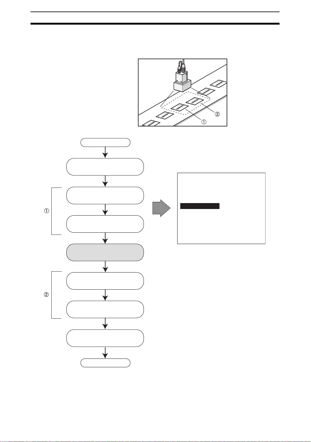
1-6 Basic Operations
This section describes the basic flow of operations up to the setting of measurement conditions and executing measurements. The explanation is based
on the use of the Fine Matching proc essi ng item f o r the meas uremen t method .
Detecting Label Defects
0.Scn0 RUN
Minor defect
step
1
step
2
step
3
step
4
NG
Pattern defects
Edge defect
Settings for image input
Settings for position
displacement compensation
of measurement object
Setting measurement method
Settings for measurement
result output method
Printing defect
1-(28)
step
5
Start test or measurement.
Page 37

Basic Operations Section 1-6
1-6-1 STEP 1: Settings for Image Input
To set the inspection conditions, change first to Set Mode.
When Set Mode is entered, th e de fault processing ite m for unit 0 will be “Cam-
era image.” The conditions for inputting images are set under this processing
item.
1. Display the Bas ic Screen and m ov e th e curs or to MON and press the ENT
Key.
0.Scn 0 MON
SET
MON
RUN
SYS
TOOL
SAVE
---- ---ms
Image 0 freeze
2. Select SET.
The initial screen for Set Mode will be displayed.
Camera Image is the default processing item for unit 0.
0.Scn 0=SET=
0.Camera image
1.
ENT:Set SFT+ESC:Edit
3. Select 0. Camera image.
The initial screen for Camera Image will be displayed.
0.Camera image
Camera settings
Select camera
Filtering order(Image0)
Filtering(Image0)
BGS levels(Image0)
Filtering order(Image1)
Filtering(Image1)
BGS levels(Image1)
Frame/Field
1-(29)
Page 38

Basic Operations Section 1-6
The items that can be set under Camera Image can be broadly classified into
three groups:
• The shutter speed and other conditions relating to when t he i ma ge i s c ap tured (camera settings).
• Selection of which camera image will be measured (camera s election).
• Settings to make the image easier to measure (filtering).
Camera Image
Camera
settings
Camera
0
Camera
1
Camera
2
Camera
3
Image buffer
(for Camera 0)
Image buffer
(for Camera 1)
Image buffer
(for Camera 2)
Image buffer
(for Camera 3)
Camera
selection
* Only one camera can be selected.
Filtering
0
Filtering
1
Image 0
Image 1
The Controller has two image memories. Two images, Image 0 and Image 1,
are stored for the camera image selected under Select Camera. Both images
are for the same Camera but different filtering can be applied to each of the
images.
Some processing items require selection of either Image 0 or Image 1 for
object measurement and other processing items me asure only Image 0. Refe r
to the explanations for each item for details.
In this section wh ere the e xam ple o f Fine M atchi ng is used, meas uremen ts w ill
be performed on Image 0.
1-6-1-1 Camera Settings
Shutter Speed Change the shutter speed when the object is moving quickly, causing the
For F150-S1A Cameras
Object movement
Slow
Fast
image to be blurred.
The shutter speed can be changed from the menu for F150-S1A and F160-S1
Cameras only.
For F160-S1 Cameras
Shutter speed
1/100 s
1/500 s
1/2000 s
1/10000 s
(Default setting: 1/2000 s)
Object movement
Slow
Fast
Shutter speed
1/120 s
1/200 s
1/500 s
1/1000 s
1/2000 s
1/4000 s
1/8000 s
1/20000 s
(Default setting: 1/2000 s)
1-(30)
Page 39

Basic Operations Section 1-6
0s
00s
500s
000s
000s
000s
8000s
0000s
1. Select Camera settings.
0.Camera image
Camera settings
Select camera
Filtering order(Image0)
Filtering(Image0)
BGS levels(Image0)
Filtering order(Image1)
Filtering(Image1)
BGS levels(Image1)
Frame/Field
The initial Camera Settings Screen will be displayed.
Camera settings
Shutter speed(Cam0)
Light control(Cam0)
Calibration(Cam0)
Shutter speed(Cam1)
Light control(Cam1)
Calibration(Cam1)
Shutter speed(Cam2)
Light control(Cam2)
2. Select Shutter speed for the Camera to be used.
The shutter speed selections will be displayed.
Shutter speed(Camera0)
1/ 12
1/ 2
1/
1/ 1
1/ 2
1/ 4
1/
1/2
3. Select the shutter speed while monitoring the image.
4. Press the ENT Key .
The setting will be registered and the screen in (1.) will return.
Light Control When using Cameras with Intelligent Lighting, the light level can be adjusted
from the Co ntroller. Before using Inte lligent Lighting , be sure to change the
settings in SYS/Camera settings.
SeeAlso Refer to 5-2 Camera Settings.
CHECK When the shutter speed is faster than 1/2000 s, the brightness of the lighting
may not change even if the light level is changed.
Intelligent lighting uses pulse lighting synchronized with the shutter speed and
the light level can be adjusted by changing the pulse width. If the light level is
at the maximum setting of 7, the pulse width is approximately 450 ms and the
time the shutter is open is about the same as when the shutter speed is set to
1/2000 s. This means that settings will become invalid (the brightness will not
1-(31)
Page 40

Basic Operations Section 1-6
change) if the shutter speed is f aster tha n 1/20 00 s and the light le vel setting is
high.
Example: When Shutter Speed is 1/4000 s, Light Level Adjusted to 4
Light level: 7 (Approx. 450ms max.)
Light level: 4
(Approx. 260 ms max.)
Flash
Shutter
■ Lighting Control Screen
Light level adjustment:
Enabled
Light level adjustment:
Disabled
B. Light level
Light control(Camera 0)
Lighting pattern 1 50000
A. Segment displays
C. Sample lighting pattern number
A. Segment Display
As viewed from
this perspective
F150-LTC20
F160-LTC20
B
A
E
C
D
Lighting can be adjusted
for 5 areas.
F150-LTC50
F160-LTC50
E
A
DH
BF
C
G
Lighting can be adjusted
for 8 areas.
CHECK The lit segments are di spl ayed wit h thi ck lines. The b right ne ss dep end s o n the
set light level. Refer to page 1-(33).
Segment A level
Segment B level
1-(32)
B. Light Levels
The light level for each segment is displayed in a 5- or 8-digit value, with each
digit representing the light level of one of the segments. The light levels are
displayed from 0 to 7 , wi th 0 indicating that the light is OFF. The hi ghe r th e setting, the higher the light level.
F150-LTC20
F160-LTC20
3 3 3 3 3
Segment C level
Segment E level
Segment D level
Segment A level
Segment B level
Segment C level
Segment D level
F150-LTC50
F160-LTC50
3 3 3 3 3 3 3 3
Segment H level
Segment G level
Segment F level
Segment E level
C. Number of Sample Lighting Patterns
There are 15 sample lighting patterns registered in advance.
Page 41

Basic Operations Section 1-6
00004444
00007777
70707070
■ Adjustment Method 1: Sample Lighting Patterns
There are 15 lighting patterns registered in advance. The lighting can be set
simply by going through the different patterns in order and selecting the one
that gives the clearest image. Use the SHIFT+Left and Right Keys to switch
between sample patterns.
F150-LTC20, F160-LTC20
■ Not lit
@ Lit (maximum light level)
Pattern
LIght level Pattern
No.
1 4 7 10 13
50000
Light level Pattern
No.
07070 22727 00070 52222
Light level Pattern
No.
Light level Pattern
No.
Light level
No.
2 5 8 11 14
3 6 9 12 15
03333 27272 07000 00007 17777
07777 00707 00700 51111 27777
F150-LTC50, F160-LTC50
Pattern
Light level Pattern
No.
1471013
77777777
2581114
44440000
3691215
77770000
Light level Pattern
No.
Light level Pattern
No.
07070707
70000000
07000000
Light level Pattern
No.
00700000
00070000
00007000
Light level
No.
00000700
00000070
00000007
1-(33)
Page 42

Basic Operations Section 1-6
■ Adjustment Method 2: Adjusting Light Levels by Segment
The light level for each segment can be set separately to a value between 0
and 7. The setting “0” represents the unlit state, and the higher the setting
value the higher the light level. Light levels can also be set by adjusting the
light levels for the segments separately after selecting a sample lighting pattern.
Use the Left and RightKeys to select the segment to be adjusted and use the
Up and Down Keys to adjust the light level.
F150-LTC20, F160-LTC20
F150-LTC50, F160-LTC50
1. Select Camera settings.
0.Camera image
Camera settings
Select camera
Filtering order(Image0)
Filtering(Image0)
BGS levels(Image0)
Filtering order(Image1)
Filtering(Image1)
BGS levels(Image1)
Frame/Field
1-(34)
The initial Camera Settings Screen will be displayed.
Camera settings
Shutter speed(Cam0)
Light control(Cam0)
Calibration(Cam0)
Shutter speed(Cam1)
Light control(Cam1)
Calibration(Cam1)
Shutter speed(Cam2)
Light control(Cam2)
2. Select Light control for the Camera number being used.
Page 43

Basic Operations Section 1-6
The Light Control Settings Screen will be displayed.
Light control(Camera0)
Lighting pattern5:27272
SFT+ :Sample
:Segment :Light volume
Graphic showing light level
3. Switch the s ampl e patt ern light ing l e v el using the SHIFT+Left/Right Keys.
CHECK For fine adjustment of light levels, move to the desired segment using the
Right and Left Keys and adjust the light level using the Up and Down Keys.
4. Press the ENT Key.
The setting will be registered and the screen in (1.) will return.
CHECK If all light adjustments are set to 5 or higher, there may be insufficient light
emitted if the distance between measurements is approximately 15 ms or less.
If this happens, set the light level to 4 or less.
Calibration Calibration can be set to output the measurement results in physical units.
Set the relationship between the physical coordinates and the camera coordinates to convert the measurement results from pixels to physical units, such
as mm, mm, or cm.
This section gives an outline only. Refer to 2-1 Inputting Camera Images for
details on calibration.
CHECK To output measurem ent res ults in physical units, set Coordinate mode/Calibra-
tion to ON for each processing item.
If Calibration remains set to OFF, the default settings will remain, and mea-
surements using the Camera coordinates will be output.
1-6-1-2 Selecting the Camera
Up to 4 Cameras can be connected. The Select Camera setting is used to
select the Camera image that will be used for measurement.
CHECK The Camera image selected here will be used for all subsequent unit mea-
surements. To switch to a different Camera part way through processing, use
the Switch Camera processing item. Other Camera images stored in the
image buffers can be imported to Image 0 and Image 1.
0.Scn 0=SET=
0.Camera image
1.Density defect
2.Binary defect
3.Fine matching
4.Switch camera
5.Density defect
6Binary defect
The Camera image selected at
0. Camera image will be used
for measurement.
The Camera image selected
using 4. Switch camerawill be
used for measurement.
1-(35)
Page 44

Basic Operations Section 1-6
Note Switch camera only switches between the images saved to Image 0 and
Image 1 from the image b uff e rs . Ne w imag es can not be se nt to the i mage b uff ers using th is processing item.
1. Select Select camera.
0.Camera image
Camera settings
Select camera
Filtering order(Image0)
Filtering(Image0)
BGS levels(Image0)
Filtering order(Image1)
Filtering(Image1)
BGS levels(Image1)
Frame/Field
A list of Camera numbers will be displayed.
Select camera
Camera 0
Camera 1
Camera 2
Camera 3
2. Select the number of the Camera to be used.
3. Press the ENT Key.
The setting will be registered and the screen in (1.) will return.
1-6-1-3 Filtering
The image read by the Camera can be manipulated to create an image that is
easier to measure. Image filtering is set by using 3 functions: Filtering Order,
Filteri ng, and BGS Levels.
0.Camera image
Camera settings
Select camera
Filtering order(Image0)
Filtering(Image0)
BGS levels(Image0)
Filtering order(Image1)
Filtering(Image1)
BGS levels(Image1)
Frame/Field
The Controller has tw o i ma ge memories, and Filte ring, BG S L evels, and Filtering Order can be set for each.
This section gives an outline only. Refer to 2-1 Inputting Camera Images for
details on filtering.
1-(36)
Page 45

Basic Operations Section 1-6
1-6-1-4 Frame/Field
The Frame/Field function is used to select the unit for one image. Normally, it
is sufficient to use the default setting of Frame.
If the unit is changed to Field, the resolution in the vertical direction is halved
but the image input time is reduced, allowing faster processing.
Field images
Even Odd
Images showing alternate fields
Resolution: 512 × 242 (H × V) Resolution: 512 × 242 (H × V)
One frame image is created when
two field images are combined.
Frame image
Resolution: 512 × 484 (H × V)
This section gives an outline only. Refer to 2-1 Inputting Camera Images for
details on Frame/Field.
1-(37)
Page 46

Basic Operations Section 1-6
1-6-2 STEP 2: Settings for Posi tion Di splacement Compensation
The position displacement compensation processing items are used when the
position and orientation of measurement objects are not consistent. By using
this function, the displacement between a reference position and the current
position is obtained, and this displacement is compensated for in measurements.
Select the position compensation processing items suitable for the measurement object.
Reference Position
The reference po s it ion i s us ed so tha t t h e me a su r em en t r e gi on an d me a su rement object are in the correct positions.
Measurement region
Measurement object
1-(38)
Page 47

Basic Operations Section 1-6
Measurement Object Displ ace d
Without compensation, measurement is
performed with part of the measurement
object outside the measurement region.
By making position displacement compensation settings...
Measurement is performed after the
image is returned to the reference
position.
In either case, measurement is performed with
the whole measurement object in the
measurement region.
Measurement is performed after the
measurement region is moved to
compensate for the displacement.
1-(39)
Page 48

Basic Operations Section 1-6
1-6-3 STEP 3: Setting Measurement Methods
This section describes how to inspect for defects using the F ine Matching processing item.
The registered image for an acceptable product and the input image are overlaid (matched) and the differences are detected. This enables small defects in
the pattern and wr iti ng on t he me asu rem ent obj ect t o b e de tect ed w ith a hi gh
level of accuracy.
OK Image
(registered)
Images overlaid
Defects are displayed using the NG
color. Defects are judged b y the area of
difference from the OK image.
0.Scn 0 MON
Image to be
inspected
NG
Pattern defect
Minute defect
Edge defect
Printing error
Use the following procedure to set Fine Matching for unit 1.
1. Move the cursor to unit 1 and press the ENT Key.
0.Scn 0=SET=
0.Camera image
1.
ENT:Set SFT+ESC:Edit
1-(40)
Page 49

Basic Operations Section 1-6
The processing item groups will be displayed.
0.Scn 0=SET=
0.Camera image
1.
Input Image
Position Compensation
Measurement
Measurement Support
Branch Control
Results Output
Results Display
ENT:Set SFT+ESC:Edit
2. Select Measurement.
A list of processing items will be displayed.
0.Scn 0=SET=
0.Camera image
1.
Input Image
Position Compensation
Measurement
Measurement Support
Branch Control
Results Output
Results Display
ENT:Set SFT+ESC:Edit
3. Select Fine matching.
Fine Matching will be set for unit 1.
CHECK If processing items are set for units after the unit to which Fine Matching has
been set, care must be taken when manipulating images. Refer to page 1(57).
Operational Flow
(As required) (As required) (As required) (As required)
1 3 4 6 7 85
Select the
method for
matching with
the model.
2
Change the
labeling
conditions.
Register the
model.
Set the
judgement
conditions.
Binary defect
Classification
Density defect
EC defect
ECM search
EC position
Edge position
Fine matching
Change the
differential
judgement
value.
Change the
detailed
conditions.
Set the
coordinate
mode.
Reference
the model.
1-(41)
Page 50

Basic Operations Section 1-6
1-6-3-1 Selecting the Method for Matching with Model
This section describes how to select a matching method suitable for the measurement object.
Measurement conditions
Boundary inspection:
Defect inspection :
Target :
End
Use the following as a guide for selection:
To detect patter n
defects
To detect minute
defects
ON
Labeling
Both
(Choose the most stable method.)
For the fastest
inspections
When there are
defects near the edge
of the measurement
object
Color for defects (Both*, white, black)
Processing time is reduced if either white or black
is selected when the defect color is consistent.
The asterisk (*) indicates the default setting.
Boundary inspection: ON
Defect inspection: Labeling
Boundary inspection: ON
Defect inspection: Binary
Boundary inspection: OFF
Defect inspection: Labeling
Boundary inspection: ON
Defect inspection: Labeling
1-(42)
HELP Refer to page 1-(43) for inf o rmation on bou ndary inspec tion an d defect inspec-
tion methods.
1. Select Fine matching.
0.Scn 0=SET=
0.Camera image
1.Fine matching
2.
ENT:Set SFT+ESC:Edit
Page 51

Basic Operations Section 1-6
The initia l screen for fine matching will be displayed.
Measurement conditions
Labeling
Model registration
Judgement conditions
Differencial image
Detailed conditions
Coordinate mode
Model reference
2. Select Measurement conditions.
The Measurement Conditions Settings Screen will be displayed.
Measurement conditions
3. Make the settings for each item.
4. Select End.
The setting will be registered and the screen in (1.) will return.
HELP Boundary Inspections
Boundary inspections match the boundary areas (areas where the density
changes).
•OFF
This method masks the boundary, excluding it from inspection. This
means that any defects near the boundary will not be detected. The
boundary level sets the number of pixels near the boundary that will be
excluded from the inspection.
SeeAlso See page 1-(53).
Boundary inspection:
Defect inspection :
Target :
Model Inspection image
1 square = 1 pixel
Labeling
End
ON
Both
If the measurement object is
displaced slightly higher, the
boundary will be detected as
differing from the registered
model.
When Boundary inspection is
OFF: The range of pixels set
for the boundary level are
excluded from the
measurement on both sides of
the boundary.
•ON*
The whole area is inspected and defects near the boundary will be
detected. The processing time, however, will be longer because eroded
and dilated mode ls are match ed t o pre vent inspection m ista k es ca used by
measurement object displacement. Only defects detected for both models
will be judged as d ef e cts . The s iz e of di lation and ero sion c an be set us ing
the boundary level.
The asterisk (*) indicates the default setting.
1-(43)
Page 52

Basic Operations Section 1-6
SeeAlso
See page 1-(53).
Dilated Model
Example: Dilation by 3
pixels when the boundary
level is set to 3.
HELP Defect Inspection Methods
An image showing the difference between the model image and inspection
image will be converted internally to a binary image. The method for inspecting defects from those binary images is selected here.
• Labeling*
One group of white pixels is detected as one label and one label that
matches th e set co nditions will b e evaluated to d eter mine if it is a defect
or not.
The asterisk (*) indicates the default setting.
• Binary
The total area of the white pixels is evaluated to determine if there are
defects or not.
Eroded Model
Example: Erosion by 3
pixels when the boundary
level is set to 3.
One defect (max. area)
One defect
One defect
Total area of white pixels
1-(44)
Page 53

Basic Operations Section 1-6
1-6-3-2 Changing Labeling Conditions
When Labeling area is selected as the defect inspection method, the following
labeling conditions can be changed to match the inspection goals.
Labeling
Area :
Area range for labels (0 to 9,999,999.999 (0 to 247,808.000*))
[ 0.000 : 247808.000 ]
Sort :
Area descending order
Label No. :[ 0]
Label number for which to inspect for defects (0 to 999 (0*))
End
Conditions for reassigning label numbers
Area descending order:*
Area ascending:
Gravity X descending:
Gravity X ascending:
Gravity Y descending:
Gravity Y ascending:
Sorts in descending order by area.
Sorts in ascending order by area.
Sorts in descending order by center of gravity X coordinate. (See note.)
Sorts in ascending order by center of gravity X coordinate. (See note.)
Sorts in descending order by center of gravity Y coordinate. (See note.)
Sorts in ascending order by center of gravity Y coordinate. (See note.)
The asterisk (*) indicates the default setting.
Note When X and Y center of gravity are sorted, the upper left corner of the screen is the origin.
The coordinate system set under
0
Y
Sort example:
Labeling result
X
calibration will not be affected.
Label numbers in
descending order
by area
Label numbers in
ascending order by
X center of gravity
0
Label numbers in
descending order by
Y center of gravity
2
1
220
11
1. Select Labeling.
0
1.Fine matching
Measurement conditions
Labeling
Model registration
Judgement conditions
Differencial image
Detailed conditions
Coordinate mode
Model reference
1-(45)
Page 54

Basic Operations Section 1-6
The Labeli ng Conditions Settings Screen will be displayed.
Labeling
Area :
[ 0.000 : 247808.000 ]
Sort :
Area descending order
Label No. :[ 0]
End
SeeAlso Refer to page 1-(26) for information on inputting values.
2. Change the se ttings.
3. Select End.
The settings will be registered and the screen in (1.) will return.
1-6-3-3 Registering Models
An image of an acceptable product is registered as the model. The image of
the measurement object read by the Camera is compared with this model and
defects are detected where there are differences from the model.
CHECK The image stored to Image 0 is used as the measurement image for Fine
Matching.
CHECK The model registration range is (6,6) to (505,477).
If pre-processing (filtering) is set for the measurement image, the range that
can be registered will be reduced further.
Screen size
512 pixels
Registration range:
(6,6) to (505,477)
484
pixels
Filter size of 5
-
2 pixels
Registration range:
(8,8) to (503,475)
5
Filter size of 3
-
1 pixel
Registration range:
(7,7) to (504,476)
3
1-(46)
Page 55

Basic Operations Section 1-6
1. Select Model registration.
1.Fine matching
Measurement conditions
Labeling
Model registration
Judgement conditions
Differencial image
Detailed conditions
Coordinate mode
Model reference
The Model Registration Screen will be displayed.
Model registration
New
Box
End
OR
Ellipse
NOT
Circle
Circumference
Polygon
SeeAlso Refer to page 1-(24) for methods for drawing regions.
2. Select New.
3. Select the de sired figure.
4. Select the desired drawing mode (OR/NOT).
An arrow cursor will appear.
Up to three figures (0, 1, and 2)
can be drawn.
Model registration
[0]
492,405
5. Draw the region to be registered as the model with the selected figure.
CHECK The range that can be registered as a model is (6,6) to (505,477).
1-(47)
Page 56

Basic Operations Section 1-6
The figure will be registered.
Once three figures have been drawn,
Add will no longer be displayed.
Model registration
Add
Figure0
End
6. If additional figures are to be drawn, select Add.
7. Repeat steps 3 to 5 as necessary to create the desired shape.
8. After drawing is completed, select End.
The measurement region will be registered and the screen in (1.) will re-
turn. The model region will be displayed.
CHECK Figures drawn using O R mode are displa yed with solid lines and figures dr a wn
using NOT mode are displayed with dotted lines.
Figure 1 (drawn using OR)
Figure 2 (drawn using NOT)
Figure 3 (drawn using OR)
CHECK Set the model region so that no more than three areas lie along any one
straight line.
INCORRECT
Rectangle (drawn using OR)
Circumference (drawn using NOT)
Circle (drawn using NOT)
3
2
1
4
1-(48)
Page 57

Basic Operations Section 1-6
Correcting or
Clearing Figures
1. In the screen for step 5 above, select the figure to be changed or cleared
using the Up and Down Keys and press the ENT Key.
Model registration
Add
Figure0
Figure1
End
The figure f or the figu re number s elected us ing the c ursor will be d ispla y ed
with solid lines. The selections Correct and Clear will be displayed.
2. Select either Correct or Clear and press the ENT Key.
If Correct is selected, the cursor will be displa ye d. Correct the size and po -
sition of the figure as desired.
If Clear is selected, the selected figure will be cleared.
1-6-3-4 Setting the Judgement Conditions
Make the setting for number of labels, area, and center of gravity.
Range for an OK judgement
Judgement conditions
Quantity
Area
[ 0.000 : 247808.000]
Gravity X
[ 0.000 : 511.000]
Gravity Y
[ 0.000 : 483.000]
:
0 [ 0: 0]
:
123.152
:
100
:
100
End
Range for number of labels (0 to 1,000)
(The total white pixel area is counted as one label
when defect inspection is set to Binary.)
Area range (0 to 9,999,999.999)*
X axis movement range (-9,999.999 to 9,999.999)*
Y axis movement range (-9,999.999 to 9,999.999)*
* When the defect inspection is set to Labeling,
these settings are the judgement conditions for
the specified label number.
Figure 1 Figure 0
Correct
Clear
Measurement results for the displayed image
:
Use these values as a ref erence for setting upper and lower limits.
1. Select Judgement conditions.
1.Fine matching
Measurement conditions
Labeling
Model registration
Judgement conditions
Differencial image
Detailed conditions
Coordinate mode
Model reference
1-(49)
Page 58

Basic Operations Section 1-6
The settings screen will be displayed.
Judgement conditions
Quantity
Area
[ 0.000 : 247808.000]
Gravity X
[ 0.000 : 511.000]
Gravity Y
[ 0.000 : 483.000]
:
0 [ 0: 0]
:
123.152
:
100
:
100
End
SeeAlso Refer to page 1-(26) for information on inputting values.
2. Make the settings for each item.
3. Select End.
The judgement condition settings will be registered and the screen in (1.)
will return.
1-6-3-5 Changing Differential Judgements as Required
Differential judgement values use the basic gradation of the differences
between the model and measurement object images. Differential judgement
values can be set between 1 and 255. Pixels in areas with a difference greater
than the differential judgement value are converted to 1 (white) and all other
pixels are converted to 0 (blac k). Thu s , only the de fects are converted to white
pixels and are measured.
The default differential judgement value of 50 is usually sufficient, but change
this value if the defects are not being detected properly.
Model image Inspection image
1-(50)
Overlaid
Pixels in areas with a differential
greater than the differential judgement
value are converted to 1 (white).
All other pixels (no difference to
model) are converted to 0 (black).
Page 59

Basic Operations Section 1-6
1. Displa y the ima ge of an NG obj ect to enab le the di ff erential judgemen t val ue to be adjusted while looking at the differential image.
1.Fine matching
Measurement conditions
Labeling
Model registration
Judgement conditions
Differential image
Detailed conditions
Coordinate mode
Model reference
2. Select Differential image
The settings screen will be displayed.
The differential image will be shown within the model registration region.
The rest of the screen will be black.
Differential image
(Black)
Difference:[ 50]
OK
SFT+ :Switch image
Model registration
region
CHECK There are two differential images, one showing only black defects and the
other showing only white defects. The differential value can be set separately
for each.
Example:
Black defects
(Black marks when compared to model image)
White defects
(White marks when compared with model image)
1-(51)
Page 60

Basic Operations Section 1-6
3. Use the SHIFT+Left and SHIFT+Right Keys to switch between the white
defect and black defect images.
Differential image
(White)
SFT+ :Switch image
Difference:[ 50]
OK
4. Move the cursor to the differential value (difference) and use the Left and
Right Keys to change the value.
Change the value until the defect is displayed in white.
Right Key: Increases the value by 1.
Left Key: Decreases the value by 1.
Repeat the abov e two ste ps to adjus t the diff erentia l value f or the other image.
5. Select OK.
The settings will be registered and the screen in (1.) will return.
1-6-3-6 Changing Detailed Conditions as Required
Change the detailed conditions if required when matching is not stable.
1. Select Detailed conditions.
1.Fine matching
Measurement conditions
Labeling
Model registration
Judgement conditions
Differencial image
Detailed conditions
Coordinate mode
Model reference
The Detailed Conditions Settings Screen will be displayed.
Detailed conditions
Boundary level
Perturbation
Normalization
Defect display
End
:
:
:
:
[3]LVL
OFF
OFF
Simple
SeeAlso Refer to page 1-(26) for information on inputting values.
2. Make the settings for each item.
Refer to the next page for details.
1-(52)
Page 61

Basic Operations Section 1-6
3. Select End.
The detailed condition s settings will be re gistered and the sc reen in (1.) will
return.
CHECK Re-register the model if the edge level has been changed.
Boundary Level Select the extent to which the boundary difference (change in density) will be
absorbed. Set a value between 1 and 5 (3*). The usage of the boundary level
setting depends on the settin g f o r the Boun dary Inspecti on. Refer to the following information f or deta ils .
The asterisk (*) indicates the default setting.
SeeAlso See page 1-(43).
CHECK Re-register the model if the boundary level has been changed.
Perturbation Select whether or not to perform a search near the registered model position.
Density
Normalization
This function can be set to OFF* or ON. If OFF is selected, matching is performed only at the registered position, which reduces processing time.
The asterisk (*) indicates the default setting.
ON OFF
3 pixels
3 pixels
Matching performed for the
registered model position
and surrounding area.
4 pixels
4 pixels
Matching performed for
registered model position only.
This function is used to select whether or not to normalize the density in line
with the brightness of the registered model. The selections are OFF* and ON.
The asterisk (*) indicates the default setting.
If ON is selected, matching is performed after the density is compensated,
even if the overall brightness of the image has changed. This means that the
measurement is less likely to be affected by lighting variations.
Model image Inspection image
(Darker overall)
Normalization
1-(53)
Page 62

Basic Operations Section 1-6
Defect Display This function is used to select the display method for defects or burrs.
The display will change depending on the settings for the defect inspection.
SeeAlso See page 1-(44).
Selection Defect
inspection
method
Simple* Labeling
Defect display position
The cursor will be
displayed at the center
of the set label.
Binary
Detail Labeling
Binary
The asterisk (*) indicates the default setting.
The cursor will be
displayed at the center
of gravity of the defects.
If there is more than one
defect, the cursor will be
displayed at the center
of the white pixels, so it
may not be on a defect.
The set label will be
displayed in the NG
color.
All defects will be
displayed in the NG
color.
1-(54)
Page 63

Basic Operations Section 1-6
1-6-3-7 Setting the Coordinate Mode
When outputting the defect position coordinates, select the type of coordinates.
Coordinate mode
Before scroll:Output made using the coordinate values before
After scroll*: Output made using the coordinate values after
position displacement compensation
position displacement compensation
Output coordinate:
After scroll
Calibration : OFF
End
The asterisk (*) indicates the default setting.
Refer to 7-4 Terminology for differences between
output coordinates.
ON: Output made using coordinate values set using calibration
OFF*: Output made using Camera coordinate values
CHECK If the coordinate mode is changed after the judgement conditions have been
set, the measurement results will change also. Change the judgement conditions to enable correct measurement.
1. Select Coordinate mode.
1.Fine matching
Measurement conditions
Labeling
Model registration
Judgement conditions
Differencial image
Detailed conditions
Coordinate mode
Model reference
The Coordinate Mode Settings Screen will be displayed.
Coordinate mode
Output coordinate:
After scroll
Calibration : OFF
End
2. Make the settings for each item.
3. Select End.
The settings will be registered and the screen in (1.) will return.
1-(55)
Page 64

Basic Operations Section 1-6
1-6-3-8 Referencing Models
Models can be displayed on screen to check what kind of images are registered as models.
1. Select Model reference.
1.Fine matching
Measurement conditions
Labeling
Model registration
Judgement conditions
Differencial image
Detailed conditions
Coordinate mode
Model reference
The image that is registered as the model will be displayed.
Model reference
ESC:End
2. Press the ESC Key.
The screen in (1.) will return.
1-(56)
Page 65

Basic Operations Section 1-6
HELP
Handling Images for Fine Matching
When Fine Matching is executed, the differential image (where only the differ-
ence between the model and inspection images has been extracted) is stored
as Image 1.
If Image 1 is to be used for measurement for subsequent un its, set Cha nge Fil -
tering before the next processing item and obtain the image stored in the
image buffer again.
Fine matching uses Image 0 for
measurement
Camera
setting
Camera
0
Camera
1
Camera
2
Camera
3
Image buffer
(for Camera 0)
Image buffer
(for Camera 1)
Image buffer
(for Camera 2)
Image buffer
(for Camera 3)
Camera
selection
Filter
0
Filter
1
Image 0
Image 1
The differential image is stored
after fine matching is executed.
Setting Example
0.Scn 0=SET=
0.Camera image
1.Fine matching
2.Change Filtering
3.Binary defect
Image 1 to be used for
measurement
Image obtained again from image buffer
1-(57)
Page 66

Basic Operations Section 1-6
1-6-4 STEP 4: Setting Results Output Methods
This function is used to set the method for outputting measurement results to
an external device.
When measurement is executed, the overall judgement (OK or NG) for the set
data is output to the parallel interface OR signal.
Only results from measurements performed in Run Mode will be output.
Results of measurements executed in Monitor Mode will not be output to an
external device.
Set the processing items for the desired results output as outlined in the following table.
Data to be output Appropriate
Judgement (OK or NG) output via a parallel interface DO Judgement
Measurement output via a parallel interface DO Data
Measurement in normal format output via a serial interface Normal Data
Measurement in Host Link format output via a serial interface Host Link Data
Measurement output to a Memory Card Memory Card Data
processing items
1-(58)
Page 67

Basic Operations Section 1-6
1-6-5 STEP 5: Start Test or Measurement
This section explains how to check if measurements are being correctly performed with the set measurement conditions using Monitor Mode, and how to
make actual measurements using Run Mode.
1-6-5-1 Entering Monitor Mode
Use the following procedure to check that measurements are being correctly
performed with the set measurement conditions.
1. Display the Set Mode Screen.
0.Scn 0=SET=
0.Camera image
1.Fine matching
2.
ENT:Set SFT+ESC:Edit
2. Press the ESC Key to leave Set Mode and enter Monitor Mode.
0.Scn 0
MON
---- ---ms
Image 0 freeze
1-(59)
Page 68

Basic Operations Section 1-6
1-6-5-2 Test Measurement
Use the following procedure to execute measurements according to the conditions set for the scene currently displayed. The test is completed internally by
the Controller and the mea su rem ent results are not ou tput vi a se ria l or p ar al lel
interfaces. The measurement commands can be input, however, via serial or
parallel i nterfaces.
SeeAlso Refer to SECTION 6 Communicating with External Devices.
1. Press the TRIG Key on the Console or input the measurement command
from an external de vic e.
Overall judgement
Measurement time
0.Scn 0
Measurement will be execute d an d the me asurement results displ ayed on
the screen.
1-6-5-3 Changing Results Display
Detailed measurements results can be displayed on the screen in Monitor or
Run mode. This is useful when adjusting mea s urement conditions.
1. Press the SHIFT+ESC Keys.
MON
0.Scn 0
Image 0 freeze
MON
OK 67ms
NG 67ms
1-(60)
Image 0 freeze
The screen for changing the measurement display settings will be displayed.
0.Scn 0
MON
Image status
Freeze(Before scroll)
Display image
Image size
Display results
:
:Image0
: All
:
End
Image 0 freeze
None
NG 67ms
Page 69

Basic Operations Section 1-6
2. Change Display results to Details.
3. Select End.
The Measurement Screen will return.
The detailed screen for unit 0 will be displayed.
0.Scn 0
0.Camera image
Judge:OK
MON
NG 67ms
Image 0 freeze
4. Press the Down Key to switch to unit 1 display.
The detailed screen for unit 1 (Fine Matching) will be displayed.
Measurement display
0.Scn 0 MON
1.Fine matching
Judge :NG
Quantity : 1
Area :12
Gravity X :290.000
Gravity Y :280.000
NG 67ms
Image 0 freeze
5. Press the SHIFT+ Right or Left Key to switch betw ee n measurement display and position dis pl ay.
Position display
0.Scn 0 MON
1.Fine matching
NG 67ms
Image 0 freeze
1-(61)
Page 70

Run Mode Section 1-7
1-7 Run Mode
1-7-1 Entering Run Mode
1. Move the cursor to MON and press the ENT Key.
0.Scn 0 MON
SET
MON
RUN
SYS
TOOL
SAVE
The mode selections will be displayed.
2. Select RUN to enter Run Mode.
Run Mode will be entered.
OK 67ms
Image 0 freeze
1-(62)
Page 71

Run Mode Section 1-7
1-7-2 Performing Measurement
Use the following procedure to execute measurement according to the conditions set for the scene currently displayed. The measurement results will be
output to external devices as well.
Press the TRIG Key on the Console or input the measurement command from
an external device.
Overall judgement
Measurement result
0.Scn 0 RUN
Measuremen t wil l be executed an d th e meas urem ent resul ts wi ll be disp layed
on the screen.
OK 67ms
Image 0 freeze
1-(63)
Page 72

Saving Settings and Shutting Down Section 1-8
1-8 Saving Settings and Shutting Down
Save settings to flash memory before turning the power OFF.
Precaution Flash memory data is loaded each time the Controller is started. Therefore,
when settings have been changed, be sure to save then to flash memory
before turning OFF the power. If the power is turned OFF without saving new
settings, all of the setting changes will be lost.
Stored images cannot be saved to flash memory so all stored images will be
cleared when the po w er is turned OFF. If stored images are to be kept, backup
the images to a personal computer or Memory Card. Refer to SECTION 4
Other Functions.
1. Display the Basic Screen for Monitor Mode or Run Mode.
0.Scn 0
MON
---- ---ms
2. Move the cursor to MON (or RUN) and press the ENT Key.
The mode selections will be displayed.
0.Scn 0
MON
SET
MON
RUN
SYS
TOOL
SAVE
---- ---ms
3. Select SAVE.
A confirmation message will be displayed.
Setting data will saved.
Execute Cancel
4. Select Execute.
Precaution Do not turn OFF the power or input a RESET signal while a message is
being displayed in any save or load operation. Data in memory will be destroyed, and the Controller may not operate correctly the next time it is
started.
Once the setting data has been saved, the screen in (1.) return.
5. Turn OFF the power supply to the Controller to shut down.
1-(64)
CHECK Using the Scene Group Function
The scene data set to scene group 0 and the system data will be saved to the
Controller flash memory. If this save operation is executed, the settings data
for scene g rou ps 1 to 31 will be saved to the M em ory Card mo unt ed to drive 1.
The Memory Card data will be overwritten.
Page 73

This section describes the methods for setting processing items.
,QSXWWLQJ
,PDJHV
3RVLWLRQ
&RPSHQVDWLRQ
*HQHUDO
0HDVXUHPHQWV
0HDVXUHPHQW
6XSSRUW
%UDQFK
&RQWURO
2XWSXW
5HVXOWV
2XWSXW
5HVXOWV
'LVSOD\
SECTION 2
Processing Items Setting Procedures
2-1 Inputting Camera Images . . . . . . . . . . . . . . . . . . . . . . . . . . . . . . 2-1-(1)
2-2 Switching Cameras . . . . . . . . . . . . . . . . . . . . . . . . . . . . . . . . . . . 2-2-(1)
2-3 Changing Filtering. . . . . . . . . . . . . . . . . . . . . . . . . . . . . . . . . . . . 2-3-(1)
2-4 Filtering Again. . . . . . . . . . . . . . . . . . . . . . . . . . . . . . . . . . . . . . . 2-4-(1)
2-5 Binary Position Compensation . . . . . . . . . . . . . . . . . . . . . . . . . . 2-5-(1)
2-6 EC Position Compensation . . . . . . . . . . . . . . . . . . . . . . . . . . . . . 2-6-(1)
2-7 Edge Position Compensation. . . . . . . . . . . . . . . . . . . . . . . . . . . . 2-7-(1)
2-8 Model Position Compensation . . . . . . . . . . . . . . . . . . . . . . . . . . 2-8-(1)
2-9 Circle Position Compensation. . . . . . . . . . . . . . . . . . . . . . . . . . . 2-9-(1)
2-10 Reset Scroll . . . . . . . . . . . . . . . . . . . . . . . . . . . . . . . . . . . . . . . . . 2-10-(1)
2-11 Scroll . . . . . . . . . . . . . . . . . . . . . . . . . . . . . . . . . . . . . . . . . . . . . . 2-11-(1)
2-12 Detecting Binary Defects . . . . . . . . . . . . . . . . . . . . . . . . . . . . . . 2-12-(1)
2-13 Classification. . . . . . . . . . . . . . . . . . . . . . . . . . . . . . . . . . . . . . . . 2-13-(1)
2-14 Density Defects . . . . . . . . . . . . . . . . . . . . . . . . . . . . . . . . . . . . . . 2 -14-(1)
2-15 EC Defect . . . . . . . . . . . . . . . . . . . . . . . . . . . . . . . . . . . . . . . . . . 2-15-(1)
2-16 EC Positioning . . . . . . . . . . . . . . . . . . . . . . . . . . . . . . . . . . . . . . . 2-16-(1)
2-17 Edge Position. . . . . . . . . . . . . . . . . . . . . . . . . . . . . . . . . . . . . . . . 2-17-(1)
2-18 Fine Matching . . . . . . . . . . . . . . . . . . . . . . . . . . . . . . . . . . . . . . . 2-18-(1)
2-19 EC Circle Count . . . . . . . . . . . . . . . . . . . . . . . . . . . . . . . . . . . . . 2-19-(1)
2-20 Pattern . . . . . . . . . . . . . . . . . . . . . . . . . . . . . . . . . . . . . . . . . . . . . 2-20-(1)
2-21 QUEST Character Verification . . . . . . . . . . . . . . . . . . . . . . . . . . 2-21-(1)
2-22 Rotation Positioning . . . . . . . . . . . . . . . . . . . . . . . . . . . . . . . . . . 2-22-(1)
2-23 ECM Search. . . . . . . . . . . . . . . . . . . . . . . . . . . . . . . . . . . . . . . . . 2-23-(1)
2-24 Lot Number OCV 1. . . . . . . . . . . . . . . . . . . . . . . . . . . . . . . . . . . 2-24-(1)
2-25 Labeling. . . . . . . . . . . . . . . . . . . . . . . . . . . . . . . . . . . . . . . . . . . . 2-25-(1)
2-26 Label Data . . . . . . . . . . . . . . . . . . . . . . . . . . . . . . . . . . . . . . . . . . 2-26-(1)
2-27 Edge Pitch . . . . . . . . . . . . . . . . . . . . . . . . . . . . . . . . . . . . . . . . . . 2-27-(1)
2-28 Density Data . . . . . . . . . . . . . . . . . . . . . . . . . . . . . . . . . . . . . . . . 2-28-(1)
2-29 Calculation. . . . . . . . . . . . . . . . . . . . . . . . . . . . . . . . . . . . . . . . . . 2-29-(1)
2-30 Elapsed Time. . . . . . . . . . . . . . . . . . . . . . . . . . . . . . . . . . . . . . . . 2-30-(1)
2-31 Get Unit Data. . . . . . . . . . . . . . . . . . . . . . . . . . . . . . . . . . . . . . . . 2-31-(1)
2-32 Wait . . . . . . . . . . . . . . . . . . . . . . . . . . . . . . . . . . . . . . . . . . . . . . . 2-32-(1)
2-33 Set Unit Data . . . . . . . . . . . . . . . . . . . . . . . . . . . . . . . . . . . . . . . . 2-33-(1)
2-34 Trend Monitor . . . . . . . . . . . . . . . . . . . . . . . . . . . . . . . . . . . . . . . 2-34-(1)
2-35 Conditional Branching. . . . . . . . . . . . . . . . . . . . . . . . . . . . . . . . . 2-35-(1)
2-36 DI Branch . . . . . . . . . . . . . . . . . . . . . . . . . . . . . . . . . . . . . . . . . . 2-36-(1)
2-37 End. . . . . . . . . . . . . . . . . . . . . . . . . . . . . . . . . . . . . . . . . . . . . . . . 2-37-(1)
2-38 Memory Card Data . . . . . . . . . . . . . . . . . . . . . . . . . . . . . . . . . . . 2-38-(1)
2-39 DO Data. . . . . . . . . . . . . . . . . . . . . . . . . . . . . . . . . . . . . . . . . . . . 2-39-(1)
2-40 DO Judgement. . . . . . . . . . . . . . . . . . . . . . . . . . . . . . . . . . . . . . . 2-40-(1)
2-41 Host Link Data . . . . . . . . . . . . . . . . . . . . . . . . . . . . . . . . . . . . . . 2-41-(1)
2-42 Normal Data . . . . . . . . . . . . . . . . . . . . . . . . . . . . . . . . . . . . . . . . 2-42-(1)
2-43 Display String . . . . . . . . . . . . . . . . . . . . . . . . . . . . . . . . . . . . . . . 2-43-(1)
2-44 Display Measurement . . . . . . . . . . . . . . . . . . . . . . . . . . . . . . . . . 2-44-(1)
2-45 Display Judgement . . . . . . . . . . . . . . . . . . . . . . . . . . . . . . . . . . . 2-45-(1)
2-46 Display Item . . . . . . . . . . . . . . . . . . . . . . . . . . . . . . . . . . . . . . . . 2-46-(1)
2-47 Display Time . . . . . . . . . . . . . . . . . . . . . . . . . . . . . . . . . . . . . . . . 2-47-(1)
2-48 Display Figure . . . . . . . . . . . . . . . . . . . . . . . . . . . . . . . . . . . . . . . 2-48-(1)
2-49 Display Line, Display Box, Display Circle, and Display Cursor 2-49-(1)
2-(1)
Page 74

Inputting Camera Images Section 2-1
2-1 Inputting Camera Images
This section de sc r ib e s how t o m ake t h e se r i es o f s et ti ng s req u ire d wh en st oring conditions for reading Camera images and storing measurement object
images to Image 0 or Image 1.
A Camera image must be read to perform measurements, and Camera image
is thus set for unit 0 by default. Do not delete Camera image from unit 0 or
change it to another processing item.
Inputting camera
image
Camera
settings
Camera
0
Camera
1
Camera
2
Camera
3
Image buffer
(for Camera 0)
Image buffer
(for Camera 1)
Image buffer
(for Camera 2)
Image buffer
(for Camera 3)
Camera
selection
Filtering
0
Filtering
1
Image 0
Image 1
2-1-(1)
Page 75

Inputting Camera Images Section 2-1
2-1-1 Camera Settings
2-1-1-1 Shutter Speed
Change the shutter speed when the object is moving quickly, causing the
image to be blurred.
The shutter speed can be changed from the menu for F150-S1A and F160-S1
Cameras only.
Refer to 6(&7,21 %DVLF 2SHUDWLQJ 3URFHGXUHV for infor matio n on sh utter
speed operations.
2-1-1-2 Lighting Contr ol
When using Cameras with Intelligent Lighting, the light level can be adjusted
from the Controller.
Refer to 6(&7,21%DVLF2SHUDWLQJ3URFHGXUHV for information on lighting
control operations .
2-1-1-3 Calibration
Calibration can be set to output the measurement results in physical units.
There are four settings for calibration: Sampling, Specifying point, Specifying
coordinate axis, and Parameter input.
HELP Refer to 7HUPLQRORJ\ for information on calibration.
CHECK To output measurem ent res ults in physical units, set Coordinate mode/Calibra-
tion to ON for each processing item.
If Calibration remains set to OFF, the default settings will remain, and mea-
surements using the Camera coordinates will be output.
Sampling The sampling function is used to set calibration based on measurement
results. Register a model, and perform a sample measurement to obtain the
position. (The position will be obtained in sub-pixel units.) Enter the physical
coordinates of the position of the model. The calibration will be calculated
automatically. Sample measurements can be made in up to 3 places.
• When the magnifications are the same for the X and the Y directions,
make sample measurements in 2 places only.
• W hen the ma gnificat ions in th e X and Y directio ns are di fferent, perfor m
sampling measurement in 3 places.
2-1-(2)
Page 76

Inputting Camera Images Section 2-1
CHECK
The point measured by the Controller becomes the specified point for calibration, giving a higher degree of accuracy than when using Point specification.
1. Select Camera settings.
0.Camera image
Camera settings
Select camera
Filtering order(Image0)
Filtering(Image0)
BGS levels(Image0)
Filtering order(Image1)
Filtering(Image1)
BGS levels(Image1)
Frame/Field
The initial Camera Settings Screen will be displayed.
Camera settings
Shutter speed(Cam0)
Light control(Cam0)
Calibration(Cam0)
Shutter speed(Cam1)
Light control(Cam1)
Calibration(Cam1)
Shutter speed(Cam2)
Light control(Cam2)
2. Select calibration for the camera number to be used.
The initial Calibration Screen will be displayed.
Calibration(Camera0)
Sampling input
Model registration
Specifying point
Sampling
Specifying coordinate axis
Parameter input
Reference parameter
3. Select Sampling.
4. Select Model registration.
2-1-(3)
Page 77

Inputting Camera Images Section 2-1
The Model Registration Settings Screen will be displayed.
Model registration
310,130
+
5. Circumscribe one figure with a box and register the model image to be
used for sampling.
The screen for selecting the reference position settings for the model will
be displayed.
Reference position
Manual
Gravity
+
6. Select Manual or Gravity.
Manual: Any reference position can be set.
Gravity: The image is converted to binary and the center of gravity is set
as the reference position.
When Manual is selected, the Reference Position Settings Screen will be
displayed. A display cursor will appear at the center of the model, as the
default position.
When Gravity is se lected, the G ravity Settings Screen will be displayed.
7. Set the reference position.
Manual:
Use the Up/Down and Right/Left Keys to mov e the cursor to the ref erence
position and press the ENT Key.
Reference position
Reference position
384,162
+
2-1-(4)
Page 78

Inputting Camera Images Section 2-1
Gravity:
Specify the binary le ve l so that the ref erence figure will be whit e and selec t
OK.
Lower limit Upper limit
Binary level
:Move :Change
Upper[255]
Lower[128]
+
Reverse
Auto
OK
Auto
The Controller automatically
sets the binary level
Reverse
Reverses black and
white in the display
Move the cursor to the upp er limit or lower limit and use the Left and Right
Keys to change the value.
Right Key: Increases the lowest digit by one.
SHIFT+Right Keys: Increases the value 10 times faster.
Left Key: Decreases the lowest digit by one.
SHIFT+Left Keys: Decreases the value 10 times faster.
Up and Down Keys: Switches between setting items.
The model will be registered and the screen in (2.) will return.
Calibration(Camera0)
Sampling input
Model registration
Specifying point
Sampling
Specifying coordinate axis
Parameter input
Reference parameter
+
8. Select Sampling.
The first Sampling Screen will be displayed.
Sampling region Reference position
Sampling
1time(s)
2-1-(5)
+
9. Decide whether or not to change the sampling region.
Page 79

Inputting Camera Images Section 2-1
When there are 2 or more figures with the same shape on the screen,
press the SHIFT+ENT Keys. Go to step 10.
When there are no similar-shaped objects on the screen, go to step 11.
The Change Sampling Region Settings Screen will be displayed.
Sampling region
Change sampling region
Registered model
(The boundaries of the region will not
actually be displayed.)
10. Change the region.
481,283
+
CHECK Draw the region so that there will not be 2 or more similar figures within the
sampling region.
Correct
Sampling region Sampling region
The region will be set and the Sampling Screen will return.
Sampling
11. Press the TRIG Key to execute the first sampling.
Incorrect
Sampling region
1time(s)
+
2-1-(6)
Page 80

Inputting Camera Images Section 2-1
A frame and dis pla y cursor wi ll appea r where th e model was f oun d and the
screen for inputti ng physical coordinat es will be displ ayed.
12. Input the coordinates for the model position (display cursor) and select
End.
CHECK Correcting Mistakes
Press the SHIFT+ESC Keys. The previous sampling can be corrected and reexecuted.
The first sampling will be confirmed, and the second screen will be displayed.
Sampling
Sampling
1time(s)
+
X : [ 0.000]
Y : [ 0.000]
End
2time(s)
+
Specifying
Points
2-1-(7)
13. Repeat steps 9 to 12 and perform sampling for at least two locations.
Adjust the sampling region so that only the target figure is enclosed.
Once sampling has been completed, a confirmation message will be displayed.
Registering calibration
Parameters.
Execute
Cancel
14. Select Execute.
The settings will be registered and the screen in (2.) will return.
This function is used to specify and set any point in pixel units.
If the coordinates of the specified position are input, the calibration data is
automatically calculated. Up to 3 points can be specified.
Page 81

Inputting Camera Images Section 2-1
• When the magnifications are the same for the X and the Y directions,
make sample measurements in 2 places only.
• W hen the ma gnificat ions in th e X and Y directio ns are di fferent, perfor m
sampling measurement in 3 places.
+
++
1. Select Camera settings.
0.Camera image
Camera settings
Select camera
Filtering order(Image0)
Filtering(Image0)
BGS levels(Image0)
Filtering order(Image1)
Filtering(Image1)
BGS levels(Image1)
Frame/Field
The initial Camera Settings Screen will be displayed.
Camera settings
Shutter speed(Cam0)
Light control(Cam0)
Calibration(Cam0)
Shutter speed(Cam1)
Light control(Cam1)
Calibration(Cam1)
Shutter speed(Cam2)
Light control(Cam2)
2. Select Calibration.
2-1-(8)
Page 82

Inputting Camera Images Section 2-1
The initial Calibration Screen will be displayed.
Calibration(Camera0)
Sampling input
Specifying point
Specifying coordinate axis
Parameter input
Reference parameter
3. Select Specifying point.
The Specifying Point Screen for the 1st point and a cursor for specifying
the point will be displayed.
Specifying point
Specifying point
1st point
405,101
+
4. Use the Up/Down and Right/Left Keys to move the cursor to the position
to be specified and press the ENT Key.
The screen for inputting coordinates will be displayed.
Specifying point
X : [ 0.000]
Y : [ 0.000]
End
1st point
+
5. Input the coordinates for the point to be specified and select End.
The coordinates for the 1st point will be set and the Specifying Point
Screen for the 2n d point will be displayed.
6. Repeat steps 4 and 5 and specify 2 or more points.
Once point speci fication h as been co mplet ed, a confirmation mess age will
be displayed.
2-1-(9)
7. Select Execute.
Registering calibration
Parameters
Execute
Cancel
Page 83

Inputting Camera Images Section 2-1
The settings will be registered and the screen in (2.) will return.
Specifying
Coordinate Axis
This method is used to specify the coordinate axis while monitoring the messages displayed on the screen. The coordinate system, the origin, the rotation
angle, and the magnification, are set in that order. The magnification for X and
Y directions is the same setting when specifying the coordinate axis.
Coordinate System
Select the coordinate system.
Left-handed sytem
0
Origin
Positive direction
Y
X
Right-handed sytem
Y
Positive direction
0
Origin
X
1. Select Camera settings.
0.Camera image
Camera settings
Select camera
Filtering order(Image0)
Filtering(Image0)
BGS levels(Image0)
Filtering order(Image1)
Filtering(Image1)
BGS levels(Image1)
Frame/Field
The initial Camera Settings Screen will be displayed.
Camera settings
Shutter speed(Cam0)
Light control(Cam0)
Calibration(Cam0)
Shutter speed(Cam1)
Light control(Cam1)
Calibration(Cam1)
Shutter speed(Cam2)
Light control(Cam2)
2. Select Calibration.
The initial Calibration Screen will be displayed.
Calibration(Camera0)
Sampling input
Specifying point
Specifying coordinate axis
Righthand
Parameter input
Lefthand
Reference parameter
3. Select Specifying coordinate axis.
2-1-(10)
Page 84

Inputting Camera Images Section 2-1
4. Select Righthand or Lefthand.
The screen for specifying the origin will be displayed.
Coordinate axis
-100.0
100.0
0 100.0
-100.0
Y
Origin
X= 255
Y= 242
X
5. Use the Up/Down and Right/Left Keys to move the cursor to the position
to be specified and press the ENT Key.
Up/Down and Right/Left Keys: Moves the position one pixel at a time.
SHIFT+Up/Down and Right/Left Keys: Moves the position 10 pixels at a
time.
The origin will be se t and the sc reen for sett ing the ro tation an gle wil l be
displayed.
100.0
Coordinate
axis
-100.0
-100.0
100.0
0
Angle
=0.0
X
2-1-(11)
Y
6. Specify the angle for the axis and press the ENT Key.
Right and Down Keys: Rotates the angle by 0.5
° in the clockwise
direction.
SHIFT+Right and Down Keys:Rotates the angle by 5
° in the clockwise di-
rection.
Left and Up Keys: Rotates the angle by 0.5
° in the counter-
clockwise direction.
SHIFT+Left and Up Keys: Rotates the angle by 5
° in the counterclock-
wise direction.
The angle will be set a nd the screen f or specifyin g magnification w ill be displayed.
Coordinate
axis
-100.0
10.0
-10.0
0
Y
Magnification
Magnification = 0.090
Sight = 50.714
10.0
X
Page 85

Inputting Camera Images Section 2-1
7. Specify the magnification.
Use the following procedure to specify the actual dimensions that corre-
spond to one pixel.
Right and Down Keys: Enlarges the image 10 gra dations at a time .
SHIFT+Right and Down Keys: Enlarges the image 100 gradations at a
time.
Left and Up Keys: Reduces the image 10 gradations at a time.
SHIFT+Left and Up Keys: Reduces the image 100 gradations at a
time.
CHECK Example: For a measurement object with actual length of 20 mm
Align the origin with the upper-left corner of the measurement object and
align the 20.0 gradation line with the upper-right corner of the measurement object.
0
10.0
-10.0
8. Press the ENT Key.
The settings will be registered and the screen in (2.) will return.
Parameter Input Use the following p roc edu re to directly input par ameters to be used f or c al ibra-
tion.
Origin
Specify the physical coordinates for the position of the origin as desired.
Upper-left
corner of
screen
Lower-left
corner of
screen
Center of screen
2-1-(12)
Page 86

Inputting Camera Images Section 2-1
Coordinate System
Select the coordinate system for the physical coordinates.
Left-handed System
Origin upper left
0
Positive direction
Y
Right-handed System
Origin upper left
0
Positive direction
X
Magnification and Units
Set the physical unit that will correspond to one pixel. Set a value in the range
0.00100 to 9.99999 for the magnification.
X
Y
X
Positive direction
0
Origin lower left
Y
Positive direction
0
Origin lower left
Screen
0
Origin center
Y
0
X
X
Positive direction
Y
Y
Positive direction
X
Origin center
20mm
The magnification is 20(mm) / 200(pixels) = 0.1(mm/pix).
In other words, 1 pixel in camera coordinates will
correspond to 0.1 mm in physical units.
In the menu, pixel is denoted as "pix."
1. Select Camera settings.
0.Camera image
Camera settings
Select camera
Filtering order(Image0)
Filtering(Image0)
BGS levels(Image0)
Filtering order(Image1)
Filtering(Image1)
BGS levels(Image1)
Frame/Field
200 pixels
2-1-(13)
Page 87

Inputting Camera Images Section 2-1
The initial Camera Settings Screen will be displayed.
Camera settings
Shutter speed(Cam0)
Light control(Cam0)
Calibration(Cam0)
Shutter speed(Cam1)
Light control(Cam1)
Calibration(Cam1)
Shutter speed(Cam2)
Light control(Cam2)
2. Select Calibration.
The initial Calibration Screen will be displayed.
Calibration(Camera0)
Sampling input
Specifying point
Specifying coordinate axis
Parameter input
Reference parameter
3. Select Parameter input.
The Parameter Input Screen will be displayed.
4. Make the settings for each item.
5. Select End.
Reference
This screen is used to check data settings.
Parameters
A= 1.00000 D= 0.00000
B= 0.00000 E= 1.00000
C=255.00000 F=241.00000
Sight= 512.000mm
OK
Parameter input
Origin
Coordinate
Magnification
:Upper left
:Left hand
:[1.00000]
End
The settings will be registered and the screen in (2.) will return.
A to F represent the calibration conversion values. The camera
coordinates are converted to physical coordinates based on these
calibration conversion values. The formulae for conversion to
physical coordinates are as follows:
X' = A × X + B × Y + C
Y' = D × X + E × Y + F
(X,Y): measurement position (camera coordinates), unit: pixels
(X',Y'): conversion position (physical coordinates), units: mm
The physical unit for X direction on the screen
can be selected from m, mm, cm, and m.
2-1-(14)
Page 88

Inputting Camera Images Section 2-1
1. Select Camera settings.
0.Camera image
Camera settings
Select camera
Filtering order(Image0)
Filtering(Image0)
BGS levels(Image0)
Filtering order(Image1)
Filtering(Image1)
BGS levels(Image1)
Frame/Field
The initial Camera Settings Screen will be displayed.
Camera settings
Shutter speed(Cam0)
Light control(Cam0)
Calibration(Cam0)
Shutter speed(Cam1)
Light control(Cam1)
Calibration(Cam1)
Shutter speed(Cam2)
Light control(Cam2)
2. Select Calibration.
The initial Calibration Screen will be displayed.
Calibration(Camera0)
Sampling input
Specifying point
Specifying coordinate axis
Parameter input
Reference parameter
3. Select Reference parameter.
The parameters will be displayed.
Parameter
A= 1.00000 D= 0.00000
B= 0.00000 E= 1.00000
C=255.00000 F=241.00000
Sight=512.000mm
OK
4. Select OK to exit this screen.
The screen in (2.) will return.
2-1-(15)
Page 89

Inputting Camera Images Section 2-1
2-1-2 Camera Selection
Up to four Cameras can be connected. Select Camera is used to select which
Camera image will be used for measurement.
The Controller has two image memories that store two images called Image 0
and Image 1 for the Camera selected under Select Camera. Both images are
from the same Camera number but different filtering can be applied to each.
Whether Image 0 or Image 1 is used for measurement depends on the processing item, so refer to the explanation for each processing item for details.
Refer to 6(&7,21%DVLF2SHUDWLQJ3URFHGXUHV for in for ma tio n on Cam era
selection operations.
2-1-(16)
Page 90

Inputting Camera Images Section 2-1
2-1-3 Filtering Order
The processing order for filtering and BGS levels can be selected. This processing ord er can be set separately for Image 0 and Image 1.
The cursor can be m oved on the image to see the eff ects of fil tering. Sele ct the
order while confirming the results on the image.
1. Select Filtering order.
0.Camera image
Camera settings
Select camera
Filtering order(Image0)
Filtering(Image0)
BGS levels(Image0)
Filtering order(Image1)
Filtering(Image1)
BGS levels(Image1)
Frame/Field
The settings screen for filtering order will be displayed.
Filtering order
Filtering BGS levels
BGS levels Filtering
2-1-(17)
2. Select the filtering order while monitoring the image.
3. Press the ENT Key.
The setting will be registered and the screen in (1.) will return.
Page 91

Inputting Camera Images Section 2-1
2-1-4 Filtering
The image read by the Camera can be manipulated to create an image that is
easier to measure by using the 9 filtering methods: Weak smoothing, strong
smoothing, dilation , e rosion , medi an, ed ge enh ancem ent, v e rtical edge e x trac tion, horizontal edge extraction, and edge extraction. The filtering can be set
separately for Image 0 and Image 1.
The cursor can be moved on the image to see the effects of filtering. Select filtering while confirming the results on the image.
Filtering Target Function Example
OFF --- --- --Weak
smoothing
Strong
smoothing
Dilation White measurement
Erosion Black measurement
Median Me asurem ent objects
Edge
enhancement
Vertical edge
extraction
Horizontal
edge extraction
Edge extraction
Measurement objects
with slight surface irregularity
objects with black noise
objects with white noise
with slight surface irregularity
Blurred measurement
objects (e.g., due to lighting changes)
Measurement objects difficult to extract due to bad
image contrast
Measurement objects difficult to extract due to bad
image contrast
Measurement objects difficult to extract due to bad
image contrast
Reduces the irregularity
through smoothing.
Select either weak or
strong smoothing.
Increases white to eliminate black noise.
Reduces white to eliminate the white noise.
Reduces surface irregularities while maintaining
the contour.
Enhances edges between
bright and dark regions.
Extracts the vertical
edges (light and dark) of
an image.
Extracts the horizontal
edges (light and dark) of
an image.
Extracts the vertical
edges (light and dark) of
an image.
application
Stable
searches
Removal of
noise from
measurement
objects
Removal of
noise from
measurement
objects
Edge positioning (with no
reduction in
accuracy)
Edge positioning
Defect inspection (using
binary processing)
Defect inspection (using
binary processing)
Defect inspection (using
binary processing)
CHECK Filter Size
The strength of the filtering can be selected if Frame/Field is set to Frame.
3 × 35 × 5
Weak Strong
+ The image changes each time these keys are pressed.
SHIFT
ENT
2-1-(18)
Page 92

Inputting Camera Images Section 2-1
1. Select Filtering.
0.Camera image
Camera settings
Select camera
Filtering order(Image0)
Filtering(Image0)
BGS levels(Image0)
Filtering order(Image1)
Filtering(Image1)
BGS levels(Image1)
Frame/Field
The settings screen for filtering will be displayed.
If Frame/Field is set to Frame, the filter size will be displayed in the top
right-hand corner of the screen.
Filtering(Image 0)
OFF
Weak smoothing
Strong smoothing
Dilate
Erosion
Median
Enhance edges
Extract vertical edges
SFT+ENT:Filter size
Size3 3
2. Select the filtering method while monitoring the image.
Press the SHIFT + ENT Keys to change the filter size.
3. Press the ENT Key.
The setting will be registered and the screen in (1.) will return.
CHECK When images are filtered, the pixels at the edges of the screen cannot be pro-
cessed accurately. Do not include the outer edges of the screen when setting
the measurement region.
Screen size
512 pixels
Filter size of 5
484
pixels
-2 pixels
5
Filter size of 3
-1 pixel
3
2-1-(19)
Valid range:
(0,0) to (511,483)
Valid range:
(2,2) to (509,481)
Valid range:
(1,1) to (510,482)
If the Filtering Again processing item is set to filter the image again, the range
of inaccurate pixels will be increased further. For example, if filtering is performed twice, the valid range will be reduced as follows:
Filter size of
Filter size of
5 5: -2 pixels 2 = -4 pixels
3 3: -1 pixel 2 = -2 pixels
Page 93

Inputting Camera Images Section 2-1
2-1-5 Background Suppression
Background su ppr ess io n (BG S) excludes the background of the me asu rem en t
object from the measurement process for easier measurement. BGS can be
set separately for Image 0 and Image 1.
Set the upper and lower limits of the BGS density while monitoring the image.
BGS changes image are as with d ens iti es be lo w the lower limit to 0 , a nd im age
areas with densiti es above the upper lim it to 2 55. Image areas w ith den sities
between the lower and upper limits are graded from 0 to 255 so that only
images with densities between the lower and upper limits are measured.
Example: Lower limit set to 100 and upper limit set to 220
Measurement object
Background
• Images with densities set to less than 100 are not me as ured and th e den sity becomes 0.
• Only images with densities between 100 and 220 are measured and the
images are graded between 0 and 255.
1. Select BGS levels.
Measurement density
Upper limit: 220
Lower limit: 100
Background density (cut)
255
0
0.Camera image
Camera settings
Select camera
Filtering order(Image0)
Filtering(Image0)
BGS levels(Image0)
Filtering order(Image1)
Filtering(Image1)
BGS levels(Image1)
Frame/Field
The settings screen for BGS levels will be displayed.
BGS levels
:Move :Change
Upper[255 ]
Lower[ 0 ]
OK
2-1-(20)
Page 94

Inputting Camera Images Section 2-1
2. Mov e the cursor to the upp er value and use the Left and Right Keys to adjust the value.
Right Key: Increases the lowest digit by one.
SHIFT+Right Ke y s: Increases the value 10 times faster.
Left Key: Decreases the lowest digit by one.
SHIFT+Left Keys: Decreases the value 10 times faster.
Up and Down Keys: Switches between setting items.
3. Use the same method to change the lower value.
4. Select OK.
The settings will be registered and the screen in (1.) will return.
2-1-(21)
Page 95

Inputting Camera Images Section 2-1
2-1-6 Frame/Field
Frame/Field is used to select the unit for one image.
Selection Details
Frame* Measures using frame images.
Field Measures images in fields. The processing time can be reduced
The asterisk (*) indicates the default setting.
but the accuracy of the measurement will be reduced because
the measurement is performed on an image with low resolution in
the vertical direction.
CHECK This setting can only be made once for each scene. If Camera im age is set for
more than one unit, the Frame/Field menu will be displayed under Camera
image only for the unit with the lowest number.
Field images
Even Odd
Images showing alternate fields
Resolution: 512 × 242 (H × V) Resolution: 512 × 242 (H × V)
One frame image is created when
two field images are combined.
Frame image
Resolution: 512 × 484 (H × V)
1. Select Frame/Field.
0.Camera image
Camera settings
Select camera
Filtering order(Image0)
Filtering(Image0)
BGS levels(Image0)
Filtering order(Image1)
Filtering(Image1)
BGS levels(Image1)
Frame/Field
2-1-(22)
Page 96

Inputting Camera Images Section 2-1
The Frame/Field Settings Screen will be displayed.
Frame/Field
Frame/Field : Frame
End
2. Make the setting.
3. Select End.
The setting will be registered and the screen in (1.) will return.
2-1-(23)
Page 97

Inputting Camera Images Section 2-1
2-1-7 Additional Information
Setting Camera
Image after
Position
Displacement
Compensation
Scrolling for position displacement compensation will return to the original
position.
0.Scn 0=SET=
0.Camera image
1.EC pos. comp
2.Fine matching
3.Switch camera
4.
Unit 1 position displacement
compensation will be invalid
and scrolling will return to the
original position.
2-1-(24)
Page 98

Switching Cameras Section 2-2
2-2 Switching Cameras
The Switch Camera processing item is used to switch the Camera (image
buffer) from which images will be stored to Image 0 and Image 1. New images
are not read from the Camera for this processing item.
The filtering settings will be changed at the same time.
Switching
Camera
setting
Camera
0
Camera
1
Camera
2
Camera
3
Image buffer
(for Camera 0)
Image buffer
(for Camera 1)
Image buffer
(for Camera 2)
Image buffer
(for Camera 3)
cameras
Camera
selection
Filtering
0
Filtering
1
Image 0
Image 1
2-2-(1)
Page 99

Switching Cameras Section 2-2
2-2-1 Camera Selection
When Camera Image is executed, the images stored in the image buffers will
be read to Image 0 and Image 1. New images are not read to the image buffers.
1. Select Switch camera.
0.Scn 0=SET=
0.Camera image
1.EC pos. comp
2.Fine matching
3.Switch camera
4.
ENT:Set SFT+ESC:Edit
The initial Switch Camera Screen will be displayed.
3.Switch camera
Select camera
Filtering order(Image0)
Filtering(Image0)
BGS levels(Image0)
Filtering order(Image1)
Filtering(Image1)
BGS levels(Image1)
2. Select Select camera.
A list of Camera numbers will be displayed.
Select camera
Camera 0
Camera 1
Camera 2
Camera 3
3. Select the number of the Camera to be used.
4. Press the ENT Key.
The setting will be registered and the screen in (1.) will return.
2-2-(2)
Page 100

Switching Cameras Section 2-2
2-2-2 Filtering Order
The processing order for filtering and BGS levels can be selected. This processing ord er can be set separately for Image 0 and Image 1.
The cursor can be m oved on the image to see the eff ects of fil tering. Sele ct the
order while confirming the results on the image.
1. Select Filtering order.
3.Switch camera
Select camera
Filtering order(Image0)
Filtering(Image0)
BGS levels(Image0)
Filtering order(Image1)
Filtering(Image1)
BGS levels(Image1)
The settings screen for filtering order will be displayed.
Filtering order(Image 0)
Filtering BGS levels
BGS levels Filtering
2-2-(3)
2. Select the filtering order while monitoring the image.
3. Press the ENT Key.
The setting will be registered and the screen in (1.) will return.
 Loading...