

Page 1

)9LVLRQ6HQVRU
)&&
0DQXDO6HWXS0DQXDO
3URGXFHG6HSWHPEHU
Page 2

iv
Page 3

Notice:
OMRON products are manufactured for use according to proper procedures by a qualified operator and only for the purposes described in this manual.
The following conventions are used to indicate and classify precautions in this manual. Always
heed the information prov ided w ith them . Failure to heed precau tions c an resul t in injury to people
or damage to property.
!DANGER Indicates an imminently hazardous situation which, if not avoided, will result in
death or serious injury.
!WARNING Indicates a potentially hazardous situation which, if not avoided, could result in
death or serious injury.
!Caution Indicates a potentially hazardous situation which, if not avoided, may result in
minor or moderate injury, or property damage.
OMRON Product References
All OMRON products are capitalized in this manual. The word “Unit” is also capitalized when it
refers to an OMRON product, regardless of whether or not it appears in the proper name of the
product.
Visual Aids
The following headings appear in the left column of the manual to help you locate different types
of information.
Note Indicates information of particular interest for efficient and convenient opera-
tion of the product.
1,2,3... ,QGLFDWHVOLVWVRIRQHVRUWRUDQRWKHUVXFKDVSURFHGXUHVFKHFNOLVWVHWF
Precaution Indicates information required to take full advantage of the functions and per-
formance of the product. Incorrect application methods may result in the loss
of damage or damage to the product. Read and follow all precautionary information.
CHECK Indicates points that are important in using product functions or in application
procedures.
TwoCamera Indicates information required when using a 2-camera system.
SeeAlso Indicates where to find related information.
HELP Indicates information helpful in operation, such as the definition of terms.
¸ OMRON, 2001
All rights reserved. No part of this publication may be reproduced, stored in a retrieval system, or transmitted, in any form, or by any means, mechanical, electronic, photocopying, recording, or otherwise,
without the prior written permission of OMRON.
No patent liability is assumed with respect to the use of the information contained herein. Moreover,
because OMRON is constantly striving to improve its high-quality products, the information contained
in this manual is subject to change without notice. Every preca ution has been taken in the prepa ration
of this manual. Nevertheless, OMRON assumes no responsibility for errors or omissions. Neither is
any liability assumed for damages resulting from the use of the information contained in this publication.
v
Page 4

Page 5

TABLE OF CONTENTS
PRECAUTIONS . . . . . . . . . . . . . . . . . . . . . . . . . . . . . . . . . . . . . xi
1 Special or Critical Applications. . . . . . . . . . . . . . . . . . . . . . . . . . . . . . . . . . . . . xii
2 General Safety Precautions . . . . . . . . . . . . . . . . . . . . . . . . . . . . . . . . . . . . . . . . xii
3 Regulations and Standards. . . . . . . . . . . . . . . . . . . . . . . . . . . . . . . . . . . . . . . . .xiii
SECTION 1
Introduction. . . . . . . . . . . . . . . . . . . . . . . . . . . . . . . . . . . . . . . . . . 1
1-1 Installation Precautions . . . . . . . . . . . . . . . . . . . . . . . . . . . . . . . . . . . . . . . . . . . . 2
1-2 Confirming Package Contents. . . . . . . . . . . . . . . . . . . . . . . . . . . . . . . . . . . . . . . 6
1-3 Product Availability. . . . . . . . . . . . . . . . . . . . . . . . . . . . . . . . . . . . . . . . . . . . . . . 6
SECTION 2
Special Features, Installation, and Connections . . . . . . . . . . . . 7
2-1 Special Features. . . . . . . . . . . . . . . . . . . . . . . . . . . . . . . . . . . . . . . . . . . . . . . . . . 8
2-2 Basic System Configuration . . . . . . . . . . . . . . . . . . . . . . . . . . . . . . . . . . . . . . . 12
2-3 Component Names and Functions. . . . . . . . . . . . . . . . . . . . . . . . . . . . . . . . . . . 14
2-4 Mounting the Controller . . . . . . . . . . . . . . . . . . . . . . . . . . . . . . . . . . . . . . . . . . 15
2-5 Connecting Peripheral Devices . . . . . . . . . . . . . . . . . . . . . . . . . . . . . . . . . . . . . 17
2-6 Power Supply and Ground. . . . . . . . . . . . . . . . . . . . . . . . . . . . . . . . . . . . . . . . . 19
SECTION 3
Lenses, Lighting, and Memory Cards. . . . . . . . . . . . . . . . . . . . 21
3-1 CCTV Lenses. . . . . . . . . . . . . . . . . . . . . . . . . . . . . . . . . . . . . . . . . . . . . . . . . . . 22
3-2 Lighting . . . . . . . . . . . . . . . . . . . . . . . . . . . . . . . . . . . . . . . . . . . . . . . . . . . . . . . 25
3-3 Memory Cards. . . . . . . . . . . . . . . . . . . . . . . . . . . . . . . . . . . . . . . . . . . . . . . . . . 27
SECTION 4
Connecting External Devices . . . . . . . . . . . . . . . . . . . . . . . . . . . 29
4-1 Connecting through the Parallel Interface. . . . . . . . . . . . . . . . . . . . . . . . . . . . . 30
4-2 Connecting through the Serial Interface . . . . . . . . . . . . . . . . . . . . . . . . . . . . . . 37
SECTION 5
Troubleshooting and Maintenance . . . . . . . . . . . . . . . . . . . . . . 43
5-1 Troubleshooting. . . . . . . . . . . . . . . . . . . . . . . . . . . . . . . . . . . . . . . . . . . . . . . . . 44
5-2 Maintenance. . . . . . . . . . . . . . . . . . . . . . . . . . . . . . . . . . . . . . . . . . . . . . . . . . . . 46
5-3 Regular Inspections . . . . . . . . . . . . . . . . . . . . . . . . . . . . . . . . . . . . . . . . . . . . . . 49
5-4 Specifications. . . . . . . . . . . . . . . . . . . . . . . . . . . . . . . . . . . . . . . . . . . . . . . . . . . 50
5-5 F200/F300 Camera Parameters . . . . . . . . . . . . . . . . . . . . . . . . . . . . . . . . . . . . . 68
5-6 Connecting a Strobe Device . . . . . . . . . . . . . . . . . . . . . . . . . . . . . . . . . . . . . . . 70
Index. . . . . . . . . . . . . . . . . . . . . . . . . . . . . . . . . . . . . . . . . . . . . . . 71
Revision History . . . . . . . . . . . . . . . . . . . . . . . . . . . . . . . . . . . . . 73
vii
Page 6

Page 7

$ERXWWKLV0DQXDO
This manual describes the hardware for the F250 Vision Sensor and how to install the components, and it includes the sections described below. This is one of two manuals used to
operate the F250. Refer to the following table for the contents of each manual.
Manual Contents Cat. No.
1:Setup Manual Provides information on system hardware and installa-
2:Operation Manual
(on CD-ROM)
Please read the above manuals carefully and be sure you understand the information provided before attempting to install or operate the F250.
Section 1 Introduction describes the precautions that must be taken when installing and
operating the F250 Vision Sensor.
Section 2 Special Features, Installation, and Connections shows a basic F250 system
configuration and explains how to install the F250 and connect it to a power supply and
peripheral devices.
Section 3 Lenses, Lighting, and Memory Cards describes how to select and use these
components most effectively.
Section 4 Connecting External Devices describes how to connect external devices
through a parallel interface (the parallel connectors) or serial interface (the RS-232C/RS422 connector or Ethernet connector).
Section 5 Troubleshooting and Maintenance provides tables to help identify and correct
hardware errors that may occur with the F250 as well as information on maintenance and
periodic inspections.
tion. Be sure to read this manual first.
The Operation Manual CD-ROM is packed with the
F250-UME Application Software. This manual explains
basic operations such as installing the Application Software, setting up inspection processes, and communicating with external devices.
SCHB-736A
Z153-E1-01
!WARNING Failure to read and understand the information provided in this manual may result in per-
sonal injury or death, damage to the product, or product failure. Please read each section in
its entirety and be sure you understand the information provided in the section and related
sections before attempting any of the procedures or operations given.
ix
Page 8

Page 9

PRECAUTIONS
This section provides general precautions for using the F250 Vision Sensor.
The information contained in this section is important for the safe and reliable application of the F250
Vision Sensor. You must read thi s secti on and unde rstand the info rmat ion conta ined bef o r e attempti ng to
set up or operate an F250 Vision Sensor.
1 Special or Critical Applications. . . . . . . . . . . . . . . . . . . . . . . . . . . . . . . . . . . . xii
2 General Safety Precautions . . . . . . . . . . . . . . . . . . . . . . . . . . . . . . . . . . . . . . . xii
3 Regulations and Standards. . . . . . . . . . . . . . . . . . . . . . . . . . . . . . . . . . . . . . . . xiii
xi
Page 10
Special or Critical Applications 1
1 Special or Critical Applications
When the F250 will be used in one of the conditions or applications listed
below, allow extra safety margins in ratings and f unc tio ns, add e xt r a s afety f ea tures such as fail-safe systems, and consult your OMRON representative.
• Operating conditions or environments which are not described in the
manual
• Nuclear power control systems, railroad systems, aviation systems, vehicles, combustion systems, medical equipment, amusement equipment, or
safety equipment
• Other systems, machines, and equipment that may have a serious influence on lives and property and require extra safety features
2 General Safety Precautions
Battery Precautions
!WARNING Do not disassemble the F250, apply pressure to the F250 that would deform
its shape, or incinerate the F250. A lithium battery is built into the F250 and it
may combust, explode, or burn if not treated properly.
!WARNING Do not short circuit, attempt to charge , di sa ssemb le , apply pre ssure t hat w ould
deform, or incinerate the lithium battery. The lithium battery may start a fire,
explode, or burn if not treated properly.
Installation Environment Precautions
!Caution Do not use the F250 in environments with flammable or explosive gases.
!Caution Install the F250 away from high-voltage devices and moving machinery to
allow safe access during operation and maintenance.
!Caution Install the F 250 so that air can flow free ly thro ugh its co oling vents. If the vents
are blocked, heat will build up in the Controller and may cause burns.
Intake vent
!Caution Be sure to securely tighten the screws when mounting the F250.
Power Supply and Wiring Precautions
!Caution Use the F250 with the power supply voltages specified in this manual.
!Caution Use the wire and crimp terminals of the proper sizes as specified in this man-
ual. Do not connect the power supply wires by just twisting stranded wire and
connecting directly to the terminals.
Exhaust vent
xii
!Caution Use a DC power supply with countermeasures against high-voltage spikes
(safe extra low-voltage circuits on the secondary side).
Page 11

Regulations and Standards 3
Note
1. Ke ep t he po wer supply wires as short as possible (Max. 10 m).
2. Ground the F250’s ground terminal to less than 100 W.
3. Use a grounding point as close as possible to the F250 and keep the
ground line as short as possible.
4. Wire the F250 to the groun d with a separ ate gr ound wire . To avoid gro unding problems, do not share the ground wiring with any other devices or
ground the F250 to the building’s steel framing/plumbing.
Other Precautions
!Caution Do not attempt to dismantle, repair, or modify the F250.
!Caution Do not touch fluorescent or halogen lights while the power is ON or immedi-
ately after the power is tur ned OFF. These lights get very hot and can caus e
burns.
!Caution If you suspect an error or malfunction, stop using the F250 immediately, tur n
OFF the power supply, and consult your OMRON representative.
Note Dispose of the F250 as industrial waste.
3 Regulations and Standards
The F250 complies with the EC Directive and EN standard below.
1. EC Directives
EMC Directive: No. 89/336/EEC
2. EN Standards (European Standards)
EN 61326: 1997/Annex A+A1: 1998 (EMI: Class A)
xiii
Page 12

Page 13

SECTION 1
Introduction
This section describes the p re cau tions th a t must b e t aken when installing and oper atin g th e F2 50 Vision Sensor.
1-1 Installation Precautions. . . . . . . . . . . . . . . . . . . . . . . . . . . . . . . . . . . . . . . . . . 2
1-1-1 Controller Installation. . . . . . . . . . . . . . . . . . . . . . . . . . . . . . . . . . . . 2
1-1-2 Component Installation and Handling . . . . . . . . . . . . . . . . . . . . . . . 4
1-2 Confirming Package Contents . . . . . . . . . . . . . . . . . . . . . . . . . . . . . . . . . . . . 6
1-3 Product Availability . . . . . . . . . . . . . . . . . . . . . . . . . . . . . . . . . . . . . . . . . . . . 6
1
Page 14

Installation Precautions Section 1-1
1-1 Installation Precautions
The F250 is highly reliable and resistant to most environmental factors. The
following guidelines, however, must be followed to ensure reliability and optimum use of the F250.
!Caution Read the Precautions section before proceeding with installation or operation.
1-1-1 Controller Installation
Installation Site
Do not install the F250 in locations subject to the following conditions:
1,2,3... 1. Ambient temperatures outside of the 0 to 50C (32 to 122F) range
2. Rapid temperature fluctuations (likely to cause condensation)
3. Relative humidities outside of the 35% to 85% range
4. Presence of corrosive or flammable gases
5. Presence o f dust, salt, or iron particles
6. Direct vibration or shock
7. Direct sunlight
8. Wa ter, oil, or chemical fumes or spray
Orientation of Controller
To improve heat dissipation, install the Controller in the following orientation
only. For proper air flow, provide at least 20 mm of clearance above the Controller and at least 50 mm of clearance on both sides.
• Horizontal Installation
CORRECT
Do not install the Controller upside down as shown in the following diagram.
INCORRECT
2
Page 15

Installation Precautions Section 1-1
• Vertical Installation
The Controller can be installed vertically with the air intake at the bottom
and exhaust at the top . F or proper air flo w , pro vide at least 20 mm of cle arance at the top of the Controller and at least 50 mm of clearance on both
sides (the intake and exhaust sides).
CORRECT
INCORRECT
Ambient Temperatu re
1,2,3... 1. For proper air flow, maintain a minimum clearance of 20 mm at the top of
Exhaust
Intake
Intake
Exhaust
the F250 and at least 50 mm of clearance at the sides where the cooling
air intake and exhaust are located.
2. Do not install the F250 immediately above significant heat sources, such
as heaters, transformers, or large-capacity resistors.
3. Do not let the ambient operating temperature exceed 50C (122F).
4. Provide a forced-air fan cooling or air conditioning if the ambient temperature is near 50C (122F) so that the ambient temperature never exceeds
50C (122F).
Louver
Control panel
F250
3
Page 16

Installation Precautions Section 1-1
Noise Resistance
Use the following measures to help increase noise resistance.
1,2,3... 1. Do not install the F250 in a cabinet containing high-voltage equipment.
2. Do not install the F250 within 200 mm of power cables.
Power lines
200 mm min.
200 mm min.
F250
1-1-2 Component Installation and Handling
OMRON Components
Use a Camera, Camera Cable, and Console designed specifically for the
F250.
Connecting Cables
Always turn OFF the F250’s power before connecting or disconnecting a camera or cable.
Handling the Camera
The Camera’s case is c onn ec ted to th e 0 V li ne in th e i nte rnal circ ui ts. Observe
the following precautions to prevent noise interference.
1,2,3... 1. Do not ground the Camera.
2. Do not remove the base attached to the Camera.
3. Do not remove the ferr it e co re at t ac h ed t o th e F15 0 - VS or F 1 60 -V SR
Camera Cable.
Securing the Video Monitor (When Using the Recommended F150-M09)
Observe the following precautions to prevent noise interference, because the
video monitor case is connected to the 0V line in the internal circuits.
1,2,3... 1. Do not ground the video monitor.
2. Do not ground the metallic part of the connector.
3. Secure the video m onitor with plastic scre ws if i t is bei ng moun ted to a metallic surf ac e .
Touching Signal Lines
To prevent damage from static electricity, use a wrist strap or another device
for preventing electrostatic discharges when touching terminals or signal lines
in connectors.
Handling the Memory Card
• To prevent damage from static electricity, do not touch the Memory Card
directly while it is installed in the F250.
• To remove a Memory Card, turn OFF the power supply to the Card (using
the menu command) or turn OFF the F250. Press the eject button to eject
the Card. The Memory Card or t he F250 itself ma y be da ma ged if a M em ory Card is removed while power is being supplied.
Note F250-UME Precautions
It will not be possible to start the Setup Menu if you change the contents of the
Memory Card after installing it in a personal computer or other device. Never
@@
4
Page 17

Installation Precautions Section 1-1
change the contents of the Card with operations such as the following:
• Changing file names
• Moving or deleting files
• Overwriting data
• Formatting
Turning OFF the Power
Do not turn OFF the power while a message is being displayed indicating that
processing is being performed. Data in memory will be corrupted, and the
F250 may not operate correctly the next time it is started.
0.Scn 0 MON
Saving data.
Using the RESET Signal
Do not use the RESET input immediately after power is turned ON. When
using the RESET input to synchronize startup timing, wait at least 1 second
after the F250's power supply is turned ON before turning ON the RESET signal.
---- ---ms
Replacing the Battery
The F250 is equipped with a ba ttery that backs up the clock . Whe n the batte ry
is low, the message “BATTERY LOW” will be displayed on the monitor at startup. The battery must be replaced when this message is displayed. Return the
F250 to your OMRON dea ler for service. (The battery is not user-serviceable.)
The battery will last approximately 7 years.
5
Page 18

Confirming Package Contents Section 1-2
1-2 Confirming Package Contents
Check the contents of the package as soon as you receive the F250. It is
extremely rare for components to be missing, but contact the nearest OMRON
representative if any of the following items are missing.
1,2,3... 1. F250 Vision Mate Controller Qty.: 1
2. Ferrite core for F150-KP Console or F160-KP Console Qty: 1
Ferrite core for F150-VM Monitor Cable Qty: 1
3. Setup Manual (this manual) Qty.: 1
CHECK The F250 Vision Sensor Manual 2: Op eration Manual (on CD -R O M) is packed
with the F250-UME Application Software.
1-3 Product Availability
Some of the products listed may not be available in some countries. Please
contact your nearest OMRON sales office by referring to the addresses provided at the back of this manual.
6
Page 19

SECTION 2
Special Features, Installation, and Connections
This section de scribes some of th e speci al featu res of the F25 0, shows a basic F250 system co nfiguratio n, and
explains how to install and wire the F250.
2-1 Special Features . . . . . . . . . . . . . . . . . . . . . . . . . . . . . . . . . . . . . . . . . . . . . . . 8
2-1-1 Problems Solved with a New Algorithm . . . . . . . . . . . . . . . . . . . . . 9
2-1-2 Simple and Flexible Inspection Settings . . . . . . . . . . . . . . . . . . . . . 11
2-1-3 Smooth Switching between Processes . . . . . . . . . . . . . . . . . . . . . . . 11
2-2 Basic System Configuration . . . . . . . . . . . . . . . . . . . . . . . . . . . . . . . . . . . . . . 12
2-3 Component Names and Functions . . . . . . . . . . . . . . . . . . . . . . . . . . . . . . . . . 14
2-4 Mounting the Controller . . . . . . . . . . . . . . . . . . . . . . . . . . . . . . . . . . . . . . . . . 15
2-4-1 Horizontal Mounting . . . . . . . . . . . . . . . . . . . . . . . . . . . . . . . . . . . . 15
2-4-2 Vertical Mounting. . . . . . . . . . . . . . . . . . . . . . . . . . . . . . . . . . . . . . . 16
2-5 Connecting Peripheral Devices. . . . . . . . . . . . . . . . . . . . . . . . . . . . . . . . . . . . 17
2-5-1 Connecting a Console. . . . . . . . . . . . . . . . . . . . . . . . . . . . . . . . . . . . 17
2-5-2 Connecting a Monitor. . . . . . . . . . . . . . . . . . . . . . . . . . . . . . . . . . . . 17
2-5-3 Connecting a Camera . . . . . . . . . . . . . . . . . . . . . . . . . . . . . . . . . . . . 17
2-6 Power Supply and Ground . . . . . . . . . . . . . . . . . . . . . . . . . . . . . . . . . . . . . . . 19
2-6-1 Crimp Terminals and Cables . . . . . . . . . . . . . . . . . . . . . . . . . . . . . . 19
2-6-2 Ground (Earth) Wiring . . . . . . . . . . . . . . . . . . . . . . . . . . . . . . . . . . . 19
2-6-3 Wiring the Power Supply . . . . . . . . . . . . . . . . . . . . . . . . . . . . . . . . . 20
7
Page 20

Special Features Section 2-1
2-1 Special Features
The F250 Vision Sensor uses a camera instead of the human eye to process
images and inspect products. Visual inspections can be automated to perform
complicated inspections quickly and accurately.
There were problematic cases in which Vision Sensors could not detect differences that could be detected by the human eye. The F250 is a high-performance Vision Sensor that solves many of these problems.
8
Page 21

Special Features Section 2-1
2-1-1 Problems Solved with a New Algorithm
EC Defect Inspection
Detect minute damage,
dirt, or deformation!
Dirt on a
Good
Chipped
Quest Optical Character Verification
deformed ring
Verify e xpiration data and
lot number!
Detect incorrect font size/
style as well as errors.
Good
01.01.28
It is possible to inspect for different font styles and sizes.
Size
Width
Interrupted
01.01.28
01.01.28
01.01.28
Italic
Blurred
Bold
01.01.28
01.01.28
01.01.28
9
Page 22

Special Features Section 2-1
EC Positioning
Very precise positioning
and positioning of lowcontrast objects.
Positioning mark
Low contrast
Inspect for blurred
characters or graphics!
Find differences from the
model image.
Model image Measured image
Internal defect
Fine matching
Dirt on design
Chip on edge
10
Minute di rt
Omission
The F250 has many other inspection processes in its line-up.
Page 23

Special Features Section 2-1
2-1-2 Simple and Flexible Inspection Settings
First, install the required inspection processes from the Application Software
Memory Card.
F250-UME Application Software
Processes in the menu can be combined freely.
0.Scn 0=SET=
0.Camera image
1.EC pos. comp
2.Fine matching
3.Binary defect
4.DO data
5.
ENT:Set SFT+ESC:Edit
2-1-3 Smooth Switching between Processes
The scene function can be used to set up to 32 diff e rent inspecti ons . When th e
inspection requirements change, the inspection process can be changed just
by changing the scene. Up to 1,024 scenes can be stored on a 128-MB Memory Card.
11
Page 24

Basic System Configuration Section 2-2
2-2 Basic System Configuration
The following diagram shows the basic F250 system configuration.
Precaution Some of the components shown in the configuration diagram are special
OMRON products that ca nnot be s ubst it uted with com parable d evices. T hes e
items are indicated with an asterisk.
Monitor
Monitor with
S-VIDEO input
Use the Monitor to check
images and display the
condition-setting menus.
S-VIDEO Input Cable
(Use a standard cable.)
Controller
This is the F250 Controller itself.
The F250 performs the image
processing specified by the user
settings and outputs the
measurement results.
F150-M05L Color
LCD Monitor
(RCA plug input)
F150-M09 Monochrome
CRT Video Monitor
(BNC input)
BNC Jack
(Included with the
F150-VM Monitor
Cable.)
F150-VM Monitor
Cable (2 m)
Console
F160-KP
(2-m cable)
F150-KP
(2-m cable)
Power
Supply
We recommend the
OMRON S82K-10024.
See page 20 for details.
12
*F150-VS Camera
Cable (3 m)
Page 25

Basic System Configuration Section 2-2
*Cameras
The Camera captures images of the
measurement objects. Up to 4 Cameras
can be connected to one F250 Controller.
CHECK If F150-@@@ or F160-@@@ Cameras are being used, the connected
Cameras must belong to the same series, i.e., they must have the
same model number prefix (F150 or F160).
• Double-speed Cameras
Camera with Intelligent Lightin g
F160-SLC20 (20-mm field of vision)
F160-SLC50 (50-mm field of vision)
• F150 Cameras
Camera with Intelligent Lighting
F150-SLC20 (20-mm field of vision)
F150-SLC50 (50-mm field of vision)
Camera Only
F160-S1
Use the Camera by itself when the field of
vision of the F160-SLC@0 does not match the
size of the measurement object. A standard
CCTV lens and light source will be needed.
Camera with Intelligent Lighting
F150-SL20A (20-mm field of vision)
F150-SL50A (50-mm field of vision)
Camera Only
F150-S1A
Use the Camera by itself when the field of
vision of the F150-SLC@0 does not match the
size of the measurement object. A standard
CCTV lens and light source will be needed.
CHECK
F200-series and F300-series Cameras can also be connected. Up to four
Cameras can be connected, but they must all have the same model number.
Only one Camera can be connected, however, when the F200-S Camera is
used or when a camera with an internal sync mode is used.
Camera type Camera Cable Max. number of Cameras
F200-S F160-VSR3 1 (Connect to camera connector 0.)
F300-S F160-VSR4 4
F300-S2R F160-VSR3
F300-S3DR
F300-S4R
(The Cameras must have the same model number.)
SeeAlso Refer to page 68 for details on parameter settings.
13
Page 26

Component Names and Functions Section 2-3
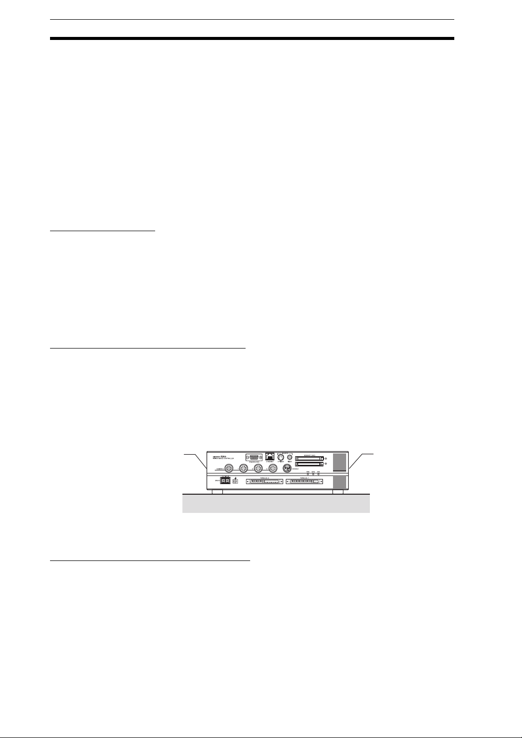
2-3 Component Names and Functions
The following diagram shows the F250 Controller’s major components.
1. RS-232C/RS-422 Conn ec tor
Connects the F250 to an external device such as a personal computer or
PLC.
2. Ethernet Connector (10BASE-T)
Connects the F250 to a personal co mputer. (Can be used with F250-UME
Application Software version 1.10 or higher.)
3. Monitor Connector (S-VIDEO Output)
Connects to a monitor with an S-VIDEO input.
4. Monitor Connector (Comp os ite Vide o Output)
Connects to a monitor.
5. Memory Card Slots 0 and 1
Memory Cards such as the Application Software Memory Card can be inserted in these slots.
6. Memory Card Indicators 0 and 1
Lit when power is bei ng supplie d to the corresp onding Mem ory Card. (The
Memory Card must not be inserted or removed when this indicator is lit.)
7. Console Connec tor
Connects the F250 to a Console.
8. ERROR Indicator
Lit when an error has occurred.
9. RUN Indicator
Lit while the F250 is in Run Mode.
10. POWER Indicator
Lit while power is ON.
11. Parallel Connectors 0 and 1
Connect the F250 to external devices such as a sync sensor or PLC.
12. Camera Connectors 0 to 3
Connect to the Cameras.
13. Ground Terminal
Connects to the ground wire.
14. Power Supply Terminals
Connect to the DC power supply.
14
Page 27

Mounting the Controller Section 2-4
2-4 Mounting the Controller
There are two ways to mount the Vision Mate Controller: horizontal mounting,
or vertical mounting. (All dimensions are in mm.)
F250 Dimensions
This screw hole
cannot be used.
270
115 min.
73
(25)
(40)
220
190
0.6
0.6
2-4-1 Horizontal Mounting
For proper air flow, provide at least 20 mm of clearance from the top of the
Controlle r and at leas t 50 mm of cleara nce from th e sides (next to the intake
and exhaust vents).
8
Four M4 taps
(for mounting)
0.5(14)
136
CHECK Use the correct screw length. If
197
Stopper
10 to 13
Panel
The screw length L must be
in the following range:
10+T < L < 13+T
the screw extends more than 13
mm past the panel, the stopper
may bend and contact the
Controller’s internal PC board.
This screw hole
cannot be used.
thickness: T
50 min.
(Intake)
20 min.
50 min.
(Exhaust)
115 min.
20 min.
8 mm
15
Page 28

Mounting the Controller Section 2-4
2-4-2 Vertical Mounting
For proper air flow, provide at least 20 mm of clearance from the top of the
Controller and at least 50 mm of clearance from the sides (next to the intake
and exhaust vents).
50 min.
(Exhaust)
20 min.
50 min.
(Intake)
115 min.
20 min.
View from bottom
Precaution The Controller must be installed with the air intake side down and the air
exhaust side up.
Correct
Exhaust
Incorrect
Intake
16
Intake
Exhaust
Page 29

Connecting Peripheral Devices Section 2-5
2-5 Connecting Peripheral De vices
This section shows how to connect peripheral devices to the F250.
Precaution Always turn OFF the power supply before connecting or disconnecting a
peripheral device’s cable. The peripheral device may be damaged if it is connected while the power is ON.
The various connectors on the F250 are capped when the F250 is shipped.
When a connector is not being used, leave the cap in place or replace the cap
to protect against dust, dirt, and static electricity.
2-5-1 Connecting a Console
Connect the Console to the F250’s CONSOLE connector. An F160-KP or
F150-KP Console can be connected. Install the provided ferrite core onto the
cable, positioning the ferrite core about 10 mm from the F250-side connector.
SHIFT
ENT
TRIGESC
Approx. 10 mm
Ferrite core
CONSOLE
2-5-2 Connecting a Monitor
Connect the monitor cable to the F250’s MONITOR connector. Install the provided ferrite core onto the F150-VM Monitor Cable, positioning the ferrite core
about 10 mm from the F250-si de con nector. The S-VIDEO and VIDEO outputs
can be used simultaneously.
Ferrite core
POWER
SYNC
VIDEO
S-VIDEO
Approx. 10 mm
2-5-3 Connecting a Camera
Connect the camera cable to the F250's CAMERA connector.
CAMERA
Overview of Available Cameras
The F250 Camera with L ight is a speci al Came ra th at ha s a sp ecial lens and
light source alread y attached. The light so urc e a nd len s are contained in a sin-
17
Page 30

Connecting Peripheral Devices Section 2-5
ON↑
12
gle unit, so installation is very simple. Just mount the Camera at the proper
distance from the measurement object and it is ready to use.
Camera with Light
Item F150-SL20A F150-SL50A
Field of vision 20 mm
Mounting distance 61 to 71 mm 66 to 76 mm
Relationship
between Camera
and object
20 mm 50 mm 50 mm
Measurement
Mounting distance
object
Field of vision
Lighting precautions None in particular
Camera with Intelligent Lighting
Item F150-SLC20 or F160-SLC20 F150-SLC50 or F160-SLC50
Field of vision 20 mm
Mounting distance 15 to 25 mm 16.5 to 26.5 mm
Relationship
between Camera
and object
Measurement
object
Lighting precautions Use with DIP switch pins 1 and 2 both set to
OFF.
20 mm 50 mm 50 mm
Mounting distance
Field of vision
Use with DIP switch pins 1 and 2 both set to
OFF.
O
1
F
F
2
Camera Only
Item F150-S1A or F160-S1
Field of vision and
distance to object
Determine the required field of vision based on the size of the measurement object and
select an appropriate CCTV lens (C mount).
Lighting precautions Provide a light source appropriate for the measurement object.
CHECK Observe the following precautions when using a Camera with Light or Camera
with Intelligent Lighting.
18
Page 31

Power Supply and Ground Section 2-6
• The lens has a fixed focal point. The actual field of vision and focal point
vary from lens to lens, so adjust the distance to the measurement object
after replacing the lens or camera.
• The camera mounting distance listed in the following tables is an approximate value. Mount the Camera so that the distance to the measurement
object can be adjusted easily.
If the object size and field of vision are incompatible, use a standard CCTV
lens and light source.
SeeAlso page 22
2-6 Power Supply and Ground
Wire the power supply and the ground to their respective terminals. Tighten
the screws to a torque of between 0.49 N¼m.
After wiring, confirm that the wiring is correct.
2-6-1 Crimp Terminals and Cables
The terminal block uses M3 terminal screws. Use appropriate crimp terminals
for M3 screws, as shown below.
Forked Round
6.2 mm max.
Applicable wire size: Ins ula ted w ire of 1. 31 t o 1.65 mm2 (AWG16 to AWG15)
2-6-2 Ground (Earth) Wiring
Always connect a ground wire to the F250's ground terminal. To avoid grounding problems, do not share the ground wire with any other devices or wire the
ground to the building's steel framing.
Use a grounding poin t that is as clo se as pos sib le a nd k eep th e gro und wire as
short as possible.
6.2 mm max.
Ground to 100 W or less
19
Page 32

Power Supply and Ground Section 2-6
2-6-3 Wiring the Power Supply
Wire the Power Supply Unit independently of other devices. In particular, keep
the power supply wired separately from inductive loads. Also, keep the power
supply wiring as short as possible (less than 10 m).
Use a power supply that meets the following specifications. We recommend
using OMRON’s S82K-10024 Power Supply.
Item Specification
Output current 3.7 A min.
Power supply voltage
24 VDC
+10%
/
-
15%
CHECK Use a DC power supply with countermeasures against high voltages (safe
extra low-voltage circuits on the secondary side). If the system must meet UL
standards, use a UL class II power supply.
−
+
24 VDC
!Caution Keep the power supply line as short as possible (less than 10 m).
After wiring, replace the protective cover on the power supply terminals.
20
Page 33

SECTION 3
Lenses, Lighting, and Memory Cards
This section provides additional information on CCTV lenses, lighting, and Memory Cards.
3-1 CCTV Lenses . . . . . . . . . . . . . . . . . . . . . . . . . . . . . . . . . . . . . . . . . . . . . . . . . 22
3-1-1 Optical Chart . . . . . . . . . . . . . . . . . . . . . . . . . . . . . . . . . . . . . . . . . . 22
3-1-2 Lenses and Lens Diameters . . . . . . . . . . . . . . . . . . . . . . . . . . . . . . . 23
3-1-3 Extension Tubes . . . . . . . . . . . . . . . . . . . . . . . . . . . . . . . . . . . . . . . . 24
3-2 Lighting. . . . . . . . . . . . . . . . . . . . . . . . . . . . . . . . . . . . . . . . . . . . . . . . . . . . . . 25
3-2-1 Lighting Methods. . . . . . . . . . . . . . . . . . . . . . . . . . . . . . . . . . . . . . . 25
3-3 Memory Cards . . . . . . . . . . . . . . . . . . . . . . . . . . . . . . . . . . . . . . . . . . . . . . . . 27
3-3-1 Installing a Memory Card. . . . . . . . . . . . . . . . . . . . . . . . . . . . . . . . . 27
3-3-2 Removing the Memory Card . . . . . . . . . . . . . . . . . . . . . . . . . . . . . . 27
3-3-3 Using Memory Cards in a Personal Computer. . . . . . . . . . . . . . . . . 28
21
Page 34

CCTV Lenses Section 3-1
3-1 CCTV Lenses
When using a Camera without a light (F150-S1A or F160-S1), refer to the following graph to select the appropriate Lens and Extension Tube. The lens will
differ depending on the size of the measurement object and the distance from
the Camera.
3-1-1 Optical Chart
The values in the following chart are approximations, a nd th e Cam era must be
adjusted after it is mounted.
Lens model: 3Z4S-LE
5,000
3,000
Camera distance A (mm)
2,000
1,000
500
300
200
100
50
4 5 10 20 30 50 100 200 300 500
t: Extension Tube length
Field of vision L (mm)
The X axis of the graph s ho w s field of vision L (mm), and the Y axi s shows the
camera distance A (mm). The curves on the graph show the relationship
between the field of vision and camera distance for each CCTV lens. The values are significantly different for each lens, so double-check the model of the
lens before using the graph. The “t” values indicate the lengths of the Extension Tubes. The value “t0” shows the case where an Extension Tube is not
needed and the value “t5.0” shows the case where a 5-mm Extension Tube is
used.
22
Page 35

CCTV Lenses Section 3-1
Example
When a 3Z4S-LE C1614A CCTV Lens is being used and a field of vision of
40 mm is needed at the measurement object, a camera distance of 200 mm
and 1-mm Extension Tube are required.
Camera
Extension Tube t@ (mm)
Lens
Camera distance A (mm)
Measurement object
Field of vision L (mm)
3-1-2 Lenses and Lens Diameters
Unit: mm
Max. outer dia.
Total length
Lens Focal length Bright-
ness
3Z4S-LE C418DX 4.8 mm F1.8 40.5 mm dia. 35.5 mm - -3Z4S-LE B618CX-2 6.5 mm F1.8 48 mm dia. 42 mm
3Z4S-LE C815B 8.5 mm F1.5 42 mm dia. 40 mm M40.5
3Z4S-LE B1214D-2 12.5 mm F1.4 42 mm dia. 50 mm
3Z4S-LE C1614A 16.0 mm F1.4 30 mm dia. 33 mm M27
3Z4S-LE B2514D 25.0 mm F1.4 30 mm dia. 37. 3 mm
3Z4S-LE B5014A 50.0 mm F1.4 48 mm dia. 48 mm M46
3Z4S-LE B7514C 75.0 mm F1.4 62 mm dia. 79 mm M58
1"-32UN
-2A
Maximum outer
diameter
30 dia.
Total length Filter size
P0.5
P0.75
P0.75
P0.5
23
Page 36

CCTV Lenses Section 3-1
3-1-3 Extension Tubes
One or more Extension Tubes can be inserted between the le ns and th e Cam era to focus the Camera image. Use a combination of one or more of the six
tubes to achieve the required length.
Extension Tube
Model Maximum outer
diameter
3Z4S-LE EX-C6 31 dia. Set of 6 tubes
0.5 mm, 1 mm, 5 mm, 10 mm, 20 mm, and
40 mm
Length: 40 mm 20 mm 10 mm 5 mm 1.0 mm 0.5 mm
Length
Precaution • Do not use the 0.5-mm and 1.0-mm Extension Tubes attached to each
other. Since these Extension Tubes are placed over the threaded section
of the Lens or other Extension Tube, the connection may loosen when
more than one 0.5-mm or 1.0-mm Extension Tube are used together.
• Reinforcement may be required for combinations of Extension Tubes
exceeding 30 mm if the Camera is subject to vibration.
24
Page 37

Lighting Section 3-2
3-2 Lighting
A stable image must be obtai ned t o ensure ac cu rate inspection. Use approp riate lighting for the application and the measurement object if using a Camera
without a light (F150-S1A or F160-S1).
3-2-1 Lighting Methods
Back Lighting
A stable, high-contrast image can be obtained using back lighting.
Applications: Inspection of exterior shape or positioning inspection
Camera
Reflected Lighting
Measurement object
Light source
Ring Lights
Light is shone uniformly on the measurement object.
Applications: Surface inspections
Camera
Light source
Measurement object
Oblique Lighting
Detection can be made util izing th e difference in regular an d diffus e reflect ed
light.
25
Page 38

Lighting Section 3-2
Applications: Inspections for surface gloss
Camera
Light source
Measurement object
Coaxial Lighting
A stable image can be obtained with few shadows from uneven surfaces on
the measurement object.
Applications: Surface inspections, positioning, and hole inspections of comparatively small objects
Half mirror
Camera
Light source
Measurement object
26
Page 39

Memory Cards Section 3-3
3-3 Memory Cards
Use a Memory Card to back up data such as settings and image data or
increase the number of sc en es when you are using the Scene G roup func tio n.
Data from the F250 can be backed up in the co mputer just by inse rting the
Memor y Card into the co mputer and c opying the desire d data. The following
procedures also apply to the Memory Card containing the F250-UME Application Software.
We recommend the OMRON F160-N64S (64 MB).
CHECK The F250 is equipped with two Memory Card slots. Use these slots for the fol-
lowing functions .
Function Slot number
F250-UME Application Software installation Slot 0 (Use slot 0 only.)
Memory Cards for scene groups Slot 1 (Use slot 1 only.)
Memory Cards for data backup Either slot 0 or 1 can be used.
Precaution A filler card with no memory is inserted into the F250’s Memory Card slot
before the F250 is shipped. Remove this filler card and install a Memory Card
to use the Memory Card functions.
If Memory Cards are not being used, leave the filler card in place to prevent
dust or dirt from entering the Memory Card slot.
3-3-1 Installing a Memory Card
1. Insert the Memory Card into the Memory Card slot.
CHECK The eject button will pop out slightly when the Memory Card is inserted
properly.
3-3-2 Removing the Memory Card
1. Turn OFF the power supply to the Memory Card or turn OFF the F250.
SeeAlso Refer to Section 4 Additional Func tion s in the F250 Vision Sensor Manual
2: Operation Manual for details on turning OFF the power supply to the
Memory Card.
2. Verify that the Memory Card indicator is not lit.
Memory card indicator
27
Page 40

Memory Cards Section 3-3
Precaution
Do not remov e the Me mo ry Card if the Mem ory Card indi ca tor i s l it. Do ing
so may damage the Memory Card or the F250 its elf.
3. Press the eject button to the right of the Memory Card slot. The Memory
Card will pop out slightly.
Precaution Do not remove the Memory Card without pressing the eject button. Doing so
may damage the F250.
Memory card eject button
4. Pull the Memory Card straight out from the slot.
3-3-3 Using Memory Cards in a Personal Computer
The F250’s Memory Cards can be used in a personal computer with a PC
Card drive (PCMCIA 2.0 or higher, type II compatible) or CompactFlash
drive.
The Memory Card must be inserted into a PC Card Adapter in order to be
used in a PC Card drive. We recommend the OMRON HMC-AP001 PC Card
Adapter.
™
PC Card
Adapter
28
Page 41

SECTION 4
Connecting External Devices
This section describes how to connect external devices through a parallel interface (a parallel connector) or serial
interface (the RS -232C/RS-422 connector or Ethernet connector).
4-1 Connecting through the Parallel Interface . . . . . . . . . . . . . . . . . . . . . . . . . . . 30
4-1-1 Parallel Connection Methods . . . . . . . . . . . . . . . . . . . . . . . . . . . . . . 30
4-1-2 Parallel Connector Specifications. . . . . . . . . . . . . . . . . . . . . . . . . . . 32
4-1-3 I/O Specifications. . . . . . . . . . . . . . . . . . . . . . . . . . . . . . . . . . . . . . . 36
4-2 Connecting through the Serial Interface. . . . . . . . . . . . . . . . . . . . . . . . . . . . . 37
4-2-1 RS-232C/RS-422 Connections. . . . . . . . . . . . . . . . . . . . . . . . . . . . . 37
4-2-2 Ethernet Connection. . . . . . . . . . . . . . . . . . . . . . . . . . . . . . . . . . . . . 40
29
Page 42

Connecting through the Parallel Interface Section 4-1
4-1 Connecting through the Parallel Interface
This section explains how to connect I/O to the F250 through its parallel interface to input signals such as measurement triggers or output signals such as
measurement results.
When you want to use the parallel interface to input commands and output
measurement results , pr epare a pa rall el I/O ca b le an d conn ect it to the par allel
connector. A Terminal Block can also be used to connect external devices.
Refer to the F250 Vision Sensor Manual 2: Operation Manual for details on
communications settings and I/O formats.
4-1-1 Parallel Connection Methods
Using a Parallel I/ O Cable
Use an F160-VP Parallel I/O Cable (sold separately) to connect the F250 to
external devices. Align the connectors and insert the cable’s connector
straight into the F250’s parallel connector. Tighten the connector’s mounting
screws to secure the connection.
Parallel
Connector 0
Parallel
Connector 1
Marks (1 to 4)
F160-VP Parallel
I/O Cable (2 m)
FG term inals
Ground to 100
W
or less.
Wire color
Precaution 1. Turn OFF the power supply before connecting or disconnecting a Parallel
I/O Cable. Peripheral devices may be damaged if the cable is connected
or disconnected ZLWKWKHSRZHU21
30
Page 43

Connecting through the Parallel Interface Section 4-1
2. The parallel connectors are capped with screw-on covers when the F250
is shipped. When a connector is not being used, leave the cover in place
or replace the cover to protect against dust, dirt, and static electricity.
Using a Screw T erminal Block
Use a Screw Terminal Block and Special Cable to connect the F250 to external devices such as PLCs.
Parallel
Connector 0
Parallel
Connector 1
Special Cable
XW2Z-100B (1 m)
XW2Z-200B (2 m)
XW2Z-300B (3 m)
XW2Z-500B (5 m)
XW2B-40G5 Screw
Terminal Block
PLC or other device
31
Page 44

Connecting through the Parallel Interface Section 4-1
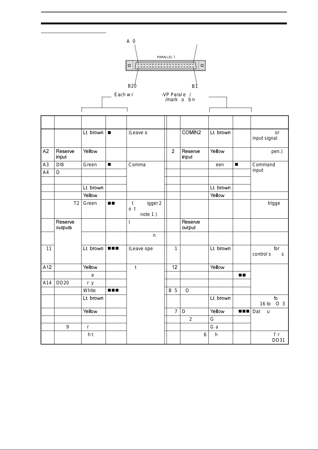
4-1-2 Parallel Connector Specifications
Parallel Connect or 0
A20
Each wire of the F160-VP Parallel I/O Cable
has a unique wire-color/mark combination.
A1
B1B20
Pin Signal Color Mark
(Black)
5(6(7 /WEURZQ
A1
$ 67(3 <HOORZ
A3 DI0 Green
A4 DI2 Gray
A5 DI4 White
A6 DI6
A7 (Open)
/WEURZQ
<HOORZ
A8 STGOUT0 Green
A9 RUN Gray
A10 BUSY White
A11 OR
$
DO0
/WEURZQ
<HOORZ
A13 DO2 Green
A14 DO4 Gray
A15 DO6 White
A16 DO8
A17 DO9
/WEURZQ
<HOORZ
A18 DO11 Green
A19 DO13 Gray
A20 DO15 White
■
■
■
■
■
■■
■■
■■
■■
■■
■■■
■■■
■■■
■■■
■■■
■■■■
■■■■
■■■■
■■■■
■■■■
Function Pin Signal Color Mark
5HVWDUWVWKH
B1
&20,1 /WEURZQ
)
0HDVXUHPHQW
B
'6$ <HOORZ
WULJJHUVLJQDO
LQSXW
Command
input
B3 DI1 Green
B4 DI3 Gray
B5 DI5 White
B6 DI7
(Leave open.) B7 (Open)
Strobe trigger 0
B8 STGOUT1 Green
/WEURZQ
<HOORZ
output (See
note 1.)
ON while in
B9 ERROR Gray
Run mode
ON during pro-
B10 GATE White
cessing
Combined
B11 COMOUT1
/WEURZQ
judgement
result
Data output BDO1
<HOORZ
B13 DO3 Green
B14 DO5 Gray
B15 DO7 White
B16 COMOUT2
B17 DO10
/WEURZQ
<HOORZ
B18 DO12 Green
B19 DO14 Gray
B20 COMOUT3 White
(Red)
■
■
■
■
■
■■
■■
■■
■■
■■
■■■
■■■
■■■
■■■
■■■
■■■■
■■■■
■■■■
■■■■
■■■■
Function
Common for
input signals
(See note 2.)
,QSXWVGDWD
VHQGUHTXHVW
VLJQDOV
Command
input
(Leave open.)
Strobe trigger 1
output (See
note 1.)
ON when there
is an error.
ON for the set
output time
Common for
control signals
(See note 3.)
Data output
Common for
DO0 to DO7
Data output
Common for
DO8 to DO15
Precaution Do not input the RESET input immediately after turning ON the power. When
using RESET input to synchronize startup timing, wait at lea st 1 s afte r turning
21WKH)VSRZHUVXSSO\EHIRUHWXUQLQJ21WKH5(6(7VLJQDO
CHECK Use a DC power supply with countermeasures against high voltages (safe
extra lo w-voltage circuits on the se conda ry side) f or the CO MIN and COM OUT
terminals. If the V\VWHPPXVWPHHW8/VWDQGDUGVXVHD8/FODVV,,SRZHUVXS
SO\
32
Page 45
Connecting through the Parallel Interface Section 4-1
Parallel Connector 1
A20
A1
Each wire of the F160-VP Parallel I/O Cable
has a unique wire-color/mark combination.
Pin Signal Color Mark
(Black)
A1 (Open)
$ 5HVHUYH
/WEURZQ
<HOORZ
■
■
LQSXW
A3 DI8 Green
A4 DI10 Gray
A5 DI12 White
A6 DI14
A7 (Open)
/WEURZQ
<HOORZ
A8 STGOUT2 Green
A9
5HVHUYH
Gray
■
■
■
■■
■■
■■
■■
RXWSXWV
A10 White
A11
$
DO16
/WEURZQ
<HOORZ
A13 DO18 Green
A14 DO20 Gray
A15 DO22 White
A16 DO24
A17 DO25
/WEURZQ
<HOORZ
A18 DO27 Green
A19 DO29 Gray
A20 DO31 White
■■
■■■
■■■
■■■
■■■
■■■
■■■■
■■■■
■■■■
■■■■
■■■■
B20
B1
Function Pin Signal Color Mark
(Leave open.) B1
(Leave open.) B
&20,1 /WEURZQ
5HVHUYH
<HOORZ
LQSXW
Command
input
B3 DI9 Green
B4 DI11 Gray
B5 DI13 White
B6 DI15
(Leave open.) B7 (Open)
Strobe trigger 2
B8 STGOUT3 Green
/WEURZQ
<HOORZ
output
(See note 1.)
(Leave open.) B9
5HVHUYH
Gray
RXWSXW
(Leave open.) B10 Reserve
White
output
(Leave open.) B11 COMOUT4
Data output BDO17
/WEURZQ
<HOORZ
B13 DO19 Green
B14 DO21 Gray
B15 DO23 White
B16 COMOUT5
B17 DO26
/WEURZQ
<HOORZ
B18 DO28 Green
B19 DO30 Gray
B20 COMOUT6 White
(Red)
■
■
■
■
■
■■
■■
■■
■■
■■
■■■
■■■
■■■
■■■
■■■
■■■■
■■■■
■■■■
■■■■
■■■■
Function
Common for
input signals
(See note 2.)
(Leave open.)
Command
input
(Leave open.)
Strobe trigger 3
output
(See note 1.)
(Leave open.)
(Leave open.)
Common for
control signals
(See note 3.)
Data output
Common for
DO16 to DO23
Data output
Common for
DO24 to DO31
Note 1. Refer to page 70 for details if you want to connect a strobe device to the
F250.
Each Camera has its own strobe trigger output as shown in the following
table.
33
Page 46

Connecting through the Parallel Interface Section 4-1
Camera Strobe trigger output signal
Camera 0 STGOUT0 (Pin A8 of parallel connector 0)
Camera 1 STGOUT1 (Pin B8 of parallel connector 0)
Camera 2 STGOUT2 (Pin A8 of parallel connector 1)
Camera 3 STGOUT3 (Pin B8 of parallel connector 1)
2. COMIN1 is the common for A1 to A6 and B2 to B6 on connector 0.
COMIN2 is the common for A3 to A6 and B3 to B6 on connector 1.
3. COMOUT1 is the common for A8 to A11 and B8 to B10 on connector 0.
COMOUT4 is the common for A8 and B8 on connector 1.
Wiring Connector-Terminal Block Conversion Units
Connector-Terminal Block Conversion Unit
Manufacturer Model
OMRON XW2B-40G5
Connecting Cables
Manufacturer Model
OMRON XW2Z-100B (1 m)
XW2Z-200B (2 m)
XW2Z-300B (3 m)
XW2Z-500B (5 m)
34
Page 47

Connecting through the Parallel Interface Section 4-1
Connecting to the F250 Connecting to Parallel Connector 0
Parallel
connector 0
1
Parallel
connector 1
39
Conversion
Unit Terminal
1 RESET 2 COMIN1
3STEP4DSA
5DI06DI1
7DI28DI3
9DI410DI5
11 DI6 12 DI7
13 Not used. 14 Not used.
15 STGOUT0 16 S T GOUT1
17 RUN 18 ERROR
19 BUSY 20 GATE
21 OR 22 COMOUT 1
23 DO0 24 DO1
25 DO2 26 DO3
27 DO4 28 DO5
29 DO6 30 DO7
31 DO8 32 COMOUT2
33 DO9 34 DO10
35 DO11 36 DO12
37 DO13 38 DO14
39 DO15 40 COMOUT3
Signal Conversion
Unit Terminal
Signal
Connector-Terminal Block
Conversion Unit
2
40
Connecting to Parallel Connector 1
Conversion
Unit Terminal
1 Not used. 2 COMIN2
3 Reserve
5DI86DI9
7DI108DI11
9 DI12 10 DI13
11 DI14 12 DI15
13 Not used. 14 Not used.
15 STGOUT2 16 S T GOUT3
17 Reserve
19 Reserve
21 Reserve
23 DO16 24 DO17
25 DO18 26 DO19
27 DO20 28 DO21
29 DO22 30 DO23
31 DO24 32 COMOUT5
33 DO25 34 DO26
35 DO27 36 DO28
37 DO29 38 DO30
39 DO31 40 COMOUT6
Signal Conversion
Unit Terminal
4 Reserve
input
18 Reserve
output
20 Reserve
output
22 COMOUT4
output
Signal
input
output
output
SeeAlso
Refer to the beginning of 3DUDOOHO &RQQHFWRU 6SHFLILFDWLRQV for signal
definitions.l
35
Page 48

Connecting through the Parallel Interface Section 4-1
Making a Parallel I/O Cable
A parallel I/O cable can be assem bled using the f o ll o w in g co nnector and cover
or equivalent components. Keep the cable length less than P
Component Manufacturer Model number
Connector Fujitsu
Cover Fujitsu
)&1-$8
)&1&%
CHECK Double-check the connector wiring for mistakes before turning ON the power
VXSSO\IRUWKHILUVWWLPH
4-1-3 I/O Specifications
Input Specifications
Item Specification
Model F250-C50 (NPN mode) F250-C55 (PNP mode)
Input voltage 12 to 24 VDC
ON current 5 to 15 mA
ON voltage 8.8 V max.
OFF current 0.1 mA max.
OFF voltage 4.5 V min.
ON delay RESET input: 10 ms max.
Other inputs: 0.5 ms max.
OFF delay RESET input:15 ms max.
Other inputs: 0.7 ms max.
Internal circuits
+
COM IN
Input
terminal
10%
Input
terminal
COM IN
Output Specifications
Item Specification
Model F250-C50 (NPN mode) F250-C55 (PNP mode)
Output voltage 12 to 24 VDC
Load current 45 mA max.
ON residual voltage 2 V max.
OFF leakage current 0.1 mA max.
Internal circuits
Precaution
Do not exceed the maximum lo ad current specified for the F250. Th e F2 50 w ill
10%
Output terminal
Load
COM OUT
+
be damaged if an output is short-circuited.
36
COM OUT
Load
Output terminal
Page 49

Connecting through the Serial Interface Section 4-2
4-2 Connecting through the Serial Interface
The F250’s serial interface (RS-232C/RS-422 connector or Ethernet connector) can be used to input signals such as measurement triggers or output signals such as measurement results. Additionally, data that has been set in the
F250 can be backed up in a personal computer.
Refer to Section 6 Communicating with External Devices in the F250 Vision
Sensor Manua l 2: Operation Manual for details on communications settings
and I/O formats.
4-2-1 RS-232C/RS-422 Connections
Connection Examples
1:1 Connection (Normal, Menu Operation)
RS-232C cable
F250
Multi-drop Connection (Normal)
Communications between one computer and several F250s is possible using
Link Adapters.
Link Adapter
OMRON
3G2A9-AL004-E
RS-422
cable
recommended
RS-422 cable
Link Adapter Link Adapter Link Adapter
RS-422 cable
F250
Computer
31 Units max.
RS-232C cable
Computer
OMRON
B500-AL001
recommended
F250 F250
CHECK When 3G2A9-AL004-E Link Adapters are being used, termination must be set
to ON in the last node in the line and the node must be terminated as follows:
• Connect 220 W (1/2 W min.) between RDA(
• Connect 220 W (1/2 W min.) between SDA(
-) and RDB(+).
-) and SDB(+).
37
Page 50

Connecting through the Serial In terface Section 4-2
1:1 Connection (Host Link)
RS-232C cable
Connector
F250
PLC
The F250’s RS-232C/RS-422 Connector is a 9-pin D-SUB female connector.
The pin allocation is shown below.
243
1
6
798
Pin Signal Name
1 FG Protective frame ground
2 SD For RS-232C
3RD
4 NC Not connected
5 RDB(+) For RS-422
6
7SDB(+)
8
9 GND Signal ground
5
RDA(
SDA(
-)
-)
The following plug and hood are recommended and are available from
OMRON.
Model Model No.
Plug XM2A-0901
Hood XM2S-0911
Wiring
RS-232C Wiring
38
The maximum cable length is 15 m for RS-232C or RS-422
Signal
SD
RD
GND
F250
Pin
2
3
9
Use only shielded cable.
External device
Pin
✽
✽
✽
Signal
SD
RD
GND
RS/CS control
cannot be used.
Page 51

Connecting through the Serial Interface Section 4-2
RS-422 Wiring
F250
Signal
RDB (+)
RDA (−)
SDB (+)
SDA (−)
GND
Pin
5
6
7
8
9
Use only shielded cable.
Note Pin numbers on the external device will depend on the device being con-
nected. Refer to the manual for the personal computer or PLC being connected.
External device
Pin
✽
✽
✽
✽
✽
Signal
RDB (+)
RDA (−)
SDB (+)
SDA (−)
GND
Connection
Align the connector with the socket and press the connector straight into
place. Tighten the two mounting screws to secure the connector.
Precaution Always turn OFF the power supply before connecting or disconnecting cables.
The peripheral device may be damaged if connected or disconnected with the
power supply turned ON.
Note The connector is capped when the F250 is shipped. When not using the serial
interface , lea v e the cap in pla ce to prot ect agai nst dus t, dirt, and static electricity.
39
Page 52

Connecting through the Serial In terface Section 4-2
4-2-2 Ethernet Connection
Connection Examples
■ 1:1 Connection
Use a Shielded (STP) 1 0 Base -T Cross ov e r Cab le to mak e t he 1:1 conne ction.
The cable length must be less than 30 m.
10 Base-T Crossover Cable (STP)
(Less than 30 m)
F250
Computer
■ 1:N Connection
A Hub can be used to communicate with two or more F 250s from a single
computer . Use Shield ed (STP) 10 Base-T S traig ht-throu gh Cab les to mak e the
1:N connections. The cable length between the F250s and the Hub must be
less than 30 m.
Computer
10 Base-T Straightthrough Cable (STP)
HUB
10 Base-T
Straight-through
Cable (STP)
(Less than 30 m)
10 Base-T
Straight-through
Cable (STP)
(Less than 30 m)
10 Base-T
Straight-through
Cable (STP)
(Less than 30 m)
40
F250
F250
F250
Page 53

Connecting through the Serial Interface Section 4-2
Connection
Align the connecto r wit h the soc k et a nd pre ss th e con nector stra ight i nto pl ace .
Precaution 1. Always turn OFF the po w er supp ly before connecting or d iscon necti ng ca-
bles. The periphe ral de vice ma y be da maged if conn ected or disco nnected
with the power supply turned ON.
2. The Ethernet connector is capped when the F250 is shipped. When the
Ethernet interface isn’t being used, leave the cap in place or replace the
cap to protect against dust, dirt, and static electricity.
CHECK Refer to Section 6 Communicating with External Devices in the F250 Vision
Sensor Manual 2: Operation Manual for details on setting the F250’s IP
Address and Subnet Mask.
41
Page 54

Page 55

SECTION 5
Troubleshooting and Maintenance
This section provides tables to help identify and correct hardware errors that may occur with the F250 as well as
information on maintenance and periodic inspections.
5-1 Troubleshooting . . . . . . . . . . . . . . . . . . . . . . . . . . . . . . . . . . . . . . . . . . . . . . . 44
5-1-1 Connection Errors. . . . . . . . . . . . . . . . . . . . . . . . . . . . . . . . . . . . . . . 44
5-1-2 Menu Operation Errors. . . . . . . . . . . . . . . . . . . . . . . . . . . . . . . . . . . 44
5-1-3 Parallel Interface Errors . . . . . . . . . . . . . . . . . . . . . . . . . . . . . . . . . . 44
5-1-4 Serial Interface (RS-232C/RS-422) Errors. . . . . . . . . . . . . . . . . . . . 45
5-1-5 Cameras . . . . . . . . . . . . . . . . . . . . . . . . . . . . . . . . . . . . . . . . . . . . . . 45
5-1-6 Memory Cards . . . . . . . . . . . . . . . . . . . . . . . . . . . . . . . . . . . . . . . . . 45
5-1-7 Serial Interface (Ethernet) Errors. . . . . . . . . . . . . . . . . . . . . . . . . . . 46
5-1-8 Cabling Errors . . . . . . . . . . . . . . . . . . . . . . . . . . . . . . . . . . . . . . . . . 46
5-2 Maintenance . . . . . . . . . . . . . . . . . . . . . . . . . . . . . . . . . . . . . . . . . . . . . . . . . . 46
5-2-1 Replacing the Light . . . . . . . . . . . . . . . . . . . . . . . . . . . . . . . . . . . . . 46
5-3 Regular Inspections. . . . . . . . . . . . . . . . . . . . . . . . . . . . . . . . . . . . . . . . . . . . . 49
5-4 Specifications . . . . . . . . . . . . . . . . . . . . . . . . . . . . . . . . . . . . . . . . . . . . . . . . . 50
5-5 F200/F300 Camera Parameters. . . . . . . . . . . . . . . . . . . . . . . . . . . . . . . . . . . . 68
5-6 Connecting a Strobe Device . . . . . . . . . . . . . . . . . . . . . . . . . . . . . . . . . . . . . . 70
43
Page 56

Troubleshooting Section 5-1
5-1 Troubleshooting
This section lists probable co rrec tio ns for common h ardw a re problems. Plea se
check all of the following items before requesting repairs.
5-1-1 Connection Errors
Problem Probable cause
The POWER indicator is not lit. The Power Supply is not connected properly.
+10%
/
The supply voltage is not 24 VDC
The Video Monitor is blank. The power to the Video Monitor is not ON.
The Monitor Cable is not connected properly.
The Video Monitor is malfunctioning.
When using an LCD Monitor, the power supply capacity is insufficient.
The Video Monitor image is not
clear.
Cannot make key inputs from the
Console.
Camera images do not appear on
the screen (for Cameras with Light
Source).
Camera images do not appear on
the screen (when a standard CCTV
lens and lighting are used).
The indicators do not turn ON (for
Cameras with Light Source).
There is electrical noise entering from the power supply or cables.
The Monitor Cable is not correctly connected.
The Console Cable is not correctly connected.
The Camera Cable is not correctly connected.
The lighting cable is not properly connected to the Camera.
The lens cap has not been removed.
The Camera Cable is not properly connected.
The lens iris is opened or closed too far.
The shutter speed is not suitable.
The lighting method is not suitable.
The lighting cable is not correctly connected to the Camera.
Power is not being supplied to the F250.
When using a Camera with Intelligent Lighting, the DIP switch pins are not
set to 0.
-15%
.
5-1-2 Menu Operation Errors
Problem Probable cause
The measurement results are not
displayed on the Video Monitor.
The F250 is not in Monitor or Run mode.
5-1-3 Parallel Interface Errors
Problem Probable cause
Trigger signals (input signals) are
not received.
Signals cannot be output externally. The trigger signal has not been input.
44
The cables are not correctly wired.
The signal line is disconnected.
The status of communications can be checked with the I/O monitor.
The F250 is not in Monitor or Run mode.
The cables are not correctly wired.
The signal line is disconnected.
The status of communications can be checked with the I/O monitor.
The F250 is not in Run mode.
Page 57

Troubleshooting Section 5-1
5-1-4 Serial Interface (RS-232C/RS-422) Errors
Problem Probable cause
No communications are possible. The cables are not correctly wired.
The F250’s communications specifications do not match those of the
external device.
The communications mode was not selected under System settings/
Communication/Serial.
Select Normal, Host link, or Menu in the Communications (Serial)
menu. (Normal is no-protocol.)
The status of communications can be checked with the I/O monitor.
The Unit operates well initially, but
after a while there is no response
from the F250.
Cannot perform menu operations
from the computer.
Data cannot be saved • Are the same communications conditions set for both the external
The reception buffer on the external device (e.g., computer) is full. Check
that settings allow the data to be properly received.
The communications mode was not set to Menu in the System settings/
Communication/Serial settings.
device and the F250?
• Is flow control turned OFF under S ystem settings/communication/
Normal? Refer to the F250 Operation Manual.
5-1-5 Cameras
Problem Probable cause
Are the shutter trigger pulses synchronized when more than one
camera is connected?
The shutter trigger pulses are not synchronized for the F160-S1 and
F150-S1. The timing is offset so that light from other Cameras does not
enter. The offset depends on the model of Camera that is used.
Can more than one internally synchronized Cameras be connected?
Can the F150-LT10A Light be connected to the F160-S1 Camera?
5-1-6 Memory Cards
Problem Probable cause
Can either of the Memory Card
slots be used?
Model F160-S1 F150-S1
tD Approx. 500
If a strobe is used, the strobe trigger
signals are also offset in the same way as
the shutter trigger pulses.
The shutter trigger pulses are synchronized for other Cameras, i.e., there
is no offset.
No. Only one F200-S Camera (internal sync) can be connected, and it
must be connected to Camera connector 0.
Yes, it can be connected and the following Lenses are available.
• Lens with 20-mm field of vision: F150-LE20
• Lens with 50-mm field of vision: F150-LE50
Only the following two functions have restrictions in the slot that can be
used.
• Starting the Setup Menu: Slot 0 only
• Switching scene groups: Slot 1 only
Either slot can be used for all other functions (outputting results to a Memory Card, saving scene data, etc.).
m
s Approx. 1 ms
Camera 0
Camera 1
Camera 2
Camera 3
tD
Shutter trigger pulses ON
45
Page 58

Maintenance Section 5-2
5-1-7 Serial Interface (Ethernet) Errors
Problem Probable cause
No communications are possible. A 10 Base-T Crossover Cable is not being used for a 1:1 connection.
10 Base-T Straight-through Cables are not being used for the 1:N connections.
Power is not being supplied to the HUB, the settings are incorrect, or the
connections are incorrect.
The personal computer’s IP Address and Subnet Mask settings are not
correct or the settings are duplicated in another device.
The F250’s IP Address and Subnet Mask settings are not correct or the
settings are duplicated in another device.
The IP Address set for the F250 in the computer’s communications software is incorrect.
The communications mode was set to Normal or Menu in the System
settings/Communication/Serial window.
The status of communications can be checked with the I/O monitor.
The F250 is being accessed by another computer.
Communications are being affected by a noise source (such as a power
line) that is too close to the F250 or communications cables.
Communications are not set for a TELNET connection (TCP/IP , port 23) in
the computer’s communications software.
The Unit operates well initially, but
after a while there is no response
from the F250.
The response from the F250 is
slow.
(It takes too long to transfer data
and errors occur.)
Cannot perform menu operations
from the computer.
The reception buffer on the external device (e.g., computer) is full. Check
that settings allow the data to be properly received.
The IP Address of the F250 or computer is duplicated in another device.
Communications are being affected by a noise source (such as a power
line) that is too close to the F250 or communications cables.
The network’s communications load is too heavy.
The computer’s processing load is too heavy. (A program that requires a
lot of processing capacity is being run simultaneously.)
The communications mode was not set to Menu in the System settings/
Communication/Serial settings.
5-1-8 Cabling Errors
Problem Probable cause
A recommended OMRON RS-232C
cable is not being used.
Can a commercially available cable
be used instead of the R150-VM
Monitor Cable?
One of the following OMRON cables can be used. Select a cable that
works with the device being connected.
Connecting to a PC/AT or compatible computer (9-pin connector)
• XW2Z-200S-V (2 m)
• XW2Z-500S-V (5 m)
Connecting to a SYSMAC device (9-pin connector)
• XW2Z-200T (2 m)
• XW2Z-500T (5 m)
Yes, as long as it’s a pin jack cable (with a yellow connector) for video
signal connection.
5-2 Maintenance
5-2-1 Replacing the Light
• The Light will gradua lly lose bright ness over time (about 20% loss after
1,500 hours of use). Replace the Light after about 1,500 hours of use.
46
Page 59

Maintenance Section 5-2
• Replace the Light if it is damaged or not fully functional.
F150-SL20A/SL50A
Use the following procedure to replace a Light with the F150-LT10A Light.
(The F150-LT10A cannot be connected to the older F150-S1 Camera.)
Removing the Light
Camera base
2
3
Hold this part when
removing the Cable.
1
4
Light
Lighting connector
1. Disconnect the light cable from the light connec tor on the back of the Camera.
2. Remove the light cable from the slot in the camera base.
3. Remove the two screws securing the Light.
4. Remove the Light from the Camera.
Camera cable
connector
Precaution Do not disassemble the Lens. Disassembly can damage the Lens.
Installing the Light
Camera base
3
2
4
1
Light
Lighting connector
1. Mount the Light on the Camera.
2. Screw in the two screws that secure the Light.
3. Place the light cable in the slot in the camera base.
4. Connect the light cable to the light connector on the back of the Camera.
Camera cable
connector
47
Page 60

Maintenance Section 5-2
F150-SLC20/SLC50 or F160-SLC20/SLC50
Use the following procedure to replace a Light with an F150-LTC20 (20-mm
field of vision) or F150-LTC50 (50-mm field of vision) Light.
Removing the Light
5
3
Camera base
2
Light
4
1
Hold this part when
removing the Cable.
1. Disconnect t he li ght cab le from the lig ht conne ctor on the bac k of the C amera.
2. Remove the light cable from the slot in the camera base.
3. Remove the two screws securing the Light at the top.
4. Remov e the two screws securing the Light at the bottom.
5. Remove the Light from the Camera.
Precaution Do not disassemble the Lens. Disassembly can damage the Lens.
CHECK When you w ant to use the Camera alone without connec tin g a n In telligent
Installing the Light
Lighting, use M2 3 screws in the bottom of the Camera instead of the
long screws removed in step 4. The screws removed in step 3 are not
needed.
1
Light
Camera base
4
3
2
5
1. Mount the Light on the Camera.
2. Screw in the two screws that secure the Light at the bottom.
3. Screw in the two screws that secure the Light at the top.
48
Page 61

Regular Inspectio ns Section 5-3
4. Place the light cable in the slot in the camera base.
5. Connect the light cable to the light connector on the back of the Camera.
5-3 Regular Inspections
To maintain the F250 in the bes t condition, perform the following regularly.
• Clean the Lens and LED indicators with a lens-cleaning wipe or blow off
dust with an aerosol air sprayer.
• Lightly wipe off dirt with a soft cloth.
Inspection point Details Tools required
Power supply The voltage measured at the power supply
terminals must be 24 VDC
Ambient temperature
Ambient humidity The operating ambient humidity inside the
Installation Each component must be firmly secured.
Indicators All indicators must light when the power is
The operating ambient temperature inside
the cabinet must be between 0 and 50
cabinet must be between 35% and 85%.
Each cable connector must be correctly
inserted and locked.
The Cameras must be firmly secured.
The camera lens mounts must be firmly
secured.
turned ON.
Verify that a through-image is displayed.
When using an Intelligent Lighting, verify
that the light level settings are set to their
maximum values.
+10%
/
-15%
.
Circuit tester
Thermometer
C.
Hygrometer
Phillips screwdriver
---
Precaution • Turn OFF the power and take safety precautions before conducting
inspections. Elec trical s hock can result from a ttempti ng s afety inspections
with the power turned ON.
• Do not use thinners or benzene to clean the F250. They will damage
F250 components.
49
Page 62

Specifications Section 5-4
5-4 Specifications
This section provides the specifications and dimensions of the F250 and its
peripheral devices. (All dimensions are in mm unless otherwise noted.)
F250-C50/C55 Vision Mate Controller
270
115 min.
73
8
(25)
(40)
Item Specification
Model F250-C50 F250-C55
Input/Output type NPN PNP
Supply voltage 20.4 to 26.4 VDC
Current consumption 3.0 A max.
Insulation resistance 20 M
Dielectric strength 1,000 VAC, 50/60 Hz between all DC external terminals and GR terminal (with internal
Leakage current 10 mA max.
Noise resistance 2,000 V; pulse width: 50 ns; rise time: 5 ns (pulse)
Vibration resistance
Shock resistance
Ambient temperature Operating: 0 to 50
Ambient humidity Operating and storage: 35% to 85% (with no condensation)
Ambient environment No corrosive gases
Ground Class 1 (Ground resistance 100
Degree of protection IEC60529 IP20 (in-panel)
Case material SECC-T
220
0.6
190
0.6
W
min. between all DC external terminals and GR terminal (100 VDC Megger, with
internal surge absorber removed)
surge absorber removed)
Burst continuation time: 15 ms; Period: 300 ms
10 to 150 Hz; half-amplitude: 0.1 mm; maximum acceleration: 15 m/s
minutes each in 3 directions.
2
150 m/s
Storage:
, 3 times each in 6 directions
-25 to 65
Four M4 taps
(for mounting)
0.5(14)
136
C (with no condensation)
C (with no condensation)
W
max.)
This screw hole
cannot be used.
Screw length L:
10+T < L < 13+T
197
Stopper
10 to 13
Panel thickness:
T
2
, 10 times for 8
50
Page 63

Specifications Section 5-4
Item Specification
Battery life Approximately 7 years when used 24 hours/day.
Weight Approx. 3.1 kg (Controller only)
F150 Cameras
Cameras with Light
■ F150-SL20A/SL50A
(70.5)
3.8 dia.
Unit: mm
25.4
39
67
27
431
F150-LT10A Light
(50.25)
(40.25)
(16.75)
20±0.1
Two M4 taps, Depth 8
1/4-20UNC tap, Depth 8
(6.75)
51
Page 64

Specifications Section 5-4
Cameras with Intelligent Lighting
■ F150-SLC20
2.5
70
12
70
12
42.5
F150-LTC20 Light
73
40
(85)
(10)
4 dia.
Unit: mm
25
2.5
12
31
40
12
(96.25)
(86.25)
30.5
(16.75)
20±0.3
Two M4 taps, Depth 10
1/4-20UNC tap,Depth 10
(6.75)
52
Page 65

Specifications Section 5-4
■
F150-SLC50
90
16
90
16
2.52.5
52.5
F150-LTC50 Light
80
40
Unit: mm
(85)
(10)
4 dia.
25
31
1616
60
(103.25)
(93.25)
30.5
(16.75)
20±0.3
Two M4 taps, Depth 10
1/4-20UNC tap, Depth 10
(6.75)
53
Page 66

Specifications Section 5-4
Camera Only
■ F150-S1A
(6.2)
Light Connector
(8.8 dia.)
Unit: mm
(14.5)
(15.5)
48
8
(40)
(6)
(6.2)
29
1"-32UN-2A
(C mount)
31.25±2
21.25±2
30.5
(16.75)
20±0.1
(21.7)
11
1.5
Two M4 taps, Depth 8
1/4-20UNC tap, Depth 8
(6.75)
31
(30.7)
Camera Cable
Connector
(11.8 dia.)
54
Page 67

Specifications Section 5-4
F160 Cameras
Cameras with Intelligent Lighting
■ F160-SLC20
2.52.5
70
12
12
F150-LTC20 Light
73
46.5
Unit: mm
(85)
(10)
70
4 dia.
42.5
12
31
40
12
(96.25)
(86.25)
20±0.3
30.5
8
(23.25)
1/4-20UNC tap, Depth 10
Two M4 taps, Depth 10
(13.25)
25
55
Page 68

Specifications Section 5-4
F160-SLC50
■
90
16
16
F150-LTC50 Light
80
46.5
Unit: mm
(85)
90
Camera Only
(15.5)
(14.5)
31
60
■ F160-S1
(10)
4 dia.
52.5
2.5 2.5
1616
(103.25)
(93.25)
30.5
(23.25)
20±0.3
8
1/4-20UNC tap, Depth 10
Two M4 taps, Depth 10
(13.25)
54.5
8
(46.5)
(6)
(6.2)
(6.2)
25
Unit: mm
Light Connector
(8.8 dia.)
29
56
1"-32UN-2A
(C mount)
31.25±2
21.25±2
30.5 8
(23.25)
20±0.1
(13.25)
(21.7)
11
31
Two M4 taps, Depth 8
1/4-20UNC tap, Depth 8
(30.7)
Camera Cable
Connector
(11.8 dia.)
Page 69

Specifications Section 5-4
Camera Specifications
General Specifications
Item Specification
Supply voltage F150-series: 12 VDC
Current consumption F150-S1A: 100 mA max.
Vibration resistance
Shock resistance
Ambient temperature Operating: 0 to 50
Ambient humidity Operating and storage: 35% to 85% (with no condensation)
Ambient environment No corrosive gases
Camera materials Cover: Galvanized steel sheet metal
Light materials
(Cameras with Lights)
Weight F150-S1A: Approx. 80 g
F160-series: 13 VDC
F150-SL20A/SL50A: 110 mA max.
F150-SLC20/SLC50: 200 mA max.
F160-S1: 130 mA max.
F160-SLC20: 260 mA max.
F160-SLC50: 310 mA max.
10 to 150 Hz; half-amplitude: 0.35 mm; maximum acceleration: 50 m/s
minutes each in 3 directions
2
150 m/s
Storage:
Case: Die-cast aluminum alloy
Camera mounting base: Fiber-reinforced plastic (black)
Case: ABS
Transparent cover: PC
F150-SL20A/SL50A: Approx. 135 g
F150-SLC20: Approx. 280 g
F150-SLC50: Approx. 370 g
F160-S1: Approx. 85 g
F160-SLC20: Approx. 285 g
F160-SLC50: Approx. 375 g
, 3 times each in 6 directions
-25 to 65
C (with no condensation)
C (with no condensation)
2
, 10 times for 8
Characteristics
■ Camera Characteristics
Item Specification
Picture element 1/3" Interline CCD (reading all pixels)
Effective pixels 659
Synchronization External sync. via horizontal sync signal
Shutter speed
(Electronic shutter)
Lens mounting C mount
494 (H V)
F150-series: 1/100 s, 1/500 s, 1/2000 s, 1/10000 s
F160-series: 1/120 s, 1/200 s, 1/500 s, 1/1000 s, 1/2000 s, 1/4000 s, 1/8000 s,
1/20000 s
■ Lens Characteristics (Cameras with Lights only)
Item Specification
Lens model F150-SL20A: F150-LE20
Method Fixed focal point, fixed iris
F150-SL50A:F150-LE50
F150-SLC20:F150-LE20
F150-SLC50:F150-LE50
F160-SLC20:F150-LE20
F160-SLC50:F150-LE50
57
Page 70

Specifications Section 5-4
Item Specification
Brightness F2.8
Focal point distance F150-SL20A: 13 mm
Item Specification
Light model F150-SL20A /SL50A: F150-LT10A
Light source F150-SL20A/SL50A:
Light emission method Pulse emission (synchronized with the camera shutter)
F150-SL50A: 6.1 mm
F150-SLC20:13 mm
F150-SLC50: 6.1 mm
F160-SLC20:13 mm
F160-SLC50: 6.1 mm
■
Light Characteristics (Cameras with Lights only)
F150-SLC20:F150-LTC20
F150-SLC50:F150-LTC50
F160-SLC20:F150-LTC20
F160-SLC50:F150-LTC50
Red LED (Peak emission wavelength: 680 nm)
F150-SLC20/SLC50 and F160-SLC20/SLC50:
Red and green LED combination
(Peak emission wavelengt hs: 660 nm and 570 nm)
■ Other Characteristics
Item Specification
Mounting distance F150-S1A: Depends on lens being used.
Field of vision F150-S1A: Depends on lens being used.
F150-SL20A: 61 to 71 mm
F150-SL50A: 66 to 76 mm
F150-SLC20: 15 to 25 mm
F150-SLC50: 16.5 to 26.5 mm
F160-S1: Depends on lens being used.
F160-SLC20: 15 to 25 mm
F160-SLC50: 16.5 to 26.5 mm
F150-SL20A: 20 mm
F150-SL50A: 50 mm
F150-SLC20: 20 mm
F150-SLC50: 50 mm
F160-S1: Depends on lens being used.
F160-SLC20: 20 mm
F160-SLC50: 50 mm
20 mm
50 mm
20 mm
50 mm
20 mm
50 mm
58
Page 71

Specifications Section 5-4
Consoles
■ F150-KP Console
Unit: mm
50
ESC TRIG
ENT
131.5
87
SHIFT
CONSOLE
232000
510
12 dia.
40
34
4.8 dia.
Item Specification
Vibration resistance 10 to 150 Hz; half-amplitude: 0.15 mm; 4 times for 8 minutes each in 3 directions
Shock resistance
Ambient temperature Operating: 0 to 50
196 m/s
Storage:
2
; 3 times each in 6 directions
-25 to 65
C (with no condensation)
C (with no condensation)
Ambient humidity 35% to 85% (with no condensation)
Ambient environment No corrosive gases
Degree of protection IEC60529 IP20 (in-panel)
Minimum bending
75 mm
radius
Materials Body: ABS
Cable sheathing: Heat-resistant chlorinated vinyl
Connector: PC and PBT
Weight Approx. 135 g
12.5
59
Page 72

Specifications Section 5-4
F160-KP Console
■
29.7
Unit: mm
20
135.5
ESC
F1 F3
F4 F6
F7 F9
4.8 dia.
48
SHIFT
ENT
TRIG
F2
F5
F8
2000
34
40
12 dia.
Item Specification
Current consumption Approx. 10 mA
Vibration resistance
10 to 150 Hz; half-amplitude: 0.35 mm; maximum acceleration: 50 m/s
minutes each in 3 directions
Shock resistance
Ambient temperature Operating: 0 to 50
150 m/s
Storage:
2
; 3 times each in 6 directions
-25 to 65
C (with no condensation)
C (with no condensation)
Ambient humidity 35% to 85% (with no condensation)
Ambient environment No corrosive gases
Degree of protection IEC60529 IP20 (in-panel)
Minimum bending
75 mm
radius
Materials Body: ABS
Cable sheathing: Heat-resistant chlorinated vinyl
Connector: PC and PBT
Weight Approx. 160 g
2
,10 times for 8
60
Page 73

Specifications Section 5-4
CHECK
The switch on the back of the F160-KP must be set to “ENABLE”.
SHIFT
ENT
ESC TRIG
F1F2F3
F4F5F6
These keys will be disabled if
F7F8F9
ENABLE
DISABLEEENABLE
the switch is set to "DISABLE".
Cables
Camera Cables
■ Camera Cable Specifications
The F150-VS, F160-VSR3, and F160-VSR4 Camera Cables have different
dimensions and wiring, but they share the same specifications.
Item Specification
Vibration resistance 10 to 150 Hz; half-amplitude: 0.15 mm, 4 times for 8 minutes each in 3 directions
Shock resistance
Ambient temperature Operating: 0 to 50
Ambient humidity 35% to 85% (with no condensation)
Ambient environment No corrosive gases
Materials Cable sheathing: Heat-resistant chlorinated vinyl
Minimum bending
radius
Weight Approx. 170 g
2
196 m/s
Storage:
, 3 times each in 6 directions
-25 to 65
C (with no condensation)
C (with no condensation)
Connector: Fiberglass-reinforced PC and PBT
75 mm
61
Page 74

Specifications Section 5-4
F150-VS Camera Cable (For F150-S@, F160-S@ Cameras)
■
3000
Unit: mm
15 dia.
36
51
(30)
20 dia.
F250 Connector
Signal
Power
GND
GND
VIDEO GND
VD
ESCNT1
VIDEO
HD
SCAN
ESCNT2
INDEX
TRG
Shell
Connector model:
Hirose RP17A-13PA-12PC
Pin
1
2
3
4
5
6
7
8
9
10
11
12
6 dia.
Camera Connector
Pin
1
2
3
4
5
6
7
8
9
10
11
12
Connector model:
Hirose HR10A-10P-12S
Signal
GND
Power
GND
VIDEO
VIDEO GND
HD
Not used.
ESCNT1
ESCNT2
INDEX
TRG
SCAN
Shell
43
14.7 dia.
62
Page 75

Specifications Section 5-4
■
F160-VSR3 Camera Cable (For F300-S2R/S3DR/S4R and F200-S@
Cameras)
15 dia.
46
(120)
F250 Connector
Signal
Power
GND
GND
VIDEO GND
VD
ESCNT1
VIDEO
HD
SCAN
ESCNT2
INDEX
TRG
Shell
Connector model:
Hirose RP17A-13P-12PC
Pin
1
2
3
4
5
6
7
8
9
10
11
12
3000
5.3 dia.
Camera Connector
Pin
1
2
3
4
5
6
7
8
9
10
11
12
Connector model:
Hirose HR10A-10P-12S
Signal
GND
Power
VIDEO GND
VIDEO
HD GND
HD
VD
GND
−
INDEX(SI)
TRG
VD GND
Shell
Unit: mm
43
14.7 dia.
63
Page 76

Specifications Section 5-4
F160-VSR4 Camera Cable (For F300-S Cameras)
■
15 dia.
(120)
46
F250 Connector
Signal
Power
GND
GND
VIDEO GND
VD
ESCNT1
VIDEO
HD
SCAN
ESCNT2
INDEX
TRG
Pin
1
2
3
4
5
6
7
8
9
10
11
12
Shell
Connector model:
Hirose RP17A-13P-12PC
3000
17.4 dia.
5.3 dia.
Camera Connector
Pin
1
2
3
4
5
6
7
8
9
10
11
12
Signal
GND
Power
VIDEO GND
VIDEO
HD GND
HD
VD
GND
−
INDEX(SI)
Power
VD GND
Shell
Connector model:
Hirose HR10A-10P-12S
Unit: mm
43
14.7 dia.
F150-VM Monitor Cable
2000
46.7
11.5 dia.
3.3 dia.
Item Specification
Vibration resistance 10 to 150 Hz; half-amplitude: 0.15 mm, 4 times for 8 minutes each in 3 directions
Shock resistance
Ambient temperature Operating: 0 to 50
196 m/s
Storage:
2
, 3 times each in 6 directions
-
25 to 65 C (with no condensation)
C (with no condensation)
Ambient humidity 35% to 85% (with no condensation)
Ambient environment No corrosive gases
Materials Cable sheathing: Heat-resistant chlorinated vinyl
Connector: PVC
Unit: mm
46.7
64
Page 77

Specifications Section 5-4
Item Specification
Minimum bending
radius
Weight Approx. 40 g
Accessories BNC Jack Adapter
F160-VP Parallel I/O Cable
50 mm
Unit: mm
40
40
20
200
2000
40
20
11.6 dia.
200
200
Item Specification
Vibration resistance 10 to 150 Hz; half-amplitude: 0.15 mm, 4 times for 8 minutes each in 3 directions
Shock resistance
Ambient temperature Operating: 0 to 50
196 m/s
Storage:
2
, 3 times each in 6 directions
-
25 to 65 C (with no condensation)
C (with no condensation)
Ambient humidity 35% to 85% (with no condensation)
Ambient environment No corrosive gases
Materials Cable sheathing: Heat-resistant PVC
Connector: Polyester resin
Minimum bending
120 mm
radius
Weight Approx. 340 g
50
65
Page 78

Specifications Section 5-4
F150-M05L LCD Color Monitor
Unit: mm
Mounting plate thickness: 1.6 to 4.8
(46 max.)
Mounting bracket
POWER
(155)
143
SYNC
132
(145)
(100)
185
174
Panel opening dimensions
+0.5 mm
175.5
0
Item Specification
Supply voltage 20.4 to 26.4 VDC
Current consumption 700 mA max.
Vibration resistance
10 to 150 Hz; half-amplitude: 0.1 mm; maximum acceleration: 15 m/s
minutes each in 3 directions
Shock resistance
Ambient temperature Operating: 0 to 50
150 m/s
Storage:
2
, 3 times each in 6 directions
-25 to 65
C (with no condensation)
C (with no condensation)
Ambient humidity 35% to 85% (with no condensation)
Ambient environment No corrosive gases
Degree of protection IEC60529 IP20 (in-panel)
Materials Case: ABS/PC
Display surface: PMMA (Acrylic)
Panel size 5.5 inches (111.36
83.52 mm (H V))
Panel type TFT color liquid crystal
Resolution 320
Image pitch 0.348
240 dots
0.348 mm (H V)
Contrast 85:1 (typical)
Viewable angle 25
Luminance
up/down and 50 left/right (with a contrast ratio > 10)
250 cd/m
2
(typical)
Backlight Cold cathode fluorescent light
Response speed 60 ms max.
Input signal NTSC composite video (1.0 V/75
W
(5.5)
42.2
133.5
termination)
50 min.
F150-VM Monitor Cable
• Tolerance: ±1 mm
The dimensions in parentheses
are provided for reference.
+0.5 mm
0
2
, 10 times for 8
66
Page 79

Specifications Section 5-4
Item Specification
Weight Approx. 1 kg
Accessories Four mounting brackets
F150-M09 Video Monitor
Unit: mm
222
2335
143
250
190
Item Specification
Supply voltage 85 to 264 VAC, 50/60 Hz
Current consumption 20 W max.
Vibration resistance
Ambient temperature
Ambient humidity 10% to 90% (with no condensation)
Ambient environment No corrosive gases
Materials Front: ABS plastic
CRT size 9 inch (164
CRT type Monochrome CRT
Resolution 800 TV lines min. (at center)
System Number of scanning lines: 600
I/O impedance 75
I/O level and polarity Composite image signal: 1 V (peak to peak)
Input signal NTSC composite video (1.0 V/75
Weight Approx. 4.5 kg
5 to 100 Hz; 0.16-mm full-amplitude or acceleration of 7.35 m/s
6 times for 10 minutes each in 3 directions
Operating:
Storage:
Metal part: SECC (galvanized steel sheet)
Horizontal frequency: 15.75 kHz
Field frequency: 60 Hz
Image: 0.7 V (peak to peak), positive
Synchronization: 0.3 V (peak to peak), negative
-10 to 50
-20 to 65
W
, high impedance (selectable)
C (with no condensation)
C (with no condensation)
123 mm (H V))
W
termination)
50
22
160
2
(whichever is smaller),
67
Page 80

F200/F300 Camera Parameters Section 5-5
Memory Cards
F160-N64S
42.8
36.4
Item Specification
Ambient temperature Operating: 0 to 60
Ambient humidity 8% to 95% (with no condensation)
Ambient environment No corrosive gases
Life expectancy 300,000 overwrite operations
Number of pins 50 pins
Weight Approx. 15 g
Storage:
-25 to 85
C (with no condensation)
C (with no condensation)
Unit: mm
3.3
Application Software
F250-UME
42.8
Units: mm
3.3
36.4
Item Specification
Ambient temperature Operating: 0 to 60
Storage:
Ambient humidity 8% to 95% (with no condensation)
Ambient environment No corrosive gases
Life expectancy 300,000 overwrite operations
Number of pins 50 pins
Weight Approx. 15 g
-25 to 85
C (with no condensation)
C (with no condensation)
5-5 F200/F300 Camera Parameters
Detailed parameter settings are required when a Camera other than an F150S1A or F160-S1 is connected. Make the following settings when using an
F200/F300 Camera. The Camera settings window is displayed at startup and
68
Page 81

F200/F300 Camera Parameters Section 5-5
can be displayed at other times by selecting Camera settings from the System Menu.
Camera settings
Camera : Others
Intelligent Lighting 0:
Out of use
Intelligent Lighting 1:
Out of use
Intelligent Lighting 2:
Out of use
Intelligent Lighting 3:
Out of use
Cam-
Cam-
F200-SStan-
F300-SStan-
F300S2R
F300S3DR
F300S4R
era
era
speed
dard
dard
Stan-
dard
Standard
Standard
End
Shutter
OFF Int er-
OFF Exter-
SYNC
NON
RESET
SYNC
NON
RESET
SYNC
NON
RESET
Syn-
chroni-
zation
nal
nal
Exter-
nal
External
External
Camera settings(Detail)
Camera Speed
Shutter
Synchronization
Strobe disable, start
Strobe disable, end
Set the Camera model
to "Others" and select
"End".
Strobe
disable
Start End Tim-
10 17 (None) 60 20 (Note 2)Posi-
6 8 (None) 90 25 (Note 2)Posi-
-8 -6
0 1/2,000
-2
0 1/4,000
-2
0 1/10,000
-2
-10 -8
0 1/2,000
-2
351/4,000
5 7 1/10,000
-16 -14
-11 -9
-8 -6
-6 -4
-5 -3
-3 -1
-3 -1
0 1/10,000
-2
0 1/30,000
-2
0 1/50,000
-2
Shutter
1
speed
1/1,000 90 25 7 Nega-
1/1,000 90 25 7 Nega-
1/1,000 90 25 7 Nega1/1,500
1/2,000
1/3,000
1/4,000
1/6,000
1/8,000
Clamp pulse timing
Clamp pulse width
Shutter trigger width
Clamp pulse Shutter
Width Width Polar-
ing
:
:
SYNC RESET
:
End
trigger pulse
ity
tive
tive
tive
tive
tive
Normal
External
[ 0]H
:
[ 0]H
:
[ 90]CLK
:
[ 25]CLK
:
[ 3]H
:
Exter-
nal
VD
Sync
OFF ---
OFF ---
OFF ---
OFF ---
OFF ---
3
Image
read Y
timing
3
Note 1. The shutter speed is set in the Camera itself.
2. Set the shutter trigger p ulse width to match the st robe’ s specifi cations onl y
when a strobe is being used.
3. These settings (indicated by ---) are ignored.
69
Page 82

Connecting a Strobe Device Section 5-6
5-6 Connecting a Strobe Device
Use the camera’s corresponding strobe trigger output signal (STGOUT0 to
STGOUT3) to control the strobe flash timing.
SeeAlso Refer to page 32 for details on the pins allocated to these signals.
Check the strobe device's specifications and set the appropriate “Shutter trigger polarity” and “Shutter trigger width” in the Camera settings (Detail) Menu.
The Camera settings (Detail) window is displayed at startup and can be displayed at other times by selecting Camera settings from the System Menu.
Strobe specifications Shutter trigger
When the flash is synchronized to the OFFto-ON transition of the strobe trigger signal
W
STGOUT0 to 3
When the flash is synchronized to the ON-toOFF transition of the strobe trigger signal
STGOUT0 to 3
OFF
ON
W
OFF
ON
polarity
Positive The “shutter trigger width” setting deter-
Negative
mines the pulse width W.
When using a Double-speed Camera:
W = Shutter trigger width setting (H)
(1H = 32
When using a Camera other than a Doublespeed Camera:
W = Shutter trigger width setting (H)
(1H = 63
Note: Depending upon the timing, W may
have an error of up to
Shutter trigger width
m
s)
m
s)
1H.
32 ms
63 ms
Combining an OMRON Camera and Strobe
The following table shows the timing polarity. Use a strobe that is compatible
with this timing.
Camera Shutter trigger polarit y Shutter trigger width
F150-S1A Positive 3H (1H = 63
F160-S1 Positive 3H (1H = 32
F200-S Positive Can be set to match the
F300-S
F300-S2R Negative 7H (1H = 63
F300-S3DR
F300-S4R
Note The window used to change the shutter trigger polarity and shutter trigger
pulse will not be displayed when an F150-S1A or F160-S1 Camera is connected, but the STGOUT0 to STGOUT3 signals will be output with the polarity
and width shown in the table above.
m
s)
m
s)
strobe's specifications.
m
s)
70
Page 83

Index
A
ambient temperature, 3
B
battery
BATTERY LOW message
replacing, 5
, 5
C
cables, 4
Camera Cable specifications, 61
Camera Only, 18
Camera with Intelligent Lighting, 18
Camera with Light, 18
Cameras, 4
characteristics, 57
connecting, 17
overview, 17
parameters, 68
specifications, 57
CCTV lenses, 22
communications
connector
wiring, 38
components, 4
installation, 4
names and functions, 14
computers
using Memory Cards
connector, 38
Consoles
connecting
specifications and dimensions, 59
crimp termi n als, 19
, 38
, 28
, 17
D
dimensions, 50
F
F150 Cameras
dimensions
F150-KP, 59
F150-M05L, 66
F150-M09, 67
F150-S1A, 54
F150-SL20A/SL50A, 47, 51
F150-SLC20, 52
F150-SLC20/SLC50, 48
F150-SLC50, 53
F150-VS, 62
F160 Cameras
dimensions
F160-KP, 60
F160-N64S, 68
F160-S1, 56
F160-SLC20, 55
F160-SLC20/SLC50, 48
F160-SLC50, 56
F160-VP, 65
F160-VSR3, 63
F160-VSR4, 64
F250-C50/C55, 50
field of vis i on, 58
, 51
, 55
G
ground, 19
I
I/O specifications, 36
inspections, 49
installation
components
precautions, 2
site, 2
, 4
E
Ethernet, 40
Extension Tubes, 24
external devices
connecting
, 29
L
LCD Monitor, 66
lenses, 22
characteristics, 57
diameters, 23
light
71
Page 84

Index
characteristics, 58
replacing, 46
lighting, 25
M
maintenance, 46
manuals, ix
Memory Cards, 27
in personal computers, 28
removing, 4
specifications, 68
Monitor
specifications
Monitors
connecting
mounting, 15
distance, 58
, 66
, 17
N
noise resistance, 4
O
optical chart, 22
orientation, 2
P
package content s
confirming
parallel interface
connecting external devices
peripheral devices
connecting
power supply, 19
turning OFF, 5
wiring, 20
precautions, xi
applications, xii
battery, xii
general safety, xii
installation, 2
installation environment, xii
power supply and wiring, xii
products
availability
, 6
, 17
, 6
, 30
R
RESET signal
precaution
RS-232C, 38
RS-422, 38
, 5
S
Screw Terminal Bloc ks , 31
serial interface
connecting external devices
signal lines, 4
specifications, 50
general, 50
I/O, 36
Parallel Connectors, 32
strobe
combining with Camera
connecting, 70
system configu r ation, 12
T
temperature
ambient
, 3
troubleshooting, 44
cables, 46
connection errors, 44
menus, 44
parallel interfa ce, 44
serial inter f ace, 45
V
Video Monitor, 4, 67
W
wiring
communications
, 38
, 37
, 70
72
Page 85

Revision History
A manual revision code appears as a suffix to the catalog number on the front cover of the manual.
Cat. No. SCHB-736A
Revision code
The following table outlines the changes made to the manual during each revision. Page numbers
refer to the previous version.
Revision code Date Revised content
A September 2001 Original production
73
Page 86

 Loading...