

Page 1

Manual 1:
SETUP MANUAL
Vision Sensor
F160
Cat. No. Z144-E1-03
Page 2

F160 Vision Sensor
Manual 1: Setup Manual
Revised January 2004
Page 3

APPLICATION CONSIDERATIONS
Precautions in using the Product
Read and Understand this Manual
Please read and understand this manual before using the products. Please consult your OMRON
representative if you have any questions or comments.
Warranty, Limitations of Liability
<WARRANTY>
OMRON’s exclusive warranty is that the products are free from defects in materials and
workmanship for a period of one year (or other period if specified) from date of sale by OMRON.
OMRON MAKES NO WARRANTY OR REPRESENTATION, EXPRESS OR IMPLIED,
REGARDING NON-INFRINGEMENT, MERCHANTABILITY, OR FITNESS FOR PARTICULAR
PURPOSE OF THE PRODUCTS. ANY BUYER OR USER ACKNOWLEDGES THAT THE BUYER
OR USER ALONE HAS DETERMINED THAT THE PRODUCTS WILL SUITABLY MEET THE
REQUIREMENTS OF THEIR INTENDED USE. OMRON DISCLAIMS ALL OTHER WARRANTIES,
EXPRESS OR IMPLIED.
<LIMITATIONS OF LIABILITY>
OMRON SHALL NOT BE RESPONSIBLE FOR SPECIAL, INDIRECT, OR CONSEQUENTIAL
DAMAGES, LOSS OF PROFITS OR COMMERCIAL LOSS IN ANY WAY CONNECTED WITH THE
PRODUCTS, WHETHER SUCH CLAIM IS BASED ON CONTRACT, WARRANTY, NEGLIGENCE,
OR STRICT LIABILITY.
In no event shall responsibility of OMRON for any act exceed the individual price of the product on
which liability is asserted.
IN NO EVENT SHALL OMRON BE RESPONSIBLE FOR WARRANTY, REPAIR, OR OTHER
CLAIMS REGARDING THE PRODUCTS UNLESS OMRON’S ANALYSIS CONFIRMS THAT THE
PRODUCTS WERE PROPERL Y HANDLED, ST ORED, INSTALLED, AND MAINTAINED AND NOT
SUBJECT TO CONTAMINATION, ABUSE, MISUSE, OR INAPPROPRIATE MODIFICATION OR
REPAIR.
iv
Page 4

Application Considerations
<SUITABILITY FOR USE>
OMRON shall not be res po ns ibl e fo r c onformity with any standards, codes, or regulatio ns tha t ap pl y
to the combination of the products in the customer’s application or use of the product.
Take all necessary steps to determine the suitability of the product for the systems, machines, and
equipment with which it will be used.
Know and observe all prohibitions of use applicable to this product.
NEVER USE THE PRODUCTS FOR AN APPLICATION INVOLVING SERIOUS RISK TO LIFE OR
PROPERTY WITHOUT ENSURING THAT THE SYSTEM AS A WHOLE HAS BEEN DESIGNED
TO ADDRESS THE RISKS, AND THAT THE OMRON PRODUCT IS PROPERLY RATED AND
INSTALLED FOR THE INTENDED USE WITHIN THE OVERALL EQUIPMENT OR SYSTEM.
<PROGRAMMABLE PRODUCTS>
OMRON shall not be responsi ble for the user ’s program ming of a programm able product , or any
consequence thereof.
Disclaimers
<PERFORMANCE DATA>
Performance data given in this manual is provided as a guide for the user in determining suitability
and does not constitute a warranty. It may represent the result of OMRON’s test conditions, and the
users must correlate it to actual application requirements. Actual performance is subject to the
OMRON Warranty and Limitations of Liability.
<CHANGE IN SPECIFICATIONS>
Product specifications and accessories may be changed at any time based on improvements and
other reasons.
It is our practice to change model numbers when published ratings or features are changed, or
when significant construction changes are made. However, some specifications of the product may
be changed without any notice. When in doubt, special model numbers may be assigned to fix or
establish key specifications for your application on your request. Please consult with your OMRON
representative at any time to confirm actual specifications of purchased products.
<DIMENSIONS AND WEIGHTS>
Dimensions and weights are nominal and are not to be used for manufacturing purposes, even
when tolerances are shown.
<ERRORS AND OMISSIONS>
The information in this document has been carefully checked and is believed to be accurate;
however, no responsibility is assumed for clerical, typographical, or proofreading errors, or
omissions.
v
Page 5

Notice:
OMRON products are manufactured for use according to proper procedures by a qualified operator and only for the purposes described in this manual.
The following conventions are used to indicate and classify precautions in this manual. Always
heed the inf ormation pro vid ed with them . Failure to heed precautio ns can res ult in in jury to people
or damage to property.
!DANGER Indicates an imminently hazardous situation which, if not avoided, will result in
death or serious injury.
!WARNING Indicates a potentially hazardous situation which, if not avoided, could result in
death or serious injury.
!Caution Indicates a potentially hazardous situation which, if not avoided, may result in
minor or moderate injury, or property damage.
OMRON Product References
All OMRON products are capitalized in this manual. The word “Unit” is also capitalized when it
refers to an OMRON product, regardless of whether or not it appears in the proper name of the
product.
Visual Aids
The following headings appear in the left column of the manual to help you locate different types
of information.
Note Indicates information of particular interest for efficient and convenient opera-
tion of the product.
1,2,3... 1. Indicates lists of one sort or another, such as procedures, checklists, etc.
Precaution Indicates information required to take full advantage of the functions and per-
formance of the product. Incorrect application methods may result in the loss
of damage or damage to the product. Read and follow all precautionary information.
CHECK Indicates points that are important in using product functions or in application
procedures.
TwoCamera Indicates information required when using a 2-camera system.
SeeAlso Indicates where to find related information.
HELP Indicates information helpful in operation, such as the definition of terms.
OMRON, 2001
All rights reserved. No part of this publication may be reproduced, stored in a retriev al system, or transmitted, in any form, or by any means, mechanical, electronic, photocopying, recording, or otherwise,
without the prior written permission of OMRON.
No patent liability is assumed with respect to the use of the information contained herein. Moreover,
because OMRON is constantly striving to improve its high-quality products, the information cont ained
in this manual is subject to change without notice. Every preca ution has been taken in the prepa ration
of this manual. Never theless, OMRON assumes no responsibility for errors or omissions. Neither is
any liability assumed for damages resulting from the use of the information contained in this publication.
vi
Page 6

TABLE OF CONTENTS
PRECAUTIONS . . . . . . . . . . . . . . . . . . . . . . . . . . . . . . . . . . . . . xi
1 General Safety Precautions . . . . . . . . . . . . . . . . . . . . . . . . . . . . . . . . . . . . . . . . xii
2 Special or Critical Applications. . . . . . . . . . . . . . . . . . . . . . . . . . . . . . . . . . . . .xiii
3 Regulations and Standards. . . . . . . . . . . . . . . . . . . . . . . . . . . . . . . . . . . . . . . . . xiv
SECTION 1
Introduction. . . . . . . . . . . . . . . . . . . . . . . . . . . . . . . . . . . . . . . . . . 1
1-1 Installation Precautions . . . . . . . . . . . . . . . . . . . . . . . . . . . . . . . . . . . . . . . . . . . . 2
1-2 Confirming Package Contents. . . . . . . . . . . . . . . . . . . . . . . . . . . . . . . . . . . . . . . 5
1-3 Product Availability . . . . . . . . . . . . . . . . . . . . . . . . . . . . . . . . . . . . . . . . . . . . . . . 6
SECTION 2
Installation and Connections . . . . . . . . . . . . . . . . . . . . . . . . . . . . 7
2-1 Basic System Configuration . . . . . . . . . . . . . . . . . . . . . . . . . . . . . . . . . . . . . . . . 8
2-2 Component Names and Functions. . . . . . . . . . . . . . . . . . . . . . . . . . . . . . . . . . . 10
2-3 Mounting the Controller . . . . . . . . . . . . . . . . . . . . . . . . . . . . . . . . . . . . . . . . . . 11
2-4 Connecting Peripheral Devices . . . . . . . . . . . . . . . . . . . . . . . . . . . . . . . . . . . . . 15
2-5 Overview of Available Cameras . . . . . . . . . . . . . . . . . . . . . . . . . . . . . . . . . . . . 16
2-6 Power Supply and Ground. . . . . . . . . . . . . . . . . . . . . . . . . . . . . . . . . . . . . . . . . 18
SECTION 3
Lenses, Lighting, and Memory Cards. . . . . . . . . . . . . . . . . . . . 21
3-1 CCTV Lenses. . . . . . . . . . . . . . . . . . . . . . . . . . . . . . . . . . . . . . . . . . . . . . . . . . . 22
3-2 Lighting . . . . . . . . . . . . . . . . . . . . . . . . . . . . . . . . . . . . . . . . . . . . . . . . . . . . . . . 24
3-3 Memory Card. . . . . . . . . . . . . . . . . . . . . . . . . . . . . . . . . . . . . . . . . . . . . . . . . . . 26
SECTION 4
Connecting External Devices . . . . . . . . . . . . . . . . . . . . . . . . . . . 29
4-1 Connecting through the Parallel Interface. . . . . . . . . . . . . . . . . . . . . . . . . . . . . 30
4-2 Connecting through the Serial Interface . . . . . . . . . . . . . . . . . . . . . . . . . . . . . . 34
SECTION 5
Troubleshooting and Maintenance . . . . . . . . . . . . . . . . . . . . . . 39
5-1 Troubleshooting. . . . . . . . . . . . . . . . . . . . . . . . . . . . . . . . . . . . . . . . . . . . . . . . . 40
5-2 Maintenance. . . . . . . . . . . . . . . . . . . . . . . . . . . . . . . . . . . . . . . . . . . . . . . . . . . . 41
5-3 Regular Inspections . . . . . . . . . . . . . . . . . . . . . . . . . . . . . . . . . . . . . . . . . . . . . . 44
5-4 Specifications. . . . . . . . . . . . . . . . . . . . . . . . . . . . . . . . . . . . . . . . . . . . . . . . . . . 45
5-5 F200/F300 Camera Parameters . . . . . . . . . . . . . . . . . . . . . . . . . . . . . . . . . . . . . 63
5-6 Connecting a Strobe Device . . . . . . . . . . . . . . . . . . . . . . . . . . . . . . . . . . . . . . . 64
Index. . . . . . . . . . . . . . . . . . . . . . . . . . . . . . . . . . . . . . . . . . . . . . . 67
Revision History . . . . . . . . . . . . . . . . . . . . . . . . . . . . . . . . . . . . . 69
vii
Page 7

Page 8

About this Manual:
This manual describes the hardware for the F160 Vision Sensor and how to install the components, and it includes the sections described below. This is one of four manuals used to
operate the F160. Refer to the following table for the contents of each manual.
Manual Contents Cat. No.
1:Setup Manual Provides information on system hardware and installation.
Be sure to read this manual first.
2:Conversational
Menu Operation
Manual
3: Expert Me nu
Operatio n Manual
4:Communications
Reference Manual
Please read the above manuals carefully and be sure you understand the information provided before attempting to install or operate the F160.
Section 1 Introduction describes the precautions that must be taken when installing and
operating the F160 Vision Sensor.
Section 2 Installation and Connections shows a basic F160 system configuration and
explains how to install the F160 and connect it to a power supply and peripheral devices.
Section 3 Lenses, Lighting, and Memory Cards describes how to select and use these
components most effectively.
Section 4 Connecting External Devices describes how to connect external devices
through a parallel interface (the I/O terminals or I/O connector) or serial interface (the RS232C/RS-422 connecto r).
Section 5 Troubleshooting and Maintenance provides tables to help identify and correct
hardware errors that may occur with the F160 as well as information on maintenance and
periodic inspections.
Describes operation of the F160 using the Conversational
Menus. The Conversational Menus enable the simplest operation based on registered images of acceptable and unacceptable products.
Describes operation of the F160 using the Expert Menus.
The Expert Menu enable application of all F160 capabilities,
including setting region images and criteria.
Describes the communications settings and communications
protocol used to transfer data through the parallel interf ace or
serial interface.
Z144
Z145
Z147
Z146
!WARNING Failure to read and understand the information provided in this manual may result in per-
sonal injury or death, damage to the product, or product failure. Please read each section in
its entirety and be sure you understand the information provided in the section and related
sections before attempting any of the procedures or operations given.
ix
Page 9

Page 10

PRECAUTIONS
This section provides general precautions for using the F160 Vision Sensor.
The information contained in this section is important for the safe and reliable application of the F160
Vision Se nsor. Y ou must r ead thi s section and understa nd the inf o rmatio n containe d bef o r e attempting to
set up or operate an F160 Vision Sensor.
1 General Safety Precautions . . . . . . . . . . . . . . . . . . . . . . . . . . . . . . . . . . . . . . . xii
2 Special or Critical Applications. . . . . . . . . . . . . . . . . . . . . . . . . . . . . . . . . . . . xiii
3 Regulations and Standards. . . . . . . . . . . . . . . . . . . . . . . . . . . . . . . . . . . . . . . . xiv
xi
Page 11
General Safety Precautions 1
1 General Safety Precautions
Battery Precautions
!WARNING Do not disassemble the F160, apply pressure to the F160 that would deform
its shape, or incinerate the F160. A lithium battery is built into the F160 and it
may combust, explode, or burn if not treated properly.
!WARNING Do not short circuit, attemp t to ch arge , disa ssem b le, apply press ure that wo uld
deform, or incinerate the lithium battery. The lithium battery may start a fire,
explode, or burn if not treated properly.
Installation Environment Precautions
!Caution Do not use the F160 in environments with flammable or explosive gases.
!Caution Install the F160 away from high-voltage devices and moving machinery to
allow safe access during operation and maintenance.
!Caution Do not block the F160’s cooling vents.
Cooling vents
F
STEP
1
P
6
O
0
W
E
V
R
IS
IO
RESET
N
M
C
A
O
T
N
E
R
T
U
R
N
C
O
RUN
E
RROR
BUSY
GATE
OR
DO15
C
O
M
O
L
M
O
P
A
R
A
L
L
E
L
L
I
N
U
T
E
R
E
R
R
O
R
C
O
N
S
O
L
E
C
A
M
E
R
A
0
R
S
-2
3
2
C
/42
2
C
A
M
E
R
A
1
M
O
N
IT
O
R
+
24VDC
1.2A
-
Cooling vents
Before the F160 is shipped, a protective label is attached to the top of the
F160 to cover the cooling vents. This label prevents wire strands from falling
into the F160 during wiring, so it must not be removed until wiring is completed. The label must be removed after wiring to allow proper cooling during
operation.
!Caution Be sure to securely tighten the screws when mounting the F160.
Power Supply and Wiring Precautions
!Caution Use the F160 with the power supply voltages specified in this manual.
!Caution Use the wire and crimp term inals of the proper sizes as specified in this man-
ual. Do not connect the power supply wires by just twisting stranded wire and
connecting directly to the terminals.
!Caution Use a DC power supply with countermeasures against high-voltage spikes
(safe extra low-voltage circuits on the secondary side).
xii
Page 12

Special or Critical Applications 2
Note
1. Keep the power supply wires as short as possible.
2. Ground the F160’s ground terminal to less than 100 Ω.
3. Use a grounding point as close as possible to the F160 and keep the
ground line as short as possible.
4. Wire the F160 to the groun d with a se parate g round wire . To avoid gro unding problems, do not share the ground wiring with any other devices or
ground the F160 to the building’s steel framing/plumbing.
Other Precautions
!Caution Do not attempt to dismantle, repair, or modify the F160.
!Caution Do not touch fluorescent or halogen lights while the power is ON or immedi-
ately afte r the power is tur ned OFF. These l ights get ver y hot and c an cause
burns.
!Caution If you suspect an error or malfunction, stop using the F160 immediately, turn
OFF the power supply, and consult your OMRON representative.
Note Dispose of the F160 as industrial waste.
2 Special or Critical Applications
When the F160 will be used in one of the conditions or applications listed
below, allow extra safety marg ins in ratings and func tio ns, add extra s afety features such as fail-safe systems, and consult your OMRON representative.
• Operating conditions or environments which are not described in the
manual
• Nuclear power control systems, railroad systems, aviation systems, vehicles, combustion systems, medical equipment, amusement equipment, or
safety equipment
• Other systems, machines, and equipment that may have a serious influence on lives and property and require extra safety features
xiii
Page 13

Regulations and Standards 3
3 Regulations and Standards
The F160 complies with the international regulations and standards below.
1. EU Regulations
EMC Directive: No. 89/336/EEC
2. EN Standards (European Standards)
EN 61000-6-2: 1999, EN 61326: 1993/Annex A+A1: 1998,
EN 50081-2: 1993/Class A
xiv
Page 14

SECTION 1
Introduction
This section describes the precautions that must be taken when installing and operating the F160 Vision Sensor.
1-1 Installation Precautions . . . . . . . . . . . . . . . . . . . . . . . . . . . . . . . . . . . . . . . . . . 2
1-1-1 Controller Installation . . . . . . . . . . . . . . . . . . . . . . . . . . . . . . . . . . . . 2
1-1-2 Component Installation and Handling. . . . . . . . . . . . . . . . . . . . . . . . 3
1-2 Confirming Package Contents. . . . . . . . . . . . . . . . . . . . . . . . . . . . . . . . . . . . . 5
1-3 Product Availability . . . . . . . . . . . . . . . . . . . . . . . . . . . . . . . . . . . . . . . . . . . . . 6
1
Page 15

Installation Precautions Section 1-1
1-1 Installation Precautions
The F160 is highly reliable and resistant to most environmental factors. The
following guidelines, however, must be followed to ensure reliability and optimum use of the F160.
!Caution Read the Precautions section before proceeding with installation or operation.
1-1-1 Controller Installation
Installation Site
Do not install the F160 in locations subject to the following conditions:
1,2,3... 1. Ambient temperatures outside of the 0 to 50°C (32 to 122°F) range
2. Rapid temperature fluctuations (likely to cause c ondensation)
3. Relative humidities outside of the 35% to 85% range
4. Presence of corrosive or flammable gases
5. Presence of dust, salt, or iron particles
6. Direct vibration or shock
7. Direct sunlight
8. W a ter, oil, or chemical fumes or spr ay
Orientation of Controller
To improve heat dissipation, install the Controller in the following orientation
only:
CORRECT
Do not install the Controller in the orientations shown in the following diagram.
INCORRECT
F160
S
T
E
P
P
O
W
E
V
R
IS
IO
R
E
N
S
M
E
T
C
A
O
T
N
E
R
T
U
R
N
O
C
L
O
L
M
E
I
N
R
R
E
U
N
R
R
O
R
E
R
R
O
R
B
U
S
Y
G
A
T
E
O
R
D
O
1
5
C
O
M
O
U
T
C
O
N
S
O
L
E
C
A
M
E
R
A
0
P
A
R
R
S
A
-2
3
2
C
L
/4
2
2
L
CAMERA 1
E
L
MONITOR
+
24V
D
C
1.2A
-
2
C/42
D
R
A
C
Y
R
O
M
E
-232
M
S
R
E
E
T
L
L
A
O
M
R
N
T
0
N
IO
6
O
IS
1
C
V
F
R
O
R
R
E
N
R
W
U
E
O
R
P
T
N
E
U
P
S
R
E
E
COMIN
T
R
S
R
0
A
R
E
E
L
M
O
A
S
C
N
O
C
P
T
U
O
5
M
1
O
E
O
R
C
Y
R
T
D
O
S
A
O
R
U
G
R
B
E
C
D
A
R
V
.2
O
4
1
2
IT
-
N
+
1
O
A
M
R
E
M
A
C
L
E
L
L
A
R
A
2
Page 16
Installation Precautions Section 1-1
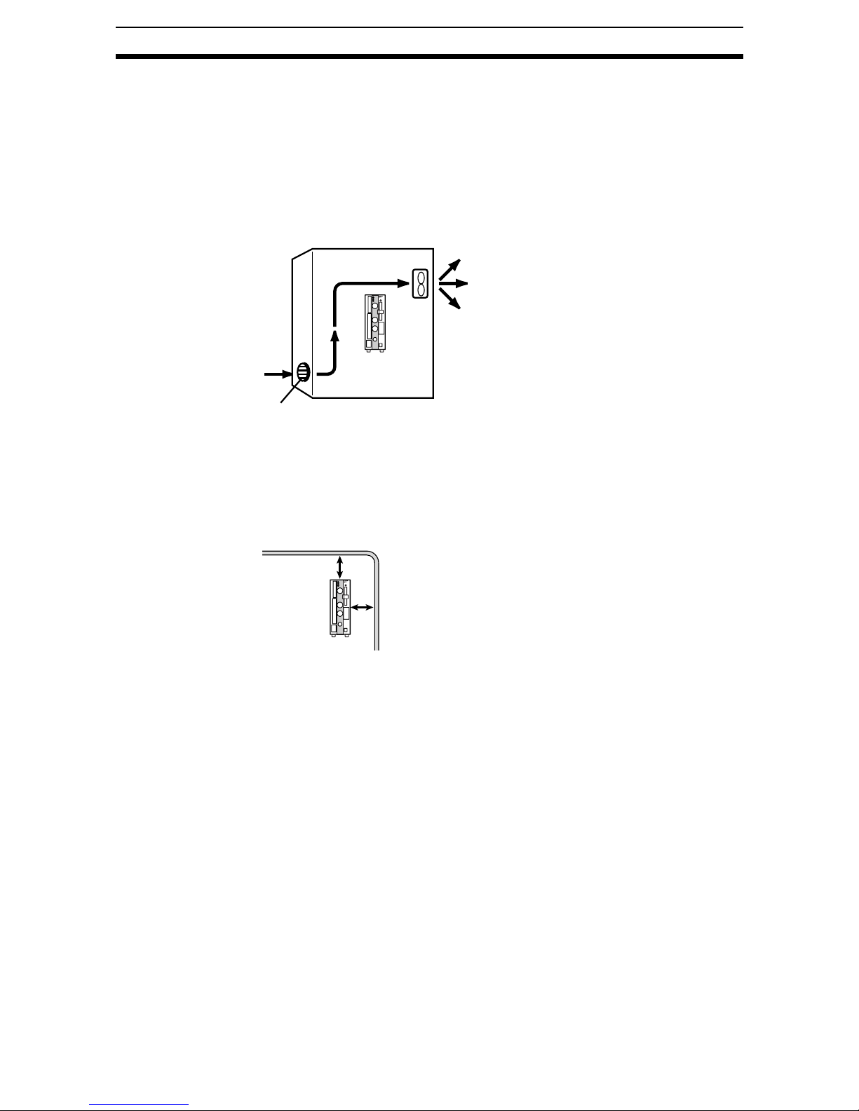
Ambient Temperature
1,2,3... 1. Maintain a minim um clear a nce of 50 mm abo v e an d belo w the F16 0 to im -
prove air circulation.
2. Do not install the F160 immediately above significant heat sources, such
as heaters, transformers, or large-capacity resistors.
3. Do not let the ambient operating temperature exceed 50°C (122°F).
4. Provide a forced-air fan cooli ng or air con diti on ing if the am bie nt tem per a ture is near 50°C (122°F) so that the ambient temperature never exceeds
50°C (122°F).
Control panel
F160
Louver
Noise Resistance
Use the following measures to help increase noise resistance.
1,2,3... 1. Do not install the F160 in a cabinet containing high-voltage equipment.
2. Do not install the F160 within 200 mm of power cables.
Power cable
200 mm min.
200 mm min.
F160
1-1-2 Component Installation and Handling
OMRON Components
Use a Camera, Camera Cable, and Console designed specifically for the
F160.
Connecting Cables
Always turn OFF the F160’s power before connecting or disconnecting a camera or cable.
Handling the Camera
The Camera’s case is connected to th e 0 V li ne in th e i nternal circuits. Observe
the following precautions to prevent noise interference.
1,2,3... 1. Do not ground the Camera.
2. Do not remove the base attached to the Camera.
3. Do not remove the core attached to the F150-VS Camera Cable.
3
Page 17
Installation Precautions Section 1-1
Securing the Video Monitor (When Using the Recommended F150-M09)
Observe the following precautions to prevent noise interference, because the
video monitor case is connected to the 0V line in the internal circuits.
1,2,3... 1. Do not ground the video monitor.
2. Do not ground the metallic part of the connector.
3. Secure t he video monitor w ith plas tic scre ws if i t is bei ng moun ted to a metallic surf ac e .
Touching Signal Lines
To prevent damage from static electricity, use a wrist strap or another device
for preventing electrostatic discharges when touching terminals or signal lines
in connectors.
Removing the Memory Card
Before removing a Memory Card, stop the power supply to the Card or turn
OFF the F160. The Memory Card or the F160 itself may be damaged if a
Memory Card is removed while power is being supplied.
(Stop the power supply to the Memory Card from the menu.)
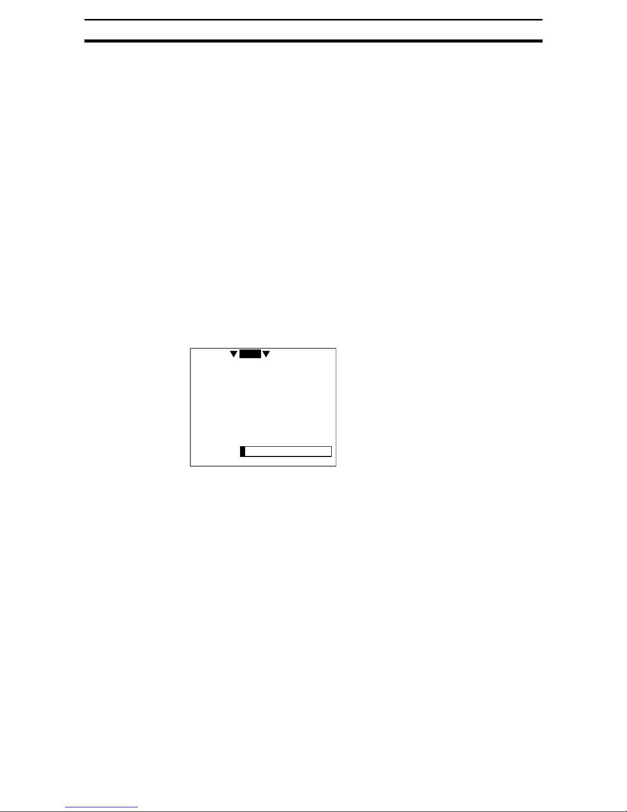
Turning OFF the Power
Do not turn OFF the power while a message is being displayed indicating that
processing is being performed. Data in memory will be corrupted, and the
F160 may not operate correctly the next time it is started.
0.Scn 0 MON
Saving data.
Using the RESET Signal
Do not use the RESET input immediately after power is turned ON. When
using the RESET input to synchronize startup timing, wait at least 1 second
after the F160’s power supply is turned ON before turning ON the RESET signal.
---- ---ms
4
Page 18
Confirming Package Contents Section 1-2
1-2 Confirming Package Contents
Check the contents of the package as soon as you receive the F160. It is
extremely rare for components to be missing, but contact the nearest OMRON
representative if any of the following items are missing.
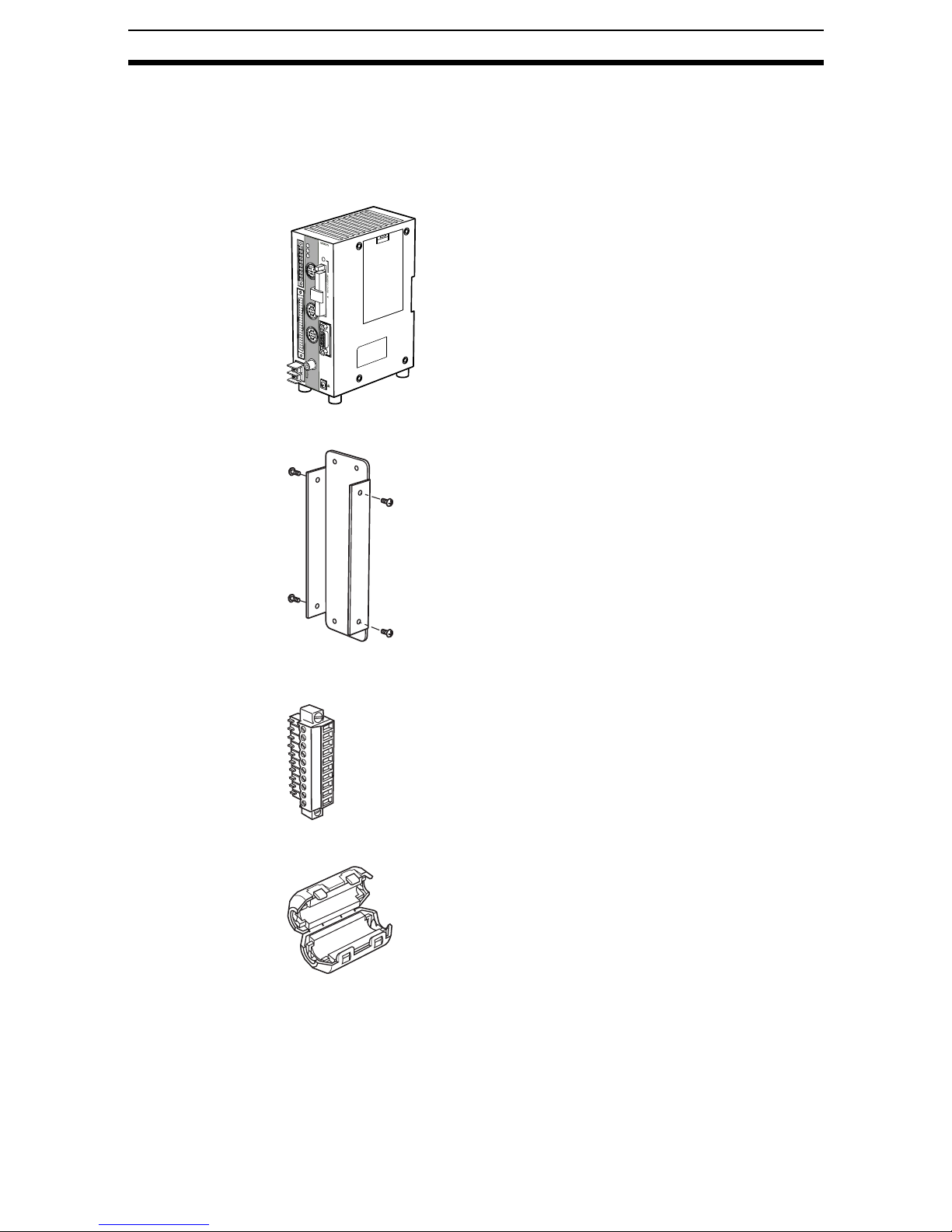
1,2,3... 1. F160 Vision Mate Controller Qty.: 1
F160
S
T
E
POWER
P
V
I
S
I
O
R
E
N
S
E
M
T
C
A
O
T
N
E
RUN
T
R
O
C
L
O
L
M
E
I
N
R
R
ERROR
U
N
E
R
R
O
R
B
U
S
Y
G
A
T
E
O
R
D
O
1
5
C
O
M
O
U
T
C
O
N
S
O
L
E
C
A
M
E
R
A
0
P
A
R
R
S
A
-
2
3
2
C
L
/
4
2
2
L
C
A
E
M
E
R
A
L
1
M
O
N
IT
O
R
+
2
4
V
D
C
1
-
.
2
A
2. Mounting B racket (for rear surface mounting)
Bracket: Qty: 1
Screws (M3 x 6): Qty: 4
3. Connector for I/O Terminals Qty.: 1
(Phoenix Contact model MC1.5/10-STF-3.5)
4. Ferrite Core for F150-VM Monitor Cable Qty.: 1
5. Setup Manual (this manual) Qty.: 1
6. Conversational Menu Operation Manual Qty.: 1
7. Expert Menu Operation Man ual Qty.: 1
8. Communications Reference Qty.: 1
5
Page 19

Product Availability Section 1-3
1-3 Product Availability
Some of the products listed may not be available in some countries. Please
contact your nearest OMRON sales office by referring to the addresses provided at the back of this manual.
6
Page 20

SECTION 2
Installation and Connections
This section shows a basic F160 system configuration and explains how to install and wire the F160.
2-1 Basic System Configuration . . . . . . . . . . . . . . . . . . . . . . . . . . . . . . . . . . . . . . 8
2-2 Component Names and Functions. . . . . . . . . . . . . . . . . . . . . . . . . . . . . . . . . . 10
2-3 Mounting the Controller . . . . . . . . . . . . . . . . . . . . . . . . . . . . . . . . . . . . . . . . . 11
2-3-1 DIN Track Mounting. . . . . . . . . . . . . . . . . . . . . . . . . . . . . . . . . . . . . 11
2-3-2 Rear Surface-mounting . . . . . . . . . . . . . . . . . . . . . . . . . . . . . . . . . . . 12
2-3-3 Side Surface-mounting . . . . . . . . . . . . . . . . . . . . . . . . . . . . . . . . . . . 14
2-3-4 Bottom Surface-mounting. . . . . . . . . . . . . . . . . . . . . . . . . . . . . . . . . 15
2-4 Connecting Peripheral Devices . . . . . . . . . . . . . . . . . . . . . . . . . . . . . . . . . . . . 15
2-4-1 Connecting a Console . . . . . . . . . . . . . . . . . . . . . . . . . . . . . . . . . . . . 16
2-4-2 Connecting a Monitor . . . . . . . . . . . . . . . . . . . . . . . . . . . . . . . . . . . . 16
2-4-3 Connecting a Camera . . . . . . . . . . . . . . . . . . . . . . . . . . . . . . . . . . . . 16
2-5 Overview of Available Cameras . . . . . . . . . . . . . . . . . . . . . . . . . . . . . . . . . . . 16
2-6 Power Supply and Ground. . . . . . . . . . . . . . . . . . . . . . . . . . . . . . . . . . . . . . . . 18
2-6-1 Crimp Terminals and Cables. . . . . . . . . . . . . . . . . . . . . . . . . . . . . . . 18
2-6-2 Ground (Earth) Wiring . . . . . . . . . . . . . . . . . . . . . . . . . . . . . . . . . . . 18
2-6-3 Wiring the Power Supply . . . . . . . . . . . . . . . . . . . . . . . . . . . . . . . . . 19
7
Page 21
Basic System Configuration Section 2-1
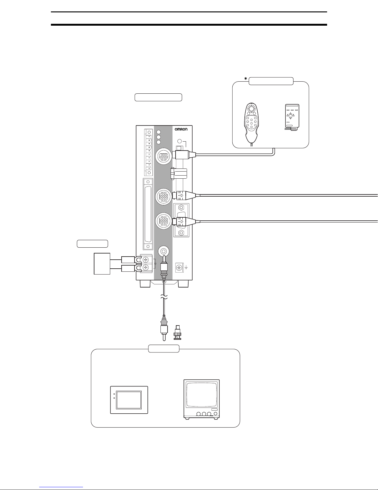
2-1 Basic System Configuration
Precaution The following diagram shows the basic F160 system configuration. Some of
the components shown in the configuration diagram are special OMRON
products that cannot be subst itu ted w ith co mp arable devices . These items are
indicated with an asterisk.
Console
Controller
The F160 performs the image
processing specified by the
user settings and outputs the
measurement results.
POWER
F160
STEP
RESET
COMIN
RUN
ERROR
OR
BUSY
GATE
DO15
COMOUT
RUN
ERROR
CONSOLE
VISION MATE
CONTROLLER
MEMORY CARD
F160-KP
(2-m cable)
F150-KP
(2-m cable)
Power Supply
page 18
Recommended model:
OMRON S82K-05024
Color LCD Monitor
(F150-M05L)
PARALLEL
CAMERA0
RS-232C/422
CAMERA1
MONITOR
+
24VDC
−
Monitor Cable
F150-VM (2 m)
BNC Jack
(Included with the F150-VM.)
Monitors
Monochrome CRT
Video Monitor(F150-M09)
*Camera Cable
F150-VS (3 m)
The Monitor is used to check the
image and display menus when
making settings.
POWER
SYNC
(RCA plug input)
8
(BNC input)
Page 22
Basic System Configuration Section 2-1
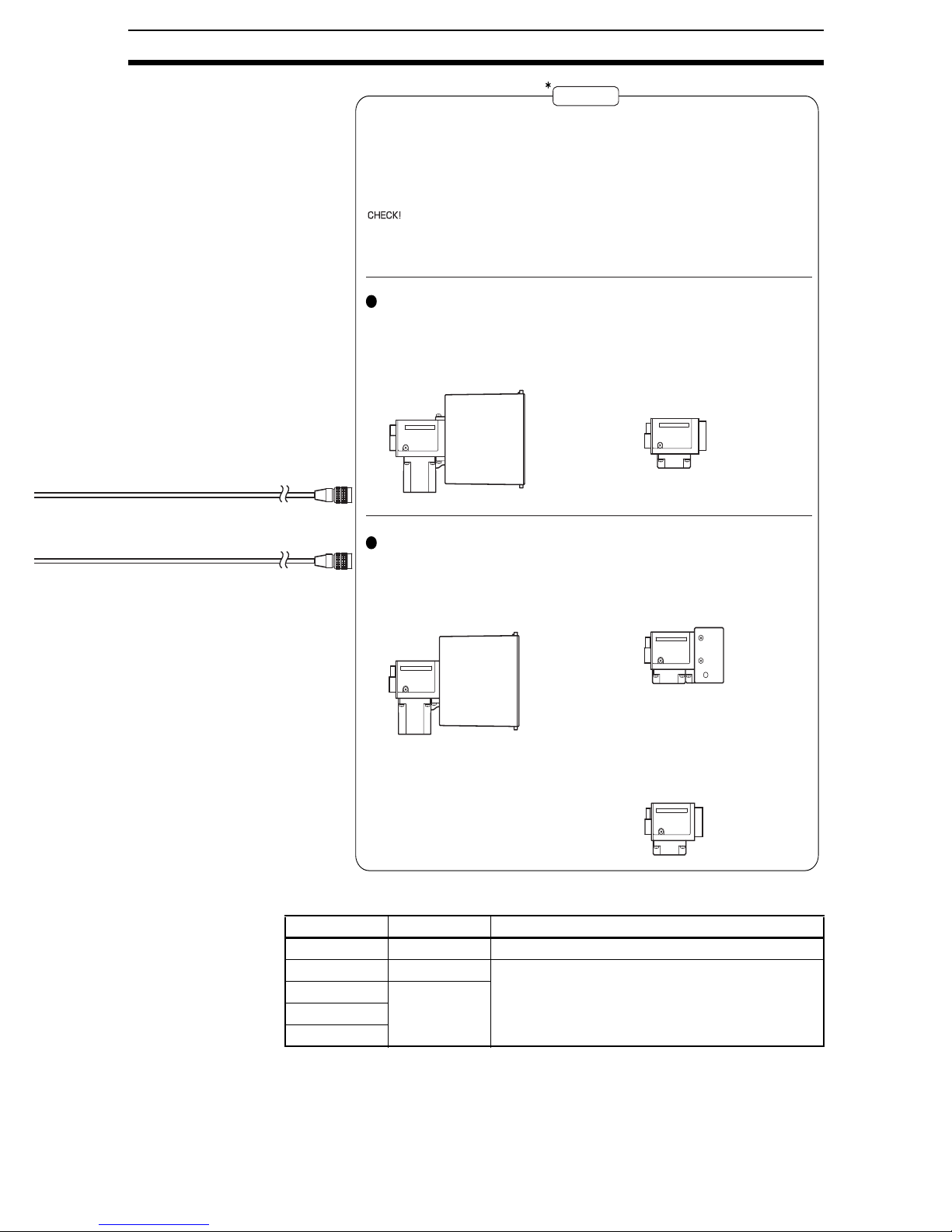
Cameras
Images of measurement objects are obtained using Cameras. Up to 2
Cameras can be connected to an F160, but the 2 Cameras can be used
with the Expert Menu only. Just 1 Camera can be used with the
Conversational Menu.
Two different models of Camera can be connected as long as the Cameras
are of the same type. (The model number prefix (F150 or F160) indicates the
Camera's type, so two Cameras can be connected together if they have the
same prefix.)
Double-speed Cameras
Camera with Intelligent Lighting
F160-SLC20 (20-mm field of vision)
F160-SLC50 (50-mm field of vision)
Camera Only
Use the Camera by itself when the field of vision of
the Camera with Intelligent Light" does not match
the size of the measurement object. A standard
CCTV lens and light source will be needed.
F160-S1
CHECK
F150 Cameras
Camera with Intelligent Lighting
F150-SLC20 (20-mm field of vision)
F150-SLC50 (50-mm field of vision)
Camera with Light
F150-SL20A (20-mm field of vision)
F150-SL50A (50-mm field of vision)
Camera Only
Use the Camera by itself when the field of vision of
the Camera with Intelligent Light" does not match
the size of the measurement object. A standard
CCTV lens and light source will be needed.
F150-S1A
F200-series and F300-series Cameras can also be connected.
Camera type Camera Cable Max. number of Cameras
F200-S F160-VSR3 1 (Connect to camera connector 0.)
F300-S F160-VSR4 2
F300-S2R F160-VSR3
F300-S3DR
F300-S4R
(The 2 cameras must have the same model number.
Only one camera can be connected with the Conversational Menu.)
SeeAlso Refer to page 63 for details on parameter settings.
9
Page 23
Component Names and Functions Section 2-2
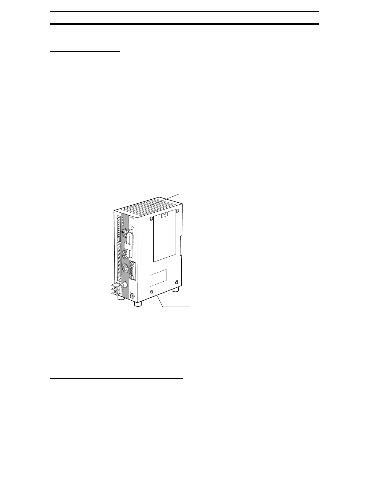
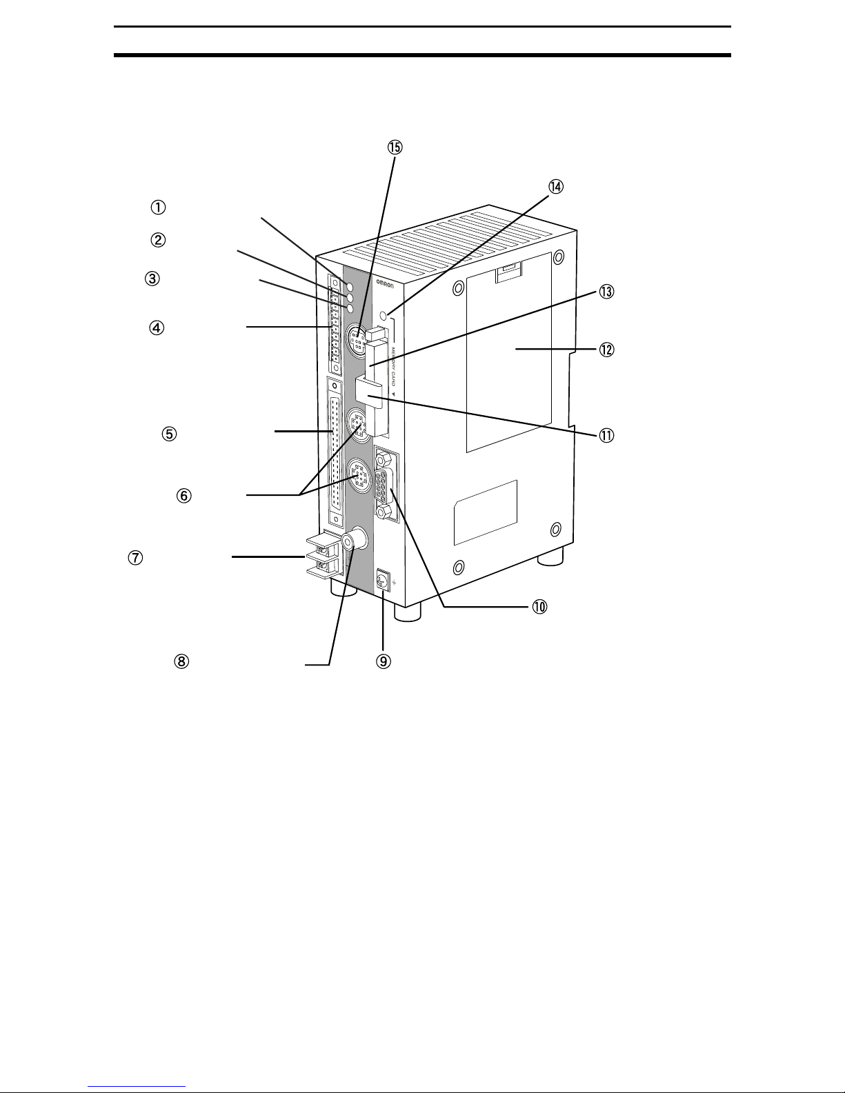
2-2 Component Names and Functions
The following diagram shows the F160 Vision Mate Controller’s major external
components.
Console connector
Memory Card indicator
POWER indicator
RUN indicator
ERROR indicator
I/O terminals
(Control lines)
I/O connector
(Control and data lines)
Camera
connectors
Power supply
terminals
Monitor connector
P
O
W
E
R
U
N
E
R
R
O
C
O
N
S
O
LE
C
A
M
E
R
A
CAMERA 1
MONITOR
+
24V
D
C
-
F160
V
R
IS
IO
N
M
C
A
O
T
N
E
T
R
O
LL
E
R
R
Memory Card slot
Battery cover
0
R
S
-2
3
2
C
/4
2
2
Card lock
S
T
E
P
R
E
S
E
T
C
O
M
IN
R
U
N
E
R
R
O
R
O
R
B
U
S
Y
G
A
T
E
D
O
1
5
C
OM
OUT
PA
R
ALLE
L
RS-232C/RS-422 connector
Ground terminal
1. Lit while power is ON.
2. Lit while t he F160 is in R un Mode.
3. Lit when an error has occurred.
4. Connects the F160 to external devices such as a sync sensor or PLC.
5. Connects the F160 to external devices such as a sync sensor or PLC.
6. Connects to the Camera(s).
7. Connects to the power supply.
8. Connects to the monitor.
9. Connects to the ground wire.
10. Connects the F160 to an external device such as a personal computer or
PLC.
11. This lock se cures the M emory Card so that it does not disco nnect unin tentionally from vibration.
12. Covers the compartment that contains the F160’s battery.
13. This slot recei ves t he Memory Card.
10
Page 24
Mounting the Controller Section 2-3
14. Lit when powe r is being supplied to the Memory Card. (The Memo ry Card
must not be inserted or removed when this indicator is lit.)
15. Connects the F160 to a Console.
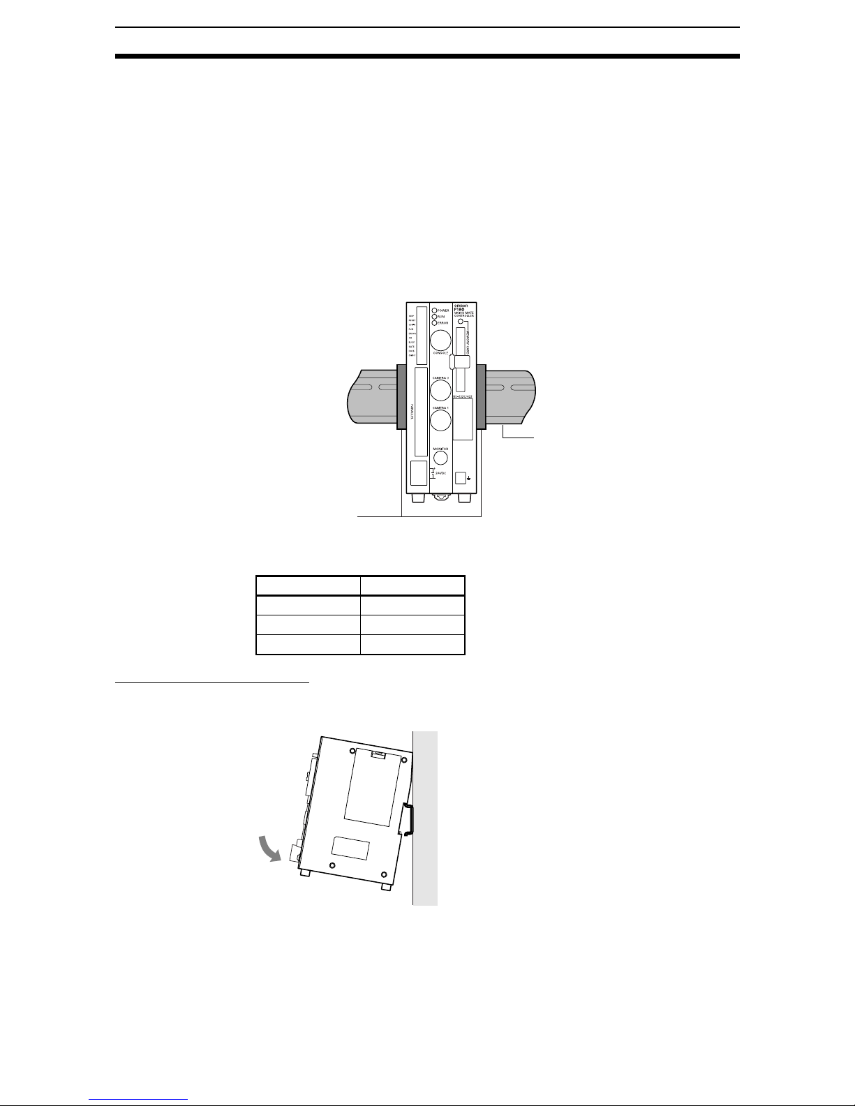
2-3 Mounting the Controller
There are four ways to mount the Vision Mate Controller: DIN Track mounting,
rear surface-mounting, side surface-mounting, or bottom surface-mounting.
2-3-1 DIN Track Mounting
The Vision Mate Controller can be easily mounted to or removed from 35-mm
DIN Track.
DIN Track
PFP-M End Plate
(OMRON)
The following DIN Tracks are available from OMRON.
Model Length
PFP-100N 1 m
PFP-50N 50 cm
PFP-100N2 1 m
Mounting the Controller
Hook the Controller into the DIN Track as shown in the diagram and then
press in at the bottom until the Controller locks into place.
11
Page 25
Mounting the Controller Section 2-3
Removing the Controller
Use a screwdriver to pull the hook down and then pull out the Controller from
the bottom.
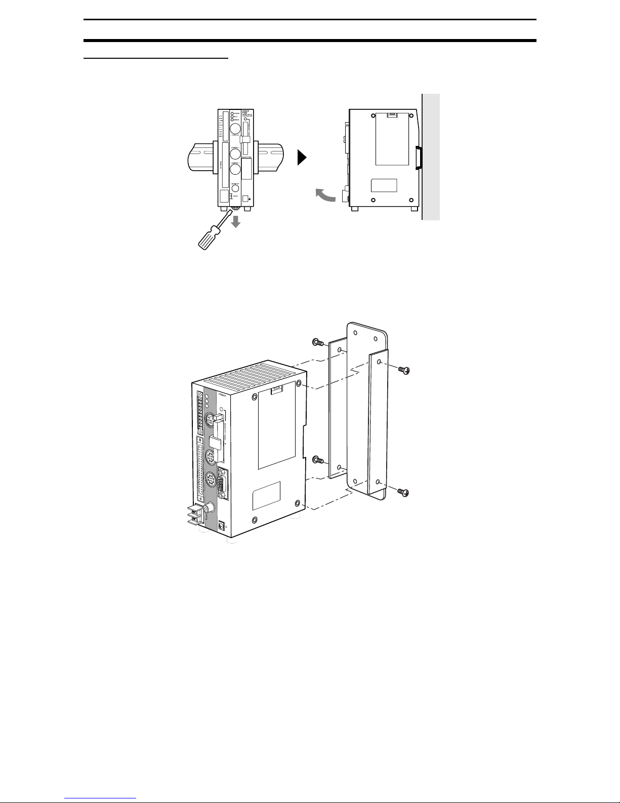
2-3-2 Rear Surface-mounting
1. Attach the mo unting br ac k et to the F16 0 Control ler usi ng the four machine
screws (M3 × 6) included with the bracket.
F
STEP
1
P
6
O
0
W
E
V
R
IS
IO
RESET
N
M
C
A
O
T
N
E
R
T
U
R
N
C
O
RUN
ERRO
BUSY
GATE
OR
DO15
C
O
O
L
M
I
N
R
M
O
U
T
P
A
R
A
L
L
E
L
L
E
R
E
R
R
O
R
C
O
N
S
O
L
E
C
A
M
E
R
A
0
R
S
-23
2C
/4
22
C
A
M
E
R
A
1
M
O
N
IT
O
R
+
24VDC
-
12
Page 26
Mounting the Controller Section 2-3
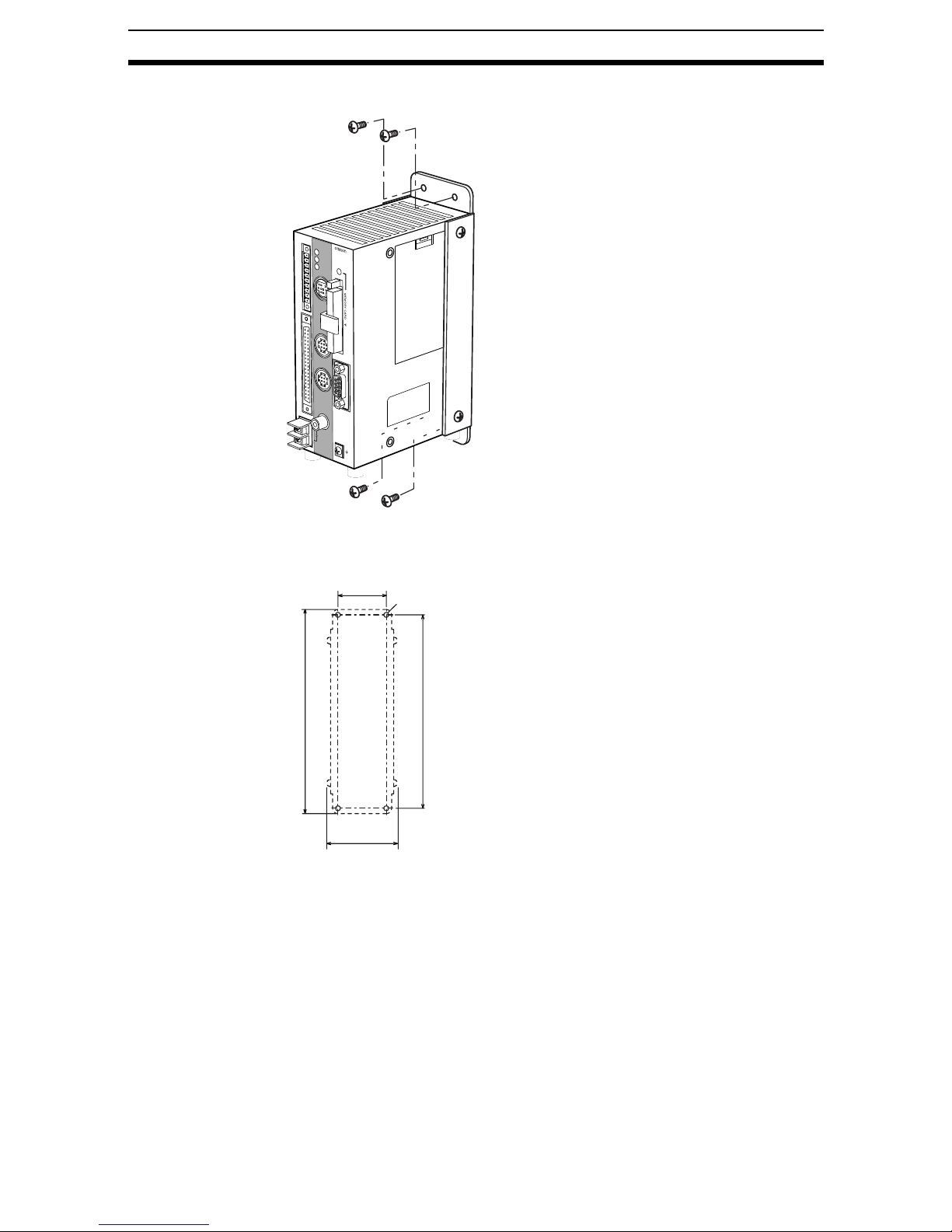
2. Fasten the F160 Controller and Mount ing Br a cket to the mounting surface
with four M4 screws.
F
STE
1
P
P
6
O
0
W
E
V
R
IS
IO
RE
N
SET
M
C
A
O
T
N
E
R
T
U
R
N
C
O
M
R
U
ERROR
BUSY
G
ATE
O
R
D
O15
C
O
M
O
L
L
I
N
N
O
U
T
P
A
R
A
L
L
E
L
E
R
E
R
R
O
R
C
O
N
S
O
L
E
C
A
M
E
R
A
0
R
S
-2
32
C
/422
C
A
M
E
R
A
1
M
O
N
IT
O
R
+
24VDC
-
Use the holes and dimensions shown in the following diagram.
Unit: mm
45±0.2
Four, M4
(190)
180±0.2
(62.2)
13
Page 27

Mounting the Controller Section 2-3
2-3-3 Side Surface-mounting
The F160 Controller can be side-mounted directly to a panel as shown in the
following diagram.
F
STEP
1
P
6
O
0
W
E
V
R
IS
IO
RESET
N
M
C
A
O
T
N
E
R
T
U
R
N
C
R
ER
BUSY
GATE
OR
D
C
O
O
M
UN
RO
O15
O
M
P
A
R
A
L
L
E
L
L
L
I
N
R
O
U
T
E
R
E
R
R
O
R
C
O
N
S
O
L
E
C
A
M
E
R
A
0
R
S-232C
/4
22
C
A
M
E
R
A
1
M
O
N
IT
O
R
+
24VDC
-
Use the holes and dimensions shown in the following diagram.
Unit: mm
(12)
60±0.46
Four, M3 (Screw depth: 4.8 mm max.)
(153)(7)
66.5±0.46 66.5±0.46
(110)
14
Page 28

Connecting Peripheral Devices Section 2-4
2-3-4 Bottom Surface-mounting
F
ST
1
EP
P
6
O
0
W
E
V
R
IS
I
O
RE
N
SET
M
C
A
O
T
N
E
R
T
U
R
N
C
O
R
U
ERR
BUSY
GA
OR
D
O
C
O
O
L
M
I
N
N
OR
TE
15
M
O
U
P
A
R
A
L
L
E
L
L
E
R
E
R
R
O
R
T
C
O
N
S
O
L
E
C
A
M
E
R
A
0
R
S
-23
2C
/4
22
C
A
M
E
R
A
1
M
O
N
IT
O
R
+
24VDC
-
Use the holes and dimensions shown in the following diagram.
Unit: mm
38±0.39
(9)
92±0.54
Four, M4 (Screw depth: 6 mm max.)
2-4 Connecting Peripheral Devices
This section shows how to connect peripheral devices to the F160.
Precaution Always turn OFF the power supply before connecting or disconnecting a
peripheral device’s cable. The peripheral device may be damaged if it is connected while the power is ON.
15
Page 29

Overview of Available Cameras Section 2-5
2-4-1 Connecting a Console
Connect the Console to the F160’s CONSOLE connector. An F160-KP or
F150-KP Console can be connected.
SHIFT
ENT
TRIGESC
CONSOLE
2-4-2 Connecting a Monitor
Connect the monitor cable to the F160’s MONITOR connector, and attach the
enclosed Ferrite Core to the monitor cable. The Ferrite Core should be
attached to the cable approximately 10 mm from the MONITOR connector.
MONITOR
Approx. 10 mm
2-4-3 Connecting a Camera
Connect the camera cable to the F160's CAMERA connector.
CAMERA
Note The connector is capped when the F160 is shipped. When not using the con-
nector, leave the cap in place to protect against dust, dirt, and static electricity.
Ferrite Core
Wrap the cable in one loop
in the Ferrite Core.
2-5 Overview of Available Cameras
The F160 Camera with Light is a special F160 Camera that has a special lens
and light source alread y attac hed. The li ght sourc e and len s are cont ained in a
single unit, so installation is very simple. Just mount the Camera at the proper
distance from the measurement object and it is ready to use.
16
Page 30

Overview of Available Cameras Section 2-5
Camera with Light
Item F150-SL20A F150-SL50A
Field of vision 20 mm
Mounting distance 61 to 71 mm 66 to 76 mm
Relationship
between Camera
and object
20 mm 50 mm 50 mm
Measurement
Mounting distance
object
Field of vision
Lighting precautions None in particular
Camera with Intelligent Lighting
Item F150-SLC20 or F160-SLC20 F150-SLC50 or F160-SLC50
Field of vision 20 mm
Mounting distance 15 to 25 mm 16.5 to 26.5 mm
Relationship
between Camera
and object
Measurement
object
Lighting precautions Use with DIP switch pins 1 and 2 both set
to OFF.
20 mm 50 mm 50 mm
Mounting distance
Field of vision
Use with DIP switch pins 1 and 2 both set
to OFF.
Camera Only
Item F150-S1A or F160-S1
Field of vision and
distance to object
Determine the required field of vision based on the size of the measurement object and
select an appropriate CCTV lens (C mount).
Lighting precautions Provide a light source appropriate for the measurement object.
CHECK Observe the following precautions when using a Camera with Light or Camera
with Intelligent Lighting.
12
O
1
F
F
2
17
Page 31

Power Supply and Ground Section 2-6
• The lens has a fixed focal point. The actual field of vision and focal point
vary from lens to lens, so adjust the distance to the measurement object
after replacing the lens or camera.
• The camera mounting distance listed in the following tables is an approximate value. Mount the Camera so that the distance to the measurement
object can be adjusted easily.
If the object size and field of vision are incompatible, use a standard CCTV
lens and light source.
SeeAlso page 22
2-6 Power Supply and Ground
Wire the power supply and the ground to their respective terminals. Tighten
the screws to a torque of between 0.49 N•m.
After wiring, confirm that the wiring is correct.
2-6-1 Crimp Terminals and Cables
The terminal block uses M3 terminal screws. Use appropriate crimp terminals
for M3 screws, as shown below.
Forked Round
6.2 mm max.
Applicable wire size: In su lated wire of 1.31 to 1.65 mm
2-6-2 Ground (Earth) Wiring
Always connect a ground wire to the F160's ground terminal. To avoid grounding problems, do not share the ground wire with any other devices or wire the
ground to th e building's steel framing.
Use a groundin g point t hat i s as clos e as po ssib le and k ee p the g rou nd wir e as
short as possible.
F160
6.2 mm max.
2
(AWG16 to AWG15)
18
Ground to 100 Ω or less.
Page 32

Power Supply and Ground Section 2-6
2-6-3 Wiring the Power Supply
Wire the Power Supply Unit independently of other devices. In particular, keep
the power supply wired separately from inductive loads. Also, keep the power
supply wiring as shor t as possible (less than 10 m).
Use a power supply that meets the following specifications. We recommend
using OMRON’s S82K-05024 Power Supply.
Item Specification
Output current 1.6 A min.
Power supply voltage
24 VDC
CHECK Use a DC power supply with countermeasures against high voltages (safe
extra low-voltage circuits on the secondary side). If the system must meet UL
standards, use a UL class II power supply.
F160
+10%
/
-15%
+
−
+
24VDC
−
24 VDC
!Caution After wiring, replace the protective cover on the power supply terminals.
19
Page 33

Page 34

SECTION 3
Lenses, Lighting, and Memory Cards
This section provides additional information on CCTV lenses, lighting, and Memory Cards.
3-1 CCTV Lenses. . . . . . . . . . . . . . . . . . . . . . . . . . . . . . . . . . . . . . . . . . . . . . . . . . 22
3-1-1 Optical Chart. . . . . . . . . . . . . . . . . . . . . . . . . . . . . . . . . . . . . . . . . . . 22
3-1-2 Lenses and Lens Diameters. . . . . . . . . . . . . . . . . . . . . . . . . . . . . . . . 23
3-1-3 Extension Tubes . . . . . . . . . . . . . . . . . . . . . . . . . . . . . . . . . . . . . . . . 24
3-2 Lighting . . . . . . . . . . . . . . . . . . . . . . . . . . . . . . . . . . . . . . . . . . . . . . . . . . . . . . 24
3-2-1 Lighting Methods . . . . . . . . . . . . . . . . . . . . . . . . . . . . . . . . . . . . . . . 24
3-3 Memory Card. . . . . . . . . . . . . . . . . . . . . . . . . . . . . . . . . . . . . . . . . . . . . . . . . . 26
3-3-1 Installing a Memory Card . . . . . . . . . . . . . . . . . . . . . . . . . . . . . . . . . 27
3-3-2 Removing the Memory Card. . . . . . . . . . . . . . . . . . . . . . . . . . . . . . . 27
3-3-3 Using Memory Cards in a Personal Computer . . . . . . . . . . . . . . . . . 28
21
Page 35

CCTV Lenses Section 3-1
3-1 CCTV Lenses
When using a Camera without a light (F150-S1A or F160-S1), refer to the following graph to select the appropriate Lens and Extension Tube. The lens will
differ depending on the size of the measurement object and the distance from
the Camera.
3-1-1 Optical Chart
The values in the following chart are appro x im at ion s , and the Camera must be
adjusted after it is mounted.
Lens model: 3Z4S-LE
5,000
3,000
Camera distance A (mm)
2,000
1,000
500
300
200
100
50
4 5 10 20 30 50 100 200 300 500
Field of vision L (mm)
The X axis of the gra ph s ho ws fie ld o f vis io n L (mm), a nd th e Y axis shows the
camera distance A (mm). The curves on the graph show the relationship
between the field of vision and camera distance for each CCTV lens. The values are significantly different for each lens, so double-check the model of the
lens before using the graph. The “t” values indicate the lengths of the Extension Tubes. The value “t0” shows the case where an Extension Tube is not
needed and the value “t5.0” shows the case where a 5-mm Extension Tube is
used.
t: Extension Tube length
22
Page 36

CCTV Lenses Section 3-1
Example
When a 3Z4S-LE C1614A CCTV Lens is being used and a field of vision of
40 mm is needed at the measurement object, a camera distance of 200 mm
and 1-mm Ex tension Tube are required.
Camera
Extension Tube t@ (mm)
Lens
Camera distance A (mm)
Measurement object
Field of vision L (mm)
3-1-2 Lenses and Lens Diameters
Unit: mm
Max. outer dia.
Total length
Lens Focal length Bright-
ness
3Z4S-LE C418DX 4.8 mm F1.8 40.5 mm dia. 35.5 mm --3Z4S-LE B618CX-2 6.5 mm F1.8 48 mm dia. 42 mm
3Z4S-LE C815B 8.5 mm F1.5 42 mm dia. 40 mm M40.5
3Z4S-LE B1214D-2 12.5 mm F1.4 42 mm dia. 50 mm
3Z4S-LE C1614A 16.0 mm F1.4 30 mm dia. 33 mm M27
3Z4S-LE B2514D 25.0 mm F1.4 30 mm dia. 37.3 mm
3Z4S-LE B5014A 50.0 mm F1.4 48 mm dia. 48 mm M46
3Z4S-LE B7514C 75.0 mm F1.4 62 mm dia. 79 mm M58
1"-32UN
-2A
Maximum outer
diameter
30 dia.
Tota l le n gth Filter size
× P0.5
× P0.5
× P0.75
× P0.75
23
Page 37

Lighting Section 3-2
3-1-3 Extension Tubes
One or more Extension Tubes can be inserted between the lens and the Camera to focus the Camera image. Use a combination of one or more of the six
tubes to achieve the required length.
Extension Tube
Model M aximum outer
diameter
3Z4S-LE EX-C6 31 dia. Set of 6 tubes
0.5 mm, 1 mm, 5 mm, 10 mm, 20 mm, and
40 mm
Length: 40 mm 20 mm 10 mm 5 mm 1.0 mm 0.5 mm
Length
Precaution • Do not use the 0.5-mm and 1.0-mm Extension Tubes attached to each
other. Since these Extension Tubes are placed over the threaded section
of the Lens or other Extension Tube, the connection may loosen when
more than one 0.5-mm or 1.0-mm Extension Tube are used together.
• Reinforcement may be required for combinations of Extension Tubes
exceeding 30 mm if the Camera is subject to vibration.
3-2 Lighting
A stable image m us t be obtained to ensure accurate inspe cti on. Us e app ropriate lighting for the application and the measurement object if using a Camera
without a light (F150-S1A or F160-S1).
3-2-1 L ighting Methods
Back Lighti ng
A stable, high-contrast image can be obtained using back lighting.
24
Page 38

Lighting Section 3-2
Applications: Inspection of exterior shape or positioning inspection
Camera
Measurement object
Light source
Reflected Lighting
Ring Lights
Light is shone uniformly on the measurement object.
Applications: Surface inspections
Camera
Light source
Measurement object
Oblique Lighting
Detection can be made utilizing the difference in regular and diffuse reflected
light.
25
Page 39

Memory Card Section 3-3
Applications: Inspections for surface gloss
Camera
Light source
Measurement object
Coaxial Lighting
A stable image can be obtained with few shadows from uneven surfaces on
the measurement object.
Applications: Surface inspections, positioning, and hole inspections of comparatively small objects
Half mirror
3-3 Memory Card
Use a Memory Card to backup data such as settings and image data or
increase the number of scenes when you are using the Scene Group function.
Data from the F160 can be backed up in a personal computer just by inserting
the Memory Card into the computer and copying the desired data.
We recommend the OMRON F160-N64S(S) (64 MB) Memory Card.
CHECK A filler card with no memory is inserted into the F160’s Memory Card slot
before the F160 is shipped. Remove this filler card and install a Memory Card
to use this function.
If Memory Card is not being used, leave the filler card in place to prevent dust
or dirt from entering the Memory Card slot.
Camera
Light source
Measurement object
26
Page 40

Memory Card Section 3-3
MEMORY CARD
F
1
6
0
3-3-1 Installing a Memory Card
1. Open the Memory Card slot’s card lock.
F
1
6
0
MEMORY CARD
CHECK Do not force the lock open; lift the latch gently.
2. Insert the Memory Card.
F
1
6
0
MEMORY CARD
128MB
3. Close the card lock to secure the Memory Card.
3-3-2 Removing the Memory Card
1. Stop the power supply to the Memory Card or turn OFF the F160.
SeeAlso Refer to the Conversational Menu Operation Manual or th e Exper t Menu
Operation Man ual for details on turning OFF the power supply to the Mem-
ory Ca rd.
2. Verify that the Memory Card indicator is not lit.
F
1
6
0
Memory Card
MEMORY CARD
indicator
27
Page 41

Memory Card Section 3-3
MEMORY CARD
F
1
6
0
Precaution
Do not remov e the Me mory Card if the Mem ory Card indi ca tor i s lit. Do ing
so may damage the Memory Car d or the F160 itself.
3. Open the card lock.
Eject button
4. Press the eject button over the Memory Card slot.
5. Pull the Memory Card straight out from the slot.
3-3-3 Using Memory Cards in a Personal Computer
The F160’s Memory Cards can be used in a personal computer with a PC
Card drive (PCMCIA 2.0 or higher, type II compatible) or “Compact Flash”
drive.
The Memory Card must be inserted into a PC Card Adapter in order to be
used in a PC Card drive. We recommend the OMRON HMC-AP001 PC Card
Adapter.
PC Card
Adapter
28
Page 42

SECTION 4
Connecting External Devices
This section describes how to conne ct external devices through a parallel interface (the I/O terminals or I/O
connector) or serial interface (the RS-232C/RS-422 connector).
4-1 Connecting through the Parallel Interface. . . . . . . . . . . . . . . . . . . . . . . . . . . . 30
4-1-1 I/O Terminal Connections. . . . . . . . . . . . . . . . . . . . . . . . . . . . . . . . . 30
4-1-2 I/O Connector Connections . . . . . . . . . . . . . . . . . . . . . . . . . . . . . . . . 31
4-1-3 I/O Specifications . . . . . . . . . . . . . . . . . . . . . . . . . . . . . . . . . . . . . . . 33
4-2 Connecting through the Serial Interface . . . . . . . . . . . . . . . . . . . . . . . . . . . . . 34
4-2-1 Connection Examples . . . . . . . . . . . . . . . . . . . . . . . . . . . . . . . . . . . . 35
4-2-2 Connector . . . . . . . . . . . . . . . . . . . . . . . . . . . . . . . . . . . . . . . . . . . . . 36
4-2-3 Wiring . . . . . . . . . . . . . . . . . . . . . . . . . . . . . . . . . . . . . . . . . . . . . . . . 36
4-2-4 Connection . . . . . . . . . . . . . . . . . . . . . . . . . . . . . . . . . . . . . . . . . . . . 37
29
Page 43

Connecting through the Parallel Interface Section 4-1
4-1 Connecting through the Parallel Interface
This section explains how to connect I/O to the F160 through its parallel interface to input signals such as measurement triggers or output signals such as
measurement results.
Either the I/O terminals or I/O connector can be used for the parallel interface.
The I/O terminals and I/O connector cannot be used simultaneously.
I/O Terminals
When the required control signals are being connected to the I/O terminals,
attach the control wires to the included connector (Phoenix MC1.5/10-STF-
3.5) and then inser t the connector into the F160.
I/O Connector
When you want to use the parallel interface to input commands and output
measurement results, prepare a parallel I/O cable and connect it to the I/O
connector . R ef er t o the Communications Reference Manual for details on communications settings and I/O formats.
4-1-1 I /O Terminal Connections
Wire the cable carrying the control signals to the connector that was included
with the F 160 and ins ert t he connect or into th e F160. The foll owing diagram
shows the I/O allocation of the F160’s I/O terminals. Just wire the terminals
that are needed.
CONSOLE
F160
ERROR
STEP
RESET
COMIN
RUN
ERROR
OR
BUSY
GATE
DO15
COMOUT
(Input: Measurement trigger signal)
(Input: Restarts the F160.)
(Common for input terminals)
(Output: ON for measurement mode)
(Output: ON when error occurred)
(Output: Combined judgement result)
(Output: ON while processing)
(Output: ON for set output time)
(Output: Measurement results)
(Common for output terminals)
STEP
RESET
COMIN
RUN
ERROR
OR
BUSY
GATE
DO15
COMOUT
(See note.)
Note 1. COMOUT is connected to COMOUT1 and COMOUT3 of the I/O connec-
tor.
2. Use wire of cross-sectional area 0.14 to 1.5 mm
2
(AWG 24 to AWG 16)
with a cable length not exceeding 30 m.
Precaution Do not input the RESET input immediately after turn ing ON the power. When
using RESET input to synchro nize startup timing, wait at least 1 s after turning
ON the F160’s power supply before turning ON the RESET signal.
CHECK Use a DC power supply with countermeasures against high voltages (safe
extra low-voltage circui ts on the s ec ond ary si de) for the COMIN terminal. If the
system must meet UL standards, use a UL class II power supply.
30
Page 44

Connecting through the Parallel Interface Section 4-1
Wiring the Connector
1. Use a flat-b lad e precisi on scre wd rive r to loosen the con necto r’ s set s crew.
Counter-clockwise
2. Insert the signal wire.
3. Tighten the set screw to secure the wire. Tighten to a torque of 0.22 to
0.25 N•m.
Clockwise
4. Insert the connector into the F160.
5. Tighten the connector’s mounting screws. Tighten to a torque of 0.22 to
0.25 N•m.
4-1-2 I/O Connector Connections
Use an F160-VP Parallel I/O Cable (sold separately) to connect to the F160’s
I/O connector. Align the connectors and insert the cable’s connector straight
31
Page 45

Connecting through the Parallel Interface Section 4-1
into the F160’s I/O connector. Tighten the connector’s mounting screws to
secure the connection.
F160
F160-VP Parallel I/O Cable (2 m)
A1
CAMERA1
A20
B1
RS-232C/422
B20
Wire color
FG terminals
Marking
(Ground to 100 Ω or less.)
Precaution • Turn OFF the power supply before connecting or disconnecting the Paral-
lel I/O Cable. Peripheral devices may be damaged if the cable is connected or disconnected with the power ON.
• A cover is screwed onto the connector when the F160 is shipped. When
not using the I/O connector, leave the cover in place to protect against
dust, dirt, and static electricity.
Pin Signal Wire color Marking Function
A1 RESET Light brown ■ (black) Restarts the F160.
A2 STEP Yellow ■ (black) Measurement trigger signal input
A3 DI0 Green ■ (black) Command input
A4 DI2 Gray ■ (black)
A5 DI4 White ■ (black)
A6 DI6 Light brown ■■ (black)
A7 DI8 Yellow ■■ (black)
A8 STGOUT0 Green ■■ (black) Strobe trigger 0 output
(See note 1.)
A9 RUN Gray ■■ (black) ON while in Run Mode
A10 BUS Y White ■■ (blac k ) ON during processing
A11 OR Light brown ■■■ (black) Combined judgement result
A12 DO0 Yellow ■■■ (black) Data output
A13 DO2 Green ■■■ (black)
A14 DO4 Gray ■■■ (black)
A15 DO6 White ■■■ (black)
A16 D O8 Light brown ■■■■ (black)
A17 DO9 Yellow ■■■■ (black )
A18 D O11 Green ■■■■ (black)
A19 DO13 Gray ■■■■ (black)
A20 DO15 White ■■■■ (black)
B1 COMIN Light brown ■ (red) Common for input signals
B2 DSA Yellow ■ (red) Data send request signal input
B3 DI1 Green ■ (red) Command input
B4 DI3 Gray ■ (red)
B5 DI5 White ■ (red)
B6 DI7 Light brown ■■ (red)
B7 DI9 Yellow ■■ (red)
32
Page 46

Connecting through the Parallel Interface Section 4-1
Pin Signal Wire color Marking Function
B8 STGOUT1 Green ■■ (red) Strobe trigger 1 output
(See note 1.)
B9 ERROR Gray ■■ (red) ON when an error occurred.
B10 GATE White ■■ (red) ON for the set output time.
B11 C OMO UT 1 Light brown ■■■ (red) Common for control signals
(See note 2.)
B12 DO1 Yellow ■■■ (red) Dat a output
B13 DO3 Green ■■■ (red)
B14 DO5 Gray ■■■ (red)
B15 DO7 White ■■■ (red)
B16 C OMO UT 2 Light brown ■■■■ (red) Common for DO0 to DO7
B17 DO10 Yellow ■■■■ (red) Data output
B18 D O12 Green ■■■■ (red)
B19 DO14 Gray ■■■■ (red)
B20 COMOUT3 White ■■■■ (red) Common for DO8 to DO15
Note
1. Use the STGO UT0 or STGOUT1 sig nal when you want to conn ect a strobe
device to the F160.
SeeAlso For details, refer to page 64.
2. Pins A8 to A11 and B9 to B10 are for control signals.
Precaution Do not input the RESET input immediately after turn ing ON the power. When
using RESET input to synchro nize startup timing, wait at least 1 s after turning
ON the F160’s power supply before turning ON the RESET signal.
CHECK Use a DC power supply with countermeasures against high voltages (safe
extra low-voltage circui ts on the s ec ond ary si de) for the COMIN terminal. If the
system must meet UL standards, use a UL class II power supply.
Making a Parallel I/O Cab le
A parallel I /O ca ble can be as sembled u sin g th e con necto r an d cover li sted i n
the following table or equivalent components. Keep the cable length less than
30 m.
Component Manufacturer Model number
Connector Fujitsu FCN-361J040-AU
Cover Fujitsu FCN-360C040-B
CHECK Double-check the connector wiring for mistakes before turning ON the power
supply for the first time.
4-1-3 I/O Specifications
Input Specifications
Item Specification
Model F160-C10E (NPN mode) F160-C15E (PNP mode)
Input voltage 12 to 24 VDC
ON current 5 to 15 mA
ON voltage 8.8 V max.
OFF current 0.1 mA max.
OFF voltage 4.5 V min.
ON delay RESET input: 10 ms max.
Other inputs: 0.5 ms max.
10%
33
Page 47

Connecting through the Serial Interface Section 4-2
Item Specification
OFF delay RESET input: 15 ms max.
Other inputs: 0.7 ms max.
Internal circuits
COM IN
+
Input
terminal
Input
terminal
COM IN
Output Specifications
Item Specification
Model F160-C10E (NPN mode) F160-C15E (PNP mode)
Output voltage 12 to 24 VDC
Load current 45 mA max.
ON residual voltage 2 V max.
OFF leakage current 0.1 mA max.
Internal circuits
10%
Output terminal
Load
COM OUT
+
CHECK The I/O contacts are shared by the I/O terminals and I/O connector. The fol-
lowing diagram shows the wiring diagram for the STEP signal as an example.
I/O terminals
COMIN
STEP
COM OUT
Load
Output terminal
I/O connector
4-2 Connecting through the Serial Interface
The F160’s serial interface (RS-232C/RS-422 connector) can be used to connect input signals such as measurement triggers or output signals such as
measurement results. Additionally, data that has been set in the F160 can be
backed up in a personal computer.
Refer to the Communications Reference Manual for details on communica-
tions settings and I/O formats.
34
COMIN
STEP
Page 48

Connecting through the Serial Interface Section 4-2
4-2-1 Connection Examples
1:1 Connection (No-protocol, Menu Operation)
RS-232C cable
F160
Multi-drop Connection (No-protocol)
Communications between one computer and several F160s is possible using
Link Adapters.
RS-422 cable
RS-422 cable
RS-422
cable
Link Adapter
OMRON
3G2A9-AL004-E
recommended
Link Adapter Link Adapter
RS-422 cable
Computer
31 Units max.
Computer
Link Adapter
OMRON
B500-AL001
recommended
F160
1:1 Connection (Host Link)
F160
F160
RS-232C cable
F160
PLC
35
Page 49

Connecting through the Serial Interface Section 4-2
4-2-2 Connector
The F160’s RS-232C/RS-422 Connector is a 9-pin D-SUB female connector.
The pin allocation is shown below.
9
8
7
6
Pin Signal Name
1 FG Protective frame ground
2 SD For RS-232C
3RD
4 NC Not connected
5 RDB(+) For RS-422
6 RDA(-)
7SDB(+)
8SDA(-)
9 GND Signal ground
5
4
3
2
1
The following plug and hood are recommended and are available from
OMRON.
Model Model No.
Plug XM2A-0901
Hood XM2S-0911
4-2-3 Wiring
RS-232C Wiring
The maximum cable length is 15 m for RS-232C or RS-422
Signal
SD
RD
GND
F160
Pin
2
3
9
Use only shielded cable.
External device
Pin
Signal
SD
RD
GND
RS/CS control
cannot be used.
36
Page 50

Connecting through the Serial Interface Section 4-2
RS-422 Wiring
F160
Signal
RDB
RDA
SDB
SDA
GND
Pin
5
6
7
8
9
Use only shielded cable.
Note Pin numbers on the external device will depend on the device being con-
nected. Refer to the manual for the personal computer or PLC being connected.
External device
Pin
Signal
RDB
RDA
SDB
SDA
GND
4-2-4 Connection
Align the connector with the socket and press the connector straight into
place. Tighten the two mounting screws to secure the connector.
F160
Precaution • Always turn OFF the power supply before connecting or disconnecting
cables. The peripheral device may be damaged if connected or disconnected with the pow er supply turned ON.
• The connector is capped when the F160 is shipped. When not using the
serial interface, leave the cap in place to protect against dust, dirt, and
static electricity.
37
Page 51

Page 52

SECTION 5
Troubleshooting and Maintenance
This section provide s tabl es to help identify and correc t hardware errors that may occur with the F160 as well as
information on maintenance and periodic inspections.
5-1 Troubleshooting. . . . . . . . . . . . . . . . . . . . . . . . . . . . . . . . . . . . . . . . . . . . . . . . 40
5-1-1 Connection Errors . . . . . . . . . . . . . . . . . . . . . . . . . . . . . . . . . . . . . . . 40
5-1-2 Menu Operation Errors . . . . . . . . . . . . . . . . . . . . . . . . . . . . . . . . . . . 40
5-1-3 Parallel Interface Errors. . . . . . . . . . . . . . . . . . . . . . . . . . . . . . . . . . . 40
5-1-4 Serial Interface Errors . . . . . . . . . . . . . . . . . . . . . . . . . . . . . . . . . . . . 41
5-1-5 Cabling Errors. . . . . . . . . . . . . . . . . . . . . . . . . . . . . . . . . . . . . . . . . . 41
5-2 Maintenance. . . . . . . . . . . . . . . . . . . . . . . . . . . . . . . . . . . . . . . . . . . . . . . . . . . 41
5-2-1 Replacing the Light. . . . . . . . . . . . . . . . . . . . . . . . . . . . . . . . . . . . . . 41
5-2-2 Replacing the Battery . . . . . . . . . . . . . . . . . . . . . . . . . . . . . . . . . . . . 43
5-3 Regular Inspections . . . . . . . . . . . . . . . . . . . . . . . . . . . . . . . . . . . . . . . . . . . . . 44
5-4 Specifications. . . . . . . . . . . . . . . . . . . . . . . . . . . . . . . . . . . . . . . . . . . . . . . . . . 45
5-5 F200/F300 Camera Parameters . . . . . . . . . . . . . . . . . . . . . . . . . . . . . . . . . . . . 63
5-6 Connecting a Strobe Device . . . . . . . . . . . . . . . . . . . . . . . . . . . . . . . . . . . . . . 64
39
Page 53

Troubleshooting Section 5-1
5-1 Troubleshooting
5-1-1 Connection Errors
Problem Probable cause
The POWER indicator is not lit. The Power Supply is not connected properly.
The supply voltage is not 24 VDC
The Video Monitor is blank. The power to the Video Monitor is not ON.
The Monitor Cable is not connected properly.
The Video Monitor is malfunctioning.
When using an LCD Monitor, the power supply capacity is insufficient.
The Video Monitor image is not
clear.
Cannot make key inputs from the
Console.
Camera images do not appear on
the screen (for Cameras with Light
Source).
Camera images do not appear on
the screen (when a standard CCTV
lens and lighting are used).
The indicators do not turn ON (for
Cameras with Light Source).
There is electrical noise entering from the power supply or cables.
The Monitor Cable is not correctly connected.
The Console Cable is not correctly connected.
The Camera Cable is not correctly connected.
The lighting cable is not properly connected to the Camera.
The lens cap has not been removed.
The Camera Cable is not properly connected.
The lens iris is opened or closed too far.
The shutter speed is not suitable.
The lighting method is not suitable.
The lighting cable is not correctly connected to the Camera.
Power is not being supplied to the F160.
When using a Camera with Intelligent Lighting, the DIP switch pins are not
set to 0.
+10%
/
-15%
.
5-1-2 Menu Operation Errors
Problem Probable cause
The measurement results are not
displayed on the Video Monitor.
The F160 is not in Monitor or Run mode.
5-1-3 Parallel Interface Errors
Problem Probable cause
Trigger signals (input signals) are
not received.
Signals cannot be output externally. The trigger signal has not been input.
The cables are not correctly wired.
The signal line is disconnected.
The status of communications can be checked with the I/O monitor.
The F160 is not in Monitor or Run mode.
The cables are not correctly wired.
The signal line is disconnected.
The status of communications can be checked with the I/O monitor.
The F160 is not in Run mode.
40
Page 54

Maintenance Section 5-2
5-1-4 Serial Interface Errors
Problem Probable cause
No communications are possible. The cables are not correctly wired.
The F160’s communications specifications do not match those of the
external device.
The communications mode was not selected under System/Communica-
tions settings/Serial.
Select Normal, Host link, or Menu operations under RS-232C/Operat-
ing mode. (Normal is no-protocol.)
The status of communications can be checked with the I/O monitor.
The Unit operates well initially, but
after a while there is no response
from the F160.
Cannot perform menu operations
from the computer.
The reception buffer on the external device (e.g., computer) is full. Check
that settings allow the data to be properly received.
The communications mode was not set to Me nu operations in the Sys-
tem/Communications settings/Serial settings.
5-1-5 Cabling Errors
Problem Probable cause
A recommended OMRON RS-232C
cable is not being used.
One of the following OMRON cables can be used. Select a cable that
works with the device being connected.
Connecting to a PC/AT or compatible computer (9-pin connector)
• XW2Z-200S-V (2 m)
• XW2Z-500S-V (5 m)
Connecting to a SYSMAC device (9-pin connector)
• XW2Z-200T (2 m)
• XW2Z-500T (5 m)
5-2 Maintenance
5-2-1 Replacing the Light
• The Light will gradua lly lose brig htness over time (abou t 20% loss after
1,500 hours of use). Replace the Light after about 1,500 hours of use.
• Replace the Light if it is damaged or not fully functional.
41
Page 55

Maintenance Section 5-2
F150-SL20A/SL50A
Use the following procedure to replace a Light with the F150-LT10A Light.
(The F150-LT10A cannot be connected to the older F150-S1 Camera.)
Camera base
2
3
Hold this part when
removing the Cable.
1
4
Light
Lighting connector
1. Disconnec t the li ght cab le fro m the l ight co nnector o n the b ack of the Camera.
2. Remove the light cable from the slot in the camera base.
3. Remove the two screws securing the Light.
4. Remove the Light from the Camera.
5. Reverse steps 1 through 4 when installing the Lens and Light.
Camera cable
connector
Precaution Do not disassemble the Lens. Disassembly can damage the Lens.
F150-SLC20/SLC50 or F160-SLC20/SLC50
Use the following procedure to replace a Light with an F150-LTC20 (20-mm
field of vision) or F150-LTC50 (50-mm field of vision) Light.
5
3
Camera base
2
Light
4
1
Hold this part when
removing the Cable.
1. Disconnec t the li ght cab le fro m the l ight co nnector o n the b ack of the Camera.
2. Remove the light cable from the slot in the camera base.
3. Remove the two screws securing the Light at the top.
4. Remove the two screws securing the Light at the bottom.
42
Page 56

Maintenance Section 5-2
5. Remove the Light from the Camera.
6. Reverse steps 1 through 4 when installing the Lens and Light.
Precaution Do not disassemble the Lens. Disassembly can damage the Lens.
CHECK When you want to use the Camera alo ne witho ut c on nec tin g an Intelligent
Lighting, use M2 × 3 screws in the bottom of the Camera instead of the
long screws removed in step 4. The screws removed in step 3 are not
needed.
5-2-2 Replacing the Battery
The F160 contains a battery that backs up the time and date information.
When the battery is nearly discharged, the message “BATTERY LOW” will be
displayed at startup. Replace the battery with an OMRON 3Z49-BAT1 Battery.
Dispose of the spent battery properly.
CHECK • Always turn OFF the power supply before replacing the battery.
• The F 16 0' s cl ock wil l be r e se t i f t he new bat t ery is not c on n ec ted w it hi n 2
minutes of removing the spent battery.
If the clock is inadvertently reset, the time and date will have to be set
again.
SeeAlso Refer to the Conversational Menu Operation Manual or th e Exper t Menu
Operation Manual for details.
Replacement Procedure
1. Open the batte ry cover on the side of the F160. The cover can be opened
2. The battery is mounted to the inside of the battery cover. Hold the battery
with a small flat-blade screwdriver.
F160
S
T
E
P
P
O
W
E
V
R
IS
IO
R
E
N
S
M
E
T
C
A
O
T
N
E
R
T
U
R
N
O
C
L
O
L
M
E
I
N
R
R
E
U
N
R
R
O
R
E
R
R
O
R
O
R
B
U
S
Y
G
A
T
E
D
O
1
5
C
O
M
O
U
T
C
O
N
S
O
L
E
C
A
M
E
R
A
0
P
A
R
R
S
A
-2
3
2
C
L
/4
2
2
L
CAMERA 1
E
L
connector by its base and pull it off.
2.
F160
S
T
E
P
P
O
W
E
V
R
IS
IO
R
E
N
S
M
E
T
C
A
O
T
N
E
R
T
U
R
N
O
C
L
O
L
M
E
I
N
R
R
E
U
N
R
R
O
R
E
R
R
O
R
O
R
B
U
S
Y
G
A
T
E
D
O
1
5
C
O
M
O
U
T
C
O
N
S
O
L
E
C
A
M
E
R
A
0
P
A
R
R
S
A
-2
3
2
C
L
/4
2
2
L
CAMERA 1
E
L
3.
Binding band
3. Cut the bi nding band t hat secur es the battery and re mov e it from the cov er .
4. Reverse steps 1 through 3 to install the new battery. Use the new binding
band included with the new battery to attach it to the battery cover.
43
Page 57

Regular Inspections Section 5-3
!Caution
Do not short the battery terminals, recharge the battery, disassemble, crush,
or dispose of the battery in fire. Doing so may cause the battery to start a fire,
leak, or explode.
5-3 Regular Inspections
To maintain the F160 in the best condition, perform the following regularly.
• Clean the Lens and LED indicators with a lens-cleaning wipe or blow off
dust with an aerosol air sprayer.
• Lightly wipe off dirt with a soft cloth.
Inspection point Details To ols required
Pow er supply The voltage measured at the power supply
terminals must be 24 VDC
Ambient temperature
Ambient humidity The operating ambient humidity inside the
Installation Each component must be firmly secured.
Indicators All indicators must light when the power is
The operating ambient temperature inside
the cabinet must be between 0 and 50
cabinet must be between 35% and 85%.
Each cable connector must be correctly
inserted and locked.
The Cameras must be firmly secured.
The camera lens mounts must be firmly
secured.
turned ON.
Verify that a through-image is displayed.
When using an Intelligent Lighting, verify
that the light level settings are set to their
maximum values.
+10%
/
-15%
Circuit tester
.
Thermometer
°C.
Hygrometer
Phillips screwdriver
---
Precaution • Turn OFF the power and take safety precautions before conducting
inspections . Ele ctrica l sh ock can result from attemp tin g s afety inspections
with the power turned ON.
• Do not use thinners or benzene to clean the F160. They will damage
F160 components.
44
Page 58

Specifications Section 5-4
5-4 Specifications
This section provides the specifications and dimensions of the F160 and its
peripheral devices.
F160-C10E/C15E Vision Mate Controller
Unit: mm
12
1537
66.5 66.5
38
Four holes,
10.2 dia.
Model F160-C10E F160-C15E
Input/Output type NPN PNP
Supply voltage 20.4 to 26.4 VDC
Current consumption 1.6 A max.
Insulation resistance 20 M
Dielectric strength 1,000 VAC, 50/60 Hz between all DC external terminals and GR terminal (with internal
Leakage current 10 mA max.
Noise resistance 2,000 V; pulse width: 50 ns; rise time: 5 ns (pulse)
Vibration resistance
Shock resistance
Ambient temperature Operating: 0 to 50
Ambient humidity Operating and storage: 35% to 85% (with no condensation)
Ambient environment No corrosive gases
Ground Class 1 (Ground resistance 100
Degree of protection IEC60529 IP20 (in-panel)
Case material ABS/PC
Weight Approx. 570 g (Controller only)
992
Item Specification
60
110
internal surge absorber removed)
surge absorber removed)
Burst continuation time: 15 ms; Period: 300 ms
10 to 150 Hz; half-amplitude: 0.35 mm; maximum acceleration: 50 m/s
minutes each in 3 directions (except for bottom surface-mounting.)
150 m/s
Storage: -25 to 65
Four M3 taps,
Depth 4.8
11
1.8
Four M4 taps,
Depth 6
Ω min. between all DC external terminals and GR terminal (100 VDC Megger, with
2
, 3 times each in 6 directions
°C (with no condensation)
°C (with no condensation)
56
Ω max.)
Four M3 taps,
Depth 4.8
115 min.
60
2
, 10 times for 8
12
66.566.5
45
Page 59

Specifications Section 5-4
F150 Cameras
Cameras with Light
■ F150-SL20A/SL50A
39
67
27
431
(70.5)
Unit: mm
25.4
F150-LT10A Light
(50.25)
16.75±1.1
20±1.3(40.25)
3.8 dia.
Two M4 taps, Depth 8
1/4-20UNC tap,Depth 8
(6.75)
46
Page 60

Specifications Section 5-4
Cameras with Intelligent Lighting
■ F150-SLC20
2.5
12
70
12
F150-LTC20 Light
73
40
Unit: mm
(85)
70
2.5
12
31
40
12
42.5
(96.25)
(86.25)
30.5
16.75±1.1
20±1.3
(10)
4 dia.
Two M4 taps, Depth 10
1/4-20UNC tap,Depth 10
(6.75)
25
47
Page 61

Specifications Section 5-4
F150-SLC50
■
90
16
90
31
60
16
F150-LTC50 Light
Unit: mm
2.52.5
52.5
1616
80
(103.25)
40
30.5
16.75±1.1
(85)
(10)
25
4 dia.
Two M4 taps, Depth 10
(93.25)
20±1.3
1/4-20UNC tap,Depth 10
(6.75)
48
Page 62

Specifications Section 5-4
Camera Only
■ F150-S1A
(14.5)
(15.5)
1"-32UN-2A
(C mount)
8
31.25±2
21.25±2
48
(40)
30.5
20±0.1
(16.75)
(6)
29
(21.7)
1.5
(6.75)
11
Two M4 taps, Depth 8
1/4-20UNC tap,Depth 8
(6.2)
31
Unit: mm
(6.2)
Light Connector
(8.8 dia.)
(30.7)
Camera Cable
Connector
(11.8 dia.)
49
Page 63

Specifications Section 5-4
F160 Cameras
Cameras with Intelligent Lighting
■ F160-SLC20
2.52.5
70
12
12
31
40
70
12
12
42.5
F150-LTC20 Light
73
(96.25)
46.5
30.5
(23.25)
Unit: mm
(10)
4 dia.
8
1/4-20UNC tap,Depth 10
Two M4 taps, Depth 10
(85)
25
(86.25)
20±0.3
(13.25)
50
Page 64

Specifications Section 5-4
■
F160-SLC50
90
16
16
F150-LTC50 Light
80
46.5
Unit: mm
(85)
90
Camera Only
(10)
4 dia.
52.5
2.5 2.5
31
60
1616
(103.25)
(93.25)
20±0.3
30.5
8
(23.25)
1/4-20UNC tap,Depth 10
Two M4 taps, Depth 10
(13.25)
25
(14.5)
(15.5)
■ F160-S1
1"-32UN-2A
(C mount)
8
31.25±2
21.25±2
54.5
(46.5)
30.5 8
(23.25)
20±0.1
(6)
(6.2)
29
(21.7)
11
Two M4 taps, Depth 8
1/4-20UNC tap,Depth 8
31
Unit: mm
(6.2)
Light Connector
(8.8 dia.)
(30.7)
Camera Cable
Connector
(11.8 dia.)
(13.25)
51
Page 65

Specifications Section 5-4
Camera Specifications
General Specifications
Item Specification
Supply voltage F 150-ser ies: 12 VDC
F160-series: 13 VDC
Current consumption F150-S1A: 100 mA max.
F150-SL20A/SL50A: 110 mA max.
F150-SLC20/SLC50: 200 mA max.
F160-S1: 130 mA max.
F160-SLC20: 260 mA max.
F160-SLC50: 310 mA max.
Vibration resistance
Shock resistance
Ambient temperature Operating: 0 to 50
Ambient humidity Operating and storage: 35% to 85% (with no condensation)
Ambient environment No corrosive gases
Camera materials Cover: Galvanized steel sheet metal
Light materials
(Cameras with Lights)
Weight F150-S1A: Approx. 80 g
10 to 150 Hz; half-amplitude: 0.35 mm; maximum acceleration: 50 m/s
minutes each in 3 directions
150 m/s
Storage: -25 to 65
Case: Die-cast aluminum alloy
Camera mounting base: Fiber-reinforced plastic (black)
Case: ABS
Transparent cover: PC
F150-SL20A/SL50A: Approx. 135 g
F150-SLC20: Approx. 280 g
F150-SLC50: Approx. 370 g
F160-S1: Approx. 85 g
F160-SLC20: Approx. 285 g
F160-SLC50: Approx. 375 g
2
, 3 times each in 6 directions
°C (with no condensation)
°C (with no condensation)
2
, 10 times for 8
Characteristics
■ Cam era Characteristics
Item Specification
Picture element 1/3" Interline CCD (reading all pixels)
Effective pixels 659
Synchronization External sync. via horizontal sync signal
Shutter speed
(Electronic shutter)
Lens mounting C mount
× 494 (H × V)
F150-series: 1/100 s, 1/500 s, 1/2000 s, 1/10000 s
F160-series: 1/120 s, 1/200 s, 1/500 s, 1/1000 s, 1/2000 s, 1/4000 s, 1/8000 s,
1/20000 s
■ Lens Characteristics (Cameras with Lights only)
Item Specification
Lens model F150-SL20A: F150-LE20
F150-SL50A: F150-LE50
F150-SLC20: F 150-LE20
F150-SLC50: F 150-LE50
F160-SLC20: F 150-LE20
F160-SLC50: F 150-LE50
Method Fixed focal point, fixed iris
52
Page 66

Specifications Section 5-4
Item Specification
Brightness F2.8
Focal point distance F150-SL20A: 13 mm
F150-SL50A: 6.1 mm
F150-SLC20:13 mm
F150-SLC50: 6.1 mm
F160-SLC20:13 mm
F160-SLC50: 6.1 mm
■
Light Characteristics (Cameras with Lights only)
Item Specification
Light model F 150-SL20A /SL50A: F150-LT10A
F150-SLC20:F150-LTC20
F150-SLC50:F150-LTC50
F160-SLC20:F150-LTC20
F160-SLC50:F150-LTC50
Light source F150-SL20A/SL50A:
Red LED (Peak emission wavelength: 680 nm)
F150-SLC20/SLC50 and F160-SLC20/SLC50:
Red and green LED combination
(Peak emission wav elengths: 660 nm and 570 nm)
Light emission method Pulse emission (synchronized with the camera shutter)
■ O the r Char ac teris t ics
Item Specification
Mounting distance F150-S1A: Depends on lens being used.
F150-SL20A: 61 to 71 mm
F150-SL50A: 66 to 76 mm
F150-SLC20: 15 to 25 mm
F150-SLC50: 16.5 to 26.5 mm
F160-S1: Depends on lens being used.
F160-SLC20: 15 to 25 mm
F160-SLC50: 16.5 to 26.5 mm
Field of vision F150-S1A : Depends on lens being used.
F150-SL20A: 20 mm
F150-SL50A: 50 mm
F150-SLC20: 20 mm
F150-SLC50: 50 mm
F160-S1: Depends on lens being used.
F160-SLC20: 20 mm
F160-SLC50: 50 mm
× 20 mm
× 50 mm
× 20 mm
× 50 mm
× 20 mm
× 50 mm
53
Page 67

Specifications Section 5-4
Consoles
■ F150-KP Console
Unit: mm
50
ESC TRIG
ENT
131.5
87
SHIFT
CONSOLE
232000
510
12 dia.
40
34
4.8 dia.
Item Specification
Vibration resistance 10 to 150 Hz; half-amplitude: 0.15 mm; 4 times for 8 minutes each in 3 directions
Shock resistance
196 m/s
Ambient temperature Operating: 0 to 50
Storage: -25 to 65
2
; 3 times each in 6 directions
°C (with no condensation)
°C (with no condensation)
Ambient humidity 35% to 85% (with no condensation)
Ambient environment No corrosive gases
Degree of protection IEC60529 IP20 (in-panel)
Minimum bending
75 mm
radius
Materials Body: ABS
Cable sheathing: Heat-resistant chlorinated vinyl
Connector: PC and PBT
Weight Approx. 135 g
12.5
54
Page 68

Specifications Section 5-4
■
F160-KP Console
48
29.7
Unit: mm
20
SHIFT
ENT
135.5
ESC
F1 F3
F4 F6
F7 F9
TRIG
F2
F5
F8
4.8 dia.
2000
34
40
12 dia.
Item Specification
Current consumption Approx. 10 mA
Vibration resistance
10 to 150 Hz; half-amplitude: 0.35 mm; maximum acceleration: 50 m/s
minutes each in 3 directions
Shock resistance
150 m/s
Ambient temperature Operating: 0 to 50
Storage: -25 to 65
2
; 3 times each in 6 directions
°C (with no condensation)
°C (with no condensation)
Ambient humidity 35% to 85% (with no condensation)
Ambient environment No corrosive gases
Degree of protection IEC60529 IP20 (in-panel)
Minimum bending
75 mm
radius
Materials Body: ABS
Cable sheathing: Heat-resistant chlorinated vinyl
Connector: PC and PBT
Weight Approx. 160 g
2
,10 times for 8
55
Page 69

Specifications Section 5-4
CHECK
The switch on the back of the F160-KP must be set to “ENABLE”.
SHIFT
ENT
ESC TRIG
F1F2F3
F4F5F6
These keys will be disabled if
F7F8F9
ENABLE
DISABLEEENABLE
the switch is set to "DISABLE".
Cables
Camera Cables
■ Cam era Cab le Spec ifica tions
The F150-VS, F160-VSR3, and F160-VSR4 Camera Cables have different
dimensions and wiring, but they share the same specifications.
Item Specification
Vibration resistance 10 to 150 Hz; half-amplitude: 0.15 mm, 4 times for 8 minutes each in 3 directions
Shock resistance
196 m/s
Ambient temperature Operating: 0 to 50
Storage: -25 to 65
Ambient humidity 35% to 85% (with no condensation)
Ambient environment No corrosive gases
Materials Cable sheathing: Heat-resistant chlorinated vinyl
Connector: Fiberglass-reinforced PC and PBT
Minimum bending
75 mm
radius
Weight Approx. 170 g
2
, 3 times each in 6 directions
°C (with no condensation)
°C (with no condensation)
56
Page 70

Specifications Section 5-4
■
F150-VS Camera Cable (For F150-S@, F160-S@ Cameras)
3000
Unit: mm
(150)
51
36
43
15 dia.
F160 Connector
Signal
Power
GND
GND
VIDEO GND
VD
ESCNT1
VIDEO
HD
SCAN
ESCNT2
INDEX
TRG
Shell
Connector model:
Hirose RP17A-13PA-12PC
Pin
1
2
3
4
5
6
7
8
9
10
11
12
20 dia.
6 dia.
Camera Connector
Pin
1
2
3
4
5
6
7
8
9
10
11
12
Connector model:
Hirose HR10A-10P-12S
Signal
GND
Power
GND
VIDEO
VIDEO GND
HD
ESCNT1
ESCNT2
INDEX
TRG
SCAN
Shell
14.7 dia.
57
Page 71

Specifications Section 5-4
F160-VSR3 Camera Cable (For F300-S2R/S3DR/S4R and F200-S@
■
Cameras)
15 dia.
46
(120)
(30)
F160 Connector
Signal
Power
GND
GND
VIDEO GND
VD
ESCNT1
VIDEO
HD
SCAN
ESCNT2
INDEX
TRG
Shell
Connector model:
Hirose RP17A-13P-12PC
Pin
1
2
3
4
5
6
7
8
9
10
11
12
3000
5.3 dia.
Camera Connector
Pin
1
2
3
4
5
6
7
8
9
10
11
12
Connector model:
Hirose HR10A-10P-12S
Signal
GND
Power
VIDEO GND
VIDEO
HD GND
HD
VD
GND
−
INDEX(SI)
TRG
VD GND
Shell
Unit: mm
43
14.7 dia.
58
Page 72

Specifications Section 5-4
■
F160-VSR4 Camera Cable (For F300-S Cameras)
15 dia.
46
(120)
(70)
F160 Connector
Signal
Power
GND
GND
VIDEO GND
VD
ESCNT1
VIDEO
HD
SCAN
ESCNT2
INDEX
TRG
Pin
1
2
3
4
5
6
7
8
9
10
11
12
Shell
Connector model:
Hirose RP17A-13P-12PC
3000
17.4 dia.
5.3 dia.
Camera Connector
Pin
1
2
3
4
5
6
7
8
9
10
11
12
Signal
GND
Power
VIDEO GND
VIDEO
HD GND
HD
VD
GND
−
INDEX(SI)
Power
VD GND
Shell
Connector model:
Hirose HR10A-10P-12S
Unit: mm
43
14.7 dia.
F150-VM Monitor Cable
2000
46.7
11.5 dia.
3.3 dia.
Item Specification
Vibration resistance 10 to 150 Hz; half-amplitude: 0.15 mm, 4 times for 8 minutes each in 3 directions
Shock resistance
196 m/s
Ambient temperature Operating: 0 to 50
Storage: -25 to 65
2
, 3 times each in 6 directions
°C (with no condensation)
°C (with no condensation)
Ambient humidity 35% to 85% (with no condensation)
Ambient environment No corrosive gases
Materials Cable sheathing: Heat-resistant chlorinated vinyl
Connector: PVC
Unit: mm
46.7
59
Page 73

Specifications Section 5-4
Item Specification
Minimum bending
radius
Weight Approx. 40 g
Accessories BNC Jack Adapter
F160-VP Parallel I/O Cable
50 mm
Unit: mm
40
40
20
200
2000
40
20
11.6 dia.
200
200
Item Specification
Vibration resistance 10 to 150 Hz; half-amplitude: 0.15 mm, 4 times for 8 minutes each in 3 directions
Shock resistance
196 m/s
Ambient temperature Operating: 0 to 50
Storage: -25 to 65
2
, 3 times each in 6 directions
°C (with no condensation)
°C (with no condensation)
Ambient humidity 35% to 85% (with no condensation)
Ambient environment No corrosive gases
Materials Cable sheathing: Heat-resistant PVC
Connector: Polyester resin
Minimum bending
120 mm
radius
Weight Approx. 340 g
50
60
Page 74

Specifications Section 5-4
F150-M05L LCD Monitor
Unit: mm
Mounting plate thickness: 1.6 to 4.8
(46 max.)
Mounting bracket
POWER
(155)
SYNC
143
132
(145)
(100)
185
174
Panel opening dimensions
+0.5mm
175.5
0
Item Specification
Supply voltage 20.4 to 26.4 VDC
Current consumption 700 mA max.
Vibration resistance
10 to 150 Hz; half-amplitude: 0.1 mm; maximum acceleration: 15 m/s
minutes each in 3 directions
Shock resistance
150 m/s
Ambient temperature Operating: 0 to 50
Storage: -25 to 65
2
, 3 times each in 6 directions
°C (with no condensation)
°C (with no condensation)
Ambient humidity 35% to 85% (with no condensation)
Ambient environment No corrosive gases
Degree of protection IEC60529 IP20 (in-panel)
Materials Case: ABS/PC
Display surface: PMMA (Acrylic)
Panel size 5.5 inches (111.36
× 83.52 mm (H × V))
Panel type TFT color liquid crystal
Resolution 320
Image pitch 0.348
× 240 dots
× 0.348 mm (H × V)
Contrast 85:1 (typical)
Viewable angle 25
Luminance
° up/down and 50° left/right (with a contrast ratio > 10)
250 cd/m
2
(typical)
Backlight Cold cathode fluorescent light
Response speed 60 ms max.
Input signal NTSC composite video (1.0 V/75
(5.5)
42.2
133.5
Ω termination)
50 min.
F150-VM Monitor Cable
· Tolerance: ±1 mm
The dimensions in parentheses
are provided for reference.
+0.5mm
0
2
, 10 times for 8
61
Page 75

Specifications Section 5-4
Item Specification
Weight Approx. 1 kg
Accessories Four mounting brackets
F150-M09 Video Monitor
Unit: mm
222
2335
143
190
Item Specification
Supply voltage 85 to 264 VAC, 50/60 Hz
Current consumption 20 W max.
Vibration resistance
Ambient temperature Operating: -10 to 50
Ambient humidity 10% to 90% (with no condensation)
Ambient environment No corrosive gases
Materials Front: ABS plastic
CRT size 9 inch (164
CRT type Monochrome CRT
Resolution 800 TV lines min. (at center)
System Number of scanning lines: 600
I/O impedance 75
I/O level and polarity Composite image signal: 1 V (peak to peak)
Input signal NTSC composite video (1.0 V/75
Weight Approx. 4.5 kg
5 to 100 Hz; 0.16-mm full-amplitude or acceleration of 7.35 m/s
6 times for 10 minutes each in 3 directions
°C (with no condensation)
Storage: -20 to 65
Metal part: SECC (galvanized steel sheet)
Horizontal frequency: 15.75 kHz
Field frequency: 60 Hz
Ω, high impedance (selectable)
Image: 0.7 V (peak to peak), positive
Synchronization: 0.3 V (peak to peak), negative
°C (with no condensation)
× 123 mm (H × V))
Ω termination)
50
22
250
160
2
(whichever is smaller),
62
Page 76

F200/F300 Camera Parameters Section 5-5
Memory Cards
F160-N64S and QM300-N128S
42.8
36.4
Item Specification
Ambient temperature Operating: 0 to 60
Storage: -25 to 85
Ambient humidity 8% to 95% (with no condensation)
Ambient environment No corrosive gases
Life expectancy 300,000 overwrite operations
Number of pins 50 pins
Weight Approx. 15 g
°C (with no condensation)
°C (with no condensation)
3.3
Unit: mm
5-5 F200/F300 Camera Parameters
Detailed parameter settings are required when a Camera other than an F150S1A or F160-S1 is connected. Make the following settings when using an
F200/F300 Camera. The Camera settings window is displayed at startup and
can be displayed at other times by selecting Camera settings from the Sys-
tem Menu.
Camera settings
Camera :
Others
Intelligent Lighting 0 :
Out of use
Intelligent Lighting 1 :
Out of use
era
Cam-
era
speed
dard
dard
Stan-
dard
Cam-
F200-SStan-
F300-SStan-
F300S2R
End
Shutter
OFF Inter-
OFF Exter-
SYNC
NON
RESET
Syn-
chroni-
zation
nal
nal
Exter-
nal
10 17 (None) 60 20 (Note 2)Posi-
6 8 (None) 90 25 (Note 2)Posi-
-8 -6 1/1,000 90 25 7 Nega-
-2 0 1/2,000
-2 0 1/4,000
-2 0 1/10,000
Set the Camera model
to "Others" and select
"End".
Strobe
disable
Start End Tim-
Shutter
speed
Clamp puls e Shutt e r
1
ing
Camera settings(Detail)
Camera Speed
Shutter
Synchronization
: Normal
: SYNC RESET
: External
Strobe disable, start
Strobe disable, end
Clamp pulse timing
Clamp pulse width
↑ ↓
End
trigger pulse
Width Width Polar-
ity
tive
tive
tive
: [ 0]H
: [ 0]H
: [ 90]CLK
: [ 25]CLK
Exter-
nal
VD
Sync
OFF ---
OFF ---
OFF ---
3
Image
read Y
timing
3
63
Page 77

Connecting a Strobe Device Section 5-6
Cam-
era
F300S3DR
F300S4R
Cam-
era
speed
Standard
Standard
Shutter
SYNC
NON
RESET
SYNC
NON
RESET
Note
Syn-
chroni-
zation
External
External
Strobe
disable
Start End Tim-
-10 -8 1/1,000 90 25 7 Nega-
-2 0 1/2,000
351/4,000
5 7 1/10,000
-16 -14 1/1,000 90 25 7 Nega-
-11 -9 1/1,500
-8 -6 1/2,000
-6 -4 1/3,000
-5 -3 1/4,000
-3 -1 1/6,000
-3 -1 1/8,000
-2 0 1/10,000
-2 0 1/30,000
-2 0 1/50,000
Shutter
speed
Clamp puls e Shutt e r
1
Width Width Polar-
ing
trigger pulse
ity
tive
tive
Exter-
Sync
OFF ---
OFF ---
nal
VD
3
Image
read Y
timing
3
1. The shutter speed is set in the Camera itself, so the shutter speed setting
displayed in the F 160 Menu is ign ored.
2. Set the shutter trigge r pulse width to match th e strobe’ s sp ecificat ions only
when a strobe is being used.
3. These settings (indicated by ---) are ignored.
5-6 Connecting a Strobe Device
Use the I/O connector’s strobe trigger outputs to control the strobe flash timing. There are two strobe trigger outputs, STGOUT0 and STGOUT1, i.e., one
for each of cam era 0 and camera 1.
SeeAlso Refer to page 31 for details.
Check the strobe device's specifications and set the appropriate “Shutter trigger polarity” and “Shutter trigger width” in the Camera se ttings (Detail) Menu.
The Camera settings (Detail) window is displayed at star tup and can be displayed at other times by selecting Camera settings from the System Menu.
64
Page 78

Connecting a Strobe Device Section 5-6
CHECK
The STGOUT0 and STGOUT1 signals will not be output if a Camera is connected only to camera connector 1. When using only one Camera, always
connect it to camera connector 0.
Strobe specifications Shutter trigger
polarity
STGOUT0 or STGOUT1 signal when the
flash is synchronized to the OFF-to-ON transition of the strobe trigger signal.
W
STGOUT0/1
STGOUT0 or STGOUT1 signal when the
flash is synchronized to the ON-to-OFF transition of the strobe trigger signal.
STGOUT0/1
OFF
ON
W
OFF
ON
Positive The “shutter trigger width” setting deter-
Negative
Combining an OMRON Camera and Strobe
The following table shows the timing polarity. Use a strobe that is compatible
with this timing.
Shutter trigger width
mines the pulse width W.
When using a Double-speed Camera:
W = Shutter trigger width setting (H)
(1H = 32
When using a Camera other than a Doublespeed Camera:
W = Shutter trigger width setting (H)
(1H = 63
Note: Depending upon the timing, W may
have an error of up to
µs)
µs)
±1H.
× 32 µs
× 63 µs
Camera Shutte r trigger polarity Shutter tr igger width
F150-S1A Positive 3H (1H = 63
F160-S1 Positive 3H (1H = 32
F200-S Positive Can be set to match the
F300-S
F300-S2R Negative 3H (1H = 63
F300-S3DR
F300-S4R
strobe's specifications.
µs)
µs)
µs)
Note The window used to change the shutter trigger polarity and shutter trigger
pulse will not be displayed when an F150-S1A or F160-S1 Camera is connected, b ut t he STGOUT0 and STGOUT1 signals will be output with th e po larity and width shown in the table above.
65
Page 79

Page 80

Index
A
ambient temperature, 3
B
battery
replacing, 43
C
cables, 3
Camera Cable specifications, 56
Camera characteristics, 52
Camera Only, 17
Camera parameters, 63
camera specifications, 52
Camera with Intelligent Lighting, 17
Camera with Light, 17
Cameras, 3
connecting, 16
overview, 16
CCTV lenses, 22
communications
wiring, 36
communications conne ctor, 36
components, 3, 10
computers
using Memory Cards , 28
connector, 36
Consoles
connecting, 16
specifications and dimen sion s, 54
crimp term inals, 18
D
dimensions, 45
DIN Track, 11
E
Extension Tubes, 24
external devices
connecting, 29
F
F150 Cameras
dimensions, 46
F150-KP, 54
F150-M05L, 61
F150-M09, 62
F150-S1A, 49
F150-SL20A/SL50A, 42, 46
F150-SLC20, 47
F150-SLC20/SLC50, 42
F150-SLC50, 48
F150-VS, 57
F160 Cameras
dimensions, 50
F160-C10E/C15E, 45
F160-KP, 55
F160-N64S, 63
F160-S1, 51
F160-SLC20, 50
F160-SLC20/SLC50, 42
F160-SLC50, 51
F160-VP, 60
F160-VSR3, 58
F160-VSR4, 59
field of vision, 53
G
ground, 18
I
I/O specifications, 33
I/O terminals, 30
inspections, 44
installation site, 2
L
LCD Monitor, 61
lens characteristics, 52
lens diameters, 23
lenses, 22
light
replacing, 41
67
Page 81

Index
light characteristics, 53
lightin g, 24
M
maintenance, 41
manuals, ix
Memory Cards, 26
removing, 4
specifications, 63
Monitor
connecting, 16
specifications, 61
mounting, 11
bottom surface, 15
rear surface, 12
side surface, 14
mounting distance, 53
N
noise resistance, 3
Q
QM300-N128S, 63
R
RESET signal
precaution, 4
RS-232C, 36
RS-422, 36
S
serial interfac e
connecting external devices, 34
signal lines, 4
specific ations, 45
I/O, 33
strobe
connecting, 64
system confi gu r ation, 8
T
O
optical chart, 22
orientation, 2
P
package conte nts
confirming, 5
Parallel I/O Cable, 31
parallel interface
connecting external devices, 30
part names, 10
peripheral devic es
connecting, 15
power supply, 18
turning OFF, 4
wiring, 19
precautions, xi
applications, xiii
battery, xii
general safety, xii
installation, 2
installation environment, xii
power supply and wiring, xii
products
availability, 6
terminals , 3 0
troubleshooting, 40
cables, 41
connection errors , 40
menus, 40
parallel interface, 40
serial inte r f ace, 41
V
Video Monitor, 4, 62
W
wiring
communications, 36
68
Page 82

Revision History
A manual revision code appears as a suffix to the catalog number on the front cover of the manual.
Cat. No. Z144-E1-03
Revision code
The following table outlines the changes made to the manual during each revision. Page numbers
refer to the previous version.
Revision code Date Revised content
1 February 2001 Original production
2 June 2002 Page xiv: Year changed to 1993 for EN 50081-2.
Page 26: Section 3-2-2 removed.
Page 27: “PLC” corrected to “personal computer” or “computer” and
QM300-N128S removed.
Page 32: Precaution added and STGOUT1 added.
Pages 32, 33, 64, and 65: STGOUT1 added.
Page 33: Model number corrected in middle table.
Page 34: Bottom illustration corrected.
Page 35: Model number corrected in middle illustration.
Pages 50 and 51: Dimensions added and corrected.
Page 57: Illustration corrected.
Pages 63 and 64: Widths changed in table.
2A August 2002 Page 33: ON current range changed in bottom table.
03 January 2004 Information on application considerations was added to the front of the
manual and the following changes and revisions were made.
Page ix: Catalog numbers abbreviated.
Page 23: Model number of CCTV Lens changed. Field of vision and
camera distances changed in same sentence.
Page 33: ON current changed.
69
Page 83

Page 84

OMRON CORPORATION
Industrial Automation Company
Industrial Sensors Division
Sensing Devices & Components Division H.Q.
3-2, Narutani, Nakayama-cho, Ayabe-shi,
Kyoto, 623-0105 Japan
Tel: (81)773-43-4078/Fax: (81)773-43-4030
Regional Headquarters
OMRON EUROPE B.V.
Sensor Business Unit,
Carl-Benz-Str. 4, D-71154 Nufringen,
Germany
Tel: (49)7032-811-0/Fax: (49)7032-811-199
OMRON ELECTRONICS LLC
1 East Commerce Drive, Schaumburg, IL 60173
U.S.A.
Tel: (1)847-843-7900/Fax: (1)847-843-8568
OMRON ASIA PACIFIC PTE. LTD.
83 Clemenceau Avenue,
#11-01, UE Square,
239920 Singapore
Tel: (65)6835-3011/Fax: (65)6835-2711
OMRON CHINA CO., LTD. BEIJING OFFICE
Room 1028, Office Building,
Beijing Capital Times Square,
No. 88 West Chang’an Road,
Beijing, 100031 China
Tel: (86)10-8391-3005/Fax: (86)10-8391-3688
Page 85

Authorized Distributor:
Cat. No. Z144-E1-03 Note: Specifications subject to change without notice.
Printed in Japan
0104-0.5M (0201) (B)
Page 86

Cat. No. Z144-E1-03
F160 Vision Sensor
Manual 1: SETUP MANUAL
 Loading...