


Cat. No. Z171-E1-02
F160-2
Vision Sensor
Manual 2:
CONVERSATIONAL
MENU
OPERATION MANUAL

READ AND UNDERSTAND THIS DOCUMENT
Please read and understand this document before using the products. Please consult your OMRON
representative if you have any questions or comments.
WARRANTY
OMRON’s exclusive warranty is that the products are free from defects in materials and
workmanship for a period of one year (or other period if specified) from date of sale by OMRON.
OMRON MAKES NO WARRANTY OR REPRESENTATION, EXPRESS OR IMPLIED, REGARDING
NON-INFRINGEMENT , MERCHANTABILITY, OR FITNESS FOR PAR TICULAR PURPOSE OF THE
PRODUCTS. ANY BUYER OR USER ACKNOWLEDGES THAT THE BUYER OR USER ALONE
HAS DETERMINED THAT THE PRODUCTS WILL SUITABLY MEET THE REQUIREMENTS OF
THEIR INTENDED USE. OMRON DISCLAIMS ALL OTHER WARRANTIES, EXPRESS OR
IMPLIED.
LIMITATIONS OF LIABILITY
OMRON SHALL NOT BE RESPONSIBLE FOR SPECIAL, INDIRECT, OR CONSEQUENTIAL
DAMAGES, LOSS OF PROFITS OR COMMERCIAL LOSS IN ANY WAY CONNECTED WITH THE
PRODUCTS, WHETHER SUCH CLAIM IS BASED ON CONTRACT, WARRANTY, NEGLIGENCE,
OR STRICT LIABILITY.
In no event shall responsibility of OMRON for any act exceed the individual price of the product on
which liability is asserted.
IN NO EVENT SHALL OMRON BE RESPONSIBLE FOR WARRANTY, REPAIR, OR OTHER
CLAIMS REGARDING THE PRODUCTS UNLESS OMRON’S ANALYSIS CONFIRMS THAT THE
PRODUCTS WERE PROPERLY HANDLED, STORED, INSTAL LED, AND MAINTAINED AND NOT
SUBJECT TO CONTAMINATION, ABUSE, MISUSE, OR INAPPROPRIATE MODIFICATION OR
REPAIR.
SUITABILITY FOR USE
THE PRODUCTS CONTAINED IN THIS DOCUMENT ARE NOT SAFETY RATED. THEY ARE
NOT DESIGNED OR RATED FOR ENSURING SAFETY OF PERSONS, AND SHOULD NOT BE
RELIED UPON AS A SAFETY COMPONENT OR PROTECTIVE DEVICE FOR SUCH PURPOSES.
Please refer to separate catalogs for OMRON's safety rated products.
OMRON shall not be responsible for conformity with any standards, codes, or regulations that apply
to the combination of products in the customer’s application or use of the product.
At the customer’s request, OMRON will provide applicable third party certification documents
identifying ratings and limitations of use that apply to the products. This information by itself is not
sufficient for a complete determination of the suitability of the products in combination with the end
product, machine, system, or other application or use.
The following are some examples of applicat io ns for which particular atten tion mu st be giv en. This is
not intended to be an exhaustive list of all possible uses of the products, nor is it intended to imply
that the uses listed may be suitable for the products:
• Outdoor use, uses involving potential chemical contamination or electrical interference, or
condition s or uses not described in this document.
• Nuclear energy control systems, combustion systems, railroad systems, aviation systems, medical
equipment, amusemen t machin es, ve hicle s, safe ty equ ipmen t, and i nst allati ons su bject to sep arate
industry or government regulations.

• Systems, machines, and equipment that could present a risk to life or property.
Please know and observe all prohibitions of use applicable to the products.
NEVER USE THE PRODUCTS FOR AN APPLICATION INVOLVING SERIOUS RISK TO LIFE OR
PROPERTY WITHOUT ENSURING THA T THE SYSTEM AS A WHOLE HA S BEEN DESIGNED TO
ADDRESS THE RISKS, AND THAT THE OMRON PRODUCT IS PROPERLY RATED AND
INSTALLED FOR THE INTENDED USE WITHIN THE OVERALL EQUIPMENT OR SYSTEM.
PERFORMANCE DATA
Performance data giv en in this doc ument is provide d as a gui de for the use r in determi ning su it abil ity
and does not constitute a warranty. It may represent the result of OMRON’s test conditions, and the
users must correlate it to actual application requirements. Actual performance is subject to the
OMRON Warranty and Limitations of Liability.
CHANGE IN SPECIFICATIONS
Product specifications and accessories may be changed at any time based on improvements and
other reasons.
It is our practice to change model n umbers w h en pub lished ratings or fea ture s are changed, or when
significant construction changes are made. However, some specifications of the product may be
changed without any notice. When in doubt, special model numbers may be assigned to fix or
establish key specifications for your application on your request. Please consult with your OMRON
representative at any time to confirm actual specifications of purchased products.
DIMENSIONS AND WEIGHTS
Dimensions and weigh ts are nomin al and are no t to be used for manuf act uring pur poses , even when
tolerances are shown.
ERRORS AND OMISSIONS
The information in this document has been carefully checked and is believed to be accurate;
however, no responsibility is assumed for clerical, typographical, or proofreading errors, or
omissions.
PROGRAMMABLE PRODUCTS
OMRON shall not be responsible for the user’s programming of a programmable product, or any
consequence thereof.
COPYRIGHT AND COPY PERMISSION
This document shall not be copied for sales or promotions without permission.
This document is protected by copyright and is intended solely for use in conjunction with the
product. Please notify us before copying or reproducing this document in any manner, for any other
purpose. If copying or transmitting this document to another, please copy or transmit it in its entirety.

F160-2 Vision Sensor
Manual 2: Conversational Menu Operation Manu al
Revised December 2005

iv

Notice:
OMRON products are manufactured for use according to proper procedures by a qualified operator and only for the purposes described in this manual.
The following conventions are used to indicate and classify precautions in this manual. Always
heed the information prov ided w ith them . Failure to heed precau tions c an resul t in injury to people
or damage to property.
!DANGER Indicates an imminently hazardous situation which, if not avoided, will result in
death or serious injury.
!WARNING Indicates a potentially hazardous situation which, if not avoided, could result in
death or serious injury.
!Caution Indicates a potentially hazardous situation which, if not avoided, may result in
minor or moderate injury, or property damage.
OMRON Product References
All OMRON products are capitalized in this manual. The word “Unit” is also capitalized when it
refers to an OMRON product, regardless of whether or not it appears in the proper name of the
product.
Visual Aids
The following headings appear in the left column of the manual to help you locate different types
of information.
Note Indicates information of particular interest for efficient and convenient opera-
tion of the product.
1,2,3... 1. Indicates lists of one sort or another, such as procedures, checklists, etc.
Precaution Indicates information required to take full advantage of the functions and per-
formance of the product. Incorrect application methods may result in the loss
of damage or damage to the product. Read and follow all precautionary information.
CHECK Indicates points that are important in using product functions or in application
procedures.
TwoCamera Indicates information required when using a 2-camera system.
SeeAlso Indicates where to find related information.
HELP Indicates information helpful in operation, such as the definition of terms.
OMRON, 2003
All rights reserved. No part of this publication may be reproduced, stored in a retrieval system, or transmitted, in any form, or by any means, mechanical, electronic, photocopying, recording, or otherwise,
without the prior written permission of OMRON.
No patent liability is assumed with respect to the use of the information contained herein. Moreover,
because OMRON is constantly striving to improve its high-quality products, the information contained
in this manual is subject to change without notice. Every precaution has been taken in the prepa ration
of this manual. Nevertheless, OMRON assumes no responsibility for errors or omissions. Neither is
any liability assumed for damages resulting from the use of the information contained in this publication.
v


TABLE OF CONTENTS
SECTION 1
Features of Conversational Menus . . . . . . . . . . . . . . . . . . . . . . . 1
1-1 Vision Sensors . . . . . . . . . . . . . . . . . . . . . . . . . . . . . . . . . . . . . . . . . . . . . . . . . . . 2
1-2 Inspection Types . . . . . . . . . . . . . . . . . . . . . . . . . . . . . . . . . . . . . . . . . . . . . . . . . 3
1-3 Advantages of Conversational Menus . . . . . . . . . . . . . . . . . . . . . . . . . . . . . . . . . 7
1-4 Useful Features . . . . . . . . . . . . . . . . . . . . . . . . . . . . . . . . . . . . . . . . . . . . . . . . . . 8
1-5 Operational Flow. . . . . . . . . . . . . . . . . . . . . . . . . . . . . . . . . . . . . . . . . . . . . . . . . 9
SECTION 2
Basic Operations . . . . . . . . . . . . . . . . . . . . . . . . . . . . . . . . . . . . . 11
2-1 Starting the F160 and Displaying Images . . . . . . . . . . . . . . . . . . . . . . . . . . . . . 12
2-2 Menu Operations. . . . . . . . . . . . . . . . . . . . . . . . . . . . . . . . . . . . . . . . . . . . . . . . 14
2-3 Understanding Setting Operations. . . . . . . . . . . . . . . . . . . . . . . . . . . . . . . . . . . 21
2-4 Saving Settings and Exiting the F160 . . . . . . . . . . . . . . . . . . . . . . . . . . . . . . . . 44
SECTION 3
Designing Inspections for Specific Applications . . . . . . . . . . . 47
3-1 Conformity. . . . . . . . . . . . . . . . . . . . . . . . . . . . . . . . . . . . . . . . . . . . . . . . . . . . . 48
3-2 Orientation. . . . . . . . . . . . . . . . . . . . . . . . . . . . . . . . . . . . . . . . . . . . . . . . . . . . . 50
3-3 Position . . . . . . . . . . . . . . . . . . . . . . . . . . . . . . . . . . . . . . . . . . . . . . . . . . . . . . . 52
3-4 Dimension . . . . . . . . . . . . . . . . . . . . . . . . . . . . . . . . . . . . . . . . . . . . . . . . . . . . . 57
3-5 Chips and Burs. . . . . . . . . . . . . . . . . . . . . . . . . . . . . . . . . . . . . . . . . . . . . . . . . . 62
3-6 Surface. . . . . . . . . . . . . . . . . . . . . . . . . . . . . . . . . . . . . . . . . . . . . . . . . . . . . . . . 63
SECTION 4
Application Settings . . . . . . . . . . . . . . . . . . . . . . . . . . . . . . . . . . 65
4-1 Changing and Clearing Inspection Conditions . . . . . . . . . . . . . . . . . . . . . . . . . 66
4-2 Changing Scenes and Scene Groups . . . . . . . . . . . . . . . . . . . . . . . . . . . . . . . . . 71
4-3 Backing Up Data . . . . . . . . . . . . . . . . . . . . . . . . . . . . . . . . . . . . . . . . . . . . . . . . 78
4-4 Checking Image Density Distribution: Line Brightness . . . . . . . . . . . . . . . . . . 88
4-5 Checking I/O Status with External Devices . . . . . . . . . . . . . . . . . . . . . . . . . . . 90
4-6 Memory Card Operations . . . . . . . . . . . . . . . . . . . . . . . . . . . . . . . . . . . . . . . . . 93
SECTION 5
System Settings . . . . . . . . . . . . . . . . . . . . . . . . . . . . . . . . . . . . . 101
5-1 Entering System Mode . . . . . . . . . . . . . . . . . . . . . . . . . . . . . . . . . . . . . . . . . . 102
5-2 Camera Settings. . . . . . . . . . . . . . . . . . . . . . . . . . . . . . . . . . . . . . . . . . . . . . . . 102
5-3 Screen Display and Monitor . . . . . . . . . . . . . . . . . . . . . . . . . . . . . . . . . . . . . . 104
5-4 Customizing Operations . . . . . . . . . . . . . . . . . . . . . . . . . . . . . . . . . . . . . . . . . 108
5-5 Setting Conditions for Saving Measurement Images . . . . . . . . . . . . . . . . . . . 112
5-6 Using BUSY Signals. . . . . . . . . . . . . . . . . . . . . . . . . . . . . . . . . . . . . . . . . . . . 115
vii

TABLE OF CONTENTS
5-7 Selecting Items to be Shown in Overall Judgements. . . . . . . . . . . . . . . . . . . . 117
5-8 Setting Startup Conditions. . . . . . . . . . . . . . . . . . . . . . . . . . . . . . . . . . . . . . . . 118
5-9 Setting the Calendar Date and Time (Date/Time). . . . . . . . . . . . . . . . . . . . . . 119
5-10 Checking System Information. . . . . . . . . . . . . . . . . . . . . . . . . . . . . . . . . . . . . 119
5-11 Changing to Expert Menus . . . . . . . . . . . . . . . . . . . . . . . . . . . . . . . . . . . . . . . 120
SECTION 6
Troubleshooting . . . . . . . . . . . . . . . . . . . . . . . . . . . . . . . . . . . . 123
6-1 Troubleshooting. . . . . . . . . . . . . . . . . . . . . . . . . . . . . . . . . . . . . . . . . . . . . . . . 124
6-2 FAQ . . . . . . . . . . . . . . . . . . . . . . . . . . . . . . . . . . . . . . . . . . . . . . . . . . . . . . . . . 126
Appendices
A Menus . . . . . . . . . . . . . . . . . . . . . . . . . . . . . . . . . . . . . . . . . . . . . . . . . . . . . . . 127
B Training Samples. . . . . . . . . . . . . . . . . . . . . . . . . . . . . . . . . . . . . . . . . . . . . . . 129
Index. . . . . . . . . . . . . . . . . . . . . . . . . . . . . . . . . . . . . . . . . . . . . . 131
Revision History . . . . . . . . . . . . . . . . . . . . . . . . . . . . . . . . . . . . 137
viii

About this Manual:
This manual d escr ibes opera ting pr ocedu res for th e F160 Vision Sens or usi ng the C onversational Menus and it includes the sections described below. The Conversational Menus
enable easily setting inspections by responding to quires provided on the screen.
This is one of four manuals us ed to operate t he F160. Refer to the following table for th e
contents of each manual.
Manual Contents Cat. No.
1:Setup Manual Provides information on system hardware and installa-
tion. Be sure to read this manual first.
2:Conversational
Menu Operation
Manual
3: Expert Menu
Operation Manual
4:Communications
Reference Manual
Please read the above manuals carefully and be sure you understand the information provided before attempting to install or operate the F160.
Section 1 Features of Conversational Menus describes the features of the Conversational Menus and the types of inspections that are possible.
Section 2 Basic Operations describes the basic operations of the Conversational Menus.
Section 3 Designing Inspections for Specific Applications describes the six inspection
methods not described in 2-3 Understanding Setting Operations. The other inspection
method, presence inspections, are explained in 2-3 Understanding Setti ng Op erations.
Section 4 Application Settings describes how to change, delete, and save inspection settings and how to use various functions with Conversational Menus
Section 5 System Settings describes how to set conditions related to the system environment. Refer to t he Communicatio ns Reference Manu al for informatio n on communicat ions
specifications.
Section 6 Troubleshooting provides information on troubleshooting and a list of frequently
asked questions.
Describes operation of the F160 using the Conversational Menus. The Conversational Menus enable the simplest operation based on registered images of
acceptable and unacceptable products.
Describes operation of the F160 using the Expert Menus.
The Expert Menu enable application of all F160 capabilities, including setting region images and criteria.
Describes the communications settings and communications protocol used to transfer data through the parallel
interface or serial interface.
Z170
Z171
Z173
Z172
!WARNING Failure to read and understand the information provided in this manual may result in per-
sonal injury or death, damage to the product, or product failure. Please read each section in
its entirety and be sure you understand the information provided in the section and related
sections before attempting any of the procedures or operations given.
ix


SECTION 1
Features of Conversational Menus
This section describes the features of the Conversational Menus and the types of inspections that are possible.
1-1 Vision Sensors . . . . . . . . . . . . . . . . . . . . . . . . . . . . . . . . . . . . . . . . . . . . . . . . . 2
1-2 Inspection Types . . . . . . . . . . . . . . . . . . . . . . . . . . . . . . . . . . . . . . . . . . . . . . . 3
1-3 Advantages of Conversational Menus . . . . . . . . . . . . . . . . . . . . . . . . . . . . . . . 7
1-4 Useful Features . . . . . . . . . . . . . . . . . . . . . . . . . . . . . . . . . . . . . . . . . . . . . . . . 8
1-5 Operational Flow. . . . . . . . . . . . . . . . . . . . . . . . . . . . . . . . . . . . . . . . . . . . . . . 9
1

Vision Sensors Section 1-1
1-1 Vision Sensors
Vision Sensors work in place of the human eye to perform inspections by processing images using cameras. The visual inspections can be automated and
complicated inspections can be performed accurately at high speeds.
The OMRON F160 Vision Sensor helps create production lines with a highly
efficient inspection system, which is important to meet current demands for
small-lot, variable-product production, produce greater added-value, and
improve product quality.
Using the F160 yields a high return on investments by ensuring the following
benefits:
• Repetitive work is reduced.
• More complicated, more precise inspections are possible.
• Inspection data management is easier (CIM, GMP, ISO9000).
• Working hours can be shortened.
• Less 3-D work (difficult, dirty, dangerous) is required.
• Work can be performed by less experienced staff.
2
Inspection Types Section 1-2
1-2 Inspection Types
Presence
Presence inspections detect whether a component, mark, hole, etc., is at a
specified position on the workpiece.
SeeAlso Refer to page 28.
Inspecting for the Presence of a Medical Tablet
• Inspections for labels.
• Inspecti ons for electronic parts on PCBs.
• Inspections for soldering on PCBs.
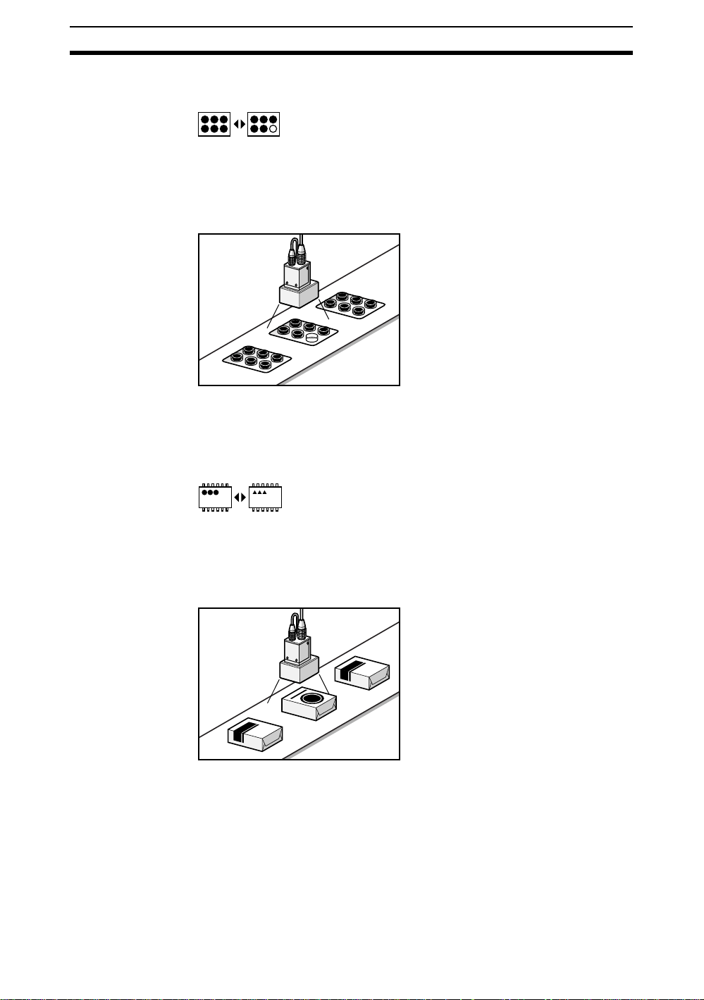
Conformity
SeeAlso Refer to page 48.
Conformity inspections check whether or not the workpiece matches a registered product image.
Inspecting for Package Conformity
• Model checks based on grading marks.
• IC model checks based on numbe r of leads.
• Model checks based on shape.
3
Inspection Types Section 1-2
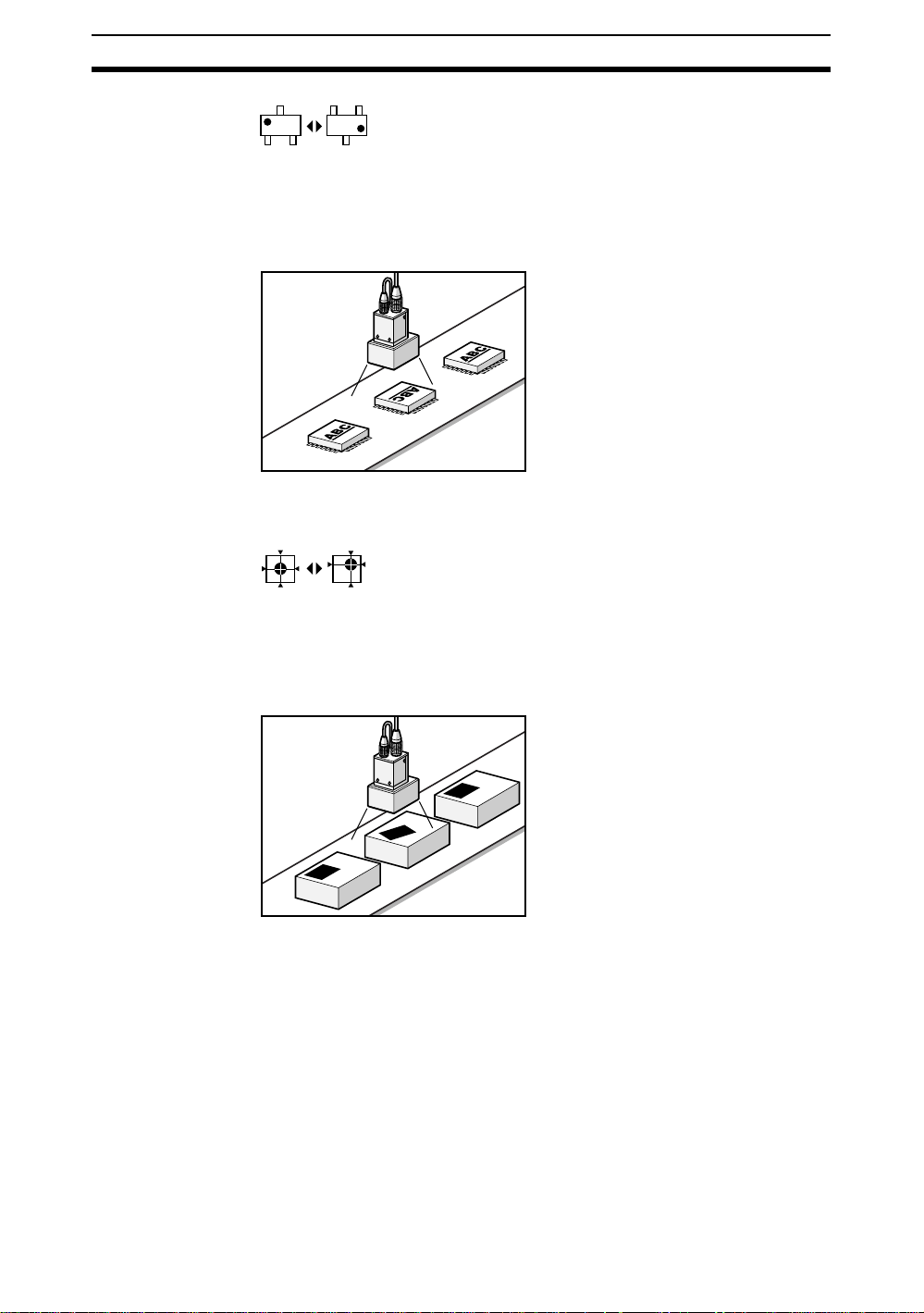
Orientation
Orientation inspections detect the orientation of the workpiece to see if it is
facing correctly.
SeeAlso Refer to page 50.
Checking Label Orientation
• Checks for IC orientation and front/back positioning.
Position
Positi on ins pections find the position of a sp ec ifi ed m ark, hol e , o r othe r feature
and determine whether or not it is within the correct range.
SeeAlso Refer to page 52.
Inspecting for Label Displacement
• Checks for printing displacement.
• Checks for registration marks on liquid crystal.
• Position checks for PCBs.
• Position checks for screw holes.
4
Inspection Types Section 1-2
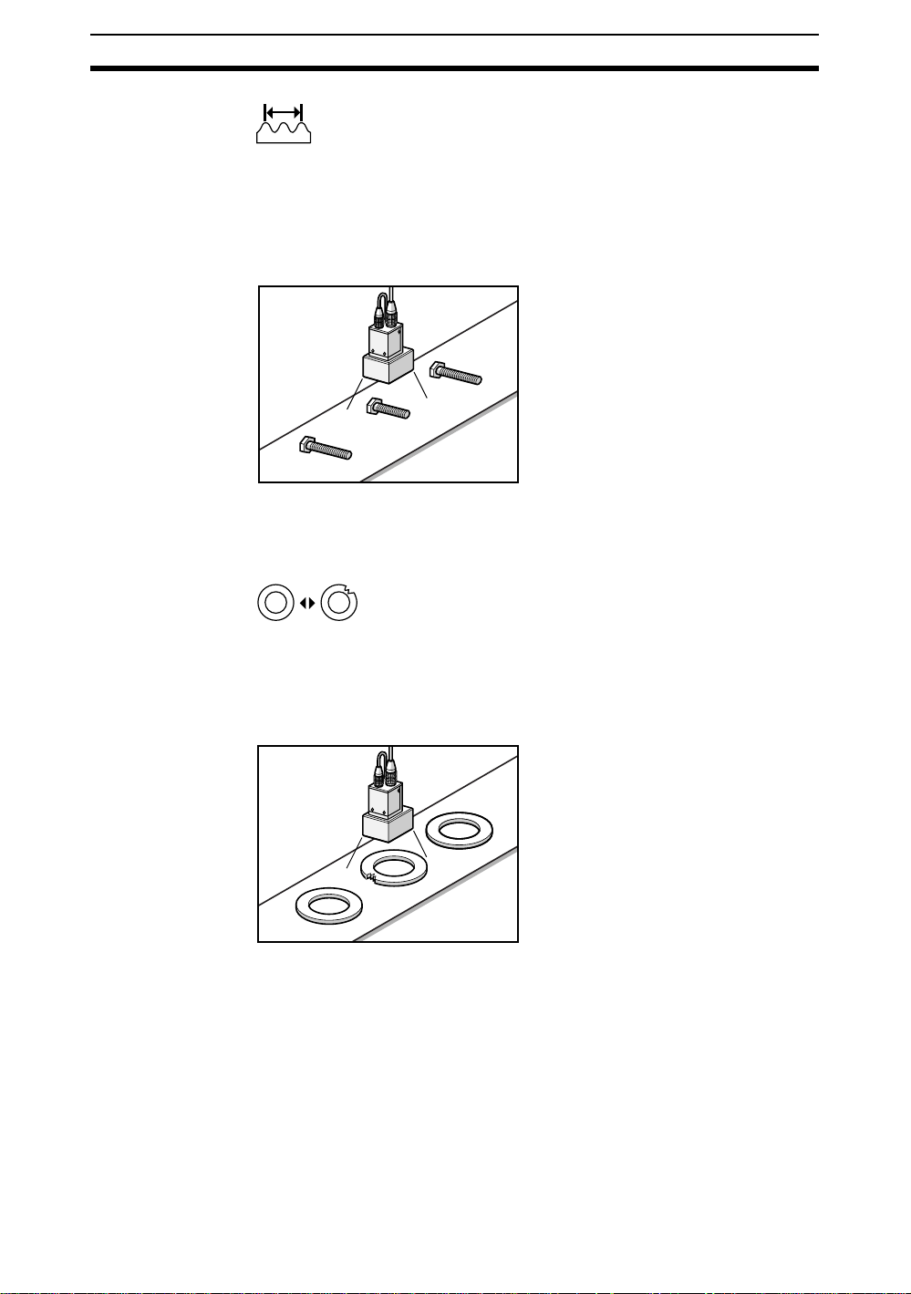
Dimensions
Dimension inspections check the relationship between two specified points
and determine whether or not th e dista nce betw een t he two p oints is withi n the
correct range.
SeeAlso Refer to page 57.
Checking Bolt Length
• Dimension checks for molded products, such as connectors.
• Inspections for pin pitch of capacitors.
Chips and Burs
Chip and bur inspections check for chips and burrs on the profile and circumference of workpieces.
SeeAlso Refer to page 62.
Inspecting for Chips and Burrs on O Rings
• Inspections for chips and burs on plastic molded parts.
5
Inspection Types Section 1-2
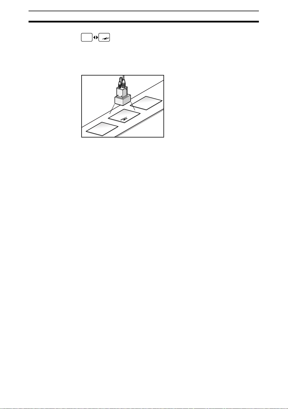
Surfaces
Surface inspections check for defects and impurities within a specified range.
SeeAlso Refer to page 63.
Checking for Marks on Sheets
• Checks for pin holes
• Checks for bubbles on liquid crystal panels.
• Checks for cracks in cast items.
• Checks for impurities in liquids.
6
Advantages of Conversational Menus Section 1-3
1-3 Adv antages of Conversational Menus
Operating guidance is given on the monitor screen and settings can be made
easily by entering information as requested - just as though you are having a
conversation with the F160. Try the Conversational Menus if using a Visual
Sensor for the first time or if you want to set the inspection conditions simply.
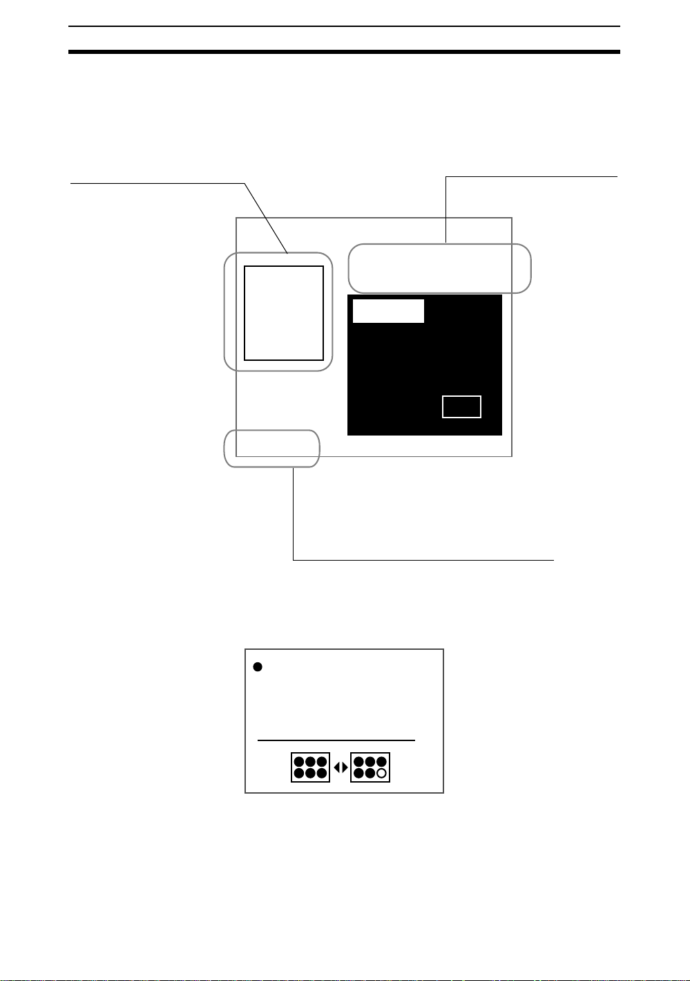
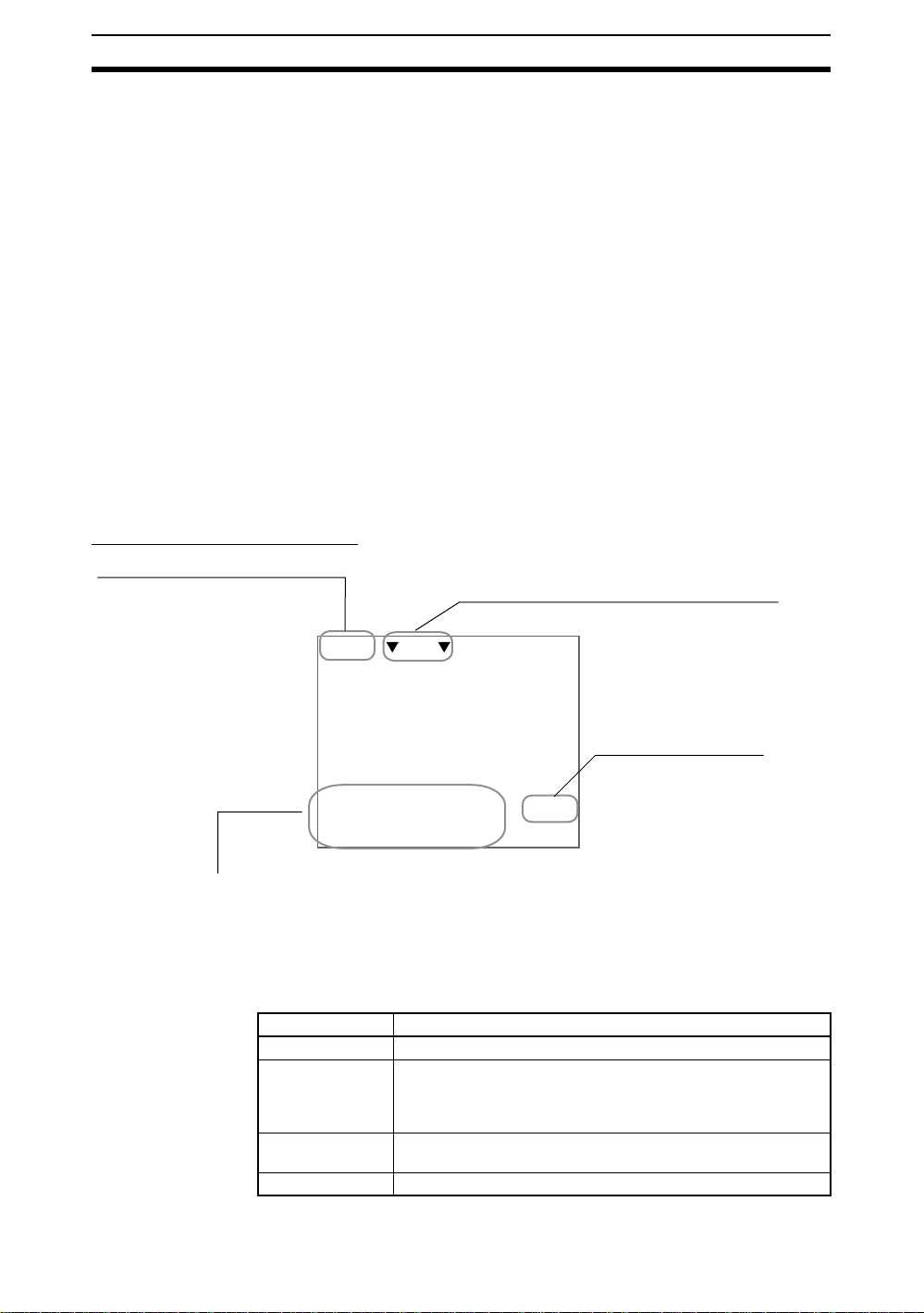
Displays settings sequence
You can grasp what stage you
are at as you proceed.
0.Scn 0 =SET= Region
Start
Ref image
>>Region
Position
End
S+ENT:Help S+←→:Switch display
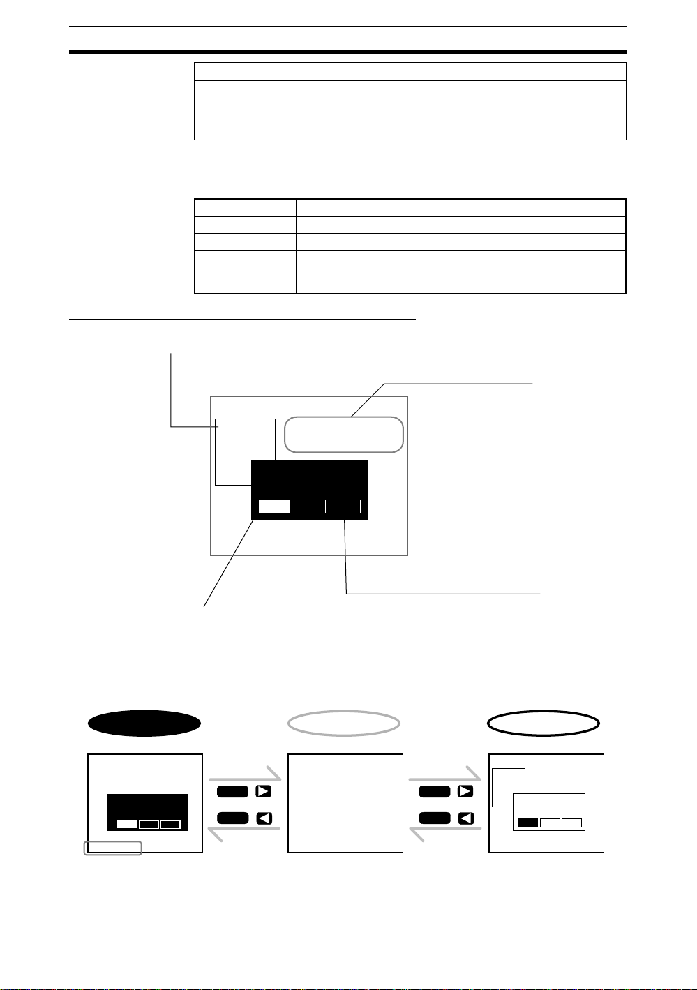
Guides operation
The F160 tells your what the
next procedure is.
Select the type of
inspection.
(Up to 32 regions)
Presence
Orient'n
Dimens'n
Surface
Conform
Position
Chip/Bur
Back
Go to the Help Screen if you are unsure
The F160 has comprehensive Help Screens that give greater
understanding of and hints for settings operations.
Help Screen Example
Presence Inspection
Determines if a component, mark,
hole, etc. is at a set position
on the workpiece.
7
Useful Features Section 1-4
1-4 Useful Features
The F160 provides the following features to enable more accurate and faster
inspections. Refer to the reference pages for details and operating procedures.
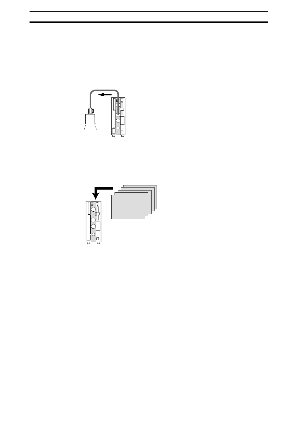
Adjust Lighting Areas and Brightness from the F160
This function is supported only when Intelligent Lighting is connected.
SeeAlso Refer to page 25.
Save Up to 35 NG Images
Past NG resul ts can be che c k ed on the sc reen. Onc e the po wer is turned OFF,
however, the saved images will be cleared. The saved images can be backed
up to a computer.
SeeAlso Refer to page 112.
NG
Change Measurement Setups Smoothly
If the scene function is used, 32 sets of inspection condi tion s ca n be s et. If the
scene group function is used, the setting capacity can be expanded up to
1,024 scenes. The measurement setup can be changed easily for different
types of meas urement objects simply by changing the scene.
SeeAlso Refer to page 71.
Input Measurement Triggers and Output Judgement Results via a Parallel Interface
SeeAlso Refer to the Communications Re ference Manual .
Back Up Settings on a Computer or Memory Card
SeeAlso Refer to page 78.
Manipulate F160 Menus from a Computer
SeeAlso Refer to the Communications Re ference Manual .
8

Operational Flow Section 1-5
1-5 Operational Flow
Preparations
Turn ON the power supply.
The inspection object will appear on the monitor.
SeeAlso Refer to page 12 for information on starting the F160 and displaying images.
Set Detection Conditions
CHECK To learn about the basic operational flow from setting inspection conditions to
1,2,3... 1. Enter Set Mode. (Refer to Starting Conversational Menus on page21.)
SeeAlso Refer to page 48 for information on conformity inspections.
measurement, refer to page 21.
2. Register the reference image. (Refer to Registering Reference Images on
page 22.)
3. Set the detection conditions for presence inspection. (Refer to Selecting
and Setting Inspection Types on page 28.)
4. Compensate for workpiece position displacement. (Refer to Inconsistent
Workpiece Positions on page 31.)
5. Select the measurement method that suits the inspection target.
Refer to page 50 for information on orientation inspections.
Refer to page 52 for information on position inspections.
Refer to page57 for information on dimension inspections.
Refer to page62 for information on chip and bur inspections.
Refer to page63 for information on surface inspections.
Confirm Settings and Execute Measurement
1,2,3... 1. Perform tests and make fine adjustments to measurement conditions. (Re-
fer to Entering Monitor Mode and Testing on page 35.)
2. Start measurement. (Refer to Entering Run Mode and Starting Inspectio ns
on page 43.)
Error Messages
When an error message has been displayed on the screen, refer to Troubleshooting on page124.
Troubleshooting
If you think that there may be a malfunction, refer to FAQ on page 126 or refer
to the Setup Manual.
Changing, Adding, and Deleting Settings
Change, add, or delete the inspection position referring to Changing and
Clearing Inspection Conditions on page 66.
Saving Settings
• Save the inspection conditions. (Refer to Saving Settings and Exiting the
F160 on page 44.)
• Back up the image and system scene data. (Refer to Backing Up Data on
page 78.)
9

Operational Flow Section 1-5
Applied Setting Operations
• Set the measurement conditions by model type. (Refer to Changing
Scenes and Scene Groups on page 71.)
• Set the system environment conditions. (Refer to System Settings on
page 101.)
• Initialize the set inspection conditions. (Refer to Initializing Measurement
Conditions: Clearing Scenes on page 75.)
• Set the communications specifications and I/O format for the external
device. (Refer to the Communicati ons Reference Manu al.)
10

SECTION 2
Basic Operations
This section describes the basic operations of the Conversational Menus.
2-1 Starting the F160 and Displaying Images . . . . . . . . . . . . . . . . . . . . . . . . . . . . 12
2-1-1 Starting the Conversational Menus . . . . . . . . . . . . . . . . . . . . . . . . . . 12
2-1-2 Displaying Images and Focussing. . . . . . . . . . . . . . . . . . . . . . . . . . . 13
2-2 Menu Operations. . . . . . . . . . . . . . . . . . . . . . . . . . . . . . . . . . . . . . . . . . . . . . . 14
2-2-1 Screen Displays. . . . . . . . . . . . . . . . . . . . . . . . . . . . . . . . . . . . . . . . . 14
2-2-2 Key Operations for Input Devices. . . . . . . . . . . . . . . . . . . . . . . . . . . 16
2-2-3 Drawing Figures . . . . . . . . . . . . . . . . . . . . . . . . . . . . . . . . . . . . . . . . 18
2-2-4 Inputting Values. . . . . . . . . . . . . . . . . . . . . . . . . . . . . . . . . . . . . . . . . 19
2-2-5 Inputting Characters . . . . . . . . . . . . . . . . . . . . . . . . . . . . . . . . . . . . . 20
2-3 Understanding Setting Operations. . . . . . . . . . . . . . . . . . . . . . . . . . . . . . . . . . 21
2-3-1 STEP 1: Starting Conversational Menus. . . . . . . . . . . . . . . . . . . . . . 21
2-3-2 STEP 2: Registering Reference Images . . . . . . . . . . . . . . . . . . . . . . 22
2-3-3 STEP 3: Selecting and Setting Inspection Types . . . . . . . . . . . . . . . 28
2-3-4 STEP 4: Inconsistent Workpiece Positions . . . . . . . . . . . . . . . . . . . . 31
2-3-5 STEP 5: Entering Monitor Mode and Testing. . . . . . . . . . . . . . . . . . 35
2-3-6 STEP 6: Entering Run Mode and Starting Inspections. . . . . . . . . . . 43
2-4 Saving Settings and Exiting the F160 . . . . . . . . . . . . . . . . . . . . . . . . . . . . . . . 44
11
Starting the F160 and Displaying Images Section 2-1
2-1 Starting the F160 and Displaying Images
This section describes how to start the F160 Conversational Menus and how
to display im age s on the mo ni tor. Refer to the display ed im age whe n adj usting
the Camera position and focus.
2-1-1 Starting the Conversational Menus
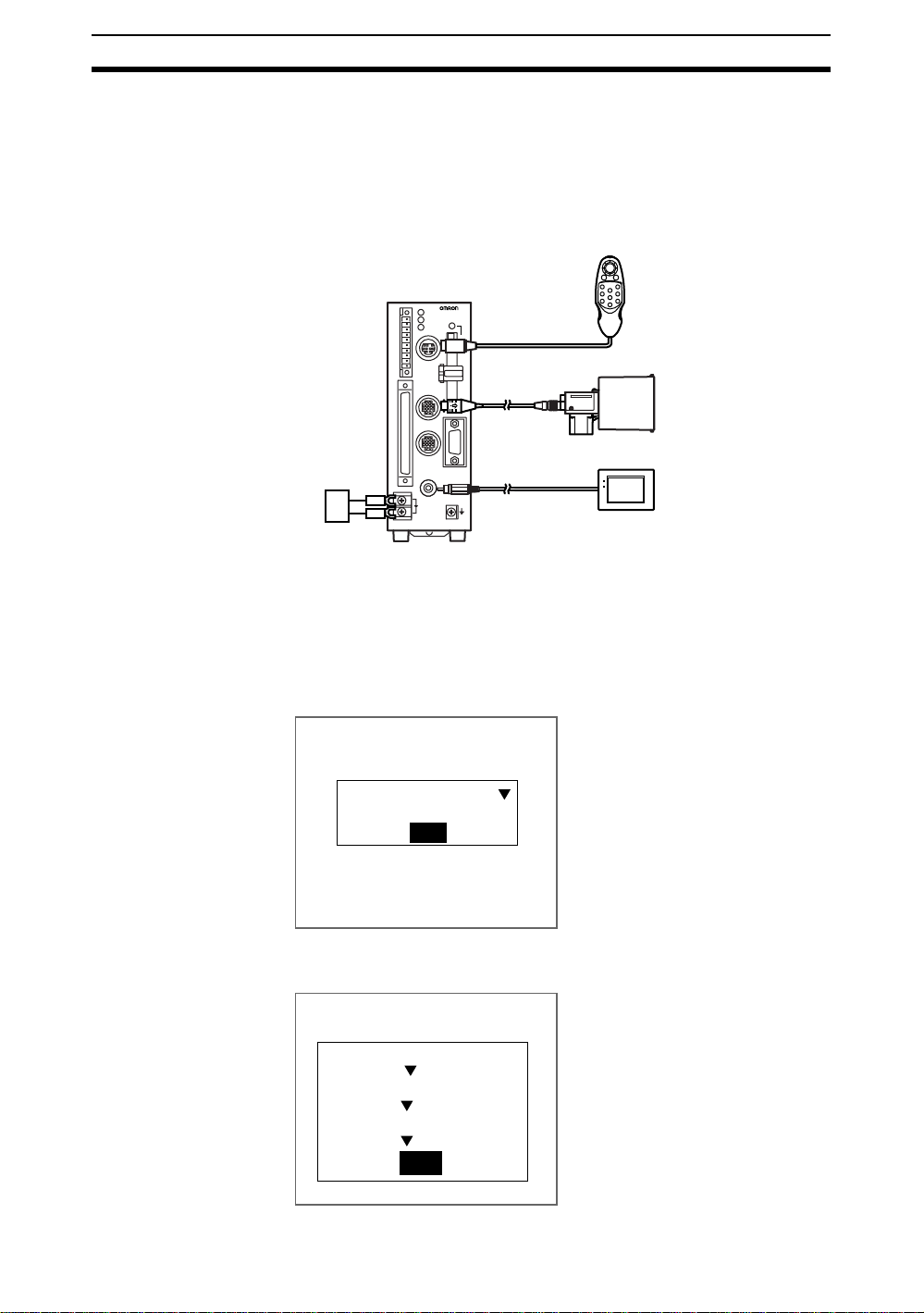
1. Check that the basic F160 components have been connected properly.
F160
VISION MATE
CONTROLLER
F1
F1
F1
SHIFT
ENT
F1
F1
F1
TRIGESC
F1
F1
F1
Console
Camera
Power supply
POWER
SYNC
Monitor
CHECK Before connecting components or wiring p ower supply li nes and g rounding
wires, be sure to refer to the relevant section in the Setup Manual.
SeeAlso Refer to the Setup Manual.
2. Turn ON the power supply to the monitor.
3. Turn ON the power supply on the F160.
The Select Menus Screen will be displayed.
Select Menus
Conversational Menus
End
4. Check that Conversational Menus is selected and press the ENT Key.
After a short pause, the Camera Settings Screen will be displayed.
Camera settings
12
Camera :
F160-S2
Intelligent Lighting 0 :
Out of use
Intelligent Lighting 1 :
Out of use
End
Starting the F160 and Displaying Images Section 2-1
SeeAlso
Refer to page102 for information on the Camera Settings Screen.
5. Select the Camera model to be connected.
6. When using Intelligent Lighting, select the model.
7. Select END.
The Basic Screen for the Conversational Menus will be displayed.
0.Scn 0 MON
press ENT at MON and
then select SET from
---- ---ms
For a new scene,
the menu.
CHECK When the settings have been completed, it is useful to use Startup Mode
when actually operating the F160. Startup Mode is used to set the startup
conditions (display screen) when the F160 is next started. For example,
set the F160 to start in Run Mode. This will allow measurements to be
started immediately and will make day-to-day operations easier. (Refer to
page 118.)
CHECK You can select wheth er or not to display the Select M en us o r Cam era Set-
tings Screens when starting the F160. (Refer to page 118.)
2-1-2 Displaying Images and Focussing
1. Check that the inspection object is displayed on the monitor screen.
0.Scn 0 MON
press ENT at MON and
then select SET from
If it is not displayed, adj ust the p osition of the i nspectio n objec t so that it
appears in the center of the monitor screen.
Adjusting the position of the inspection object.
---- ---ms
For a new scene,
the menu.
2. Focus the Camera.
13
Menu Operations Section 2-2
Cameras with a Light Source (Including Intelligent Lighting)
Lenses hav e a fix ed f ocal po int . Adjust the Camera positio n based on the posi tioning distances in the Setup Manual to focus the Camera.
CHECK The light level for Intelligent Lighting can be adjusted from the F160. The level
can be changed from the screen where the reference image is registered in
Set Mode. (Refer to page 25.)
Using Cameras without Lighting
Turn the focus ring to focus the Camera.
CHECK Camera Shutter Speed
Change the shutter speed if the object is moving quickly, causing the image to
be blurred. The shutter speed can be changed from the screen where the reference image is registered in Set Mode. (Refer to page 24.)
2-2 Menu Operations
The F160 is operated by selecting functions displ ayed on the screen. Familia rize yourself with each function before operating the F160.
2-2-1 Screen Displays
Basic Screen Configuration
The scene number is displayed.
There are 32 scenes. Setting
different measurement conditions
for each scene allows easy
switching between different
setups.
0.Scn 0 MON ---- ---ms
Mode (See note 1.)
The current operating mode is displayed.
The type of image being
displayed is shown. (See note 2.)
S+ENT:Help S+→:Adjust
S+ESC:Set disp
STEP/TRG:Msr S+↑ ↓:Mem img
The Console Keys that can be used on the screen currently displayed and the roles of those keys is displayed.
S indicates the SHIFT Key.
S + ENT indicates that the ENT Key should be pressed while holding down the SHIFT Key.
(Refer to page 16.)
Freeze
Note 1: Modes
Display Meaning
SET Sets the inspection conditions.
MON (Monitor) Checks whether inspection is being performed correctly under
RUN Performs inspection. The measurement results are output to an
SYS (System) Sets system conditions for the F160.
the set inspection conditions. The measurement results are displayed on the monitor only. The results cannot be output to external devices.
external device via a parallel interface.
14
Menu Operations Section 2-2
Display Meaning
TOOL Has data backup and Memory Card menus. Saves settings and
images to a computer or Memory Card as backup.
SAVE Saves data to flash memory. If new settings have been made, be
sure to save the data before quitting.
Note 2: Display Images
SeeAlso Refer to page 104.
Display Meaning
Through The latest image taken by the Camera is displayed directly.
Freeze A still of the image taken by the Camera is displayed.
... Memory@@ The previously saved measurement images are displayed. Up to
36 screens can be saved by the F160 and they are saved in
order from 0 to 35.
Screen Configuration for Conversational Menus
The settings sequence for Conversational Menus is displayed.
>> indicates the current setting step.
Additional information is displayed
for this step or question.
0.Scn 0 =SET= Ref image
Start
>>
Ref image
Region
Position
End
One image must be
saved as a reference
for inspection.
Set the method to
use to store images.
Console STEP Back
S+←→:Display S+ENT:Shutter
Back
Select
or press the ESC Key to return
to the previous screen.
Questions or instructions from the F160 are displayed.
Possible selections are given in boxes.
CHECK The message box is displayed in black to make it easier to read the mes-
sages. When you want to check the whole screen image, use the following
procedure to change the message display conditions.
Black background
All blank
Initial status
0.Scn 0 =SET= Ref image
S+←→:Display S+ENT:Shutter
One image must be
saved as a reference
for inspection.
Set the method to
use to store images.
Console STEP Back
SHIFT
SHIFT
+
+
SHIFT
SHIFT
+
+
Use the S + Left and S + Right Keys to switch between message box display types on the current screen.
Clear background
0.Scn 0 =SET= Ref image
Start
>>
Ref image
Region
Position
End
S+←→:Display S+ENT:Shutter
One image must be
saved as a reference
for inspection.
Set the method to
use to store images.
Console STEP Back
15
Menu Operations Section 2-2
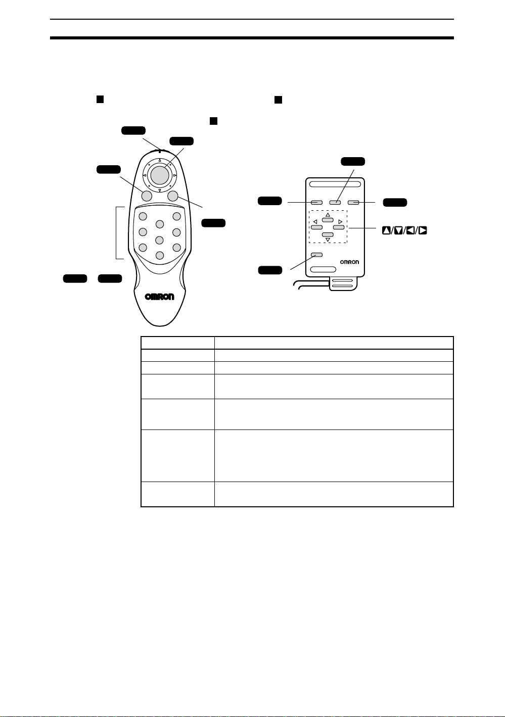
2-2-2 K ey Operations for Input Devices
The menu opera tion s a re pe rformed from the input device, called t he C on so le.
The basic operations of the Console Keys are shown in the following diagram.
F160-KP Console
SHIFT Key
SHIFT
ESC (Escape) Key
ESC
Function Keys
F1 F9
to
F150-KP Console
ENT (Enter) Key
ENT
SHIFT
ENT
TRIGESC
F1
F4
F7
F3
F2
F5
F8
TRIG (Trigger) Key
F6
F9
ESC (Escape) Key
ESC
TRIG
SHIFT Key
SHIFT
Key Function
ESC: Escape Key Returns the user to the previous menu display or operation.
TRIG: Trigger Key Starts object measurement.
ENT: Enter Key Executes a function or sets a value.
Note: Also works as a Cursor Key for the F160-KP.
SHIFT Key Must be pressed in combination with another key to have any
effect. Specific functions are assigned to SHIFT + another key for
specific screens.
Up, Down, Left
and Right Keys
The Up and Down Keys are used to move the cursor up and
down to set values. The Up Ke y will increase a value b y 1 and the
Down Key will decrease a value by 1. Continue pressing the Up
or Down Key to quickly increase or decrease a value.
The Left and Right Keys are used to move the cursor left or right.
Function Keys F1 to F8: Not used
The display capture function can be set to F9. Refer to page 108.
TRIG (Trigger) Key
TRIG
ESC TRIG
SHIFT
F150-KP
CONSOLE
ENT (Enter) Key
ENT
ENT
Up, Down, Left
and Right Keys
CHECK Menu operations can be performed from a personal computer via a serial
SeeAlso For details, refer to the Communications Reference Manual.
Operation Example
16
interface in addition to from the Console Keys.
The following example shows how to use the Console Keys to operation the
menus and how to enter Set Mode.
Menu Operations Section 2-2
1. Press the Right Key once to move the cursor to MON and press the
ENT Key.
0.Scn 0 MON
press ENT at MON and
then select SET from
A list of modes will be displayed.
0.Scn 0 MON
SET
MON
RUN
SYS
TOOL
SAVE
---- ---ms
For a new scene,
the menu.
---- ---ms
2. Use the Up and Down Keys to scroll up and down the list.
To select Set Mode, move the cursor to SET.
3. Press the ENT Key.
The mode at the cursor position, i.e., Set Mode will be selected.
The F160 will enter Set Mode.
0.Scn 0 =SET= Start
>>Start
Ref image
Region
Position
End
Start setting?
Cancel
Start
The initial screen fo r Set Mode f or Con v ersationa l Menus will be displa y ed.
To return to the previous screen, press the ESC Key.
17
Menu Operations Section 2-2
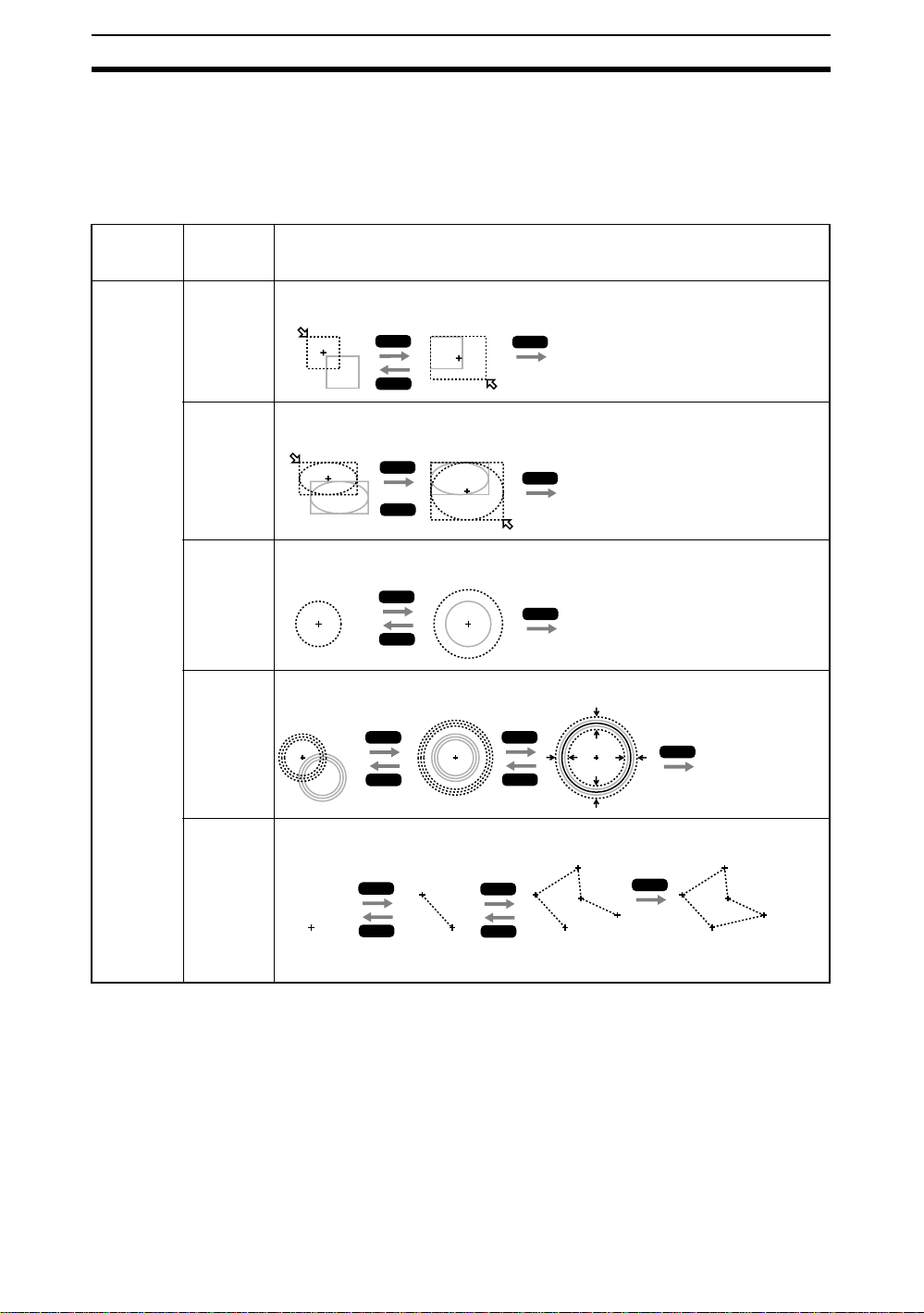
2-2-3 Dra wi ng Figures
This section describes how to draw figures used to specify the region to be
inspected.
Move the cursor with the Up, Down, Left and Right Keys. Use together with
the SHIFT Key to move the cursor quickly. Press the ENT Key at the de sired
positions and press the ESC Key to undo the setting.
Measure-
ment item
Presence
Conformity
Orientation
Surface (for
boxes only)
Figures
that can be
drawn
Box
Ellipse
The whole
region moves.
The whole
region moves.
The lower right
coordinates move.
ENT
ESC
The lower right
coordinates move.
ENT
ESC
Drawing method
ENT
The figure is set.
ENT
The figure is set.
Circle
Circumference
Polygon
The whole
region moves.
The whole
region moves.
Specify the
first point.
ENT
ESC
The circumference
changes.
ENT
ESC
Specify the
second point.
ENT
ESC
The circumference
changes.
ENT
ENT
ESC
Specify the third
and other points.
ENT
ESC
(Up to 10 points can
be specified.)
The figure is set.
The width changes.
ENT
ENT
Press the
ENT Key
twice.
The figure is set.
The figure is set.
18
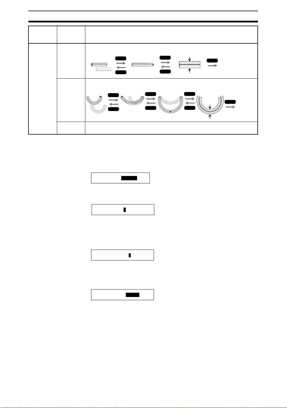
Menu Operations Section 2-2
Measure-
ment item
Figures
that can be
drawn
Chips and
burs
Line
Arc
The whole
region moves.
The whole
region moves.
Circumfer-
Specify the center, diameter, and thickness. Refer to Circumference above.
ence
2-2-4 Inputting Values
This section explains how to input values when setting measurement conditions or communications specifications.
1. Move the cursor to the item for which a value is to be changed.
Output period : [ 10.0 ] ms
2. Press the ENT Key.
The cursor size will change to a cursor the size of a single digit.
ENT
ESC
ESC
ENT
ESC
The length
changes.
The end
point moves.
Drawing method
ENT
ESC
The mid-point
moves.
ENT
ESC
The width changes.
ENT
The width
changes.
ENT
ESC
The figure is set.
The
ENT
figure
is set.
Output period : [ 00010.0] ms
3. Use the Left and Right Keys to move the cursor.
Move the cursor to the digit to be changed.
4. Use the Up Key to increase the value.
Use the Down Key to decrease the value.
Output period : [00030.0] ms
Repeat steps 3 and 4 to change other values.
5. Press the ENT Key.
The values will be set.
Output period : [ 30.0 ]ms
19

Menu Operations Section 2-2
2-2-5 Inputting Characters
This section explains how to input characters. The software keyboard shown
below is displayed on the screen where characters are input.
ABCDEFGHI J K MN
OPQRSTUVWXYZ
abcdefgh i j klmn
opqrs tuvwxyz
0123456789. #$
SPC
%
DEL
()^
BSBSINS
`
←←→
L
!
-
END
1. Move the cursor to the character to be input.
cursor Cursor
[
ABCDEFGHI J K MN
OPQRSTUVWXYZ
abcdefgh i jklmn
opqrs tuvwxyz
0123456789. %
#$
SPC DEL BS INS
2. Press the ENT Key.
The character is set and the I cursor moves one space to the right.
[L
These characters can be input.
Inserts a space.
SPC
Deletes 1character to the right of the I cursor.
DEL
Deletes 1character to the left of the I cursor.
Switches between insert (default)/overwrite.
INS
Moves the I cursor to the left.
→
Moves the I cursor to the right.
Ends character input.
END
]
L
()^
`
←→
]
!
END
20
ABCDEFGHI J K MN
OPQRSTUVWXYZ
L
3. Repeat these steps to input more characters.
4. Once all required characters have been input, move the cursor to END.
()^
%
DEL BS
]
L
!
`
←→
-
END
Ins.
[LABEL
ABCDEFGHI J K MN
OPQRSTUVWXYZ
abcdefgh i jklmn
opqrs tuvwxyz
0123456789. #$
SPC INS
ENT:Select
5. Press the ENT Key.
The characters will be set.

Understanding Setting Operations Section 2-3
2-3 Understanding Setting Operations
This section uses a simple example to explain the procedures for using Conversational Menus, from setting inspection conditions through to starting
inspection. The example used is a presence inspection. The operating guides
displayed on the screen can be used just like a conversation to help perform
procedures.
2-3-1 STEP 1: Starting Conversational Menus
1. The screen shown below will be displayed when the Conversational
Menus are started for the first time.
0.Scn 0 MON
press ENT at MON and
then select SET from
---- ---ms
For a new scene,
the menu.
S+↑ ↓:Mem img
Freeze
2. Move the cursor to MON and press the ENT Key.
A list of modes will be displayed.
0.Scn 0 MON
SET
SET
MON
RUN
SYS
TOOL
SAVE
---- ---ms
3. Use the Up and Down Keys to move the cursor and select SET.
The F160 will enter Set Mode.
Start setting?
Cancel
Start
4. Select Start to start making the settings.
Follow the instructions given by the operation guide displayed on the
screen for the rest of the procedure.
21

Understanding Setting Operations Section 2-3
2-3-2 STEP 2: Registering Reference Images
Copy Sample A found at the end of this manual. Register the Sample A image
on the F160. This image will be used as a reference image for setting inspection conditions .
Console
2
Take image and
check it.
1
Select image
registration methods.
3
Record up to 36 images
STEP signal
+
SHIFT
SHIFT
ENT
+
ESC
CHECK Registered reference images are lost when the power is turned OFF or the
image save function is used. For possible future amendments to inspection
conditions, it is recommended that the reference images are backed up to a
computer or Memory Card. Up to 36 reference images can be reg istere d when
a Console is being used. When a reference image is not backed up, the workpiece must be displayed in the same position and size as the previous inspection to recreate the reference image. (Refer to page 78.)
2-3-2-1 Selecting Image Registration Methods
The Console or the parallel interface STEP signal can be used to register
images.
on STEP signal.
Changes the camera
shutter speed.
Changes the brightness
of Intelligent Lighting.
STEP 3
Select one
reference image
Refer to page 24.
Intelligent Lighting can be
adjusted when Intelligent Lighting
has been specified in the system
camera settings.
Refer to page 25.
22
HELP Console
Once the image is confirmed on the scree n, Cons ol e Keys are pressed to register the i m age.
HELP STEP Signal
A sync signal is input to the STEP signal in the parallel interface to register
images. Up to 36 images can be registered, i.e., you can register several
workpieces as they travel down the production line and select one appropriate
image as the reference im age.
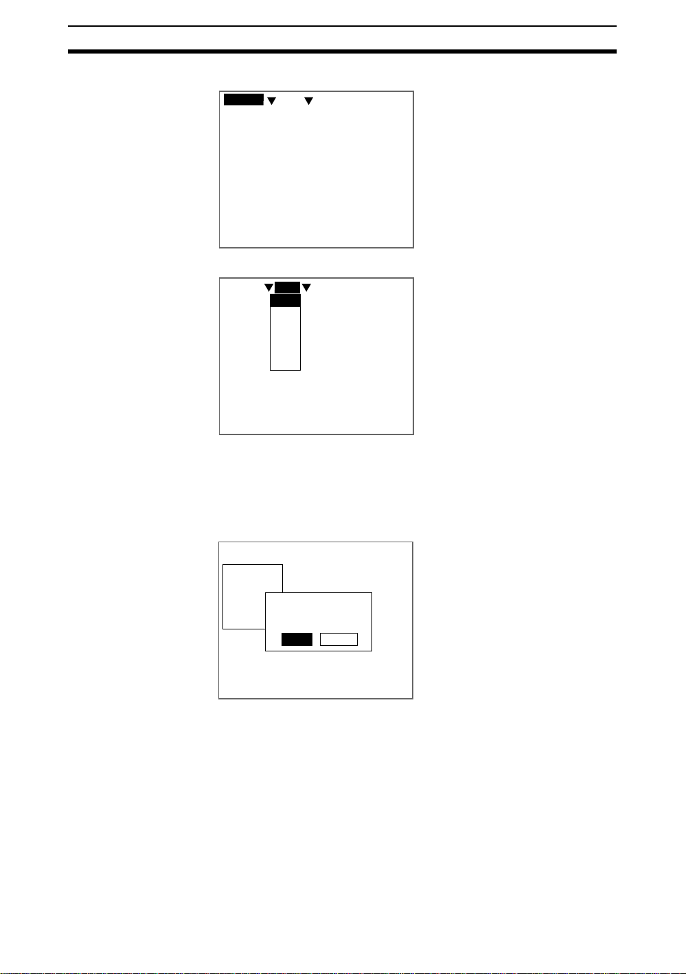
0.Scn 0 =SET= Ref image
Start
>>
Ref image
Region
Position
End
S+ESC:Adjust illumination
S+←→:Display S+ENT:Shutter
Set the method to
use to store images.
Console STEP Back
One image must be
saved as a reference
for inspection.

Understanding Setting Operations Section 2-3
2-3-2-2 When Console Is Selected
1. Set the workpiece in the correct position.
Save image to use for settings.
ENT:Save this image ESC:Back
2. Press the ENT Key on the Console.
A confirmation messa ge will be displayed.
This image will be
the reference image.
Yes
Redo
step
3
3. Select Yes if that image is acceptable as the reference image.
The reference image has now been registered.
2-3-2-3 When STEP Is Selected
1. Set the workpiece and input a sync signal for the STEP signal.
Stored images: 5/36
End
2. When the signal has been input, select End.
Note Up to 36 images can be registered one after the other.
An image selection message will be displayed.
Image to use: 0 [0 to 35]
↑ ↓:Switch ENT:Select ESC:Back
3. Use the Up an d Down Key s t o switch between images and select one im age to be used as the reference for inspection.
4. Once the image has been decided upon, press the ENT Key to select it.
Back
step
0
3
23

Understanding Setting Operations Section 2-3
The reference image registration has now been completed.
Changing Shutter Speed
Change the shutter speed when the object is moving quickly causing the
image to be blurred.
For F150-S1A Cameras
Object movement
Slow
Fast
(Default setting: 1/2000 s)
1. Press the SHIFT + ENT Keys on the screen for selecting the image storage method.
0.Scn 0 =SET= Ref image
Start
>>
Region
Position
End
S+ESC:Adjust illumination
S+←→:Display S+ENT:Shutter
Shutter speed
1/100s
1/500s
1/2000s
1/10000s
Ref image
Set the method to
use to store images.
Console STEP Back
For F160-S2 Cameras
Object movement
Slow
Fast
One image must be
saved as a reference
for inspection.
Shutter speed
1/120s
1/200s
1/500s
1/1000s
1/2000s
1/4000s
1/8000s
1/20000s
(Default setting: 1/2000 s)
24
The Shutter Speed Screen will be displayed.
0.Scn 0 =SET= Ref image
Shutter speed
1/120s
1/200s
1/500s
1/1000s
1/2000s
1/4000s
1/8000s
1/20000s
2. Use the Up and Down Keys to select the shutter speed.
3. Press the ENT Key to set the selection.
The screen in (1.) will return.

Understanding Setting Operations Section 2-3
Adjusting Light Levels for Intelligent Lighting
When using Cameras with Intelligent Lighting, the light level can be adjusted
from the F160.
B. Light volume
Light control(LTC20)
Lighting pattern 1 50000
A. Segment displays
C. Sample lighting pattern number
Segment Display
F150-LTC20
F160-LTC20
As viewed from
this perspective
B
A
E
C
D
Lighting can be adjusted
for 5 areas.
CHECK The measurement points are displayed with thick lines. The brightness
depends on the set light level. Refer to page 26.
Displaying Light Levels
The light level for each segment is displayed as a 5- or 8-digit value, with each
digit representing the light level of one of the segments. The light levels are
displayed from 0 to 7, w i th 0 i ndi cating that the ligh t i s OFF. The higher the setting, the higher the light level.
Segment A level
Segment B level
F150-LTC20
F160-LTC20
3 3 3 3 3
Segment C level
Segment E level
Segment D level
Segment A level
Segment B level
Segment C level
Segment D level
F150-LTC50
F160-LTC50
F150-LTC50
F160-LTC50
E
A
DH
C
G
Lighting can be adjusted
for 8 areas.
3 3 3 3 3 3 3 3
BF
Segment H level
Segment G level
Segment F level
Segment E level
Sample Lighting Patterns
There are 15 sample lighting patterns registered in the F160.
Adjustment Method 1: Sample Lighting Patterns
There are 15 lighting patterns registered in the F160. The lighting can be set
simply by going through the different patterns in order and selecting the one
that gives the clearest image. Use the SHIFT + Up and Down Ke ys t o sw it c h
between sample patterns.
25

Understanding Setting Operations Section 2-3
F150-LTC20, F160-LTC20
■ Not lit
@ Lit (maximum light level)
LIght level Pat-
Pattern
No.
1 471013
50000
Light level Pat-
tern
No.
07070
Light level Pat-
tern
No.
22727
Light level Pat-
tern
No.
00070
Light level
tern
No.
52222
2 581114
3 691215
03333 27272
07777 00707
07000
00700 51111
00007
17777
27777
F150-LTC50, F160-LTC50
Light level Pat-
Pattern
No.
1471013
77777777
2581114
44440000
3691215
77770000
Light level Pat-
tern
No.
00004444
00007777
70707070
Light level Pat-
tern
No.
07070707
70000000
07000000
Light level Pat-
tern
No.
00700000
00070000
00007000
Light level
tern
No.
00000700
00000070
00000007
Adjustment Method 2: Adjusting Light Levels by Segment
The light level for each segment can be set separately to a value between 0
and 7. The setting “0” represents the unlit state, and the higher the setting
value the higher the light level. Light levels can also be set by adjusting the
light levels for the secti ons sep ar ate ly after s ele cti ng a s am ple ligh tin g patt ern.
Use the Left and Right Keys to select the section to be adjusted and use the
Up and Down Keys to adjust the light level.
26
F150-LTC20, F160-LTC20
F150-LTC50, F160-LTC50

Understanding Setting Operations Section 2-3
1. Press the SHIFT + ENT Keys on the screen for selecting the image storage method.
0.Scn 0 =SET= Ref image
Start
>>
Ref image
Region
Position
End
S+ESC:Adjust illumination
S+←→:Display S+ENT:Shutter
use to store images.
Console STEP Back
One image must be
saved as a reference
for inspection.
Set the method to
CHECK If S+ESC: Adjust illumination is not displayed, exit Set Mode and change
the settings under SYS/Camera settings to enable use of Intell igent Light-
ing. (Refer to page 102.)
The Intelligent Lighting Settings Screen will be displayed.
Light control(LTC20)
Lighting pattern: 27272
SFT+←→:Sample
←→:Segment ↑ ↓:Light volume
2. Change the settings.
SHIFT + Left/Right Keys: Switches between sample patterns.
Left/Right Keys: Switches between segments.
Up/Down Keys: Switches between light levels.
3. Press the ENT Key to set the settings.
The screen in (1.) will return.
27

Understanding Setting Operations Section 2-3
2-3-3 STEP 3: Selecting and Setting Inspection Types
Specify the details of the inspection and the region to be inspected. Up to 32
points can be specified for inspection. This section uses presence inspection
as an example to expl ain the settings operation.
Note: Select Presence.
1
Select type
of inspection.
Shape
2
Set inspection
details.
1.2
Specify
points
to inspect.
3
Select
presence
inspection.
2-3-3-1 Selecting Presence Inspection
4
Specify
movement
range.
Size
Brightness
5
Add
inspection
details?
Add
End
6
Return to
screen to
select type
of inspection.
STEP 4
1. If a reference image is set as outlined un der 1-3-2 STEP 2: Registering
Reference Im ages , the insp ection types will b e disp la y ed toge ther with the
operation guide.
2. Use the Up and Down Keys to move the cursor and select Presence.
SHIFT + ENT Keys: Displays an explanation of the inspection type at the
cursor position.
SHIFT + Left/Right K e ys : Switches betw een m essage di spla y types (bl ac k
or transparent backgrounds or blank message boxes.)
0.Scn 0 =SET= Region
Start
Ref image
>>
Region
Position
End
S+ENT:Help S+←→:Switch display
Presence
Orient'n
Dimens'n
Surface
Select the type of
inspection.
(Up to 32 regions)
Conform
Position
Chip/Bur
Back
HELP Presence inspect ion dete cts wh eth er a co mpon ent, mar k, ho le, etc ., i s at
a specified position on the workpiece. Refer to page 3.
3. Press the ENT Key to set the setting.
28

Understanding Setting Operations Section 2-3
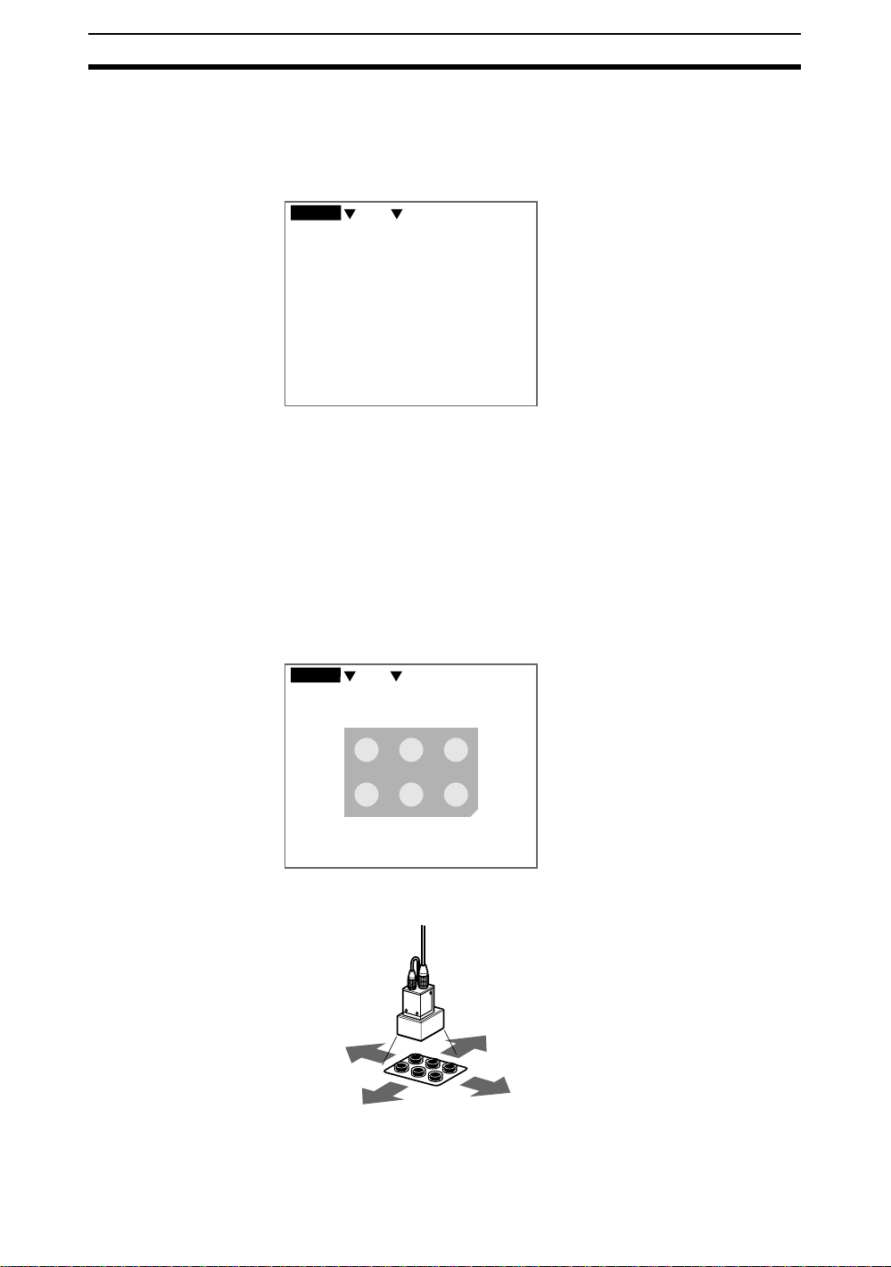
2-3-3-2 Setting Inspection Details
1. Select the shape appropriate for the region to be inspected.
0.Scn 0 =SET= Region
0.Presence
Box
Ellipse
Circle
Circum
Polygon
Enclose the area to
be inspected.
The shape will be displayed.
2. Enclose the region to be in spected.
SeeAlso Refer to page18 Drawing Figures.
Example
Enclose with a circle.
The screen fo r selec tin g ho w to dete rmine the pre senc e of the part will be
displayed.
How do you want to determine
the presence of this part?
Brghtnss BackShape
Size
3. Select the desired method.
29

Understanding Setting Operations Section 2-3
Methods for Determining Presence
Method Details Example
Shape Judges based on
Size Judges based on
Brightness
differences in
shape. Objects
with the same
shape but different orientation will
give an NG result.
differences in size.
Objects with the
same size but different shape will
still give an OK
result.
Judges based on
differences in
brightness.
The following explanation applies if Shapewas selected.
0.Scn 0 =SET= Region
0.Presence
Set the movement range.
Reference
Reference
Reference
220, 341
OKBNG
A
A
OK NG
OK NG
NG
A
NG
NG
↑ ↓←→: Move ENT:Set ESC: Back
4. Specify the object movement range.
If the region to be measured is always in the same position, use the initial
box displayed in dotted lines and use the ENT Key to select the upper-left
and lower-right corners.
If the region to be inspected may be displaced, draw a rectangle large
enough to allow for the range of movement. Use the Up/Down and Left/
Right Keys to move the cursor and use the ENT Key to select the range.
Example
Draw a tall rectangle.
Make sure that surrounding circles are not inside
the rectangle, otherwise they will be included
in the inspection.
30

Understanding Setting Operations Section 2-3
A final message will be displayed.
Add to inspection?
End
Add
STEP 4
5. If nothing more is to be added to the inspection, select End.
CHECK To correct or delete settings , firs t end the s etting and then g o bac k into Se t
Mode and make the changes. (Refer to page 66.)
Select Add to combine other inspections.
0.Scn 0 =SET= Region
Start
Ref image
>>
Region
Position
End
S+ENT:Help S+←→:Switch display
Presence
Orient'n
Dimens'n
Surface
Select the type of
inspection.
(Up to 32 regions)
Conform
Position
Chip/Bur
Back
The screen for selecting the type of inspection will return. Follow the procedure outlined above to set the next inspection conditions.
The settings for the inspection region have now been completed.
2-3-4 STEP 4: Inconsistent Workpiece Positions
Measurement results will not be accurate if the position of the workpiece varies horizontally or vertically. Perform position compensation to enable accurate inspections.
1
Position
compensation?
Yes
No
Check
automatically
selected areas.
Yes
Compensate
2
Correct areas
for position
displacement.
3
Specify
angle range.
4
Finish
settings.
31

Understanding Setting Operations Section 2-3
2-3-4-1 Deciding Whether to Perform Position Displacement Compensation
1. If inspecti on condition s are set in STEP 3, a mes sage f or selecting po sition
compensation will be displayed along with the operation guide.
0.Scn 0 =SET= Position
Start
Ref image
Region
>>Position
Compensate position?
End
S+←→:Switch display
Yes No Back
Position compensa-
tion required to
move workpiece.
2. Check on the Monitor and select Yes if position compensation is re qui red .
If position compensation is not required, select No and go to 2-3-4-4 Fin-
ishing Settings.
Position compensation not
required if the workpiece is
always in the same position.
Position compensation required
if the position of the workpiece varies.
If Yes is sel ected , the F160 a utoma ticall y de termines th e app ropriate posi tion compensation area s .
This part used for compensation.
32
ENT:OK S+ESC:Change ESC:Back
3. If the aut omatic ally selec ted reg ions are acc eptab le , p ress th e ENT Key to
confirm the setting and go to 2-3-4-3 Objects at an Angle.
If the automatically selected regions include marks that are not on every
workpiece or inconsistent shapes, press the SHIFT + ESC Keys to select
Change and go to 2-3-4-2 Changing Position Displacement Compensa-
tion Regions.

Understanding Setting Operations Section 2-3
2-3-4-2 Changing Position Displacement Compensation Regions
1. Enclose with a rectangle two places to use for position compensation.
0.Scn 0 =SET= Position
Enclose mark, hole,
corner, etc., that will be on
every workpiece (2 positions)
↑ ↓←→: Move ENT:Set ESC: Back
Up/Down and Left/Right Keys: Move the arrow cursor.
SHIFT + Up/Down and Left/Right Keys: Move the arrow cursor quickly.
ENT Key: Sets the position.
The screen for setting the movement range will be displayed.
0.Scn 0 =SET= Position
Set movement range
for this part.
(2nd position)
360,360
424,424
↑ ↓←→: Move ENT:Set ESC: Back
2. Specify each movement range.
The F160 will find the part in this mov ement rang e that most res embles the
registered mark and finds the workpiece based on that position.
Go to 2-3-4-3 Ob jects at an Angle.
2-3-4-3 Objects at an Angle
1. Check on the Monitor and select Yes for objects that require angle compensation.
0.Scn 0 =SET= Position
S+←→:Switch display
Is target at an angle?
No
BackYes
33

Understanding Setting Operations Section 2-3
If angle compensation is not required, select No and go to 2-3-4-4 Finishing Settings.
Compensation is not required
if the object is not at an angle.
The screen for selecting the angle range will be displayed.
0.Scn 0 =SET= Position
Appoint the angle range of
the target's leaning.
Angle : ±5°
A rotation range must be
set for objects at an angle.
2. Select the angle range for the object.
Angle range selections
±5°
15°
±
±
30°
45°
±
90°
±
360°
The larger the an gle r an ge, the longer th e t ime required for m ea su rem ent .
3. Select OK.
Go to 2-3-4-4 Finishing Settings.
2-3-4-4 Finishing Settings
1. A message prompting a switch to Monitor Mode will be displayed. Select
Yes.
0.Scn 0 =SET= End
Start
Ref image
Region
Position
>>
End
OK
Settings finished.
Switching to Monitor
Back
Mode.
BackYes
34
• Save before turning OFF power
• Change to Run Mode to
output results.
STEP 5
You will enter Monitor Mode. P erform a test to see if corre ct inspecti ons will
occur.

Understanding Setting Operations Section 2-3
CHECK
Results are n ot output via the p arallel interface in Mo nitor Mode. Chang e to
Run Mode to output the results.
CHECK Always sa ve the condition settings to flash memory after they a re se t. The set -
tings will be cleared when the power is turned OFF if they are not saved
beforehand. (Refer to page86.)
2-3-5 STEP 5: Entering Monitor Mode and Testing
Perform a test to confirm that inspections will be performed according to the
set conditions.
The measurement results can be referred to when adjusting the precision of
the judgement and the measurement time. The results are not output to the
parallel interface or serial interface and so the test can be performed with the
F160 only.
2
Adjust judgement
precision
By region,
position compensation
1
Perform test
measurement
SHIFT
Judgement
+
3
Adjust
Measurement time
measurement time.
STEP 6
+
SHIFT
SHIFT
ENT
+
ESC
2-3-5-1 Performing Test Measurements
1. Press the TRIG Key on the Console or turn ON the STEP signal.
One measurement will be executed.
Help
Display
settings
Use the help function if the
inspection is not correct.
The type of screen display
(freeze or through) can be changed.
35

Understanding Setting Operations Section 2-3
2. If adjustments are required, press the SHIFT + Right Keys to move to the
Adjustment Screen.
The judgement result and
measurement time will be displayed.
63ms
0.Scn 0 MON
NG
Help Messages
OK
OK OK
1-OK
S+ENT:Help S+→:Adjust
S+ESC:Set dip
STEP/TRG:Msr S+↑ ↓:Mem img
A graphic frame and
the inspection result
will appear in each
inspection position.
(For freeze display only)
OK
OK
NG
2-OK
Freeze
The areas to be used for
position compensation
will appear in dotted boxes.
SHIFT + TRIG Keys: Re-execute measurement for the displayed image
(for freeze and stored images only.)
SHIFT + ENT Keys: Display help messages.
SHIFT + ESC Keys: Display screen setting menus.
SHIFT + Up/Down Keys: Display stored images.
Help messages provide countermeasures for possible problems.
Problem Countermeasure Ref. page
Image moves or is out
of focus.
Image too dark or too
light.
OK and NG judgments
inaccurate.
Measurement time too
long.
No graphic frame
appears in the are to
be inspected.
Increase shutter speed or adjust the focus. page 24
Adjust lighting.
Adjust the lens aperture if using normal CCTV
lens.
Adjust the precision of the judgement. page 37
Adjust the measurement time. However, the
inspection accuracy decreases the shorter the
measurement time. Always perform a test and
check the inspection results after adjusting the
measurement time.
The workpiece position may be inconsistent.
Change the settings to allow position compensation.
page 25
page 42
page 32
36

Understanding Setting Operations Section 2-3
Display Settings
Change the image display method as required.
Display settings
Display image : Freeze
End
HELP Freeze
A still of the image taken by the Camera is displayed. Select Freeze when
measuring moving obj ec ts .
HELP Through
The latest image taken by the Camera is displayed directly. It is useful to use
through display when adjusting workpiece positions. However, through display
is set when meas urement is performed, the g raphic frames an d th e j udg em en t
results for each inspection point will not be displayed.
2-3-5-2 Adjusting Judgement Precision
Adjust judgment precision when the OK and NG results are incorrect.
1. Press the SHIFT + Right Keys in Monitor Mode.
0.Scn 0 MON
OK
1-OK
S+ENT:Help S+→:Adjust
S+ESC:Set dip
STEP/TRG:Msr S+↑ ↓:Mem img
The screen for selecting the type of adjustment will be displayed.
OK 63ms
2-OK
Freeze
What do you want to change?
Judgement method
Time
2. Select Judgement method.
37

Understanding Setting Operations Section 2-3
The screen for selecting the target region will be displayed.
0.Scn 0 MON
0.Presence(Shape )
OK
NG 63ms
Select a region
to adjust.
S+ESC:Adjust compensation
STEP/TRG:Msr
↑ ↓:Region ENT:Select ESC:Back
Freeze
3. Use the Up/Down Keys to switch to the target adjustment region.
4. Press the ENT Key to confirm the selection.
A detailed screen for the sel ected region will be displayed.
Example: When "0. Presence (Shape)" has been selected.
Judgement levelMeasurement result
0.Scn 0 MON
0.Presence(Shape )
NG
Shape
STEP/TRG:Msr
ENT:Adjust parameter ESC:Back
NG 63ms
9
PreciseTolerant
Freeze
5. Press the TRIG Key. Measure a sample and look at the relationship between the measurement result and the judgement level.
6. Press the ENT Key.
The Parameter Adjustment Screen will be displayed.
0.Scn 0 MON
0.Presence(Shape )
63ms
38
Shape
End
S+ENT:Check region
↑ ↓:Move ←→:Change ESC:Back
Note: Measurement cannot be executed in this screen.
9
PreciseTolerant
Freeze
7. Use the Up/Down Keys to select the parameter and use the Left/Right
Keys to adjust the level.
CHECK If the SHIFT + ENT Keys are pressed, the F160 will diagnose the inspec-
tion and display advice.
8. Use the Down Key to select End and press the ENT Key.
The settings will be registered and the screen in (5.) will return.

Understanding Setting Operations Section 2-3
Adjustable Parameters
Inspection method Adjustable parameters
Presence
Conformity
Orientation
Shape
(with selfdiagnostic
function)
Size
Brightness
Shape
Size
jdg
Binlvl
Bright
9
PreciseTolerant
9
PreciseTolerant
6
WhiteBlack
9
PreciseTolerant
Judgement precision is set to a
level between 1 and 10.
Judgement precision is set to a
level between 1 and 10.
Adjust the black/white level if the
lighting changed during movement.
Adjust towards black if lighting
became dark.
Adjust towards white if lighting
become bright.
Judgement precision is set to a
level between 1 and 10.
No. of
edges (for
conformity
and orientation inspec-
tions)
Position (with reference)
Dimension
(with self-diagnostic
function)
Numbers : 3
Edg
num
Measure : -100.694
Wid
[ -102.000] [-98.000]
X
Measure : 0.293
Wid
[ - 2.000] [ 2.000]
Y
Measure : 100.694
Dist
[ 98.000] [102.000]
Switch pages +
Shape
Shape
[ 3] [ 3]
SHIFT
PreciseTolerant
PreciseTolerant
ESC
Set the number of edges
for an OK judgement.
Set the X and Y coordinates and
distance for an OK judgement.
Make the shape judgement more
tolerant if the inspection position
9
is not found correctly.
Position inspection:
The upper parameter is for the
9
reference point and the lower
parameter is for the inspection
position.
Dimension inspection:
The upper parameter is for the
first point and the lower parameter
is for the second point.
39

Understanding Setting Operations Section 2-3
Inspection method Adjustable parameters
Position (no reference)
(with self-diagnostic
function)
Measure : -100.694
Pos
[ -102.000] [-98.000]
X
Measure : 0.293
Pos
[ - 2.000] [ 2.000]
Y
Set the range for an OK judgement.
Make the shape judgement
more tolerant if the inspection
position is not found correctly.
Judgement precision is set to a
level between 1 and 10.
Judgement precision is set to a
level between 1 and 10.
Chips and burs
Surface
Shape
Defect
Defect
9
PreciseTolerant
5
PreciseTolerant
5
PreciseTolerant
Changing Judgement Precision for Position Displacement Compensation
The judgement precision can be changed if position displacement compensation is set. If the measurement object is not within the field of vision, an NG
judgement is outp ut a t th e position compensat ion stage, thus preventing in co rrect measurements. The judgement position can be changed for both position
compensation regions.
1. Press the SHIFT + ENT Keys in Monitor Mode.
0.Scn 0 MON
OK
1-OK
OK 63ms
2-OK
40
S+ENT:Help S+→:Adjust
S+ESC:Set disp
STEP/TRG:Msr S+↑ ↓:Mem img
Freeze
The screen for selecting the type of adjustment will be displayed.
What do you want to change?
Judgement method
Time
2. Select Judgement method.

Understanding Setting Operations Section 2-3
The screen for selecting the target region will be displayed.
0.Scn 0 MON
0.Presence(Shape )
OK
NG 63ms
Select a region
to adjust.
S+ESC:Adjust compensation
STEP/TRG:Msr
↑ ↓:Region ENT:Select ESC:Back
Freeze
3. Press the SHIFT + ESC Keys to select Adjust compensation.
The position compensation details will be displayed.
Measurement results
0.Scn 0 MON
Scroll
NG
Jdg
1
Jdg
2
Tolerant
STEP/TRG:Msr
ENT:Adjust parameter ESC:Back
Judgement level
NG 63ms
9
PreciseTolerant
9
Precise
Freeze
4. Press the TRIG Key. Measure a sample and look at the relationship between the measurement result and the judgement level.
5. Press the ENT Key.
The Parameter Adjustment Screen will be displayed.
0.Scn 0 MON
Scroll
Jdg
1
Jdg
2
Tolerant
End
S+ENT:Check region
↑ ↓:Move ←→:Change ESC:Back
Note: Measurement cannot be executed on this screen.
63ms
9
PreciseTolerant
9
Precise
Freeze
6. Use the Up/Down Keys to select the parameter and use the Left/Right
Keys to adjust the level.
CHECK If the SHIFT + ENT Keys are pressed, the F160 will diagnose the inspec-
tion and display advice.
7. Use the Down Key to select End and press the ENT Key.
The settings will be registered and the screen in (4.) will return.
41

Understanding Setting Operations Section 2-3
2-3-5-3 Adjusting Measurement Time
The processing speed can be adjusted if the measurement time is too long
and the line speed too slow.
1. Press the SHIFT + Right Keys in Monitor Mode.
0.Scn 0 MON
OK
OK 63ms
1-OK
S+ENT:Help S+→:Adjust
S+ESC:Set disp
STEP/TRG:Msr S+↑ ↓:Mem img
2-OK
Freeze
The screen for selecting the type of adjustment will be displayed.
What do you want to change?
Judgement method
Time
2. Select Time.
The Measurement Time Settings Screen will be displayed.
0.Scn 0 MON
Time
Long
End
63ms
8
Short
3. Use the Left/Right Keys to adjust the time.
Up/Down Keys: Move the cursor between Time and End.
4. Use the Down Key to select End and press the ENT Key.
A confirmation messa ge will be displayed.
42
The judgement results will
change if the measurement
time is changed.
Check the results.
OK
5. Select OK.
The settings will be registered and the screen in (1.) will return.

Understanding Setting Operations Section 2-3
2-3-6 STEP 6: Entering Run Mode and Starting Inspections
This section describes how to enter Run Mode and start inspections. The
measurement results will also be output to the parallel interface.
1
Enter
Run Mode.
2
Start
inspections.
SHIFT
SHIFT
SHIFT
2-3-6-1 Entering Run Mode
1. Move the cursor to OK to change the mode.
0.Scn 0 MON
Judgement
+
Measurement time
+
ENT
+
ESC
OK
OK
OK OK
Help
Display
settings
OK
OK
OK
Adjust judgement
precision
By region,
position compensation
Adjust
measurement time.
Use the help function if
the inspection is not correct.
Refer to page 37.
Refer to page 42.
Refer to page 36.
The type of screen display
(freeze or through) can be changed.
Refer to page 37.
63ms
2. Press the ENT Key.
The mode selections will be displayed.
OK
0.Scn 0 MON
SET
OK
MON
RUN
RUN
SYS
OK OK
TOOL
SAVE
OK
63ms
OK
OK
3. Use the Up/Down Keys to move the cursor and select RUN.
The Run Mode Screen will be displayed.
43

Saving Settings and Exiting the F160 Section 2-4
2-3-6-2 Starting Inspections
1. Press the TRIG Key on the Console or turn ON the STEP signal.
0.Scn 0 RUN
---- ---ms
S+ENT:Help S+→:Adjust
S+ESC:Set disp
STEP/TRG:Msr S+↑ ↓:Mem img
Freeze
SHIFT + TRIG Keys: Re-execute measurement for the displayed image (for freeze and stored images only.)
SHIFT + ENT Keys: Display help messages.
SHIFT + Right Keys: Go to Adjustment Screen.
SHIFT + ESC Keys: Display screen setting menus.
SHIFT + Up/Down Keys: Display stored images.
One measurement will be performed.
63ms
OK
NG
OK
NG
2-OK
Freeze
0.Scn 0 RUN
OK
OK OK
1-OK
S+ENT:Help S+→:Adjust
S+ESC:Set disp
STEP/TRG:Msr S+↑ ↓:Mem img
2-4 Saving Settings and Exiting the F160
Save settings to flash memory before turning the power OFF.
Precaution Flash memory data is loaded each time the F160 is started. Therefore, when
settings have been changed, be sure to save them to flash memory before
turning OFF the power. If the power is turned OFF without saving new settings, all of the setting changes will be lost. Stored images cannot be saved to
flash memory, so all stored images will be cleared when the power is turned
OFF. If you want to keep stored images, backup the images to a personal
computer or Memory Card. Refer to page 78.
1. Display the Basic Screen for Monitor Mode or Run Mode.
0.Scn 0 MON
---- ---ms
2. Move the cursor to MON (or RUN) and press the ENT Key.
44

Saving Settings and Exiting the F160 Section 2-4
The mode selections will be displayed.
0.Scn 0 MON
SET
MON
RUN
SYS
TOOL
SAVE
---- ---ms
3. Select SAVE.
A confirmation messa ge will be displayed.
Setting data will be saved.
Execute Cancel
4. Select Execute.
Precaution Do not turn OFF the power or input a RESET signal while a message is
being displayed in any save or load operation. Data in memory will be destroy ed, and the F16 0 m ay not operate correctly the nex t ti me it i s s ta rted.
Once the setting data has been saved, the screen in (1.) return.
5. Turn OFF the power to exit the F160.
CHECK When Using the Scene Group Function
The scene data set to Scene Group 0 and the system data will be saved
to flash memory. The settings data for Scene Groups 1 to 31 will be overwritten to the Memory Card when this save operation is executed.
45


SECTION 3
Designing Inspections for Specific Applications
The Conversational Menus provide 7 inspection methods. Presence inspec t ion proced ures were explained i n 23 Understanding Setting Oper ations. The specific settings for the other six inspection methods ar e explained in
this section. The selection of the inspection method is STEP 3 in the operational flow. Once the selection has
been made, move to STEP 4.
3-1 Conformity. . . . . . . . . . . . . . . . . . . . . . . . . . . . . . . . . . . . . . . . . . . . . . . . . . . . 48
3-1-1 Selecting Conformity Inspection. . . . . . . . . . . . . . . . . . . . . . . . . . . . 48
3-1-2 Setting Inspection Details . . . . . . . . . . . . . . . . . . . . . . . . . . . . . . . . . 49
3-2 Orientation. . . . . . . . . . . . . . . . . . . . . . . . . . . . . . . . . . . . . . . . . . . . . . . . . . . . 50
3-2-1 Selecting Orientation Inspection. . . . . . . . . . . . . . . . . . . . . . . . . . . . 50
3-2-2 Setting Inspection Details . . . . . . . . . . . . . . . . . . . . . . . . . . . . . . . . . 51
3-3 Position . . . . . . . . . . . . . . . . . . . . . . . . . . . . . . . . . . . . . . . . . . . . . . . . . . . . . . 52
3-3-1 Selecting Position Inspection . . . . . . . . . . . . . . . . . . . . . . . . . . . . . . 52
3-3-2 Setting Inspection Details . . . . . . . . . . . . . . . . . . . . . . . . . . . . . . . . . 53
3-4 Dimension . . . . . . . . . . . . . . . . . . . . . . . . . . . . . . . . . . . . . . . . . . . . . . . . . . . . 57
3-4-1 Selecting Dimension . . . . . . . . . . . . . . . . . . . . . . . . . . . . . . . . . . . . . 58
3-4-2 Setting Inspection Details . . . . . . . . . . . . . . . . . . . . . . . . . . . . . . . . . 58
3-5 Chips and Burs. . . . . . . . . . . . . . . . . . . . . . . . . . . . . . . . . . . . . . . . . . . . . . . . . 62
3-5-1 Selecting Chips and Burs . . . . . . . . . . . . . . . . . . . . . . . . . . . . . . . . . 62
3-5-2 Specifying Inspection Regions . . . . . . . . . . . . . . . . . . . . . . . . . . . . . 62
3-6 Surface. . . . . . . . . . . . . . . . . . . . . . . . . . . . . . . . . . . . . . . . . . . . . . . . . . . . . . . 63
3-6-1 Selecting Surface. . . . . . . . . . . . . . . . . . . . . . . . . . . . . . . . . . . . . . . . 63
3-6-2 Specifying Inspection Regions . . . . . . . . . . . . . . . . . . . . . . . . . . . . . 63
47

Conformity Section 3-1
3-1 Conformity
Conformity in sp ect ion s check whet her or not the workpiece matc hes the registered product.
SeeAlso Refer to page 3 Inspection Types.
The settings operation is shown in the following diagram. Only the outline will
be given here. Follow the instructions given by the operational guide on the
Monitor screen.
1
Selec
Conformity
2
Set inspection
details.
.
1.
Select
type of
inspection.
Shape
Size
Brightness
No. of edges
2.
Specify
points to
inspect.
3.
Specify
movement
range.
4.
Check
number of
edges
inspected.
5.
Add
inspection
details?
Add
End
Return to
screen to
select type
of inspection.
STEP 4
3-1-1 Selecting Conformity Inspection
Select Conform on the screen for selecting inspection types.
48
0.Scn 0 =SET= Region
Start
Ref image
>>
Region
Position
End
S+ENT:Help S+←→:Switch display
Presence
Orient'n
Dimens'n
Surface
Select the type of
inspection.
(Up to 32 regions)
Conform
Position
Chip/Bur
Back

Conformity Section 3-1
3-1-2 Setting Inspection Details
1. Select the method for checking non-conforming items.
0.Scn 0 =SET= Region
0.Conform
Select the method to check for
non-conforming items.
Shape
Lines
S+ENT:Help S+←→:Switch display
2. Follow the instructions provided by the on-screen operational guide to
make the rest of the settings.
Checking Methods
Methods for Judging Conformi ty
Checking
method
Shape Judges based on differences in
shape. Objects with the same
shape but different orientation will
give an NG result.
Details Example
Size
Brightness
Back
Reference
OK NG
NG
Movement Range
If the Inspection Point is Always in the Same Position
Use the initial box displayed in dotted lines and select
the upper-left and lower-right corners.
If the Inspection Point is Inconsistent
Draw a box that encloses the range of positions.
Do not include surrounding patterns or other
marks in the box because they will be included
in the inspection.
Size Judges based on differences in
Brightness Judges based on differences in
Lines (No. of
edges)
size. Objects with the same size
but different shape will still giv e an
OK result.
brightness.
Judges based on the number of
edges.
The only shape that can be drawn is a box.
The edges are detected in the
direction of the long side of the box.
Reference
Reference
Reference
OK
NG
OK NG
NG
OK
NG
NG
NG
Inspection
direction: 2 edges
Inspection
direction: 0 edges
49

Orientation Section 3-2
3-2 Orientation
Orientation inspec tions detect the orientati on of t he workpiec e and to see if the
workpiece is facing the correct direction.
SeeAlso Refer to page 3 Inspection Types.
The settings operation is shown in the following diagram. Only the outline will
be given here. Follow the instructions given by the operational guide on the
Monitor screen.
1
Select
Orientation.
5. 2.
Add
inspection
details.
Add
End
Return to
screen to
select type
of inspection.
STEP
4
2
Set inspection
details.
1.
Select
type of
inspection.
Number of edges
Shape
Size
Brightness
Specify
points to
inspect.
3.
Specify
movement
range.
4.
Check
number of
edges.
3-2-1 Selecting Orientation Inspection
Select Orient’n on the screen for selecting inspection types.
50
0.Scn 0 =SET= Region
Start
Ref image
>>
Region
Position
End
S+ENT:Help S+←→:Switch display
Presence
Orient'n
Dimens'n
Surface
Select the type of
inspection.
(Up to 32 regions)
Conform
Position
Chip/Bur
Back

Orientation Section 3-2
3-2-2 Setting Inspection Details
1. Select the method for checking the orientation of items.
0.Scn 0 =SET= Region
0.Orient'n
Select the method to check the
orientation.
Shape
Lines
S+ENT:Help S+←→:Switch display
2. Follow the instructions provided by the on-screen operational guide to
make the rest of the settings.
Checking Methods
Methods for Judging Conformi ty
Checking
method
Shape Judges based on differences in
shape. Objects with the same
shape but different orientation will
give an NG result.
Details Example
Size
Brightness
Back
Reference
OK NG
NG
Movement Range
If the Inspection Point is Always in the Same Position
Use the initial box displayed in dotted lines and
select the upper-left and lower-right corners.
If the Inspection Point is Inconsistent
Draw a box that encloses the range of positions.
Do not include surrounding patterns or other
marks in the box because they will be included
in the inspection.
Size Judges based on differences in
Brightness Judges based on differences in
Lines (No. of
edges)
size. Objects with the same size
but different shape will still giv e an
OK result.
brightness.
Judges based on the number of
edges.
The only shape that can be drawn is a box.
The edges are detected in the direction
of the long side of the box.
Reference
Reference
Reference
OK
OK NG
OK
Inspection
direction: 2 edges
NG
NG
NG
NG
NG
Inspection
direction: 0 edges
51

Position Section 3-3
3-3 Position
Positi on ins pections find the position of a sp ec ifi ed m ark, hol e , o r othe r feature
and determine whether or not it is within the correct range.
SeeAlso. Refer to page 3 Inspection Types.
The settings operation is shown in the following diagram. Only the outline will
be given here. Follow the instructions given by the operational guide on the
Monitor screen.
1
Select
Position
.
2
Set inspection
details.
1.
Physical units
for OK item
range?
6.
Specify
reference
point?
Yes
No
Yes
2.
Specify
origin
coordinate
system.
7.
Specify
reference
point.
8.9.
Specify
OK
range.
3-3-1 Selecting Position Inspection
Select Position on the screen for selecting inspection types.
0.Scn 0 =SET= Region
Start
Ref image
>>
Region
Position
End
S+ENT:Help S+←→:Switch display
Presence
Orient'n
Dimens'n
Surface
Select the type of
inspection.
(Up to 32 regions)
Conform
Position
Chip/Bur
Back
3.
Specify
direction
coordinate
system.
10.
Add
inspection
details.
4.
Specify
magnification.
Add
End
5.
Specify
points to
inspect.
Return to
screen to
select type
of inspection.
STEP 4
52

Position Section 3-3
3-3-2 Setting Inspection Details
1. Decide whether or not to specify physical units for the OK item range.
0.Scn 0 =SET= Region
0.Position
Do you want to set the
range in physical units?
No
Yes
Back
CHECK This screen will not be displayed if the coord inate system, has alread y
been set in another inspection region.
If Yes is Selected
Set the range for OK items in physical units. Go to step (2.)
o
20 mm
If No is Selected
Set the range for OK items in pixel units. Go to step (5.)
286 pixels
The following explanation of how to align the coordinate scale with the dimensions of the workpiece will use a workpiece on an angle as an example.
0.Scn 0 =SET= Region
Set coordinates
Set the position
of the origin.
100.0
X=109
Y=326
100.0 X
O
Y
↑ ↓←→:Change ENT:Set ESC:Back
-100.0
2. Align the origin of the coordinates (0) with the left corner or other part of
the workpiece that will serve as the origin for the physical units.
Up/Down and Left/Right Keys: Move the origin (0).
SHIFT + Up/Down or Left/Right Keys: Move the origin quickly.
ENT Key: Sets the position.
53

Position Section 3-3
The screen for aligning the coordinate axis will be displayed.
0.Scn 0 =SET= Region
Set coordinates
Set the angle of
coordinate axis.
100.0
O
Y
↑ ↓←→:Change ENT:Set ESC:Back
100.0 X
-100.0
3. If the workpiece is on an angle, use the Down/Right and Up/Left Keys to
specify the angle for the axis.
Down and Right Keys: Rotates the axis in the clockwise direction.
Up and Left Ke y s: Rotate s the ax is in the ant i-c lockwise direction.
SHIFT + Down/Right or Up/Left Keys: Rotates the axis quickly.
ENT Key: Sets the position.
The screen for setting the magnification will be displayed.
0.Scn 0 =SET= Region
Set coordinates
Set the
magnification.
10.0
θ=10.0
Zoom=0.069
Sight=38.881
O
Y
↑ ↓←→:Change ENT:Set ESC:Back
Example: 20 mm Workpiece
Align the origin with the bottom left corner of the
workpiece and enlarge or reduce the scale to match
20.0 on the scale with the bottom right corner of the workpiece.
10.0 X
-100.0
20 mm
4. Use the Down/Right and Up/Left Keys to enlarge and reduce the coordinate scale and align with the physical dimensions of the workpiece.
Up/Left Keys: Enlarge the scale.
Down/Right Keys: Reduce the scale.
SHIFT + Down/Right or Up /Left: Reduces or enlarge s the sc ale quic k-
ly.
ENT Key: Sets the magnification.
54

Position Section 3-3
The screen for specifying the inspection position will be displayed.
0.Scn 0 =SET= Region
0.Position
Set position
to inspect.
S+ESC:Adjust coordinates
↑ ↓←→: Move ENT:Set ESC: Back
5. Use the Up/Down and Left/Right Keys to move the cursor to the position
to be inspected. This specifies the inspection position.
SHIFT + Up/Down or Left/Right Keys: Move the cursor quickly.
SHIFT + ESC Keys: Used to correct the position. Returns to the
screen for aligning the coordinate axis.
ENT: Sets the position.
A screen giving the option to sp ecify a ref er ence posit ion will be disp la yed .
Do you want to specify
the reference position?
No
BackYes
X=359.712
Y=292.826
6. Select Yes to specify a relationship between the inspection point and a
particular point on the workpiece.
Select No if no particular relationship is to be specified.
If Yes is Selected
Any point can be specified as the reference point. The relationship between the two poi nts is f ound when insp ection is perf ormed. Go to st ep (7.)
Reference position
+
+
If No is Selected
The origin will become the reference point. Go to step (9.)
Origin
+
+
55

Position Section 3-3
If Yes was selecte d in step (6. ), the scree n f o r specif ying the ref erenc e position will be displa yed.
Coordinates with the origin as the specified
reference position and the distance from the origin.
0.Scn 0 =SET= Region
0.Position(Ref )
Set reference
position.
S+ESC:Adjust coordinates
↑ ↓←→: Move ENT:Set ESC: Back
7. Use the Up/Down and Left/Right Keys to move the cursor to the refer-
ence position.
SHIFT + Up/Down or Left/Right Keys: Move the cursor quickly.
SHIFT + ESC Keys: Used to correct the position. Returns to the
screen for aligning the coordinate axis.
ENT: Sets the position.
X= 239.881
Y= 157.342
Dist= 286.821
Reference position
Width X
Distance
Width Y
The screen for changing the range for OK items will be displayed.
0.Scn 0 =SET= Region
0.Position(Ref )
Set the range
for OK items.
X : [ 237.000: 241.000]
Y : [ 155.000: 159.000]
Dist : [ 284.000: 288.000]
End
Range for OK items automatically calculated
by the F160 based on the coordinates.
X= 239.881
Y= 157.342
Dist= 286.821
Back
SeeAlso Refer to page19 for details on inputting values.
8. Mov e the cursor to th e val ue to be ch anged and s et the ran ge fo r OK items .
Go to step (10.)
56

Dimension Section 3-4
If No was selected at step (6.), the screen f o r ch ang ing the O K it em ra nge
will be displayed.
0.Scn 0 =SET= Region
0.Position(No ref)
Set the range
for OK items.
X: [ 357.000: 361.000]
Y: [ 290.000: 294.000]
X= 359.712
Y= 292.826
Dist= 283.155
SeeAlso Refer to page19 for details on inputting values.
9. Move the cursor to the value to be changed and specify the range for OK
10. Select End.
11. Select End if there are no more conditions to be added to the inspection.
3-4 Dimension
End
Range for OK items
automatically calculated
by the F160 based on
the coordinates.
Back
Coordinates for inspection
position for which the origin
is the upper left corner of
the screen.
items.
A confirmation messa ge will be displayed.
Add to inspection?
End
Add
STEP 4
Dimension inspections inspect the relationship (distance) between two specified points to see if it is within a range.
SeeAlso Refer to page 3 Inspection Types.
57

Dimension Section 3-4
The settings operation is shown in the following diagram. Only the outline will
be given here. Follow the instructions given by the operational guide on the
Monitor screen.
1
Select
Dimns/n.
2.
Specify
origin
coordinate
system.
2
Set inspection
details.
1.
Physical units
for OK item
range?
Yes
6.
Specify
2nd
position.
3-4-1 Selecting Dimension
Select Dimns’n on the screen for selecting inspection types.
3.
Specify
direction
coordinate
system.
8.7.
Sepcify
OK item
range.
4.
Specify
magnification.
9.
Add
inspection
details.
Add
End
5.
Specify
1st
position.
Return to
screen to
select type
of inspection.
STEP 4
0.Scn 0 =SET= Region
Start
Ref image
>>Region
Position
End
S+ENT:Help S+←→:Switch display
Presence
Orient'n
Dimens'n
Surface
Select the type of
(Up to 32 regions)
Conform
Position
Chip/Bur
Back
3-4-2 Setting Inspection Details
1. Select whether the range for OK items will be set in physical units.
0.Scn 0 =SET= Region
0.Dimens'n
Do you want to set the
range in physical units?
Yes
CHECK This screen will not be displa yed if the coo rdinate system has alre ady been
aligned in another inspection region.
No
inspection.
Back
58

Dimension Section 3-4
If Yes is Selected
Set the range for OK items in physical units. Go to step (2.)
20 mm
If No is Selected
Set the range for OK items in pixel units. Go to step (5.)
230 pixels
The following explanation of how to align the coordinate scale with the dimensions of the workpiece will use a workpiece on an angle as an example.
0.Scn 0 =SET= Region
Set coordinates
Set the position
of the origin.
100.0
X = 155
Y = 326
-100.0
↑ ↓←→:Change ENT:Set ESC:Back
O
Y -100.0
100.0
X
2. Align the origin of the coordinates (O) with the left corner or other part of
the workpiece that will serve as the origin for the physical units.
Up/Down and Left/Right Keys: Move the origin (O).
SHIFT + Up/Down or Left/Right Keys: Move the origin quickly.
ENT Key: Sets the position.
The screen for aligning the coordinate axis will be displayed.
0.Scn 0 =SET= Region
Set coordinates
Set the angle of
coordinate axis.
100.0
-100.0
↑ ↓←→:Change ENT:Set ESC:Back
O
Y
-100.0
100.0
θ=10.0
X
3. If the workpiece is on an angle, use the Down/Right and Up/Left Keys to
specify the angle for the axis.
Down and Right Keys: Rotates the axis in the clockwise direction.
59

Dimension Section 3-4
Up and Left Ke y s: Rotate s the ax is in the ant i-c lockwise direction.
SHIFT + Down/Right or Up/Left Keys: Rotates the axis quickly.
ENT Key: Sets the position.
The screen for setting the magnification will be displayed.
0.Scn 0 =SET= Region
Set coordinates
Set the
magnification.
10.0
Zoom= 0.087
Sight=49.023
-10.0
Example: 20 mm Workpiece
Align the origin with the bottom left corner of the
workpiece and enlarge or reduce the scale to match
20.0 on the scale with the bottom right corner of the workpiece.
O
10.0
Y
↑ ↓←→:Change ENT:Set ESC:Back
-10.0
20 mm
X
4. Use the Down/Right and Up/Left Keys to enlarge and reduce the coordinate scale and align with the physical dimensions of the workpiece.
Up/Left Keys: Enlarge the scale.
Down/Right Keys: Reduce the scale.
SHIFT + Down/Right or Up /Left: Reduces or enlarge s the sc ale quic k-
ly.
ENT Key: Sets the magnification.
The screen for specifying the inspection start position will be displayed.
0.Scn 0 =SET= Region
0.Dimens'n
Specify the 1st
position.
X=182.712
Y=200.426
60
S+ESC:Adjust coordinates
↑ ↓←→: Move ENT:Set ESC: Back
5. Use the Up/Down and Left/Right Keys to move the cursor to the position
to be inspected. This specifies the start position (1st position).
SHIFT + Up/Down or Left/Right Keys: Move the cursor quickly.
SHIFT + ESC Keys: Used to correct the position. Returns to the
screen for aligning the coordinate axis.
ENT: Sets the position.

Dimension Section 3-4
A screen giving the optio n to specify the inspection e nd position wil l be displayed.
Dimensions and distance
0.Scn 0 =SET= Region
0.Dimens'n
Specify the 2nd
position.
S+ESC:Adjust coordinates
↑ ↓←→: Move ENT:Set ESC: Back
X= 227.962
Y= 81.541
Dist= 242.107
6. Specify the end position (2nd position) that will measure the dimensions
using the same procedure.
Width X
Width Y
Distance
The screen for changing the range for OK items will be displayed.
0.Scn 0 =SET= Region
0.Dimens'n
Set the range
for OK items.
X : [ 225.000: 229.000]
Y : [ 79.000: 83.000]
Dist : [ 240.000: 244.000]
X= 239.881
Y= 157.342
Dist= 286.821
End
Range for OK items automatically calculated
by the F160 based on the coordinates.
Back
SeeAlso Refer to page19 for details on inputting values.
7. Mov e the cursor to th e val ue to be ch anged and s et the ran ge fo r OK items .
8. Select End.
A confirmation messa ge will be displayed.
Add to inspection?
End
Add
step4
9. Select End if there are no more conditions to be added to the inspection.
61

Chips and Burs Section 3-5
3-5 Chips and Burs
Chip and bur inspections check for chips and burs on the circumference of
workpieces.
SeeAlso Refer to page 3 Inspection Types.
The settings operation is shown in the following diagram. Only the outline will
be given here. Follow the instructions given by the operational guide on the
Monitor screen.
Return to
1
Select
Chip/Bur
1.
Specify
points to
inspect.
Set inspection details.
2
3-5-1 Selecting Chips and Burs
Select Chip/Bur on the screen for selecting inspection types.
2.
Add
inspection
details.
Add
End
screen to
select type
of inspection.
STEP 4
0.Scn 0 =SET= Region
Start
Ref image
>>Region
Position
End
S+ENT:Help S+←→:Switch display
Presence
Orient'n
Dimens'n
Surface
Select the type of
inspection.
(Up to 32 regions)
Conform
Position
Chip/Bur
Back
3-5-2 Specifying Inspection Regions
1. Select and draw a figure suitable for the inspection region and press the
ENT Key to set the region.
0.Scn 0 =SET= Region
0.Chip/Bur
Line
Circum
Arc
ESC:Back
Enclose the area to
be inspected.
62
SeeAlso Refer to page18 for details on drawing figures.
2. Follow the instructions provided by the on-screen operational guide to
make the rest of the settings.

Surface Section 3-6
3-6 Surface
Surface inspections check for defects and impurities within a specified range.
SeeAlso Refer to page 3 Inspection Types.
The settings operation is shown in the following diagram. Only the outline will
be given here. Follow the instructions given by the operational guide on the
Monitor screen.
Return to
1
Select
Surface.
3-6-1 Selecting Surface
Select Surface on the screen for selecting inspection types.
1.
Specify
points to
inspect.
Set inspection details.
2
2.
Add
inspection
details.
Add
End
screen to
select type of
inspection.
STEP 4
Scn 0 =SET= Region
Start
Ref image
>>
Region
Position
End
S+ENT:Help S+←→:Switch display
Presence
Orient'n
Dimens'n
Surface
Select the type of
inspection.
(Up to 32 regions)
Conform
Position
Chip/Bur
Back
3-6-2 Specifying Inspection Regions
1. Decide t he upp er l eft point for a box that will enclose the inspection reg ion
and then set the lower right point.
0.Scn 0 =SET= Region
0.Surface
↑ ↓←→: Move ENT:Set ESC: Back
Enclose the area to
be inspected.
355,331
Up/Down and Left/Right Keys: Move the arrow cursor.
SHIFT + Up/Down and Left/Righ t K eys: Mo ve the arro w cursor quic kly.
ENT Key: Sets the position.
2. Follow the instructions provided by the on-screen operational guide to
make the rest of the settings.
63

Surface Section 3-6
CHECK
Do not dra w a b ox where there are m arks o r pat terns. If marks or patterns
are included in the bo x , the insp ect ion will be incorrec t becau se the ma rks
or pattern will not be distinguished from defects.
64

SECTION 4
Application Settings
This section describes how to chang e, delete , and sa ve in spectio n settings and how to use v arious func tions with
Conversational Menus.
4-1 Changing and Clearing Inspection Conditions . . . . . . . . . . . . . . . . . . . . . . . . 66
4-1-1 Entering Set Mode. . . . . . . . . . . . . . . . . . . . . . . . . . . . . . . . . . . . . . . 66
4-1-2 Re-registering Reference Images . . . . . . . . . . . . . . . . . . . . . . . . . . . 67
4-1-3 Changing Setting Details. . . . . . . . . . . . . . . . . . . . . . . . . . . . . . . . . . 67
4-1-4 Changing Position Displacement Compensation . . . . . . . . . . . . . . . 70
4-2 Changing Scenes and Scene Groups . . . . . . . . . . . . . . . . . . . . . . . . . . . . . . . . 71
4-2-1 Setting Measurement Conditions for Different Models: Changing Scenes 72
4-2-2 Copying Scene Data . . . . . . . . . . . . . . . . . . . . . . . . . . . . . . . . . . . . . 74
4-2-3 Initializing Measurement Conditions: Clearing Scenes . . . . . . . . . . 75
4-2-4 Adding Comments to Scenes . . . . . . . . . . . . . . . . . . . . . . . . . . . . . . 76
4-2-5 Using Scene Group Function . . . . . . . . . . . . . . . . . . . . . . . . . . . . . . 77
4-3 Backing Up Data . . . . . . . . . . . . . . . . . . . . . . . . . . . . . . . . . . . . . . . . . . . . . . . 78
4-3-1 Backing Up to a Personal Computer. . . . . . . . . . . . . . . . . . . . . . . . . 78
4-3-2 Backing Up to Memory Cards . . . . . . . . . . . . . . . . . . . . . . . . . . . . . 83
4-3-3 Backing Up to Flash Memory. . . . . . . . . . . . . . . . . . . . . . . . . . . . . . 86
4-4 Checking Image Density Distribution: Line Brightness . . . . . . . . . . . . . . . . . 88
4-5 Checking I/O Status with External Devices . . . . . . . . . . . . . . . . . . . . . . . . . . 90
4-5-1 Serial Interface . . . . . . . . . . . . . . . . . . . . . . . . . . . . . . . . . . . . . . . . . 90
4-5-2 Parallel Interface . . . . . . . . . . . . . . . . . . . . . . . . . . . . . . . . . . . . . . . . 92
4-6 Memory Card Operations . . . . . . . . . . . . . . . . . . . . . . . . . . . . . . . . . . . . . . . . 93
4-6-1 Creating Directories . . . . . . . . . . . . . . . . . . . . . . . . . . . . . . . . . . . . . 93
4-6-2 Copying Files . . . . . . . . . . . . . . . . . . . . . . . . . . . . . . . . . . . . . . . . . . 95
4-6-3 Checking File Properties. . . . . . . . . . . . . . . . . . . . . . . . . . . . . . . . . . 97
4-6-4 Changing File Names . . . . . . . . . . . . . . . . . . . . . . . . . . . . . . . . . . . . 97
4-6-5 Deleting Files and Directories. . . . . . . . . . . . . . . . . . . . . . . . . . . . . . 99
4-6-6 Turning OFF the Power Supply to the Memory Card. . . . . . . . . . . . 99
65

Changing and Clearing Inspection Conditions Section 4-1
4-1 Changing and Clearing Inspection Conditions
To change, add, or delete inspe cti on area po si tions, enter Set Mode aga in and
change the conditions.
You can also clear all settings and start again. The reference images will
remain, however, unless the power is turned OFF or the images are overwritten using the save function. Decide whether to register other images or use
the existing reference images.
1
Enter
Set Mode.
To change
To clear
reference images
4-1-1 Entering Set Mode
1. Move the cursor to MON and press the ENT Key once.
0.Scn 0 MON
A list of selections will be displayed.
0.Scn 0 MON
SET
MON
RUN
SYS
TOOL
SAVE
reference
images
2
Register
different
images.
STEP 2
OK 63ms
OK 63ms
3
Change
setting details.
Start again from
Refer to page 22.
Reference Image.
4
Change position
displacement
compensation.
66
2. Select SET.
The Start Screen for Conversational Menus will be displayed.
Start setting?
Start
3. Select Start.
The screen for selecting whether or not to clear all settings will be dis-
played.
Cancel

Changing and Clearing Inspection Conditions Section 4-1
This scene has been
set already. Clear
all settings and
reset entire scene?
Yes
No
Back
If Yes is Selected
Return to STEP 2: Registering Reference Images and re-register the im-
ages. (The stored reference images are not cleared.)
If No is Selected, go to 4-1-2 Re-registering Reference Images.
4-1-2 Re-registering Reference Images
Select Yes to update the reference images. The reference images will be registered using the same procedure as the first time.
0.Scn 0 =SET= Ref image
The previous refer-
ence image has not
been cleared.
Change reference
image?
Yes
SeeAlso Refer to page 22 STEP 2: Registering Reference Images.
If you want to keep the previous reference image, select No.
No
Back
CHECK When the Power Has Been Turned OFF After Previous Inspection Conditions
Were Set
The reference images will have been cleared. Either place a workpiece of the
same size in the same position and register that image or, if the reference
image was backed up to a computer or Memory Card, download the image as
memory image 35. (Refer to page 81 and page 85.)
CHECK If you have downloaded backed up images, select STEP as the image storage
method and select memory image 35. (Refer to page 22.)
4-1-3 Changing Setting Details
Adding Regions
1.
Select
Add.
STEP 3
Add the region using the same procedure
as
STEP 3: Selecting and Setting Inspection Types.
67

Changing and Clearing Inspection Conditions Section 4-1
1. Select Add.
0.Scn 0 =SET= Region
Start
Ref image
>>Region
Position
End
S+←→:Switch display
Add
Change region
Change what?
Delete
End
Use the same procedure as STEP 3: Selecting and Setting Inspection Types
to add the region.
Changing the Position or Size of Regions
1.
Select
Change
region.
1. Select Change region.
0.Scn 0 =SET= Region
Start
Ref image
>>Region
Position
End
Select
region to
change.
Change what?
Add
Change region
Delete
Back
3. 2.
Change
position or
size.
68
End
S+←→:Switch display
Back
In this explanation, Presence/Size will be used as an example .
The Select Region to Change Screen will be displayed.
0.Scn 0 =SET= Region
Select region to change.
0.Presence(Shape )
↑ ↓:Region ENT:Select ESC:Back
2. Select the number of the region to be changed.
Up/Down Keys: Switch between regions.
ENT Key: Sets the selection.

Changing and Clearing Inspection Conditions Section 4-1
The screen for changing the position and size of the region will be displayed.
0.Scn 0 =SET= Region
0.Presence(Shape )
Enclose the area to
↑ ↓←→: Move ENT:Set ESC: Back
86,98
be inspected.
SeeAlso Refer to page18 for details on drawing figures.
3. Change the position and si ze.
The screen in step (2.) will return.
Deleting Regions
1.
3. 2.
Select
Delete.
Select
region.
Delete
region.
1. Select Delete.
0.Scn 0 =SET= Region
Start
Ref image
>>Region
Position
End
S+←→:Switch display
Add
Change region
Change what?
Delete
End
Back
The Select Region To Delete Screen will be displayed.
0.Scn 0 =SET= Region
0.Presence(Shape )
↑ ↓:Region ENT:Select ESC:Back
Select region to delete.
2. Select the region to delete.
Up/Down Keys: Switch between regions.
ENT Key: Sets the selection.
69

Changing and Clearing Inspection Conditions Section 4-1
A confirmation messa ge will be displayed.
The region will be
deleted.
Yes
No
Back
3. Select Yes to delete the region.
If other regions are set, the screen in step (1.) will return.
0.Scn 0 =SET= Region
Start
Ref image
>>
Region
Position
End
S+ENT:Help S+←→:Switch display
Presence
Orient'n
Dimens'n
Surface
Select the type of
inspection.
(Up to 32 regions)
Conform
Position
Chip/Bur
Back
If the deleted region was the only region, the screen for selecting inspection types will return.
4-1-4 Changing Position Displacement Compensation
When Position Compensation Is Set
1.
Change
settings?
Yes
No
2.
Change regions
for position
compensation.
3.
Specify
movement
range.
4.
Exit
settings.
Delete
When Position Compensation Is Not Set
Perform the operations outlined under STEP 4: Inconsistent Workpiece Positions.
1. Select Yes to change the position compensation settings.
Change position
compensation?
No
Delete
Back
Yes
Select No to not change the settings.
Select Delete to delete the settin gs.
70

Changing Scenes and Scene Groups Section 4-2
If Yes was selected, the Position Compensation Screen will be displayed.
0.Scn 0 =SET= Position
Enclose mark, hole,
corner, etc., that will be on
every workpiece (2 positions)
↑ ↓←→: Move ENT:Set ESC: Back
100,100
SeeAlso Refer to page18 for details on drawing figures.
2. Follow the instructions provided by the on-screen operational guide to
make the rest of the settings.
CHECK After the settings ha ve been changed, be su re to sa v e th em to flas h mem-
ory before turning OFF the power. If the power is turned OFF without saving new setting s , a ll of the setting chang es wi ll be lo st. (Refer to page86.)
4-2 Changing Scenes and Scene Groups
The different situations (types of measurement object and types of measurements required) in which measurements are perfor med are called “scenes”
and the measurement conditions set in Set Mode are called “scene data.” The
scene function can be used to set 32 types of measurement conditions. If
detection conditions change, simply switch scenes to change to a different
measurement setup.
The normal limit of 32 scenes may not be possible for some settings if there is
insufficient memory. A message will appear on the screen if there is insufficient memory. Make the region smaller or dele te u nne ce ss ary regions or m od els.
CHECK Up to 1,024 scenes ca n b e s tore d i f a 1 28-M byte Memory Card is ins erted. Up
to 32 scenes make up a scene grou p and up to 32 scene gr oups can be set,
i.e., 32 scenes x 32 scene groups = 1,024.
71

Changing Scenes and Scene Groups Section 4-2
Scene group 0 will be saved in the internal flash memory and scene groups 1
to 31 will be saved to the Memory Card.
IIf a Memory Card is not used, only Scene group 0 can be used.
Scene group 0
Scene 0
Scene 1
Memory Card
(128 Mbytes)
F160
Scene groups 1 to 31 can be used if a Memory Card is mounted.
F160
Scene 30
Scene 31
Scene group 0
Scene 0
Scene 1
Scene 30
Scene 31
Scene group 0: Saved to internal flash memory
Scene groups 1 to 31: Saved to Memory Card
1
2
Scene group 31
Scene 0
Scene 1
Scene 30
Scene 31
1,024 scenes max.
4-2-1 Setting Measurement Conditions for Different Models:
Changing Scenes
Use the scene changing function to switch between different measurement
conditions for di ff e rent mea surement se tups or me asuremen t objec ts. Scene 0
will be displayed by default when the power is turned ON, however, the F160
also accommodates scenes 1 to 31. If a Memory Card is inserted and the
scene group function used, up to 1,024 scenes can be set.
The command for changing scenes or scene groups can be input from an
external device via a parallel or serial interface.
72

Changing Scenes and Scene Groups Section 4-2
1. Display the Basic Screen for Monitor Mode or Run Mode.
0.Scn 0 MON
---- ---ms
S+ENT:Help S+→:Adjust
S+ESC:Set disp
STEP/TRG:Msr S+↑ ↓:Mem img
Freeze
2. Move the cursor to Scn and press the ENT Key.
The Scn 0 to Scn 7 options will be displayed.
Use the Down Key to display scene numbers 8 to 31.
0.Scn 0 MON
0.Scn 0
1.Scn 1
2.Scn 2
3.Scn 3
4.Scn 4
5.Scn 5
6.Scn 6
7.Scn 7
S+ENT:Help S+→:Adjust
↑ ↓
S+ESC:Set disp
S+ESC:Edit S+ENT:Scn Group
---- ---ms
Freeze
3. Move the cursor to the scene number to be switched to and pre ss the
ENT Key.
The selected scene will be displayed.
1.Scn 1 MON
---- ---ms
S+ENT:Help S+→:Adjust
S+ESC:Set disp
STEP/TRG:Msr S+↑ ↓:Mem img
Using Scene Group Function
1. Insert a Memory Card.
0.Scn 0 MON
S+ENT:Help S+→:Adjust
S+ESC:Set disp
STEP/TRG:Msr S+↑ ↓:Mem img
Freeze
---- ---ms
Freeze
73

Changing Scenes and Scene Groups Section 4-2
2. Display the Basic Screen for Monitor Mode or Run Mode.
3. Move the cursor to Scn and press the ENT Key.
The Scn 0 to Scn 7 options will be displayed.
0.Scn 0 MON
0.Scn 0
1.Scn 1
2.Scn 2
3.Scn 3
4.Scn 4
5.Scn 5
6.Scn 6
7.Scn 7
S+ENT:Help S+→:Adjust
↑ ↓
S+ESC:Set disp
S+ESC:Edit S+ENT:Scn Group
4. Press the SHIFT+ENT Keys.
The Scene Group 0 to Scene Group 7 options will be displayed.
Use the Down Key to display scene group numbers 8 to 31.
Scn Group select
0.Scn Group 0
1.Scn Group 1
2.Scn Group 2
3.Scn Group 3
4.Scn Group 4
5.Scn Group 5
6.Scn Group 6
7.Scn Group 7
↑ ↓
S+ESC:Edit
---- ---ms
Freeze
5. Move the cursor to the scene group number to be switched to and press
the ENT Key.
The selected scene group will be displayed.
CHECK When scene groups 1 to 31 are switched to, a directory called “DEFSCN-
GR” will be automatica lly create d in the ro ot directory of the Mem ory Card.
The scene group data will be saved in files called “SGR_00**.SGR.” The
asteris ks (*) are the scene number.
4-2-2 Copying Scene Data
This function is useful for creating new scenes by copying scene data from
another scene and changing some settings to suit the new requirements.
CHECK Scene data can be copied only within the same scene group. To copy data
between scene groups, copy the whole scene group. Refer to page 77.
74

Changing Scenes and Scene Groups Section 4-2
1. Move the cursor to Scn 0 and press the ENT Key.
0.Scn 0 MON
0.Scn 0
1.Scn 1
2.Scn 2
3.Scn 3
4.Scn 4
5.Scn 5
6.Scn 6
7.Scn 7
S+ENT:Help S+→:Adjust
↑ ↓
S_ESC:Set disp
S+ESC:Edit S+ENT:Scn Group
2. Move the cursor to the scene number to which data is to be copied.
3. Press the SHIFT+ESC Keys.
The Copy/Clear/Comment Menu will be displayed.
Copy
Clear
Comment
4. Select Copy.
The screen for copying will be displayed.
Original scene: 0.Scn 0
Execute Cancel
---- ---ms
Freeze
5. Enter the number of the scene from which data is to be copied (Original
scene), and select Execute.
The data will be copied.
4-2-3 Initializing Measurement Conditions: Clearing Scenes
Use the following procedure to clear measurement conditions set in Set Mode,
and to return scenes to their default settings. This section explains the procedure performed separately for each scene.
SeeAlso Refer to page 77 for information on initializing whole scene groups.
1. Move the cursor to Scn 0 and press the ENT Key.
0.Scn 0 MON
0.Scn 0
1.Scn 1
2.Scn 2
3.Scn 3
4.Scn 4
5.Scn 5
6.Scn 6
7.Scn 7
S+ENT:HElp S+→:Adjust
↑ ↓
S+ESC:Set disp
S+ESC:Edit S+ENT:Scn Group
2. Move the cursor to the number of the scene to be cleared.
3. Press the SHIFT+ESC Keys.
The Copy/Clear/Comment Menu will be displayed.
Copy
Clear
Comment
---- ---ms
Freeze
75

Changing Scenes and Scene Groups Section 4-2
4. Select Clear.
A confirmation messa ge will be displayed.
This scene data
will be cleared.
Execute Cancel
5. Select Execute.
The scene will be cleared.
4-2-4 Adding Comments to Scenes
Any comment can be added to each scene. This is useful for understanding
settings when many regions have been registered.
1. Move the cursor to Scn 0 and press the ENT Key.
0.Scn 0 MON
0.Scn 0
1.Scn 1
2.Scn 2
3.Scn 3
4.Scn 4
5.Scn 5
6.Scn 6
7.Scn 7
S+ENT:Help S+→:Adjust
↑ ↓
S+ESC:Set disp
S+ESC:Edit S+ENT:Scn Group
---- ---ms
Freeze
2. Move the cursor to the number of the scene for the name change.
3. Press the SHIFT+ESC Keys.
The Copy/Clear/Comment Menu will be displayed.
Copy
Clear
Comment
4. Select Comment.
A software keyboard will be displayed.
Input comment(Scn 0)
[LABEL ]
ABCDEFGHI J KLMN
OPQRSTUVWXYZ
abcdefgh i jklmn
opqrs tuvwxyz
0123456789. #$
SPC DEL BS INS
ENT:Select
()^
%
`
←→
!
-
END
Ins.
5. Set up to 8 characters.
6. Move the cursor to END and press the ENT Key.
The scene name will be changed.
0.LABEL MON
---- ---ms
76

Changing Scenes and Scene Groups Section 4-2
4-2-5 Using Scene Group Function
Use the scene group function to copy and clear whole scene groups and
change the scene group name to any 11 standard characters.
1. Insert a Memory Card.
0.Scn 0 MON
---- ---ms
S+ENT:Help S+→:Adjust
S+ESC:Set disp
STEP/TRG:Msr S+↑ ↓:Mem img
Freeze
2. Display the Basic Screen for Monitor Mode or Run Mode.
3. Move the cursor to Scn and press the ENT Key.
The Scene 0 to Scene 7 options will be displayed.
0.Scn 0 MON
0.Scn 0
1.Scn 1
2.Scn 2
3.Scn 3
4.Scn 4
5.Scn 5
6.Scn 6
7.Scn 7
S+ENT:Help S+→:Adjust
↑ ↓
S+ESC:Set disp
S+ESC:Edit S+ENT:Scn Group
---- ---ms
Freeze
4. Press the SHIFT+ENT Keys.
The Scene Group 0 to Scene Group 7 options will be displayed.
Scn Group select
0.Scn Group 0
1.Scn Group 1
2.Scn Group 2
3.Scn Group 3
4.Scn Group 4
5.Scn Group 5
6.Scn Group 6
7.Scn Group 7
↑ ↓
S+ESC:Edit
5. Move the cursor to the desired scene group number.
6. Press the SHIFT + ENT Keys.
The Copy/Clear/Comment Menu will be displayed.
Copy
Clear
Comment
The rest of the operations are the same as when using the scene fun ction.
77

Backing Up Data Section 4-3
4-3 Backing Up Data
This section explains how to ma ke backup copies of data to flash memo ry or a
computer.
When the power to the F160 is turned OFF, all data settings are cleared. The
F160 loads data saved to flash memory at startup. Therefore, when settings
are changed, in order not to lose these settings, be sure to save them to flash
memory.
The 5 types of system and scene data listed below can be backed up on a
computer or Memory Card. The same data can also be loaded from a computer to the F160. Saving and loading data enables using the same data on
other F160 C ontrollers.
It is recommended that data is backed up in case data is lost or the F160 malfunctions.
Data Contents
System data Settings under SYS.
Scene group data Scene data (scenes 0 to 31) for specified scene group.
Scene data Settings under SET.
System data and
scene group data
Image data Sa ved measurement images in BMP format. This is the basic
Both the system data and scene group data (for the scene group
currently displayed) together.
image format for Windows and so the images can be displayed
on a personal computer.
CHECK Image data is saved as frame images.
Even if Field is selected for the Camera mode, the images will be converted to
frame images before being saved.
Precaution Do not turn OFF the power or input a RESET signal while a message is being
display ed in an y sa ve or load oper ation . Data in memory will be des tro y ed, and
the F160 may not operate correctly the next time it is started.
CHECK Depending on the contents of the settings, it may not be possible to backup
data to a Memory Card because of insufficient memory. In this case, a message will be displayed on the screen. Delete unnecessary scenes.
4-3-1 Backing Up to a Personal Computer
This section desc ribes da ta transfer proce dur es, using Hyper Terminal, a standard tool for Windows 98 and Windows NT4.0.
This example is based on the presumption that an RS-232C cable has been
commented to the COM1 port on the personal computer. Make the necessary
adjustments when the cable is connected to a different port. If using different
communications software, refer to th e relevant manual.
Data is transferred using XMODEM (-CRC or -SUM) or ZMODEM protocol.
XMODEM (-1K) is not supported.
Saving Data to the Computer
Data
78
F160
Computer

Backing Up Data Section 4-3
1. Connect the RS- 232 C c able to th e C OM1 port on the p er sona l c ompu ter
and the RS-232C/422 connector on the F160.
2. Make the F160 communications settings (serial).
The default communications settings are as shown in the following table.
These settings can Normally be used.
Item Setting
Communications protocol RS-232C
Baud rate 38,400 (bps)
Data length 8 (bits)
Parity bits None
Stop bits 1 (bit)
Protocol XMODEM
Note Both XMODEM and ZMODEM transfer protocols are supported.
Use the protocol that matches the computer settings.
3. Start the Hyper Terminal program on the computer and mak e the f ollo wing
communications settings. The same communications settings must be
used on both the F160 and the modem on the computer.
Item Setting
Baud rate 38,400 (bps)
Data length 8 (bits)
Parity bits None
Stop bits 1 (bit)
Flow control None (See note.)
(See note.)
Note XMODEM or ZMODEM protocol is used, so flow control is not per-
formed.
4. Once t he com m u nic at ion s s ettings hav e bee n m ade on the computer, display the Basic Screen for Monitor Mode or Run Mode.
0.Scn 0 MON
S+ENT:Help S+→:Adjust
S+ESC:Set disp
STEP/TRG:Msr S+↑ ↓:Mem img
---- ---ms
Freeze
5. Move the cursor to MON (or RUN) and press the ENT Key.
The mode selections will be displayed.
0.Scn 0 MON
SET
MON
RUN
SYS
TOOL
SAVE
---- ---ms
6. Select TOOL.
79

Backing Up Data Section 4-3
The data selections will be displayed.
TOOL
System data
Scn Group data
Scene data
System+Scn Group data
Image data
Memory card
Clear image
Line brightness
I/O monitor
7. Select the data to be saved.
The destination selections for load and save will be displayed.
Load(Serial)
Save(Serial)
Load(Memory card)
Save(Memory card)
8. Select Save (Serial).
9. Select the desired number for scene group, scene, or image d ata.
When using ZMODEM f or com municati ons, set a fi le name of 8 charac ters
or less after inputting the desired number.
Scene group
No.
Scn Group 0
Scn Group 1
Scn Group 2
Scn Group 3
Scn Group 4
Scn Group 5
Scn Group 6
Scn Group 7
↑ ↓
Scene No.
Scn 0
Scn 1
Scn 2
Scn 3
Scn 4
Scn 5
Scn 6
Scn 7
↑ ↓
(0 to 31)
Image data
No.
Memory 0
Memory 1
Memory 2
Memory 3
Memory 4
Memory 5
Memory 6
Memory 7
↑ ↓
(0 to 35)(0 to 31)
80
CHECK When backing up system and scene group data, the currently displayed
scene group will be saved.
A confirmation messa ge will be displayed.
Example:
Confirmation message when saving system data.
Data will be saved.
System data
Execute Cancel
10. Select Execute.

Backing Up Data Section 4-3
A screen showing the transfer progress will be displayed.
System data Save
Saving data.
11. Select Transfer/Receive File from the Hyper Terminal menu on th e co m-
puter.
12. Specify where the file is to be saved.
13. Set the protocol to XMODEM or ZMODEM.
14. Select Receive. When using XMODEM, input a file name.
The data will be transferred from the F160 to the computer.
When the transfer has been completed, the screen in (8.) will return.
Loading Data from the Computer
Data
F160
1. Follow steps 1 to 3 in the above procedure to connect the F160 and the
computer.
SeeAlso Refer to page78.
2. Select Transf er/Send File from the Hyper Terminal menu.
3. Select the file to be sent.
4. Set the protocol to XMODEM or ZMODEM.
5. Select Send.
The data transfer screen will be displayed.
6. Once the preparations have been completed on the computer, display the
Basic Screen for Monitor Mode or Run Mode.
0.Scn 0 MON
S+ENT:Help S+→:Adjust
S+ESC:Set disp
STEP/TRG:Msr S+↑ ↓:Mem img
Computer
---- ---ms
Freeze
7. Move the cursor to MON (or RUN) and press the ENT Key.
81

Backing Up Data Section 4-3
The mode selections will be displayed.
0.Scn 0 MON
SET
MON
RUN
SYS
TOOL
SAVE
8. Select TOOL.
The data selections will be displayed.
TOOL
System data
Scn Group data
Scene data
System+Scn Group data
Image data
Memory card
Clear image
Line brightness
I/O monitor
9. Select the data to be loaded.
The destination selections for load and save will be displayed.
Load(Serial)
Save(Serial)
Load(Memory card)
Save(Memory card)
---- ---ms
10. Select Load (Serial).
11. Select the desired number for scene group, scene, or imag e data.
Scene group
No.
Scn Group 0
Scn Group 1
Scn Group 2
Scn Group 3
Scn Group 4
Scn Group 5
Scn Group 6
Scn Group 7
↑ ↓
Scene No.
Scn 0
Scn 1
Scn 2
Scn 3
Scn 4
Scn 5
Scn 6
Scn 7
↑ ↓
(0 to 31)
Image data
No.
Memory 0
Memory 1
Memory 2
Memory 3
Memory 4
Memory 5
Memory 6
Memory 7
↑ ↓
(0 to 35)(0 to 31)
CHECK When backing up system and scene group data, the currently displayed
scene group will be loaded.
A confirmation messa ge will be displayed.
Example:
Confirmation message when loading system data.
Data will be loaded.
System data
Execute Cancel
12. Select Execute.
The data will be transferred from the computer to the F160.
82

Backing Up Data Section 4-3
When loading has been completed, the screen in (1.) will return.
4-3-2 Backing Up to Memory Cards
This section describes inserting a Memory Card and backing up settings data
to the Memory Card.
CHECK Data can be backed up to Memory Cards inserted for screen group data.
Data for scene groups 1 to 31 will be saved in the files listed below. Do not
overwrite these files.
[DEFSCNGR]
SGR_0001.SGR
SGR_0002.SGR
SGR_0031.SGR
Directory for saving scene group data
Scene group 1 file
Scene group 2 file
Scene group 31 file
Precaution Turn OFF the power supply to the Memory Card before removing the Memory
Card. Refer to page99.
Saving from the F160 to the Memory Card
1. Insert the Memory Card.
0.Scn 0 MON
S+ENT:Help S+→:Adjust
S+ESC:Set disp
STEP/TRG:Msr S+↑ ↓:Mem img
2. Display the Basic Screen for Monitor Mode or Run Mode.
3. Move the cursor to MON (or RUN) and press the ENT Key.
The mode selections will be displayed.
0.Scn 0 MON
SET
MON
RUN
SYS
TOOL
SAVE
---- ---ms
Freeze
---- ---ms
4. Select TOOL.
83

Backing Up Data Section 4-3
The data selections will be displayed.
TOOL
System data
Scn Group data
Scene data
System+Scn Group data
Image data
Memory card
Clear image
Line brightness
I/O monitor
5. Select the data to be saved.
The destination selections for load and save will be displayed.
Load(Serial)
Save(Serial)
Load(Memory card)
Save(Memory card)
6. Select Save (Memory card).
7. Select the desired number for scene group, scene, or image d ata.
Scene group
No.
Scn Group 0
Scn Group 1
Scn Group 2
Scn Group 3
Scn Group 4
Scn Group 5
Scn Group 6
Scn Group 7
↑ ↓
Scene No.
Scn 0
Scn 1
Scn 2
Scn 3
Scn 4
Scn 5
Scn 6
Scn 7
↑ ↓
(0 to 31)
Image data
No.
Memory 0
Memory 1
Memory 2
Memory 3
Memory 4
Memory 5
Memory 6
Memory 7
↑ ↓
(0 to 35)(0 to 31)
84
CHECK When backing up system and scene group data, the currently displayed
scene group will be saved.
A list of files in the Memory Card root directory will be displayed.
System data Save
/C0
[. ] 00/11/01
SYSDAT1 SYD 00/11/01
SYSDAT2 SYD 00/11/01
SYSDAT3 SYD 00/11/01
CHECK To overwrite exis ting files , selec t the file b y pressing the ENT Key and then
go to step 12.
To specify a new file name, perform steps 8 to 11.
8. Press the SHIFT+ESC Keys.
The edit menu will be displayed.
Property
Make directory
New file
Change name
Delete
9. Select New file.

Backing Up Data Section 4-3
CHECK
If Make directory is selected, the screen for cre ating ne w di rectories will be
displayed. Files can be saved in the newly created directory.
The software keyboard will be displayed.
New file(System data )
[SYSDAT4 ].SYD
ABCDEFGHI J KLMN
OPQRSTUVWXYZ
abcdefgh i jklmn
opqrs tuvwxyz
0123456789. #$
SPC DEL BS INS
ENT:Select
()^
%
`
←→
!
-
END
Ins.
SeeAlso Refer to page20 for details on inputting characters.
10. Set the file name with up to 8 characters.
CHECK Periods (.) cannot be used in file names.
11. Move the cursor to END and press the ENT Key.
A confirmation messa ge will be displayed.
Example:
Confirmation message when saving system data.
Data will be saved.
System data
↓
SYSDAT4.SYD
Execute Cancel
12. Select Execute.
When saving has been completed, the screen in (6.) will return.
Loading from the Memory Car d to the F160
1. Follow steps 1 to 5 for Saving from the F1 60 to the Mem ory Card a nd mov e
to the screen for selecting load destinations.
SeeAlso Refer to page83.
TOOL
System data
Load(Serial)
Scn Group data
Save(Serial)
Scene data
Load(Memory card)
System+Scn Group data
Save(Memory card)
Image data
Memory card
Clear image
Line brightness
I/O monitor
2. Select Load (Memory card).
85

Backing Up Data Section 4-3
3. Select the desired number for scene group, scene, or image d ata.
Scene group
No.
Scn Group 0
Scn Group 1
Scn Group 2
Scn Group 3
Scn Group 4
Scn Group 5
Scn Group 6
Scn Group 7
↑ ↓
Scene No.
Scn 0
Scn 1
Scn 2
Scn 3
Scn 4
Scn 5
Scn 6
Scn 7
↑ ↓
(0 to 31)
Image data
No.
Memory 0
Memory 1
Memory 2
Memory 3
Memory 4
Memory 5
Memory 6
Memory 7
↑ ↓
(0 to 35)(0 to 31)
CHECK When backing up system and scene group data, the currently displayed
scene group will be loaded.
The screen for selecting files will be displayed.
Example:
Screen for loading system data
System data Load
/C0
[. ] 00/11/01
SYSDAT1 SYD 00/11/01
SYSDAT2 SYD 00/11/01
ENT:Select S+ESC:Edit
4. Select the file to be loaded.
A confirmation messa ge will be displayed.
Example:
Screen when loading system data
Data will be saved.
SYSDAT1.SYD
↓
System data
Execute Cancel
5. Select Execute.
When the loading has been completed, the screen in (1.) will return.
4-3-3 Backing Up to Flash Memory
The scene data set to scene group 0 and system data will be saved to the
F160 internal flash memory. If this save operation is performed for scene
groups 1 to 31, the data will overwrite the contents of the files on the Memory
Card.
Precaution Flash memory and Memory Card data is loaded each time the F160 is started
86
up. Therefore, when settings have been changed, be sure to save to flash
memory before turning the p o wer OFF. If the power i s tu rned OFF with out saving, all of the setting changes will be lost.

Backing Up Data Section 4-3
1. Display the Basic Screen for Monitor Mode or Run Mode.
0.Scn 0 MON
---- ---ms
S+ENT:Help S+→:Adjust
S+ESC:Set disp
STEP/TRG:Msr S+↑ ↓:Mem img
Freeze
2. Move the cursor to MON or RUN and press the ENT Key.
A list of mode selections will be displayed.
0.Scn 0 MON
SET
MON
RUN
SYS
TOOL
SAVE
---- ---ms
3. Select SAVE.
A confirmation messa ge will be displayed.
Setting data will be saved.
Execute Cancel
4. Select Execute.
Precaution Do not turn OFF the power or input a RESET signal while a message is
being displayed in any save or load operation. Data in memory will be destroy ed, and the F15 0 m ay not operate correctly the nex t ti me it i s s ta rted.
When saving has been completed, the screen for step 1 will return.
87

Checking Image Density Distribution : Line Brightness Section 4-4
4-4 Checking Image Density Distrib ution: Line Brightness
The graph showing the density distribution for 1 line in an image is called the
line brightness graph. The line brightness can be shown for any line in a horizontal or vertical direction.
Vertical line
density
Vertical line
Use the Left and Right Keys
to move this line to where the
density is to be checked.
Graph line
The graph lines displayed
at the left of the screen
indicate density distribution
for vertical lines.
0
Line brightness
255
Density range
X: 36 - 235
Y: 20 - 232
Minimum to maximum density
for horizontal lines.
Minimum to maximum density
for vertical lines.
255
Horizontal line density
0
Horizontal line
Use the Up and Down Keys to
move this line to where the density
is to be checked.
CHECK Using Line Brightness
• Use to check if the light distribution is uneven.
If a homogeneous color is being displayed
but the graph has an incline, it indicates
that the lighting is uneven.
• Use to find how great the density difference is between the location to be
measured and the background.
Example: Defect detection
Graph line
The graph lines displayed at the bottom
of the screen indicate density distribution
for horizontal lines.
88
Observe the bumps in the graph line
to determine how much difference in
density can be detected in what areas.

Checking Image Density Distribution : Line Brightness Section 4-4
1. Display the Basic Screen for Monitor Mode or Run Mode.
0.Scn 0 MON
---- ---ms
S+ENT:Help S+→:Adjust
S+ESC:Set disp
STEP/TRG:Msr S+↑ ↓:Mem img
Freeze
2. Move the cursor to MON (or RUN) and press the ENT Key.
The mode selections will be displayed.
0.Scn 0 MON
SET
MON
RUN
SYS
TOOL
SAVE
---- ---ms
3. Select TOOL.
The tool selections will be displayed.
TOOL
System data
Scn Group data
Scene data
System+Scn Group data
Image data
Memory card
Clear image
Line brightness
I/O monitor
4. Select Line brightness.
The Line Brightness screen will be displayed.
Line brightness
Density range
X : 36 - 200
Y : 20 - 232
5. Mov e the sol id line to the desired position for ob serving density distrib ution.
Use the Up/Down Keys to move the horizontal line.
Use the Right/Left Keys to move the vertical line.
6. Press the ESC Key to exit this screen.
The screen in (4.) will return.
89
 Loading...