

Page 1
BC201-□
AD201-□
EX031-T90-□
Model
G9SR: BC201-□,
AD201-□, EX031-□
ORIGINAL INSTRUCTION SHEET
Thank you for purchasing an OMRON product. Read this thoroughly
and familiarize yourself with the functions and characteristics of the
product before using it. Keep this instruction sheet for future
reference.
OMRON Corporation
© 2014 OMRON Europe B.V. All rights reserved 2296114-9A
Safety Precautions
WARNING Indicates a potentially hazardous situation which, if
not avoided, could result in death or serious injury.
Also there may be severe property damage.
Caution
Indicates a potentially hazardous situation, which, if
not avoided, may result in minor or moderate injury,
or property damage.
Refer to the Operation Manual for more detailed information.
Warnings and Cautions
WARNING Installation, wiring, maintenance and inspection
must be performed by authorized personnel.
Not doing so may result in dangerous
situations.
WARNING Electric shock may occur. Do not touch any
terminals while power is being supplied.
WARNING Serious injury may possibly occur due to loss of
required safety functions. Do not use the G9SRseries relay's test outputs or standard outputs as
safety outputs.
WARNING Serious injury may possibly occur due to loss of
required safety functions. Do not use indicators
on the G9SR-series relay for safety operations.
WARNING Serious injury may possibly occur due to
breakdown of safety outputs or test outputs. Do
not connect loads beyond the rated values to the
safety outputs and test outputs.
WARNING Serious injury may possibly occur due to loss of
required safety functions. Wire the G9SR series
Controller properly so that the 24VDC line does
NOT touch the outputs accidentally or
unintentionally.
WARNING Do not connect the 0V line to PE.
Serious injury may possibly occur due to loss of
required safety functions.
WARNING Serious injury may possibly occur due to loss of
required safety functions. Perform user testing
and confirm that all of the G9SR-series relay’s
configuration data and operation is correct before
starting system operation.
WARNING Serious injury may possibly occur due to loss of
required safety functions. When replacing a
G9SR-series relay, confirm the model of the
Controller is correct and configure the
replacement Controller suitably and confirm that it
operates correctly.
WARNING Serious injury may possibly occur due to loss of
required safety functions. Use devices and parts
related to safety functions according to legal
regulations in the applicable country. Use certified
items compliant with safety standards
corresponding to the intended application.
WARNING Do not try to disassemble, repair, or modify this
product. Doing so may cause the safety functions
to stop working properly.
WARNING Do not use the G9SR safety relays in
environments where flammable or explosive
gases are present. Doing so may result in an
explosion.
WARNING Perform daily and 6-monthly inspections for the
G9SR safety relays. Otherwise, the system may
fail to work properly, resulting in serious injury.
WARNING Do not use the auxiliary output for safety
applications.
Caution
Connect the AD201-□ and EX031-□ units to the
same power supply.
Caution
Do not remove a terminal block while the unit is
powered ON. It may damage the unit.
Caution
Do not remove the 0V connection while the unit is
powered ON. It may damage the unit.
Provide external measure to ensure appropriate overvoltage protection to
30Vdc max.
Refer to the Operation Manual for more detailed information.
Handling, Storage and Disposal
The information of section ‘Operating Environment’ is also
applicable for storage and transport of G9SR products.
Never dispose electrical components by incineration. Contact your
local environmental agency for details on disposal of electrical
components and packaging.
Compliance with EC Directives
This product complies with the following EC Directives:
EMC Directive (2014/30/EU)
Machinery Directive (2006/42/EC)
For details and translations refer to the EC Conformity Declaration and the
Operation Manual.
References
Please be sure to read the related Operation manual of the G9SR units.
This manual with Cat. No. J12E-EN-01 is available at www.Omron.com.
Ensure you are using the most current version of the manual.
SUITABILITY FOR USE
OMRON shall not be responsible for conformity with any standards, codes,
or regulations that apply to the combination of products in the cus tomer’s
application or use of the products.
Take all necessary steps to determine the suitability of the product for the
systems, machines, and equipment with which it will be used.
Please know and observe all prohibitions of use applicable to the products.
NEVER USE THE PRODUCTS FOR AN APPLICATION INVOLVING
SERIOUS RISK TO LIFE OR PROPERTY WITHOUT ENSURING THAT
THE SYSTEM AS A WHOLE HAS BEEN DESIGNED TO ADDRESS THE
RISKS, AND THAT THE OMRON PRODUCTS ARE PROPERLY RATED
AND INSTALLED FOR THE INTENDED USE WITHIN THE OVERALL
EQUIPMENT OR SYSTEM.
See also product catalogs for Warranty and Limitat ions of Liability.
G9SR Safety Relay Units: Intended use
The G9SR units are intended for the functions listed in the table below:
G9SR-BC G9SR-AD G9SR-EX
E-Stop function Yes Yes No
Door monitoring (safety limit switches) Yes Yes No
Door monitoring (key operated switches) Yes Yes No
Door monitoring (non-contact switches) Yes Yes No
ESPE monitoring Yes Yes No
Additional safety outputs No No Yes
Note on the G9SR-EX unit:
The extra outputs realised with the G9SR-EX units have an ON-delay
timer and an OFF-delay timer for additional control of your outputs.
G9SR Safety Relay Units: Family Description
The product family G9SR consists of a BC201 (BC=Basic), an AD201
(AD=Advanced) and an EX031 (EX=Extension) unit to give you flexibility
configuring your specific situation. The AD201-□ module can be extended
with max. 2 BC201-□ for extra inputs and with max.3 EX031-□-□ for extra
outputs.
Operating Environment
Caution
The operating environment of the G9SR unit(s) can
have a large effect on the longevity and reliability of
the system. A bad operating environment can lead
to malfunction and other unforeseeable problems
with the system. Make sure that the operating
environment is within the specifications at
installation and remains within the specified
conditions during the life of the system.
Installation Conditions
Space must be provided around the G9SR-series relay, at least 25 mm
from its side surfaces and at least 50 mm from its top and bottom
surfaces, for ventilation, wiring and Unit replacement.
Refer to the Operation Manual, Section Installation and Configuration for
more detailed information.
Specifications
Item Details
Mounting DIN rail
Material Housing & Connectors Plastic (grey)
Connectors Removable cage clamp terminals
Operating temperature range -10 to + 55°C
Storage temperature range -25 to + 70°C
Humidity 0 to 95% RH.
No icing or condensation
Enclosure rating (EN 60529) IP20 (mount in a IP54 cabinet or
higher according to IEC/ EN 60529)
Resistance to
Vibration (to IEC 68-2-6)
Shock (to IEC 68-2-27)
0,375mm 10 to 70Hz
30G 18ms
Operating voltage 24V DC ±20%
Current consumption
excluding auxiliary output
150mA maximum
Minimum input current for EDM
and RESTART
6mA
Minimum EDM and RESTART
voltage for an ON signal
19V DC
Minimum voltage for T12 and
T22 for an ON signal
17V DC
Minimum input current for T12
and T22
6mA
Maximum T12, T22, EDM and
RESTART voltage for an OFF
signal
11V DC
Power-ON delay < 2 sec.
Outputs static
G9SR-BC Output voltage High
G9SR-BC Output voltage Low
2A continuous for OSSD
0.5A for Auxiliary output
Unit supply voltage -1V
0V
Output relays on –AD and -EX Max. 4A AC1 @ 250V *
Max. 5A AC15 @ 250V
Max. 4A DC1 @ 30V *
Max. 5A DC13 @ 30V
* See Derating curve.
Output relays circuit protection None internal.
External fuse (5A) required.
Unit power supply circuit
protection
External fuses: G9SR-AD□-□ = 1A
F, G9SR-EX□-T90-□ = 1A F,
G9SR-BC□-□ = 5A F
Input circuit protection Over voltage protection.
Short circuit creates an error
situation. Incorrect polarity creates
an error situation.
Input test pulse duration 1ms
Response timing:
Stand-alone G9SR-BC < 54ms
Stand-alone G9SR-AD < 52ms
1 G9SR-BC & G9SR-AD < 214ms for system
2 G9SR-BC & G9SR-AD < 294ms for system
G9SR-AD & 1 G9SR-EX < 58ms
G9SR-AD & 2 G9SR-EX < 61ms
G9SR-AD & 3 G9SR-EX < 64ms
1 BC & AD & 1 EX < 218ms
2 BC & AD & 1 EX < 298ms
1 BC & AD & 2 EX < 222ms
2 BC & AD & 2 EX < 302ms
1 BC & AD & 3 EX < 225ms
2 BC & AD & 3 EX < 306ms
Restart time (OFF=>ON) < 150ms
Insulation resistance > 20Mohm
Dielectric voltage strength 2500V AC, 50/60Hz for 1 minute
Operating modes Automatic/manual restart, EDM,
Input Loop chain and Output Loop
chain.
Maximum cabling length
for safety inputs
Maximum length < 100m
and total cable impedance <
250Ohm
Maximum capacitance for BC
model OSSD
330nF
Maximum peak current for cable
(OSSD)
5A
Cable terminal requirements:
• 3 poles connector:
• 4 poles connector:
• 5 poles connector:
Cable types allowed:
0,2mm
2
to 2.5mm2 (AWG 24 to 12)
0,2mm
2
to 2.5mm2 (AWG 24 to 12)
0,2mm
2
to 1,5mm2 (AWG 24 to 16)
Stranded, Fixed, Ferrules.
Power supply requirement Double insulation acc. EN 60950
External Dimensions
External dimensions of G9SR units in millimeters: Height: 114,5. Thickness:
BC201-□ unit = 17,6, AD201-□ and EX031-□ = 22,5. Width: 99 without terminal
blocks, 117 spring type terminal blocks, 107 screw type terminal blocks.
Refer to the Operation Manual, § Mechanical Dimensions for more
detailed information and dimensional drawings.
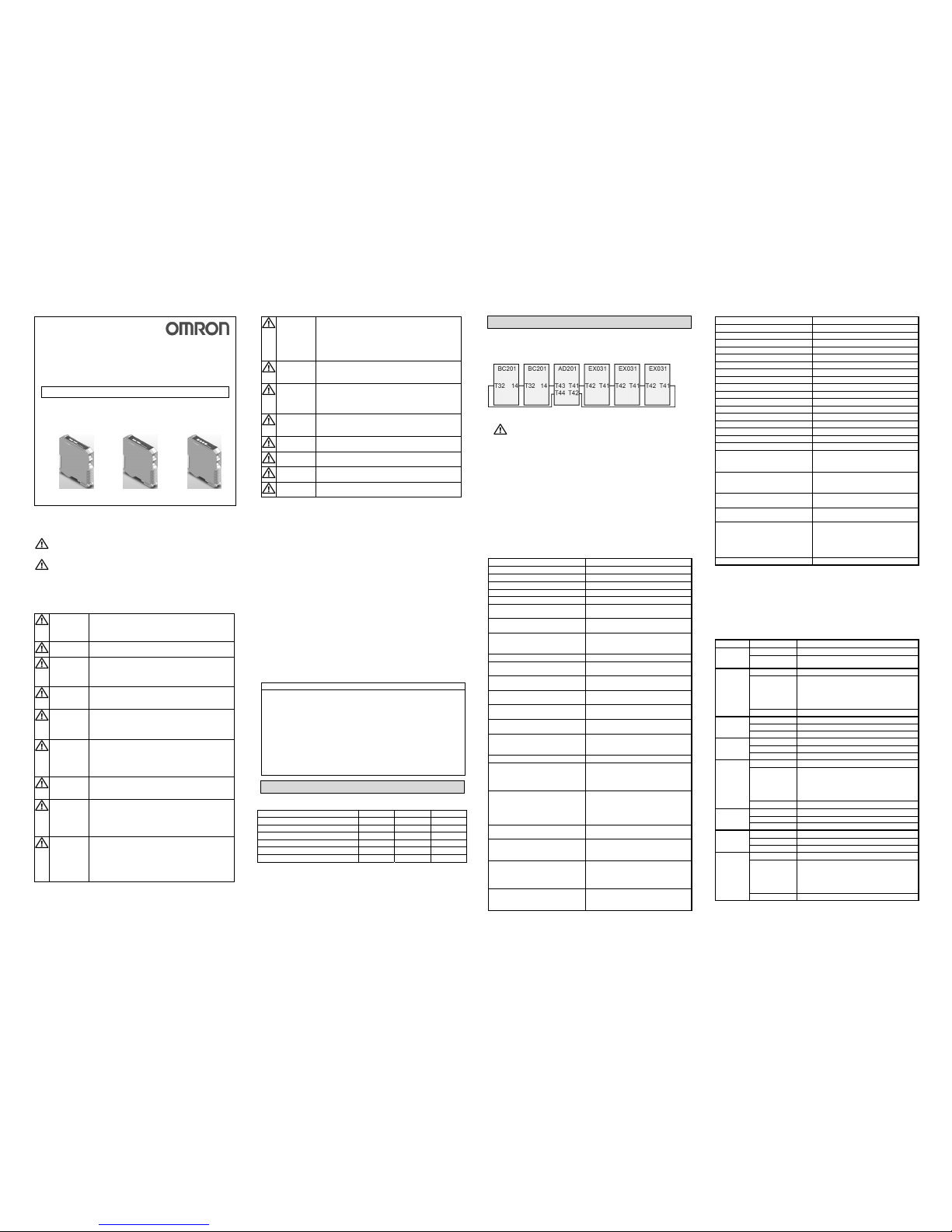
LEDs BC201-□, AD201-□, EX031-□-□
LED / for Status Meaning
POWER
= Power
BC,AD,EX
Green Lit Power supply correctly applied
Not Lit No power or internal error
COM
EX
Yellow Lit Valid communication signal in or out
Yellow Flashing On- or Off-delay in progress
Fast blinking & ERR fast blinking
= Communication error of another unit
Slow blinking & ERR slow blinking
= Communication error of this unit
Not Lit No valid input signal @ T42
IN1
= Input1
BC,AD
Yellow Lit A valid input signal @ T12
Yellow Flashing n.a.
Not Lit No valid input signal @ T12
IN2
= Input1
BC,AD
Yellow Lit A valid in put signal @ T22
Yellow Flashing n.a.
Not Lit No valid input signal @ T22
RESTART
= Restart
BC,AD
Yellow Lit Restart input is activated
Yellow Flashing Error situation
Fast blinking & ERR fast blinking
= Communication error of another unit
Slow blinking & ERR slow blinking
= Communication error of this unit
Not Lit Restart action not required / not allowed
EDM =
ExDevMo
BC,AD,EX
Yellow Lit Extern al Device Monitor enabled
Yellow Flashing External Device Monitor error
Not Lit External Device Monitor disabled
ON
= Outputs
BC,AD,EX
Green Lit
Outputs
activated
Green Flashing Input-loop OK
Not Lit Outputs de- activated
OFF/ERR
= Error
BC,AD,EX
Red Lit OSSDs de-activated
Red Flashing Error. Check LEDs (EDM, Res, Com)
Fast blinking & ERR fast blinking
= Communication error of another unit
Slow blinking & ERR slow blinking
= Communication error of this unit
Not Lit Internal checks OK and OSSD activated
Page 2
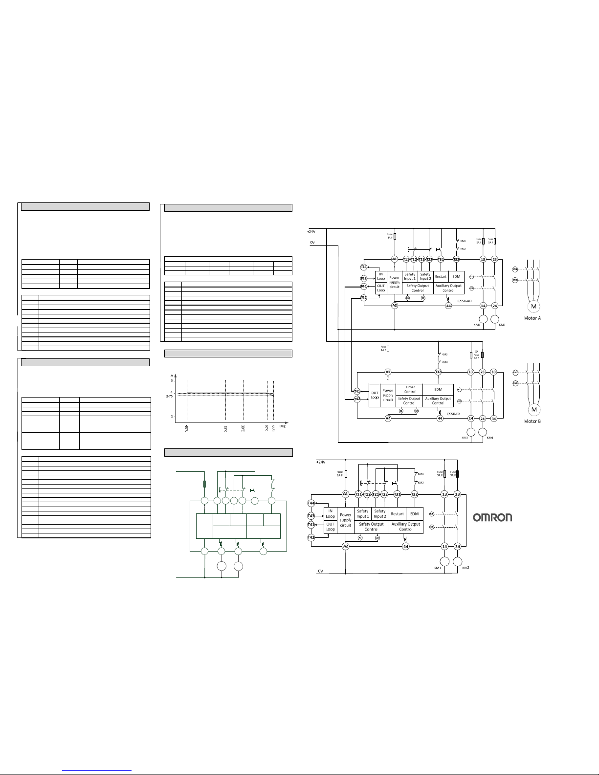
Derating curve of relay contact current
Wiring Examples
G9SR unit: BC201-□ (BC = Basic)
The BC201-□ unit can handle one double-channel input device and 2
output signals. The outputs must be DC loads with a maximum of 2A
switching current each.
This unit can be used stand-alone or as an Input extension for the AD.
In input extension application BC201 can be supplied using a separate
power supply.
Refer to the Operation Manual for more detailed information.
DIP switches for BC201-□
Both dip-switch groups should be set identically.
Function Switch BC201-□
Restart 1 ON = Auto restart OFF = Manual restart
Dynamic Input Test 2 ON = Enabled OFF = Disabled
EDM 3 ON = Enabled OFF = Disabled
Input loop 4 ON = Enabled OFF = Disabled
Aux Outputs 5 ON = Aligned OFF = Inverted
Connections for BC201-□
Label Description
T12 Input Channel 1
44 Output Auxiliary (Status)
A1 Power Supply
T31 Restart Input
T11 Test Signal 1
A2 Power Supply GND
T32 EDM Input or Input Loop IN (depending on dip switches)
T21 Test Signal 2
14 Output 1 OSSD1 or Input Loop OUT (depending on dip switches)
24 Output 2 OSSD2
T22 Input Channel 2
G9SR unit: AD201-□ (AD = Advanced)
The AD201-□ unit can handle one double-channel input device and 2
output signals. Output relays for max. 250V AC 4A for AC1 loads. This
unit can be expanded with max. 3 EX031-□-□ units to handle more output
signals and max. 2 BC201-□ units to handle more input signals.
DIP switches for AD201-□
Both dip-switch groups should be set identically.
Function Switch AD201-□
Restart 1 ON = Auto restart OFF = Manual restart
Dynamic Input Test 2 ON = Enabled OFF = Disabled
EDM 3 ON = Enabled OFF = Disabled
INPUT LOOP 4/5 OFF/OFF = 0 BC201-□ connected
OFF/ON = Setting not allowed
ON/OFF = 1 BC201-□ connected
ON/ON = 2 BC201-□ connected
OUTPUT LOOP 6/7 OFF/OFF = 0 EX031-□-□ connected
OFF/ON = 1 EX031-□-□ connected
ON/OFF = 2 EX031-□-□ connected
ON/ON = 3 EX031-□-□ connected
Connections for AD201-□
Label Description
13 Relay Output 1.1 (NO)
23 Relay Output 2.1 (NO)
T12 Input Channel 1
44 Output Auxiliary (Status)
A1 Power Supply
T31 Restart Input
T11 Test Signal 1
T43 Input loop IN
T44 Input loop OUT
A2 Power Supply GND
T32 EDM input
T21 Test Signal 2
T41 Output loop OUT
14 Relay Output 1.2 (NO)
24 Relay Output 2.2 (NO)
T22 Input Channel 2
T42 Output loop IN
G9SR unit: EX031-T90-□ (EX = Extension)
The EX031-T90-□ unit can be connected to the AD201-□ unit as an
Output extension unit. Outputs are switched with relays designed for 250V
AC with a maximum of 4A switching current for AC1 loads.
The output signals of the EX031-T90-□ unit can be switched with 16 timing
presets for an ON-delay and 16 timing presets for an OFF-delay.
Rotary switches for EX031-T90-□
Switches 1 and 3 set the ON-delay.Both switches should be set identically
Switches 2 and 4 set the OFF-delay. Both switches should be set
identically.
Setting = Seconds
0 = 0s 1 = 0.1s 2 = 0.2s 3 = 0.5s 4 = 1s 5 = 1.5s
6 = 2s 7 = 2.5s 8 = 5s 9 = 10s A = 20s B = 30s
C = 45s D = 60s E = 75s F = 90s
Connections for EX031-T90-□
Label Description
13 Relay Output 1.1 (NO)
23 Relay Output 2.1 (NO)
33 Relay Output 3.1 (NO)
44 Output Auxiliary (Status )
A1 Power Supply
A2 Power Supply GND
T32 EDM Input
T41 Output Loop OUT
14 Relay Output 1.2 (NO)
24 Relay Output 2.2 (NO)
34 Relay Output 3.2 (NO)
T42 Output Loop IN
Use the derating curve to determine the maximum allowed relay contact
current for the actual operating temperature of the unit.
When mounting multiple units close to each other, the rated current will be
2A. Do not apply current higher than 2A. If the rated current is higher than
2A please follow installation instructions in the manual (2.2)
Wiring example for G9SR-BC
Wiring example for G9SR-EX (and G9SR-AD)
Remarks:
Use one power supply for both units.
The bold lines connect the G9SR-EX unit
Wiring example for G9SR-AD
Power
supply
circuit
Safety
Input 1
Safety
Input 2
Restart EDM
Safety Output
Control
Auxiliary Output
Control
T32T31T22T21T12
A1
A2 14 24 44
KM1 KM2
T11
KM1
KM2
+24V
0V
Fuse
5A F
OMRON EUROPE B.V.
Wegalaan 67-69, NL- 2132 JD Hoofddorp
The Netherlands
Tel: (+31) 23-5681300 / Fax: (+31) 23-5681388
Note: These are the Original Instructions.
Note: This Instruction sheet and the product specifications
are subject to change without notice.
 Loading...