


eV+3
User's Manual
I651-E-02

Copyright Notice
The information contained herein is the property of Omron Robotics and Safety Technologies, Inc., and
shall not be reproduced in whole or in part without prior written approval of Omron Robotics and Safety
Technologies, Inc.. The information herein is subject to change without notice and should not be construed as a commitment by Omron Robotics and Safety Technologies, Inc. The documentation is periodically reviewed and revised.
Omron Robotics and Safety Technologies, Inc., assumes no responsibility for any errors or omissions in
the documentation.
Copyright Omron Robotics and Safety Technologies, Inc. by OMRON Corporation. All rights reserved.
Sysmac and SYSMAC are trademarks or registered trademarks of OMRON Corporation in Japan and
other countries for OMRON factory automation products.
EtherCAT® is a registered trademark and patented technology, licensed by Beckhoff Automation GmbH,
Germany.
DeviceNet is a trademark of ODVA.
Other company names and product names in this document are the trademarks or registered trademarks
of their respective companies.
Created in the United States of America.

Table of Contents
Chapter 1: Introduction 9
1.1 Intended Audience
1.2 Related Manuals
1.3 System Overview
The eV+ Operating System 10
The eV+Language 10
1.4 eV+ Keywords
1.5 Monitor CommandPrograms and V+programs
1.6 eV+ File Management
File Name Requirements 12
File Types 12
Programs and Subroutines 13
11
12
12
Chapter 2: Keyword Usage 15
2.1 Using Function Keywords
Function Keyword Syntax 15
Variable Assignments and Data Types 15
Using Functions as KeywordParameters 15
Function Keywords Used Within Expressions 16
2.2 Using Monitor Command Keywords
Monitor Command Keyword Syntax 16
2.3 Using Program Command Keywords
Program Command Keyword Syntax 17
2.4 Using System Parameter Keywords
Available System Parameters 18
Viewing and Setting System Parameters 19
2.5 Using System Switch Keywords
Available System Switches 20
Viewing and Setting System Switches 21
15
16
17
18
20
9
9
9
Chapter 3: eV+ System Operations 23
3.1 System Messages
Message Types 23
Message Handling 23
3.2 Digital I/O Control
I/OUsageConsiderations 24
Basic I/O Control 24
Soft Signals 25
3.3 Disk I/O Operations
22352-000 Rev. B eV+3User'sManual 3
23
24
25

Logical Unit Numbers 25
I/O Operation Error Status 25
Attaching and Detaching Logical Units 26
Attaching and Detaching Disk Devices 26
Reading and Writing with I/O Devices 27
Input Wait Modes 28
Output Wait Modes 28
Disk File Operations 28
Advanced Disk Operations 31
Chapter 4: Motion Control Operations 33
4.1 Motion Control Overview
4.2 Joint-interpolated Motion vs. Straight-line Motion
4.3 Safe Approaches and Departures
4.4 Continuous-Path Trajectories
4.5 Breaking Continuous-Path Operation
4.6 Procedural Motion
4.7 Motion Control Timing Considerations
4.8 Robot Speed and Performance
Robot Speed 37
Robot End-effector / Tool Tip Speed Considerations 38
Robot Performance 38
4.9 Motion Modifiers
33
33
33
34
35
36
37
37
38
Chapter 5: Variables and Data Types 41
5.1 Variable Creation
5.2 Variable Classifications
Variable Classification Scope 41
External Variables 43
Global Variables 44
Local Variables 45
Automatic Variables 45
5.3 Variable Name Requirements
5.4 Variable Initialization
5.5 Variable Operators
Assignment Operators 47
Mathematical Operators 47
Relational Operators 48
Logical Operators 48
String Operators 49
Order of Evaluation 49
5.6 Numeric Representation
Numeric Expressions 50
5.7 String Data Types
ASCII Values 51
41
41
46
46
47
50
50
4 eV+3User'sManual 22352-000 Rev. B

5.8 Real Integer Data Types
Real and Integer Value Ranges 51
5.9 Logical Constants
5.10 Location Data Types
Creating Location Variables 53
Modifying Location Variables 53
5.11 Arrays
Global Array Access Restriction 56
5.12 Variable Context
Interpretation of Context Specification for Variables 58
51
52
52
55
56
Chapter 6: Monitor CommandPrograms 59
6.1 Monitor Command Program Overview
6.2 Monitor CommandProgram Names
6.3 Monitor CommandProgram Contents
6.4 Executing Monitor CommandPrograms
Executing Monitor CommandPrograms from the Monitor Window 60
Autostarting a Monitor CommandProgram 60
Monitor CommandProgram Processing 61
59
59
59
60
Chapter 7: V+programs 63
7.1 V+program Format
Program Lines 63
Program Structure 64
7.2 V+ Program Execution
Program Tasks 64
V+program Processing 66
7.3 Program Control
Unconditional Branching 67
Conditional Branching 68
Looping Structures 69
Loading Programs and Variables to SystemMemory 71
Removing Programs and Variables from System Memory 72
7.4 V+ Program Interrupts
WAIT Program Interrupts 72
WAIT.EVENT Program Interrupts 73
REACT and REACTI Program Interrupts 73
REACTE Program Interrupts 74
HALT, STOP, and PAUSE Program Interrupts 74
Additional Program Interrupt Keywords 75
Program Interrupt Example 75
7.5 V+program Stacks
V+ Program Stack Requirements 77
7.6 Exchanging Information Between V+programs
63
64
66
72
76
78
22352-000 Rev. B eV+3User'sManual 5

Exchanging Information Using Global Variables 78
Exchanging Information Using Soft-signals 78
Exchanging Information Using the Program Argument List 78
7.7 Reentrant and Recursive Programs
Reentrant Programs 81
Recursive Programs 81
7.8 Asynchronous Processing
Error Trapping 82
80
81
Chapter 8: T20 Pendant Programming 83
8.1 Attaching and Detaching the T20 Pendant
8.2 Writing to the T20 Pendant Display
8.3 Detecting User Input
Detecting Pendant Key Presses 84
8.4 Other Pendant Programming Functions
83
83
84
85
Appendix 87
A.1 Warning, Information, and Error Messages
System Warning Messages 87
System Information Messages 87
System Error Messages 88
87
6 eV+3User'sManual 22352-000 Rev. B

Revision History
Revision
Code
A July, 2020 Original release
B August, 2020 Minor corrections and updates
ReleaseDate Details
22352-000 Rev. B eV+3User'sManual 7


This manual contains information that is necessary to use eV+. Please read this manual and
make sure you understand the functionality of eV+ before attempting to use it.
1.1 Intended Audience
This manual is intended for the following personnel, who must also have knowledge of common programming practices and robotic control methods.
l Personnel in charge of introducing FA systems.
l Personnel in charge of designing FA systems.
l Personnel in charge of installing and maintaining FA systems.
l Personnel in charge of managing FA systems and facilities.
1.2 Related Manuals
Use the following related manuals for reference.
Manual Description
Chapter 1: Introduction
Table 1-1. Related Manuals
eV+3KeywordReferenceManual (Cat. No.
I652)
Sysmac Studio Robot Integrated System Building Function with Robot Integrated CPU Unit
Operation Manual (Cat. No. W595)
Robot User Guides User Guide for the robot in use.
T20 Pendant User’s Manual (Cat. No. I601) Describes the use of the optional T20 manual
NJ-series Robot Integrated CPU Unit User's
Manual (Cat. No. O037)
Robot Safety Guide (Cat. No. I590) Contains safety information forOMRON indus-
1.3 System Overview
eV+ is an interpreted programming language and control system for OMRON industrial
robots. This system offers a variety of keywords supporting robot motion, I/O, vision, file operations, and communication with other devices. Real-time interpretation and forward processing of programs in parallel tasks provides continuous path trajectory generation, as well
as on-line program generation, debugging, and modification.
Provides references to eV+ Keyword use and
functionality.
Learning about the operating procedures and
functions of the Sysmac Studio to configure
Robot Integrated System using Robot Integrated CPU Unit.
control pendant.
Describes the settings and operation of the
CPU Unit and programming concepts for
OMRON robot control.
trial robots.
When the eV+ system is used with the NJ-series Robot IntegratedCPUUnit, I/O, logic, safety,
and motion control functions can be created using IEC 61131-3 programming language
22352-000 Rev. B eV+3User'sManual 9
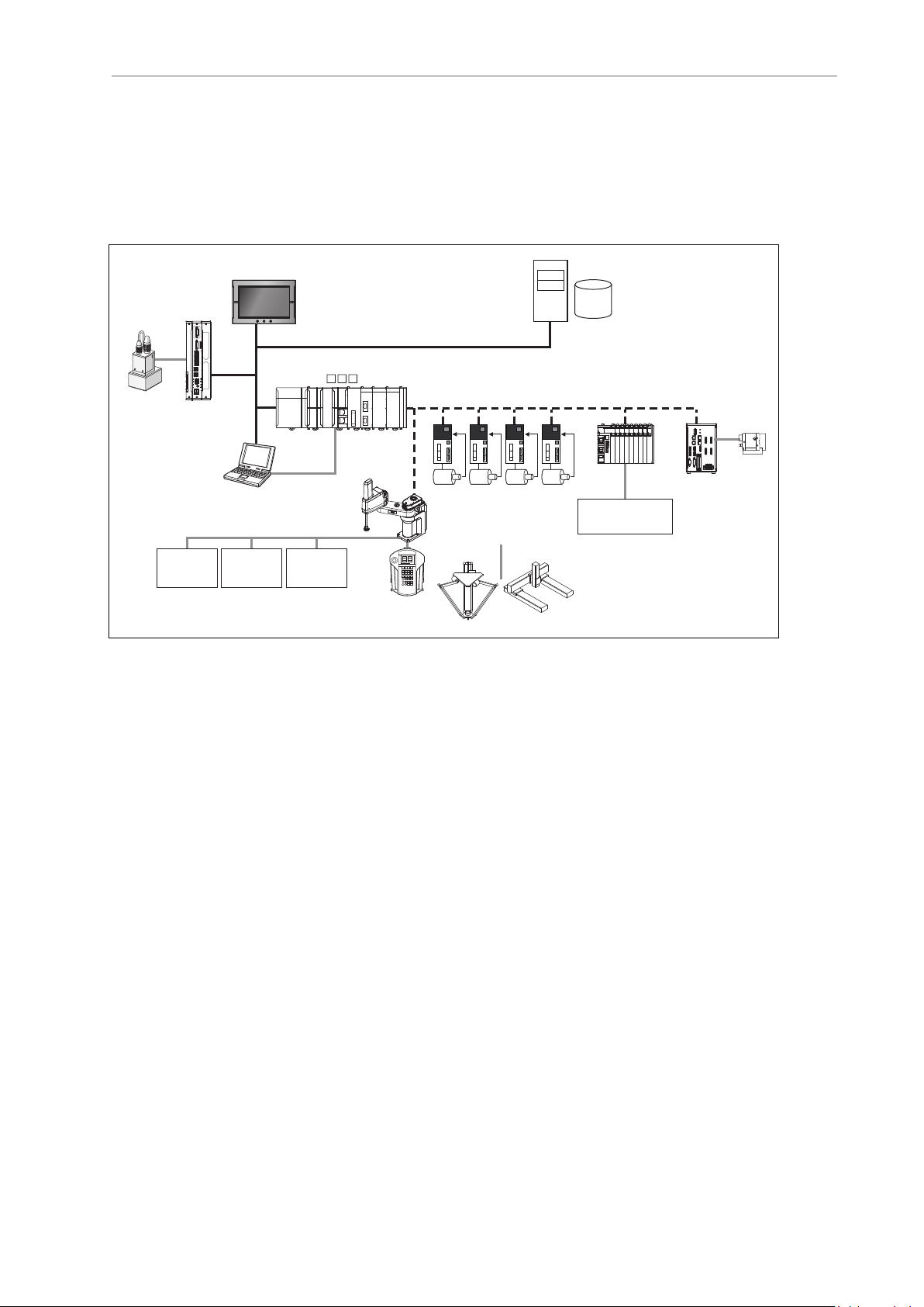
1.3 System Overview
NA-series
PT
Teaching pendant
T20
(with built-in EtherCAT
communications)
Slave
Terminal
Vision sensor
OMRON
robot
Robot Integrated CPU Unit
NJ501-R
I/O control
external devices
1S-series Servo Drives
G5-series Servo Drives
Server
Relational database
USB
Camera
FH-series Vision
Systems
Robots controllable by NJ Robotics function
EtherCAT
Application Controller
Sysmac Studio
EtherNet/IP
Front Panel
Safety
devices
Encoder,
digital I/O
specifications. With the addition of shared variables, shared signals, and function blocks for
interacting with V+ program execution, a user can develop an entire control solution from the
Sysmac Studio software.
The eV+ Operating System runs on OMRON robots while communicating with other system
objects to facilitate programming and runtime functionality. The general system overview is
shown below.
Figure 1-1. System Overview
The eV+ Operating System
The eV+ Operating System is automatically launched when the robot controller and NJ-series
Robot IntegratedCPUUnit are powered ON. The operating system accepts instructions from
application programs, input from workcell peripheral devices, and operator input from the
pendant. The tasks performed by the operating system include the following.
l Managing the execution of application programs.
l Managing the flow of information to and from storage devices.
l Monitoring external devices attached to the controller.
l Reporting errors generated during processing.
The eV+Language
The eV+ language is comprised of keywords that provide control, data manipulation, and
other application-specific functionality. These keywords are used in statements with specific
syntax detailed in this document with examples. Statements are executed in a consecutive
manner until the .END statement is reached. This is referred to as a program cycle. Keywords
may be used to create V+programs or issue individual commands in the Monitor Window.
Refer to the eV+3KeywordReferenceManual (Cat. No. I652) for other syntax and statement
examples.
IMPORTANT: An error "Command not supported"will be returned if a
keyword is issued on a system that does not include the NJ-series Robot
IntegratedCPUUnit as the Host System.
10 eV+3User'sManual 22352-000 Rev. B

1.4 eV+ Keywords
eV+keywords are a set of instructions that are used to perform various operations for a robotbased application. Keywords are used to create statements arranged in steps for the following
programmatic functionality.
l Robot motion control
l Error processing and handling
l Arithmetic functions
l System parameter and switch manipulation
l Data management
l I/O control and external device communication
l Logic and other conditional evaluations
l Subroutine execution and control
l Executing various system functions
l T20 Pendant functions
Depending on the type of keyword, they can be used to build a program or they can be issued
individually using the Monitor Window in the Sysmac Studio.
Keywords are categorized into six types as described below.
Chapter 1: Introduction
Table 1-2. eV+ Keyword Types
Keyword Type Usage
Functionkeywords Used to return values from the eV+ Operating System.
Refer to Using Function Keywords on page 15for more information.
Monitor command
keywords
Other keywords Used to specify units when using the SPEEDprogram command
Program command
keywords
System parameter
keywords
Used to issue individual operations in the Monitor Window or to create
Monitor CommandPrograms.
Refer to Using Monitor Command Keywords on page 16for more information.
keyword.
Refer to the eV+3KeywordReferenceManual (Cat. No. I652) for more
information.
Used to command operations in V+programs.
Refer to Using Program Command Keywords on page 17for more
information.
Used to manipulate system parameters in V+programs or with the Monitor Window.
Refer to Using System Parameter Keywordsfor more information.
System switch
keywords
Used to manipulate system switches in V+programs or with
theMonitor Window.
Refer toUsing System Switch Keywords on page 20for more information.
22352-000 Rev. B eV+3User'sManual 11

1.5 Monitor CommandPrograms and V+programs
Keywords andSyntax
In order for keywords to work with the eV+ operating system, they must be issued with a specific syntax. This syntax generally consists of a keyword and associated parameters in a specific order, separated by characters such as commas, brackets, and parentheses. This syntax is
detailed in this manual and also in the eV+3KeywordReferenceManual (Cat. No. I652). An
example of keyword syntax is shown below.
SET loc_name = SHIFT(loc_value BY 5, 5, 5)
When creating V+programs with the Sysmac Studio, syntax is checked and formatted as the
characters are input. Refer to theSysmac Studio Robot Integrated System Building Function with
Robot Integrated CPU Unit Operation Manual (Cat. No. W595) for more information.
1.5 Monitor CommandPrograms and V+programs
There are two types of programs that the eV+ Operating System can execute: Monitor
CommandPrograms and V+programs.
V+programs contain the logic, motion control, and vision keywords that control a robot during run-time. Refer to V+programs on page 63 for more information.
Monitor CommandPrograms are used to perform system-level functions such as loading files,
changing the default directory path, and executing main eV+ programs after system boot up.
Refer to Monitor CommandPrograms on page 59 for more information.
1.6 eV+ File Management
The eV+ Operating System has a file management system very similar to other operating systems. Each file within a subdirectory must have a unique name. There are several file extensions that are used for different types of files in the eV+ system as described in File Types on
page 12.
New files can be created with the Sysmac Studio or by issuing specific keywords. Refer to the
Sysmac Studio Robot Integrated System Building Function with Robot Integrated CPU Unit Operation
Manual (Cat. No. W595) and the eV+3KeywordReferenceManual (Cat. No. I652) for more inform-
ation.
File Name Requirements
The eV+file name requirements are described below.
l File names can have a maximum of eight characters.
l File names must have an extension (file type) designation that is 1 to 3 characters in
length. Refer to File Types on page 12 for more information.
l File names can only include alphanumeric characters and the underscore (_) character.
No other special characters are permitted.
l File names cannot contain blank spaces.
l Keywords cannot be used as file names. Do not name files the same as any keywords.
NOTE: File names are not case-sensitive.
File Types
There are several file types that are used by the eV+ Operating System. File types that are used
during system development, commissioning, debugging, and other typical operations are listed below.
12 eV+3User'sManual 22352-000 Rev. B

Chapter 1: Introduction
IMPORTANT: Direct access and editing of these files is not necessary under normal use.
Table 1-3. eV+ File Type Descriptions
File
Type
.v2
.cal System calibration data files.
.xml Robot specification and other parameter files.
.rtf Text files (Readme).
.pg V+program or group of programs (module)
V+ programs
Global variables referenced by the programs and subroutines can be stored in the file.
All of the subroutines referenced (directly or indirectly) by the specified program can be
stored in the file.
Refer to the eV+3KeywordReferenceManual (Cat. No. I652) for information about
storing programs and variables in a disk file using the STOREkeyword.
Refer to the Sysmac Studio Robot Integrated System Building Function with Robot
Integrated CPU Unit Operation Manual (Cat. No. W595) for information about saving
programs and variables to the controller.
In addition to the programs specified to store in the file, any subroutines referenced by
those programs are also stored in the file.
Refer to the eV+3KeywordReferenceManual (Cat. No. I652) for information about
storing programs and variables in a disk file using the STOREPand STOREM keywords.
Description
Programs and Subroutines
V+ is an interpreted language, therefore linking and compiling are not required. Main programs and subroutines always exist as separate programs. The eV+ file structure allows you to
keep a main program and all the subroutines it calls or executes together in a single file so that
when a main program is loaded, all the subroutines it calls are also loaded. A single file that
contains a program and subroutines is also referred to as a module.
If a program calls a subroutine that is not resident in system memory, the error *Undefined program or variable name* will result.
Additional Information: Refer to the STORE_andMODULEkeyword descriptions in the eV+3KeywordReferenceManual (Cat. No. I652) for more information.
Refer to the Sysmac Studio Robot Integrated System Building Function with Robot
Integrated CPU Unit Operation Manual (Cat. No. W595) for more information about
creating a program file.
22352-000 Rev. B eV+3User'sManual 13


This chapter describes how to use the different types of keywords with the eV+ system.
2.1 Using Function Keywords
Function keywords are issued within V+ Program statements and can be used in several different ways as described below.
Additional Information: Refer to the eV+3KeywordReferenceManual (Cat. No.
I652) for more information about specific function keywords.
Function Keyword Syntax
eV+ provides you with a wide variety of predefined function keywords for performing string,
mathematical, and other data manipulation. In most cases, you must provide the data that is
input to a function keyword. The keyword then returns a value based on a specific operation
on that data. Function keywords can be used anywhere that a value or expression would be
used.
Correct syntax for function keywords must be observed when creating statements in V+ programs. If incorrect syntax is used, eV+ will return an *Illegal monitor command* error.
Chapter 2: Keyword Usage
Variable Assignments and Data Types
When a function keyword is issued, a value is returned by the eV+ Operating System. The data
type of the value that is returned must match the data type of the variable that is assigned to
the function. For example, if the $TIME function keyword is issued, eV+ will return a string
data type value. The examples below demonstrate various data types used with variable
assignments.
$current_time = $MID($TIME(,time),11,8)
SET #pos1 = #PHERE
SETBELT %main.belt = BELT(%main.belt)
Additional Information: Refer to Variables and Data Types on page 41 for more
information
Using Functions as KeywordParameters
A function keyword can be used as a parameter as long as the data type returned by that function is the correct type. For example, consider the SQRT function statement shown below. The
SQRT function keyword uses the syntax "SQRT(value)" for reference.
i = SQRT(SQR(x))
The statement above returns the absolute value of variable "x" and assignes it to variable "i".
Any function that returns a numerical value can be substituted for "SQR(x)"in the statement
above.
22352-000 Rev. B eV+3User'sManual 15

2.2 Using Monitor Command Keywords
Function Keywords Used Within Expressions
A function keyword can be used as an expression as long as the data type returned by that
function is the correct type. For example, consider the IF ... THEN conditional statement shown
below. The IF ... THEN keyword uses the syntax "IF logical_expTHEN" for reference.
IFLEN($string_variable) > 12 THEN
The statement above evaluates the expression "LEN($string_variable) > 12". This expression
includes the LENfunction keyword that returns the number of characters in the variable
"$string_variable". Any function that returns a numerical value can be substituted for LEN
($string_variable) in the statement above.
2.2 Using Monitor Command Keywords
Monitor command keywords can be issued in the Monitor Window or with the use of a Command Program. Most monitorcommand keywords include at least one parameter that controls
how the eV+ system executes the operation. This additional information is specified when the
keyword is issued in the Monitor Window. Parameters must be entered in the order they are
listed and they must use correct syntax.
Additional Information: Refer to the eV+3KeywordReferenceManual (Cat. No.
I652) for more information about specific monitorcommand keywords.
Refer to the Sysmac Studio Robot Integrated System Building Function with Robot
Integrated CPU Unit Operation Manual (Cat. No. W595) for more information about
the Monitor Window.
Monitor Command Keyword Syntax
Correct syntax for monitorcommand keywords must be observed when creating statements in
V+ programs. If incorrect syntax is used, eV+ will return an *Illegal monitor command* error.
In general, monitorcommand keywords have the following formats. The keyword is shown in
uppercase and the arguments are shown in lowercase. Required keywords, parameters, and
symbols such as equal signs and parentheses are shown in bold text. Optional keywords, parameters, and symbols are shown in regular text.
KEYWORD
KEYWORD req_param
KEYWORD (req_param)
KEYWORD opt_param
KEYWORD opt_param1, opt_param2, ... , opt_paramX
KEYWORD req_param, opt_param = value
KEYWORD @task:program_step(expression)
KEYWORD req_param1 = req_param2
KEYWORD req_param1 = req_param2 KEYWORD opt_param
Additional Information: All required or optional monitorcommand keyword
parameters and associated syntax is described for each keyword in the
eV+3KeywordReferenceManual (Cat. No. I652). Refer to specific keyword details in
that manual for more information.
16 eV+3User'sManual 22352-000 Rev. B

Chapter 2: Keyword Usage
Monitor Command Keyword Parameter Entry
Monitor command keyword parameters can be optional or required. If a parameter is required,
a value must be entered on the command line or the command will not execute correctly. A
space is required between the keyword and the parameters that follow it. A comma is typically
used to separate parameters but some monitorcommand keywords may require an equal sign
(=) assignment operator.
If a parameter is optional, its value can be omitted and the system will substitute a default
value. For example, the STATUSmonitorcommand keyword can be issued as shown below.
The STATUSsyntax is "STATUSselect" for reference, where "select" is an optional parameter.
STATUS
Issuing the STATUS monitorcommand keyword as shown above will return status information for all the program tasks.
Issuing the STATUSmonitorcommand keyword with a parameter value as shown below will
return status information for only system task number 1.
STATUS 1
Spaces before and after parameter separators are optional. If one or more parameters follow an
omitted parameter, the parameter separator(s) must be typed. If all the parameters following an
omitted parameter are optional, and those parameters are also omitted, the separators do not
need to be typed. Refer to the example below that demonstrates these concepts. The XSTEP syntax is "XSTEP task program (param_list), cycles, step" with all parameters being optional, for
reference.
XSTEP assembly,,23
2.3 Using Program Command Keywords
Program command keywords are used to create V+ programs for robot control and other functions such as I/O control, file operations, error handling, and data management. This section
provides details about the usage of program command keywords when creating V+ programs.
Program Command Keyword Syntax
Correct syntax for program command keywords must be observed when creating statements in
V+ programs. If incorrect syntax is used, the statement will cause errors in the V+ Editor and
the program cannot be executed.
Symbols such as commas, brackets, and parentheses may be required for program
commandkeyword syntax when parameters are present. program command keywords may
contain parameters that define or specify information needed for the operation. Some program
command keywords do not require any parameters while other program command keywords
have required or optional parameters.
In general, program command keywords have the following formats (not an exhaustive listing). The keyword is shown in uppercase and the arguments are shown in lowercase.
Required keywords, parameters, and symbols such as equal signs and parentheses are shown
in bold text. Optional keywords, parameters, and symbols are shown in regular text.
KEYWORD
KEYWORD req_param
KEYWORD opt_param
KEYWORD (parameter)opt_param
22352-000 Rev. B eV+3User'sManual 17

2.4 Using System Parameter Keywords
KEYWORD opt_param1, opt_param2, ... , opt_paramX
KEYWORD req_param, opt_param = value
KEYWORD req_param1 = req_param2
KEYWORD req_param1 = req_param2 KEYWORD opt_param
Additional Information: All required or optional program commandkeyword
parameters and associated syntax is described for each keyword in the
eV+3KeywordReferenceManual (Cat. No. I652). . Refer to a specific keyword
details in that manual for more information.
No Required Parameters
Some program commandkeywords do not require any parameters such as LEFTY, RIGHTY,
ABOVE, and BELOW. Keywords that do not require parameters can be used as shown below.
ABOVE
MOVE point1
BREAK
Required or Optional Parameters
Some program commandkeywords have parameters that are required or optional. When
using a keyword that uses multiple parameters, symbols such as commas, brackets, and parentheses may be required. If required parameters or syntax is incorrect, an error will occur.
Refer to Warning, Information, and Error Messages on page 87 for error information and the
eV+3KeywordReferenceManual (Cat. No. I652) for more information about the use of symbols to
complete the correct syntax for eV+.
NOTE: When program lines are entered, extra blank spaces can be used
between any elements in the line. The eV+ editor adds or deletes spaces in program lines to make them conform with the standard spacing. The editors also
automatically format the lines to uppercase for all keywords and lowercase for
all user-defined names.
2.4 Using System Parameter Keywords
System parameters determine certain operating characteristics of the eV+ system. These parameters have numeric values that can be changed from the Monitor Window or from within a
program to suit particular system configurations and needs. The various parameters are
described in this section along with the operations for displaying and changing their values.
Available System Parameters
Use the following table to understand the available system parameters and their basic functions. Refer to the eV+3KeywordReferenceManual (Cat. No. I652) for setting details, examples,
and other information.
Table 2-1. System Parameter Details
Parameter Description
BELT.MODE Set characteristics of the conveyor tracking feature of the eV+ system.
DEVIATION Adds a path deviation from 1 to 100% to the motion in the singularity
region when a robot is in singularity.
18 eV+3User'sManual 22352-000 Rev. B

Chapter 2: Keyword Usage
Parameter Description
NOT.CALIBRATED Represents the calibration status of the robot(s) controlled by the eV+ sys-
tem.
VTIMEOUT Sets a timeout value so that an error message is returned if no response is
received following a vision command.
JOG.TIME Sets the keep-alive time of a jog operation.
Each time a jog operation is executed, this parameter setting specifies the
time the axis or joint moves.
Viewing and Setting System Parameters
System parameters can be viewed and set in the Monitor Window. They can also be controlled
by V+ programs. Use this section to understand how to view and set system parameters.
Viewing and Setting System Parameters with the Monitor Window
The PARAMETERmonitorcommand keyword is used to view and set parameter values as
shown in the examples below.
Viewing Parameter Values
The following example will display all parameters and their current values in the Monitor
Window.
PARAMETER
The following example will display the BELT.MODEparameter current value in the
MonitorWindow.
PARAMETER BELT.MODE
Setting Parameter Values
The following example will set theBELT.MODEparameter to 4.
PARAMETER BELT.MODE = 4
Reading and Writing System Parameters with V+ Programs
Parameters can be set during V+ program execution by using the PARAMETER program command keyword.
NOTE: It is common practice to use a Monitor CommandProgram to set parameters. Refer to Monitor CommandPrograms on page 59 for more information.
The following program statement will set the BELT.MODE system parameter to have bits 1
and 3 set to 1 (mask values 1 + 4) using thePARAMETERprogram command keyword.
PARAMETER BELT.MODE = 5
A parameter value can be returned during V+ program execution or using the Monitor Window.
The following program statement will return the current setting of the BELT.MODE system
parameter in the Monitor Window.
22352-000 Rev. B eV+3User'sManual 19

2.5 Using System Switch Keywords
TYPE "The BELT.MODE parameter is set to", PARAMETER(BELT.MODE)
2.5 Using System Switch Keywords
System switches determine certain operating characteristics of the eV+ system. These switches
can be turned ONor OFF from the Monitor Window or from within a program.. The various
system switches are described in this section along with the operations for displaying and controlling them.
Available System Switches
Use the following table to understand the available system switches and their basic functions.
Refer to the eV+3KeywordReferenceManual (Cat. No. I652) for settings, details, examples, and
other information.
Switch Description
AUTO.POWER.OFF When this switch is ON, errors will disable high power. When this switch
is OFF, these errors stop the robot and signal the eV+ system, but do not
cause high power to be turned OFF.
The errors are defined as follows.
l (-624) *force protect limit exceeded*
l (-1003) *Time-out nulling errors* Mtr
l (-1006) *Soft envelope error* Mtr
CP Enables or disables continuous-path motion processing. Refer to Continu-
ous-Path Trajectories on page 34 for more information.
DECEL.100 Enables or disables the use of 100 percent as the maximum deceleration
for the ACCEL program command keyword.
DELAY.IN.TOL Controls the timing of coarse or fine nulling after eV+ completes a
motion segment (positioning tolerance). Refer to COARSEandFINE
programcommand keyword details.
DRY.RUN This switch enables or disables the transmission of motion commands to
the robot. Turn this switch ON to test programs for proper logical flow and
external communication functionality to prevent collisions.
NOTE: The T20 pendant can still be used to move the
robot when DRY.RUN is enabled if there is no task attached
to the robot. Otherwise, a Robot Interlocked error (-621)
will occur.
MESSAGES Setting this switch to ON will allow messages to be displayed on the Mon-
itor Window while using theTYPE program command keyword.
Setting this switch OFFwill prevent messages from being displayed on
the Monitor Window with the TYPE program command keyword.
OBSTACLE Enables or disables up to 4 different obstacles that are defined for a robot.
POWER This switch controls and displays the robot high power. This switch is
automatically enabled whenever robot high power is turned ON.
If the robot timing specifications in the system configuration is non-zero,
enabling high power is a two-step process. In this case, after enabling
high power from the T20 Pendant, Monitor Window, or software, the sys-
20 eV+3User'sManual 22352-000 Rev. B

Chapter 2: Keyword Usage
Switch Description
tem flashes the high power indicator for the duration of the timing specification setting (in seconds). If a timeout occurs, the message
*HIGHPOWERbutton not pressed*will appear.
Refer to Warning, Information, and Error Messages on page 87 for more
information.
Refer to the Sysmac Studio Robot Integrated System Building Function
with Robot Integrated CPU Unit Operation Manual (Cat. No. W595) for
more information about robot timing specification settings.
ROBOT Enables or disables one robot or all robots.
SCALE.ACCEL Enables or disables the scaling of acceleration and deceleration as a func-
tion of program speed as long as the program speed is below a preset
threshold.
SCALE.ACCEL.ROT Specifies whether or not the SCALE.ACCEL system switch accounts for
the cartesian rotational speed during straight-line motions.
UPPER Determines whether comparisons of string values will consider lowercase
letters the same as uppercase letters. When this switch is ON, all lowercase letters are considered as though they are uppercase.
Viewing and Setting System Switches
System switches can be viewed and set in theMonitorWindow. Then can also be controlled
by V+ programs. Use this section to understand how to view and set system switches.
Viewing and Setting System Switches from the Monitor Window
The SWITCH monitorcommand keyword is used to view and set switches as shown in the
examples below.
Viewing System Switches
The following example will display all switches and their current values in the Monitor Window.
SWITCH
The following example will display the POWER switch current state in the MonitorWindow.
SWITCH POWER
Setting SystemSwitches
The following example will turn ON the AUTO.POWER.OFF switch.
ENABLE AUTO.POWER.OFF
The following example will turn OFF the AUTO.POWER.OFFswitch.
DISABLE AUTO.POWER.OFF
22352-000 Rev. B eV+3User'sManual 21


Chapter 3: eV+ System Operations
The following sections describe various eV+system operations.
3.1 System Messages
System messages have designated numbers and strings for identification. These can be used to
detect and recover from various eV+ conditions with V+ programs or using the Monitor Window.
Additional Information: Refer to Warning, Information, and Error Messages on
page 87
Message Types
There are three different message types:
l Informational messages (message numbers 0 to 49)
l Warning messages (message numbers 50 to 299)
l Error messages (messages with negative values)
System Behavior
The eV+ system will behave differently depending on the type of message and eV+ state when
the message occurs.
Informational andwarning messages do not impact the system operation and can be used for
observational purposes.
Errors messages have an impact on system operation. They will not completely stop the eV+
system, but individual tasks associated with the error will stop running.
System behavior after errors occur depend on the running task, robot status, and type of error.
If the robot is running and on the same task where an error occurs, the robot will be stopped
with maximum deceleration and an error message(s) will be generated. If an error occurs on a
task that is not running a robot, only this task will be stopped and the robot will not be
affected.
Message Handling
eV+ will internally store system message information in order to be accessed with the ERROR
and REACTEkeyword operations.
The following information is stored for access using the ERRORkeyword operation.
l The last system message of a task (current or selected)
l The last system message of each attached robot
l The last message of the eV+ system
l A category, source, and name for each system message.
Additional Information: Refer to the eV+3KeywordReferenceManual (Cat. No.
I652) for more information about the ERROR and REACTEkeyword operations.
22352-000 Rev. B eV+3User'sManual 23

3.2 Digital I/O Control
3.2 Digital I/O Control
When eV+ starts, blocks of system memory are assigned to internal and external digital I/O
detected by the system.
Several program command keywords are available for digital I/Ocontrol purposes. Digital
input signals can be monitored for changes and outputs can be turned ON and OFF conditionally.
Refer to the robot user guide for more information about default signal allocation.
I/OUsageConsiderations
The RESETand DEF.DIO program command keywords have no effect on Host I/Osignal numbers 4001 to 4999.
The IOmonitor command keyword will return the value of signals that are mapped in the
host and returns "-"for signals that are not mapped.
The SIG.INSfunction keyword will return TRUE if the host signal is available and FALSEif it
is not available (not mapped).
Refer to the eV+3KeywordReferenceManual (Cat. No. I652) for more information.
Basic I/O Control
Use the following examples to understand basic I/Ocontrol functionality with program command keywords.
Input Signal Examples
The following example halts program execution until a switching device attached to digital
input channel 1001 is closed.
WAIT SIG(1001)
The following example evaluates input signal 1002 and calls a program "service.feeder" when
the signal turns ON.
IF SIG(1002) THEN
CALL service.feeder()
END
NOTE: The example above will call "service.feeder" if signal 1002 is ON only
when the condition is evaluated.
Output Signal Examples
The following example turns OFFdigital output signal 33.
SIGNAL(-33)
The following example turns ON digital output signal 33.
SIGNAL(33)
The following example controls multiple digital output signals with a single statement.
SIGNAL(33),(-34),(35)
24 eV+3User'sManual 22352-000 Rev. B

Soft Signals
Soft signals are provided in the range of 2001 to 2999. These signals are accessible with all V+
programs and can be used with the SIG and SIGNALkeywords for interaction between V+ programs on different tasks or interaction between V+ programs and functionality in an
ApplicationManager..
3.3 Disk I/O Operations
The following sections describe the basic procedures and functions for disk I/O operations.
Logical Unit Numbers
All eV+ disk I/Ooperations reference an integer value called a Logical Unit Number (LUN).
The LUN provides a method of identifying which device or file is being referenced by an
I/Ooperation. A LUN device can refer to a robot, a disk, a TCP protocol device driver, a
TFTPserver, or a UDP protocol device driver.
The LUNspecifier is a parameter used in several keywords listed below. Refer to the
eV+3KeywordReferenceManual (Cat. No. I652) for more information.
The following program command keywords use the LUN parameter.
Chapter 3: eV+ System Operations
l ATTACH
l DETACH
l FCMND
l FOPEN
l FSET
l READ
l WRITE
I/O Operation Error Status
Unlike most other eV+ keywords, I/O operations are expected to fail under certain circumstances. For example, when reading a file, an error status is returned to the program to
indicate when the end of the file is reached. The program is expected to manage this error and
continue execution.
For these reasons, eV+ I/O keywords normally do not stop program execution when an error
occurs. Instead, the success or failure of the operation is saved internally for access by the
IOSTAT real-valued function. For example, a reference to IOSTAT(5) returns a value indicating
the status of the last I/O operation performed on LUN 5. The values returned by IOSTAT fall
into one of following three categories.
Table 3-1. IOSTATKeyword Return Values
Value Description
1 The I/O operation completed successfully.
0 The I/O operation has not yet completed. This value appears only if
a pre-read or no-wait I/O operation is being performed.
<0 The I/O operation completed with an error. The error code indic-
ates what type of error occurred.
Additional Information: Refer to Warning, Information, and Error Messages on
page 87 The $ERROR string function keyword can be used in a program (or with
22352-000 Rev. B eV+3User'sManual 25

3.3 Disk I/O Operations
the LISTS monitor command keyword) to generate the text associated with most
I/O errors.
NOTE: It is not necessary to use IOSTAT after use of a GETC keyword since
errors are returned directly by the GETC keyword.
Attaching and Detaching Logical Units
An I/O device must be attached using the ATTACH program command keyword before it can
be accessed by a program. Once a specific device (such as the teach pendant) is attached by
one program task, it cannot be used by another program task.
Most I/O requests fail if the device associated with the referenced Logical Unit Number is not
attached. When a program is finished with a device, it detaches the device with the DETACH
program command keyword. This allows other programs to process any pending I/O operations.
A physical device type can be specified when the logical unit is attached. If a device type is
specified, it supersedes the default, but only for the logical unit attached. The specified device
type remains selected until the logical unit is detached.
When a control program completes execution normally, all I/O devices attached by it are automatically detached. If a program stops abnormally, most device attachments are preserved. If
the control program task is resumed and attempts to reattach these logical units, it may fail
because of the attachments still in effect.
Additional Information: The KILL monitorcommand forces a program to
detach all the devices that it has attached.
If attached by a program, the Monitor Window and teach pendant are detached whenever the
program halts or pauses for any reason, including error conditions and single-step mode. If the
program is resumed, the Monitor Window and the teach pendant are automatically reattached
if they were attached before the termination.
Attach Request Response Mode
An attach request can optionally specify immediate mode. Normally, an attach request is
queued and the calling program is suspended if another control program task is attached to
the device. When the device is detached, the next attachment in the queue will be processed. In
immediate mode, the ATTACH program command keyword completes immediately with an
error if the requested device is already attached by another control program task.
Attach requests can also specify no-wait mode. This mode allows an attach request to be
queued without forcing the program to wait for it to complete. The IOSTAT function must then
be used to determine when the attach has completed.
If a task is already attached to a logical unit, it will get an error immediately if it attempts to
attach again without detaching, regardless of the type of wait mode specified.
Attaching and Detaching Disk Devices
Use the sections below to understand how to attach and detach disk devices.
Attaching DiskDevices
The type of device to be accessed is determined by the DEFAULT monitor command keyword
or the ATTACH program command keyword. If the default device type set by the DEFAULT
26 eV+3User'sManual 22352-000 Rev. B

Chapter 3: eV+ System Operations
keyword is not appropriate at a particular time, the ATTACH keyword can be used to override
the default.
The following example attaches to an available disk logical unit and returns the number of the
logical unit in the variable "dlun", which can then be used in other disk I/O operations.
ATTACH (dlun, 4) "DISK"
If the device name is omitted from the keyword syntax, the default device for the specified
LUN is used. It is recommended that you always specify a device name with the ATTACH
keyword. The device SYSTEM refers to the device specified with the DEFAULT
monitorcommand. Once the attachment is made, the device cannot be changed until the
logical unit is detached. However, any of the units available on the device can be specified
when opening a file. For example, the eV+ DISK units are A, C and D. After attaching a DISK
device LUN, a program can open and close files on any of these disk units before detaching
the LUN.
Detaching Disk Devices
When a disk logical unit is detached, any disk file that was open on that unit is automatically
closed. However, error conditions detected by the close operation may not be reported. Therefore, it is good practice to use the FCLOSE keyword to close files and to check the error status
afterwards. FCLOSE ensures that all buffered data for the file is written to the disk, and
updates the disk directory to reflect any changes made to the file. The DETACH keyword frees
up the logical unit.
The following example will close a file and detach a disk LUN.
FLCOSE(dlun)
IFIOSTAT(dlun) THEN
TYPE $ERROR(IOSTAT(dlun))
END
DETACH(dlun)
Reading and Writing with I/O Devices
The READ program command keyword processes input from all devices. The basic READ
keyword issues a request to the device attached on the indicated LUN and waits until a complete data record is received before program execution continues. The length of the last record
read can be obtained with the IOSTAT function with its second argument set to a value of 2.
The GETC real-valued function returns the next data byte from an I/O device without waiting
for a complete data record. It is commonly used to read data from the Monitor Window. It also
can be used to read disk files in a byte-by-byte manner. Special mode bits to allow reading
with no echo are supported for Monitor Window read operations.
Monitor Window input can be performed using the PROMPT program command keyword.
The GET.EVENT real-valued function can be used to read input from the Monitor Window.
This may be useful in writing programs that operate on both graphics and non-graphics-based
systems. To read data from a disk device, a file must be open on the corresponding logical
unit. The FOPEN_ program command keywords open disk files.
The WRITE program command keyword processes output to disk devices and to the Monitor
Window. The basic WRITE keyword issues a request to the device attached on the indicated
LUN, and waits until the complete data record is output before program execution continues.
WRITE keywords accept format control specifiers that determine how output data is formatted,
and whether or not an end of record mark should be written at the end of the record.
Monitor Window output can be performed using the PROMPT or TYPE keywords. A file must
be opened using the FOPENW or FOPENA keywords before data can be written to a disk
22352-000 Rev. B eV+3User'sManual 27

3.3 Disk I/O Operations
device. FOPENW opens a new file. FOPENA opens an existing file and appends data to that
file.
Additional Information: Refer to the eV+3KeywordReferenceManual (Cat. No.
I652) for usage considerations, details, and examples of the keywords described
above.
Input Wait Modes
Normally, eV+ waits until the data from an input keyword is available before continuing with
program execution. However, the READ keyword and GETC keyword accept an optional parameter that specifies no-wait mode.
In no-wait mode, these keywords return immediately with the error status -526 (No data
received) if there is no data available. A program can loop and use these operations repeatedly
until a successful read is completed or until some other error is received. The disk devices do
not recognize no-wait mode on input and treat such requests as normal input-with-wait
requests.
Output Wait Modes
Normally, eV+ waits for each I/O operation to be completed before continuing to the next program statement.
The following example causes eV+ to wait for the entire record of 50 spaces to be transmitted
(about 50 ms for 9600 baud rate) before continuing to the next program statement.
TYPE /X50
Similarly, WRITE program command keywords to disk files will wait for any required physical output to complete before continuing.
This waiting is not performed if the /N (no wait) format control specifier is used in an output
keyword. Instead, eV+ immediately executes the next program statement. The IOSTAT function
checks whether or not the output has completed. It returns a value of zero if the previous I/O
is not complete. If a second output keyword for a particular Logical Unit Number is
encountered before the first no-wait operation has completed, the second statement automatically waits until the first is done. This scheme means the no-wait output is effectively
double-buffered. If an error occurs in the first operation, the second operation is canceled, and
the IOSTAT value is correct for the first operation. The IOSTAT function can be used with a
second parameter of 3 to explicitly check for the completion of a no-wait write.
Disk File Operations
Disk file operations that are available with the eV+ system are described below.
The FDIRECTORY monitor command keyword is used to display the names of the files in a
directory. A disk file can be accessed either sequentially, where data records are accessed from
the beginning of the file to its end, or randomly, where data records are accessed in any order.
Refer to Advanced Disk Operations on page 31 for more information about sequential and random access for disk files.
The FCMNDprogram command keyword is used to perform the following operations.
l Rename a file
l Create a subdirectory
l Delete a subdirectory
Additional Information: The FCMND keyword is similar to other disk I/O
keywords in that a logical unit must be attached and the success or failure of the
28 eV+3User'sManual 22352-000 Rev. B

Chapter 3: eV+ System Operations
command is returned via the IOSTAT real-valued function. Refer to the
eV+3KeywordReferenceManual (Cat. No. I652) for more information about the
IOSTATfunction.
Accessing the Disk Directories
The eV+ directory structure is identical to that used by the IBM PC DOS operating system. For
each file, the directory structure contains the file name, attributes, creation time and date, and
file size. Directory entries may be read after successfully executing an FOPEND keyword.
Each directory record returned by a READ keyword operation contains an ASCII string with
the information shown in the following table.
Table 3-2. Disk DirectoryFormat Description
Byte Size (Bytes) Description
1 to 7 7 Attribute codes that are padded with blanks on the right side. The
attribute field is blank if no special attributes are indicated.
The following characters are possible.
l D: Subdirectory
l P: File is protected and cannot be read or modified
l R:File is read-only and cannot be modified
l S:File is system file
9 1 ASCII tab character (9 decimal).
10 to 19 10 ASCIIfile size in sectors, right justified.
20 1 ASCIItab character (9 decimal).
20 to 28 9 File revision date with the format of dd-mm-yy.
NOTE: The file revision date is blank if the system
date and time had not been set when the file was created or last modified.
29 1 ASCIItab character (9 decimal).
30 to 38 9 File revision time with the format hh:mm:ss.
NOTE: The file revision time is blank if the system
date and time had not been set when the file was created or last modified.
39 1 ASCII tab character (9 decimal).
40+ --- ASCIIfile name and extension (size depends on file name length).
Opening a DiskFile
Before a disk file can be opened, the disk the file is on must be attached. The FOPEN_
keywords open disk files (and file directories). These keywords associate a LUN with a disk
file. Once a file is open, the READ, GETC, and WRITE keywords can be used to access the file.
These keywords use the assigned LUN to access the file so that multiple files may be open on
the same disk and the I/O operations for the different disk files will not affect each other.
22352-000 Rev. B eV+3User'sManual 29

3.3 Disk I/O Operations
NOTE: While a file is open for write or append access, another control program
task cannot access that file. However, multiple control program tasks can access
a file simultaneously in read-only mode.
Writing to a Disk
The following example writes the string stored in "$in.string" to the disk file open on "dlun".
WRITE (dlun) $in.string
The following example returns any error generated during the write operation example above
to the "error" variable.
error = IOSTAT(dlun)
Reading from a Disk
The following example reads from the open file on "dlun" up to the first CR/LF or end of file if
it is encountered, and stores the result in "$in.string". When the end of file is reached, eV+ error
number -504 (Unexpected end of file) is generated. The IOSTAT function must be used to recognize this error and halt reading of the file.
DO
READ (dlun) $in.string
TYPE $in.string
UNTIL IOSTAT(dlun) == -504
Additional Information: The GETC function reads the file byte-by-byte if you
want to examine individual bytes from the file or if the file is not delimited by
CR/LFs.
Multi-functional Example
The following example creates a disk file, writes to the file, closes the file, reopens the file, and
reads back its contents.
AUTO dlun, i
AUTO $file.name
$file.name = "data.tst"
ATTACH (dlun, 4) "DISK"
IF IOSTAT(dlun) < 0 GOTO 100
FOPENW (dlun) $file.name
IF IOSTAT(dlun) < 0 GOTO 100
FOR i = 1 TO 10
WRITE (dlun) "Line "+$ENCODE(i)
IF IOSTAT(dlun) < 0 GOTO 100
END
FCLOSE (dlun)
IF IOSTAT(dlun) < 0 GOTO 100
FOPENR (dlun) $file.name
IF IOSTAT(dlun) < 0 GOTO 100
READ (dlun) $txt
WHILE IOSTAT(dlun) > 0 DO
30 eV+3User'sManual 22352-000 Rev. B

Chapter 3: eV+ System Operations
TYPE $txt
READ (dlun) $txt
END
IF (IOSTAT(dlun) < 0) AND (IOSTAT(dlun) <> -504) THEN
100 TYPE $ERROR(IOSTAT(dlun))
END
FCLOSE (dlun)
IF IOSTAT(dlun) < 0 THEN
TYPE $ERROR(IOSTAT(dlun))
END
DETACH (dlun)
Advanced Disk Operations
This section provides additional information for using the FOPEN and FOPENR program command keywords for use with advanced disk operations in the eV+ system.
Variable Length Records
The default disk file access mode is variable-length record mode. In this mode, records can
have any length up to a maximum of 512 bytes and can cross the threshold of 512-byte sectors. The end of a record is indicated by a Line-Feed character (10 decimal). The end of the file
is indicated by the presence of a Ctrl+Z character (26 decimal) in the file.
Variable-length records should not contain any internal Line-Feed or Ctrl+Z characters as data.
This format is used for loading and storing eV+ programs, and is compatible with the standard ASCII file format. Variable-length record mode is selected by setting the record length parameter with the FOPEN_ keyword to zero, or by omitting the parameter completely. In this
mode, WRITE keywords automatically append Return (13 decimal) and Line-Feed characters
to the output data, which makes it a complete record. If the /S format control specifier is used
in an output specification, no Return/Line-Feed is appended. Then, any subsequent WRITE
will have its data concatenated to the current data as part of the same record. If the /Cn format
control specifier is used, n Return/Line-Feeds are written, creating multiple records with a
single WRITE.
When a variable-length record is read using a READ keyword, the Return/Line-Feed sequence
at the end is removed before returning the data to the eV+ program. If the GETC keyword is
used to read from a disk file, all characters are returned as they appear in the file including
Return, Line-Feed, and Ctrl+Z characters.
Fixed Length Records
In fixed-length record mode, all records in the disk file have the same specific length. Then
there are no special characters embedded in the file to indicate where records begin or end.
Records are contiguous and may freely cross the threshold of 512-byte sectors.
Fixed-length record mode is selected by setting the record length parameter in the FOPEN_
keyword to the size of the record, in bytes. WRITE keywords pad data records with zero bytes
or truncate records as necessary to make the record length the size specified. No other data
bytes are appended and the /S format control specifier has no effect.
In fixed-length mode, READ keywords always return records of the specified length. If the
length of the file is such that it cannot be divided into an even number of records, a READ of
the last record will be padded with zero bytes to make it the correct length.
22352-000 Rev. B eV+3User'sManual 31

3.3 Disk I/O Operations
Sequential Access Files
Normally, the records within a disk file are accessed in order from the beginning to the end
without skipping any records. Such files are called sequential files. Sequential-access files may
contain either variable-length or fixed-length records.
Random Access Files
eV+ supports random access only for files with fixed-length records. Random access is selected
by setting the random-access bit in the mode parameter of the FOPEN_ keyword. A nonzero
record length must also be specified.
A specific record is accessed by specifying the record number in a READ or WRITE keyword. If
the record number is omitted, or is zero, the record following the one last accessed is used.
Records are numbered starting with 1. The position of the first byte in the random-access
record can be computed with the statement below.
byte_position = 1 + (record_number -1) * record_length
Buffering and I/OOverlapping
All physical disk I/O occurs as 512-byte sector reads and writes. Records are unpacked from
the sector buffer on input and additional sectors are read as needed to complete a record. To
speed up read operations, eV+ automatically issues a read request for the next sector while it is
processing the current sector. This request is called a preread.
Preread is selected by default for both sequential-access and random-access modes. It can be
disabled by setting a bit in the mode parameter of the FOPEN_ keyword. If prereads are
enabled, opening a file for read access immediately issues a read for the first sector in the file.
Preread operations may actually degrade system performance if records are accessed in truly
random order, since sectors would be read that would never be used. In this case, prereads
should be disabled and the FSEEK keyword should be used to initiate a preread of the next
record to be used.
Additional Information: The function IOSTAT(lun, 1) returns the completion
status for a pending preread or FSEEK operation.
On output, records are packed into sector buffers and written after the buffers are filled. If nowait mode is selected for a write operation by using the /N format control specifier, the WRITE
keyword does not wait for a sector to be written before allowing program execution to continue.
In random-access mode, a sector buffer is not normally written to disk until a record not contained in that buffer is accessed. The FEMPTY keyword empties the current sector buffer by
immediately writing it to the disk.
A file may be opened in non-buffered mode, which is much slower than normal buffered
mode, but it guarantees that information that is written will not be lost due to a system crash
or power failure. This mode was intended primarily for use with log files that are left opened
over an extended period of time and intermittently updated. For these types of files, the additional significant overhead of this mode is not as important as the benefit.
When a file is being created, information about the file size is not stored in the disk directory
until the file is closed. Closing a file also forces any partial sector buffers to be written to the
disk. Aborting a program does not force files associated with it to be closed. The files are not
closed and the directory is not updated until a KILL keyword is executed or until the aborted
program is executed again.
32 eV+3User'sManual 22352-000 Rev. B

Chapter 4: Motion Control Operations
This section describes motion control operations with the eV+ system.
4.1 Motion Control Overview
eV+ executes motion control statements immediately and does not wait for motion to complete
before continuing to the next statement.This forward processing is the normal method for
basic motion control operations.
Additional Information: The forward processing behavior can be changed by
breaking continuous-path operation. Refer to Continuous-Path Trajectories on
page 34 for more information.
In the example below, if theCP system switch is ON, the output signal 1 will turn ON immediately after the robot begins motion commanded by the first MOVEstatement. The second
MOVEstatement will not be executed until the first MOVEto location "part.1"is complete. Signal 2 will turn ON immediately after the robot begins moving to location "part.2".
MOVE part.1
SIGNAL 1
BREAK
MOVE part.2
SIGNAL 2
4.2 Joint-interpolated Motion vs. Straight-line Motion
The path a robot takes when moving from one location to another can be either a joint-interpolated motion or a straight-line motion. Joint-interpolated motions move each joint at a constant velocity (except during the acceleration / deceleration phases) and are limited by the
slowest joint.
Straight-line motions ensure that the robot tool tip traces a straight line from location-to-location in applications that are path sensitive.
The following statement will cause the robot to move to the location "pick" using joint-interpolated motion.
MOVE pick
The following statement will cause the robot to move to the location "pick" using straight-line
motion.
MOVES pick
4.3 Safe Approaches and Departures
In many cases it is necessary to approach a location from a distance offset along the tool Zaxis or depart from a location along the tool Z-axis before moving to the next location.
The example below will cause the robot to safely approach and depart the "place" location
with a 50 mm Z-axis distance. The robot will move with joint-interpolated motion with the following sequence.
22352-000 Rev. B eV+3User'sManual 33

4.4 Continuous-Path Trajectories
Start (Point 1)
Point 2
Finish (Point 3)
Continuous Path Disabled
Continuous
Path Enabled
1. Move to a location 50 mm above the "place" location.
2. Move down in the Z direction to the "place" location.
3. Move up in the Z direct 50 mm above the "place" location.
APPRO place, 50
MOVE place
DEPART 50
IMPORTANT: The APPRO operation is relative to the location specified and the
DEPART operation is relative to the current tool orientation. For robots with 4
degrees of freedom using tool offsets of format X, Y, Z, 0, 180, Roll, the behavior
of these keywords will be similar with motion aligned with the robot World Zaxis. For robots with 6 degrees of freedom or robots with 4 degrees of freedom
using tool offsets with a different orientation in yaw and pitch, the behavior of
these keywords will be different, and motion may not be aligned with the robot
World Z-axis.
NOTE: Using the keywords APPROS, DEPARTS, andMOVES in the example
above will cause the same sequence but with straight-line motion instead.
4.4 Continuous-Path Trajectories
Making smooth transitions between motion segments without stopping the robot motion is
called continuous-path operation. This is the normal method eV+ uses to perform robot
motions. If desired, continuous-path operation can be disabled with the CP system switch
keyword. When the CP switch is disabled, the robot decelerates and stops at the end of each
motion segment before beginning to move to the next location.
Figure 4-1. Continuous Path Enabled / Disabled
NOTE: Disabling continuous-path operation does not affect forward processing.
When a single motion keyword such as MOVE is executed by eV+, the robot begins moving
toward the location by accelerating smoothly to the commanded speed. When the robot is close
to the destination, the robot decelerates smoothly to a stop at the location specified. This
motion is referred to as a single motion segment. The following statement will produce a
single motion segment to a location defined as "pick".
MOVE pick
34 eV+3User'sManual 22352-000 Rev. B

Chapter 4: Motion Control Operations
When a sequence of motion keywords are executed by eV+, the robot begins moving towards
the first location by accelerating smoothly to the commanded speed. When the robot is close to
the first destination, it does not decelerate to a stop. It will seamlessly transition with a trajectory towards the next location with a behavior referred to as blending. When the first motion
segment reaches the deceleration portion of the motion, the robot will begin the acceleration
portion of the next motion segment. The shape of the blended motion is determined by many
parameters including the length, acceleration profiles, acceleration, deceleration, and speeds of
both motion segments. The robot will decelerate to a stop when it reaches the last location in
the sequence. The following statement demonstrates this and will produce a continuous-path
trajectory with motion blending past the first location and then decelerating to a stop at the
second location.
MOVE loc.1
MOVE loc.2
Additional Information: Continuous-path transitions can occur between any
combination of straight-line and joint-interpolated motions. For example, a continuous motion could consist of a straight-line motion with the DEPARTS
keyword followed by a joint-interpolated motion with the APPRO keyword and a
final straight-line motion with the MOVES keyword. Any number of motion segments can be combined this way.
NOTE: The example above will decelerate to a stop between moves if the
CPsystem switch is disabled. Refer to Using System Switch Keywords on page
20 for more information.
4.5 Breaking Continuous-Path Operation
Certain program command keywords cause program execution to be suspended until the current robot motion reaches its destination location and comes to a stop. This is called breaking
continuous path. This functionality is useful when the robot must be stopped while some operation is performed (for example, closing the end-effector).
The following example demonstrates breaking the continuous path.
MOVE loc.1
BREAK
SIGNAL 1
In the example above, the MOVE keyword makes the robot move to "loc.1". Program execution
continues and the BREAKoperation is executed. This causes the program execution to temporarily stop forward processing of the program until the move to "loc.1" is completed. After
the move is completed, the SIGNAL1 operation is executed and the signal is turned ON.
Additional Information: The keywords BREAK, CPOFF, DETACH(0), HALT,
OPENI, PAUSE, and TOOL cause eV+ to suspend program execution until the
robot stops.
The robot decelerates to a stop when the BRAKE keyword is executed or when
the REACTI operation is executed. These events could happen at any point
within a motion segment.
The robot decelerates to a stop if no new motion control operation is executed before the current motion completes. This situation can occur with the following conditions.
l A WAIT or WAIT.EVENT keyword is executed if the condition is not satisfied before the
robot motion completes.
22352-000 Rev. B eV+3User'sManual 35

4.6 Procedural Motion
l APROMPTkeyword is executed and no response is entered before the motion com-
pletes.
l Keyword execution between the motion operations takes longer to execute than the robot
takes to perform its commanded motion.
4.6 Procedural Motion
The ability to move in straight lines and joint-interpolated arcs is built into the basic operation
of eV+. The robot tool can also move along a path that is prerecorded, or described by a mathematical formula. These motions are performed with procedural motion.
Procedural motion utilizes a program loop that computes many short motions and issues the
appropriate motion requests. The path is typically computed and stored in a array before starting the loop. The parallel execution of robot motions and non-motion keywords allows each
successive motion to be defined without stopping the robot. The continuous-path feature of
eV+ automatically smooths the transitions between the computed motion segments.
The following example demonstrates procedural motion where the robot tool is moved along a
trajectory described by locations stored in the array path[]. The LAST keyword is used to
determine the size of the array. The robot tool moves at the constant speed of 0.75 inch per
second through each location defined in the array path[].
SPEED 0.75 IPSALWAYS
FOR index = 0 TO LAST(path[])
MOVES path[index]
END
Alternatively, it is common to space the locations equidistant along the path, increase the accleration / deceleration, and use the DURATION keyword to control the time the motion will take
to complete the move to the next point. This will effectively define the velocity based on the distance between any two points in the path.
The following example demonstrates procedural motion where the robot tool is moved along a
circular arc. The path is not prerecorded and it is described mathematically, based on the
radius and center of the arc to be followed.
The program segment below assumes that a real variable radius has already been assigned the
radius of the desired arc, and "x.center" and "y.center" have been assigned the respective
coordinates of the center of curvature.
The variables start and last are assumed to have been defined to describe the portion of the
circle to be traced. Finally, the variable "angle.step" is assumed to have been defined to specify
the angular increment to be traversed in each incremental motion. Because the DURATION
keyword is used, the program moves the robot tool "angle.step" degrees around the arc every
0.5 seconds.
When this program segment is executed, the X and Y coordinates of points on the arc are
repeatedly computed. They are then used to create a transformation that defines the destination for the next robot motion segment.
DURATION 0.5 ALWAYS
FOR angle = start TO last STEP angle.step
x = radius*COS(angle)+x.center
y = radius*SIN(angle)+y.center
MOVE TRANS(x, y, 0, 0, 180, 0)
END
DURATION 0 ALWAYS
36 eV+3User'sManual 22352-000 Rev. B

Additional Information: It may be useful to increase acceleration during the procedural motion so that the program acceleration does not constrain the motion.
4.7 Motion Control Timing Considerations
Because of the computation time required by eV+ to perform the transitions between motion
segments, there is a limit on how closely spaced commanded locations can be. When locations
are too close together, there is not enough time for eV+ to compute and perform the transition
from one motion to the next and there will be a break in the continuous-path motion. This
means that the robot stops momentarily at intermediate locations.
The minimum spacing that can be used between locations before this effect occurs is determined by the time required to complete the motion from one location to the next. Straight-line
motions can be used if the motion segments take more than twice the trajectory period each.
Joint-interpolated motions can be used with motion segments as short as about one single trajectory period each.
4.8 Robot Speed and Performance
Robot speed is referred to in this manual as how fast the robot moves between the acceleration
and deceleration phases of a motion. It can also be considered as the magnitude of the constant velocity portion of the velocity profile. Robot speed is sometimes more generally referred
to as how fast the robot gets from one position to another (referred to in this manual as robot
performance).
Chapter 4: Motion Control Operations
Robot Speed
The speed of a robot move based on full speed is determined by program speed and monitor
speed as described below. With monitor speed and program speed set to 100, the robot moves
at its full speed. With monitor speed set to 50 and program speed set to 50, the robot moves at
25% of its full speed.
l The program speed set with the SPEED program command keyword. This speed is set
to 100 when program execution begins.
l The monitor speed set with the SPEED monitor command keyword or a SPEED pro-
gram command keyword that specifies "MONITOR" in the units parameter. This speed
is normally set to 50 at system startup. Monitor speed can also be set with the Sysmac
Studio.
Additional Information: The effects of the two SPEED operations above are different. Refer to the eV+3KeywordReferenceManual (Cat. No. I652) for more inform-
ation. Refer to Sysmac Studio Robot Integrated System Building Function with Robot
Integrated CPU Unit Operation Manual (Cat. No. W595)for information about setting an initial monitor speed that takes effect on boot up.
A robot move has the following three phases.
1. Acceleration phase where the robot accelerates to the maximum speed specified for the
move.
2. Velocity phase where the robot moves at a rate not exceeding the specified maximum
speed. The robot may not reach the specified maximum speed based on the acceleration
/ deceleration values and the distance of the move.
3. Deceleration phase where the robot decelerates to a stop (or transitions to the next
motion).
22352-000 Rev. B eV+3User'sManual 37

4.9 Motion Modifiers
The robot speed between the acceleration and deceleration phases is specified as either a percentage of full speed or an absolute rate of travel of the robot tool tip. Speed set as a percentage
of full speed is the default specification.
Robot End-effector / Tool Tip Speed Considerations
To move the robot tool tip at an absolute rate of speed, a speed rate in inches per second or millimeters per second is specified in the SPEED program command keyword as shown in the
example below. This example specifies an absolute tool tip speed of 25 millimeters per second
for all robot motions until the next SPEED keyword is executed.
SPEED 25 MMPSALWAYS
In order for the tool tip to move at the specified speed, the following must be considered.
l The monitor speed must be 100.
l The locations must be far enough apart so that the robot can accelerate to the desired
speed and decelerate to a stop at the end of the motion.
Robot Performance
Robot performance is a function of the SPEED keyword settings and the following factors.
l The robot acceleration profile and ACCEL settings must be considered. The ACCEL
keyword can scale down these maximum rates so that the robot acceleration and / or
deceleration takes more time.
l SCALE.ACCEL and SCALE.ACCEL.ROT system switche states have an impact on robot
performance. Refer to the eV+3KeywordReferenceManual (Cat. No. I652)for more inform-
ation.
l You can also define optional acceleration profiles that alter the rate of change for accel-
eration and deceleration.
l The location tolerance settings (COARSE / FINE, NULL / NONULL) for the move must
be considered. The more accurately a robot must get to the actual location, the more
time the move will take.
l Any DURATION setting must be considered. DURATION forces a robot move to take a
minimum time to complete regardless of the SPEED settings.
l The maximum allowable velocity must be considered. Maximum velocity is factory set.
l The inertial loading of the robot and the tuning of the robot must be considered.
l Straight-line vs. joint-interpolated motions must be considered. Straight-line and joint-
interpolated paths produce different dynamic responses and therefore different motion
times.
Additional Information: Robot performance for a given application can be
greatly enhanced or severely degraded by these settings. For example, a heavily
loaded robot may actually show better performance with slower SPEED and
ACCEL settings which lessens overshoot at the end of a move and allows the
robot to settle more quickly. Applications such as picking up bags of product
with a vacuum gripper do not require high accuracy and can generally run
faster with a COARSE tolerance.
4.9 Motion Modifiers
The following keywords modify the characteristics of individual motions.
38 eV+3User'sManual 22352-000 Rev. B

Chapter 4: Motion Control Operations
l ABOVE / BELOW
l ACCEL
l BREAK
l COARSE / FINE
l CPON / CPOFF
l DURATION
l FLIP / NOFLIP
l LEFTY / RIGHTY
l NOOVERLAP / OVERLAP
l NULL / NONULL
l BRAKE
l SINGLE / MULTIPLE
l SPEED
Additional Information: Refer to the eV+3KeywordReferenceManual (Cat. No.
I652) for more information.
22352-000 Rev. B eV+3User'sManual 39


Chapter 5: Variables and Data Types
This section describes variable creation and use for the eV+ system.
5.1 Variable Creation
Variables and their data types can be declared explicitly or with their first use in a program.
The first use of a variable determines its data type and allocates storage for that variable. This
method is referred to as dynamic allocation. Numeric data types, string data types, and transformation arrays up to three dimensions can be created with dynamic allocation.
To explicitly create a new variable without relying on dynamic allocation, simple statements
can be used as shown below. If the variable has already been defined, the following statements
will only assign new values to them.
real_var = 13.65
$string1 = "ABC123"
5.2 Variable Classifications
Variables can have a classification of External, Global, Local, or Automatic. This classification
determines how a variable can be used and altered by different calling instances of a program.
Variable definition statements must occur at the top of a program before other keyword statements. Only the .PROGRAM statement, comments, and blank lines may appear before a variable definition statement.
Additional Information: Once a variable has been assigned to a classification,
an attempt to assign the variable to a different classification will result in the
error *Attempt to redefine variable class*.
NOTE: Variable declaration statements with the AUTO keyword cannot be
added to a program that is currently running as a task on the stack. A program
must be stopped and removed from the stack before adding additional AUTO
variables is possible.
Use the information in this section to understand variable classification details.
Variable Classification Scope
The scope of a variable refers to the range of programs that can access that variable. The following figure shows the scope of the different variable classifications.
A variable can be altered by the program(s) indicated in the area of the box it is in plus any
programs that are in smaller boxes.
NOTE: When a program defines an External, Automatic, or Local variable, any
Global variables of the same name created in other programs are not accessible.
22352-000 Rev. B eV+3User'sManual 41

5.2 Variable Classifications
Any V+ Program
Global
Variables
Program Declared in
Local
Variables
Instance of Called
Program
Declared in
Automatic
Variables
External
Variables*
Figure 5-1. Variable Scoping
NOTE: External variables can only be used in a V+ Program when defined in
the NJ-series Robot IntegratedCPUUnit. Refer to External Variables on page 43
for more information.
Use the figure below to understand Global, Local, and Auto variable definitions when various
program calls are made.
42 eV+3User'sManual 22352-000 Rev. B

Chapter 5: Variables and Data Types
. PROGRAM prog_1 ()
GLOBAL a
a = 4
CALL prog_2 ()
. PROGRAM prog_2 ()
GLOBAL a
a = 7
b = 12
CALL prog_3 ()
.PROGRAM prog_4 ()
LOCAL a
a = 2
CALL prog_3 ()
b (GLOBAL to all programs
not having AUTO or LOCAL b)
. PROGRAM prog_3 ()
AUTO a
a = 23
b = 56
CALL prog_4 ()
a (AUTO defined for each time program is called)
a (GLOBAL to all programs not having AUTO
or LOCAL a)
a (LOCAL defined
once for all calls
to “prog_4”)
. PROGRAM prog_3 ()
AUTO a
a = 23
b = 56
CALL prog_4 ()
a (AUTO defined for each time program is called)
. PROGRAM prog_4 ()
LO
CAL a
a = 2
CALL prog_3 ()
External Variables
22352-000 Rev. B eV+3User'sManual 43
Figure 5-2. VariableScopeExample
External variables are shared between the eV+ system and the NJ-series Robot
IntegratedCPUUnit. To use External variables, they must be defined in the NJ-series Robot
IntegratedCPUUnit and the eV+ system.
The EXTERNALprogram command keyword is used to define External variables in the eV+
system. After the External variables are defined, they can be used in any V+ program executed
in any task.
Refer to the eV+3KeywordReferenceManual (Cat. No. I652) for more information about use of
the EXTERNALprogram command keyword. Refer to the Sysmac Studio Robot Integrated System
Building Function with Robot Integrated CPU Unit Operation Manual (Cat. No. W595)for more
information about External variable use with the NJ-series Robot IntegratedCPUUnit.
Use the following considerations when creating External variables.
l A previously defined External variable will become unavailable if it is deleted or all V+
programs that reference it are removed from system memory (using a DELETE or
ZEROkeyword).
l External variables can be accessed from V+ programs and with theMonitor Window in
the same way asGlobal variables.
l The name of the variables must be the same in the eV+ system and in the NJ-series
Robot IntegratedCPUUnit.
l Variable names must begin with a letter.

5.2 Variable Classifications
l Variable names can only use 0-9, a-z, period, or underscore character types.
l The maximum length of a variable name is 15 bytes. Only the first 15 characters in a
variable name are significant.
l External variables cannot be defined with the same name of other variable clas-
sifications (GLOBAL, AUTO, LOCAL) in the same program. In the event an External
and Global variable with the same name are defined in the eV+ system, an error will
occur when the duplicated variable name is defined.
l When defining a new External variable within a V+ program, the EXTERNALstatement
must precede any executable program statements other than comment lines or other
variable type definition statements.
l External variables defined as an array must have an array size of 0 to 99. The array size
is defined in the NJ-series Robot IntegratedCPUUnit. Refer to the Sysmac Studio Robot
Integrated System Building Function with Robot Integrated CPU Unit Operation Manual (Cat.
No. W595)for more information.
External Variable Data Types
The External variable type and array size is defined in the NJ-series Robot
IntegratedCPUUnit. The eV+ system will automatically use the External variable as a doubleprecision data type. String, structure, variable length arrays, and other data types are not supported.
Errors Associated withExternalVariables
An error will occur during V+ program execution if any of the following conditions are
present.
l
An *Undefined program or variable name* (-406) error will occur if the External variable does not exist in the NJ-series Robot IntegratedCPUUnit.
l
An *Illegal array index*(-404) will occur if the array limits are exceeded [0 to 99].
l An *Illegal array index*(-404) will occur if the variable types differ between the eV+
definition and the NJ-series Robot IntegratedCPUUnit.
l
A *Variable type mismatch* (-465) will occur if the External variable types are not supported.
Global Variables
Global variables are available for use across all executing programs. Unless a variable has
been defined as auto, local, or external, it will be considered global with the following considerations.
l Defining the same variable as local or auto in a program will override the variable's
global classification.
l The global variable will persist in memory and will be available to any executing pro-
gram until the variable is deleted or all programs that reference the variable are
removed from system memory using the DELETE or ZERO keyword operations.
A global variable can be explicitly defined using the GLOBALprogram command keyword as
shown in the example below.
GLOBAL LOC my.loc
GLOBAL REAL my.real
44 eV+3User'sManual 22352-000 Rev. B

Chapter 5: Variables and Data Types
GLOBAL DOUBLE my.double
GLOBAL $my.string
GLOBAL %my.beltvar
IMPORTANT: Global variables are very powerful and should be used selectively. Good programming practice suggests using local and automatic variables
instead of global variables whenever possible.
Local Variables
Local variables are available only within an executing program that defines it. Local variables
have the following properties.
l Local variables are local to all copies (calling instances) of a program, not just a par-
ticular calling instance of that program.
l A local variable can be referenced only within its own program.
l If a variable is listed in a LOCAL statement, any global variable with the same name
cannot be accessed directly by that program.
l The names of local variables can be selected without regard for the names of local vari-
ables defined in other programs.
l Local variables can be changed only by the program in which they are defined.
l Local variables are allocated only once during program execution and their values are
preserved between successive subroutine calls. These values are also shared if the same
program is executed by multiple program tasks.
l The values of local variables are not saved or restored by the STORE or LOAD monitor
command keywords.
IMPORTANT: If a program that uses local variables is called by several different program tasks or called recursively by a single task, the values of those
variables can be modified by the different program instances and cause unpredictable program errors. Therefore, automatic variables should be used for all
temporary local variables to minimize the chance of errors. Refer to Automatic
Variables on page 45 for more information.
NOTE: Do not confuse a location variable (LOC) with a local variable (LOCAL).
A local variable can be explicitly defined using the LOCALprogram command keyword as
shown in the example below.
LOCAL LOC my.loc
LOCAL REAL my.real
LOCAL DOUBLE my.double
LOCAL $my.string
LOCAL %my.beltvar
Automatic Variables
An automatic variable is automatically created when the program that defines it is executed. It
is defined only within the current program. Automatic variables have the following properties.
l An automatic variable can be referenced only by the specific calling instance of a pro-
gram.
l An automatic variable has an undetermined value when a program is initially executed
and has no value after the program exits.
22352-000 Rev. B eV+3User'sManual 45

5.3 Variable Name Requirements
l If a variable is listed in an AUTO statement, any global variables with the same name
cannot be accessed directly by the program.
l The values of automatic variables are not saved or restored by the STORE or LOAD
monitor command keywords.
l The names of automatic variables can be selected without regard for the names of vari-
ables defined in any other programs.
l Automatic variables are allocated each time the program is called and their values are
not preserved between successive subroutine calls.
l A separate copy of an automatic variable is created each time a program is called, even
if it is called simultaneously by several different program tasks or called recursively by
a single task.
l The storage space for automatic variables is allocated on the program execution stack. If
the stack is too small for the number of automatic variables defined, the task execution
will stop.
l Automatic variables cannot be deleted with the DELETE_ program command keywords.
An automatic variable can be explicitly defined using the AUTO program command keyword
as shown in the example below.
AUTO LOC my.loc
AUTO REAL my.real
AUTO DOUBLE my.double
AUTO $my.string
AUTO %my.beltvar
5.3 Variable Name Requirements
Use the following requirements when creating new variable names.
l Keywords cannot be used as variable names. Do not name variables the same as any
keywords.
l Variable names must begin with a letter.
l Only letters, numbers, periods, and the underscore character(_) may be used in variable
names.
l Variable names are limited to 15 characters in length. Variable name designations over
15 characters will automatically truncate without warning. For example, the variable
name "variable_name_too_long"will automatically truncate to "variable_name_t".
l Because the eV+ system automatically creates default system variable names, avoid cre-
ating variable names that begin with two or three letters followed by a period to prevent
coincidental variable name duplications. For example, sv.error, tsk.idx, and tp.pos1 are
variable names that should be avoided.
5.4 Variable Initialization
Before a variable can be used it must be initialized. String and numeric variables can be initialized by placing them on the left side of an assignment statement. Use the following considerations when initializing variables.
l A variable can never be initialized on the right side of a statement.
l Strings, numeric variables, and location variables can be initialized by being loaded
from a disk file.
l Strings and numeric variables can be initialized with the PROMPT keyword.
46 eV+3User'sManual 22352-000 Rev. B

l Transformations and precision points can be initialized with the SET or HERE program
command keywords. They can also be initialized with the HERE monitor command
keyword or with the teach pendant.
The following statements initialize the variables "var_one" and "$var_two".
var_one = 36
$var_two = "two"
The following statement initializes "var_one" if "var_two" has already been initialized. If this
statement is executed when "var_two" has not been initialized, an *Undefined value* error will
be returned.
var_one = var_two
The following statement is valid only if "var_one" has been initialized in a previous statement.
var_one = var_one + 10
5.5 Variable Operators
The information in this section provides variable operator details.
Chapter 5: Variables and Data Types
Assignment Operators
The equal sign (=) is used to assign a value to a numeric or string variable. The variable being
assigned a value must appear by itself on the left side of the equal sign. The right side of the
equal sign can contain any initialized variable or value of the same data type as the left side,
or any expression that resolves to the same data type as the left side.
Any variables used on the right side of an assignment operator must have been previously initialized. Location variables require the use of the SET keyword for a valid assignment statement.
The following statement is unacceptable for location and precision-point variables.
loc_var1 = loc_var2
eV+ can resolve an unknown transformation used in a compound transformation on the left
side of an assignment operator. This is useful when initializing location variables relative to
other frames. In the following example, "slot.offset" will be initialized as TRANS
(200,200,200,0,0,0).
SET pallet_frame = TRANS(100,100,100,0,0,0)
SET taught_loc = TRANS(300,300,300,0,0,0)
SET pallet_frame:slot.offset = taught_loc
Mathematical Operators
The following mathematical operators are available for use.
Table 5-1. Mathematical Operators
Operator Function
+ Addition
- Subtraction or unary minus
22352-000 Rev. B eV+3User'sManual 47

5.5 Variable Operators
Operator Function
* Multiplication
/ Division
MOD Modular (remainder) division
Relational Operators
Relational operators are used in expressions that yield a boolean value. The resolution of an
expression containing a relational operator is always -1 (true) or 0 (false) and indicates if the
specific relation stated in the expression is true or false.
NOTE: A relational operator never changes the value of the variables on either
side of the relational operator.
The most common use of relational expressions is with the control structures. eV+ uses the
standard relational operators shown in the following table.
Table 5-2. Relational Operators
Operator Function
== Equal to
< Less than
> Greater than
<= or =< Less than or equal to
>= or => Greater than or equal to
<> Not equal to
The following boolean statements resolve to -1 (true) when "x" has a value of 6 and "y" has a
value of 10.
x < y
y >= x
y <> x
The following boolean statements resolve to 0 (false) when "x" has a value of 6 and "y" has a
value of 10.
x > y
x <> 6
x == y
Observe the difference between the assignment operator "=" and the relational operator "==" in
the example below. In this statement, "z" is assigned a value of 0 since the boolean expression
"x==y" is false and resolves to 0.
z = x == y
Logical Operators
Logical operators affect the resolution of a boolean variable or expression and combine several
boolean expressions so they resolve to a single Boolean value. eV+ uses the standard logical
operators shown in the following table.
48 eV+3User'sManual 22352-000 Rev. B

Chapter 5: Variables and Data Types
Table 5-3. Logical Operators
Operator Function
NOT Complement the expression or value. Makes a true expression or value false.
Makes a false expression or value true.
AND Both expressions must be true before the entire expression is true.
OR Either expression must be true before the entire expression is true.
XOR One expression must be true and one must be false before the entire expression is
true.
The following statements resolve to -1 (true) when "x" has a value 6 and "y" has a value of 10.
NOT(x == 7)
(x > 2) AND (y =< 10)
The following statements resolve to 0 (false) when "x" has a value 6 and "y" has a value of 10.
NOT(x == 6)
(x < 2) OR (y > 10)
String Operators
Strings can be concatenated (joined) using the plus sign.
The following statement results in the variable "$full_name" having the value "Omron Robotics and Safety Technologies, Inc.
$name = "Omron Robotics "
$incorp = ", Inc."
$full_name = $name + "and Safety Technologies" + $incorp
Order of Evaluation
Expressions containing more than one operator are not evaluated in a simple left to right manner. The following table lists the order in which operators are evaluated.
Within an expression, functions are evaluated first with operator priority according to the
table. The order of evaluation can be changed using parentheses. Operators within each pair of
parentheses, starting with the most deeply nested pair, are completely evaluated according to
the rules in the following table before any operators outside the parentheses are evaluated.
Operators on the same row of the table are evaluated strictly left-to-right.
Table 5-4. Operator Priority Levels
Priority Level Operator
Highest NOT, COM
- (Unary minus)
...
Lowest ==, <=, >=, <, >, <>
*, /, MOD, AND, BAND
+, -, OR, BOR, XOR, BXOR
22352-000 Rev. B eV+3User'sManual 49

5.6 Numeric Representation
OperatorEvaluation Order Examples
Use the examples below to understand the operator order of evaluation in expressions.
The following example demonstrates evaluation priority for operators on different priority
levels. Execution of this statement results in "1 + 1 x 3 = 4" displayed in the Monitor Window.
TYPE "1 + 1 x 3 = ", 1 + 1 * 3
The following example demonstrates the use of parentheses to change evaluation priority for
operators on different priority levels. Execution of this statement results in "(1 + 1) x 3 = 6" displayed in the Monitor Window.
TYPE "(1 + 1) x 3 = ", (1 + 1) * 3
The following example demonstrates simple left-to-right evaluation priority for operators with
the same priority level. The statement is evaluated from left-to-right and results with "10 MOD
3 AND 10 MOD 3 = 2 displayed in the Monitor Window.
TYPE "10 MOD 3 AND 10 MOD 3 = ",10 MOD 3 AND 10 MOD 3
5.6 Numeric Representation
Numeric values can be represented in the standard decimal notation or in scientific notation,
as described in the previous section. Numeric values can also be represented in octal, binary,
and hexadecimal form. The following table shows the required form for each integer representation.
Prefix Representation Example
None Decimal -193
^B Binary with a maximum of 8 bits ^B1001
^ Octal ^346
^H Hexadecimal ^H23FF
^D Double-precision ^D20000000
NOTE: eV+ does not have a specific logical (Boolean) data type. Any numeric
value, variable, or expression can be used as a logical data type. eV+ considers 0
to be false and any other value to be true. Refer to Logical Constants on page 52
for more information.
Numeric Expressions
In almost all situations where a numeric value of a variable can be used, a numeric expression
can also be used. The following examples result in variable "x" having the same value of 3.
x = 3
x = 6/2
x = SQRT(9)
x = SQR(2) - 1
x = 9 MOD 6
5.7 String Data Types
Variables that include string data are preceded by a dollar sign ($). Values assigned to string
variables must be enclosed with quotes. The following limitations exist with string variable
50 eV+3User'sManual 22352-000 Rev. B

Chapter 5: Variables and Data Types
values.
l A string variable can be assigned any ASCIIvalue ranging from 32 (space) to 126 (~)
with the exception of 34(").
l Strings can contain up to 128 characters.
l String variables can contain values from 0 to 255.
NOTE: The dollar sign is not included in the 15 character limit for variable
names.
The following statement will create a new variable with the name "string_variable" if the variable does not already exist, and a value of "ABC123" will be assigned to it.
$string_variable = "ABC123"
The following statement will return an error because an attempt to assign a real value to a
string variable was made (refer to the $ENCODE keyword in the
eV+3KeywordReferenceManual (Cat. No. I652)for more information.
$string_variable = 123.0
ASCII Values
An ASCII value is the numeric representation of a single ASCII character. An ASCII value is
specified by prefixing a character with an apostrophe ('). Any ASCII character from the space
character (decimal value 32) to the tilde character (7e, decimal value 126) can be used as an
ASCII constant. The following are valid ASCII constants.
'A '1 'v '%
Additional Information: The ASCII value '1 (decimal value 49) is not the same
as the integer value 1 (decimal value 1) and not the same as the string value "1".
5.8 Real Integer Data Types
Numbers that have a whole number and a fractional part (or mantissa and exponent if the
value is expressed in scientific notation) belong to the data type real. Numeric values having
only a whole number belong to the data type integer. In general, eV+ does not require differentiation between these two data types.
If an integer is required and a real value is supplied, eV+ converts the real to an integer by
rounding (not truncation). Where real values are required, eV+ considers an integer a special
case of a real that does not have a fractional part.
The default real type is a signed, 32-bit IEEE single-precision number. Real values can also be
stored as 64-bit IEEE double-precision numbers if they are specifically typed using the
DOUBLE keyword.
Real and Integer Value Ranges
Use the ranges below when assigning values to real and integer variables.
Table 5-5. Real and Integer Value Ranges
Data Type Range
Integer -16,777,216 to 16,777,215
22352-000 Rev. B eV+3User'sManual 51

5.9 Logical Constants
Data Type Range
Single-precision Real -1E+38 to 1E+38 with 24 bits of precision
Double-precisionReal -1E+307 to 1E+307 with 52 bits of precision
5.9 Logical Constants
The following logical constants are available with eV+. These constants can be used anywhere
that a Boolean expression is expected.
l TRUE (resolves to -1)
l ON (resolves to -1)
l FALSE (resolves to 0)
l OFF (resolves to 0)
A logical value, variable, or expression can be used anywhere that an evaluation is required.
In the following example, an input signal is evaluated. If the signal is ON (high) the variable
'dio.sample' is given the value true and the IF clause executes. Otherwise, the ELSE clause will
execute.
dio.sample = SIG(1001)
IF dio.sample THEN
TYPE "The signal is ON"
ELSE
TYPE "The signal is OFF"
END
In the above example, the first two lines could be combined and replaced with the following
statement.
IFSIG(1001)THEN
5.10 Location Data Types
Locations can be specified as transformations or precision points.
A transformation is a set of six components that identifies a location in cartesian space and
the orientation of the motion device end-of-arm tooling at that location. A transformation can
also represent the location of an arbitrary local reference frame.
Relative transformations allow you to make one location relative to another and to build local
reference frames to which that transformation can be relative. For example, you may be building an assembly whose location in the workcell changes periodically. If all the locations on the
assembly are taught relative to the world coordinate frame, each time the assembly is located
differently in the workcell, all the locations must be retaught. If, however, you create a frame
based on identifiable features of the assembly, you will have to reteach only the points that
define the frame. Refer to Modifying Location Variables on page 53 for more information.
A precision point uniquely defines a location in space by including an element for each joint
position of the mechanism's kinematics. A mechanism with four degrees of freedom will
require precision points with four elements, while a mechanism with six degrees of freedom
will require 6 elements. Rotational joint values are measured in degrees and translational joint
values are measured in millimeters. These values are absolute with respect to the joint zero
positions determined by the robot hardware calibration.
52 eV+3User'sManual 22352-000 Rev. B

Chapter 5: Variables and Data Types
Creating Location Variables
The simplest method of creating a location variable is to place the robot at a location and then
execute the following statement.
HERE loc_var
A location can be specified using either the six components or by specifying the state that the
robot joints would be in when a location is reached. The former method results in a transformation variable. Transformations are the most flexible and efficient location variables
because they can be used in various arm configurations. They can also be used in different contexts, for example, tool offsets or slot-offsets could be used in different arm positions or while
accessing different pallet frames with the same pallet layout.
Precision points record the joint values of each joint of the robot. Precision points may be more
accurate and they are the only way of extracting joint information that will allow you to move
an individual joint. Precision points are identified by a leading pound sign (#).
The following statement will create the precision point "pick" that is equal to the current robot
joint values.
HERE #pick
Modifying Location Variables
Use the following examples to understand the different methods used to modify location variables.
Additional Information: Transformations and precision points can be initialized
with the SET or HERE Program Command Keywords
Duplicate a Location Variable
The following example will duplicate an existing location variable and give the value of "loc_
value"to variable "loc_name".
SET loc_name = loc_value
Create Location Variables Based on Modifications to ExistingVariables
The following example will create a location variable "loc_name" and shift the location 5 mm
in the positive X, Y, and Z directions from the variable "loc_value".
SET loc_name = SHIFT(loc_value BY 5, 5, 5)
Using Relative Transformations
Use the statements below to generate locations shown in Figure 5-3. . In this figure, the transformation "loc_b" defines the transformation needed to get from the local reference frame
defined by "loc_a" to the local reference frame defined by "loc_c".
The colon (:)operator used in the examples below represents a compound transformation operation. For example, loc_a:loc_b is the transformation loc_b relative to loc_a. The loc_b is a completely unique and independent location transformation as shown in Figure 5-3. , but when
used relative to loc_a (whose pitch is 180 degrees), is the transformation to get to loc_c.
The following statements will define a simple transformation and then move the robot to that
location.
22352-000 Rev. B eV+3User'sManual 53

5.10 Location Data Types
SET loc_a = TRANS(300,50,350,0,180,0)
MOVEloc_a
BREAK
The following statements will move the robot to a location offset -50 mm in X, 20 mm in Y,
and 30 mm in Z relative to "loc_a" position and orientation.
MOVE loc_a:TRANS(-50, 20, 30)
BREAK
The following statements will define "loc_b" to be the current location relative to "loc_a" where
"loc_b"= -50, 20, 30, 0, 0, 0.
HERE loc_a:loc_b
BREAK
The following statements will define "loc_c" as the vector of "loc_a" and "loc_b" where "loc_c"
= 350, 70, 320, 0, 180, 0.
SET loc_c = loc_a:loc_b
After the statements above are executed, "loc_b" exists as a transformation that is completely
independent of "loc_a". The following statement moves the robot another -50 mm in the X direction, 20 mm in the Y direction, and 30 mm in the Z direction relative to "loc_c".
MOVE loc_c:loc_b
Multiple transformations can be associated. If we define "loc_d" to have the value of 0, 50, 0, 0,
0, 0, the following statements will move the robot to a position of X = -50 mm, Y =70 mm, and
Z = 30 mm relative to "loc_a".
SET loc_d = TRANS(0,50)
MOVE loc_a:loc_b:loc_d
If the transformation is required to go in the opposite direction (from "loc_c" to "loc_a"), it can
be calculated with the following statement.
INVERSE(loc_b)
The statement below will move the robot back to "loc_a".
MOVE loc_c:INVERSE(loc_b)
54 eV+3User'sManual 22352-000 Rev. B

Chapter 5: Variables and Data Types
Decomposing Location Variables
In order to access the components of a location variable, the location variable must be decomposed into an array. This applies to both precision point and transformation variables.
DECOMPOSE jnt.angles[0] = #PHERE
DECOMPOSE curr.pos[0] = HERE
curr.z.pos = curr.pos[2]
5.11 Arrays
eV+ supports arrays of up to three dimensions. Any eV+ data type can be stored in an array.
Unless they are declared to be automatic, array sizes do not have to be declared. In this document, row is the first element, column is the second element, and range is the third element.
NOTE: Array allocation is most efficient when the highest range index exceeds
the highest column index and the highest column index exceeds the highest row
index.
The following statement allocates space for a one-dimensional array named "array.one" and
places the value 36 in element two of the array. The numbers inside the brackets ([]) are
referred to as indices. An array index can also be a variable or an expression.
Figure 5-3. Relative Transformation
array.one[2] = 36
22352-000 Rev. B eV+3User'sManual 55

5.12 Variable Context
The following statement allocates space for a two-dimensional array named "array.two" and
places "row 4, col 5" in row four, column five of the array.
$array.two[4,5] = "row 4, col 5"
The following statement allocates space for a three-dimensional array named "array.three" and
places the value 10.5 in row two, column two, range four.
array.three[2,2,4] = 10.5
If any of the above statements were executed and the array had already been declared, the statment would merely place the value in the appropriate location. An error will occur if the data
type of the value is differnent than the data type of the array.
The following statement results in allocation of array elements 0 to 15.
any_array[2] = 50
The following statements result in allocation of array elements 0 to 31.
any_array[2] = 50
any_array[20] = 75
Global Array Access Restriction
eV+ has a feature where global and local arrays are automatically extended as they are used.
For efficiency, there is no interlocking of the array extension process between multiple tasks. A
crash can occur if one task is extending or deleting an array while another is trying to access
it. Custom eV+ programs must be coded to avoid this problem using one of the following methods.
Method 1
If there is a known reasonable upper-bound on the array dimensions, define by assigning an
arbitrary value to it the highest element of the array. For multi-dimensional arrays, assign the
highest element of each possible sub-array. This assignment prevents the arrays from extending.
Method 2
Use the TAS function keyword to interlock access to the array. In this case, access to the array
is handled exclusively from one or two subroutines that include the TAS to control access to
the array.
5.12 Variable Context
When keywords are used to access local or automatic variables, the eV+ system must know
which program's variables are to be accessed. You must specify the program context to be
used. The general syntax for a command that can access local and automatic variables is
shown below where "command" represents the keyword name and "parameters"represents the
keyword parameters.
command @task:program parameters
The optional element "@task:program" specifies the program context for any variables referenced in the keyword parameters. The "task" portion is an integer that specifies one of the
system program tasks. The "program" portion of the context is the name of a program in the
system memory.
56 eV+3User'sManual 22352-000 Rev. B

Chapter 5: Variables and Data Types
The context can be specified in any of the formats described below. Refer to Interpretation of
Context Specification for Variables on page 58 for a summary of the various context specifications that can be used.
1. "task:program" is blank ("@ " is used as syntax). The context for referenced variables will
be one of the following.
l
A blank context specification in an MCS keyword. The following example indicates that the variables are treated as though they are referenced within the program containing the MCS keyword. A keyword used as in the example below
can be used to delete local variables after they are used by a routine regardless of
which task is assigned to the executing program.
MCS "DELETEL @ parts[]"
l Variables will be treated as though they are referenced within the program on the
top of the stack for the robot control task (the last program listed by the STATUS
keyword). For example, "STATUS 0".
2. "Task" is specified as a task number (0, 1, 2, etc.) and the portion ":program" is omitted,
For example, "@1" is input. In this case, variables are treated as though they are referenced within the program on the top of the stack for the specified program task (the
last program shown for that task by the STATUS keyword). For example, "STATUS 1".
3. "Task:" is omitted and "program" is specified (for example, "@sample" is used as syntax). In this case, variables are treated as though they are referenced within the most
recent occurrence of the specified program on the task stack that is determined as follows.
l If the program debugger is not in use in the Sysmac Studio, the stack for the
main control task (task 0) is used.
l If the program debugger is in use in the Sysmac Studio, the stack for the task
being accessed by the debugger is used.
4. "Task:program" are both specified, where "task" is a task number (0, 1, 2, etc.), and "program" is a program name (for example, "@1:sample" is used as syntax). In this case the
variables will be treated as though they are referenced within the most recent occurrence
of the program on the stack for the specified program task.
When a context is specified, all the variables referenced in the statement will be considered as
local or automatic in that program if applicable. Any variable referenced in the statement that
is not found within that program will be considered a global variable. Because automatic variables and subroutine arguments exist only within a particular program instance and can vanish whenever that program exits, access to their values by monitor command keywords is
limited by the following conditions.
l The program must be on a task stack. That is, it must appear in a program list shown
by the STATUS keyword.
l The program task for the stack being referenced must not be active. This is to guarantee
that the variable does not vanish while being accessed.
NOTE: Failure to meet the conditions above results in the error message:
*Undefined value in this context*.
If automatic variables or subroutine arguments need to be accessed during debugging, the
desired program task can be paused, the variables accessed, and execution of the task
resumed.
22352-000 Rev. B eV+3User'sManual 57

5.12 Variable Context
Interpretation of Context Specification for Variables
Use the table below to understand context specification for variables.
l
"T" indicates the task that will be accessed.
l
"P" indicates the program to be accessed.
l
"None" indicates no specific task or program (global variables are accessed).
l
"Current debug" indicates the task or program being accessed with the debugger in the
Sysmac Studio.
l
"Top of stack" indicates the program at the top of the execution stack for the indicated
task.
Table 5-6. Context Specification for Variables
Context
Specification
Interpretation When Not
Using Debugger
Interpretation When Using
Debugger
None T = None T = Current debug
P = None P = Current debug
@ (see note) T = Task 0 T = Current debug
P = Top of stack P = Current debug
@number T = Task number T = Task number
P = Top of stack P = Top of stack
@program T = Task 0 T = Current debug
P = Program P = Program
@number:program T = Task number T = Task number
P = Program P = Program
NOTE: If "@" is specified in an MCS keyword in a program, T = Current task P =
Current program (top of stack).
58 eV+3User'sManual 22352-000 Rev. B

Chapter 6: Monitor CommandPrograms
This section describes the functions and use of Monitor CommandPrograms.
6.1 Monitor Command Program Overview
Monitor CommandPrograms are special programs that typically consist of a series of monitor
command keywords. These are used to automate system startup and other frequently executed
keyword sequences. Monitor CommandPrograms can be started from the eV+ Monitor Window or from the teach pendant. They execute in a top-down manner from the first line to the
last.
Additional Information: Program command keywords can be used in Monitor
CommandPrograms. Refer to Monitor CommandProgram Contents on page 59
for more information.
With the autostart feature, a Monitor CommandProgram can be started automatically when
the system is turned ON. Monitor CommandPrograms are most commonly used in V+ based
applications, as described in the following cases.
l At system startup, the controller autostart switch will launch the Monitor
CommandProgram "auto" located in D:\AUTO.V2. Refer to Autostarting a Monitor
CommandProgram on page 60 for more information.
l Monitor CommandPrograms can be used to save a V+ module and application vari-
ables. A Monitor CommandProgram will define the programs in a module and then
perform a backup / save operation.
When the Sysmac Studio is used, this is not necessary because the V+ Module object saves the
programs in the project. The same applies for V+ application variables contained in the V+
Global Variable Collection object.
Additional Information: Refer to the Sysmac Studio Robot Integrated System Build-
ing Function with Robot Integrated CPU Unit Operation Manual (Cat. No. W595) for
more information about V+ modules and V+ global variables.
6.2 Monitor CommandProgram Names
Monitor CommandProgram names can have up to 15 characters, must begin with a character,
and can contain letters, numbers, periods, and underscore characters.
Monitor CommandPrograms are stored as objects in the eV+ disk file. The disk file name, not
the command program name, must conform to eV+ disk file name conventions. Refer to File
Name Requirements on page 12 for more information.
6.3 Monitor CommandProgram Contents
Normally, a Monitor CommandProgram contains only monitor command keywords. Program
command keywords can be included by using the DO monitor command keyword if necessary. To include a program command keyword in a Monitor CommandProgram, use the following statement syntax.
MC DO keyword parameter, ...
22352-000 Rev. B eV+3User'sManual 59

6.4 Executing Monitor CommandPrograms
Make the following considerations when creating a Monitor CommandProgram.
l Monitor CommandPrograms can contain all monitor command keywords except the
DONE, TEACH and ZERO keywords.
l Control keywords (for example, GOTO and IF) are ignored in a Monitor
CommandProgram.
l Every non-blank line of a Monitor CommandProgram must contain either a monitor
command keyword, or a comment.
IMPORTANT: Ensure Monitor CommandProgram can execute correctly
without operator response or intervention.
6.4 Executing Monitor CommandPrograms
Monitor CommandPrograms can be executed with the methods described below.
Executing Monitor CommandPrograms from the Monitor Window
Use the COMMANDS monitor command keyword to execute a Monitor CommandProgram
from the Monitor Window.
Use the following statement to execute a Monitor CommandProgram named "my.cmd.program" with the file name "my_cmd.pg".
LOAD my_cmd.pg
COMMANDS my.cmd.program
NOTE: The EXECUTE keyword expects programs that contain program command keywords and not monitor command keywords. If you use the EXECUTE
keyword to execute a program with lines that begin with "MC", the program will
abort and a message indicating that you cannot mix program command
keywords and monitor command keywords will be returned.
Autostarting a Monitor CommandProgram
A Monitor CommandProgram will be loaded and started automatically when the controller is
turned ON if the following conditions have been met.
l The autostart option must be enabled in the controller configuration settings.
l A disk file with the name "AUTO.V2" must reside on the default disk.
l The AUTO.V2 disk file must contain a program named "auto" and this program must
be a Monitor CommandProgram. Other programs, and data, can be stored in the
AUTO.V2 disk file.
If the conditions above are met, the following functions occur when the controller is powered
ON.
l The eV+ operating system is loaded.
l The default disk specification is set.
l The following statements are issued automatically.
LOAD auto.v2
COMMANDS auto
eV+ does not wait for high power to be turned ON or for any other event or condition. The
autostart Monitor CommandProgram must explicitly invoke any such functions or they must
60 eV+3User'sManual 22352-000 Rev. B

Chapter 6: Monitor CommandPrograms
be performed by programs invoked by the Monitor CommandProgram. For example, if you
want to require that the operator press the program start button on the controller when the
Monitor CommandProgram is processed, you must include a WAIT.START statement in the
Monitor CommandProgram.
Additional Information: A Monitor CommandProgram that is autostarted
should load minimal information before executing a V+ program that can process more complicated logic and error handling.
Monitor CommandProgram Processing
When a Monitor CommandProgram is executed, it will process all of the statements until one
of the following events occurs.
l The end of the Monitor CommandProgram is reached.
l A CYCLE.END statement is processed in the Monitor CommandProgram and the ref-
erenced program task is executing. This will suspend processing of the Monitor
CommandProgram until the referenced program task finishes executing.
NOTE: A Monitor CommandProgram will not be suspended when an
EXECUTE statement is processed. The Monitor CommandProgram will initiate
execution of the specified application program and then immediately continue
with the next statement.
l CTRL+C is pressed. This will terminate processing of the Monitor CommandProgram.
The statement being processed or a program invoked by the Monitor
CommandProgram will continue to completion.
l Another Monitor CommandProgram is invoked from within the active command pro-
gram. Unlike starting an executable program, control will not return to the first Monitor
CommandProgram when the second Monitor CommandProgram completes.
l An error condition results when a statement is processing in the Monitor
CommandProgram.
22352-000 Rev. B eV+3User'sManual 61


This section describes the creation and use of V+programs.
7.1 V+program Format
V+programs are used to generate robot motion and contain logic and functionality for other
operations such as I/O control, data management, and various run-time tasks. V+programs
are created with program command andfunction keywords.
This section details the format that eV+ programs must follow. The format of the individual
lines is described, followed by the overall organization of programs. This information applies
to all V+programs regardless of their intended use.
Program Lines
Each line or step of a program is interpreted by the eV+ system as a program statement. The
general format of an eV+ program step has the syntax shown below.
step_number step_label operation ;Comment
The items in the syntax above are optional and described below.
Chapter 7: V+programs
Table 7-1. Program Line ItemDescription
Item Description
step_number Each step within a program is automatically assigned a step number. Steps
are numbered consecutively and the numbers are automatically adjusted
whenever steps are inserted or deleted. Step numbers are automatically
present in V+programs. These are used to reference V+program errors and
other program references. Step numbers are also referenced as line numbers.
step_label Because step numbers change as a program is created, they are not useful
for identifying steps for program-controlled branching. Therefore, program
steps can contain a step label. A step label is a programmer-specified integer
(0 to 65535) that is placed at the start of a program line to be referenced elsewhere in the program. These are typically used with GOTO statements.
operation The operation portion of each step must be a valid statement and may con-
tain parameters and additional keywords. Refer to the
eV+3KeywordReferenceManual (Cat. No. I652) for more information.
comment The semicolon character (;) is used to indicate that the remainder of a pro-
gram line is comment information to be ignored by eV+. When all the elements of a program step are omitted, a blank line results.
When only the comment element of a program step is present, the step is
called a comment line. Use comments to describe and explain the intent of
the sections of the programs. These program notations will make it easier to
modify and debug programs.
NOTE: Blank program lines are acceptable in eV+ programs.
22352-000 Rev. B eV+3User'sManual 63

7.2 V+ Program Execution
Item Description
Blank lines are often useful to separate program steps to make
a program easier to read.
Blank Spaces and Case
When program lines are entered, extra blank spaces can be used between any elements in the
line. The eV+ editor adds or deletes spaces in program lines to make them conform with the
standard spacing. The editors also automatically format the lines to uppercase for all
keywords and lowercase for all user-defined names.
Additional Information: When program line is completed by entering a carriage
return, moving off a line, or exiting the editor, the editor checks the syntax of the
line. If the line cannot be executed, it is displayed in red within the Sysmac Studio V+ editor. Refer to the Sysmac Studio Robot Integrated System Building Function
with Robot Integrated CPU Unit Operation Manual (Cat. No. W595) for more information.
Program Structure
The first step of every V+program must be a .PROGRAM keyword. This keyword names the
program, defines any arguments it receives or returns, and has the following format.
.PROGRAM program_name(parameter_list) ;Comment
The program_name item is required but the parameter list and comment are optional.
After the .PROGRAM statement on the first line, there are only two restrictions that apply to
the order of other statements that follow.
1. AUTO, EXTERNAL, LOCAL, or GLOBAL keyword statements must precede any other
normal keyword statements at the top of the program. Only comment lines, blank lines,
and other AUTO, LOCAL, or GLOBAL keywords are permitted between the .PROGRAM
step and an AUTO, LOCAL, or GLOBAL keyword statement.
2. The end of a program is marked by a line beginning with .END. The V+ editors automatically add this line at the end of a program.
NOTE: The .PROGRAM and .END statements are automatically inserted by the
Sysmac Studio program editor. If a different program editor is used, you must
manually enter these two lines. In general, any editor that produces unformatted
ASCII files can be used for programming.
7.2 V+ Program Execution
The eV+ system provides for simultaneous execution of up to 64 different programs. Execution
of each program is administered as a separate program task by the system. The way program
execution is started depends upon the program task to be used and the type of program to be
executed.
The following sections describe program execution in detail.
Program Tasks
V+programs are executed on one of the 64 available Tasks. Task number 0 has the highest priority and is typically used for the primary application program. Task 0 is normally used to
64 eV+3User'sManual 22352-000 Rev. B

Chapter 7: V+programs
execute the primary robot control program.
When execution of Task #0 begins, the Task automatically selects robot 1 and attaches the
robot as soon as a motion related keyword is encountered. Execution of Task 0 is typically started by issuing theEXECUTEmonitor command keyword. The ABORT monitorcommand or
program command keyword stops Task #0 after the current robot motion completes. The
CYCLE.END monitorcommand or program command keyword can be used to stop the program at the end of its current execution cycle.
For normal execution of a robot control program, the system switch keyword DRY.RUN must
be disabled and the robot must be attached by the robot control program. Then, any robot
related error will stop execution of the program unless an error-recovery program has been
established. Refer to REACTE in the eV+3KeywordReferenceManual (Cat. No. I652) for more
information.
If program execution stops because of an error, a PAUSE statement, an ABORT statement, the
monitor command keywords PROCEED or RETRY can be used to resume execution.
Additional Information: While execution is stopped, the DO monitor command
keyword can be used to execute a single program statement manually as though
it were the next statement in the program that is stopped.
Execution of program Tasks other than 0 is generally the same as for Task 0. The following differences apply.
l The Task number must be explicitly included in all the statements that affect program
execution, including EXECUTE, ABORT, PROCEED and RETRY.
l If the program controls the robot, it must explicitly SELECT and ATTACH the robot
before executing any statements that control the robot.
Exclusive Control of a Robot
Use the following considerations to understand the restrictions for exclusive control of a robot
with Tasks.
l Whenever a robot is attached by an active Task, no other Task can attach that robot or
execute statements that affect it, except for the REACTI and BRAKE keywords. Refer to
V+ Program Interrupts on page 72 for more information.
l When the robot control Task stops execution for any reason, the robot is detached until
the Task resumes at which time the Task automatically attempts to reattach the robot. If
another Task has attached the robot in the meantime, the first Task cannot be resumed.
l Task 0 always attempts to attach robot 1 when program execution begins. No other
Tasks can successfully attach any robot unless explicit SELECT and ATTACH statements are executed.
l Since Task 0 attempts to attach robot 1, that Task cannot be executed after another Task
has attached that robot. If another Task needs to control the robot and you want to
execute task 0, you must follow this sequence of events:
1. Start Task 0.
2. Make Task 0 DETACH robot 1.
3. Start the Task that will control robot 1. The program executing as Task 0 can start
up another Task.
4. Make that other Task ATTACH the robot.
NOTE: Robots are attached even in DRY.RUN mode. In this case, motion statements issued by the Task are ignored and no other Task can access the robot.
22352-000 Rev. B eV+3User'sManual 65

7.3 Program Control
EtherCATCommunication Errors
EtherCATcommunication errors affect Task and robot behavior as described below.
EtherCATNetwork CommunicationError
An EtherCATnetwork communication error will cause the following system behavior.
l All running tasks are stopped and it is not possible to execute any Task that requires
communication with the host system. All robots will become detached.
l All robots in the network will stop with maximum deceleration and high power is dis-
abled.
EtherCAT Node CommunicationError
If network communication stops for individual nodes, the following events occur.
l Running tasks associated with the problematic node are stopped, associated robots will
become detached, and it is not possible to execute any Task that requires communication with the host system.
l The robot(s) nodes that have lost communications will stop running Tasks that are
attached.
V+program Processing
Program statements are normally executed sequentially from the beginning of a program to its
end. This sequential flow may be changed when a GOTO or IF...GOTO statement or a control
structure is encountered.
A CALL statement causes another program to be executed, but it does not change the sequential flow through the calling program because execution of the calling program resumes where
it left off when a RETURN or RETURNE statement is executed by the called program.
A WAIT statement suspends execution of the current program until a condition is satisfied.
The WAIT.EVENT statement suspends execution of the current program until a specified event
occurs or until a specified time elapses.
The PAUSE and HALT statements both terminate execution of the current program. After a
PAUSE statement, program execution can be resumed with a PROCEED monitor command
keyword. The HALT program command causes a break and then terminates execution of the
application program regardless of any program loops remaining to be completed. After termination by a HALT command, program execution cannot be resumed with a PROCEED or
RETRY command.
A STOP statement may or may not terminate program execution. If there are more program execution cycles to perform, the STOP statement causes the main program to be restarted at its
first step even if the STOP statement occurs in a subroutine. If no execution loops remain,
STOP terminates the current program. Refer to V+ Program Interrupts on page 72 for more
information.
7.3 Program Control
This section introduces the structures available in eV+ and other methods used to control program execution. eV+supports looping branching structures common to many high-level languages as well as some keywords specific to eV+.
66 eV+3User'sManual 22352-000 Rev. B

Chapter 7: V+programs
Unconditional Branching
The following keywords are described in this section for use with unconditional branching.
l GOTO
l CALL
l CALLS
GOTO Unconditional Branching
The GOTO keyword causes program execution to branch immediately to a label somewhere
else in the program. The syntax for a GOTO statement is shown below.
GOTOlabel
The label item above is an integer entered at the beginning of a line of program code. Label is
not the same as the program step numbers. Step numbers are assigned by the system and
labels are entered by the programmer as the opening to a line of code.
The following example will go to label 100 and execute the TYPEstatement "The
GOTOkeyword got me here."
GOTO100
100 TYPE"The GOTO Keyword got me here."
A GOTO statement can branch to a label that is before or after the GOTO keyword.
IMPORTANT: Use GOTO keywords with care. GOTO statements can make program logic difficult to follow and debug, especially in a long or complicated program with many subroutine calls. A common use of GOTO is as an exit routine
or exit on error statement.
CALL Unconditional Branching
The CALL keyword causes program execution to be suspended and execution of a new program to begin. When the new program has completed execution, execution of the original program resumes at the statement after the CALL keyword.
The simplified syntax for a CALL statement is shown below.
CALL program_1(arg_list)
The "program_1" item above is the name of the program to be called. The program name must
be specified exactly and the program being called must be resident in system memory.
The arg_list item above is the list of arguments being passed to the subroutine. These arguments can be passed either by value or by reference and must agree with the arguments expected by the program being called. Refer to Exchanging Information Using the Program
Argument List on page 78 for more information.
The following example suspends execution of the calling program, passes the arguments
"locx", "locy", and "length" to program "check_data", executes "check_data", and after "check_
data" has completed execution, resumes execution of the calling program at the statement that
follows the CALL operation.
CALL check_data(locx, locy, length)
CALLS Unconditional Branching
The CALLS keyword is identical to the CALL keyword except for the specification of program.
For a CALLS keyword, the string parameter is a string value, variable, or expression. This
22352-000 Rev. B eV+3User'sManual 67

7.3 Program Control
allows you to call different subroutines under different conditions using the same line of code.
These different subroutines must have the same arg_list.
The simplified syntax for a CALLS statement is shown below.
CALLS string(arg_list)
The following example suspends execution of the calling program, passes the variables
"length" and "width" to the program specified by array index "program_select" from the array
"$program_list", executes the specified program, and resume execution of the calling program
at the next step.
$program_name = $program_list[program_select]
CALLS $program_name(length, width)
Conditional Branching
The following sections discuss program control structures whose execution depend on an
expression or variable with a boolean value (a variable that is either true or false or an expression that resolves to true or false). An expression can take into account any number of variables or digital input signals as long as the final resolution of the expression is a boolean
value.
Conditional branching keywords allow you to execute blocks of code based on the current values of program variables or expressions. eV+ has three conditional branch keywords.
1. IF...GOTO
2. IF...THEN...ELSE
3. CASE valueOF
Any number (real or integer) can satisfy this requirement. Zero is considered false and any
nonzero number is considered true. There are four system constants: TRUE and ON that
resolve to -1 and FALSE and OFF that resolve to 0.
IF...GOTO Conditional Branching
IF...GOTO behaves similarly to GOTO, but a condition is attached to the branch.
The following example will branch to label 100 if the "logical_expression" is true.
IF logical_expression GOTO 100
IF...THEN...ELSE Conditional Branching
IF...THEN...ELSE will conditionally execute one of two different actions depending on the result
of a logical expression.
This keyword has two forms shown below.
IF expression THEN
statement
END
IF expression THEN
statement
ELSE
statement
END
68 eV+3User'sManual 22352-000 Rev. B

Chapter 7: V+programs
In the following example, if "num_parts" is greater than 75, CALL check_num(num_parts) is
executed. If "num_parts" is not greater than 75, program execution continues with the statement following END..
IF num_parts > 75 THEN
CALL check_num(num_parts)
END
In the following example, if signal 1033 is ON and "need_part"is true, the program executes
theMOVE and DEPART statements. When the IFstatement is false, the TYPE statement is
executed and program execution continues with the statement following END.
IF SIG(1033) AND need_part THEN
MOVEloc1
DEPART 50
ELSE
TYPE "Part not picked up"
END
CASEvalue OF Conditional Branching
The CASE structure will allow a program to take one of many different actions based on the
value of a variable. The variable used must be a real or an integer.
The form of the CASE structure is shown below. If the "list_of_values"listing of real values
(separated by commas) equals "target", the statements following that value statement is
executed. Statements after the ANYstep will be executed when "target" is not in any "list_of_
values"listing.
CASE target OF
VALUE list_of_values
statements
VALUE list_of_values
statements
ANY
statements
END
Looping Structures
In many cases, you will want the program to execute statements more than once. eV+ has
three looping structures that allow you to execute statements a variable number of times as
described below.
FOR LoopingStructure
A FOR keyword creates an execution loop that will execute a given block of statements a specified number of times.
The basic form of a FOR loop is shown below. This loop will start by setting "index" to the
value of "start_val". The loop checks that the value of "index" is withing the range of "start_
val" to "end_val". If this is true, it executes any statements within the FORloop. After a loop is
executed, the value of "index" will be incremented by the value of "incr". This continues until
the value of"index" is no longer in the range of "start_val" to "end_val".
FOR index = start_val TO end_val STEP incr
statement
...
statement
END
22352-000 Rev. B eV+3User'sManual 69

7.3 Program Control
The following example will output even elements of array "$names" up to index 32.
FOR i = 2 TO 32 STEP 2
TYPE $names[i]
END
The following example will output the values of the 2-dimensional array "values" in column
and row form (10 rows by 10 columns).
FOR i = 1 TO 10
FOR j = 1 to 10
TYPEvalues[i,j], /S
END
TYPE " ", /C1
END
The following example will count backward from 10 to 1 by entering a negative value for the
step increment.
FOR i = 10 TO 1 STEP -1
TYPEi
END
Changing the value of index inside a FOR loop will cause the loop to behave improperly. To
avoid problems with the index, make the index variable an auto variable and do not change
the index from inside the FOR loop. Changes to the starting and ending variables do not affect
the FOR loop once it is executing.
NOTE: FOR loops can consume unneccessary processing time by executing
more frequently than necessary. To avoid this, insert a WAITor WAIT.EVENT
statement within the FORloop.
DO...UNTILLooping Structure
DO...UNTIL is a looping structure that executes a group of statements an indeterminate number of times. Termination of the loop occurs when the boolean expression or variable that controls the loop becomes true. The boolean value is evaluated after each execution of group of
statements and if the expression becomes true, the loop is not executed again. Since the expression is not evaluated until after the statements have been executed, the code block will always
execute at least once.
NOTE: The expression is any boolean statement and must eventually become
true or the loop executes indefinitely.
The form for this looping structure is shown below.
DO
Statement
...
Statement
UNTILexpression
The following example will output the numbers 1 to 100 to the Monitor Window.
x = 1
DO
TYPEx
x = x + 1
UNTILx > 100
70 eV+3User'sManual 22352-000 Rev. B

Chapter 7: V+programs
The following example will echo up to 15 characters to the Monitor Window. The loop will
stop when 15 characters or the"#" character has been entered.
x = 1
DO
PROMPT "Enter a character: ", $ans
TYPE $ans
x = x + 1
UNTIL(x > 15) or ($ans == "#")
WHILE...DOLoopingStructure
WHILE...DO is a looping structure similar to DO...UNTIL except the boolean expression is evaluated at the beginning of the loop instead of at the end. This means that if the condition indicated by the expression is true when the WHILE...DO statement is encountered, the code within
the loop will be executed. WHILE...DO loops are susceptible to infinite looping just as
DO...UNTIL loops are. The expression controlling the loop must eventually evaluate to false for
the loop to terminate.
The form of the WHILE...DO looping structure is shown below.
WHILE expression DO
statement(s)
END
The following example shows a WHILE...DO loop being used to validate input. Since the
boolean expression is tested before the loop is executed, the code within the loop will be
executed only when the operator inputs an unacceptable value.
PROMPT "Enter a number in the range 32 to 64.", ans
WHILE (ans < 32) OR (ans > 64) DO
PROMPT "Number must be in the range 32-64.", ans
END
In the above code, an operator could enter a nonnumeric value in which case the program execution would stop. A more robust strategy would be to use a string variable in the PROMPT
statement and then use the $DECODE and VAL keywords to evaluate the input.
In the following example, if digital signal 1033 is ON when the WHILEstatement is reached,
the loop does not execute and the program continues after the ENDkeyword. If digital signal
1033 is OFF, the loop executes continually until the signal comes ON.
WHILE NOT SIG(1033) DO
END
Loading Programs and Variables to SystemMemory
eV+ cannot use programs and information stored in disk files until they are loaded into system memory (RAM). A file can be loaded with the Sysmac Studio or with the LOAD monitor
command keyword. Refer to the Sysmac Studio Robot Integrated System Building Function with
Robot Integrated CPU Unit Operation Manual (Cat. No. W595)for more information.
The LOAD keyword does not actually start a program executing. It simply places a copy of the
disk file contents into system RAM so additional commands can start the program, modify the
program, or modify the values of the program variables.
The LOADkeyword has the following syntax.
LOAD my_file
This statement places the contents of "my_file" into RAM.
22352-000 Rev. B eV+3User'sManual 71

7.4 V+ Program Interrupts
NOTE: A single disk file can include multiple programs and variable information. Refer to eV+ File Management on page 12for more information.
Additional Information: To view all programs that have been loaded into
memory, use the DIRECTORY keyword.
To view all files on the SDcard, use the FDIRECTORYkeyword.
Removing Programs and Variables from System Memory
When a program completes, it is not automatically removed from system memory (RAM). If
an *Out of memory* error message appears while loading a disk file, the only way to complete
the load operation is to delete objects from system memory. To make system memory available
for use by other programs and data, objects in memory must be specifically removed with a
DELETE keyword.
NOTE: The LOAD keyword will not overwrite programs that reside in system
memory. Therefore, if you want to load new programs with identical names, you
must delete the programs currently in system memory.
Objects do not have to be removed from system memory before different disk files are loaded
and other programs are executed, unless you are loading a program with the same name as
one already in system memory.
The DELETE keyword does not delete a program that is being executed or is present on the
stack for any task. The DELETEkeyword does not affect the disk files from which the objects
were loaded. After objects have been removed from system memory, they can be reloaded
using the LOAD command.
7.4 V+ Program Interrupts
eV+ provides several ways of suspending or terminating program execution.
l A program can be put on hold until a specific condition becomes TRUE using the WAIT
keyword. This may not be the most efficient use of processor time. Refer to
WAIT.EVENT Program Interrupts on page 73 formore information.
l A program can be put on hold for a specified time period or until an event is generated
in another task by the WAIT.EVENT keyword.
l A program can be interrupted based on a state transition of a digital signal with the
REACT and REACTI keywords. Refer to REACT and REACTI Program Interrupts on
page 73for more information.
l Program errors can be intercepted and handled with a REACTE keyword.
l Program execution can be terminated with the HALT, STOP, and PAUSE keywords.
These keywords interrupt the program in which they are contained. Any programs running as
other tasks are not affected. Robot motion can be controlled with the BRAKE, BREAK, and
DELAY keywords. The ABORT and PROCEED monitor command keywords can also be used
to suspend and proceed programs.
Use the information below to understand different program interrupt methods.
WAIT Program Interrupts
The WAIT keyword suspends program execution until a condition(s) becomes true.
The syntax for the WAITkeyword is shown below.
72 eV+3User'sManual 22352-000 Rev. B

Chapter 7: V+programs
WAIT condition
The following example suspends execution until digital input signal 1032 is ON and 1028 is
OFF.
WAIT SIG(1032, -1028)
The following example suspends program execution until timer 1 returns a value greater than
10.
WAIT TIMER(1) > 10
WAIT.EVENT Program Interrupts
The WAIT.EVENTkeyword suspends program execution until a specified event has occurred
or until a specified amount of time has elapsed.
The syntax for the WAIT.EVENTkeyword is shown below.
WAIT.EVENT mask, timeout
Additional Information: This keyword is more efficient than waiting for a timer
(WAIT TIMER(1) > 10) because the task does not have to loop continually to
check the timer value.
The following example suspends program execution for 3.7 seconds.
WAIT.EVENT, 3.7
The following example suspends program execution until another task issues a SET.EVENT
statement to the waiting task.
WAIT.EVENT
NOTE: If the SET.EVENT operation does not occur, the task waits indefinitely.
REACT and REACTI Program Interrupts
When a REACT or REACTI keyword is encountered, the program begins monitoring a digital
input signal specified in the REACT statement. This signal is monitored in the background
with program execution continuing normally until the specified signal transitions. When a
transition is detected, the program suspends execution at the currently executing step and a
call to a specified subroutine is made.
Additionally, REACTI issues a BRAKE operation to immediately stop the current robot motion.
Both keywords specify a subroutine to be run when the digital transition is detected. After the
specified subroutine has completed, program execution resumes at the step executing when the
digital transition was detected.
Digital signals can be used with the REACT keyword. The signal monitoring initiated by
REACT / REACTI is in effect until another REACT / REACTI or IGNORE keyword is
encountered. If the specified signal transition is not detected before an IGNORE or second
REACT / REACTI keyword is encountered, the REACT / REACTI keyword has no effect on program execution. The following signals can be used.
Signal Type Range Additional Informaiton
Digital Input 1001 to 1999 Signal numbers are available for use only if they
also physically exist and are configured.
Software 2001 to 2999
22352-000 Rev. B eV+3User'sManual 73

7.4 V+ Program Interrupts
Signal Type Range Additional Informaiton
External 4001 to 4999 Signal numbers are available if they are mapped.
Additional Information: The LOCK keyword can be used to control execution of
a program after a REACT or REACTI subroutine has completed.
The syntax for the REACT and REACTIkeywords are shown below.
REACT signal_number, program, priority
REACTI signal_number, program, priority
The following example implements a REACTroutine where the signal 1001 is evaluated for a
change in state from ON to OFF. If a change is detected, a call to the subroutine "alarm"occurs
with a priority setting of 10 and execution resumes at the next step. The main program has a
default priority of 0.
If signal 1001 transitions during execution of the MOVE c statement MOVE c, MOVEd, and
LOCK 0 complete since the program had been given a higher priority than REACT. Subroutine
"alarm"is called and execution resumes at the MOVE e statement. The LOCK statement sets
the program reaction lock-out priority to a value of 20.
REACT -1001, alarm, 10
MOVE a
MOVE b
LOCK 20
MOVE c
MOVE d
LOCK 0
MOVE e
IGNORE -1001
REACTE Program Interrupts
REACTE enables a reaction program that is run whenever a system error that causes program
execution to terminate is encountered. This includes all robot errors, hardware errors, and most
system errors (it does not include I/O errors). Unlike REACT and REACTI, REACTE cannot be
deferred based on priority considerations.
The syntax for the REACTE keyword is shown below.
REACTE program_name
The following example enables monitoring of system errors and executes the program"trouble"
whenever a system error is generated.
REACTE trouble
HALT, STOP, and PAUSE Program Interrupts
When a HALT keyword is encountered, program execution is terminated and any open disk
units are detached and closed with the FCLOSEoperation. PROCEED or RETRY will not
resume execution.
When a STOP keyword is encountered, execution of the current program cycle is terminated
and the next execution cycle resumes at the first step of the program. If the STOP keyword is
encountered on the last execution cycle, program execution is terminated and any open disk
74 eV+3User'sManual 22352-000 Rev. B

Chapter 7: V+programs
units are detached and closed with the FCLOSEoperation. PROCEED or RETRY will not
resume execution.
When a PAUSE keyword is encountered, execution is suspended. After a PAUSE, the system
prompt appears and monitor command keywords can be executed. This allows you to verify
the values of program variables and set system parameters. This is useful during program
debugging. The monitor command keyword PROCEED resumes execution of a program interrupted with the PAUSE keyword.
Additional Program Interrupt Keywords
You can specify a parameter in the I/O keywords ATTACH, READ, GETC, and WRITE that
causes the program to suspend until the I/O request has been successfully completed. Refer to
the eV+3KeywordReferenceManual (Cat. No. I652) for more information.
Program Interrupt Example
The following figure shows how the task and program priority scheme works. It also shows
how the asynchronous and program interrupt statements work within the priority scheme. The
example makes the following assumptions.
l
Task 1 runs in all time slices at priority 30.
l
Task 2 runs in all time slices at priority 20.
l
All system tasks are ignored.
l
All system interrupts are ignored.
The illustration shows the timing of executing programs. A solid line indicates a program is
running and a dotted line indicates a program is waiting. The Y axis shows the program priority. The X axis is divided into 16-millisecond major cycles.
The example shows two tasks executing concurrently with REACT routines enabled for each
task. The LOCK keyword and triggering of the REACT routines change the program priority.
The sequence of events for the example is described below.
22352-000 Rev. B eV+3User'sManual 75

7.5 V+program Stacks
1. Task 1 is running program "prog_a" at program priority 0. A reaction program based on
signal 1003 is enabled at priority 5.
2. Signal 1003 is asserted externally. The signal transition is not detected until the next
major cycle.
3. The signal 1003 transition is detected. The task 1 reaction program begins execution,
interrupting "prog_a".
4. The task 1 reaction program reenables itself and completes by issuing a RETURN operation. "prog_a" resumes execution in task 1.
5. Task 1 "prog_a" issues a CLEAR.EVENT operation followed by a WAIT.EVENT operation to wait for its event flag to be set. Task 1 is suspended and task 2 resumes execution of "prog_b". Task 2 has a reaction program based on signal 1010 enabled at
priority 5.
6. Task 2 "prog_b" issues a LOCK 10 statement to raise its program priority to level 10.
7. Signal 1010 is asserted externally. The signal transition is not detected until the next
major cycle.
8. The signal 1010 transition is detected and the task 2 reaction is triggered. However,
since the reaction is at level 5 and the current program priority is 10, the reaction execution is deferred.
9. Task 2 "prog_b" issues a LOCK 0 statement to lower its program priority to level 0.
Since a level 5 reaction program is pending, it begins execution immediately and sets
the program priority to 5.
10. Signal 1003 is asserted externally. The signal transition is not detected until the next
major cycle.
11. The signal 1003 transition is detected which triggers the task 1 reaction routine and also
sets the task 1 event flag. Since task 1 has a higher priority (30) than task 2 (20), task 1
begins executing its REACT routine and task 2 is suspended.
12. The task 1 reaction routine completes by issuing a RETURN keyword. Control returns to
"prog_a" in task 1.
13. Task 1 "prog_a" issues a CLEAR.EVENT operation followed by a WAIT.EVENT operation to wait for its event flag to be set. Task 1 is suspended and task 2 resumes execution of its REACT routine. The task 2 REACT routine completes by issuing a RETURN
keyword. Control returns to "prog_b" in task 2.
14. Task 2 "prog_b" issues a SET.EVENT 1 statement, setting the event flag for task 1. Task
2 now issues a RELEASE statement to yield control of the CPU.
15. Since the task 1 event flag is now set and its priority is higher than task 2, task 1
resumes execution and task 2 is suspended.
7.5 V+program Stacks
When program calls are made, eV+ uses an internal storage area called a stack to save information required by the executing program. The following information is saved.
l The name and step number of the calling program.
l Data necessary to access subroutine arguments.
l The values of any automatic variables specified in the called program.
The eV+ system allows you to explicitly allocate storage to the stack for each program task.
The amount of stack space can be adjusted for a particular application to optimize the use of
system memory. Stacks can be made arbitrarily large, limited only by the amount of memory
available on the system.
76 eV+3User'sManual 22352-000 Rev. B

Chapter 7: V+programs
V+ Program Stack Requirements
When a V+program is executed in a given Task, each program stack is allocated 32 kilobytes
of memory. This value can be adjusted once the desired stack requirements are determined by
using the STACK monitor command keyword. This is typically accomplished in a start-up
Monitor CommandProgram.
Determining Stack Requirements
One method of determining the stack requirements of a program task is simply to execute its
program. If the program runs out of stack space, it stops with the error message *Not enough
program stack space*. After increasing the stack size, issue theRETRYkeyword to continue
program execution to avoid restarting the program from the beginning.
Additional Information: TheSTATUSkeyword will return the amount of stack
space a failed Task requested.
Alternatively, you can set a large stack size before running a program. After the program has
been run and all the execution paths have been followed, use the STATUS monitor command
keyword to examine the stack statistics for the program Task. The stack MAX value shows
how much stack space the program Task needs in order to execute. The stack size can then be
adjusted to accommodate the Task stack space requirements (it is recommended to add 10 to
20% extra as a safety factor).
If it is impossible to invoke all the possible execution paths, the theoretical stack limits can be
calculated from the figures provided in the following table. You can calculate the worst-case
stack size by summing the overhead for all the program calls that can be active at one time.
Divide the total by 1024 to get the size in kilobytes. Use this number in the STACK
monitorcommand statement to set the size.
Table 7-2. Stack Space Requirements
Item Stack Space Requirements (Bytes)
The subroutine call. 20
Each subroutine argument (plus one of the
following items below).
Each real subroutine argument or automatic
variable.
Each double-precision real subroutine argument
or automatic variable.
Each transformation subroutine argument or
automatic variable.
Each precision-point subroutine argument or
automatic variable.
Requires four bytes for each joint of the
robot. For multiple robot systems, use the
robot with the most joints.
32
4
8
48
Each belt variable argument or automatic
variable.
Each string variable argument or automatic
variable.
84
132
22352-000 Rev. B eV+3User'sManual 77

7.6 Exchanging Information Between V+programs
NOTE: If any subroutine argument or automatic variable is an array, the size
shown must be multiplied by the size of the array (array indexes start at 0).
If a subroutine argument is always called by reference, the value can be omitted
for that argument.
7.6 Exchanging Information Between V+programs
There are three methods of exchanging information between V+programs.
1. Global variables
2. Soft-signals
3. Program argument list
Exchanging Information Using Global Variables
When using global variables to exchange information between V+programs, simply use the
same variable names in the different programs.
Unless used carefully, this method can make program execution unpredictable and difficult to
debug. It also makes it difficult to write generalized subroutines because the variable names in
the main program and subroutine must always be the same.
Exchanging Information Using Soft-signals
Soft-signals are digital software switches whose state can be read and set by all tasks and programs. Refer to Soft Signals on page 25 for more information.
Exchanging Information Using the Program Argument List
Exchanging information through the program argument provides better control over changes
made to variables. It also eliminates the requirement that the variable names in the calling program be the same as the names in the subroutine.
The following sections describe exchanging data through the program argument list.
Argument Passing
There are two important considerations when passing an argument list from a calling program to a subroutine.
1. Ensure the calling program passes arguments in the way the subroutine expects to
receive them (mapping).
2. Determine how you want the subroutine to be able to alter the variables (passing by
value or reference).
Mapping theArgument List
An argument list is a list of variables or values separated by commas. The argument list
passed to a calling program must match the subroutine's argument list in number of arguments and data type of each argument or an error will occur.
Additional Information: If the calling program omits an argument, either by
leaving a blank in the argument list (e.g., arg_1, , arg_3) or by omitting arguments at the end of a list (e.g., arg_1, arg_2), the argument are passed as
undefined. The subroutine receiving the argument list can test for this value
using the DEFINED function keyword and take appropriate action.
78 eV+3User'sManual 22352-000 Rev. B

Chapter 7: V+programs
Statement in the calling program:
CALL a_routine(loc_var_a, real_var_a, 43.654, $string_var_a)
Called program line 1:
.PROGRAM a_routine(any_loc, any_real_x, any_real_y, $any_string)
Statement in the calling program:
CALL a_routine(loc_var_a:NULL, (real_var_a), real_var_b, $string_var_a+””)
Called program line 1:
.PROGRAM a_routine(any_loc, any_real_x, any_real_y, $any_string)
The variable names do not have to match. When a calling program passes an argument list to
a subroutine, the subroutine does not evaluate the variable names in the list. It only evaluates
the position of the arguments in the list. The argument list in the CALL statement is mapped
to the argument list of the subroutine. It is this mapping feature that allows you to write generalized subroutines that can be called by any number of different programs, regardless of the
actual values or variable names the calling program uses.
The following diagram shows the mapping of an argument list in a CALL statement to the
argument list in a subroutine. The arrows indicate that each item in the list must match in position and data type, but not necessarily in name. The CALL statement argument list can
include values and expressions as well as variable names.
When the main program reaches a CALL statement as shown below, the subroutine "a_
routine" is called and the argument list is passed as indicated.
Additional Information: Refer to the CALL keyword in the
eV+3KeywordReferenceManual (Cat. No. I652) for more information on passing
arrays.
Argument Passing by Value or Reference
Variables can be changed by a subroutine and the changed value can be passed back to the
calling program. Argument passing by value occurs when a copy of the value is passed to the
called subroutine and the change to the corresponding value in the subroutine is not passed
back to the calling routine. This can be forced with the following methods described below.
These methods may be useful if a subroutine is being called multiple times but the subroutine's modifier is only to be passed to the main routine during one instance.
If a calling program passes a variable to a subroutine but the subroutine cannot pass the variable back in an altered form, the variable is considered to be passed by value. Variables that
require modification by a subroutine should be passed by reference.
To force the value of a real variable "real_1" to not be passed back to the calling routine "program", use the statement below that encloses the variable in parentheses.
To force the value of a string variable "string_1" to not be passed back to the calling routine
CALL program((real_1))
"program", use the statement below that adds an empty string to the variable.
CALL program($string_1+"")
22352-000 Rev. B eV+3User'sManual 79

7.7 Reentrant and Recursive Programs
Statement in the calling program:
CALL a_routing(loc_var_a, real_var_a, 43.654, $string_var_a)
Called program line 1:
.PROGRAM a_routine(any_loc, any_real_x, any_real_y, $any_string)
Statement in the calling program:
CALL a_routing(loc_var_a:NULL, (real_var_a), real_var_b, $string_var_a+””)
Called program line 1:
.PROGRAM a_routine(any_loc, any_real_x, any_real_y, $any_string)
To force the value of a transformation variable "location_1" to not be passed back to the calling
routine "program", use the statement below that compounds the transformation by null.
CALL program(location_1:NULL)
If a calling program passes a variable to a subroutine and the subroutine can change the variable and pass the changed variable back to the calling program, the variable is considered
passed by reference.
Changes made by the subroutine are reflected in the state of the variables in the calling program. Any argument that is to be changed by a subroutine and passed back to the calling
routine must be specified as a variable (not an expression or value).
When calling a subroutine, it is acceptable to pass some arguments by value and others by reference. When a variable is passed by value, a copy of the variable, rather than the actual variable, is passed to the subroutine. The subroutine can make changes to the variable, but the
changes are not returned to the calling program (the variable in the calling program has the
same value it had when the subroutine was called).
The following diagram shows how to pass the different types of variables by value. Real numbers and integers are surrounded by parentheses, :NULL is appended to location variables,
and +"" is appended to string variables.
In the following figure, "real_var_b" is still being passed by reference and any changes made
in the subroutine will be reflected in the calling program. The subroutine cannot change any of
the other variables. It can make changes only to the copies of those variables that have been
passed to it. It is considered poor programming practice for a subroutine to change any arguments except those that are being passed back to the calling routine. If an input argument
must be changed, it is recommended you make an automatic copy of the argument and manipulate that copy.
Values as well as variables can be passed by a CALL statement. The following example is an
acceptable call to "a_routine".
CALL a_routine(loc_1, 17.5, 121, "some string")
7.7 Reentrant and Recursive Programs
The following sections describe reentrant and recursive programs.
80 eV+3User'sManual 22352-000 Rev. B

Chapter 7: V+programs
Reentrant Programs
The eV+ system allows the same program to be executed concurrently by multiple program
Tasks. The program can be reentered while it is already executing. This allows different Tasks
that are running concurrently to use the same general-purpose subroutine.
To make a program reentrant, you must observe the following guidelines when writing the program.
l Global variables can be read but must not be modified.
l Local variables should not be used.
l Only automatic variables and subroutine arguments can be modified.
In special situations, local variables can be used and global variables can be modified, but
then the program must explicitly provide program logic to interlock access to these variables.
The TAS real-valued function may be useful in these situations.
Recursive Programs
Recursive programs are subroutines that call themselves, either directly or indirectly. A direct
call occurs when a program calls itself.
Indirect calls are more common and occur when program A calls program B, which eventually leads to another call to program A before program B returns. For example, an output
routine may detect an error and call an error-handling routine, which in turn calls the original
output routine to report the error. If recursive subroutine calls are used, the program must
observe the same guidelines as for reentrant programs. Refer to Reentrant Programs on page
81 for more information.
IMPORTANT: Ensure that the recursive calls do not continue indefinitely. Otherwise, the program Task will run out of stack space.
7.8 Asynchronous Processing
A significant feature of eV+ system is the ability to respond to an event such as an external signal or error condition that occurs independently of the program's control structure. This type of
program execution is considered to be asynchronous since its execution is not synchronized
with the normal program flow. eV+ will react to an event by invoking a specified program as
if a CALL statement had been executed, but only if event handling is properly enabled.
Asynchronous processing is enabled by the REACT, REACTE, and REACTI keywords. Each
program Task can use these keywords to prepare for independent processing of events. In addition, the WINDOW keyword enables asynchronous processing of belt window violations when
the robot is tracking a conveyor belt.
Sometimes a reaction must be delayed until a critical program section has completed. Since
some events are more important than others, a program should be able to prioritize events.
eV+ allows the relative importance of a reaction to be specified by a program priority value
from 1 to 127. The higher the program priority setting, the more important the reaction.
A reaction subroutine is called only if the main program priority is less than that of the reaction program priority. If the main program priority is greater than or equal to the reaction program priority, execution of the reaction subroutine is deferred until the main program priority
drops. Since the main program (for example, the robot control program) normally runs at program priority zero and the minimum reaction program priority is one, any reaction can normally interrupt the main program.
22352-000 Rev. B eV+3User'sManual 81

7.8 Asynchronous Processing
The main program priority can be raised or lowered with the LOCK program command
keyword and its current value can be determined with the PRIORITY real-valued function.
When the main program priority is raised to a certain value, all reactions of equal or lower priority are locked out.
When a reaction subroutine is called, the main program priority is automatically set to the reaction program priority, thus preventing any reactions of equal or lower program priority from
interrupting it. When a RETURN statement is executed in the reaction program, the main program priority is automatically reset to the level it had before the reaction subroutine was
called.
Additional Information: Refer to the LOCK, PRIORITY, REACT, and REACTI in
the eV+3KeywordReferenceManual (Cat. No. I652) for more information about
reactions and program priority.
Error Trapping
Normally, when an error occurs during execution of a program, the program is terminated and
an error message is displayed on the Monitor Window. However, if the REACTE keyword has
been used to enable an error-trapping program, the eV+ system invokes that program as a subroutine instead of terminating the program that encountered the error. Each program Task can
have its own error trap enabled.
Before invoking the error-trapping subroutine, eV+ locks out all other reactions by raising the
main program priority to 254.
Additional Information: Refer to the description of the REACTE keyword in the
eV+3KeywordReferenceManual (Cat. No. I652) for more information on error trapping.
82 eV+3User'sManual 22352-000 Rev. B

Chapter 8: T20 Pendant Programming
This section provides an overview of optional customization functions for the T20 pendant.
Refer to the T20 Pendant User’s Manual (Cat. No. I601) for information on installing and operating the pendant.
8.1 Attaching and Detaching the T20 Pendant
Before a V+program can communicate with the pendant, the pendant must first be attached
using the ATTACH keyword. The pendant should be detached when the associated
V+programs are finished.
NOTE: The logical unit number (LUN) for the pendant is 1 in the following
examples.
As with all I/O devices, the IOSTAT keyword should be used to check for errors
after each I/O operation.
When the pendant has been attached by a V+program, the user can interact with the pendant
without selecting manual mode.
The following example will attach the pendant with theATTACH keyword.
t20_lun = 1
ATTACH(t20_lun)
The following example will detach the pendant with the DETACHkeyword.
DETACH(t20_lun)
8.2 Writing to the T20 Pendant Display
The pendant allows users to display a title and a message body and to modify the labels for
function keys F1 through F4. Any field may be an empty string (“”). The message body can process HTML-tagged code.
Use the following examples to understand how to write and clear messages from the pendant
display.
The following example will display "Operator Control" as the title, "Select Option from buttons
below" as the message, and create labels for the F1 and F2 buttons as shown in the figure
below using the PDNT.WRITEkeyword.
$p.title = "Operator Control"
$p.msg[0] = "Select Option from buttons below"
$p.f[1] = "Apps"
$p.f[2] = "Status"
$p.f[3] = ""
$p.f[4] = ""
PDNT.WRITE $p.title, $p.msg[], $p.f[1], $p.f[2], $p.f[3], $p.f[4]
22352-000 Rev. B eV+3User'sManual 83

8.3 Detecting User Input
Figure 8-1. Writing to the Pendant with PDNT.WRITE
The following example will display "Waiting on Parts" and"Please add parts to Feeder" as
shown in the figure below using the PDNT.NOTIFYkeyword.
PDNT.NOTIFY "Waiting on Parts", "Please add parts to Feeder"
Figure 8-2. Writing to the Pendant with PDNT.NOTIFY
Additional Information: The PDNT.CLEARkeyword clears the pendant display
and returns to theHome 1 screen.
8.3 Detecting User Input
Input from the pendant can be received from a single key press from any of the keys that can
be detected. Single-key presses can be monitored in three different modes as detailed in this section.
1. Keyboard mode: the keys can be monitored like keys on a normal keyboard.
2. Toggle mode: the keys can be monitored in toggle mode (ON or OFF). The state of the
key is changed each time the key is pressed.
3. Level Mode: the keys can be monitored in level mode. The state of the key is considered
ON only when the key is held down.
Detecting Pendant Key Presses
Individual pendant key presses are detected with the PENDANT program command keyword.
This keyword returns the number of the first acceptable key press.
There are three different key press modes for the pendant. The KEYMODE keyword sets which
mode is to be used. The key press modes available are described below.
84 eV+3User'sManual 22352-000 Rev. B

Chapter 8: T20 Pendant Programming
1
25
9
5
13
17
21
4
28
12
8
16
20
24
3
27
11
7
15
19
23
2
26
10
6
14
18
22
1. Keyboard Mode
2. Toggle Mode
3. Level Mode
The following figure provides a reference for the numbers of the keys on the T20 pendant.
Figure 8-3. T20 Pendant Key Map
NOTE: On the T20 pendant, all green keys and Select Robot will still have their
normal functionality when in a Custom Window (PDNT.WRITE). All other keys
will have their primary functionality disabled. These keys are intended to be
read by the V+program through the PENDANT program command keyword.
8.4 Other Pendant Programming Functions
Other pendant functions listed below are possible with the use of thePENDANT program command. Refer to the eV+3KeywordReferenceManual (Cat. No. I652) for more information.
l Monitor key states
l Monitor the state of the pendant
l Set keyboard modes
l Monitoring the speed signal setting
l Monitor the currently displayed screen number
l Monitor the version number of the pendant
22352-000 Rev. B eV+3User'sManual 85


A.1 Warning, Information, and Error Messages
This section describes system errors, warnings, and information messages that can occur during system operation.
Additional Information: Refer to Error Trapping on page 82 and the
REACTEkeyword in the eV+3KeywordReferenceManual (Cat. No. I652) for more
information about message management.
System Warning Messages
Use the following information to reference system warning messages.
Table 9-1. eV+ System Warning Messages
Appendix
Message
Number
1 IE_WTMV 1010 Waiting for motion to complete
2 IE_WRNPOW 202 Power is now ON
3 IE_WRNPOF 203 Power is now OFF
4 IE_WRNCLS 101 Network connection closed
5 IE_WRNOPN 100 Network connection opened
6 IE_WRNHTR 58 Press and hold pendant enable switch
7 IE_WRNVFP 57 Press HIGH POWER button to enable power
8 IE_WNOHID 52 *Warning* Protected and read-only programs are not
9 IE_WNOCAL 51 *Warning* Not calibrated
10 IE_WRNDRY 50 Executing in DRY.RUN mode
Error inCode
Error
ID
Description
stored
System Information Messages
Use the following information to reference system information messages.
Table 9-2. eV+ System Information Messages
Message
Number
11 IE_SSDONE 13 Flag single-step done
12 IE_BPTMES 17 Breakpoint hit
13 IE_PAUSEM 9 PAUSE instruction hit
Error inCode
Error
ID
Description
22352-000 Rev. B eV+3User'sManual 87

A.1 Warning, Information, and Error Messages
Message
Number
14 IE_FHALTM 8 HALT instruction hit
15 IE_DOHALT 6 DO done
16 IE_DOSTAR 5 Starting a DO command
17 IE_UHALT 4 Program task stopped
18 IE_FINI 3 Program completed
19 IE_USTART 2 Starting program execution
20 IE_SUCCESS 1 Success
21 IE_WARN 0 Warning
Error inCode
Error
ID
System Error Messages
Use the following information to reference system error messages.
Table 9-3. eV+ System Error Messages
Message
Number
Error inCode
Error
ID
Description
Description
22 IE_NOTYET -1 Not implemented
23 IE_OBSOL -2 Obsolete Instruction
1 IE_NOEXIST -3 Instruction does not exist
24 IE_ILLCMD -300 Illegal monitor command
25 IE_NOPROG -301 No program specified
26 IE_NODO -302 DO not primed
27 IE_NOTAUTO -303 Controller not in automatic mode
28 IE_BADFRE -305 Storage area format error
29 IE_PRGNEX -307 Program not executable
30 IE_PRGILK -308 Program interlocked
31 IE_PRGDEF -309 Program already exists
32 IE_HIDERR -310 Can't access protected or read-only pro-
gram
33 IE_PRGACT -311 Invalid when program task active
34 IE_CANTPR -312 Can't start while program running
35 IE_CNTPRO -313 Can't go on, use EXECUTE or PRIME
36 IE_NOTENB -314 Switch can't be enabled
37 IE_BADCFG -315 Invalid software configuration
38 IE_BADCHK -316 Software checksum error
88 eV+3User'sManual 22352-000 Rev. B

Appendix
Message
Number
39 IE_PRNACT -318 Program task not active
40 IE_PRNUSE -319 Program task not in use
41 IE_NODPRG -350 Can't delete .PROGRAM statement
42 IE_PRG1ST -351 First statement must be .PROGRAM
43 IE_READER -352 Invalid in read-only mode
44 IE_ONLYCU -353 No other program referenced
45 IE_TOLONG -354 Line too long
46 IE_NOEXIT -355 Can't exit while lines attached
47 IE_NOFIND -356 Not found
48 IE_DMMES -357 Recursive macros illegal
49 IE_SCANCL -358 Cancelled
50 IE_DEBUGE -359 Illegal in debug monitor mode
51 IE_NOTDBG -360 Must be in debug mode
52 IE_CNTSWC -361 Can't change modes while task running
Error inCode
Error
ID
Description
53 IE_NWPRGI -362 Can't execute from SEE program
instruction
54 IE_UNKECM -363 Unknown editor command
55 IE_NOCCOM -364 Can't create program in read-only
mode
56 IE_WRIOER -365 Illegal in read-write mode
57 IE_PONSTK -366 Invalid when program on stack
58 IE_BPTNAL -380 Breakpoint not allowed here
59 IE_ABORT -400 Abort
60 IE_UNDVAR -401 Undefined value
61 IE_BADNUM -402 Illegal value
62 IE_BADASN -403 Illegal assignment
63 IE_BADARR -404 Illegal array index
64 IE_BADSIG -405 Illegal digital signal
65 IE_UNDNAM -406 Undefined program or variable name
66 IE_ILLARG -407 Invalid argument
67 IE_SUBAMM -408 Program argument mismatch
68 IE_ARITHO -409 Arithmetic overflow
69 IE_NEGSQR -410 Negative square root
22352-000 Rev. B eV+3User'sManual 89

A.1 Warning, Information, and Error Messages
Message
Number
70 IE_NOFRES -411 Not enough storage area
71 IE_MISLBL -412 *Branch to undefined label* Step
72 IE_SUBERR -413 Not enough program stack space
73 IE_MCERR -414 Can't mix MC & program instructions
74 IE_STGOVF -416 String variable overflow
75 IE_STRSHT -417 String too short
76 IE_NXMERR -418 Illegal memory reference
77 IE_CMDACT -419 Illegal when command program active
78 IE_UNDVCX -420 Undefined value in this context
79 IE_PRGNOT -421 Program not on top of stack
80 IE_FALENB -422 Function already enabled
81 IE_ILLOPR -423 Illegal operation
82 IE_NOCALP -425 Calibration program not loaded
83 IE_NOCALF -426 Can't find calibration program file
Error inCode
Error
ID
Description
2 IE_SYSABORT -429 Aborted by system
84 IE_BADLIN -450 Can't interpret line
85 IE_SWPERR -451 Unexpected text at end of line
86 IE_ILLINS -452 Unknown instruction
87 IE_AMBIG -453 Ambiguous name
88 IE_NOARGU -454 Missing argument
89 IE_INVNME -455 Invalid program or variable name
90 IE_BADNFM -456 Invalid number format
91 IE_RESWRD -457 Reserved word illegal
92 IE_SYNERR -458 Illegal expression syntax
93 IE_MISPAR -459 Missing parenthesis
94 IE_MISQUO -460 Missing quote mark
95 IE_ILLFMT -461 Invalid format specifier
96 IE_UNKFUN -462 Unknown function
97 IE_BADLBL -463 Invalid statement label
98 IE_DUPLBL -464 Duplicate statement label
99 IE_BADTYP -465 Variable type mismatch
100 IE_ILLBLV -466 Illegal use of belt variable
101 IE_BADPRG -467 Illegal .PROGRAM statement
90 eV+3User'sManual 22352-000 Rev. B

Appendix
Message
Number
102 IE_DUPARG -468 Duplicate .PROGRAM arguments
103 IE_REDECL -469 Attempt to redefine variable type
104 IE_RDFCLS -470 Attempt to redefine variable class
105 IE_MISPDC -471 Misplaced declaration statement
106 IE_CSFERR -472 *Control structure error* Step
107 IE_BADCON -473 Control structure error
108 IE_BADDIM -474 Too many array indices
109 IE_MISBRK -475 Missing bracket
110 IE_ILLSQL -476 Invalid qualifier
111 IE_AMBAUT -477 Ambiguous AUTO invalid
112 IE_FSTFPE -500 File already exists
113 IE_NOFILE -501 Nonexistent file
114 IE_BADIOC -502 Illegal I/O device command
115 IE_CEFULL -503 Device full
Error inCode
Error
ID
Description
116 IE_IEEOF -504 Unexpected end of file
117 IE_IEINI -505 Initialization error
118 IE_IEFAO -506 File already opened
119 IE_DEVNTR -508 Device not ready
120 IE_IECHK -510 Data checksum error
121 IE_BADFIL -512 File format error
122 IE_IEFNO -513 File not opened
123 IE_SUBNAME -514 File or subdirectory name error
124 IE_LUNBSY -515 Already attached to logical unit
125 IE_NOTATT -516 Not attached to logical unit
126 IE_ILLCHAN -518 Illegal I/O channel number
127 IE_ICE -519 Driver internal consistency error
128 IE_IEDAT -522 Data error on device
129 IE_IEDAO -524 Communications overrun
130 IE_ILGRED -525 Illegal I/O redirection specified
131 IE_NODATA -526 No data received
132 IE_BADLUN -527 Illegal user LUN specified
133 IE_BADRLN -528 Illegal record length
22352-000 Rev. B eV+3User'sManual 91

A.1 Warning, Information, and Error Messages
Message
Number
134 IE_IOOVER -529 Output record too long
135 IE_IVHCFG -533 Invalid hardware configuration
136 IE_IEPRO -530 Protection error
137 IE_IETMO -531 Communication time-out
138 IE_IENER -536 Too many network errors
139 IE_IEUNN -537 Unknown network node
140 IE_IEILC -540 Invalid connection specified
141 IE_IEINP -541 Invalid network protocol
142 IE_NETINE -543 Illegal when network enabled
143 IE_NOTCFA -544 Not configured as accessed
144 IE_NOSUBDIR -545 Nonexistent subdirectory
145 IE_SUBINUSE -547 Subdirectory in use
146 IE_IETMW -550 Too many windows
147 IE_TOOMNY -553 Too many arguments
Error inCode
Error
ID
Description
148 IE_IENOOR -559 Out of network resources
149 IE_ERNTIM -562 Network timeout
150 IE_IENFTL -569 File too large
151 IE_DNNOTCFG -586 DeviceNet not configured
152 IE_HDWSTP -600 Stopped due to servoing error
153 IE_NOARM -601 Robot not attached to this program
154 IE_ARMALA -602 Robot already attached to program
155 IE_NOTCMP -603 COMP mode disabled
156 IE_PWISOF -604 Robot power off
157 IE_NOTCAL -605 Robot not calibrated
158 IE_AIRERR -607 No air pressure
159 IE_PANBUT -608 External E-STOP
160 IE_BADJTN -609 Illegal joint number
161 IE_OUTRNG -610 Location out of range
162 IE_CNTJI -611 Must use straight-line motion
163 IE_CANCFG -612 Straight-line motion can't alter con-
figuration
164 IE_CNTMVE -613 Illegal motion from here
165 IE_BLTER -614 Attempt to modify active belt
92 eV+3User'sManual 22352-000 Rev. B

Appendix
Message
Number
166 IE_NOBELT -615 Belt not enabled
167 IE_WINERR -616 Belt window violation
168 IE_BLTDED -617 Belt servo dead
169 IE_LTOCLS -618 Location too close
170 IE_BADORI -619 Invalid orientation
171 IE_MANBTT -620 Speed pot or STEP not pressed
172 IE_ROBILK -621 Robot interlocked
173 IE_NOROBT -622 No robot connected to system
174 IE_FPBSOF -623 Stop-on-force triggered
175 IE_FPBPRT -624 Force protect limit exceeded
176 IE_INVSDT -625 Invalid servo initialization data
177 IE_CTBLAL -626 Can't ALTER and track belt
178 IE_PONERR -627 Robot power on
179 IE_MODERR -628 *Robot module not loaded* ID:
Error inCode
Error
ID
Description
180 IE_SYFERR -629 SYSFAIL detected by CPU
181 IE_ESIERR -630 Backplane E-STOP detected by CPU
182 IE_CTLHOT -631 Controller overheating
183 IE_ROBPWF -632 Power failure detected by robot
184 IE_PANCMD -633 PANIC command
185 IE_FRCCER -634 Force sensor communication error
186 IE_NOCTCL -635 Cartesian control of robot not possible
187 IE_HSTOVRE -636 overrun detected by host system
188 IE_SPNERR -637 Illegal while joints SPIN'ing
189 IE_CNTSPN -638 SPIN motion not permitted
190 IE_MNBRAK -639 Manual brake release
191 IE_ESTROB -640 E-STOP from robot
192 IE_ESTAMP -641 E-STOP from amplifier
193 IE_ESTSYF -642 SYSFAIL detected by robot
194 IE_ESTBAC -643 E-STOP detected by robot
195 IE_MOVING -644 Illegal while robot is moving
196 IE_PWDSBL -645 Power disabled: Manual/Auto changed
197 IE_PWENBL -646 HIGH POWER button not pressed
198 IE_EC3DED -649 Timeout: MCP enable switch not
22352-000 Rev. B eV+3User'sManual 93

A.1 Warning, Information, and Error Messages
Message
Number
199 IE_TPFAIL -650 Manual control pendant failure
200 IE_RSCDWN -651 RSC communications failure
201 IE_RSCRST -652 RSC reset
202 IE_RSCTMO -653 RSC time-out
203 IE_RSCTER -654 RSC transmission garbled
204 IE_RSCBAD -655 RSC bad packet format
205 IE_RSCNCL -656 RSC calibration load failure
206 IE_PENCON -657 Pendant not connected
207 IE_HDWNPR -658 Device hardware not present
208 IE_IEDERR -660 Device error
209 IE_EEPCHK -661 NVRAM data invalid
210 IE_DEVSER -662 Device sensor error
211 IE_IEDRES -663 Device reset
Error inCode
Error
ID
Description
toggled
212 IE_INVCAL -664 Invalid calibration data
213 IE_EEPBAT -665 NVRAM battery failure
214 IE_NOTSYS -666 Must use CPU #1
215 IE_PWFERR -667 Power failure detected
216 IE_DEVINU -668 Device in use
217 IE_ERSCHW -669 RSC hardware failure
218 IE_ERSCPW -670 RSC power failure
219 IE_ESR12F -671 Servo board 12V fuse open
220 IE_ESRSLF -672 Servo board solenoid fuse open
221 IE_ESRESF -673 Servo board E-STOP fuse open
222 IE_SEROVR -674 Servo task overloaded
223 IE_MOTPWF -675 Timeout enabling power
224 IE_MIDWRG -676 RSC module ID doesn't match robot
225 IE_IESVIN -677 Servo protocol incompatible
226 IE_IEDUPS -678 Duplicate servo node ID
227 IE_IENFSV -679 Expected servo node not found
228 IE_IESNDN -680 Servo node not downloaded
229 IE_VINOOB -704 No objects seen
230 IE_VINRUN -705 Camera not running
94 eV+3User'sManual 22352-000 Rev. B

Appendix
Message
Number
231 IE_VIRUN -706 Invalid request while camera running
232 IE_VIPROT -707 Unknown prototype
233 IE_VINCAL -713 Vision not calibrated
234 IE_VIONAL -714 Camera already running
235 IE_VIOFAL -719 Camera already off
236 IE_VININS -720 Vision option not installed
237 IE_VINOCI -722 Camera interface board absent
238 IE_VINPPD -723 No picture data available
239 IE_VIILDM -724 Illegal display mode
240 IE_VIILCL -726 Bad camera calibration
241 IE_IEVTRN -729 Invalid request while vision training
242 IE_IENINF -730 Information not available
243 IE_IESUBP -731 Unknown sub-prototype
244 IE_VIIVNM -732 Invalid model name
Error inCode
Error
ID
Description
245 IE_VINOMM -733 Vision system out of memory
246 IE_ILVARG -735 Invalid vision argument
247 IE_VABORT -749 Vision aborted
248 IE_NVSSEL -751 No vision system selected
249 IE_VINTER -767 Vision internal error
250 IE_NOVISOPT -770 The vision option is not licensed
251 IE_ILLASS -771 Invalid Robot Vision Manager sequence
252 IE_ILLAST -772 Invalid Robot Vision Manager tool index
253 IE_ILLASP -773 Invalid Robot Vision Manager para-
meter ID
254 IE_ILLASP2 -774 Invalid Robot Vision Manager para-
meter index
255 IE_NOASSEQ -775 Robot Vision Manager instance not
found
256 IE_NOCAMIM -776 Unable to acquire an image from the
camera
257 IE_NOROBLAT -777 Unable to read the robot position latch
258 IE_NOBELLAT -778 No belt latch was detected
259 IE_UNKNER -800 Unknown error code
260 IE_BDVFEA -801 Invalid VFEATURE access
22352-000 Rev. B eV+3User'sManual 95

A.1 Warning, Information, and Error Messages
Message
Number
261 IE_NCMARM -802 Invalid camera calibration
262 IE_ILLCAM -803 Illegal camera number
263 IE_NOOPT -804 Option not installed
264 IE_NOHDWR -805 Hardware not in system
265 IE_DBERR -859 Database manager internal error
266 IE_COLDET -901 Obstacle collision detected
267 IE_MSECME -902 Interrupted multi-segment motion
268 IE_ESTUCK -904 [Fatal] E-STOP signals are stuck off
269 IE_NOHPWR -906 Robot power off requested
270 IE_ESTPWR -907 E-STOP circuit relay failure
271 IE_ESTFP -908 E-STOP from front panel button
272 IE_ESTMCP -909 E-STOP from MCP E-STOP button
273 IE_CP44P3 -910 E-STOP from user E-STOP button
274 IE_CP44P5 -912 E-STOP from user enable switch
Error inCode
Error
ID
Description
275 IE_ESTCPU -919 E-STOP asserted by CPU
276 IE_AMSTUK -920 [Fatal] Auto mode switch stuck on
277 IE_CP44P7 -921 E-STOP from user muted safety gate
278 IE_ESTINC -922 E-STOP channels 1 and 2 do not match
279 IE_ESTSHR -923 E-STOP circuit is shorted
280 IE_BADLIT -924 Front panel HIGH POWER lamp failure
281 IE_CP48P7 -929 E-STOP from Line E-STOP input
282 IE_PWROVLD -933 Power output overloaded on Belt/EXPIO
283 IE_HPSTUK -934 [Fatal] HIGH POWER button stuck on
284 IE_NOSOL1 -935 Orientation out of range
285 IE_NOSOL2 -936 Kinematic solution not found
286 IE_BADKEY -937 Robot already under manual control
287 IE_NOJNT -938 Joint control of robot not possible
288 IE_ESTOPUNS TABLE -939 E-STOP unstable
289 IE_ABORTX -999 Aborted
290 IE_UNKSVE -1001 Invalid servo error
291 IE_NOSOL -1002 Position out of range
292 IE_NOTIME -1003 Time-out nulling errors
293 IE_NOREF -1004 No zero index
96 eV+3User'sManual 22352-000 Rev. B

Appendix
Message
Number
294 IE_NOSYNC -1005 Unexpected zero index
295 IE_EVLERR -1006 Soft envelope error
296 IE_MSTALL -1007 Motor stalled
297 IE_QADERR -1008 Encoder quadrature error
298 IE_AMPERR -1009 Timeout enabling amplifier
299 IE_MOTHOT -1016 Motor overheating
300 IE_AMPER1 -1018 Motor amplifier fault
301 IE_DUTCYC -1021 Duty-cycle exceeded
302 IE_SKWERR -1022 Skew envelope error
303 IE_NOSOLM -1023 Position out of range, motor
304 IE_ENCFLT -1025 Encoder fault
305 IE_SWINC -1026 Software incompatible
306 IE_HEVLER -1027 Hard envelope error
307 IE_SSPDER -1028 Soft overspeed error
Error inCode
Error
ID
Description
308 IE_HSPDER -1029 Hard overspeed error
309 IE_NGOVER -1032 Negative overtravel
310 IE_PSOVER -1033 Positive overtravel
311 IE_RBOVER -1034 Overtravel
312 IE_SVDEAD -1104 [Fatal] Servo dead Mtr
313 IE_NOCTRK -1106 Calibration sensor failure Mtr
314 IE_SAFETYSYS TEMFAULT -1109 Safety System Fault
315 IE_EC3EEP -1111 E-STOP from safety system Code
316 IE_POWERSYS TEMFAILURE -1115 Power System Failure
317 ENDMARKER -3000 Unknown error code
22352-000 Rev. B eV+3User'sManual 97

OMRON Corporation Industrial Automation Company
Kyoto, JAPAN
Regional Headquarters
OMRON EUROPE B.V.
Wegalaan 67-69, 2132 JD Hoofddorp
The Netherlands
Tel: (31)2356-81-300/Fax: (31)2356-81-388
OMRON ASIA PACIFIC PTE. LTD.
No. 438A Alexandra Road # 05-05/08 (Lobby 2),
Alexandra Technopark,
Singapore 119967
Tel: (65) 6835-3011/Fax: (65) 6835-2711
Contact: www.ia.omron.com
OMRON ELECTRONICS LLC
2895 Greenspoint Parkway, Suite 200 Hoffman Estates,
IL 60169 U.S.A.
Tel: (1) 847-843-7900/Fax: (1) 847-843-7787
OMRON ROBOTICS AND SAFETY TECHNOLOGIES, INC.
4225 Hacienda Drive, Pleasanton, CA 94588 U.S.A
Tel: (1) 925-245-3400/Fax: (1) 925-960-0590
OMRON (CHINA) CO., LTD.
Room 2211, Bank of China Tower, 200 Yin Cheng Zhong Road,
PuDong New Area, Shanghai, 200120, China
Tel: (86) 21-5037-2222/Fax: (86) 21-5037-2200
Authorized Distributor:
© OMRON Corporation 2020 All Rights Reserved. In the
interest of product improvement, specifications are
subject to change without notice.
Cat. No. I651-E-02
0820
22352-000 B
 Loading...