

Omron ERT1, ERT1-OD32SLH-1, ERT1-ID32SLH-1, ERT1-HD16CH-1, ERT1-WD16CH-1 Operation Manual
...Page 1

Cat. No. W481-E1-02
ERT1 Series
EtherNet/IP Slave Units
OPER ATION M ANUAL
Page 2

Page 3

ERT1 Series EtherNet/IP Slave Units
Operation Manual
Revised November 2010
Page 4

iv
Page 5

Notice:
r
f
OMRON products are manufactured for use according to proper procedures by a qualified operator
and only for the purposes described in this manual.
The following conventions are used to indicate and classify precautions in this manual. Always heed
the information provided with them. Failure to heed precautions can result in injury to people or damage to property.
!DANGER Indicates an imminently hazardous situation which, if not avoided, will result in death or
serious injury. Additionally, there may be severe property damage.
!WARNING Indicates a potentially hazardous situation which, if not avoided, could result in death or
serious injury. Additionally, there may be severe property damage.
!Caution Indicates a potentially hazardous situation which, if not avoided, may result in minor or
moderate injury, or property damage.
OMRON Product References
All OMRON products are capitalized in this manual. The word “Unit” is also capitalized when it refers to
an OMRON product, regardless of whether or not it appears in the proper name of the product.
The abbreviation “Ch,” which appears in some displays and on some OMRON products, often means
“word” and is abbreviated “Wd” in documentation in this sense.
The abbreviation “PLC” means Programmable Controller. “PC” is used, however, in some Programming Device displays to mean Programmable Controller.
Visual Aids
The following headings appear in the left column of the manual to help you locate different types of
information.
Note Indicates information of particular interest for efficient and convenient opera-
tion of the product.
1,2,3... 1. Indicates lists of one sort or another, such as procedures, checklists, etc.
Trademarks and Copyrights
EtherNet/IP is a registered trademark of the ODVA (Open DeviceNet Vendor Association).
Ethernet is a trademark of the Xerox Corporation.
Microsoft, Windows, Windows NT, Windows 2000, Windows XP, and Windows Vista are registered
trademarks of the Microsoft Corporation.
Other names of systems or products that appear in this document are trademarks or registered trademarks of the respective company.
OMRON, 2009
All rights reserved. No part of this publication may be reproduced, stored in a retrieval system, or transmitted, in any form, o
by any means, mechanical, electronic, photocopying, recording, or otherwise, without the prior written permission o
OMRON.
No patent liability is assumed with respect to the use of the information contained herein. Moreover, because OMRON is constantly striving to improve its high-quality products, the information contained in this manual is subject to change without
notice. Every precaution has been taken in the preparation of this manual. Nevertheless, OMRON assumes no responsibility
for errors or omissions. Neither is any liability assumed for damages resulting from the use of the information contained in
this publication.
v
Page 6

vi
Page 7

TABLE OF CONTENTS
PRECAUTIONS . . . . . . . . . . . . . . . . . . . . . . . . . . . . . . . . . . . xv
1 Intended Audience . . . . . . . . . . . . . . . . . . . . . . . . . . . . . . . . . . . . . . . . . . . . . . . . . . . . . . . . . xvi
2 General Precautions . . . . . . . . . . . . . . . . . . . . . . . . . . . . . . . . . . . . . . . . . . . . . . . . . . . . . . . . xvi
3 Safety Precautions . . . . . . . . . . . . . . . . . . . . . . . . . . . . . . . . . . . . . . . . . . . . . . . . . . . . . . . . . xvi
4 Operating Environment Precautions . . . . . . . . . . . . . . . . . . . . . . . . . . . . . . . . . . . . . . . . . . . xvii
5 Application Precautions. . . . . . . . . . . . . . . . . . . . . . . . . . . . . . . . . . . . . . . . . . . . . . . . . . . . . xviii
6 Conformance to EC Directives . . . . . . . . . . . . . . . . . . . . . . . . . . . . . . . . . . . . . . . . . . . . . . . xix
SECTION 1
Features and Slave Units . . . . . . . . . . . . . . . . . . . . . . . . . . . . 1
1-1 Feature of EtherNet/IP Slave Units . . . . . . . . . . . . . . . . . . . . . . . . . . . . . . . . . . . . . . . . . . . . 2
1-2 EtherNet/IP Slaves . . . . . . . . . . . . . . . . . . . . . . . . . . . . . . . . . . . . . . . . . . . . . . . . . . . . . . . . 3
SECTION 2
System Startup Procedure . . . . . . . . . . . . . . . . . . . . . . . . . . . 5
2-1 Overview of System Startup Procedure. . . . . . . . . . . . . . . . . . . . . . . . . . . . . . . . . . . . . . . . . 6
2-2 Recommended Network Devices. . . . . . . . . . . . . . . . . . . . . . . . . . . . . . . . . . . . . . . . . . . . . . 37
SECTION 3
Basic Specifications of Slave Units . . . . . . . . . . . . . . . . . . . . 39
3-1 Basic Specifications of Slave Units . . . . . . . . . . . . . . . . . . . . . . . . . . . . . . . . . . . . . . . . . . . . 40
SECTION 4
Digital I/O Slave Units . . . . . . . . . . . . . . . . . . . . . . . . . . . . . . 43
4-1 Status Areas . . . . . . . . . . . . . . . . . . . . . . . . . . . . . . . . . . . . . . . . . . . . . . . . . . . . . . . . . . . . . . 44
4-2 Screw-less Clamp Terminals . . . . . . . . . . . . . . . . . . . . . . . . . . . . . . . . . . . . . . . . . . . . . . . . 45
SECTION 5
Environment-resistive Slave Units . . . . . . . . . . . . . . . . . . . . 59
5-1 Status Areas . . . . . . . . . . . . . . . . . . . . . . . . . . . . . . . . . . . . . . . . . . . . . . . . . . . . . . . . . . . . . . 60
5-2 Environment-resistive Slave Units. . . . . . . . . . . . . . . . . . . . . . . . . . . . . . . . . . . . . . . . . . . . . 61
SECTION 6
Smart Functions . . . . . . . . . . . . . . . . . . . . . . . . . . . . . . . . . . . 73
6-1 Functions Common to All Slave Units . . . . . . . . . . . . . . . . . . . . . . . . . . . . . . . . . . . . . . . . . 74
SECTION 7
Troubleshooting and Maintenance . . . . . . . . . . . . . . . . . . . . 77
7-1 Indicator Meanings and Troubleshooting . . . . . . . . . . . . . . . . . . . . . . . . . . . . . . . . . . . . . . . 78
7-2 Troubleshooting. . . . . . . . . . . . . . . . . . . . . . . . . . . . . . . . . . . . . . . . . . . . . . . . . . . . . . . . . . . 78
7-3 Maintenance and Replacement . . . . . . . . . . . . . . . . . . . . . . . . . . . . . . . . . . . . . . . . . . . . . . . 80
Index. . . . . . . . . . . . . . . . . . . . . . . . . . . . . . . . . . . . . . . . . . . . . 83
Revision History . . . . . . . . . . . . . . . . . . . . . . . . . . . . . . . . . . . 85
vii
Page 8

viii
Page 9

About this Manual:
This manual describes the installation and operation of ERT1-series EtherNet/IP Slave Units, and
includes the sections described below.
Please read this manual carefully and be sure you understand the information provided before
attempting to install or operate an ERT1-series EtherNet/IP Slave Unit. Be sure to read the precautions
provided in the following section.
Precautions provides precautions for using the ERT1-series EtherNet/IP Slave Units.
Section 1 describes the features and models of EtherNet/IP Slave Units
Section 2 describes the overall procedure that is used to set up and start an EtherNet/IP system.
Section 3 provide the basic specifications of the EtherNet/IP Slave Units
Section 4 describes the Digital I/O Slave Units for EtherNet/IP.
Section 5 describes the Environment-resistive Slave Units for EtherNet/IP.
Section 6 describes the Smart Functions supported by the EtherNet/IP Slave Units.
Section 7 describes troubleshooting and maintenance for the EtherNet/IP Slave Units.
ix
Page 10

Relevant Manuals
The following table lists manuals that contain information relevant to EtherNet/IP Slave Units.
Manual
number
W481 ERT1 Series ERT1 Series
W465 CS1W-EIP21
CJ1W-EIP21
CJ2H-CPU6@-EIP
W342 CS1G/H-CPU@@H
CS1G/H-CPU-@@V1
CS1W-SCU21
CS1W-SCB21/41
CJ2H-CPU6@-EIP
CJ2H-CPU6@
CJ1G/H-CPU@@H
CJ1G-CPU@@
CJ1W-SCU41
W463 CXONE-AL@@C-V3
CXONE-AL@@D-V3
Model Name Contents
EtherNet/IP Slave
Units Operation
Manual (this manual)
EtherNet/IP Units
Operation Manual
Communications
Commands Reference Manual
CX-One Ver. 3.0
Setup Manual
Provides information on operating and installing EtherNet/IP Slave Units.
Provides information on operating and installing EtherNet/IP Units, including details on basic settings, tag data
links, and FINS communications.
Refer to the Communications Commands Reference
Manual (W342) for details on FINS commands that can
be sent to CS-series and CJ-series CPU Units when
using the FINS communications service.
Refer to the Ethernet Units Operation Manual
Construction of Applications (W421) for details on constructing host applications that use FINS communications.
Describes the C-series (Host Link) and FINS communications commands used when sending communications
commands to CS-series and CJ-series CPU Units.
Describes the setup procedures for the CX-One. Information is also provided on the operating environment for the
CX-One.
!WARNING Failure to read and understand the information provided in this manual may result in per-
sonal injury or death, damage to the product, or product failure. Please read each section
in its entirety and be sure you understand the information provided in the section and
related sections before attempting any of the procedures or operations given.
x
Page 11

Read and Understand this Manual
Please read and understand this manual before using the product. Please consult your OMRON
representative if you have any questions or comments.
Warranty and Limitations of Liability
WARRANTY
OMRON's exclusive warranty is that the products are free from defects in materials and workmanship for a
period of one year (or other period if specified) from date of sale by OMRON.
OMRON MAKES NO WARRANTY OR REPRESENTATION, EXPRESS OR IMPLIED, REGARDING NONINFRINGEMENT, MERCHANTABILITY, OR FITNESS FOR PARTICULAR PURPOSE OF THE
PRODUCTS. ANY BUYER OR USER ACKNOWLEDGES THAT THE BUYER OR USER ALONE HAS
DETERMINED THAT THE PRODUCTS WILL SUITABLY MEET THE REQUIREMENTS OF THEIR
INTENDED USE. OMRON DISCLAIMS ALL OTHER WARRANTIES, EXPRESS OR IMPLIED.
LIMITATIONS OF LIABILITY
OMRON SHALL NOT BE RESPONSIBLE FOR SPECIAL, INDIRECT, OR CONSEQUENTIAL DAMAGES,
LOSS OF PROFITS OR COMMERCIAL LOSS IN ANY WAY CONNECTED WITH THE PRODUCTS,
WHETHER SUCH CLAIM IS BASED ON CONTRACT, WARRANTY, NEGLIGENCE, OR STRICT
LIABILITY.
In no event shall the responsibility of OMRON for any act exceed the individual price of the product on which
liability is asserted.
IN NO EVENT SHALL OMRON BE RESPONSIBLE FOR WARRANTY, REPAIR, OR OTHER CLAIMS
REGARDING THE PRODUCTS UNLESS OMRON'S ANALYSIS CONFIRMS THAT THE PRODUCTS
WERE PROPERLY HANDLED, STORED, INSTALLED, AND MAINTAINED AND NOT SUBJECT TO
CONTAMINATION, ABUSE, MISUSE, OR INAPPROPRIATE MODIFICATION OR REPAIR.
xi
Page 12

Application Considerations
SUITABILITY FOR USE
OMRON shall not be responsible for conformity with any standards, codes, or regulations that apply to the
combination of products in the customer's application or use of the products.
At the customer's request, OMRON will provide applicable third party certification documents identifying
ratings and limitations of use that apply to the products. This information by itself is not sufficient for a
complete determination of the suitability of the products in combination with the end product, machine,
system, or other application or use.
The following are some examples of applications for which particular attention must be given. This is not
intended to be an exhaustive list of all possible uses of the products, nor is it intended to imply that the uses
listed may be suitable for the products:
• Outdoor use, uses involving potential chemical contamination or electrical interference, or conditions or
uses not described in this manual.
• Nuclear energy control systems, combustion systems, railroad systems, aviation systems, medical
equipment, amusement machines, vehicles, safety equipment, and installations subject to separate
industry or government regulations.
• Systems, machines, and equipment that could present a risk to life or property.
Please know and observe all prohibitions of use applicable to the products.
NEVER USE THE PRODUCTS FOR AN APPLICATION INVOLVING SERIOUS RISK TO LIFE OR
PROPERTY WITHOUT ENSURING THAT THE SYSTEM AS A WHOLE HAS BEEN DESIGNED TO
ADDRESS THE RISKS, AND THAT THE OMRON PRODUCTS ARE PROPERLY RATED AND INSTALLED
FOR THE INTENDED USE WITHIN THE OVERALL EQUIPMENT OR SYSTEM.
PROGRAMMABLE PRODUCTS
OMRON shall not be responsible for the user's programming of a programmable product, or any
consequence thereof.
xii
Page 13

Disclaimers
CHANGE IN SPECIFICATIONS
Product specifications and accessories may be changed at any time based on improvements and other
reasons.
It is our practice to change model numbers when published ratings or features are changed, or when
significant construction changes are made. However, some specifications of the products may be changed
without any notice. When in doubt, special model numbers may be assigned to fix or establish key
specifications for your application on your request. Please consult with your OMRON representative at any
time to confirm actual specifications of purchased products.
DIMENSIONS AND WEIGHTS
Dimensions and weights are nominal and are not to be used for manufacturing purposes, even when
tolerances are shown.
PERFORMANCE DATA
Performance data given in this manual is provided as a guide for the user in determining suitability and does
not constitute a warranty. It may represent the result of OMRON's test conditions, and the users must
correlate it to actual application requirements. Actual performance is subject to the OMRON Warranty and
Limitations of Liability.
ERRORS AND OMISSIONS
The information in this manual has been carefully checked and is believed to be accurate; however, no
responsibility is assumed for clerical, typographical, or proofreading errors, or omissions.
xiii
Page 14

xiv
Page 15

PRECAUTIONS
This section provides general precautions for using the ERT1-series EtherNet/IP Slave Units.
The information contained in this section is important for the safe and reliable application of EtherNet/IP Slave
Units. You must read this section and understand the information contained before attempting to set up or operate
an EtherNet/IP Slave Unit.
1 Intended Audience . . . . . . . . . . . . . . . . . . . . . . . . . . . . . . . . . . . . . . . . . . . . . xvi
2 General Precautions . . . . . . . . . . . . . . . . . . . . . . . . . . . . . . . . . . . . . . . . . . . . xvi
3 Safety Precautions. . . . . . . . . . . . . . . . . . . . . . . . . . . . . . . . . . . . . . . . . . . . . . xvi
4 Operating Environment Precautions . . . . . . . . . . . . . . . . . . . . . . . . . . . . . . . . xvii
5 Application Precautions . . . . . . . . . . . . . . . . . . . . . . . . . . . . . . . . . . . . . . . . . xviii
6 Conformance to EC Directives . . . . . . . . . . . . . . . . . . . . . . . . . . . . . . . . . . . . xix
6-1 Applicable Directives . . . . . . . . . . . . . . . . . . . . . . . . . . . . . . . . . . . . xix
6-2 Concepts . . . . . . . . . . . . . . . . . . . . . . . . . . . . . . . . . . . . . . . . . . . . . . xix
6-3 Conformance to EC Directives. . . . . . . . . . . . . . . . . . . . . . . . . . . . . xix
xv
Page 16

Intended Audience 1
1 Intended Audience
This manual is intended for the following personnel, who must also have
knowledge of electrical systems (an electrical engineer or the equivalent).
• Personnel in charge of installing FA systems.
• Personnel in charge of designing FA systems.
• Personnel in charge of managing FA systems and facilities.
2 General Precautions
The user must operate the product according to the performance specifications described in the operation manuals.
Before using the product under conditions which are not described in the
manual or applying the product to nuclear control systems, railroad systems,
aviation systems, vehicles, combustion systems, medical equipment, amusement machines, safety equipment, and other systems, machines, and equipment that may have a serious influence on lives and property if used
improperly, consult your OMRON representative.
Make sure that the ratings and performance characteristics of the product are
sufficient for the systems, machines, and equipment, and be sure to provide
the systems, machines, and equipment with double safety mechanisms.
This manual provides information for programming and operating the Unit. Be
sure to read this manual before attempting to use the Unit and keep this manual close at hand for reference during operation.
!WARNING It is extremely important that a PLC and all PLC Units be used for the speci-
fied purpose and under the specified conditions, especially in applications that
can directly or indirectly affect human life. You must consult with your OMRON
representative before applying a PLC System to the above-mentioned applications.
3 Safety Precautions
!WARNING Do not attempt to take any Unit apart while the power is being supplied. Doing
so may result in electric shock.
!WARNING Do not touch any of the terminals or terminal blocks while the power is being
supplied. Doing so may result in electric shock.
!WARNING Do not attempt to disassemble, repair, or modify any Units. Any attempt to do
so may result in malfunction, fire, or electric shock.
xvi
Page 17

Operating Environment Precautions 4
!WARNING Provide safety measures in external circuits (i.e., not in the Programmable
Controller), including the following items, to ensure safety in the system if an
abnormality occurs due to malfunction of the PLC or another external factor
affecting the PLC operation. Not doing so may result in serious accidents.
• Emergency stop circuits, interlock circuits, limit circuits, and similar safety
measures must be provided in external control circuits.
• The PLC outputs may remain ON or OFF due to destruction of the output
transistors. As a countermeasure for such problems, external safety measures must be provided to ensure safety in the system.
• Data input and output errors may occur when a photocoupler reaches the
end of its service life. As a countermeasure for such problems, external
safety measures must be provided to ensure safety in the system.
!WARNING Do not use the indicators on the EtherNet/IP Slave Units for safety-related
applications. Safety functions may be lost, occasionally resulting in serious
injury.
4 Operating Environment Precautions
!Caution Install the EtherNet/IP Slave Units correctly as described in this manual.
!Caution Do not install the EtherNet/IP Slave Units in the following locations.
• Locations subject to direct sunlight.
• Locations subject to temperatures or humidity outside the range specified
in the specifications.
• Locations subject to condensation as the result of severe changes in temperature.
• Locations subject to corrosive or flammable gases.
• Locations subject to dust (especially iron dust) or salts.
• Locations subject to exposure to water, oil, or chemicals.
• Locations subject to shock or vibration.
!Caution Take appropriate and sufficient countermeasures when installing systems in
the following locations:
• Locations subject to static electricity or other forms of noise.
• Locations subject to strong electromagnetic fields.
• Locations subject to possible exposure to radioactivity.
• Locations close to power supplies.
xvii
Page 18

Application Precautions 5
!Caution Install the EtherNet/IP Slave Units securely using M5 screws and tighten them
to a torque of 1.47 to 1.96 N·m. Do not over tighten the screws. Doing so may
damage them.
!Caution Do not use the EtherNet/IP Slave Units where they would be continually sub-
jected to water or water spray.
!Caution Take appropriate measures to ensure that the specified power with the rated
voltage is supplied in places where the power supply is unstable, or implement safety measures using a voltage monitor.
!Caution Tighten the screws on the switch cover to a torque of 0.4 to 0.5 N·m. The
specified degree of protection may not be achieved if the screws are loose.
!Caution When attaching the switch cover, wipe it clean of dust, dirt, contamination,
water, and other matter before attaching it. The specified degree of protection
may not be achieved if the cover is not clean.
!Caution Use the specified connectors and cables for wiring.
!Caution Do not bend the cable past its natural bending radius and do not pull on the
cable with excessive force.
!Caution Use the specified DC power supply.
!Caution Do not exceed the specified communications distance or the specified num-
ber of nodes.
!Caution Do not use organic solvents to clean the EtherNet/IP Slave Units. They may
dissolve or discolor the surface.
5 Application Precautions
Observe the following precautions when using the EtherNet/IP Slave Units.
• Do not attempt to disassemble, repair, or modify the EtherNet/IP Slave
Units.
• Do not drop any Unit or subject any Unit to excessive shock or vibration.
Otherwise, Unit failure or malfunction may occur.
• Tighten connector screws securely.
• Separate the communications cables from the power lines or high-voltage
lines.
• Check wiring and switch settings completely before turning ON the power
supply.
• Make sure that the power supply voltage, terminal polarity, communications paths, power supply wiring, and I/O voltages are within specifications. Mistakes in any of these can cause EtherNet/IP Slave Unit failure.
• Turn OFF the power supply to the PLC and all slaves and turn OFF all
communications power supplies before connecting or disconnecting communications cables.
xviii
Page 19

Conformance to EC Directives 6
• For the Unit power supplies and output power supplies, use power supply
units can will supply a stable output even if the input power is interrupted
for up to 10 ms. The power supply must also have reinforced or double
insulation.
• Do not place any objects on the cables.
• When transporting the Unit, use special packing boxes and protect it from
being exposed to excessive vibration or impact during transportation.
6 Conformance to EC Directives
6-1 Applicable Directives
•EMC Directives
• Low Voltage Directive
6-2 Concepts
EMC Directives
OMRON devices that comply with EC Directives also conform to the related
EMC standards so that they can be more easily built into other devices or the
overall machine. The actual products have been checked for conformity to
EMC standards (see the following note). Whether the products conform to the
standards in the system used by the customer, however, must be checked by
the customer.
EMC-related performance of the OMRON devices that comply with EC Directives will vary depending on the configuration, wiring, and other conditions of
the equipment or control panel on which the OMRON devices are installed.
The customer must, therefore, perform the final check to confirm that devices
and the overall machine conform to EMC standards.
Note Applicable EMC (Electromagnetic Compatibility) standards are as follows:
EMS (Electromagnetic Susceptibility): EN 61131-2 and EN 61000-6-2
EMI (Electromagnetic Interference): EN 61131-2 and EN 61000-6-4
Low Voltage Directive
Always ensure that devices operating at voltages of 50 to 1,000 V AC and 75
to 1,500 V DC meet the required safety standards for the PLC (EN61131-2).
6-3 Conformance to EC Directives
The OMRON products described in this manual comply with the related EMC
Directives. To ensure that the machine or device in which the products are
used complies with EC Directives, the products must be installed as follows:
1,2,3... 1. The products must be installed within a control panel.
2. A DC power supply with reinforced insulation or double insulation that can
maintain a stable output even if the input is interrupted for 10 ms must be
used for communications power, internal power, and I/O power. The
OMRON S82J-series Power Supply is recommended. (See note.)
3. Products complying with EC Directives also conform to the Emission Standards (EN 61131-2 and EN 61000-6-4). Radiated emission characteristics
(10-m regulations) may vary depending on the configuration of the control
panel used, other devices connected to the control panel, wiring, and other
conditions. You must therefore confirm that the overall machine or equipment complies with EC Directives.
(Radiated emission: 10-m regulations)
xix
Page 20

Conformance to EC Directives 6
4. Conformance with the EC Directives was confirmed with a system configuration using I/O wiring lengths of less than 30 m.
Note Conformance with the EMC Directive was confirmed when using
the recommended power supply.
xx
Page 21

Features and Slave Units
This section describes the features and models of EtherNet/IP Slave Units
1-1 Feature of EtherNet/IP Slave Units. . . . . . . . . . . . . . . . . . . . . . . . . . . . . . . . . 2
1-1-1 Overview. . . . . . . . . . . . . . . . . . . . . . . . . . . . . . . . . . . . . . . . . . . . . . 2
1-1-2 Features. . . . . . . . . . . . . . . . . . . . . . . . . . . . . . . . . . . . . . . . . . . . . . . 3
1-2 EtherNet/IP Slaves . . . . . . . . . . . . . . . . . . . . . . . . . . . . . . . . . . . . . . . . . . . . . 3
1-2-1 General-purpose Slaves . . . . . . . . . . . . . . . . . . . . . . . . . . . . . . . . . . 4
1-2-2 Environment-resistive Slaves . . . . . . . . . . . . . . . . . . . . . . . . . . . . . . 4
SECTION 1
1
Page 22

Feature of EtherNet/IP Slave Units Section 1-1
1-1 Feature of EtherNet/IP Slave Units
1-1-1 Overview
EtherNet/IP is an industrial multi-vendor network that uses Ethernet components. The EtherNet/IP specifications are open standards managed by the
ODVA (Open DeviceNet Vendor Association), just like DeviceNet.
EtherNet/IP is not just a network between controllers; it is also used as a field
network. The EtherNet/IP Slave Unit have the following features.
High-speed, High-capacity Data Exchange through Tag Data Links
The EtherNet/IP protocol supports implicit communications, which allows
cyclic communications (called tag data links in this manual) with EtherNet/IP
devices.
The default settings for remote I/O communications with the PLC are the
same as for previous Slaves, whereby real I/O is allocated for each node
address. One difference with previous Slaves is that an area for Smart Slave
status information can be allocated to the Smart Slaves within the IN Area of
the Master. This is in addition to real I/O. (Settings are performed using the
Network Configurator or explicit messages.)
Tag Data Link (Cyclic Communications) Cycle Time
Tag data links (cyclic communications) can operate at the cyclic period specified for each application, regardless of the number of nodes. Data is
exchanged over the network at the refresh cycle set for each connection, so
the communications refresh cycle will not increase even if the number of
nodes is increased, i.e., the synchronicity of the connection’s data is preserved.
Since the refresh cycle can be set for each connection, each application can
communicate at its ideal refresh cycle. For example, a processes interlocks
can be transferred at high speed while the production commands and the status monitor information are transferred at low speed.
Note The communications load to the nodes must be within the Units’ al-
lowed communications bandwidth.
Note The CIP (Common Industrial Protocol) is a shared industrial protocol for the
OSI application layer. The CIP is used in networks such as EtherNet/IP, ControlNet, and DeviceNet. Data can be routed easily between networks that are
based on the CIP, so a transparent network can be easily configured from the
field device level to the host level.
The CIP has the following advantages.
• Destination nodes are specified by a relative path, without fixed routing
tables.
• The CIP uses the producer/consumer model. Nodes in the network are
arranged on the same level and it is possible to communicate with
required devices whenever it is necessary.
The consumer node will receive data sent from a producer node when the
connection ID in the packet indicates that the node requires the data.
Since the producer can send the same data with the same characteristics
in a multicast (either multicast or unicast can be selected), the time
required for the transfer is fixed and not dependent on the number of consumer nodes.
2
Page 23

EtherNet/IP Slaves Section 1-2
1-1-2 Features
EtherNet/IP Slaves have the following features.
Common Features
Node Addresses Set
Using Rotary Switches
Automatically Detected
Baud Rate
I/O Power Status Monitor The I/O Power Status Monitor is used to detect whether the I/O power supply
Input Filter (Input Units
Only)
Detection Functions
(Standard Feature)
Node addresses are set using rotary switches, which are clearer than the previous DIP switch settings.
Smart Slaves do not require the baud rate to be set. The Smart Slave automatically operates at the baud rate of the switching hub.
is connected and provide notification in the Status Area. The Configurator or
explicit messages can be used to read the information.
The input filter is used to read the input value several times during the set
interval and remove irregular data caused by noise and switch chattering.
This function can also be used to create ON/OFF delays.
These settings are made by using the Network Configurator.
Detection results can be read by using explicit messages if the sensor shortcircuit/disconnected and external load short-circuit/disconnected detection
functions are used. The error location can be rapidly specified and restored.
Features of Screw-less Clamp Terminals
Labor-saving Clamp
Terminal Block
For I/O wiring, a screw-less clamp terminal block is provided. Wiring is
reduced by the use of ferrules that can be easily inserted and then later
removed by simply pressing a release button.
Features of Environment-resistive Terminals
Dust-proof and
Waterproof Construction
(IP67) for High Resistance
to Environment
No Power Supply Wiring
for Input Devices
The environment-resistive construction enables usage in locations subject to
oil and water splashes (IP67). An environment-resistive box is not required,
enabling greater downsizing and reducing wiring labor.
Power for communications, internal circuits, and input devices is shared, making wiring necessary only for the communications power supply.
1-2 EtherNet/IP Slaves
The EtherNet/IP Slaves are classified into the following categories.
• General-purpose Slaves
Slaves with digital I/O functions using standard connectors for communications cables.
• Environment-resistive Slaves
Slaves with I/O functions using round waterproof connectors for communications cables.
3
Page 24
EtherNet/IP Slaves Section 1-2
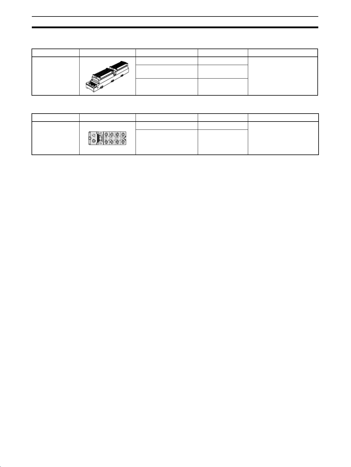
1-2-1 General-purpose Slaves
Name Appearance I/O points Model number Remarks
Screw-less Clamp
Terminal with Transistors
32 input points (PNP) ERT1-ID32SLH-1 With detection function
16 input points/16 output points (PNP)
32 input points (PNP) ERT1-OD32SLH-1
ERT1-MD32SLH-1
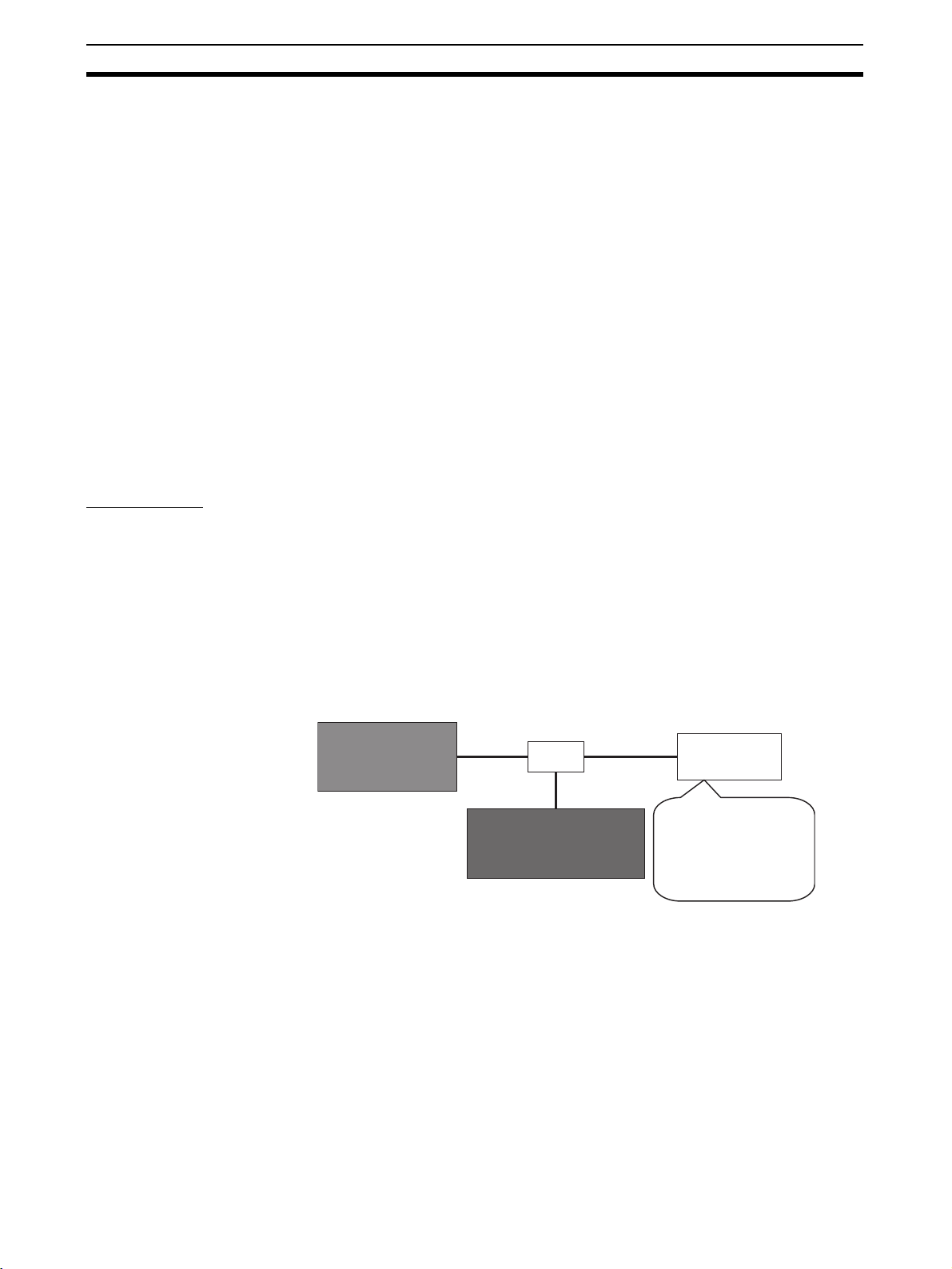
1-2-2 Environment-resistive Slaves
Name Appearance I/O points Model number Remarks
Environmentresistive Terminals
16 input points (PNP) ERT1-HD16CH-1 Waterproof, oil-proof, and
16 output points (PNP) ERT1-WD16CH-1
spatter-proof construction
(IP67).
Equipped with detection
functions.
4
Page 25

System Startup Procedure
This section describes the overall procedure that is used to set up and start an EtherNet/IP system.
2-1 Overview of System Startup Procedure . . . . . . . . . . . . . . . . . . . . . . . . . . . . . 6
2-1-1 Basic Procedure . . . . . . . . . . . . . . . . . . . . . . . . . . . . . . . . . . . . . . . . 6
2-1-2 Setting IP Addresses. . . . . . . . . . . . . . . . . . . . . . . . . . . . . . . . . . . . . 8
2-1-3 Setting Tag Data Links . . . . . . . . . . . . . . . . . . . . . . . . . . . . . . . . . . . 9
2-1-4 Checking Operation . . . . . . . . . . . . . . . . . . . . . . . . . . . . . . . . . . . . . 11
2-1-5 Common Operating Procedures . . . . . . . . . . . . . . . . . . . . . . . . . . . . 12
2-1-6 Edit Connection Dialog Boxes . . . . . . . . . . . . . . . . . . . . . . . . . . . . . 34
2-2 Recommended Network Devices . . . . . . . . . . . . . . . . . . . . . . . . . . . . . . . . . . 37
2-2-1 Network Devices Manufactured by OMRON . . . . . . . . . . . . . . . . . 37
SECTION 2
5
Page 26
Overview of System Startup Procedure Section 2-1
2-1 Overview of System Startup Procedure
This section explains the overall procedure for using EtherNet/IP using a basic
example.
2-1-1 Basic Procedure
The basic procedure is given below. For details on settings and connections,
refer to the Operation Manual for the Master Unit, as well as the detailed
descriptions of individual Slaves.
■ Preparations
↓
■ Setting IP addresses
↓
■ Setting tag data links
↓
■ Checking operation
Preparations The following Units are used in this example.
EtherNet/IP Unit: CJ2H-CPU68-EIP
EtherNet/IP Slave Unit: ERT1-WD16CH-1
If tag data links are used, a switching hub must be installed. Select a switching hub that is capable of handling the type of communications being performed over the network.
Refer to 2-2 Recommended Network Devices.
The network devices and IP addresses that are used in the following procedures are shown below. All of the devices have a subnet mask of
255.255.255.0, and are set to the same network address.
OMRON CJ2HCPU68-EIP
EtherNet/IP Unit
(192.168.0.10)
Ethernet
cable
HUB
OMRON ERT1-WD16CH-1
Sixteen-output Slave Unit
Ethernet
cable
Ethernet
cable
Personal
computer
(192.168.0.100)
Personal computer on
which the Network
Configurator is
installed. Used to
make settings.
1. Network Configurator Initial Settings
Start the Network Configurator. Refer to Common Procedure 2. Starting the
Network Configurator.
Install the EDS files for the Slave Units. Refer to Common Procedure 3.
Installing the EDS Files.
2. Connecting the Slave Units
• Connecting the Ethernet Cable
Align the polarizing key, insert the connector on the Ethernet cable into
the Ethernet connector on the Slave Unit, and then tighten the lock nut.
6
Page 27
Overview of System Startup Procedure Section 2-1
• Connecting the Power Cable
Align the polarizing key, insert the connector of the power cable into the
power connector on the Slave Unit, and then tighten the lock nut. The
Slave Unit requires a 24-VDC power supply.
Note Do not turn ON the power to the Slave Unit yet.
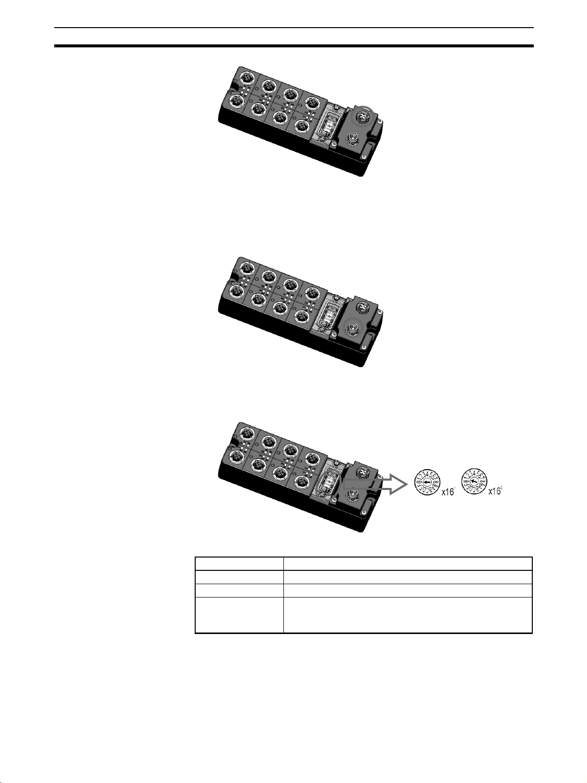
• Rotary Switches
The relationship between the rotary switches on the Slave Unit and the IP
address is shown below.
Rotary switches IP address
00 BOOTP/software setting
01 to FE 192.168.250.n (n = 01 to FE hex: Rotary switch setting)
FF Restores the default setting.
(To restore the default setting, set the switches to FF hex,
cycle the power supply, and then set the switches to 00 hex.)
• Slave Default Settings
The default settings are as follows:
• Rotary switches: 00
• IP address: BOOTP
7
Page 28
Overview of System Startup Procedure Section 2-1
The IP address will be as follows when the rotary switches are set to 01 to
FE hex: 192.168.250.n (n = Decimal equivalent of value set on rotary
switches).
2-1-2 Setting IP Addresses
Set the slave IP address for each device. Set same network address for all
devices. The following shows an example of setting the IP addresses for use
in this procedure.
IP address
Subnet mask
Default gateway
Personal computer
192.168.0.100
255.255.255.0
Not set. Not set (0.0.0.0).
This part is set to the same value for
all devices.
EtherNet/IP Unit
192.168.0.10
255.255.255.0
EtherNet/IP Slave Unit
192.168.0.20
255.255.255.0
Not set.
Note After an IP address has been set, check whether the setting is cor-
rect by connecting the personal computer to the device, and then
entering “ping IP_address” from the personal computer. For the
EtherNet/IP Unit in the above example, enter “ping 192.168.0.10.”
The setting is correct if the following is returned.
Pinging 192.168.0.10 with 32 bytes of data:
Reply from 192.168.0.10: bytes=32 time=1ms TTL=255
Reply from 192.168.0.10: bytes=32 time=1ms TTL=255
Reply from 192.168.0.10: bytes=32 time<1ms TTL=255
Reply from 192.168.0.10: bytes=32 time<1ms TTL=255
Ping statistics for 192.168.0.10:
Packets: Sent = 4, Received = 4, Lost = 0 (0% loss),
Approximate round trip times in milli-seconds:
Minimum = 0ms, Maximum = 1ms, Average = 0ms
1,2,3... 1. Setting the IP Address of the Personal Computer
Set the IP address of the personal computer.
2. Setting the IP Address of the EtherNet/IP Unit
Set the IP address of the EtherNet/IP Unit. Refer to Common Procedure 6-
1. Address Setting for OMRON EtherNet/IP Units.
3. Setting the IP Addresses of the EtherNet/IP Slave Units
The IP address of an EtherNet/IP Slave Unit can be set using any of the
following three methods.
• Setting the IP address with a CIP message (Network Configurator)
• Setting the IP address with a BOOTP/DHCP server
• Setting the IP address with the rotary switches
■ Setting the IP Address with a CIP Message (Network Configurator)
The Network Configurator can be used to set IP addresses.
This method involves first using the rotary switches to set an initial IP address,
and then using the Network Configurator to set the desired IP address.
8
Page 29

Overview of System Startup Procedure Section 2-1
1,2,3... 1. Set the rotary switches (hexadecimal) on the Slave Unit to the initial IP ad-
dress.
The initial IP address will be 192.168.250.n (where n is the value to which
the rotary switches are set).
(If the rotary switches are set to 0A, the initial IP address will be
192.168.250.10.)
After setting the rotary switches, turn ON the power to the Slave Unit.
2. Check to be sure the initial IP address is correct.
3. Step III: Set the IP address using the Network Configurator.
Refer to Common Procedure 4. Connecting the Network Configurator On-
line and Common Procedure 6-2 Setting IP Addresses Using the Network
Configurator.
4. Set the rotary switches to 00 and then turning the cycle the power supply.
Operation will start with the new IP address.
■ Setting the IP Address with the BOOTP/DHCP Server
This method involves first using the rotary switches to set an initial IP address,
and then using the Network Configurator and the BOOTP/DHCP server to set
the desired IP addresses.
1,2,3... 1. Set the rotary switches to 00.
2. Set the IP address using the BOOTP/DHCP server.
Refer to Common Procedure 6-3. Setting IP Address Using the BOOTP
Server.
■ Setting the IP Address with the Rotary Switches
1,2,3... 1. Set the rotary switches (hexadecimal) on the Slave Unit to the desired IP
address.
The initial IP address will be 192.168.250.n (where n is the value to which
the rotary switches are set).
(If the rotary switches are set to 0A, the initial IP address will be
192.168.250.10.)
After setting the rotary switches, turn ON the power to the Slave Unit.
2-1-3 Setting Tag Data Links
Set data links using the OMRON Network Configurator.
■ Connecting to the Network
Refer to Common Procedure 4. Connecting the Network Online.
■ Uploading the Network Configuration
Refer to Common Procedure 5. Uploading the Current Network Configuration.
■ Setting Tag Data Links
Set the tag data links.
1,2,3... 1. Refer to Common Procedure 7-2. Registering a Tag Set with the PLC.
Create a 2-byte output tag.
2. Set a connection.
The subsequent steps are performed using the CJ2B-EIP21 Edit Device
Parameters Dialog Box.
9
Page 30
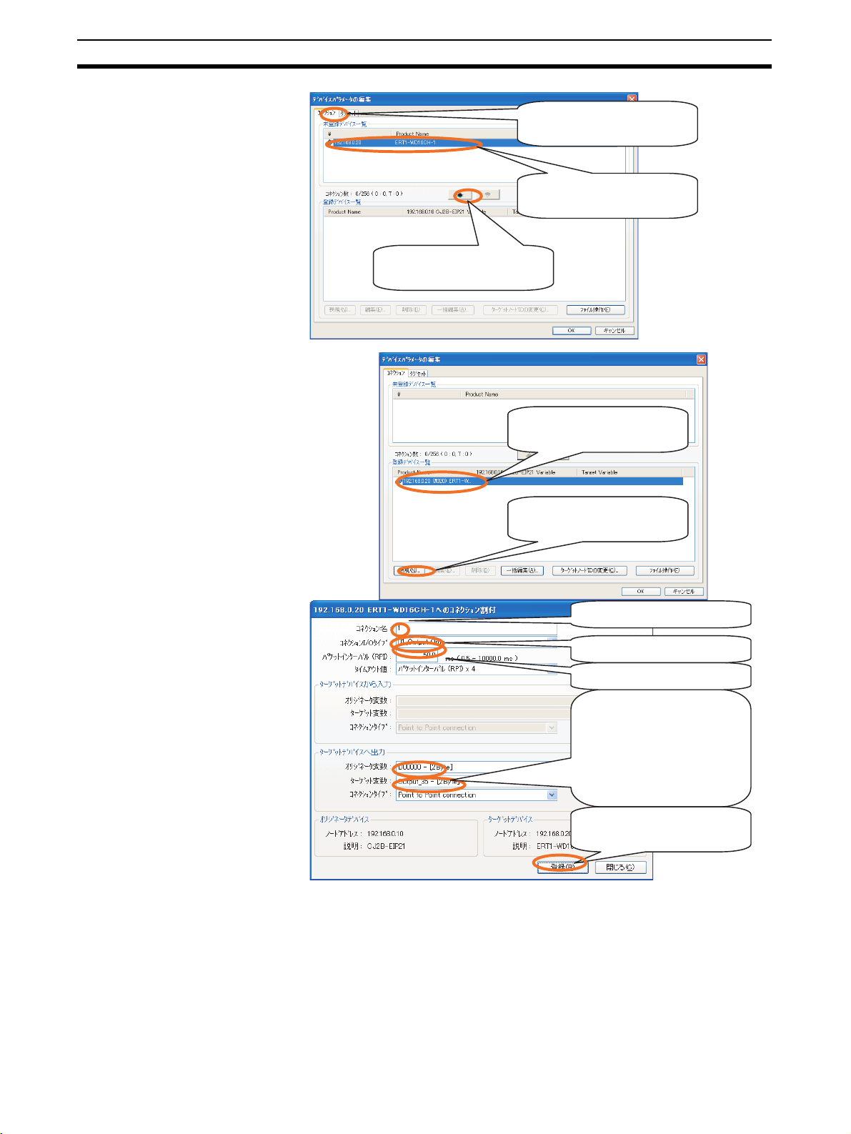
Overview of System Startup Procedure Section 2-1
1. Click the Connections Tab.
2. Select the device to which a link
is to be established.
3. Click this button to register the
device to which a link is to be
established.
1. The ERT1-WD16CH-1 has been
registered as the device to which
a link is established.
2. Click the New Button to create
the connection.
1. Input a name for the connection.
2. Select 01_Output Only.
3. Input the RPI.
4. Select the consume and
5. Click the Register Button to
produce variables. Select
Output_35 as the produce
variable. Make sure that the
sizes of the variables are the
same.
register the connection.
The Edit Connection Dialog Box will not be closed. If no further connections are to be set, click the Close Button.
The connection will appear in the list of registered devices.
10
Page 31

Overview of System Startup Procedure Section 2-1
Click the OK Button to enable the
settings.
After a connection has been set, a window like the one shown below will
be displayed.
When the above window is displayed, setting the connection has been
completed.
3. Write the connection settings to the devices.
Refer to Common Procedure 7-4. Downloading Connection Settings to De-
vices.
2-1-4 Checking Operation
Make sure that tag data link is operating normally.
■ EtherNet/IP Unit
Check the display and indicators on the EtherNet/IP Unit. The following status
indicates that tag data link is operating normally.
• MS indicator: Lit green.
• NS indicator: Lit green.
• 7-segment display: Shows the rightmost digits of the EtherNet/IP Unit
node address in hexadecimal (0A would be displayed for address
192.168.0.10).
This mark will be displayed when
a connection has been set.
■ EtherNet/IP Slave Unit
Check the indicators on the Slave Unit. The following status indicates that tag
data link is operating normally.
• MS indicator: Lit green.
11
Page 32

Overview of System Startup Procedure Section 2-1
• NS indicator: Lit green.
2-1-5 Common Operating Procedures
This section provides the procedures that are used to set up and start an EtherNet/IP Unit.
Common Procedure 1. Configuration Used in Common Procedures
Common Procedure 2. Starting the Network Configurator
Common Procedure 3. Installing EDS Files
Common Procedure 4. Connecting the Network Online
Common Procedure 5. Uploading the Current Network Configuration
Common Procedure 6. Setting IP Addresses
Common Procedure 6-1. Setting IP Addresses for OMRON EtherNet/IP
Units
Common Procedure 6-2. Setting IP Addresses Using the Network Config-
urator
Common Procedure 6-3. Setting IP Addresses Using the BOOTP Server
Common Procedure 6-3-1. Enabling BOOTP from the Network Con-
figurator
Common Procedure 6-3-2. Setting IP Addresses Using the BOOTP
Server
Common Procedure 7. Setting Tag Data Links
Common Procedure 7-1. Setting the I/O Sizes of Devices
Common Procedure 7-2. Registering Tag Sets in the PLC
Common Procedure 7-2-1. Setting Tag Sets Using Physical Address-
es
Common Procedure 7-2-2. Setting a Tag Using a Symbol
Common Procedure 7-2-3. Combining Tags Into a Single Tag Set
Common Procedure 7-3.Setting Connections
Common Procedure 7-4.Downloading Connection Settings to Devices
Common Procedure 7-4-1. Downloading the Same Connection Set-
tings to All of the Devices in the Network
Configurator
Common Procedure 7-4-2. Downloading Connection Settings to Se-
lected Devices
Common Procedure 1. Configuration Used in Common Procedures
The following figure shows the configuration and IP addresses used in the
common procedures.
The subnet mask is set to 255.255.255.0 and the same network address is
set for all devices.
OMRON
EtherNet/IP Unit
(192.168.0.10)
Ethernet
cable
EtherNet/IP device
(192.168.0.20)
HUB
Ethernet
cable
Ethernet
cable
Personal
computer
(192.168.0.100)
12
Page 33

Overview of System Startup Procedure Section 2-1
Common Procedure 2. Starting the Network Configurator
Select All Programs − OMRON − CX-One − Network Configurator for Eth-
−
erNet/IP
Network Configurator from the Windows Start Menu. The Net-
work Configurator will start.
The following window will be displayed.
Common Procedure 3. Installing EDS Files
EDS is an acronym for Electronic Data Sheet. An EDS file contains network
device information. The OVDA requires that every EtherNet/IP device has an
EDS file. Contact the manufacturer of the device to obtain an EDS file. Use
the following procedure to install the EDS file.
1,2,3... 1. Using the Network Configurator, select EDS File
EDS file for the device to be connected.
2. Select the EDS file of the device to be installed, and then click the Open
Button
Select the EDS file for
the device to be added.
3. If there is also a device icon to be installed, click the Yes Button to start the
installation. If there is no icon, click the No Button.
−
Install to install the
If there is no icon, click
the No Button.
13
Page 34

Overview of System Startup Procedure Section 2-1
When the EDS file has been installed, the device will have been added as
shown in the following window.
Make sure that the device has
been added to the
EtherNet/IP Hardware list.
Common Procedure 4. Connecting the Network Online
This section describes how to connect the Network Configurator online
through Ethernet (i.e., through the EtherNet/IP Unit).
Note Make sure that each device is connected via an Ethernet cable as
described in Common Procedure 1, and that each device has the
same network address.
1,2,3... 1. Select the interface for the Network Configurator (select online connection
from the personal computer).
−
Select Options
Select Interface − Ethernet I/F.
Select Options - Select
Interface - Ethernet I/F.
A checkmark will appear
by Ethernet I/F
2. Establish an online connection.
−
Select Network
Connect.
Select Network - Connect
to establish a connection.
Select the Ethernet interface of the personal computer being used.
When the personal computer has
more than one Ethernet interfaces,
select the interface to use.
14
In the following diagram, TCP 2 indicates the EtherNet/IP network. Click
the OK Button.
Page 35

Overview of System Startup Procedure Section 2-1
Click the OK Button.
After the connection has been established, the following window will be
displayed.
Make sure a blue mark
is displayed for
EtherNet/IP_1.
Make sure that online
status is indicated.
Common Procedure 5. Uploading the Current Network Configuration
This section explains the procedure for uploading the configuration information from the devices connected to the EtherNet/IP network.
−
Select Network
network.
If the IP address of a connected device does not appear in the IP addresses
displayed in this dialog box, click the Add Button and register that IP address.
There may also be instances where the IP address of an unconnected device
is displayed. If that occurs, just click the OK Button.
Upload to start uploading the configuration of the current
Click the Yes Button.
15
Page 36

Overview of System Startup Procedure Section 2-1
The IP addresses of devices that
were connected when the Network
Configurator was started will be
displayed. If the IP addresses of all
currently connected devices are
displayed here, then simply click the
OK Button. There is no need to
change the check boxes.
If the IP address of a currently
connected device is not displayed,
click the Add Button to add that IP
address.
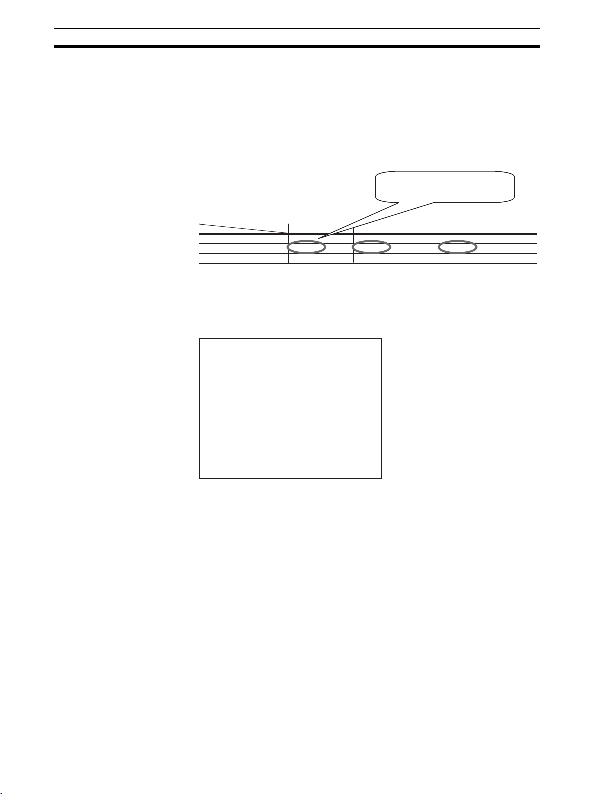
After the configuration information has been uploaded, the following window
will be displayed. Check whether all of the connected EtherNet/IP devices are
displayed in the window.
Check the IP addresses in
the top row, and the model
numbers in the bottom row.
Common Procedure 6. Setting IP Addresses
This section explains three ways of setting IP addresses:
• Setting IP addresses for OMRON EtherNet/IP Units
• Setting the IP addresses using the Network Configurator (CIP messages)
• Setting the IP addresses using the BOOTP server
Common Procedure 6-1. Setting IP Addresses for OMRON EtherNet/IP Units
Use the following procedure to set the IP address of the OMRON EtherNet/IP
Unit (CJ1W-EIP21, CS1W-EIP21, or CJ2B-EIP21).
1,2,3... 1. Check the current IP address of the EtherNet/IP Unit.
Use the 7-segment display to check the IP address.
7-segment display
When the power is turned ON or the Unit is restarted, all of the segments of
the display will flash twice, and then the display will flash “IP” twice. Then, the
IP address set for the EtherNet/IP Unit will be displayed once only, flowing
from the right to the left.
16
Page 37

Overview of System Startup Procedure Section 2-1
Example 1: Displaying IP Address 192.168.250.10
The IP address is displayed in decimal, flowing from right to left.
2. Set the address of the EtherNet/IP Unit
Refer to Common Procedure 4. Connecting the Network Online. For de-
tails on setting IP addresses using the Network Configurator (CIP messages), refer to Common Procedure 6-2. When setting the IP addresses using
a BOOTP server, refer to Common Procedure 6-3.
3. Operation after Completing the Setting
If an F3 error occurs after setting the IP address, set the node switches on
the front of the EtherNet/IP Unit to the hexadecimal equivalent of the loworder digit of the IP address.
Common Procedure 6-2. Setting IP Addresses Using the Network Configurator
−
1,2,3... 1. Select Tools
Configuration Dialog Box.
2. Input the IP address of the device that is to be changed in the Ta r g e t I P
Address Box.
Click the Get from the Device Button to get the current settings.
Change the IP address or subnet mask, and then click the Set to the De-
vice Button. The new settings will be written to the device.
Setup TCP/IP Configuration to open the Setup TCP/IP
17
Page 38

Overview of System Startup Procedure Section 2-1
Input the IP address of
the device to be set.
Input the new IP address
or subnet mask.
Finally, click the Set to
the Device Button.
When the settings have been completed, the following message will be displayed.
Note If the following message is displayed, perform the steps given be-
low.
• Check whether the device supports IP address setting using the Network Configurator (IP address setting with CIP messages). If this
method is not supported, use a different method to set the IP address.
• Repeat the above setting procedure from the very beginning. The IP
address that was set for the device with the Network Configurator using a CIP message may not be enabled.
Common Procedure 6-3. Setting IP Addresses Using the BOOTP Server
Common Procedure 6-3-1. Enabling BOOTP from the Network
Configurator
−
1,2,3... 1. Select Tools
Setup TCP/IP Configuration to open the Setup TCP/IP
Configuration Dialog Box.
2. Input the current IP address of the device to be set in Target IP Address
Box.
In the New Configuration Area, select the Set the IP address via BOOTP
server Option, and then click the Set to the Device Button.
18
Page 39

Overview of System Startup Procedure Section 2-1
Input the IP address of
the device to be set.
Select Set the IP
address via BOOTP
server.
Click the Set to the
Device Button.
When the settings have been completed, the following message will be displayed.
Note If a message like the one shown below is displayed, perform the
steps given below.
Repeat the above setting procedure from the very beginning.
Common Procedure 6-3-2. IP Address Setting Using the BOOTP Server
This procedure uses the BOOTP_DHCP Server distributed by Rockwell Automation, Inc., as the BOOTP server. (This server can be downloaded from
http://www.ab.com/networks/bootp.html.)
1,2,3... 1. Select All Programs
the Windows Start Button to start the BOOTP server.
−
Rockwell Software − BOOTP-DHCP Server from
2. Connect those devices in either BOOTP or DHCP mode to the computer.
For details on how to set BOOTP or DHCP mode, refer to the manual for
each device.
19
Page 40

Overview of System Startup Procedure Section 2-1
When either BOOTP
mode or DHCP mode is
enabled for a connected
device, the MAC
address of the
Click the New Button.
3. Adding to the Relation List
Check the MAC address of the device to be added. Click the New Button
in the dialog box. A table is created listing MAC addresses and the corresponding IP addresses assigned to the devices.
requesting device will be
displayed here.
Input the MAC address.
Use a colon as the
delimiter.
Input the IP address.
After the new entry has been registered, it will be added to the list as shown
in the following diagram.
The address table is
added to the list.
When the IP address is
set using the BOOTP
server, the IP address
set for the MAC address
of the device is
displayed here.
20
This completes setting the IP address using the BOOTP server.
Note To change the setting so that the IP address is no longer set using
the BOOTP server, click the Disable BOOTP/DHCP Button. Sub-
sequently, even if the device is turned OFF and then ON again, the
IP address will not be set by the BOOTP server, and the device will
start with the previous IP address.
Page 41

Overview of System Startup Procedure Section 2-1
Common Procedure 7. Setting Tag Data Links
Common Procedure 7-1. Setting the I/O Sizes of Devices
Depending on the device, the I/O sizes may either be fixed or symbol. For
details on setting the device I/O sizes, refer to the manual for each device.
Common Procedure 7-2. Registering Tag Sets in the PLC.
Set the tag set in the PLC that is to function as the master. The tag set size
must be the same as the device I/O size of the communications partner.
Two methods of registering a tag set are provided: using the physical
addresses (Common Procedure 7-2-1), and using symbols (Common Proce-
dure 7-2-2)
Note The following diagram illustrates the relationship between tag sets
and tags.
Tag set
Tag 1
Tag 2
.
.
.
Common Procedure 7-2-1. Setting Tag Sets Using Physical Addresses
Use the following procedure to directly set physical addresses (e.g., in the
CIO or DM Area) in the CPU Unit a PLC in the tag set.
• A tag set contains one or more tags.
• The size of a tag set will be equal to the total of
the sizes of all of the tags in the tag set.
1,2,3... 1. Double-click the icon for the EtherNet/IP Unit (CJ2B-EIP21 in the figure).
The Edit Device Parameters Dialog Box for the EtherNet/IP Unit will be displayed.
Click the Tag Sets Tab.
2. Register the tags.
Set the input tags first. An input tag receives the data that is output from
the target.
Click the In-Consume Tab, and then click the Edit Tags Button.
21
Page 42

Overview of System Startup Procedure Section 2-1
Make sure that the InConsume Tab.
Click the Edit Tags
Button.
The Edit Tags Dialog Box will be displayed. Click the New Button.
Click the New Button.
Set the tag name and size. Set the size in increments of 2 bytes. The input
size must be the same as the output size of the target device. Click the
Register Button to register the tag.
The tag name depends on the physical address, as shown below. *Addresses that do not appear in the following table cannot be specified. Also,
the number of EM banks varies with the CPU Unit of the PLC.
Physical address Address (text to input in
Name Field)
CIO Area 0000 to 6143
Holding Area H000 to H511
Work Area W000 to W511
DM Area D00000 to D32767
EM Area Bank 0 E0_00000 to E0_32767
to to
Bank 24 E18_00000 to E18_32767
22
The Edit Tag Dialog Box shown below will be displayed. When you are finished registering tags, click the Close Button.
Page 43

Overview of System Startup Procedure Section 2-1
A tag will be registered.
A new 2-byte tag
called D00000 has
been added.
In the same way, set the output tag.
Click the Out-
Produce Tab.
Click the New Button
and set the tag in the
same way.
A tag called D01000 is
added.
When you are finished,
click the OK Button.
3. Register the tag set.
A message will be displayed asking if the registered tags are to be registered as a tag set. Click the Yes Button.
23
Page 44

Overview of System Startup Procedure Section 2-1
The tags are to be
registered as a tag
set, so click the Yes
Button.
A tag set with the
same name as the tag
is registered.
Check both the input
and output tags.
Common Procedure 7-2-2. Setting Tags Using Symbols
Use the following procedure to use CX-Programmer to create a symbol, which
can then loaded as a tag by the Network Configurator.
1,2,3... 1. Register the symbol with the CX-Programmer.
Start the CX-Programmer specifying the model number of the CPU Unit
you are using.
2. Register the symbol.
Click Symbol Table under
the PLC icon.
Click Insert Symbol.
Input the symbol name.
Select the data type.
Input the address to store
the symbol. In this example,
automatic allocation is set,
so leave this box empty.
24
To register the symbols as an
array, click the Advanced Button
and enter the number of array
elements.
Select the Network Symbol
Check Box and select either
the Input or Output Option.
Click the OK Button.
Page 45

Overview of System Startup Procedure Section 2-1
When a network symbol has been created, a window like the one shown
below will be displayed.
The created network symbol
has been registered.
For example, the symbols shown below are created.
3. Import the symbol to the Network Configurator.
Start the Network Configurator while CX-Programmer is running.
Double-click the icon for the EtherNet/IP Unit (CJ2B-EIP21 in the diagram).
The Edit Device Parameters Dialog Box for the EtherNet/IP Unit will be displayed.
25
Page 46

Overview of System Startup Procedure Section 2-1
Click the Tag Sets Tab.
Make sure that the InConsume Tab Page is
displayed.
Click the Import Button.
A message like the one shown below will be displayed. Click the OK Button.
A message like the one shown below will be displayed. Click the Yes Button.
A dialog box like the one shown below will be displayed. Each network
symbol has been registered as a tag set.
26
Page 47

Overview of System Startup Procedure Section 2-1
Each symbol has been
registered as a tag set.
Common Procedure 7-2-3. Combining Multiple Tags Into a Single Tag Set
The procedure shows how to combine more than one tag into a tag set.
Delete the tag sets without deleting the tags.
Select the tag sets to be
deleted.
Click the Delete Button.
A warning message like the one shown below will be displayed. When only
the tag sets are to be deleted, click the No Button.
Also delete the output tag sets.
27
Page 48

Overview of System Startup Procedure Section 2-1
Click the Out-Product Tab.
Select the tag sets to be
deleted.
Click the Delete Button.
The tag sets will be deleted.
Create a new tag set into which the tags will be combined.
Click the New Button.
28
Page 49

Overview of System Startup Procedure Section 2-1
Select tags to be added to
the tag set.
Click here to register the
selected tags in the tag list.
Added to the tag list.
Input a name for the tag
set.
Click the OK Button.
A message will appear asking whether another tag set is to be created. If no
other tag sets are to be created, click the Close Button.
Note When tag data links operate, data is sent in the order in which the
tags are registered in the tag set. When combining tags into a tag
set, pay attention to the order and size of the tags.
Tag set A
Tag 1
Tag 2
Tag set B
Tag 3
Tag 4
The new tag set has been registered.
The new tag has been
registered. When the
icon is double-clicked,
the tags in the tag set
will be displayed.
Click the Out-Produce
Tab, and register the
new tags in an output
tag set.
Also register the output tag set.
29
Page 50

Overview of System Startup Procedure Section 2-1
A new output tag set is
registered.
This completes the combining tags into a tag set.
Common Procedure 7-3. Setting Connections
This procedure is performed using the CJ2B-EIP21 Edit Device Parameters
Dialog Box.
1. Click the Connection Tab.
3. Click this button to register the
selected device as the link
destination.
1. The SMC EX250-SEN1 has been
registered as the link destination.
2. Click the New Button to create
the connection.
2. Select the link destination (SMC
EX250-SEN1 in this example).
30
Page 51

Overview of System Startup Procedure Section 2-1
1. Input a name for the connection.
2. Input the RPI.
3. Select the consume and produce
variables. Make sure that the
sizes are the same.
4. Also register the output variables.
5. To register the connection, click
the Register Button.
The dialog box for making connections will not close. If no more connections
are to be created, click the Close Button.
The new connection will be displayed in the Registered Device List.
Click the OK Button to enable
the settings.
After the connection settings have been made, a window like the one shown
below will be displayed.
31
Page 52

Overview of System Startup Procedure Section 2-1
When a connection has been set,
a mark like this will be displayed.
This completes the connection settings.
Common Procedure 7-4. Downloading the Connection Settings to a Device.
This section explains how the connection settings made with the Network
Configurator are downloaded to the devices and enabled.
Either of the following two methods can be used.
• Downloading the same connection settings to all devices in the Network
Configurator
• Downloading connection settings only to selected devices
Common Procedure 7-4-1 Downloading the Same Connection Settings
to all Devices in the Network Configurator
Use the following procedure to download the same connection settings to all
of the devices displayed in the window.
Click Network - Download.
Click the Yes Button.
Depending on the status of the connected PLC, a window like the one shown
below may be displayed.
32
Page 53

Overview of System Startup Procedure Section 2-1
Click the Download after
changed to Program
mode Button.
Click the Yes Button.
After the connection settings have been downloaded, a message like the one
shown below will be displayed. Click the OK Button.
Common Procedure 7-4-2 Downloading Connection Settings to
Selected Devices
From the devices displayed in the window, select those to which the connection settings are to be downloaded.
Select devices from among those displayed in the window. In the following
example, the device on the left and device on the right are selected.
−
Right-click and select Parameter
Download.
33
Page 54

Overview of System Startup Procedure Section 2-1
Click the Yes Button.
Depending on the status of the connected PLC, a window like the one shown
below may be displayed.
Click the Download after
changed to Program
mode Button.
Click the Yes Button.
After the connection settings have been downloaded, a message like the one
shown below will be displayed. Click the OK Button.
2-1-6 Edit Connection Dialog Boxes
The following figures show examples of connection settings for various EtherNet/IP Slave Units.
34
Page 55

Overview of System Startup Procedure Section 2-1
• ERT1-WD16CH-1
1. Input a name for the connection.
2. Select 01_Output Only.
3. Input the RPI.
4. Select the consume and
produce variables. For the
produce variable, select
Output_35. Make sure that the
sizes of the variables are the
same.
• ERT1-HD16CH-1
1. Input a name for the connection.
•ERT1-ID32SLH-1
2. Select 01_Output Only.
3. Input the RPI.
4.Select the consume and
produce variables. For the
produce variable, select
Input_5. Make sure that the
sizes of the variables are the
same.
1.Input a name for the connection.
2. Select 01_Output Only.
3.Input the RPI.
4.Select the consume and
produce variables. For the
produce variable, select
Input_6. Make sure that the
sizes of the variables are the
same.
35
Page 56

Overview of System Startup Procedure Section 2-1
• ERT1-OD32SLH-1
1.Input a name for the connection.
2.Select 01_Output Only.
3.Input the RPI.
4.Select the consume and
produce variables. For the
produce variable, select
Input_36. Make sure that the
sizes of the variables are the
same.
• ERT1-MD32SLH-1
1.Input a name for the connection.
2. Select 01_Output Only.
1.Input a name for the connection.
2. Select 01_Output Only.
3.Input the RPI.
4.Select the consume and
produce variables. For the
produce variable, select
Input_6. Make sure that the
sizes of the variables are the
same.
3.Input the RPI.
4.Select the consume and
5.Select the consume and
produce variables. For the
produce variable, select
Input_35. Make sure that the
sizes of the variables are the
same.
produce variables. For the
produce variable, select
Output_5. Make sure that the
sizes of the variables are the
same.
36
Page 57

Recommended Network Devices Section 2-2
2-2 Recommended Network Devices
The following table shows the devices recommended for use with the EtherNet/IP.
Part Maker Model number Inquires
Switching
Hub
Twisted-pair
cable
Connectors
(Modular
plug)
Boots Tsuko Company MK boot (IV) LB Tsuko Company Japan Headquar-
Cisco Systems, Inc. Consult the manufacturer. Cisco Systems, Inc. Main Corpo-
rate HQ
Contec USA, Inc. Consult the manufacturer. CONTEC USA Inc.
Phoenix Contact Consult the manufacturer. Phoenix Contact USA Customer
Service
100BASE-TX
Fujikura F-LINK-E 0.5mm × 4P Fujikura America, Inc.
EtherNet/IP compliant cable ---
STP Plug
Panduit Corporation MPS588 Panduit Corporation US Headquar-
ters
ters
Note (1) Always use a switching hub when using tag data links in the network.
(2) If a repeater hub is used for EtherNet/IP tag data links (cyclic communi-
cations), the network’s communications load will increase, data collisions
will occur frequently, and stable communications will be impossible.
2-2-1 Network Devices Manufactured by OMRON
The following network devices are manufactured by OMRON for EtherNet/IP
networks.
Name Model Function Number of
Switching Hub W4S1-03B Packet priority control (QoS):
W4S1-05B 5 None
W4S1-05C 5 Provided.
W4S1-10B 10 None
W4S1-10C 10 Provided.
EtherNet/IP control data priority
Failure detection: Broadcast
storm, LSI error detection, 10/
100Base-TX, Auto-Negotiation
ports
3None
Error detection
output
37
Page 58

Recommended Network Devices Section 2-2
38
Page 59

Basic Specifications of Slave Units
This section provide the basic specifications of the EtherNet/IP Slave Units
3-1 Basic Specifications of Slave Units . . . . . . . . . . . . . . . . . . . . . . . . . . . . . . . . 40
3-1-1 Communications Specifications . . . . . . . . . . . . . . . . . . . . . . . . . . . . 40
3-1-2 Performance Specifications . . . . . . . . . . . . . . . . . . . . . . . . . . . . . . . 40
3-1-3 Communications Indicators . . . . . . . . . . . . . . . . . . . . . . . . . . . . . . . 40
SECTION 3
39
Page 60

Basic Specifications of Slave Units Section 3-1
3-1 Basic Specifications of Slave Units
This section gives the specifications that are the same for all Slave Units. For
specifications that vary with the Slave Unit, refer to the section for each Slave
Unit.
3-1-1 Communications Specifications
Item Specifications
Communications protocol EtherNet/IP
Typ e 100Base-TX (See note.)
Transfer
specifications
Note If tag data links are being used, use 100Base-TX.
Media access method CSMA/CD
Modulation method Baseband
Transmission paths Star form
Baud rate 100 Mbit/s (100Base-TX)
Transmission media Shielded twisted-pair (STP) cable
Categories: 100 Ω at 5, 5e or higher
Transmission distance 100 m (distance between hub and node)
Number of cascade
connections
There is no limitation when a switching hub is
used.
3-1-2 Performance Specifications
Item Specifications
Unit power supply voltage 20.4 to 25 VDC
I/O power supply voltage 20.4 to 26.4 VDC (24 VDC, −15 to +10%)
Noise immunity Power lines: Conforms to IEC 61000-4-4 2 kV.
Vibration resistance 10 to 60 Hz with 0.35-mm amplitude 10 times
Shock resistance
Insulation resistance 20 MΩ min. (at 250 VDC) between current-
Ambient temperature −10 to 55°C
Ambient humidity 25% to 85% (with no condensation)
Storage temperature −25 to 65°C
Mounting Mounted on 35-mm DIN Track, or secured
Conforms to the following EC Directives:
IEC 61000-4-2
IEC 61000-4-3
IEC 61000-4-5
IEC 61000-4-6
each up, down, right, and left
60 to 150 Hz, 50 m/s
Maximum acceleration of 150 m/s
each up, down, right, and left
carrying circuits and non-current-carrying circuits
with M5 screws (depending on model)
2
2
3 times
3-1-3 Communications Indicators
The communications indicators have the following meanings.
MS (Module Status): Indicates the status of the node with a two-color LED
(green/red).
40
Page 61

Basic Specifications of Slave Units Section 3-1
NS (Network Status): Indicates the status of communications with a two-color
LED (green/red).
Name Indicator status Node/communications
Meaning
status
MS Lit green. Normal status The Unit is operating normally.
Lit red. Fatal error A hardware error has occurred in the Unit. The watchdog
Flashing red. Non-fatal error There is an error in the switch settings.
timer has timed-out.
Not lit. Power OFF or Startup The power supply is OFF, the Unit is being reset, or the Unit
is being initialized.
NS Lit green. Online and participating Tag data link communications have been established and
Flashing
green.
Lit red. Fatal communications
Flashing red. Non-fatal communications
Online but not participating
error
error
normal communications are in progress.
Normal communications are in progress, but tag data link
communications have not been established.
The address is set out of range.
The same address has been set for more than one node.
Communications has timed out.
Not lit. Power OFF or offline The power supply is OFF or the cable is not connected.
Note When flashing, indicators are lit for 0.5 s and not lit for 0.5 s.
41
Page 62

Basic Specifications of Slave Units Section 3-1
42
Page 63

Digital I/O Slave Units
This section describes the Digital I/O Slave Units for EtherNet/IP.
4-1 Status Areas. . . . . . . . . . . . . . . . . . . . . . . . . . . . . . . . . . . . . . . . . . . . . . . . . . . 44
4-1-1 Generic Status Area . . . . . . . . . . . . . . . . . . . . . . . . . . . . . . . . . . . . . 44
4-1-2 I/O Status Area . . . . . . . . . . . . . . . . . . . . . . . . . . . . . . . . . . . . . . . . . 45
4-2 Screw-less Clamp Terminals . . . . . . . . . . . . . . . . . . . . . . . . . . . . . . . . . . . . . . 45
4-2-1 Wiring to a Screw-less Clamp Terminal Block . . . . . . . . . . . . . . . . 45
4-2-2 Thirty-two-point Input Units (with Screw-less clamps) . . . . . . . . . . 47
4-2-3 Thirty-two-point Output Units (with Screw-less Clamps) . . . . . . . . 50
4-2-4 Sixteen-point Input and Sixteen-point Output Units
(with Screw-less clamps) . . . . . . . . . . . . . . . . . . . . . . . . . . . . . . . . . 53
SECTION 4
43
Page 64

Status Areas Section 4-1
4-1 Status Areas
A Digital I/O Slave Unit has two internal status areas: the Generic Status Area
and the I/O Status Area. The status flags in these areas are turned ON and
OFF based on the threshold values set by the user for each function in that
Unit.
4-1-1 Generic Status Area
The Digital I/O Slave Unit's Generic Status Area contains the following 16 bits.
Bit Content Description
00 I/O Power Supply Status Flag 1
OFF: I/O power is ON
ON: I/O power is not ON.
01 I/O Power Supply Status Flag 2
OFF: I/O power is ON
ON: I/O power is not ON.
02 Reserved ---
03 Reserved ---
04 Power or Load Short-circuit Detection
Flag
OFF: Normal
ON: Short-circuit
05 Disconnection Flag
OFF: Connected
ON: Disconnected
06 Reserved ---
07 Reserved ---
08 EEPROM Data Error Flag
OFF: Normal
ON: Error occurred
09 Reserved ---
10 Reserved ---
11 Reserved ---
12 Reserved ---
13 Reserved ---
14 Reserved ---
15 Reserved ---
Turns ON when I/O power is not
being supplied to terminal block 1.
Turns ON when I/O power is not
being supplied to terminal block 2.
Turns ON when there is a short in the
power supply or load connection to
the connected devices, including wiring mistakes and connected device
failure.
Turns ON when the sensor power
supply is not connected or the load is
disconnected due to a wiring error,
failure in the connected device, etc.
Turns ON when there is an error in
the EEPROM data.
44
Page 65

Screw-less Clamp Terminals Section 4-2
4-1-2 I/O Status Area
The I/O Status Area for a Digital I/O Slave Unit consists of the following 8
bytes (64 bits). The I/O Status Area indicates the short-circuit and disconnection error status for each terminal.
Byte
offset
0 Power or Load Short-circuit Detection Flags for Terminal Block 1
1 Power or Load Short-circuit Detection Flags for Terminal Block 1
2 Power or Load Short-circuit Detection Flags for Terminal Block 2
3 Power or Load Short-circuit Detection Flags for Terminal Block 2
4 Disconnection Flags for Terminal Block 1
5 Disconnection Flags for Terminal Block 1
6 Disconnection Flags for Terminal Block 2
7 Disconnection Flags for Terminal Block 2
Bit 07 06 05 04 03 02 01 00
07 06 05 04 03 02 01 00
15 14 13 12 11 10 09 08
07 06 05 04 03 02 01 00
15 14 13 12 11 10 09 08
07 06 05 04 03 02 01 00
15 14 13 12 11 10 09 08
07 06 05 04 03 02 01 00
15 14 13 12 11 10 09 08
Data
4-2 Screw-less Clamp Terminals
The screw-less clamp terminal has a structure designed for clamping to a terminal block. It is a reduced-wiring, labor-saving Slave that can make wiring
easy by simply inserting ferrules (with sleeves). The Unit and terminal block
can be detached, making it possible to replace the Unit in the event of a failure
without removing the wiring.
A detection function is also provided to help quickly discover short-circuits and
disconnections for sensors or other devices.
4-2-1 Wiring to a Screw-less Clamp Terminal Block
Screw-less clamp terminals provide clamp-type terminal blocks that allow wiring without screws. When connecting a sensor or an external device, a ferrule
must be attached to the cable for the sensor or device. The following ferrules
are applicable.
Manufacturer Model
Phoenix Contact AI-0.5-10
AI-0.75-10
AI-1.5-10
AI-2.5-10
Nihon Weidmuller H 0.5/16 D
H 0.75/16 D
H 1.5/16 D
H 2.5/16 D
0.5 mm
0.75 mm
1.25 mm
2.0 mm
0.5 mm
0.75 mm
1.25 mm
2.0 mm
2
(AWG 20)
2
(AWG 18)
2
(AWG 16)
2
(AWG 14)
2
(AWG 20)
2
(AWG 18)
2
(AWG 16)
2
(AWG 15)
45
Page 66

Screw-less Clamp Terminals Section 4-2
r
Wiring to a Clamp Terminal Block
Insertion Insert the ferrule all the way to the end in any terminal hole.
Removal Pull out the power line while pressing down with a small flat-blade screwdriver
on the release button above the terminal hole.
Small flat-blade screwdrive
+
NC
V
V
+
V
+
V
+
V
+
V
+
V
+
7
0
8
0
2
0
3
0
4
0
5
0
6
0
Release button
1
2
3
4
Screwdriver Used to
You will need a screwdriver that is consistently thin for the entire length.
Remove Ferrules
0.5 mm max.
3.0 mm max.
Recommended Screwdriver Model
Model Manufacturer
SZF1 Phoenix Contact
Removing and Mounting a Clamp Terminal Block
Removal Use a flat-blade screwdriver to loosen the four screws on the top of the termi-
nal block, and then grasp the handles on both sides and remove the terminal
block.
Mounting Grasp the handles on both sides of the terminal block, and insert the terminal
block firmly in place. Then use a flat-blade screwdriver to tighten the four
screws on the top of the terminal block.
1
2
1
46
Four 2.6 x 6 standard screws
Grasp handles on both sides.
Pull out the terminal block.
Note Tighten the screws to a torque of 0.2 to 0.25 N·m.
Page 67

Screw-less Clamp Terminals Section 4-2
4-2-2 Thirty-two-point Input Units (with Screw-less clamps)
ERT1-ID32SLH-1
Input Specifications
Item Specifications
Input points 32 points
Internal I/O common PNP
ON voltage 15 V DC min. (between each input terminal and 0 V)
OFF voltage 5 V DC max. (between each input terminal and 0 V)
OFF current 1.0 mA max.
Input current 6.0 mA max. at 24 V DC
3.0 mA max. at 17 V DC
ON delay time 1.5 ms max.
OFF delay time 1.5 ms max.
Number of circuits 16 points with one common circuit
Isolation method Photocoupler isolation
Input indicators LEDs (yellow)
Power supply short-circuit
protection
Disconnection detection Operates at 0.2 mA/point max.
Current consumption Communications power supply (including internal cir-
Connection forms Screw-less clamp terminal blocks (orange)
Mounting 35-mm DIN Track mounting
Weight 485 g max.
Standard accessories FKMCP1.52STF3.5AUSOO (Phoenix Contacts) (con-
Operates at 50 mA/point min.
cuits): 110 mA max.
nector with lock screws)
Component Names and Functions
(1)
(2)
(3)
(1) Rotary Switches
These switches are used to set the node address.
(2) Ethernet Connector
The network communications cable is connected to this connector.
(4)
(7)
(8)
(6)
(5)
47
Page 68

Screw-less Clamp Terminals Section 4-2
(3) Power Supply Connector
The communications and Unit power supply is connected to this connector.
Terminal Specification
+ 24 V DC
− 0 V DC
24 V DC
0 V DC
Applicable Ferrules
Manufacturer Model Applicable wire size
Phoenix Contact AI-0.5-10
Nihon Weidmuller H 0.5/16 D
(4) Communications Indicators: MS and NS
These indicators show the Unit communications status and network communications status.
(5) and (6) Terminal Blocks 1 and 2
The input devices and input power supply are connected to these terminal
blocks.
0.5 mm
0.5 mm
2
(AWG 20)
2
(AWG 20)
(7) and (8) Input Indicators
These indicators show the ON/OFF status of the inputs and the error status of
connected devices.
Indicators
Communications
Indicators
I/O Indicators The meanings of the input indicators are given in the following table.
Refer to 3-1-3 Communications Indicators.
Indicator name Status Color Meaning (main error)
0 to 15 Yellow Lit yellow when input is ON.
Red Flashing red when the load is dis-
connected.
Automatically reset when the load
is connected.
Red Lit red when the load is short-cir-
cuited.
Automatically reset when the
short-circuit is removed.
OFF Not lit when input is OFF.
I/O Green Lit green when I/O power is being
supplied.
OFF Not lit when I/O power is not being
supplied.
Setting the Node
Address
48
The rotary switches are used to set the lower digits of the IP address.
Setting method Two hexadecimal digits
Setting range 01 to FE
Rotary Switch Settings
00 hex: BOOTP or tool setting enabled (factory setting)
Page 69

Screw-less Clamp Terminals Section 4-2
2
3
4
5
01 to FE hex: Setting on rotary switches is lower 8 bits of IP address. (De-
fault setting of upper 24 bits: 192.168.250.)
FF hex: Restores default setting.
(To restore the default setting, set the switches to FF hex, cycle the power
supply, and then set the switches to 00 hex.)
Internal Circuits
V
V
G
G
0 to 15 VDC
0 to 15
G
NC
NC
RD−
NC
NC
RD+
TD−
TD+
V+
V−
8
7
6
Pulse
trans-
1
former
DC-DC
converter
(non-isolated)
Internal
circuits
I/O indicator
Photocoupler
Short-circuit or
disconnection
detection circuit
Wiring
NC0123456789101112131415NC
V V0V1V2V3V4V5V6V7V8V9V10V11V12V13V14V15V
GGGGGGGGGGGGGGGGGG
X
VX
G
Brown
Blue
(Black)
(IEC colors)
(Previous
colors)
(White)
2-wire sensors
(2-wire proximity sensors)
X
VX
G
Blue
Brown
(Black)
(Red)
3-wire sensors
(photoelectric or proximity sensors)
Black
(White)
(IEC colors)
(Previous
colors)
X: 0 to 15
49
Page 70

Screw-less Clamp Terminals Section 4-2
Dimensions
4-2-3 Thirty-two-point Output Units (with Screw-less Clamps)
Output Specifications
ERT1-OD32SLH-1
Item Specification
Output points 32 points
Internal I/O common PNP
Output current 0.5 A/point, 4.0 A/common
Residual voltage 1.2 V max. (0.5 A DC, between each output terminal and
the V terminal)
Leakage current 0.3 mA max. (24 V DC, between each output terminal
and the V terminal)
ON delay 0.5 ms max.
OFF delay 1.5 ms max.
Number of circuits per
common
Isolation method Photocoupler
Output indicators LED (yellow)
Power supply short-circuit
protection
Disconnection detection Operates at current consumption of 3 mA/point max. (Not
Output handling for communications errors
Current consumption Communications power supply (including internal cir-
Connection forms Screw-less clamp terminal blocks (yellow)
Mounting 35-mm DIN Track mounting
Weight 485 g max.
Standard accessories FKMCP1.52STF3.5AUSOO (Phoenix Contacts) (connec-
16 outputs/common
Operates when output current is exceeded.
detected at 3 mA or less.)
Select either hold or clear from Network Configurator.
cuits): 120 mA max.
tor with lock screws)
50
Page 71

Screw-less Clamp Terminals Section 4-2
Component Names and Functions
(2)
(3)
(7)
(1)
(4)
(5)
(1) Rotary Switches
These switches are used to set the node address.
(2) Ethernet Connector
The network communications cable is connected to this connector.
(3) Power Supply Connector
The communications and Unit power supply is connected to this connector.
(8)
(6)
Indicators
Terminal Specification
+ 24 V DC
− 0 V DC
24 V DC
0 V DC
Applicable Ferrules
Manufacturer Model Applicable wire size
Phoenix Contact AI-0.5-10
Nihon Weidmuller H 0.5/16 D
0.5 mm
0.5 mm
2
(AWG 20)
2
(AWG 20)
(4) Communications Indicators: MS and NS
These indicators show the Unit communications status and network communications status.
(5) and (6) Terminal Blocks 1 and 2
The output devices and output power supply are connected to these terminal
blocks.
(7) and (8) Output Indicators
These indicators show the ON/OFF status of the outputs and the error status
of connected devices.
Communications
Indicators
Refer to 3-1-3 Communications Indicators.
51
Page 72

Screw-less Clamp Terminals Section 4-2
2
3
4
5
I/O Indicators The meanings of the input indicators are given in the following table.
Indicator name Status Color Meaning (main error)
0 to 15 Yellow Lit yellow when output is ON.
Red Flashing red when the load is dis-
connected.
Automatically reset when the load
is connected.
Red Lit red when the load is short-cir-
cuited.
Automatically reset when the
short-circuit is removed.
OFF Not lit when output is OFF.
I/O Green Lit green when I/O power is being
supplied.
OFF Not lit when I/O power is not being
supplied.
Setting the Node
Address
Internal Circuits
The rotary switches are used to set the lower digits of the IP address.
Setting method Two hexadecimal digits
Setting range 01 to FE
Rotary Switch Settings
00 hex: BOOTP or tool setting enabled (factory setting)
01 to FE hex: Setting on rotary switches is lower 8 bits of IP address. (De-
fault setting of upper 24 bits: 192.168.250.)
FF hex: Restores default setting.
(To restore the default setting, set the switches to FF hex, cycle the power
supply, and then set the switches to 00 hex.)
8
NC
7
NC
6
RD−
NC
NC
RD+
TD−
TD+
V+
V−
1
Pulse
transformer
DC-DC
converter
(non-isolated)
Internal
circuits
I/O indicator
Photocoupler
Voltage
drop
Short-circuit
or
disconnection
detection
circuit
V
V
G
G
0 to 15
V
G
Wiring
NC0123456789101112131415NC
VVVVVVVVVVVVVVVVVV
GGGGGGGGGGGGGGGGGG
52
Page 73

Screw-less Clamp Terminals Section 4-2
X
V
G
Valve, etc.
X: 0 to 15
Dimensions
4-2-4 Sixteen-point Input and Sixteen-point Output Units (with Screw-
less clamps)
ERT1-MD32SLH-1
Common
Specifications
Current consumption Communications power supply (including internal cir-
Mounting 35-mm DIN Track mounting
Weight 485 g max.
Standard accessories FKMCP1.52STF3.5AUSOO (Phoenix Contacts) (con-
Input Specifications
Input points 16 points
Internal I/O common PNP
ON voltage 15 V DC min. (between each input terminal and 0 V)
OFF voltage 5 V DC max. (between each input terminal and 0 V)
OFF current 1.0 mA max.
Item Specifications
cuits): 110 mA max.
nector with lock screws)
Item Specifications
53
Page 74

Screw-less Clamp Terminals Section 4-2
Item Specifications
Input current 6.0 mA max. at 24 V DC
3.0 mA max. at 17 V DC
ON delay time 1.5 ms max.
OFF delay time 1.5 ms max.
Number of circuits 16 points with one common circuit
Isolation method Photocoupler isolation
Input indicators LEDs (yellow)
Power supply short-circuit Operates at 50 mA/point min.
Disconnection detection Operates at 0.2 mA/point max.
Connection forms Screw-less clamp terminal blocks (orange)
Output Specifications
Item Specification
Output points 16 points
Internal I/O common PNP
Output current 0.5 A/point, 4.0 A/common
Residual voltage 1.2 V max. (0.5 A DC, between each output terminal and
Leakage current 0.3 mA max. (24 V DC, between each output terminal
ON delay 0.5 ms max.
OFF delay 1.5 ms max.
Number of circuits per
common
Isolation method Photocoupler
Output indicators LEDs (yellow)
Power supply short-circuit
protection
Disconnection detection Operates at current consumption of 3 mA/point max. (Not
Output handling for communications errors
Connection forms Screw-less clamp terminal blocks (yellow)
the V terminal)
and the V terminal)
16 outputs/common
Operates when output current is exceeded.
detected at 3 mA or less.)
Select either hold or clear from Network Configurator.
Component Names and Functions
(1)
(4)
(2)
(3)
(1) Rotary Switches
These switches are used to set the node address.
54
(7)
(5)
(8)
(6)
Page 75

Screw-less Clamp Terminals Section 4-2
(2) Ethernet Connector
The network communications cable is connected to this connector.
(3) Power Supply Connector
The communications and Unit power supply is connected to this connector.
Terminal Specification
+24 V DC
− 0 V DC
24 V DC
Applicable Ferrules
Manufacturer Model Applicable wire size
Phoenix Contact AI-0.5-10
Nihon Weidmuller H 0.5/16 D
(4) Communications Indicators: MS and NS
These indicators show the Unit communications status and network communications status.
(5) and (6) Terminal Blocks 1 and 2
The I/O devices and output power supply are connected to these terminal
blocks.
0 V DC
0.5 mm
0.5 mm
2
(AWG 20)
2
(AWG 20)
(7) and (8) I/O Indicators
These indicators show the ON/OFF status of the I/O and the error status of
connected devices.
Indicators
Communications
Indicators
I/O Indicators The meanings of the input indicators are given in the following table.
Refer to 3-1-3 Communications Indicators.
Indicator name Status Color Meaning (main error)
0 to 15 Yellow Lit yellow when input or output is
ON.
Red Flashing red when the load is dis-
connected.
Automatically reset when the load
is connected.
Red Lit red when the load is short-cir-
cuited.
Automatically reset when the
short-circuit is removed.
OFF Not lit when input or output is OFF.
I/O Green Lit green when I/O power is being
supplied.
OFF Not lit when I/O power is not being
supplied.
Setting the Node
Address
The rotary switches are used to set the lower digits of the IP address.
Setting method Two hexadecimal digits
Setting range 01 to FE
55
Page 76

Screw-less Clamp Terminals Section 4-2
C
Rotary Switch Settings
00 hex: BOOTP or tool setting enabled (factory setting)
01 to FE hex: Setting on rotary switches is lower 8 bits of IP address. (De-
fault setting of upper 24 bits: 192.168.250.)
FF hex: Restores default setting.
(To restore the default setting, set the switches to FF hex, cycle the power
supply, and then set the switches to 00 hex.)
Internal Circuits Inputs
V
V
G
G
0 to 15 VD
0 to 15
NC
NC
D −
NC
NC
RD+
TD−
TD+
8
7
6
5
4
3
2
1
Pulse
transformer
Internal
circuits
I/O indicator
Photocoupler
Short-circuit or
disconnection
detection circuit
V+
V−
Outputs
NC
7
NC
6
D −
5
NC
4
NC
3
RD+
2
TD−
1
TD+
V+
V−
Wiring Inputs
NC0123456789101112131415NC
V V0V1V2V3V4V5V6V7V8V9V10V11V12V13V14V15V
GGGGGGGGGGGGGGGGGG
DC-DC
converter
(non-isolated)
8
Pulse
transformer
DC-DC
converter
(non-isolated)
Internal
circuits
I/O indicator
Photocoupler
Voltage
drop
Short-circuit
or
disconnection
detection
circuit
G
V
V
G
G
0 to 15
V
G
56
X
VX
G
Blue
(Black)
(IEC colors)
(Previous
colors)
Brown
(White)
2-wire sensors
(2-wire proximity sensors)
X
VX
G
Blue
Brown
(Black)
(Red)
3-wire sensors
(photoelectric or proximity sensors)
Black
(White)
(IEC colors)
(Previous
colors)
X: 0 to 15
Page 77

Screw-less Clamp Terminals Section 4-2
Outputs
NC0123456789101112131415NC
V V0V1V2V3V4V5V6V7V8V9V10V11V12V13V14V15V
GGGGGGGGGGGGGGGGGG
Dimensions
X
VX
G
Blue
(Black)
(IEC colors)
(Previous
colors)
Brown
(White)
2-wire sensors
(2-wire proximity sensors)
X
VX
G
Blue
Brown
(Black)
(Red)
3-wire sensors
(photoelectric or proximity sensors)
Black
(White)
(IEC colors)
(Previous
colors)
X: 0 to 15
57
Page 78

Screw-less Clamp Terminals Section 4-2
58
Page 79

Environment-resistive Slave Units
This section describes the Environment-resistive Slave Units for EtherNet/IP.
5-1 Status Areas. . . . . . . . . . . . . . . . . . . . . . . . . . . . . . . . . . . . . . . . . . . . . . . . . . . 60
5-1-1 Generic Status Area . . . . . . . . . . . . . . . . . . . . . . . . . . . . . . . . . . . . . 60
5-1-2 I/O Status Area . . . . . . . . . . . . . . . . . . . . . . . . . . . . . . . . . . . . . . . . . 60
5-2 Environment-resistive Slave Units . . . . . . . . . . . . . . . . . . . . . . . . . . . . . . . . . 61
5-2-1 Mounting in Control Panels . . . . . . . . . . . . . . . . . . . . . . . . . . . . . . . 61
5-2-2 Environment-resistive Terminals with 16 Transistor Inputs (IP67) . 61
5-2-3 Environment-resistive Terminals with 16 Transistor Outputs (IP67) 66
SECTION 5
59
Page 80

Status Areas Section 5-1
5-1 Status Areas
An Environment-resistive Slave Unit has two internal status areas: the
Generic Status Area and the I/O Status Area. The status flags in these areas
are turned ON and OFF based on the threshold values set by the user for
each function in that Unit.
5-1-1 Generic Status Area
The Environment-resistive Slave Unit's Generic Status Area contains the following 16 bits. These bits indicate minor errors in the Unit.
Bit Content Description
00 I/O Power Supply Status Flag
OFF: I/O power is ON.
ON: I/O power is not ON.
01 Reserved ---
02 Reserved ---
03 Reserved ---
04 Power or Load Short-circuit
Detection Flag
OFF: Normal
ON: Short-circuit
05 Disconnection Flag
OFF: Connected
ON: Disconnected
06 Reserved ---
07 Reserved ---
08 EEPROM Data Error Flag
OFF: Normal
ON: Error occurred
09 Reserved ---
10 Reserved ---
11 Reserved ---
12 Reserved ---
13 Reserved ---
14 Reserved ---
15 Reserved ---
Turns ON when I/O power is
not being supplied.
Turns ON when there is a
short in the power supply or
load connection to the connected devices, including wiring mistakes and connected
device failure.
Turns ON when the sensor
power supply is not connected
or the load is disconnected
due to a wiring error, failure in
the connected device, etc.
Turns ON when there is an
error in the EEPROM data.
5-1-2 I/O Status Area
60
The I/O Status Area for an Environment-resistive Slave Unit consists of the
following 8 bytes (64 bits). The I/O Status Area indicates the short-circuit and
disconnection error status for each terminal.
Byte
offset
0 Power or Load Short-circuit Detection Flags for Terminal Block 1
1 Power or Load Short-circuit Detection Flags for Terminal Block 1
Bit 07 06 05 04 03 02 01 00
07 06 05 04 03 02 01 00
15 14 13 12 11 10 09 08
Data
Page 81

Environment-resistive Slave Units Section 5-2
Byte
offset
2 Power or Load Short-circuit Detection Flags for Terminal Block 2
3 Power or Load Short-circuit Detection Flags for Terminal Block 2
4 Disconnection Flags for Terminal Block 1
5 Disconnection Flags for Terminal Block 1
6 Disconnection Flags for Terminal Block 2
7 Disconnection Flags for Terminal Block 2
Bit 07 06 05 04 03 02 01 00
07 06 05 04 03 02 01 00
15 14 13 12 11 10 09 08
07 06 05 04 03 02 01 00
15 14 13 12 11 10 09 08
07 06 05 04 03 02 01 00
15 14 13 12 11 10 09 08
5-2 Environment-resistive Slave Units
The Environment-resistive Slave Units are designed to be easily connected
with M12 connectors that lock by turning them 1/8 of a turn for less wiring.
5-2-1 Mounting in Control Panels
Use screws to mount a Waterproof Terminal in a control panel. These Terminals cannot be mounted on a DIN Track.
Drill the mounting holes in the control panel according to the dimensions
shown in the dimensions diagrams and secure the Terminal with M5 screws.
The appropriate tightening torque is 1.47 to 1.96 N⋅m.
Data
Installation Direction The Terminal can be mounted in any direction. Any one of the following 6
directions is acceptable.
5-2-2 Environment-resistive Terminals with 16 Transistor Inputs (IP67)
ERT1-HD16CH-1
Input Specifications
Item Specifications
Input points 16 points
Internal I/O common PNP
ON voltage 15 V DC min. (between each input terminal and 0 V)
OFF voltage 5 V DC max. (between each input terminal and 0 V)
OFF current 1.0 mA max.
Input current 6.0 mA max. at 24 V DC
3.0 mA max. at 17 V DC
ON delay time 1.5 ms max.
OFF delay time 1.5 ms max.
Number of circuits per
common
Isolation method Photocoupler
Input indicators LEDs (yellow)
Power supply short-circuit
protection
Disconnection detection Operates at 0.2 mA/point max.
16 inputs/common
Operates at 50 mA/point min.
61
Page 82

Environment-resistive Slave Units Section 5-2
Item Specifications
Current consumption Communications power supply (including internal cir-
cuits): 110 mA max.
Connection forms M12 connector: Smart Click (connectors that lock easily
with 1/8 of a turn)
Weight 445 g max.
Standard accessories None
Component Names and Functions
(1)
(2)
(6)
(3)
(4)
(5)
(1) Rotary Switches
These switches are used to set the node address
(2) Ethernet Connector
The network communications cable is connected to this connector.
This is a Smart-click D-coding M12 connector (connector that locks easily with
1/8 of a turn).
Pin Signal
1TD+
2 RD+
3TD−
4RD−
(3) Power Supply Connector
The power supply is connected to this connector.
This is a Smart-click D-coding M12 connector (connector that locks easily with
1/8 of a turn).
62
Page 83

Environment-resistive Slave Units Section 5-2
Pin Signal
1 V+ (24 V: for internal circuits and inputs)
2NC
3V− (0 V: for internal circuits and inputs)
4NC
(4) Communications Indicators: MS and NS
These indicators show the Unit communications status and network communications status.
(5) Input Connectors
The input devices are connected to these connectors.
(6) Input Indicators
These indicators show the ON/OFF status of the inputs and the error status of
connected devices.
Indicators
Communications
Indicators
Input Indicators These indicators show the ON/OFF status of the inputs and the error status of
Refer to 3-1-3 Communications Indicators.
connected devices.
Indicator Color Status Meaning (main error)
1-A Lit yellow. Input 0 is ON.
Not lit. Input 0 is OFF.
Lit red. Connector 1 is short-circuited.
1-B Lit yellow. Input 1 is ON.
2-A Lit yellow. Input 2 is ON.
2-B Lit yellow. Input 3 is ON.
Flashing red. Connector 1 is disconnected.
Not lit. Input 1 is OFF.
Lit red. ---
Flashing red. ---
Not lit. Input 2 is OFF.
Lit red. Connector 2 is short-circuited.
Flashing red. Connector 2 is disconnected.
Not lit. Input 3 is OFF.
Lit red. ---
Flashing red. ---
63
Page 84

Environment-resistive Slave Units Section 5-2
Indicator Color Status Meaning (main error)
3-A Lit yellow. Input 4 is ON.
Not lit. Input 4 is OFF.
Lit red. Connector 3 is short-circuited.
3-B Lit yellow. Input 5 is ON.
4-A Lit yellow. Input 6 is ON.
4-B Lit yellow. Input 7 is ON.
5-A Lit yellow. Input 8 is ON.
5-B Lit yellow. Input 9 is ON.
6-A Lit yellow. Input 10 is ON.
6-B Lit yellow. Input 11 is ON.
7-A Lit yellow. Input 12 is ON.
7-B Lit yellow. Input 13 is ON.
Flashing red. Connector 3 is disconnected.
Not lit. Input 5 is OFF.
Lit red. ---
Flashing red. ---
Not lit. Input 6 is OFF.
Lit red. Connector 4 is short-circuited.
Flashing red. Connector 4 is disconnected.
Not lit. Input 7 is OFF.
Lit red. ---
Flashing red. ---
Not lit. Input 8 is OFF.
Lit red. Connector 5 is short-circuited.
Flashing red. Connector 5 is disconnected.
Not lit. Input 9 is OFF.
Lit red. ---
Flashing red. ---
Not lit. Input 10 is OFF.
Lit red. Connector 6 is short-circuited.
Flashing red. Connector 6 is disconnected.
Not lit. Input 11 is OFF.
Lit red. ---
Flashing red. ---
Not lit. Input 12 is OFF.
Lit red. Connector 7 is short-circuited.
Flashing red. Connector 7 is disconnected.
Not lit. Input 13 is OFF.
Lit red. ---
Flashing red. ---
64
Page 85

Environment-resistive Slave Units Section 5-2
Indicator Color Status Meaning (main error)
8-A Lit yellow. Input 4 is ON.
Not lit. Input 14 is OFF.
Lit red. Connector 8 is short-circuited.
8-B Lit yellow. Input 15 is ON.
Flashing red. Connector 8 is disconnected.
Not lit. Input 15 is OFF.
Lit red. ---
Flashing red. ---
Setting the Node
Address
Internal Circuits
The rotary switches are used to set the lower digits of the IP address.
Setting method Two hexadecimal digits
Setting range 01 to FE
Rotary Switch Settings
00 hex: BOOTP or tool setting enabled (factory setting)
01 to FE hex: Setting on rotary switches is lower 8 bits of IP address. (De-
fault setting of upper 24 bits: 192.168.250.)
FF hex: Restores default setting.
(To restore the default setting, set the switches to FF hex, cycle the power
supply, and then set the switches to 00 hex.)
DC-DC
converter
(non-
isolated)
Pulse
transformer
Internal
circuits
I/O indicator
Photocoupler
I/O indicator
3
4
1
5
2
Short-circuit or
disconnection
detection circuit
Photocoupler
65
Page 86

Environment-resistive Slave Units Section 5-2
Wiring
Dimensions
Input 3
Input 1
Input 0
Input 2
Input 5
Input 7
Input 4
Input 6
Blue (black)
2-wire sensor
(e.g., limit switch)
Brown (white)
Input 8
Input 9
Input 11
Input 10
Blue (black)
Black (white)
3-wire sensor with
PNP output
(photoelectric sensor
or proximity sensor)
Input 13
Input 15
Blue (black)
Brown (red)
3-wire sensor with
PNP output
(photoelectric sensor
or proximity sensor)
Input 12
Input 14
Black (white)
Brown (red)
Two, M5 or 5.3-dia. holes
5-2-3 Environment-resistive Terminals with 16 Transistor Outputs (IP67)
ERT1-WD16CH-1
Output Specifications
Item Specification
Output points 16 points
Internal I/O common PNP
Output current 0.5 A/point, 4.0 A/common
Residual voltage 1.2 V max. (0.5 A DC, between each output terminal and
the V terminal)
Leakage current 0.3 mA max. (24 V DC, between each output terminal
and the V terminal)
ON delay 0.5 ms max.
OFF delay 1.5 ms max.
Number of circuits per
common
Isolation method Photocoupler
66
16 outputs/common
Page 87

Environment-resistive Slave Units Section 5-2
Item Specification
Output indicators LEDs (yellow)
Power supply short-circuit
Operates when output current is exceeded.
protection
Disconnection detection Operates at current consumption of 3 mA/point max. (Not
detected at 3 mA or less.)
Output handling for com-
Select either hold or clear from Network Configurator.
munications errors
Current consumption Communications power supply (including internal cir-
cuits): 120 mA max.
Connection forms M12 connector: Smart Click (connectors that lock easily
with 1/8 of a turn)
Mounting 35-mm DIN Track mounting
Weight 435 g max.
Standard accessories None
Component Names and Functions
(5)
(7)
(2)
(1)
(4)
(3)
(6)
(1) Rotary Switches
These switches are used to set the node address.
(2) Ethernet Connector
The network communications cable is connected to this connector.
This is a Smart-click D-coding M12 connector (connector that locks easily with
1/8 of a turn).
Pin Signal
1TD+
2 RD+
3TD−
4RD−
(3) Power Supply Connector
The power supply is connected to this connector.
This is a Smart-click D-coding M12 connector (connector that locks easily with
1/8 of a turn).
67
Page 88

Environment-resistive Slave Units Section 5-2
Pin Signal
1 V+ (24 V: for internal circuits)
2 24 V (for outputs)
3V− (0 V: for internal circuits)
4 0 V (for outputs)
(4) Communications Indicators: MS and NS
These indicators show the Unit communications status and network communications status.
(5) Output Power Indicator
This indicator shows the status of the output power supply.
(6) Output Connectors
The output devices are connected to these connectors.
(7) Output Indicators
These indicators show the ON/OFF status of the outputs and the error status
of connected devices.
Indicators
Communications
Indicators
Output Indicators These indicators show the ON/OFF status of the outputs and the error status
Refer to 3-1-3 Communications Indicators.
of connected devices.
Indicator Color Status Meaning (main error)
1-A Lit yellow. Output 0 is ON.
Not lit. Output 0 is OFF.
Lit red. Output 0 is short-circuited.
1-B Lit yellow. Output 1 is ON.
2-A Lit yellow. Output 2 is ON.
Flashing red. Output 0 is disconnected.
Not lit. Output 1 is OFF.
Lit red. Output 1 is short-circuited.
Flashing red. Output 1 is disconnected.
Not lit. Output 2 is OFF.
Lit red. Output 2 is short-circuited.
Flashing red. Output 2 is disconnected.
68
Page 89

Environment-resistive Slave Units Section 5-2
Indicator Color Status Meaning (main error)
2-B Lit yellow. Output 3 is ON.
Not lit. Output 3 is OFF.
Lit red. Output 3 is short-circuited.
3-A Lit yellow. Output 4 is ON.
3-B Lit yellow. Output 5 is ON.
4-A Lit yellow. Output 6 is ON.
4-B Lit yellow. Output 7 is ON.
5-A Lit yellow. Output 8 is ON.
5-B Lit yellow. Output 9 is ON.
6-A Lit yellow. Output 10 is ON.
6-B Lit yellow. Output 11 is ON.
7-A Lit yellow. Output 12 is ON.
Flashing red. Output 3 is disconnected.
Not lit. Output 4 is OFF.
Lit red. Output 4 is short-circuited.
Flashing red. Output 4 is disconnected.
Not lit. Output 5 is OFF.
Lit red. Output 5 is short-circuited.
Flashing red. Output 5 is disconnected.
Not lit. Output 6 is OFF.
Lit red. Output 6 is short-circuited.
Flashing red. Output 6 is disconnected.
Not lit. Output 7 is OFF.
Lit red. Output 7 is short-circuited.
Flashing red. Output 7 is disconnected.
Not lit. Output 8 is OFF.
Lit red. Output 8 is short-circuited.
Flashing red. Output 8 is disconnected.
Not lit. Output 9 is OFF.
Lit red. Output 9 is short-circuited.
Flashing red. Output 9 is disconnected.
Not lit. Output 10 is OFF.
Lit red. Output 10 is short-circuited.
Flashing red. Output 10 is disconnected.
Not lit. Output 11 is OFF.
Lit red. Output 11 is short-circuited.
Flashing red. Output 11 is disconnected.
Not lit. Output 12 is OFF.
Lit red. Output 12 is short-circuited.
Flashing red. Output 12 is disconnected.
69
Page 90

Environment-resistive Slave Units Section 5-2
Indicator Color Status Meaning (main error)
7-B Lit yellow. Output 13 is ON.
Not lit. Output 13 is OFF.
Lit red. Output 13 is short-circuited.
8-A Lit yellow. Output 14 is ON.
8-B Lit yellow. Output 15 is ON.
Output Power Indicator This indicator shows the status of the output power supply.
AUX (external power
supply)
Flashing red. Output 13 is disconnected.
Not lit. Output 14 is OFF.
Lit red. Output 14 is short-circuited.
Flashing red. Output 14 is disconnected.
Not lit. Output 15 is OFF.
Lit red. Output 15 is short-circuited.
Flashing red. Output 15 is disconnected.
Lit green. Output power is being supplied.
Not lit. Output power is not being supplied.
Setting the Node
Address
The rotary switches are used to set the lower digits of the IP address.
Setting method Two hexadecimal digits
Setting range 01 to FE
Rotary Switch Settings
00 hex: BOOTP or tool setting enabled (factory setting)
01 to FE hex: Setting on rotary switches is lower 8 bits of IP address. (De-
fault setting of upper 24 bits: 192.168.250.)
FF hex: Restores default setting.
(To restore the default setting, set the switches to FF hex, cycle the power
supply, and then set the switches to 00 hex.)
70
Page 91

Environment-resistive Slave Units Section 5-2
Internal Circuits
DC-DC
converter
(non-
isolated)
Pulse
transformer
Internal
circuits
I/O indicator
Photocoupler
Voltage
drop
Short-
circuit or
disconnec-
tion
detection
circuit
4
53
2
OUT0
1
OUT1
I/O indicator
Photocoupler
Short-
circuit or
disconnec-
tion
detection
circuit
Wiring
Dimensions
Two, M5 or 5.3-dia. holes
71
Page 92

Environment-resistive Slave Units Section 5-2
72
Page 93

This section describes the Smart Functions supported by the EtherNet/IP Slave Units.
6-1 Functions Common to All Slave Units . . . . . . . . . . . . . . . . . . . . . . . . . . . . . . 74
6-1-1 Automatic Baud Rate Detection . . . . . . . . . . . . . . . . . . . . . . . . . . . . 74
6-1-2 Hold/Clear Outputs. . . . . . . . . . . . . . . . . . . . . . . . . . . . . . . . . . . . . . 74
6-1-3 I/O Power Status Monitor. . . . . . . . . . . . . . . . . . . . . . . . . . . . . . . . . 74
6-1-4 Input Filter (Input Units Only) . . . . . . . . . . . . . . . . . . . . . . . . . . . . . 75
6-1-5 Power Short-circuit Detection (Input) . . . . . . . . . . . . . . . . . . . . . . . 76
6-1-6 Load Short-circuit Detection (Output) . . . . . . . . . . . . . . . . . . . . . . . 76
SECTION 6
Smart Functions
73
Page 94

Functions Common to All Slave Units Section 6-1
6-1 Functions Common to All Slave Units
This section describes the functions common to all EtherNet/IP Slave Units
and the procedures for using these functions.
6-1-1 Automatic Baud Rate Detection
Description The EtherNet/IP Slave Units are automatically set to the same baud rate as
the hub. It is not necessary to set the baud rate separately for any Slave Unit.
The baud rate is set when communications is established with the hub after
the power is turned ON. The baud rate setting is stored in memory until the
power is turned ON again or until the Master Unit baud rate setting is
changed.
6-1-2 Hold/Clear Outputs
Description Output Units can be set to hold or clear outputs when an error occurs.
Procedure Using
Network Configurator
1,2,3... 1. Turn ON the power to the EtherNet/IP Slave Unit.
2. Double-click the icon of the Slave Unit to set in the Network Edit Device Parameters Window to open the Configuration Window. (Alternatively, rightclick the icon and select Parameters - Edit from the pop-up menu.)
3. The fault action (holding or clearing an output for a communications error)
will be displayed for each output in the Fault Action Setting Group. Select
Hold Last State or Clear Data for the terminals and then click the OK But-
ton.
Clear Clears all output data from the Master Unit to 0 when a communica-
tions error occurs.
Hold Holds all output data from the Master Unit at its current status when a
communications error occurs.
6-1-3 I/O Power Status Monitor
Description Outputs can be set to be held or cleared when an error occurs in the Output
Unit.
74
Page 95

Functions Common to All Slave Units Section 6-1
Checking Using the
Refer to bits 0 and 1 in 4-1-1 Generic Status Area.
Status Areas
6-1-4 Input Filter (Input Units Only)
Description An input value is read more than once during a set time interval. The input
value can be set to be enabled only when all the read values are the same.
This function operates for all input points in one Slave Unit.
The following settings are possible:
No delay (no filter), or 4, 8, 16, 32, 64, 128, or 256 ms.
OFF-ON Delay When the input data turns ON, the input data is read 4 times at a set time (1/4
of the time setting). The internal input data turns ON only when all four values
are ON. The ON timing is delayed by the value of the input time constant.
1
2
ON
4 3
The internal input
ON
data turns ON
because the read
input data was
ON all 4 times.
ON
OFF
Input data
ON
OFF
4 3 21
OFF
ON
OFF
The internal input data
ON
remains OFF because the
read input data was not ON
all 4 times.
ON
OFF
Input data
ON
OFF
ON
ON
ON delay (= input filter time)
ON-OFF Delay When the input data turns OFF, the input data is read 5 times at a set interval
(1/5 of the OFF response time setting). The internal input data turns OFF only
when all values are OFF. The OFF timing is delayed by the value of the OFF
response time.
This function can also be used to implement an OFF delay.
To enable reading pulses shorter than the communications cycle time, set the
OFF response time to a value longer than the communications cycle time.
(The input may remain ON if the input pulse interval is too short.)
1
2
4 3
OFF
OFF
5
OFF
The internal
input data turns
OFF because
the read input
data was OFF
all 5 times.
OFF
ON
Input data
ON
OFF
OFF
1
2
5
4 3
ON
OFFOFFON
The internal input
data remains ON
because read input
data was not OFF
all 5 times.
ON
OFF
Input data
ON
OFF
OFF
OFF
OFF-delay time
Settings Using the Network Configurator
1,2,3... 1. Turn ON the power supply to the EtherNet/IP Slave Unit.
2. Double-click the icon of the Slave Unit to set in the Network Configuration
Window to open the Edit Device Parameters Window. (Alternatively, rightclick the icon and select Parameters - Edit from the pop-up menu.)
3. Select an input in the Input Point Group Setting Group and set the Off-On
Delay or On-Off delay from the pull-down menu.
75
Page 96

Functions Common to All Slave Units Section 6-1
6-1-5 Power Short-circuit Detection (Input)
Description This function monitors the sensor power supply current. If the current is
50 mA or higher per input contact, a power short-circuit is detected.
The Slave Unit I/O indicator can be used to check whether a power short-circuit has been detected. When a power short-circuit is detected, a flag in a status area in the Slave Unit turns ON to notify the Master Unit. The notification
details can be read using explicit messages. When the cause of the short-circuit is removed, the Slave Unit is automatically reset, and the power output to
the connector that had the short-circuit is turned ON again.
Setting Using the
Refer to bit 4 in 4-1-1 Generic Status Area and to 4-1-2 I/O Status Area.
Status Areas
6-1-6 Load Short-circuit Detection (Output)
Description This function monitors the load current for the output section and detects an
load short-circuit if the current per contact (or common) exceeds a specific
value. When a load short-circuit is detected, all Unit outputs are turned OFF to
prevent damage to the Unit's output circuits.
The I/O power for the Unit turns OFF if a short-circuit is detected for even just
one of the contacts being used.
When a load short-circuit is detected, a flag in a status area in the Slave Unit
turns ON to notify the Master Unit. The notification details can be read using
explicit messages.
When the cause of the short-circuit is removed, the Slave Unit is automatically
reset, and the power output to the connector for which the short-circuit was
detected is turned ON again.
Checking Using the
Status Areas
Refer to bit 4 in 4-1-1 Generic Status Area and to 4-1-2 I/O Status Area.
76
Page 97

Troubleshooting and Maintenance
This section describes troubleshooting and maintenance for the EtherNet/IP Slave Units.
7-1 Indicator Meanings and Troubleshooting . . . . . . . . . . . . . . . . . . . . . . . . . . . . 78
7-2 Troubleshooting . . . . . . . . . . . . . . . . . . . . . . . . . . . . . . . . . . . . . . . . . . . . . . . 78
7-2-1 Indicators Are Lit or Flashing Red . . . . . . . . . . . . . . . . . . . . . . . . . . 78
7-2-2 Troubleshooting by Slave Unit Type . . . . . . . . . . . . . . . . . . . . . . . . 79
7-3 Maintenance and Replacement . . . . . . . . . . . . . . . . . . . . . . . . . . . . . . . . . . . . 80
7-3-1 Cleaning . . . . . . . . . . . . . . . . . . . . . . . . . . . . . . . . . . . . . . . . . . . . . . 80
7-3-2 Inspection . . . . . . . . . . . . . . . . . . . . . . . . . . . . . . . . . . . . . . . . . . . . . 80
7-3-3 Unit Replacement Procedure . . . . . . . . . . . . . . . . . . . . . . . . . . . . . . 80
SECTION 7
77
Page 98

Indicator Meanings and Troubleshooting Section 7-1
7-1 Indicator Meanings and Troubleshooting
MS and NS
indicators
MS
NS
MS
NS
MS
NS
MS
NS
NS
NS
MS
NS
Lit green
Lit green
Lit green
Not lit
Lit green
Flashing
green
Lit red
Not lit
Flashing
red
Not lit
Lit green
Lit red
Meaning Remarks
Remote I/O communications or message
communications are in
Remote I/O communications are being executed.
progress.
Offline It is not possible to go
online.
Waiting for a connection.
Waiting for a connection
with the Master Unit to
be established.
Watchdog timer error A watchdog timer error
has occurred in the
Slave Unit.
Illegal switch setting The setting of the IP
address switches is illegal.
Configuration error • The same IP address
has been used more
than once.
Either remote I/O communications, message
communications, or both are being executed.
Status is normal.
If only certain Slave Units show this status,
check the cable connections.
---
Replace the Slave Unit.
Correct the switch setting and then restart the
Slave Units.
Check that each IP address is used only once
and then restart the Slave Units.
MS
NS
Lit green
Flashing
red
Communications timeout
--- Check the following items then restart the
Slave Units:
• Is the cable length OK?
• Is the cable disconnected or loose?
• Is there too much noise?
7-2 Troubleshooting
7-2-1 Indicators Are Lit or Flashing Red
Problem Cause and possible corrections
MS indicator is lit red. • The Slave Unit is malfunctioning. Replace the Slave Unit.
MS indicator is flashing
red.
The NS indicator lights
red without flashing
green.
• The rotary switch or other setting is illegal. Check the switch settings then restart the Slave
Unit.
• There is an error in the Slave Unit's EEPROM memory data. To restore the default setting,
set the rotary switches to FF hex, cycle the power supply, and then set the rotary switches to
00 hex. Replace the Slave Unit if the MS indicator keeps flashing red even after the data has
been returned to the default settings.
Check the following item and then restart the Slave Unit.
• Check the node addresses of all nodes and change the settings as required so that each
node has a unique node address.
78
Page 99

Troubleshooting Section 7-2
Problem Cause and possible corrections
NS indicator remains not
lit and status does not
change.
NS indicator remains lit
green and status does
not change.
The Slave Unit is not participating in the network.
• Check that all Slave Unit connectors are connected correctly.
• Check that the Master Unit is operating correctly. If using an OMRON Master Unit, check the
Master Unit mode and the Slave Unit node addresses.
• If using a Master from another manufacturer, refer to the user's manual for that Master.
• Check that the communications cable is wired correctly.
• Check that the power supply cable and power supply are wired correctly and that the settings are correct.
• Check connector wiring to make sure that the communications cable and power supply
cables are not disconnected.
Check the following items and take corrective measures based on the Master Unit indicator
display.
• Check that the Master Unit is operating correctly. Refer to the manual for the Master Unit.
• Check that the tag data links are set correctly.
• Reset the tag data links.
7-2-2 Troubleshooting by Slave Unit Type
Model Problem Cause
All Slave Units The MS and NS indicators do not light green. Refer to 7-2-1 Indicators Are Lit or Flashing
Slave Units with outputs
Slave Units with
inputs
Slave Units with
Unconnected Line
Detection Function
Slaves with Disconnected Line Detection
Cannot hold outputs when communications
errors occur.
Cannot clear outputs when communications
errors occur.
There is a delay with the ON and OFF timing for
input values.
The Unconnected Line Detection Status Flag
turned ON for an unused input.
The Unconnected Line Detection Status Flag
turned ON even though the sensor power supply was connected.
The Disconnected Line Detection Status Flag
turned ON for an unused output.
The Disconnected Line Detection Status Flag
turned ON even though the external load was
connected.
Red.
The Unit is set to clear outputs for communications errors.
Change the setting to hold outputs for communications errors.
Change the setting to clear outputs for communications errors.
An input filter may be set.
Set the input filter value to No Display.
Alternatively, change the input filter to an
appropriate value.
Unconnected line detection is enabled for an
unused input.
Disable unconnected line detection for that
input.
Current consumption is low.
(Output current: 3 mA max.)
Disable unconnected line detection for that
input (so that the unconnected line detection
function does not operate.)
Disconnected line detection is enabled for an
unused output.
Disable disconnected line detection for that output.
Current consumption is low.
(Output current: 3 mA max.)
Disable disconnected line detection for that output (so that the disconnected line detection
function does not operate.)
79
Page 100

Maintenance and Replacement Section 7-3
7-3 Maintenance and Replacement
This section describes the routine cleaning and inspection recommended as
regular maintenance, as well as the Unit replacement procedure required if an
EtherNet/IP Unit needs to be replaced.
7-3-1 Cleaning
Clean the EtherNet/IP Unit regularly as described below in order to keep the
network in its optimal operating condition.
• Wipe the Unit daily with a dry, soft cloth.
• When a spot can’t be removed with a dry cloth, dampen the cloth with a
neutral cleanser (2% solution), wring out the cloth, and wipe the Unit.
• A smudge may remain on the Unit from gum, vinyl, or tape that was left on
for a long time. Remove the smudge when cleaning.
!Caution Never use volatile solvents such as paint thinner, benzene, or chemical wipes.
These substances could damage the surface of the Unit.
7-3-2 Inspection
Be sure to inspect the system periodically to keep it in its optimal operating
condition. In general, inspect the system once every 6 to 12 months, but
inspect more frequently if the system is used with high temperature or humidity or under dirty/dusty conditions.
Inspection Equipment Prepare the following equipment before inspecting the system.
Normally Required
Equipment
Occasionally Required
Equipment
Have a standard and Phillips-head screwdriver, multimeter, alcohol, and a
clean cloth.
Depending on the system conditions, a synchroscope, oscilloscope, thermometer, or hygrometer (to measure humidity) might be needed.
Inspection Procedure Check the items in the following table and correct any items that are below
standard.
Item Standard Inspection
Environmental
conditions
Installation Are the Units secure? No looseness Phillips screw-
Ambient and cabinet temperature Refer to specifications for
each Slave Unit.
Ambient and cabinet humidity Refer to specifications for
each Slave Unit.
Dust/dirt accumulation None Visual
Are the Ethernet cable connectors
fully inserted?
Are the external wiring screws
tight?
Are the cables in good condition? No external abnormalities Visual
No looseness Phillips screw-
No looseness Phillips screw-
Thermometer
Hygrometer
driver
driver
driver
7-3-3 Unit Replacement Procedure
The network consists of the EtherNet/IP Unit and EtherNet/IP Slave Units.
The entire network is affected when a Unit is faulty. A faulty Unit must be
repaired or replaced quickly.
Precautions Observe the following precautions when replacing a faulty Unit.
80
 Loading...