

Page 1

Enterprise Manager 2100
User’s Guide
I631-E-01
Page 2

Copyright Notice
The information contained herein is the property of Omron Adept Technologies, Inc., and shall
not be reproduced in whole or in part without prior written approval of Omron Adept Technologies, Inc. The information herein is subject to change without notice and should not be construed as a commitment by Omron Adept Technologies, Inc. The documentation is periodically
reviewed and revised.
Omron Adept Technologies, Inc., assumes no responsibility for any errors or omissions in the
documentation. Critical evaluation of the documentation by the user is welcomed. Your comments assist us in preparation of future documentation. Please submit your comments to: tech-
pubs@adept.com.
Copyright 2018 by Omron Adept Technologies, Inc. All rights reserved.
Any trademarks from other companies used in this publication
are the property of those respective companies.
Created in the United States of America
14413-200 Rev. A Enterprise Manager 2100 User’s Guide 2
Page 3

Table of Contents
Chapter 1: Introduction to the Enterprise Manager 2100
1.1 Description of the Enterprise Manager 2100
1.2 Number of AIVs Supported by an Enterprise Manager 2100
The Workspace Map
Robot Jobs
Communications Network
1.3 Hardware Supplied with the Enterprise Manager 2100
Optional Equipment
Equipment Not Provided with an Enterprise Manager 2100
1.4 Features of the Enterprise Manager 2100
1.5 Software Supplied with the Enterprise Manager 2100 Systems
SetNetGo Operating System 4.9.x
Mobile Robot Software Suite Version 4.9.x
MobilePlanner in Fully Licensed Mode
MobilePlanner in Operator Mode
ARAM
ARAMCentral
ARCL Protocol
Mobile Adept Robot Controller (MARC)
Peripheral Devices
1.6 Supported Enterprise Manager 2100 Deployments
Enterprise Manager 2100 Autosync Failure Scenarios
1.7 How to Get Help
Related Manuals
Service and Support
7
7
9
9
10
10
10
11
11
11
12
12
12
13
13
13
13
14
14
14
14
15
15
15
16
Chapter 2: Safety
17
2.1 Alert Levels
Alert Icons
Special Information
2.2 Safety Precautions for the Enterprise Manager 2100
General Hazards
Additional Safety Information
2.3 Disposal
Chapter 3: Installation
21
3.1 Prepare Your Site for the Enterprise Manager 2100
Site Rack Requirements
14413-200 Rev. A Enterprise Manager 2100 User’s Guide 3
17
18
18
19
19
20
20
21
21
Page 4

Table of Contents
Site Electrical Power Requirements
Electrical Wiring
Site Networking Requirements
Local Area Network (LAN) Requirements
Wireless Network Requirements.
3.2 Transport and Storage of the Enterprise Manager 2100
3.3 Unpack the Shipment
Before You Unpack the Enterprise Manager 2100
Unpack the Enterprise Manager 2100 Shipping Carton
3.4 Sliding Rail Kit for Rack Mounting
Components in the Sliding Rail Kit
Tools Required to Install the Sliding Rail Kit
Determine the Sliding Rail Kit Installation Location and Method
Remove the Sliding Rail from the Track
Attach the Sliding Rail to the Chassis
Attach the Adjustable Brackets to the Track
Determine the Mounting Method for the Sliding Rail Kit
Attach the Track to the Rack Posts
Adjust the Track to Span the Rack Posts
Attach the Track to the Rack Posts
Insert the Appliance Into the Track
3.5 Connect Power to the Enterprise Manager 2100
3.6 Plan for Disaster Tolerance
3.7 Installing a Secondary Appliance
22
22
23
23
23
23
24
24
24
25
27
27
29
29
29
30
31
31
31
32
33
33
34
34
Chapter 4: Connectors and Indicators
4.1 Overview of the Enterprise Manager 2100
4.2 Rear Panel Connectors and Features
4.3 Enterprise Manager 2100 Status Display Panel
Autosync Status
4.4 Connect the Enterprise Manager 2100 to a Network
Logical Ports and Protocols Used by the Enterprise Manager 2100
Logical Ports and Protocols Used by a Single AIV
Chapter 5: Configuration
5.1 Enterprise Manager 2100 Configuration Overview
Ethernet Connections
Configuration Tasks Overview
5.2 Set the IP Address on a Client PC's Network Adapter
5.3 Connect Your PC to SetNetGo on the Enterprise Manager 2100
Connect to SetNetGo and Configure Access and Security
Enable Fleet Account Access
Access SetNetGo from Mobile Planner
37
37
38
39
39
40
42
43
45
45
45
46
47
47
47
48
48
14413-200 Rev. A Enterprise Manager 2100 User’s Guide 4
Page 5

Table of Contents
5.4 Configure Management Interface Network Settings
5.5 Configure the Fleet Interface Network Settings
5.6 Use NTP to Synchronize Enterprise Manager 2100 Time
5.7 Enabling the ARCL Server
5.8 Configure Each AIV to Connect to the Enterprise Manager
AIV Configuration Settings
Fleet-Level Settings
5.9 Add a Secondary Appliance for AutoSync
5.10 Configure a Secondary Appliance and Autosync
EM2100-Only Autosync — Ethernet Cabling
EM2100 and EM1100 Autosync — Ethernet Cabling
Tasks in Autosync Setup
Configure the Primary Appliance
Configure the Secondary Appliance
5.11 Customize Each Fleet AIV
Docking Station Assignment
Default Mode
Mixed Mode
Separate Docking Stations
Distinct Speech Synthesis Voices
5.12 Call Buttons
49
50
51
52
52
52
53
54
54
55
55
56
56
57
57
57
58
58
58
58
59
Chapter 6: Operation
6.1 Turn Enterprise Manager 2100 Power ON and OFF
Safe Power On
Soft Shutdown and Power Off
Hard Shutdown and Power Off
Power On After a Hard Shutdown
Affect of Power Interruptions on an Enterprise Manager 2100
Power Interruptions on a Standalone Enterprise Manager 2100
Power Interruptions on an Autosync Enterprise Manager 2100
6.2 Generate a Workspace Map for Your Fleet
6.3 Managing Queuing
Queuing and Job Definitions
Queuing Examples
Queuing Parameters
Manually Clearing (Flushing) the Entire Queue
6.4 Update the ARAMCentral Software
Restarting ARAMCentral
6.5 Enterprise Manager 2100 Autosync Operation
6.6 Remove and Replace Enterprise Manager 2100 Appliances from Autosync
Remove a Primary Appliance from Autosync
Remove a Secondary Appliance from Autosync
61
61
61
61
62
62
62
62
63
64
64
64
66
68
70
71
71
71
72
72
73
14413-200 Rev. A Enterprise Manager 2100 User’s Guide 5
Page 6

Table of Contents
6.7 What to do if an EM2100 Primary Appliance Fails
6.8 What to do if an EM1100 Autosync Appliance Fails
Configure an EM1100 to EM2100 Configuration
6.9 Troubleshooting
Including a debugInfo File with Your Help Request
Chapter 7: Technical Specifications
7.1 Processing Specifications
7.2 Environmental Specifications
7.3 Power Requirements
7.4 Physical Characteristics
7.5 Connections
Front
Rear
74
74
74
76
77
79
79
79
79
80
81
81
81
14413-200 Rev. A Enterprise Manager 2100 User’s Guide 6
Page 7

Chapter 1: Introduction to the Enterprise
Manager 2100
This chapter provides a description of the Enterprise Manager 2100. It includes the following
topics.
1.1 Description of the Enterprise Manager 2100
1.2 Number of AIVs Supported by an Enterprise Manager 2100
1.3 Hardware Supplied with the Enterprise Manager 2100
1.4 Features of the Enterprise Manager 2100
1.5 Software Supplied with the Enterprise Manager 2100 Systems
1.6 Supported Enterprise Manager 2100 Deployments
1.7 How to Get Help
1.1 Description of the Enterprise Manager 2100
The Enterprise Manager 2100 is a hardware and software solution that enables you to manage
a fleet of Automated Intelligent Vehicles (AIVs, also called robots in the software and documentation). The Enterprise Manager appliance uses a queuing manager software feature to communicate with AIVs in the fleet. It receives and processes job requests from users, call buttons,
and automation equipment. It then assigns jobs to appropriate AIVs in the fleet.
Different groups of AIVs in a fleet might require the same configuration depending on their
physical characteristics or task activities. Maintaining identical configurations on each group
of AIVs is time-consuming and error-prone. The Enterprise Manager 2100 enables you to manage both map and configuration updates for every AIV in the fleet from a single point of
access.
7
9
10
11
12
14
15
The Enterprise Manager 2100 also coordinates the movement and interaction of up to 100
AIVs in a fleet, to make sure that each AIV knows the location and path of any other AIV that
might affect it. This enables AIVs to work efficiently within close range of each other without
risk of collision or of interfering with each other’s movements and operations.
14413-200 Rev. A Enterprise Manager 2100 User’s Guide 7
Page 8

1.1 Description of the Enterprise Manager 2100
Figure 1-1. Main Components of an Enterprise Manager 2100Installation
A typical installation is shown in Figure 1-1. The operator’s terminal, automated factory equipment, and WMS or MES systems all communicate directly with the Enterprise Manager 2100.
Table 1-1. Description of the Main Components in an Enterprise Manager 2100 Installation
Callout Description
1 802.11a/b/g WiFi access point.
2 AIVs configured to connect to the Enterprise Manager Fleet IP address.
3 Local Area Network (LAN).
4 Automated factory equipment such as a conveyor.
5 Enterprise Manager 2100 running Mobile Robot software components.
8 Enterprise Manager 2100 User’s Guide 14413-200 Rev. A
Page 9

Chapter 1: Introduction to the Enterprise Manager 2100
Callout Description
6 Connection to the Ethernet port on the Enterprise Manager 2100
7
8 Operator’s terminal, running the MobilePlanner software.
Operations management and control software such as a warehouse management
system (WMS) or manufacturing execution system (MES).
Figure 1-2. Enterprise Manager 2100 Appliance
1.2 Number of AIVs Supported by an Enterprise Manager 2100
The software license for a single Enterprise Manager 2100 supports an absolute limit of 100
AIVs. The actual number of AIVs that you can manage effectively is subject to practical operational constraints. Each robot consumes computing and communication resources. The more
complicated and dynamic the environment, the more resources an individual AIV consumes.
The following considerations apply when planning for the number of AIVs that your appliance can support.
The Workspace Map
Your Enterprise Manager 2100 can support more AIVs if the characteristics of your workspace
map are as follows:
l
The map is relatively small and well-defined with adequate physical features to facilitate autonomous navigation. Taking time to refine your map enables your EM2100 to
support a larger number of AIVs.
l
The area where AIVs operate is static, and workspace map features have greater permanence. If the workspace changes constantly and contains many temporary or moving
obstacles (such as fork-lift trucks and people) then your EM2100 can support fewer
AIVs.
l
There is minimal interaction between AIVs at goals or choke points such as doors and
corridors.
Using path planning map features (such as preferred lines) to organize and segregate AIVs
can increase the potential number of supported AIVs.
14413-200 Rev. A Enterprise Manager 2100 User’s Guide 9
Page 10

1.3 Hardware Supplied with the Enterprise Manager 2100
NOTE: Certain Mobile Software suite tuning parameters (such as PlanRes)
might have a negative effect on the number of supported AIVs. Before tuning
any configuration parameters discuss your objectives with an Omron representative.
Robot Jobs
Your Enterprise Manager 2100 can support more AIVs if the job characteristics are as follows:
l
AIV job routes are not complicated by many sub-tasks.
l
Interaction with a Warehouse Management System (WMS) or Manufacturing Execution
System (MES) is relatively simple and automated.
l
There is minimal use of payload devices and interaction with automated devices such
as conveyors.
l
AIVs are not competing for limited resources such as goals or docking stations.
l
Jobs use FIFO queuing instead of non-FIFO queuing.
Communications Network
Your Enterprise Manager 2100 can support more AIVs if the network characteristics are as follows:
l
Dedicated, high-speed network with adequate per-robot wireless bandwidth.
l
Good access point coverage with few or no low-signal (shadow) locations.
l
Network (LAN and Wireless) provides a good quality of service (QoS) to the Enterprise
Manager software.
If you have any questions when planning the number of AIVs for an enterprise, contact your
local Omron sales office for assistance.
1.3 Hardware Supplied with the Enterprise Manager 2100
The Enterprise Manager 2100 is a computing appliance with a processor capable of running the
Mobile Robot Software Suite. It has the ability to connect to, communicate with, and control the
AIV fleet and its operation.
The Enterprise Manager appliance includes:
l
Intel®Xeon®CPU
l
32 GB RAM
l
4 TB of storage
l
Enterprise Manager license (installed internally)
l
All of the connectors listed in Connectors and Indicators on page 37
l
Rack-mount rails for a four-post data center rack
l
Power cable set, including cables for use in various locales world-wide
10 Enterprise Manager 2100 User’s Guide 14413-200 Rev. A
Page 11

Chapter 1: Introduction to the Enterprise Manager 2100
Optional Equipment
You can add a Secondary Enterprise Manager appliance, to provide redundancy for the
Primary appliance.
After you install a Secondary appliance, configure it to auto-synchronize with the Primary to
enable faster recovery of your AIVfleet operations should the Primary appliance fail for any
reason. The Secondary appliance contains a copy of the fleet data, including current jobs and
maps.
Equipment Not Provided with an Enterprise Manager 2100
You must provide the following:
l
A consistent power supply. Omron Adept Technologies, Inc. recommends that you use
an uninterruptable power supply (UPS). Contact your local Omron support for more
information.
l
Network infrastructure necessary for communication and optionally for redundant network communication when you use an optional Secondary appliance.
l
Omron Adept Technologies, Inc. Automated Intelligent Vehicles (AIVs), also known as
mobile robots.
l
Client computer - Compatible Windows PC clients to run MobilePlanner for remote
access to the appliance and AIVs. Each MobilePlanner instance requires a license key
for full operation.
1.4 Features of the Enterprise Manager 2100
Key features of the Enterprise Manager 2100 and the Mobile Robot Software Suite, running on
the Enterprise Manager appliance are:
l
Provides the ability to manage the configuration settings for an entire fleet of AIVs.
Each AIV obtains configuration data from the Enterprise Manager appliance, saving
you time and making configuration updates more reliable.
l
Optimizes traffic flow
The Enterprise Manager appliance shares each AIV's position and movement with
other AIVs in its vicinity. This enables each AIV to make dynamic route adjustments to
avoid potential conflicts.
l
Provides Queuing Manager functionality.
The Enterprise Manager appliance receives job requests from call buttons and factory
equipment management systems (WMS or MES), makes decisions about which job an
AIV receives, and provides real-time job status updates to connected automation equipment.
l
Economical use of wireless network bandwidth.
Each AIV exchanges information only with the Enterprise Manager appliance, rather
than communicating with every individual AIV.
l
Serves as a proxy for AIV status data, such as location, battery, and job.
14413-200 Rev. A Enterprise Manager 2100 User’s Guide 11
Page 12

1.5 Software Supplied with the Enterprise Manager 2100 Systems
This reduces the consumption of wireless bandwidth and enables all AIVs in a fleet to
connect to one central point. You can monitor all AIVs from a single application.
l
Low maintenance
The Enterprise Manager 2100 functions as an appliance, not a server. It runs reliably
with little human intervention and minimal maintenance by IT staff. It is dedicated
only to the task of robot fleet management and is unaffected by other services. If something happens to the appliance, you can replace it, recreate the configuration on the
replacement appliance and the replacement operates identically.
You can optionally configure an additional (redundant) Secondary appliance for faster recovery if the Primary appliance fails for any reason. See Add a Secondary Appliance for AutoSync
on page 54.
1.5 Software Supplied with the Enterprise Manager 2100 Systems
Your Enterprise Manager 2100 shipment includes a USB drive containing software and documentation. Before you install the hardware, install the software on a client Windows PC so
that you have access to the product documentation and Release Notes.
SetNetGo Operating System 4.9.x
SetNetGo runs on each AIV and Enterprise Manager appliance. It is the host operating system
(OS) in which fleet AIV software applications (ARAM and ARAMCentral) run.
You can use a Web browser to connect directly to SetNetGo on any AIV or Enterprise Manager
2100. This direct connection enables you to do configuration tasks through SetNetGo without
using the MobilePlanner user interface, which requires a license.
You use SetNetGo to configure the Ethernet settings for the platform, upgrading software, and
performing systems diagnostics, such as retrieving log files. You can access SetNetGo when
connected via the maintenance and management Ethernet ports, or via wireless Ethernet if
enabled.
There are several ways to access SetNetGo:
l
A direct Ethernet connection (Cat-V cable) between your PC client and the dedicated IP
address of the maintenance Ethernet port on the device (Enterprise Manager 2100 or
AIV.)
l
A Web browser over the network, using the SetNetGo Web user interface. After you configure the network, you access the interface through the assigned IP address of the
device on which SetNetGo runs.
l
The SetNetGo interface that is integrated into the licensed MobilePlanner software.
Mobile Robot Software Suite Version 4.9.x
The Mobile Robot Software Suite includes all of the software used for Omron Adept AIV's and
the Enterprise Manager appliance, with the exception of the SetNetGo OS, which is supplied
as a separate software package.
12 Enterprise Manager 2100 User’s Guide 14413-200 Rev. A
Page 13

Chapter 1: Introduction to the Enterprise Manager 2100
MobilePlanner in Fully Licensed Mode
MobilePlanner runs on the Windows client PC. You use its graphical user interface to operate,
manage, and monitor your fleet of AIVs. You can also access SetNetGo directly form the
MobilePlanner GUI.
For your AIVs to perform autonomous mobile activities, you must make a map of its operating
space, and configure its operating parameters. After you generate a map for a workspace
where AIVs operate, you can share it between multiple AIVs in one fleet.
Use MobilePlanner to make the map and to perform this configuration. MobilePlanner software requires at least one license for each fleet of AIVs.
MobilePlanner in Operator Mode
Use MobilePlanner in Operator Mode to monitor one or more AIV's activities and have them
perform mobile tasks in the mapped space. When you start MobilePlanner without its license
dongle, it defaults to this mode. Refer to the separate Mobile Robot Software Suite User's Guide
for details.
ARAM
The Advanced Robotics Automation Management software (ARAM) runs on the AIV. It operates ranging sensors such as the safety scanning laser and sonar, and performs all the highlevel, autonomous robotics functions, including obstacle avoidance, path planning, localization and navigation, then sends motion commands to the MARC firmware. ARAM also
controls the battery and indicators, and manages digital and analog I/O, which, along with the
AIV battery power, provide for integration of application-specific sensors and effectors (usersupplied).
ARAM manages wired and wireless Ethernet communications with offboard software, for
external monitoring, development, and systems coordination, including coordination of a fleet
of AIVs through the Enterprise Manager 2100 system. It also manages integration with other
systems, as well as external monitoring, setup, and control with the MobilePlanner application.
ARAMCentral
ARAMCentral is the software manages the AIVfleet and runs on the Enterprise Manager
appliance. This software and the appliance combined are referred to as the Enterprise Manager
2100.
The ARAMCentral software distributes and manages the following resources and data for all
Fleet AIVs:
l
The shared workspace map.
l
The shared configuration.
l
Traffic control. This includes multi-AIV avoidance, destination, standby, and dock control.
l
Queuing of jobs.
l
Remote I/O, if you are using it this feature.
14413-200 Rev. A Enterprise Manager 2100 User’s Guide 13
Page 14

1.6 Supported Enterprise Manager 2100 Deployments
ARCL Protocol
The Advanced Robotics Command Language (ARCL) is a simple, text-based command and
response server for integrating an AIV (or fleet of AIVs) with an external automation system.
ARCL is similar to a command-line interface (CLI)or a scripting function.
ARCL enables you to operate and monitor the AIV, its accessories, and its payload devices
over the network, whether or not you use MobilePlanner.
Mobile Adept Robot Controller (MARC)
At the lowest level, a microcontroller running MARC firmware handles the details of platform
mobility, including maintaining the platform’s drive speed and heading, as well as acquiring
sensor readings, such as from the encoders and gyroscope, and managing the platform’s emergency stop systems, bumper, and joystick. The MARC firmware computes and reports the platform’s odometry (X, Y, and heading) and a variety of other low-level operating conditions to
ARAM.
Peripheral Devices
l
Touchscreen Support—The Mobile Software suite includes support software for the
optional AIVtouchscreen user interface device.
l
Call/Door Box Support—Call/Door Boxes are devices that you can use to summon an
AIV remotely. These devices contain one software component on the boxes and while
the other persists on either the Enterprise Manager 2100 or on single AIV, (when there
is no Enterprise Manager 2100).
1.6 Supported Enterprise Manager 2100 Deployments
This section provides an overview of potential deployment scenarios so that you can plan
your EM2100 deployment. Later sections describe the detailed configuration steps.
The Enterprise Manager 2100 (EM2100) is a replacement upgrade for the Enterprise Manager
1100, (EM1100) which is end-of-life. The EM2100 remains backward compatible with the
EM1100 for mixed-model Autosync configurations. However, to support mixed model Autosync, you must:
l
Modify the Ethernet cabling.
l
Install SetNetGo 4.9.X and Mobile Robot Software Suite 4.x on both the EM1100 Secondary appliance and the EM2100 Primary appliance.
l
Always configure the EM1100 as the Secondary appliance. The default (shipped) configuration for an EM2100 is as a Primary appliance.
This release supports the following deployment scenarios:
l
New Standalone EM2100—Install and configure a new EM2100 standalone appliance.
l New EM2100 Autosync Pair—Install and configure two new EM2100 appliances, one
as the Primary appliance and the other as the Secondary (back up) appliance.
l Convert a Standalone EM1100 to Autosync—Add a new EM2100 as a Primary appli-
ance and convert the existing standalone EM1100 to a Secondary appliance.
l
Replace a Failed Primary Autosync EM1100—Remove the failed EM1100 Primary
14 Enterprise Manager 2100 User’s Guide 14413-200 Rev. A
Page 15

Chapter 1: Introduction to the Enterprise Manager 2100
appliance and add a new EM2100 as a Primary appliance.
l
Replace a Failed Secondary Autosync EM1100—Remove the failed EM1100 Secondary
appliance and add a new EM2100 as the Primary appliance. Convert the EM1100 to a
Secondary appliance.
Enterprise Manager 2100 Autosync Failure Scenarios
You can replace a failed EM2100 standalone appliance only with the same model.
If an appliance fails after you configure an EM2100 autosync pair, you replace the failed
EM2100 with a new EM2100 as follows:
l
Replace a Failed Primary Autosync EM2100—Remove the failed EM2100 Primary
appliance and add a new EM2100 as a Primary appliance. (The default shipped operating mode). Generate an SSL key to upload to the Secondary.
l
Replace a Failed Secondary Autosync EM2100—Remove the failed EM1100 Secondary
appliance and add a new EM2100 as the Primary. Configure the replacement EM2100
as a Secondary appliance and upload the SSL key from the Primary.
1.7 How to Get Help
To obtain support assistance with your software or hardware, see the Omron Adept Technologies, Inc. information on the website at: http://www.ia.omron.com.
Related Manuals
This manual describes the installation and startup of an Enterprise Manager appliance running the Mobile Robot Software Suite. There are additional manuals that describe how to program your fleet, reconfigure installed components, and to add other optional or related
components.
The following manuals provide information about safety, related products, advanced configurations and system specifications.
Table 1-2. Related Manuals
Manual Title Description
Mobile Robot LDSafety Guide Describes AIV safety aspects.
Advanced Robotics Command Language Reference
Guide
Mobile Robot Software Suite
User's Guide
LD Platform OEMUser's
Guide
Describes the Advanced Robotics Command Language (ARCL),
which is a simple, text-based server from which you can control Omron Adept Technologies, Inc. AIVs.
Describes the software for AIVs and the Enterprise Manager
2100.
Describes the operation and maintenance of the AIV.
LD Platform Cart
TransporterUser's Guide
LDPlatform Peripherals
Guide
Describes the operation and maintenance of the Car Transporter AIV.
Describes various peripherals available for use with AIVs.
14413-200 Rev. A Enterprise Manager 2100 User’s Guide 15
Page 16

1.7 How to Get Help
Service and Support
If, after reading this manual, you are having problems with your Enterprise Manager appliance, contact your local Omron support.
16 Enterprise Manager 2100 User’s Guide 14413-200 Rev. A
Page 17

Chapter 2: Safety
!
!
!
!
!
!
This chapter provides information about product safety. It includes the following topics.
2.1 Alert Levels
2.2 Safety Precautions for the Enterprise Manager 2100
2.3 Disposal
2.1 Alert Levels
There are three levels of alert notation used in Omron Adept Technologies, Inc. manuals. In
descending order of importance, they are:
DANGER: Identifies an imminently hazardous situation which, if not
avoided, is likely to result in serious injury, and might result in fatality or
severe property damage.
DANGER: Identifie une situation dangereuse imminente qui, si elle n’est pas
évitée, est susceptible d’avoir comme résultat une blessure grave et pourrait
provoquer le décès ou des dommages matériels importants.
WARNING: Identifies a potentially hazardous situation which, if not avoided,
will result in minor or moderate injury, and might result in serious injury, fatality, or significant property damage.
17
19
20
AVERTISSMANT: Identifie une situation dangereuse potentielle qui, si elle
n’est pas évitée, aura comme résultat une blessure mineure ou modérée et pourrait provoquer une blessure grave, le décès, ou des dommages matériels significatifs.
CAUTION: Identifies a potentially hazardous situation which, if not avoided,
might result in minor injury, moderate injury, or property damage.
ATTENTION: Identifie une situation dangereuse potentielle qui, si elle n’est
pas évitée, pourrait avoir comme résultat une blessure mineure ou des dommages matériels.
14413-200 Rev. A Enterprise Manager 2100 User’s Guide 17
Page 18

2.1 Alert Levels
!
Alert Icons
The icon that starts each alert can be used to indicate the type of hazard. These will be used
with the appropriate signal word - Danger, Warning, or Caution - to indicate the severity of the
hazard. The text following the signal word will specify what the risk is, and how to avoid it.
Icon Meaning Icon Meaning
This is a generic alert icon. Any
specifics on the risk will be in the
text following the signal word.
Ceci est un symbole générique
d’alerte. Toute spécificité concernant le risque sera décrite
dans le texte après le mot de signalement.
This identifies a hazardous electrical situation.
Ceci identifie une situation
dangereuse électrique.
This identifies a hazardous burnrelated situation.
Ceci identifie une situation
dangereuse de brûlure.
This identifies a hazardous ESD
situation.
This identifies a hazardous entanglement situation.
Ceci identifie une situation
dangereuse d’enchevêtrement.
This identifies a fire risk.
Ceci identifie un risque
d’incendie.
This identifies a laser emitter eye
damage situation.
Ceci identifie une situation
dangereuse liée aux lésions oculaires provoquées par un
émetteur laser.
Ceci identifie une situation
dangereuse ESD (décharges
électrostatiques).
Special Information
There are several types of notation used to call out special information.
IMPORTANT: Information to ensure safe use of the product.
NOTE: Information for more effective use of the product.
Additional Information: Offers helpful tips, recommendations, and best prac-
tices.
Version Information: Information on differences in specifications for different
versions of hardware or software.
18 Enterprise Manager 2100 User’s Guide 14413-200 Rev. A
Page 19

Chapter 2: Safety
!
!
!
!
2.2 Safety Precautions for the Enterprise Manager 2100
Read the installation and operation instructions before using the appliance.
If you use the supplied rail kit to install the appliance into a 4-post datacenter rack, make sure
you read and follow the safety instructions provided with the rack.
General Hazards
CAUTION: PERSONAL INJURYRISK.Do not begin any tasks in this
manual that result in activating an AIV (mobile robot) until you have read the
important safety information in the Mobile Robot LDSafety Guide and in the
AIV's user manuals.
ATTENTION: RISQUE DE BLESSURES PERSONNELLES. Ne pas initialiser
une tâche dans ce manuel qui ait comme résultat l’activation d’un AIV (robot
mobile) avant de lire les renseignements importants de sécurité dans le Guide
de Sécurité LD pour Robots Mobiles et dans les manuels d’utilisation AIV.
CAUTION: PERSONAL INJURYRISK. Observe all safety precautions when
installing the appliance in a computer rack. Two persons might be required to
safely lift and install the appliance into a tall rack.
ATTENTION: RISQUE DE BLESSURES PERSONNELLES. Respecter toutes
les précautions de sécurité lors de l’installation de l’appareil dans un support
d’ordinateur. Deux personnes pourraient être nécessaires pour élever et
installer l’appareil dans un support haut en toute sécurité.
WARNING: ELECTROCUTION RISK. This appliance uses AC power and
presents an electrical shock hazard if used improperly. Do not open the enclosure. No user-serviceable parts are included inside.
AVERTISSMANT: RISQUE D'ÉLECTROCUTION. Cet appareil utilise du
courant CA et présente un risque de choc électrique s’il n’est pas utilisé de manière adéquate. Ne pas ouvrir le boîtier. Aucune pièce interne réparable par
l’utilisateur.
WARNING: ELECTROCUTION RISK. Failing to properly ground equipment
that uses hazardous voltages could lead to injury or death of a person touching
the equipment during an electrical fault.
14413-200 Rev. A Enterprise Manager 2100 User’s Guide 19
Page 20

2.3 Disposal
AVERTISSMANT: RISQUE D'ÉLECTROCUTION. Ne pas mettre correctement à la terre un équipement utilisant des tensions dangereuses pourrait
avoir comme résultat la blessure grave, même le décès d’une personne qui le
toucherait pendant une panne électrique.
WARNING: ELECTROCUTION RISK. AC power installation must be performed by a skilled and instructed person. Ensure compliance with all local
and national safety and electrical codes for the installation and operation of the
equipment.
AVERTISSMANT: L'installation CA sera effectuée par une personne qualifiée
et instruite. Assurer la conformité avec tous les codes de sécurité et électriques
locaux et nationaux lors de l'installation et du fonctionnement de l'équipement.
Additional Safety Information
Contact your local Omron support for other sources of safety information:
2.3 Disposal
Customers can contribute to resource conservation and protecting the environment by the
proper disposal of WEEE (Waste Electronics and Electrical Equipment). All electrical and electronic products should be disposed of separately from the municipal waste system via designated collection facilities. For information about disposal of your old equipment, contact your
local Omron support.
Dispose of in accordance with applicable regulations.
20 Enterprise Manager 2100 User’s Guide 14413-200 Rev. A
Page 21

Chapter 3: Installation
!
!
This chapter describes how to physically install the Enterprise Manager appliance hardware. It
includes the following topics.
3.1 Prepare Your Site for the Enterprise Manager 2100
3.2 Transport and Storage of the Enterprise Manager 2100
3.3 Unpack the Shipment
3.4 Sliding Rail Kit for Rack Mounting
3.5 Connect Power to the Enterprise Manager 2100
3.6 Plan for Disaster Tolerance
3.7 Installing a Secondary Appliance
3.1 Prepare Your Site for the Enterprise Manager 2100
Use this information to prepare a site for an Enterprise Manager 2100 installation.
WARNING: HAZARDOUS ENVIRONMENTS. Omron Adept Technologies,
Inc. does not intend that you use the Enterprise Manager appliance in hazardous environments (explosive gas, water, dust, oil mist). The appliance has
an IP rating of IP20 (NEMA Type 1).
AVERTISSMANT: Omron Adept Technologies, Inc. n’a pas conçu l’appareil
Enterprise Manager pour être utilisé dans des environnements à risque (gaz
explosif, eau, poussière, brouillard huileux). L’appareil a un indice IP20
(NEMA Type 1).
21
23
24
25
33
34
34
For other technical specifications and requirements, see: Technical Specifications on page 79.
Site Rack Requirements
Each Enterprise Manager 2100 requires 1U (44.50 mm, 1.75 inches) of space in a standard 19inch (48.3 cm) 4-post rack datacenter rack, installed as follows:
l
The appliance requires a minimum of four support points at the sides, or a rack shelf
that provides full support for the chassis enclosure.
l
You must secure the appliance to the rack with screws. This prevents anyone from
attempting to slide the appliance out of the rack.
IMPORTANT: Do not install this appliance in a 2-post rack, or mount it by the
chassis bezel brackets (ears) alone. If you do not use the supplied rail kit, you use
a support shelf or support brackets that takes the full weight of the appliance.
14413-200 Rev. A Enterprise Manager 2100 User’s Guide 21
Page 22

3.1 Prepare Your Site for the Enterprise Manager 2100
!
!
!
!
If you use a Secondary appliance, consider installing it in a rack that is remote from the
Primary appliance to improve disaster tolerance. See also: Plan for Disaster Tolerance on page
34.
DANGER: PERSONAL INJURY RISK. When installing equipment into a
rack, read and follow all safety instructions in the rack documentation. Follow
the instructions for stabilizing the rack before you begin the installation.
DANGER: RISQUE DE BLESSURES PERSONNELLES. Lors de l'installation
de l'équipement dans un support, lire et suivre toutes les instructions de sécurité de la documentation du support. Suivre les instructions pour stabiliser le
support avant de commencer l’installation.
WARNING: PERSONAL INJURY RISK. Installation might require two
people to safely lift and install this equipment in a tall rack.
AVERTISSMANT: RISQUE DE BLESSURES PERSONNELLES. Deux personnes pourraient être nécessaires pour élever et installer l’appareil dans un
support haut en toute sécurité.
Site Electrical Power Requirements
The appliance requires the power specified in: Power Requirements on page 79. Adhere to the
electrical safety information in: Safety on page 17, and make sure that you:
l Ground and bond the rack according to local electrical specifications.
l Complete any necessary electrical work in accordance with local regulations. Electrical
installers must be suitably trained and qualified to perform the work.
Omron Adept Technologies, Inc. recommends that you use an uninterruptible power supply
(UPS) for the Primary appliance and a separate UPS for an optional Secondary appliance. If
you do not use an UPS, and you install two appliances in the same rack, connect each appliance to different power distribution units (PDUs)on separate circuits for power redundancy.
Electrical Wiring
DANGER: ELECTROCUTION RISK. Follow all local safety regulations that
determine who can install such equipment, and how to install it. Adhere to all
local safety and mechanical regulations governing the installation of rackmounted computer equipment, including power supply, connectors, grounding
and wiring.
22 Enterprise Manager 2100 User’s Guide 14413-200 Rev. A
Page 23

Chapter 3: Installation
DANGER: RISQUE D'ÉLECTROCUTION. Respecter toutes les réglementations de sécurité locales qui établissent qui peut installer un tel équipement et la méthode d’installation. Respecter toutes les réglementations locales
en matière de sécurité et de mécanique régissant l'installation des équipements
informatiques montés sur support, notamment l'alimentation, les connecteurs,
la mise à la terre et le câblage.
Your Enterprise Manager 2100 shipment includes approved power cables for several global
locales. If it is necessary to manufacture custom power cables to comply with site-specific or
equipment-specific wiring, make sure that the cable rating and capacities comply with the specifications in: Power Requirements on page 79.
Chassis grounding occurs at the screws mounting the appliance to the rack through its rail kit.
If wired grounding (or bonding) is a requirement for your site, use an appropriate custom cable
according to local electrical regulations.
Site Networking Requirements
Local Area Network (LAN) Requirements
An Enterprise Manager 2100 running the Mobile Robot Software Suite requires network connections to:
l
AIV wireless network
l
Operator Terminal(s)
l
Factory equipment management systems (WMS or MES)
You require two static IP addresses for the Enterprise Manager appliance and one for each AIV
in the fleet. The Management and Fleet networks use these static addresses. Depending on the
network infrastructure, you can use a different subnet for each network. This is not an operating requirement, but it will enable you to isolate fleet data traffic from management traffic for
enhanced security.
Wireless Network Requirements.
The Mobile Robot Software Suite User's Guide and the AIV user's guide provides additional
information about wireless network requirements and requirements for network access points.
Be aware of the specific requirements for wireless network coverage and bandwidth.
Network resource availability can affect Enterprise Manager 2100 performance and the number of AIVs supported. See also: Number of AIVs Supported by an Enterprise Manager 2100 on
page 9.
3.2 Transport and Storage of the Enterprise Manager 2100
Ship or store the Enterprise Manager 2100 appliance only in its original factory packaging. The
packaging prevents damage from typical shipping handling. Protect the package from excessive shock and vibration during shipping or in-house relocation.
For information about the physical characteristics of the appliance, see: Technical Specifications on page 79.
14413-200 Rev. A Enterprise Manager 2100 User’s Guide 23
Page 24

3.3 Unpack the Shipment
You must ship or store the appliance:
l
Within the environmental limits specified in Technical Specifications on page 79 in an
area (or vehicle) that is clean, dry, temperature-controlled, with low humidity.
l
In accordance with the original package labeling, which describes package orientation
and handling requirements.
3.3 Unpack the Shipment
Unpack the shipment on a clean, level, electrostatic discharge-safe (ESD-safe) surface that is
adjacent to the installation location. Make sure that the workspace is large enough to accommodate both the shipping carton and the unpacked appliance.
CAUTION: ESD DAMAGERISK. Protect the appliance from damage caused
by electrostatic discharge (ESD). wear a grounded wrist-strap or shoe strap
before you remove the antistatic cover.
ATTENTION: RISQUE DE DÉCHARGE ÉLECTROSTATIQUE. Protéger
l’appareil contre les dommages provoqués par les décharges électrostatiques
(ESD). Portez un bracelet antistatique à la poignée ou à la cheville avant de
retirer le couvercle antistatique.
Before You Unpack the Enterprise Manager 2100
Before you unpack the appliance:
l
Orient the carton only as indicated by its labeling (This Way Up).
l
Carefully inspect the packaging for evidence of damage during transit. If you find packaging damage, request that the carrier’s agent is present when you open the packaging.
As you do the unpacking:
1.
Compare the actual items received (not just the packing slip) with your equipment purchase order.
2. Verify that all items are present and that the shipment is correct. Hardware Supplied
with the Enterprise Manager 2100 on page 10.
3.
Inspect each component for external damage as you unpack it. Contact your local
Omron support immediately if you see any damage. See: How to Get Help on page 15.
Unpack the Enterprise Manager 2100 Shipping Carton
1.
Place the shipping carton on a stable, flat surface.
2.
Use only a safety box cutter to cut the packing tape. Do not use any other type of knife
because you might damage the contents. Open the carton as shown in Figure 3-1.
24 Enterprise Manager 2100 User’s Guide 14413-200 Rev. A
Page 25

Figure 3-1. EM2100 Shipping Carton Content
Chapter 3: Installation
3.
Verify that the shipping carton contains the items listed in Table 3-1.
Table 3-1. Description of the Shipping Carton Content
Callout Description
1 Appliance in an anti-static bag.
2 Shock-absorbing corners.
3 Accessories and documentation bag.
4 Mounting rail kit.
N/A Power cables (not shown).
4.
Remove the accessories bag [3], the rail kit box [4] and the power cables.
5.
Carefully lift out the appliance [1] and remove the four shock absorbing [2] corners and
then remove the antistatic bag.
6. Put the packaging items back in the shipping carton and retain it for future use. Omron
Adept recommends that you ship or move the appliance only in its original packaging.
3.4 Sliding Rail Kit for Rack Mounting
Your Enterprise Manager 2100 shipment includes a universal sliding rail kit compatible with
generic data center 4-post rack systems. You can adapt the rail kit to:
l Both round hole and square hole rack posts. It does not require cage nuts for square
holes.
l Several different rack post profiles.
14413-200 Rev. A Enterprise Manager 2100 User’s Guide 25
Page 26

3.4 Sliding Rail Kit for Rack Mounting
!
!
!
!
You cannot install the Enterprise Manager 2100 in a 2-post (Telco style) rack. The bezel brackets (ears) are not designed to support the chassis weight. However, you might be able to use 2-
post racks for your appliance:
l
In a non-sliding configuration that supports the chassis sides with fasteners at least 4
points.
l
On a rack shelf that fully supports the appliance.
Figure 3-2. Enterprise Manager 2100 Appliance Dimensions
Table 3-2. Callouts in Figure 1-2
Callout Description
1 Chassis enclosure width.
2 Distance between front lock-screw holes.
WARNING: PERSONALINJURYRISK. When operating the telescoping rail
during assembly or normal use, take care that you do not insert your fingers
between moving parts.
AVERTISSMANT: RISQUE DE BLESSURES PERSONNELLE. Lors de
l'utilisation du rail télescopique pendant le montage ou l'utilisation normale,
veiller à ne pas insérer les doigts entre les pièces mobiles.
WARNING: HEAVY COMPONENT. Although one person can lift the appliance, you might require a minimum two person lift if you install the appliance
into the upper locations of a tall (183 cm, 72 inch) rack. Take particular care if
you use step ladders or step stools.
AVERTISSMANT: COMPOSANT LOURD. Bien qu’une seule personne
puisse soulever l’appareil, un nombre minimum de deux personnes pourrait
être nécessaire pour installer l’appareil dans un support haut (183 cm, 72
pouces). Prendre un soin particulier lors de l’utilisation d’une échelle ou d’un
tabouret-escabeau.
26 Enterprise Manager 2100 User’s Guide 14413-200 Rev. A
Page 27

Chapter 3: Installation
!
!
DANGER: TIPPING RISK. If a computer equipment rack is not ganged to
other racks, bolted to the floor, or fitted with an extending stabilizer foot, it
might tip when equipment is fully extended from the rack. Do not install equipment in a rack unless you are sure that it is stable and safe.
DANGER: RISQUE D'INSTABILITÉ. Si un support d’équipement informatique n’est pas connecté à d’autres supports, boulonné au sol ou équipé d’un
pied stabilisateur extensible, il risque de basculer lorsque l’équipement est complètement sorti du support. Ne pas installer d'équipement dans un support à
moins d’être certain qu'il est stable et sûr.
Components in the Sliding Rail Kit
The sliding rail kit provided with your Enterprise Manager 2100 appliance includes:
l
Inner sliding rail - Attach the rail to the appliance chassis.
l
Adjustable telescoping track - Use adjustable brackets to attach the track to the rack
posts.
l
Four fixed L-clamps.
l
Four adjustable L-brackets.
l
The fasteners described in Table 3-3.
Table 3-3. Rail Kit Fasteners
Type and Quantity Threaded Length Recommended Torque
M5 (4) 15 mm (0.59 inches) 4.5 ft-lb (6 N∙m)
M5 (8) 8 mm (0.314 inches) 4.5 ft-lb (6 N∙m)
M4 (8) 6 mm (0.236 inches) 2 ft-lb (3 N∙m)
M4, Black (8) 4 mm (0.157 inches) 2 ft-lb (3 N∙m)
Washer (8) N/A N/A
NOTE: To prevent fasteners from loosening because of vibration, use Loctite
Blue 242 Adhesive, except where electrical grounding is a requirement.
Tools Required to Install the Sliding Rail Kit
You require the following tools to install the Sliding Rail Kit:
l Phillips torque screwdriver with #2 bit.
l Masking tape and pen to mark the rack post positions.
l Spring or screw clamp to temporarily hold the rail in position while fastening.
l Thread locking liquid.
14413-200 Rev. A Enterprise Manager 2100 User’s Guide 27
Page 28

3.4 Sliding Rail Kit for Rack Mounting
In addition, if you do not have the help of another person when mounting the track to the rack
posts, a small spring clamp is useful to hold one end of the track in position as you work on
the other end.
28 Enterprise Manager 2100 User’s Guide 14413-200 Rev. A
Page 29

Chapter 3: Installation
Determine the Sliding Rail Kit Installation Location and Method
Determine the installation location as follows:
1.
Decide the height position (U location) where you want to install the appliance.
2.
Use masking tape (or similar) to mark the installation location on all four rack posts.
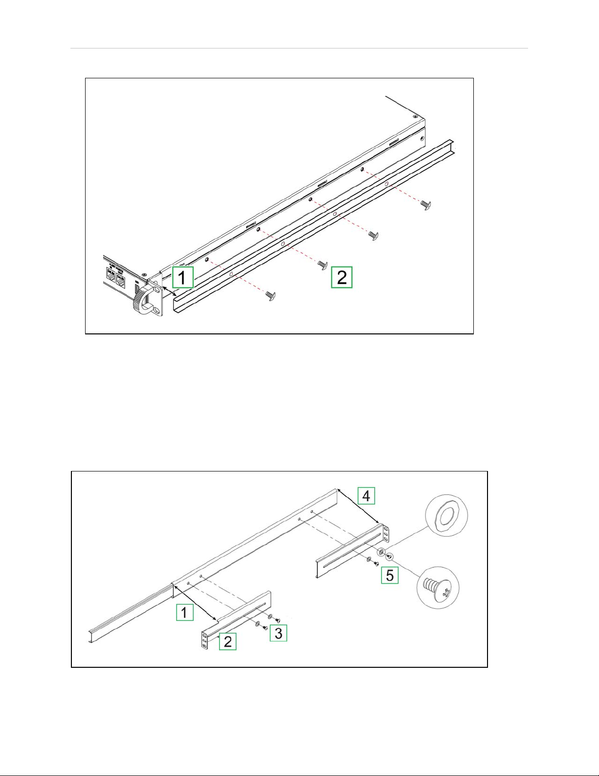
Remove the Sliding Rail from the Track
Remove the sliding rail from the telescoping track as follows:
Figure 3-3. Remove the Rail From the Track (Right Assembly Shown).
1.
Pull the end of the sliding rail [1] until it is fully extended from the track [2] engaging
the locking button [3].
2.
Press the locking button [3] and continue to pull the sliding rail [1] removing it completely from the track.
3.
Repeat Step 1 and Step 2 for the second rail assembly.
Attach the Sliding Rail to the Chassis
Attach the sliding rail to the appliance chassis as follows:
14413-200 Rev. A Enterprise Manager 2100 User’s Guide 29
Page 30
3.4 Sliding Rail Kit for Rack Mounting
Figure 3-4. Attach the Rail to the Appliance Chassis (Right Assembly Shown).
1.
Align the end of the sliding rail with the notch in the chassis pull brackets [1].
2.
Attach the rail with four 6 mm M4 screws [2]. Torque each screw to 2 ft-lb (3 N∙m).
3.
Repeat Step 1 and Step 2 for the second sliding rail.
Attach the Adjustable Brackets to the Track
Attach the larger, adjustable L-shaped brackets to the telescoping track as follows:
Figure 3-5. Attach the Large L-Brackets to the Track (Right Assembly Shown).
30 Enterprise Manager 2100 User’s Guide 14413-200 Rev. A
Page 31

Chapter 3: Installation
1.
Identify the brackets by a letter stamped into the metal: F—Front and R—Rear.
2.
Align the front bracket [2] with the front end of the outer track [1].
3.
Attach the front L-bracket with two 4 mm M4 black screws and washers [3]. Torque
each screw to 2 ft-lb (3 N∙m).
4.
Align the rear bracket with the rear end of the outer track [4].
5.
Attach the rear L-bracket with two 4 mm M4 black screws and washers [5]. Tighten
each screw loosely, enabling the bracket to slide.
6.
Repeat Step 1 through Step 5 for the second track.
Determine the Mounting Method for the Sliding Rail Kit
Determine which fastener holes you will use to attach the sliding rail kit to the rack posts. The
sliding rail kit adapts to different rack post profiles in several ways:
l
Adjust the position of the L-bracket to contact the inner or outer surfaces of the rack
post.
l
Rotate the L-clamp as necessary to clamp and fasten the L-bracket to the rack posts.
l
For some rack post profiles, you might be able to attach the L-bracket directly to the post
without requiring the L-clamp.
Attach the Track to the Rack Posts
The following procedure is typical of most rack post profiles.
Adjust the Track to Span the Rack Posts
Move the rear L-bracket so that both L-brackets span the outer faces of the front and rear rack
posts as follows:
1.
Use masking tape to mark all four U-locations on the rack posts.
2.
Position the track so that the front L-bracket is on the outer face of the front rack post.
3.
Slide the loose rear L-bracket [1] until it aligns tightly with the outer face of the rear rack
post. Temporarily tape the rear L-bracket to the track to prevent it from moving.
4.
Tighten the two 4mm M4 black screws and washers to secure the L-bracket to the track.
Torque each screw to 2 ft-lb (3 N∙m).
14413-200 Rev. A Enterprise Manager 2100 User’s Guide 31
Page 32

3.4 Sliding Rail Kit for Rack Mounting
Figure 3-6. Adjusting and Attaching the Track to the Rack Posts
Attach the Track to the Rack Posts
Attach the track to the rack post as follows:
1.
Position the track so that the L-clamps are on the outer faces of the front an rear rack
posts. Temporarily tape (or have someone hold) the track in position.
2.
Place an L-clamp [2] on the inner face of the front rack post.
3.
Secure the front L-bracket to the L-clamp with two 8mm M5 screws [3], using only the
top and bottom holes at the U-location. Torque each screw to 4.5 ft-lb (6 N∙m).
4.
Repeat Step 2 for the L-clamp at the rear rack post [3].
5.
Repeat Step 1 through Step 4 for the remaining track.
6.
Check that both slides operate smoothly and do not bind and that the tracks are level
and straight.
32 Enterprise Manager 2100 User’s Guide 14413-200 Rev. A
Page 33
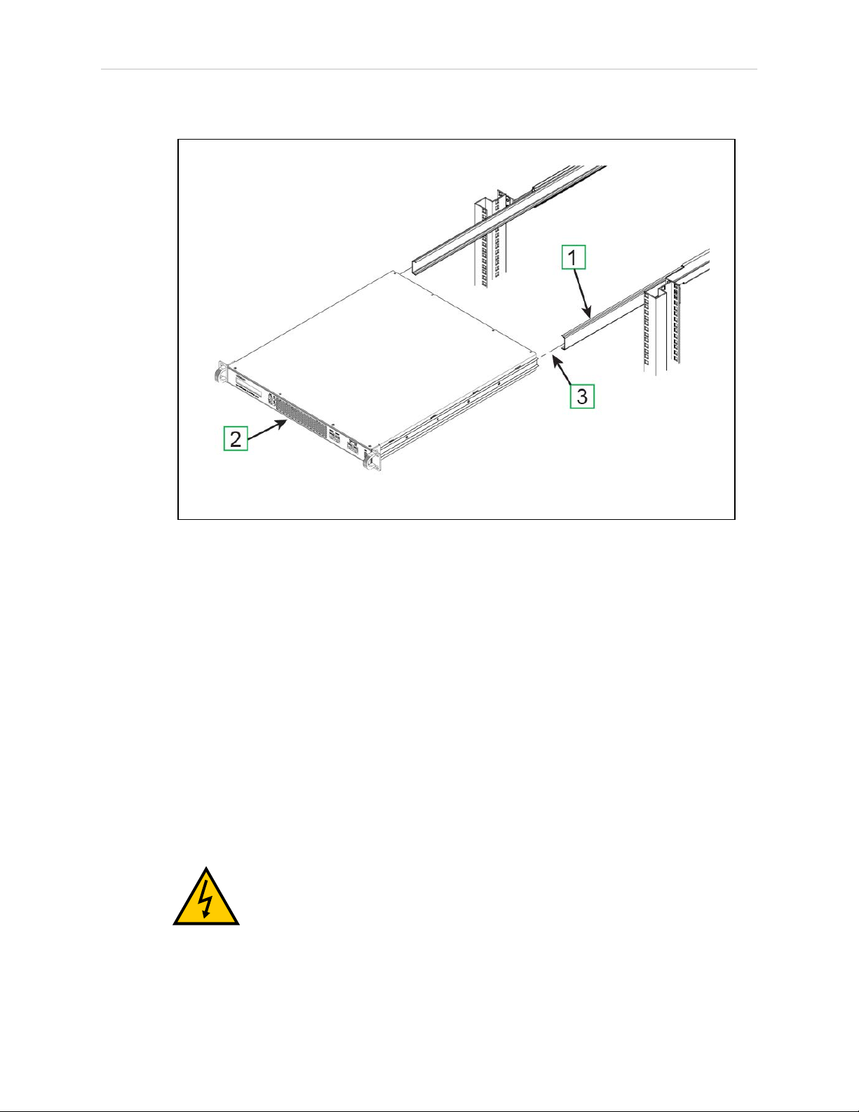
Insert the Appliance Into the Track
Chapter 3: Installation
Figure 3-7. Inserting the Chassis Into the Track
1.
Slide the telescoping track out a few inches on each side [1].
2.
Hold the chassis level and square with the rack [2].
3.
Insert the rails into the tracks and push the chassis all the way in until you hear the
rails click and lock.
4.
Carefully and slowly pull the chassis out again to full extension, making sure that the
rail stops at the lock (See [3] in Figure 3-3.
5.
Lock in place with an M5 screw.
3.5 Connect Power to the Enterprise Manager 2100
The appliance requires a 100 – 240 VAC, 50/60 Hz power supply. Omron Adept Technologies,
Inc. recommends that you use a separate uninterruptable power supply (UPS) circuit for each
appliance.
WARNING: ELECTROCUTION RISK. Make sure that all connections and
supply equipment is operationally safe and follow all local regulations concerning the electrical installation of computer devices.
14413-200 Rev. A Enterprise Manager 2100 User’s Guide 33
Page 34

3.6 Plan for Disaster Tolerance
AVERTISSMANT: RISQUE D'ÉLECTROCUTION. S’assurer que toutes les
connexions et les équipements d’alimentation sont sûrs du point de vue opérationnel et respecter toutes les réglementations locales concernant l’installation
électrique des dispositifs informatiques.
1. Connect the AC plug on the rear of the appliance to AC power.
2. Set the rear power switch to ON (I).
3. Use only the front momentary power switch to control AC power during normal operation.
3.6 Plan for Disaster Tolerance
Installing a Secondary appliance in a remote location (you must meet all networking requirements) might enable your fleet to tolerate some potential disaster events. A catastrophic local
event that affects the Primary Appliance might not affect the Secondary. When a Secondary
appliance is available and running, you can quickly recover your AIV fleet operations.
A Secondary appliance is one that is ready to take over operation if the Primary appliance
fails. You can install a Secondary appliance as a standby for the Primary. Consider additional
planning for disaster tolerance by including UPS, redundant power, and redundant network
switching. Such device and power redundancy will help you to recover more quickly with
little or no data loss.
IMPORTANT: If you have an EM2100 and an EM1100, you must always use
the EM1100 as a Secondary appliance. See Supported Enterprise Manager 2100
Deployments on page 14.
If you install a Secondary appliance, follow the hardware procedure described for the Primary
appliance. While you can choose to install a Secondary appliance in the same rack as the
Primary appliance, connect it to a different UPS and also to a different network switch.
Connect a Secondary appliance to the same network subnet as the primary and consider the
following options for a reliable and trouble-free operation:
l Install the Secondary appliance in a different (remote) location in the building.
l Connect each appliance to a separate power circuits and UPS.
l Connect each appliance to separate, interconnected Ethernet switches.
l Connect each Ethernet switch to separate power circuits and UPS.
3.7 Installing a Secondary Appliance
If you are installing a Secondary appliance to create an Autosync pair, follow the procedure
described for the Primary appliance. While you can install a Secondary appliance in the same
rack as the Primary appliance, you should always connect it to a different UPS and also to a
different network switch.
Installing the Secondary appliance in a remote location (providing you meet all networking
requirements) is a better solution for redundancy. A catastrophic local event that affects the
Primary appliance will not affect the Secondary. If the Secondary appliance is available and
34 Enterprise Manager 2100 User’s Guide 14413-200 Rev. A
Page 35

Chapter 3: Installation
running you can quickly recover fleet operations. See Installing a Secondary Appliance on
page 34.
14413-200 Rev. A Enterprise Manager 2100 User’s Guide 35
Page 36

Page 37

Chapter 4: Connectors and Indicators
This section describes the available appliance connections, controls and indicators. It includes
the following topics.
4.1 Overview of the Enterprise Manager 2100
4.2 Rear Panel Connectors and Features
4.3 Enterprise Manager 2100 Status Display Panel
4.4 Connect the Enterprise Manager 2100 to a Network
4.1 Overview of the Enterprise Manager 2100
This section describes the connectors, indicators, and physical characteristics of the Enterprise
Manager appliance, shown in Figure 4-1.
37
38
39
40
Figure 4-1. Enterprise Manager 2100 Appliance Front Panel Features and Connectors
The front panel features are described in Table 4-1.
Table 4-1. EM2100 Front Panel features
Callout Label Port Description
1 n/a n/a Pull handle for removing the appliance from the rack (when moun-
ted in a sliding rail kit only).
2 n/a n/a Display panel. This 40-Char (2x20) LCD display provides status,
warning, and error information. For details, see: Enterprise Manager
2100 Status Display Panel.
3 PWR n/a Momentary power switch. Press and release immediately to switch
power on or off, such as when you intend to restart the appliance
manually (a soft restart).
14413-200 Rev. A Enterprise Manager 2100 User’s Guide 37
Page 38
4.2 Rear Panel Connectors and Features
Callout Label Port Description
If you press and hold the power switch for longer than 4 seconds it
causes an immediate software halt (a hard stop).
4 SYS n/a System indicator LED. Illuminated green during normal operation.
5 HDD n/a Storage activity indicator LED. Illuminated red during hared drive
access (data reads and writes).
6 MAINT ETH0 Maintenance Ethernet network port. Use the Maintenance port for
initial setup, troubleshooting, and as an alternate method of access.
Its IP address is fixed at 1.2.3.4, and it requires no password.
7 MGMT ETH1 Management Ethernet network port.
8 FLEET ETH2 Fleet Ethernet network port. This is a general-purpose LAN con-
nection, used by both AIVs and MobilePlanner for appliance connections.
9 SYNC ETH3 Synchronize Ethernet network port. Not used in this release.
10 KEY n/a Front USBport (Service use only).
NOTE: When operating in standalone configuration, the appliance uses only the
AC power, the Management Ethernet connector, and the Fleet Ethernet connector.
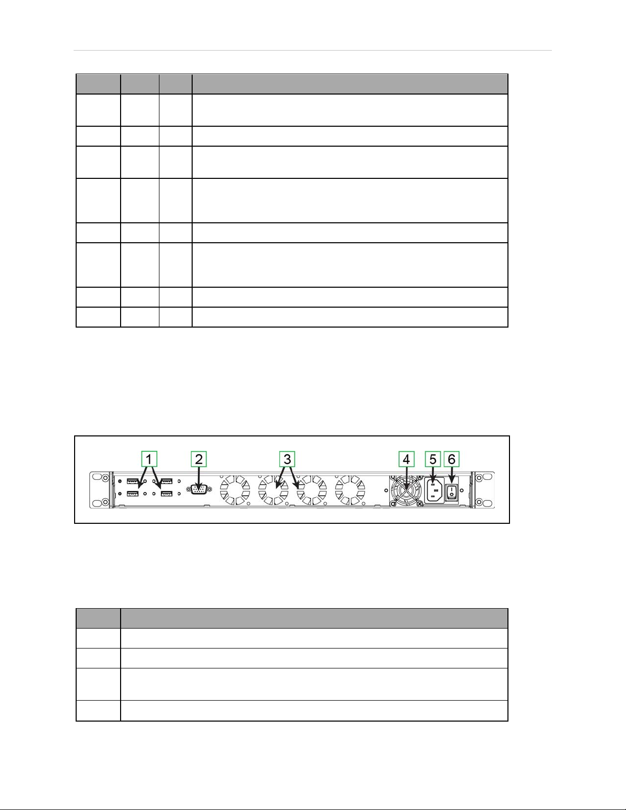
4.2 Rear Panel Connectors and Features
The EM2100 provides the rear panel connectors and features shown in Figure 4-2.
Figure 4-2. EM2100 Rear Panel Connectors and Features
The EM2100 rear panel connectors and features are described in Table 4-2.
Table 4-2. Description of EM2100 Rear Panel Connectors and Features
Callout Description
1 Four USB Ports, for service use only.
2 SVGA Video DB9 port, for service use only.
3 Four auto-speed motherboard cooling fans. Fan speed (and noise volume) varies
depending on the CPU load and the ambient temperature.
4 Power supply cooling fan.
38 Enterprise Manager 2100 User’s Guide 14413-200 Rev. A
Page 39

Chapter 4: Connectors and Indicators
Callout Description
5 IEC 60320 C14 Power Input connector
6 Mains power switch. Keep this set to on (I) and use the front power switch to control
power.
4.3 Enterprise Manager 2100 Status Display Panel
The Enterprise Manager 2100 includes an LCD status display panel that provides the information shown in Table 4-3.
Table 4-3. Enterprise Manager 2100 Status Display Messages
Message Description
OMRON ADEPT
TECHNOLOGIES
EM2100 STARTING Boot message after power on.
MODE: Fleet Manager
LINK:↑↓↓↑
ETH2:<###.###.###.###>
ETH1: <###.###.###.###>
ASYNC: <mode>
STATUS: <status>
UP:<time> Time elapsed since the last reboot.
Standard splash message during power on.
The operating mode of this appliance.
Indicates which Ethernet ports are in use (connected and
active). An up arrow (↑) indicates that the port is in use, a
down arrow (↓) indicates that the port is not in use.
IPv4 address for the Fleet Ethernet port.
IPv4 address for the Management Ethernet port.
Whether the EM2100 is a Primary or Secondary appliance
in an Autosync pair.
The status of an Autosync pair: Disabled, Startup, Active,
or Failed. See the description below,
Autosync Status
The status of an Autosync pair, which can be:
l
Disabled—The current appliance is Primary, but the Secondary IP Address is 0.0.0.0.
Autosync is disabled without a valid Secondary appliance IP Address.
l
Startup—Autosync is configured, but the two appliances have not yet communicated
successfully.
l
Active—Primary and Secondary appliances are communicating.
l
Failed—Primary and Secondary appliances are communicating, but the connection is
lost. The Primary appliance automatically attempts to re-establish communication with
the Secondary appliance.
14413-200 Rev. A Enterprise Manager 2100 User’s Guide 39
Page 40

4.4 Connect the Enterprise Manager 2100 to a Network
!
4.4 Connect the Enterprise Manager 2100 to a Network
To use a single Enterprise Manager 2100 as a standalone appliance, connect the Ethernet ports
as shown in Figure 4-3.
Figure 4-3. Single Enterprise Manager 2100 as a Standalone Fleet Management Appliance
Omron Adept Technologies, Inc. recommends that you use cables that meet a minimum
requirement of Category 5e. The connections are described in Table 4-4.
Table 4-4. Cabling a Single Enterprise Manager 2100
Callout Label Port Description
1 n/a n/a Enterprise Manager 2100 configured in standalone mode. n/a
2 MAINT ETH0 The Maintenance port that you use for initial con-
figuration and for emergency access in future. This port
has a fixed IP address of 1.2.3.4.
3 MGMT ETH1 The Enterprise Manager 2100 Management port. LAN
4 FLEET ETH2 The Fleet administrative port. LAN
CAUTION: NETWORK SECURITY. Do not connect the Enterprise Manager
appliance directly to the Internet. If the Enterprise Manager appliance is on a
LAN that has Internet access, make sure there is a firewall between the LAN
and the Internet in order to prevent unwanted and unauthorized network
traffic from reaching the Enterprise Manager appliance.
Cable
Client
Windows
PC
Switch
Switch
To
40 Enterprise Manager 2100 User’s Guide 14413-200 Rev. A
Page 41

Chapter 4: Connectors and Indicators
!
ATTENTION: SÉCURITÉ DU RÉSEAU. Ne pas connecter l’appareil Enterprise Manager directement à Internet. Si l’appareil Enterprise Manager est connecté à un réseau LAN avec accès à Internet, assurer la présence d’un pare-feu
entre le réseau LAN et Internet afin de prévenir le trafic réseau non désiré et
non autorisé d’atteindre l’appareil Enterprise Manager..
14413-200 Rev. A Enterprise Manager 2100 User’s Guide 41
Page 42

4.4 Connect the Enterprise Manager 2100 to a Network
Logical Ports and Protocols Used by the Enterprise Manager 2100
An Enterprise Manager 2100 requires the logical ports and protocols described in Table 4-5.
Table 4-5. Logical Ports and Protocols
Protocol Port(s) Initiator toRecipient
Intra-fleet Communications
Used to broadcast configuration updates to AIVs, to dispatch job commands, and to share position and trajectory updates throughout the fleet.
TCP 37 AIV to Enterprise Manager appliance Maintenance, Man-
agement and Fleet ports use this.
TCP/UDP 5000 AIV Enterprise Manager. Fleet port uses this.
UDP Range
10000 and
up
TCP/UDP 7272 AIV to Enterprise Manager appliance
Configuration and Monitoring of Fleet
Used for MobilePlanner connections to the Enterprise Manager appliance and AIVs for monitoring and configuration.
TCP 443 Client PC to Enterprise Manager appliance
TCP/UDP Range 7272
and up
TCP/UDP 7272 Client PC to AIV
UDP Range
10000 and
up
AIV to Enterprise Manager appliance
This protocol uses as many ports as there are AIVs in a fleet.
Each connecting AIV uses the next available port >= 10000.
For best results, allow a large number of ports such as 10000-
10999.
Maintenance and Management ports use this.
Client PC to Enterprise Manager appliance
This protocol uses as many ports as there are AIVs. Each AIV
that connects uses the next available port >= 7272.
For best results, allow a large number of ports, such as 7272-
7999.
Enterprise Manager appliance to Client PC
This protocol uses as many ports as there are AIVs. Each AIV
that connects uses the next available port >= 10000.
For best results, allow a large number of ports such as 10000-
10999.
UDP 10000 AIV to Client PC.
Job Monitoring and Submission (ARCL Interface)
Used for managing jobs on the Enterprise Manager appliance. These are typically submitted
from a Warehouse Management System (WMS) or Manufacturing Execution System (MES).
TCP 7171 WMS/MES to Enterprise Manager appliance
ARCL Server: if enabled in the configuration (Robot Interface
and then ARCL Server Setup), this port is open on the Enter-
42 Enterprise Manager 2100 User’s Guide 14413-200 Rev. A
Page 43

Chapter 4: Connectors and Indicators
Protocol Port(s) Initiator toRecipient
prise Manager and accepts unlimited incoming connections. The
port number is configurable.
(This port might be available on the AIV, depending on the
application.)
TCP Configurable
port #
Optional
TCP 123 Enterprise Manager appliance to NTP server
UDP/TCP Range
100065535
Enterprise Manager appliance to WMS/MES
Outgoing ARCL Connection: if enabled in the configuration
(Robot Interface then Outgoing ARCL connection setup), then
the Enterprise Manager initiates an outgoing connection to the
specified hostname and TCP port number.
If you enable a Network Time Protocol (NTP) client Enterprise
Manager appliance (SetNetGo then System and then
Date/Time), the Enterprise Manager appliance attempts to set
its clock from the network time server at the specified IP
address. (This function is available on the AIV, if you do not use
a client Enterprise Manager appliance.)
Offboard devices to AIV
If RS232 or Ethernet Port Forwarding is enabled on the AIV
(SetNetGo then Network) then the configured TCP ports are
open on the AIV for incoming connections.
Logical Ports and Protocols Used by a Single AIV
An individual AIV in a Fleet requires the following logical ports and protocols.
Protocol Port(s) Initiator ðRecipient
Configuration and Monitoring of AIV
Used for MobilePlanner connections to the AIV for purposes of monitoring and configuration.
TCP 443 Client PC to AIV
TCP/UDP 7272 Client PC to AIV
UDP 10000 AIV to Client PC
Job Monitoring and Submission (ARCL Interface)
Used for managing jobs on the Enterprise Manager. These are typically submitted from call buttons or other automation equipment
TCP 7171 Offboard devices to AIV
ARCL Server: if enabled in the configuration (Robot Interface and
then ARCL Server Setup), then this port is open on the AIV and
accepts unlimited incoming connections. The port number is configurable.
TCP Configurable
port #
Off-board Devices to AIV
Outgoing ARCL connection: If enabled in the configuration (Robot
Interface and then Outgoing ARCL connection setup), then the
AIV initiates an outgoing connection to the specified hostname
and TCP port number.
14413-200 Rev. A Enterprise Manager 2100 User’s Guide 43
Page 44

4.4 Connect the Enterprise Manager 2100 to a Network
Protocol Port(s) Initiator ðRecipient
Optional
TCP 123 AIV to NTP server
If the Network Time Protocol (NTP) client is enabled on the AIV
(SetNetGo then System and then Date/Time), the AIV attempts
to connect to the configured IP address to synchronize its clock.
UDP/TCP Range
100065535
Off-board Devices to AIV
If RS232 or Ethernet Port Forwarding is enabled on the AIV
(SetNetGo then Network), the configured TCP ports are open on
the AIV for incoming connections.
44 Enterprise Manager 2100 User’s Guide 14413-200 Rev. A
Page 45

Chapter 5: Configuration
This chapter describes the data connections and configuration of the Enterprise Manager appliance. It includes the following topics.
5.1 Enterprise Manager 2100 Configuration Overview
5.2 Set the IP Address on a Client PC's Network Adapter
5.3 Connect Your PC to SetNetGo on the Enterprise Manager 2100
5.4 Configure Management Interface Network Settings
5.5 Configure the Fleet Interface Network Settings
5.6 Use NTP to Synchronize Enterprise Manager 2100 Time
5.7 Enabling the ARCL Server
5.8 Configure Each AIV to Connect to the Enterprise Manager
5.9 Add a Secondary Appliance for AutoSync
5.10 Configure a Secondary Appliance and Autosync
5.11 Customize Each Fleet AIV
5.12 Call Buttons
5.1 Enterprise Manager 2100 Configuration Overview
Enterprise Manager 2100 Configuration varies depending on how you deploy the appliance.
See Supported Enterprise Manager 2100 Deployments on page 14.
Ethernet Connections
45
47
47
49
50
51
52
52
54
54
57
59
The Enterprise Manager appliance provides four built-in Ethernet ports described in: Connect
the Enterprise Manager 2100 to a Network on page 40.
Table 5-1. EM2100 Ethernet Ports
Port Description and Use IP Address
MAINT ETH0
(Maintenance
Port)
MGMT ETH1
(Management
Port)
FLEET ETH2
(Fleet Management Port)
The Maintenance port is always enabled and is not password
protected. Use this port only configure the appliance or for
administrative access.
The SetNetGo access Ethernet port. You can define the
IPaddress.
AIVs cannot access this Ethernet port.
The port for AIV and MobilePlanner operational connections.
You can define the IPaddress. This is the connection port for
all AIVs, and also for the MobilePlanner client.
Fixed: 1.2.3.4
User defined
User defined
14413-200 Rev. A Enterprise Manager 2100 User’s Guide 45
Page 46

5.1 Enterprise Manager 2100 Configuration Overview
Port Description and Use IP Address
SYNC ETH3
Not used in this release. None
(Autosync
Port)
Contact your System Administrator for assistance configuring the Enterprise Manager appliance for your network. See also: Site Networking Requirements on page 23.
Configuration Tasks Overview
To connect to and configure the Enterprise Manager appliance, you must do the following
tasks, which are described in detail later in this guide:
l
Set an IP address on your PC's Ethernet adapter.
l
Connect your PC to the Enterprise Manager appliance.
l
Use a browser to access the SetNetGo interface.
l
Configure the network settings for the appliance Management Ethernet port.
l
Configure the network settings for the FLEET ETH2 Ethernet port.
l
Define the login information.
l
Configure each AIV to connect to the Enterprise Manager 2100.
l
Customize each AIV, if desired.
If you also install a Secondary appliance and configure Autosync, you must also:
l
Install the same SetNetGo and ARAMCentral software version on the Secondary as is
on the Primary appliance.
l
Configure a unique IP address for the Management port.
l
Connect the Management port to the LAN.
l
Connect the FLEET ETH2 port to the LAN.
l
Enter the Secondary Management IP address on the Primary appliance.
l
Generate and download a key from the Primary appliance.
l
Set the Secondary appliance Autosync role to Secondary.
l
Upload the key to the Secondary appliance.
l
Verify that the status of both appliances is active.
l
Create a direct network connection between the Primary and Secondary appliances.
46 Enterprise Manager 2100 User’s Guide 14413-200 Rev. A
Page 47

Chapter 5: Configuration
5.2 Set the IP Address on a Client PC's Network Adapter
Use the Maintenance Ethernet port to connect a client PC to the SetNetGo operating system.
IMPORTANT: You must assign a static (fixed) IP address. Do not use a DHCP
server.
Configure the network adapter IPv4 address on the Client PC as follows:
1.
Connect a CAT 5 Ethernet cable from the client PC’s Ethernet port to the Maintenance
Ethernet port on the EM 2100 appliance.
2.
In the command field on the Windows taskbar, enter the following command to open
the Network Connections dialog: ncpa.cpl
3.
Double-click the Ethernet icon to open its Properties dialog, and then click Properties
4. Double-click TCP/IPv4 to open the Internet Protocol properties dialog.
5.
Enter as the IP address: 1. 2. 3. 5, or any IP address in the range 1. 2. 3. 0 to 1. 2. 3. 255,
excluding 1. 2. 3. 4. (this is reserved for the Maintenance port).
6.
Enter as the subnet mask: 255. 255. 255. 0.
7.
Press OK to close the Internet Protocol dialog, and then press OK to close the Ethernet
Adapter dialog.
In future, you can use the Maintenance Ethernet port for emergency access to the Appliance at
IP address 1.2.3.4. (For example, if you lose the password or if there is a network IP address
conflict.)
5.3 Connect Your PC to SetNetGo on the Enterprise Manager 2100
SetNetGo enables you to configure and manage Enterprise Manager 2100 and AIVsettings.
This section describes how to access SetNetGo through the Maintenance port to perform initial
configuration.
The user interface for SetNetGo on an Enterprise Manager appliance provides a different set of
parameters and options compared to SetNetGo on an AIV. The upper left of the screen shows
SetNetGo - ENTERPRISE MANAGER 2100 or SETNETGO - LD, depending on your SetNetGo
context (the device on which it runs, such as the Omron Adept Technologies, Inc. LD Platform).
Connect to SetNetGo and Configure Access and Security
After you connect to the Maintenance Port as described in: Set the IP Address on a Client PC's
Network Adapter on page 47 you can open the SetNetGo Web interface.
NOTE: Passwords are limited to a maximum of 20 alphanumeric characters.
For increased security, specify a long (10+ characters) password string with both
uppercase and lowercase letters. Include several integers.
14413-200 Rev. A Enterprise Manager 2100 User’s Guide 47
Page 48

5.3 Connect Your PC to SetNetGo on the Enterprise Manager 2100
Connect your browser to SetNetGo and configure SetNetGo access as follows:
1.
Open a browser and type: HTTP://1. 2. 3. 4 and then press enter.
2.
If a certificate warning dialog opens, ignore it and close the dialog.
3.
In the SetNetGo web interface, click the Security Tab and then click SetNetGo Access
and check Enabled next to the following:
l Management and Fleet Interface.
l (Optional) Remote reboot.
4.
Change the account password (default is no password) as required and click Apply.
Enable Fleet Account Access
If you want to strictly control access to the Fleet through MobilePlanner you can enable account
access and create authorized user accounts with passwords.
If you enable access control, you must also enable at least the Admin account. You can also:
l
Enable default Operator and Viewer accounts.
l
Create additional user accounts.
l
Modify account permissions to control access privileges.
To enable fleet account access
1.
In the SetNetGo web interface, click the Security Tab and then click Fleet Accounts and
2.
Check Enabled next to Access Control and press Apply.
3. Wait for the change to take effect and refresh your browser if necessary. (You might see
a warning that you enabled access control without creating accounts.)
4.
Check Enabled next to the admin Username.
5.
Enter and confirm a new password, and then click Apply.
6.
Optionally, repeat Step 4 and Step 5 for the default operator and viewer accounts,
which have different access privileges compared to the admin account.
7. Optionally add a new named user account and repeat Step 4 and Step 5. If you create
a new user account you might also want to click the Modify Permissions link to fur-
ther control user access.
Access SetNetGo from Mobile Planner
During normal operation, you access SetNetGo through the MobilePlanner software as follows:
1.
Start the MobilePlanner software on your PC.
2.
Click anywhere in the SetNetGo selection box, to access the SetNetGo interface.
48 Enterprise Manager 2100 User’s Guide 14413-200 Rev. A
Page 49
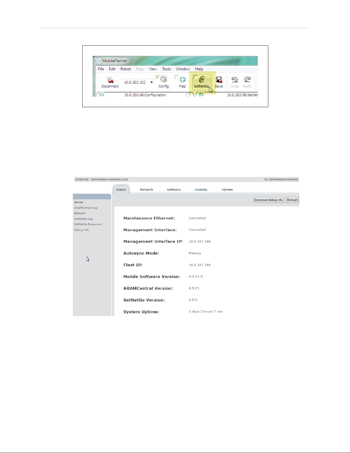
Chapter 5: Configuration
Figure 5-1. Hover Over the SetNetGo Selection Box
Hover over the selection box to reveal its boundaries. (See the cursor in the preceding figure.)
NOTE: It is not necessary to enable (check) the checkbox within the
SetNetGo selection box. The checkbox determines whether SetNetGo starts
automatically when you open MobilePlanner.
Figure 5-2. SetNetGo Interface—Status Tab, Home Screen
This screen provides an overview of link status, IP addresses, and installed software versions.
5.4 Configure Management Interface Network Settings
To configure the Management Network, you require:
l A dedicated static IP address. (Do not use 1.2.3.4. That address is permanently assigned
to the Maintenance Ethernet port.)
l The subnet mask for the Management network.
l The IP address of the network Gateway.
14413-200 Rev. A Enterprise Manager 2100 User’s Guide 49
Page 50

5.5 Configure the Fleet Interface Network Settings
l If there are other devices in the network that communicate with the fleet, you require the
IP address of the network domain (DSN) server, so that the Enterprise Manager appliance can resolve all IP addresses.
Configure the Management Interface network connections as follows:
1.
In the SetNetGo web interface, click the Network Tab.
2.
Click Management Interface and enter the:
a.
IP address.
b.
Subnet mask.
c.
Network Gateway IP address (typically a router).
3.
Enter the IP address of your Domain Name Server (DNS), if required for devices other
than the appliance and the fleet. Otherwise, leave it as 0.0.0.0.
4.
Click Apply.
A message dialog informs you of the status of the change, and whether there is any affect on
operations such as a restart or a time delay before the change takes effect.
5.5 Configure the Fleet Interface Network Settings
To configure the Fleet Interface, you require:
l A dedicated static IP address. Do not use 1.2.3.4. That address is permanently assigned
to the Maintenance Ethernet port.
l The subnet mask for the network that your Fleet will use.
l The IP address of the network Gateway
Configure the Fleet Interface network connections as follows:
1.
In the SetNetGo web interface, click the Network Tab.
2.
Click Fleet Interface and enter the:
a.
IP address.
b.
Subnet mask.
c.
Network Gateway IP address (typically a router).
3.
Click Apply.
A message dialog informs you of the status of the change, and whether there is any affect on
operations such as a restart or a time delay before the change takes effect.
50 Enterprise Manager 2100 User’s Guide 14413-200 Rev. A
Page 51
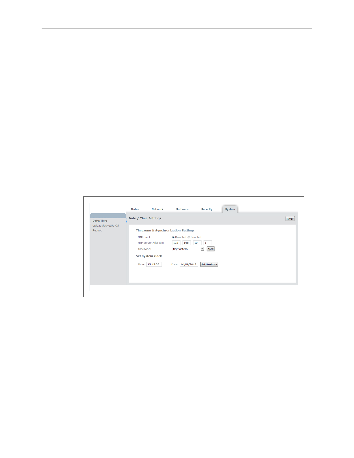
Chapter 5: Configuration
5.6 Use NTP to Synchronize Enterprise Manager 2100 Time
You can either specify the system time manually or configure the Enterprise Manager appliance to synchronize Network Time Protocol (NTP).
When you use NTP:
l
The Enterprise Manager appliance synchronizes its clock with NTP as a client of the
NTP server.
l
Fleet AIVs synchronize their clocks with the Enterprise Manager appliance, regardless
of their time settings. Even if you configure a fleet AIV to use NTP, it ignores the NTP
settings and synchronizes its clock only with the Enterprise Manager appliance.
To set the date and time manually:
1.
Open SetNetGo and click the System tab.
2.
Select Date/Time.
3.
Set the system clock manually by typing in the Time and Date fields.
4.
Click Set time/date.
Figure 5-3. Date and Time Settings
To use an NTP server:
1.
Open SetNetGo and click the System tab.
2.
Select Date/Time.
3.
Click the Enabled button next to NTP client.
4.
Enter the IP address of the NTP server.
5.
Select your time zone from the Timezone pull-down menu.
6.
Click Apply.
It might take a few minutes for all AIVs in the fleet to update their internal clocks.
14413-200 Rev. A Enterprise Manager 2100 User’s Guide 51
Page 52

5.7 Enabling the ARCL Server
5.7 Enabling the ARCL Server
The ARCL server enables automation systems such as WMS, MES or robot control application
to communicate with the Enterprise Manager 2100 through a text -based TCPport. For more
information about ARCL, see: Software Supplied with the Enterprise Manager 2100 Systems.
Use MobilePlanner to manually enable ARCL as follows:
1.
From MobilePlanner, Config select Robot Interface and then ARCL server setup.
2.
In the OpenTextServer field, use the drop-down box to select True.
The default port is 7171.
3.
Enter a password in the Password field.
4.
Click Save.
5.8 Configure Each AIV to Connect to the Enterprise Manager
Before you can use the Enterprise Manager appliance to manage AIVs, you must configure
each AIV to connect to the appliance. To do so, you must connect to each AIV.
When an AIV connects to the appliance, the Mobile Robot Software Suite overwrites the AIV's
configuration parameters with Fleet parameters.
IMPORTANT: If you have not previously used the Mobile Robot Software Suite,
review the Mobile Robot Software Suite User's Guide before you proceed to connect an AIV to the Enterprise Manager 2100.
AIV Configuration Settings
To connect an AIV to the Enterprise Manager 2100 :
1.
Launch MobilePlanner on your client PC and connect to the AIV's IP address.
2.
Open the Config tab.
52 Enterprise Manager 2100 User’s Guide 14413-200 Rev. A
Page 53
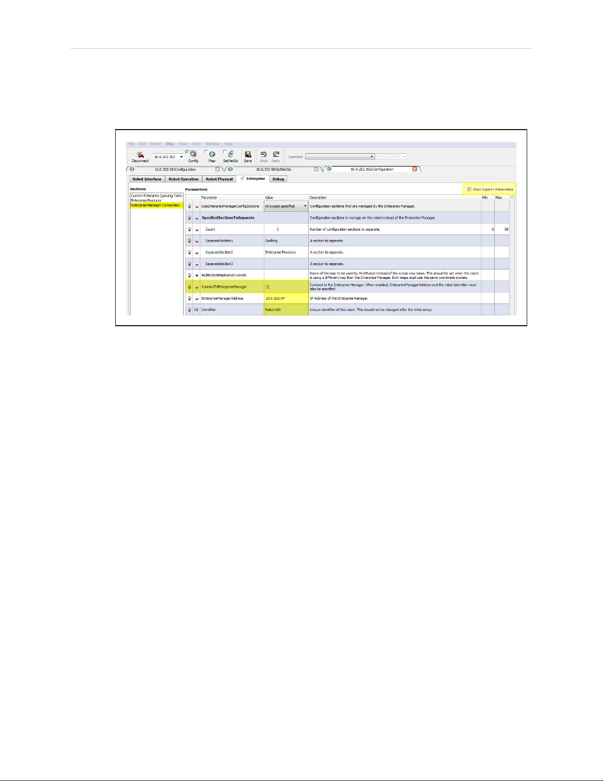
Chapter 5: Configuration
3. Check Expert+ Parameters to show the advanced configuration parameters.
4.
From MobilePlanner, Config select Enterprise and then Enterprise Manager
Connection.
Figure 5-4. Enterprise Manager Connection Screen
5.
Check the ConnectToEnterpriseManager checkbox.
6.
Enter the IP address of the Enterprise Manager 2100 appliance in the
EnterpriseManagerAddress field.
NOTE: This is the Fleet IPaddress, not the Management IP address of the
Enterprise Manager appliance.
7.
Enter an identifier in the Identifier field. You must use unique identifiers for each AIV.
Do not change this identifier after initial setup.
Repeat these steps for each AIV that you want to add to the fleet controlled by this Enterprise
Manager appliance.
Fleet-Level Settings
From MobilePlanner, Config, on the Enterprise Manager 2100:
1.
Select Enterprise and then Enterprise Features.
2.
Check the EnterpriseManagerGatherScans box.
This enables the Mobile Robot Software Suite to gather any scan files created by the
AIVs.
3.
Back up (copy) any required maps to a storage location.
4.
[OPTIONAL] Check DeleteUnusedMaps to permanently delete unnecessary map files
from each AIV.
14413-200 Rev. A Enterprise Manager 2100 User’s Guide 53
Page 54

5.9 Add a Secondary Appliance for AutoSync
5.9 Add a Secondary Appliance for AutoSync
Install an optional Secondary Enterprise Manager appliance to provide redundancy for the
Primary appliance.
You can auto-synchronize (Autosync) a Secondary appliance to a Primary appliance, enabling
faster recovery should the Primary appliance fail for any reason.
The Autosync feature copies Fleet data from the Primary Appliance to the Secondary Appliance. This data includes:
l The central configuration for AIVs.
l The workspace map.
l Payload information.
l The Pending job queue.
To make sure that synchronization persists, Autosync maintains a constant heartbeat signal on
the network between appliances. If an appliance fails to respond, the lack of a response indicates a possible failure of the appliance, or of network communications between the appliances.
An error message notifies you of the failure so that you can diagnose and correct the problem.
You use the SetNetGo Web interface to configure Autosync, which involves specifying an
authentication key to join two appliances into a pair and establish their autosync roles.
Setting up an optional Secondary appliance is described in Installation on page 21 and Configuration on page 45.
5.10 Configure a Secondary Appliance and Autosync
The default (shipped) configuration for an Enterprise Manager 2100 is for Primary appliance
operation. To create an Autosync pair, you use SetNetGo to configure the existing Primary to
communicate with the Secondary. The paired appliances then function as follows:
l
The Primary unit is a fully-functional Enterprise Manager appliance, running the
Mobile Robot Software Suite and actively controlling the fleet.
l
The Secondary unit is powered on, with its Web interface accessible to the Primary unit.
However, the Mobile Robot Software Suite is inactive on the Secondary unit, and it is
inaccessible from MobilePlanner or AIVs.
The Primary appliance has two active IP addresses, while the Secondary has only one active
IP address.
This release supports mixed model EM2100 and EM1100 configurations, but you must use the
EM1100 only as a Secondary appliance. For more information, see: Supported Enterprise Manager 2100 Deployments on page 14.
54 Enterprise Manager 2100 User’s Guide 14413-200 Rev. A
Page 55

EM2100-Only Autosync — Ethernet Cabling
Figure 5-5. shows the physical connection of Ethernet cables to the appliances.
Figure 5-5. Cabling for an EM2100-Only Autosync Configuration.
Chapter 5: Configuration
Callout Description
1 EM2100 configured as a Primary appliance.
2 EM2100 configured as a Secondary appliance.
3 Cat-V Ethernet cables to the LAN switch:
l Primary and Secondary MGMT ETH1
l Primary and Secondary FLEET ETH2
EM2100 and EM1100 Autosync — Ethernet Cabling
Figure 5-6. shows the physical connection of cables to the appliances.
Figure 5-6. Cabling for an EM2100 and EM1100 Autosync Configuration.
14413-200 Rev. A Enterprise Manager 2100 User’s Guide 55
Page 56

5.10 Configure a Secondary Appliance and Autosync
Callout Description
1 EM2100 configured as a Primary appliance.
2 EM1100 configured as a Secondary appliance.
3 Cat-V Ethernet cables to the LAN switch:
l Primary MGMT
l Secondary FLEET PORTS IN
l Secondary MGMT
4 Appliance interconnection:
l From the FLEET (ETH2) connector of the EM2100.
l To the FLEET PORTS IN connector of the EM1100.
Tasks in Autosync Setup
Before you set up Autosync, make sure that you have:
l
Installed the Primary appliance and connected it to the network.
l
Configured the Maintenance Ethernet interface on the Primary appliance.
l
Physically installed the Secondary appliance hardware, as described in: Installing a Secondary Appliance on page 34.
The tasks required to set up autosync between a Primary and Secondary appliance are:
l
Configure the Primary appliance with a Fleet IP Address.
l
Enter the Secondary appliance IP Address in the Primary appliance.
l
Generate and Download the Primary key (to your PC).
l
Set the Secondary appliance Autosync role to Secondary.
l
Upload the Primary key to the Secondary appliance.
Configure the Primary Appliance
Do this only if you have two Enterprise Manager appliances, and you want to configure one
as a Primary Autosync appliance. You must first configure the Management and Fleet networks and cable the appliances. Primary is the default role for an Appliance.
1.
In the SetNetGo web interface, click the Software tab, then Autosync.
2.
Set the Autosync role to Primary.
3.
Enter the IP Address of the Secondary appliance.
4.
Click Generate New Key to create an SSL key, or Download Existing Key, if you pre-
viously created an SSL key.
5.
You are prompted for a location to save the key file. Save the key locally on your PC,
so you can later upload it to the Secondary appliance.
6.
Enter a location (path) where you want to save the file.
56 Enterprise Manager 2100 User’s Guide 14413-200 Rev. A
Page 57

Chapter 5: Configuration
7.
A warning message indicates the pending disconnection of AIVs and clients. Click
Ok.
Uploading the SSLkey to the Secondary appliance grants permission for the Primary to perform RPC calls required for synchronization.
Configure the Secondary Appliance
Do this only if you have two Enterprise Manager appliances, and you want to configure one
as a Secondary Autosync appliance. You must first:
l
Configure the Management and Fleet networks and cable the appliances.
l
Configure a Primary appliance.
1.
From SetNetGo on the Secondary appliance, select Software and then Autosync.
2.
Select Secondary for the Autosync rolefield.
3.
Click Apply.
A warning message indicates that you must reconfigure AIVs to user the new IP
address. Click Ok.
4.
Click Choose File to select the Primary SSLkey from your PC.
Enter the name and path of the file to upload the key from the PC.
5.
Click Upload.
NOTE: Although the Fleet Interface settings are saved for the Secondary appliance, the interface is inaccessible.
When the connection is complete, the Primary and Secondary appliances show a Current
Status of active.
5.11 Customize Each Fleet AIV
Use MobilePlanner, Config Software to set the mode for docking station for each AIV.
Be aware that docking behavior is also affected by other parameters such as parameters that
control failed docking attempts. For example, if an AIV fails to dock at an assigned dock (perhaps because it is blocked) and the failure occurs three times, it ignores that docking station for
60 minutes.
Available docking stations are valid recharging locations that are:
l
Unoccupied by another AIV.
l
Not currently ignored by the AIV (because of previous failed attempts to dock).
Docking Station Assignment
There are three modes that you can use to specify an AIV's docking and battery charging behavior. To access the relevant docking parameters:
14413-200 Rev. A Enterprise Manager 2100 User’s Guide 57
Page 58

5.11 Customize Each Fleet AIV
1.
Open MobilePlanner connect to the AIV's IP Address.
2.
Navigate to Robot Operation and then Docking.
3.
Enable Show Expert+ Parameters.
Default Mode
When an AIV requires a recharge, it uses the nearest available docking station.
1.
Leave PreferredDock at the default setting (no value specified).
2.
Set OnlyUsePreferredDock to False.
Mixed Mode
In mixed mode, the AIV uses a preferred docking station only if that docking station is available . If the preferred option fails, the AIV searches for an alternate docking station.
1.
Select PreferredDock, and enter the name of the docking station that is preferred for the
AIV.
2.
Set OnlyUsePreferredDock to False.
Separate Docking Stations
In this mode, each AIV is assigned its own docking station.
1.
Select PreferredDock, and enter the name of the docking station that is preferred for the
AIV.
2.
Set OnlyUsePreferredDock to True.
Distinct Speech Synthesis Voices
By default, the AIV voice parameters are set at the Enterprise Manager level, and all AIVs use
the same voice.
If desired, each or some AIVs can have independently configured speech-synthesis settings.
This gives you the ability to give every or some AIVs a distinctive voice.
To enable different voices for each AIV:
1.
From MobilePlanner, Config select Enterprise and then Enterprise Config
Management.
2.
Under SectionsToSeparate, increment Count if there are no empty SeparateSectionX
rows, where ‘X’ is a number, with an empty Value field.
3.
Enter the string "Speech Synthesis" in an empty Value field.
4.
Click Save.
The Speech Synthesis section of parameters are now displayed on each AIV, and any
voice that you set on an AIV is controlled by the AIV, rather than overwritten by the
Mobile Robot Software Suite.
58 Enterprise Manager 2100 User’s Guide 14413-200 Rev. A
Page 59

To enable different voices for only some AIVs, use the MobilePlanner software to connect to
each of those specific AIVs and do the following:
1.
Select Enterprise and then Enterprise Manager Connection.
2.
Use the drop-down arrow to change the Value field of UseEnterpriseManagerConfigSections from “All” to “All except specified”.
3.
If there are no SeparateSectionX rows, where ‘X’ is a number, with an empty Value
field, increment the Count parameter.
The Count and SeparateSectionX parameters are not displayed if
UseEnterpriseManagerConfigSections is set to All.
4.
Add the string “Speech Synthesis” to an empty SeparateSectionX Value field.
5.12 Call Buttons
If installed, you can use the call button option to request an AIV from a remote location.
Pressing a call button sends a request to the Enterprise Manager 2100 system, requesting it to
send an AIV to the call button's assigned goal. The Enterprise Manager 2100 responds by
selecting an available AIV, and then assigning the call button's goal to that AIV.
Chapter 5: Configuration
The LDPlatform Peripherals Guide describes call buttons in more detail.
14413-200 Rev. A Enterprise Manager 2100 User’s Guide 59
Page 60

Page 61

Chapter 6: Operation
This chapter describes how to operate the Enterprise Manager appliance. It includes the following topics.
6.1 Turn Enterprise Manager 2100 Power ON and OFF
6.2 Generate a Workspace Map for Your Fleet
6.3 Managing Queuing
6.4 Update the ARAMCentral Software
6.5 Enterprise Manager 2100 Autosync Operation
6.6 Remove and Replace Enterprise Manager 2100 Appliances from Autosync
6.7 What to do if an EM2100 Primary Appliance Fails
6.8 What to do if an EM1100 Autosync Appliance Fails
6.9 Troubleshooting
Be aware that before you proceed, you must complete the steps in Installation on page 21 and
Configuration on page 45.
6.1 Turn Enterprise Manager 2100 Power ON and OFF
Use the front momentary power switch to control AC power. The rear switch should remain
on unless you are uninstalling the appliance.
Safe Power On
Use the following power on procedure only if you are sure that the environment was safely
shut down and is ready to restart. Otherwise, see: Power On After a Hard Shutdown.
61
64
64
71
71
72
74
74
76
1. Press and hold the front Power switch to power-on the Enterprise Manager appliance.
The power LEDilluminates immediately.
2. Observe the boot message sequence in the display panel.
3. If there are no boot errors, the boot sequence can take up to two minutes, typically less.
Soft Shutdown and Power Off
The following procedure initiates a soft shutdown (preferred), where the operating system runs
through a graceful shutdown procedure. For emergency shut down, see Hard Shutdown and
Power Off.
1.
Press and release the front power switch to start the shutdown sequence for the Enterprise Manager appliance.
2.
Wait for the Appliance to beep three times.
3.
Observe the shutdown messages on the control panel.
14413-200 Rev. A Enterprise Manager 2100 User’s Guide 61
Page 62

6.1 Turn Enterprise Manager 2100 Power ON and OFF
4.
The power LEDgoes out when the sequence is complete.
5.
The shutdown takes up to a minute, though typically less.
Hard Shutdown and Power Off
The following procedure initiates a hard shutdown (emergency shut down), where the operating system terminates immediately. Be aware that this procedure terminates AIV jobs in progress, regardless of their status.
1.
Press and hold the front power switch for at least four seconds.
2.
Wait for the Appliance to beep three times.
3.
Observe the shutdown messages on the control panel.
4.
The power LEDgoes out when the sequence is complete.
5.
The shutdown is immediate.
Do not power-on the Enterprise Manager appliance until you have resolved all problems in
the work environment. Then, follow the procedure described in: Power On After a Hard Shutdown.
Power On After a Hard Shutdown
If you previously powered off an Enterprise Manager appliance with an emergency (hard) shutdown, your work environment might be in an indeterminate state. Before you power on:
1.
Make sure that all AIVs:
a.
Have charged batteries.
b.
Are operational, with no error or no E-stop conditions.
c.
Are in the correct locations and properly localized.
2.
Check the operational status of any site-specific automated machinery (such as conveyors) and any in-transit payloads.
3.
Use MobilePlanner to determine the status of jobs-in-progress at the time of the emergency shut down. Re-queue jobs as necessary.
4.
Follow the power-on steps described in: Safe Power On on page 61.
Affect of Power Interruptions on an Enterprise Manager 2100
Omron Adept Technologies, Inc. recommends that you always use an uninterruptible power
supply (UPS) to mitigate the affect of a power interruption. If you use two appliances in an
Autosync configuration for operational redundancy, connect each appliance to separate power
circuits and UPS devices.
Power Interruptions on a Standalone Enterprise Manager 2100
If there is an interruption to the power supply for any reason or duration, a standalone Enterprise Manager appliance automatically returns to its previous power state.
62 Enterprise Manager 2100 User’s Guide 14413-200 Rev. A
Page 63

Chapter 6: Operation
l
A standalone appliance that was shut down and powered off when the interruption
occurred remains shut down after you restore power.
l
A standalone appliance that was powered on when the interruption occurred restarts
automatically after you restore power.
After recovery from a power interruption, the Enterprise Manager appliance saves its job
queue status and recovers the queue automatically after it restarts following a power failure.
This does not apply to an operator-initiated emergency power off. See: Power On After a Hard
Shutdown on page 62.
Power Interruptions on an Autosync Enterprise Manager 2100
This section assumes that you configured Autosync on two appliances and connected each
appliance to separate power circuits for redundancy. Providing that only one circuit was
affected, one appliance should remain operating normally during the power interruption. The
sequence of events and method of recover depends on which appliance is affected:
l
A power interruption on the Primary appliance results in a loss of connectivity with
AIVs and MobilePlanner. You should:
l
Determine whether the problem is a power outage or a loss of network connectivity.
l
Manually reconfigure the Secondary appliance to become the Primary Appliance.
Autosync status is now disabled.
l
Verify that MobilePlanner and AIVs reconnect to the Fleet IP address.
l
Review the job queue status in MobilePlanner and verify the status of AIVs to
make sure that no jobs are incomplete.
l
Revert the current Primary appliance to its previous role as a Secondary appliance.
l
Restore power to the former Primary appliance, which causes a temporary loss of
connectivity with AIVs and MobilePlanner.
ll
Review the job queue status in MobilePlanner and verify the status of AIVs to
make sure that no jobs are incomplete.
l
A power interruption on the Secondary appliance results in no loss of connectivity with
AIVs and MobilePlanner. You should:
l
Verify that MobilePlanner and AIVs reconnect to the Fleet IP address.
l
Review the job queue status in MobilePlanner and verify the status of AIVs to
make sure that no jobs are incomplete.
l Restore power to the Secondary appliance. Fleet operations should be unaffected.
If both Autosync appliances are affected by a power interruption, they both behave as
described in: Power Interruptions on a Standalone Enterprise Manager 2100 on page 62:
l
All fleet operations are terminated during the power interruption.
l
Normal Active Autosync operation resumes automatically after you restore power to
both appliances.
14413-200 Rev. A Enterprise Manager 2100 User’s Guide 63
Page 64

6.2 Generate a Workspace Map for Your Fleet
l
The Primary Enterprise Manager appliance saves its job queue status and recovers the
queue automatically after it restarts.
Automatic recovery of operations might not apply to an operator-initiated emergency power-off
on the Secondary appliance. See: Power On After a Hard Shutdown on page 62.
6.2 Generate a Workspace Map for Your Fleet
Creating and sharing a workspace map for your fleet requires the MobilePlanner software, running on a user-supplied PC. The Mobile Robot Software Suite User's Guide describes the software
and process for generating the map.
Briefly, the tasks involved are:
l
Use a single AIVin manual drive mode to Generate a map.
l
Upload the generated map to the Enterprise Manager appliance and make it the current
map.
l
The map is downloaded automatically to every AIV in the fleet.
The Enterprise Manager appliance communicates with each AIV individually, rather than
doing a broadcast. In addition to maps, the Enterprise Manager appliance downloads fleetcommon configuration parameters to each AIV.
NOTE: If you are doing a trial with a single AIV, save the data and configuration to your PC, and then download from your PC to the Enterprise Manager appliance when you are confident that it is accurate.
6.3 Managing Queuing
This section describes how to manage AIV job queues.
Queuing and Job Definitions
l
Job - a single command issued to the Enterprise Manager, consisting of one or more
related, ordered moves (job segments). Each job has a unique job ID.
l
Job segment - one discreet move assigned to a AIV. A segment consists of a single goal
name, and you can define it as either a PICKUP or a DROPOFF job segment. The goals
might have tasks that are assigned to the AIV, which count as part of the job segment.
Each job segment has a unique ID.
l
Queue - a collection of requested jobs and job segments, stored on the Enterprise Manager 2100, that are either assigned or waiting to be assigned to AIVs.
l
Assigned Job - a job segment becomes assigned after the Enterprise Manager has allocated an AIV to perform the job. A job segment transitions from Pending to InProgress
after assignment.
l
Pickup - a job segment that ends at a goal so that a payload is loaded onto the AIV. If
the first segment of a job is a PICKUP, then the Enterprise Manager 2100 assigns this
job to whichever AIV it decides is most appropriate.
l
Dropoff - a job segment that ends at a goal so that a payload is removed from the AIV.
64 Enterprise Manager 2100 User’s Guide 14413-200 Rev. A
Page 65

Chapter 6: Operation
A DROPOFF segment is handled only by the required AIV.
l
Required Robot - certain job segments are serviced only by a specific AIV. For example,
the DROPOFF segment of a PICKUP-DROPOFF job must be handled by the same AIV
that performed the pickup. Thus, whichever AIV handles the initial PICKUP job is the
required robot for the DROPOFF.
The Enterprise Manager appliance enables you to queue jobs. It can accept multiple requests
for AIVs, and then select the best AIV for each job, based on the criteria you specify. It sends
the selected AIV to the requested location. It tracks the status of jobs and AIVs as they perform
their assigned jobs.
The requests that are queued include:
l
a request for any AIV to be sent for a pickup (PICKUP) for which the delivery destination (DROPOFF) is not yet known (queuePickup ARCL command).
It is assumed that the delivery destination is communicated directly to the AIV that
responds, prior to completion of the pickup.
l
a request that a specific AIV drive to a particular goal (DROPOFF) (queueDropoff ARCL
command).
This is communicated directly to the AIV, but is queued and tracked by the Enterprise
Manager 2100.
l
a request that an AIV be sent for a job that has predetermined pickup and dropoff destinations (queuePickupDropoff ARCL command).
To complete the job the AIV requires no further job commands.
The Enterprise Manager 2100 manages jobs associated with either a PICKUP or a DROPOFF
goal. Any AIV tasks that are associated with the goals are executed at the proper times, though
they are not managed as separate jobs in the queue.
Omron Adept Technologies, Inc. recommends that you use the task pause when an AIV arrives
at its destination, although this is not managed by queue. Use the associated pauseTaskCancel
task to signal dismissal after the AIV is loaded or unloaded. You can trigger this task either by
a manually-activated button, or by an automated system event.
When the Enterprise Manager appliance receives a request, it does the following:
1.
Queuing
l
The request is assigned a default priority (unless another priority is
specified)and put into the queue.
Pickup/Dropoff requests are entered as two separate jobs - a pickup, and a
dropoff.
Each segment has a unique queue ID, as well as a job ID that tracks the entire
pickup/dropoff sequence.
l
Queuing enables job cancellation.
14413-200 Rev. A Enterprise Manager 2100 User’s Guide 65
Page 66

6.3 Managing Queuing
2.
Dispatching
l
An AIV is selected, based on the criteria you specified.
l
The AIV is sent to the goal.
3.
Tracking
l
The queuing manager monitors the AIV and job status.
l
The job is deleted from the queue when the request is satisfied, or is requeued if
the job fails.
Jobs might be in one of six states:
l
Pending - new, unassigned jobs.
l
In Progress - jobs that are being actively processed.
l
Completed - jobs that were successfully processed.
l
Failed - jobs that failed, due to reasons such as a blocked path or E-Stop.
l
Canceled - jobs that were manually canceled with the queueCancel command
l
Interrupted - jobs that have been interrupted by an Operator manually controlling
the AIV. These jobs are reassigned after a brief pause.
Queuing Examples
The following flowcharts represent sample usage scenarios, and require some application-layer
support to fully implement.
66 Enterprise Manager 2100 User’s Guide 14413-200 Rev. A
Page 67

Chapter 6: Operation
F
T
Last stop?
COMPLETE
Manual, Multi-stop Queuing Sequence
Operator
requests
an AIV for pickup
Manager selects
an AIV, and
sends it to the
desired location
AIV stops at
desired location
Operator
loads payload
Operator may
add new
payload
Operator
dismisses
AIV
Operator
dismisses
AIV
Operator
loads/unloads
payload
Operator inputs
one or more
destinations
into AIV
Operator refers to a human operator.
Manager refers to queuing manager software.
AIV stops at
its next location
as determined by
the Manager
Operator may
add destinations
into AIV
AIV sent to
default location
or freed up for
ne
w jobs
The following flowchart illustrates a simple pickup and delivery cycle. Other factors, such as
state of charge, can alter this flow.
Figure 6-1. Manual Queuing Cycle
14413-200 Rev. A Enterprise Manager 2100 User’s Guide 67
Page 68
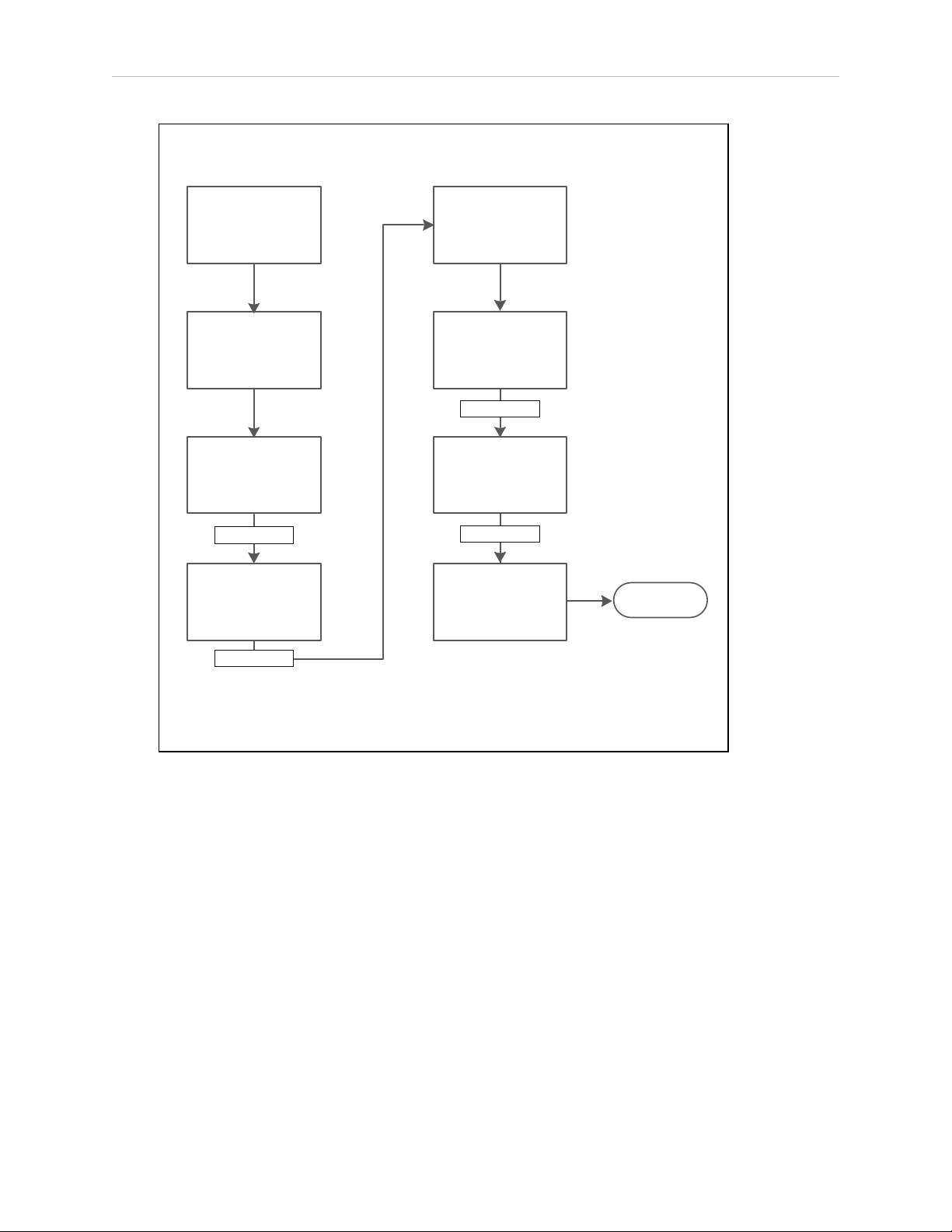
6.3 Managing Queuing
Automated, Single-stop Queuing Sequence
WMS, MES, or other
custom application
requests AIV
for pickup
Manager selects
an AIV, and
sends it to the
desired location
AIV stops
at desired location
Payload
gets loaded
AIV goes
to the unloading
location
Payload gets
unloaded
AIV stops at
unloading location
Handshake
Handshake
Handshake
Handshake
Handshake refers to some form of communication between the AIV and
the automated factory equipment.
The form of this handshake will vary, depending on the equipment in use.
AIV sent to default
location or freed
up for new jobs
COMPLETE
Queuing Parameters
You configure various parameters to specify how the Enterprise Manager 2100 processes
queued requests. You set most of these parameters from within MobilePlanner. See the Mobile
Robot Software Suite User's Guide for information about using the MobilePlanner software.
To access these parameters from Enterprise Manager 2100:
The parameters that control the way that the Enterprise Manager 2100 handles queuing are:
Figure 6-2. Fully-automated Queuing Cycle
1.
In MobilePlanner, open the Config tab.
2.
Select Robot Operation and then Queuing Manager.
l
IdleTimeUntilResume - Number of minutes to wait, after an AIV becomes available,
before automatically resuming an interrupted job.
68 Enterprise Manager 2100 User’s Guide 14413-200 Rev. A
Page 69

Chapter 6: Operation
If an AIV has recently booted , or recently operated manually, then this is the number of
minutes that the queuing manager waits before assigning any new jobs to this AIV. The
parameter supports decimal numbers (such as 0.1 minutes for 6 seconds).
l
LowStateOfCharge - This is the state-of-charge (SOC) below which the queuing manager no longer assigns new jobs to that AIV. If an AIV is below this state of charge
when it completes a job, it is sent to dock.
The AIV continues its assigned jobs until it reaches the SOC limit set by the value of the
AutoDockStateOfCharge parameter. Consider the following constraints:
o
An AIV drives to a docking station any time that its state of charge falls below
the limit set for AutoDockStateOfCharge even if it is performing a job. This is an
AIV-level parameter, not visible or settable on the Enterprise Manager 2100.
o
Omron Adept Technologies, Inc.recommends that at least a 10% difference
between LowStateOfCharge and AutoDockStateOfCharge, to make sure that the
AIV does not drive to a docking station while performing a job.
o
An AIV docks only if you set AutoDock to True.
l
DefaultDropoffPriority - The default priority to use in all dropoff requests to the
queuing manager.
l
DefaultPickupPriority - The default priority to use in all pickup requests to the queuing
manager.
l
DeleteCompletedItemsMinutes - Number of minutes to keep completed jobs.
l
MaxNumberOfCompletedItems - Maximum number of completed jobs to keep.
l
EnableParking - Sends the AIV to a standby goal after it completes its jobs.
14413-200 Rev. A Enterprise Manager 2100 User’s Guide 69
Page 70

6.3 Managing Queuing
The following screen shows configuration parameters for queuing:
Figure 6-3. Queuing Manager Parameters
The following list shows the commands available for queuing.
l
CancelQueueId
l
CancelQueueJobId
l
DisplayDeliveryQueue - Presents a pop-up window showing the delivery queue.
l
DisplayShowRobot - Presents a pop-up window that shows the status of all AIVs in the
fleet.
l
QueuingLog
l
QueuingStats
To find these parameters in MobilePlanner, click Config and Robot Operation and then
Queuing Manager.
NOTE: A red plus sign (+) preceding a command indicates that it accepts an
argument.
Manually Clearing (Flushing) the Entire Queue
Use the ARAMCentral software to set the configuration parameters that apply to your fleet.For
some parameters, you must also make corresponding changes to the configuration on the individual AIVs. Use ARAMCentral parameters only in limited circumstances, typically when
working with your local Omron support.
To clear the entire queue, temporarily add a special startup argument to ARAMCentral. The following procedure clears the queue:
1.
In MobilePlanner select the Config tab.
2. Select Enterprise and then Enterprise Config Management.
3.
Under SectionsToSeparate, increment Count if there are no empty SeparateSectionX
rows, where ‘X’ is a number, with an empty Value fields.
4.
Enter the string "EnterpriseManagerFlush" in an empty Value field.
70 Enterprise Manager 2100 User’s Guide 14413-200 Rev. A
Page 71

5.
Click Save.
6.
Wait for the ARAMCentral software to restart.
7.
Use the command in MobilePlanner to verify that the queue is cleared.
a.
Select EnterpriseManagerDisplayDeliveryQueue from the Command field dropdown list.
b.
Click the Command icon.
The queue should now be empty.
8.
Reconnect to the MobilePlanner software, and remove the "EnterpriseManagerFlush"
entry.
9.
Click Save.
10.
Wait for the ARAMCentral software to restart.
6.4 Update the ARAMCentral Software
You can update the ARAMCentral version on the Enterprise Manager appliance from within
SetNetGo. This is part of the Mobile Software suite.
Chapter 6: Operation
To update the ARAMCentral package:
1.
Open SetNetGo.
2.
Select Software and then Manage Installed Software.
3.
Click Browse... to navigate to and select the software update file.
4.
Click Upload to upload the Mobile Software suite to the Enterprise Manager appliance.
This uploads the ARAMCentral software.
Use the View Release Notes option to see changes and features that are included in the
update.
Restarting ARAMCentral
Changes to the Enterprise Manager appliance ARAMCentral might cause it to automatically
stop and restart (depending on the type of change that you make). You can also use SetNetGo
to force ARAMCentral to restart as follows:
1.
Open SetNetGo.
2.
Select Software and then Manage Installed Software.
3.
Click Restart.
6.5 Enterprise Manager 2100 Autosync Operation
Autosync provides operational redundancy if a problem occurs with the Primary appliance.
During normal Autosync operation, you will observe changes only when either the Primary or
Secondary appliance stops operating. This might be caused by a temporary power loss or an
14413-200 Rev. A Enterprise Manager 2100 User’s Guide 71
Page 72

6.6 Remove and Replace Enterprise Manager 2100 Appliances from Autosync
internal hardware component failure such as a disk drive crash. If both appliances are
affected, all fleet operations terminate.
NOTE: The Enterprise Manager 2100 appliance contains no user-serviceable
components. Contact your local Omron support if a catastrophic hardware failure occurs. See: How to Get Help on page 15.
6.6 Remove and Replace Enterprise Manager 2100 Appliances from Autosync
This section describes how to remove an appliance from an Autosync configuration.
Remove a Primary Appliance from Autosync
You might need to remove a Primary appliance from an Autosync configuration while maintaining fleet operations. For example, if the Primary appliance is generating errors that indicate
a potential failure or degraded performance. This procedure assumes that you do not make
any changes to the software and data stored on the removed appliance.
To safely remove an Enterprise Manager 2100 Primary appliance from an Autosync configuration, you must promote the Secondary appliance to the Primary role as shown in 6.6
You can then safely remove the Primary as follows:
1.
Verify that fleet operations are normal and job processing is on schedule.
2.
Reconfigure the Primary appliance as a Secondary appliance. See: Configure the Secondary Appliance on page 57.
MobilePlanner and fleet AIVs might lose their network connection to the appliance.
3.
Reconfigure the Secondary appliance [2] as the Primary appliance. See: Configure the
Primary Appliance on page 56.
4.
Power off the Secondary (failing) appliance.
5.
The new Primary appliance now indicates that Autosync is disabled (it is now a standalone appliance.)
6.
Verify that MobilePlanner can connect to the Fleet IP, that fleet AIV operations resume,
and jobs are processed as scheduled.
To restore a removed appliance to its role as Primary appliance, or to replace it with a new
appliance:
1.
Verify that fleet operations are normal and job processing is on schedule.
2.
If you have removed any network cables, replace them as shown in Figure 5-5.
3. Power on the (now Secondary) appliance. (This should not affect fleet operations or Ethernet connections to MobilePlanner and AIVs.)
4.
Reconfigure the Primary appliance as a Secondary appliance. See: Configure the Secondary Appliance on page 57.
MobilePlanner and fleet AIVs might lose their network connection to the appliance.
72 Enterprise Manager 2100 User’s Guide 14413-200 Rev. A
Page 73

Chapter 6: Operation
5.
Reconfigure the Secondary appliance as the Primary appliance. See: Configure the
Primary Appliance on page 56.
6.
Both appliances now indicate that Autosync is Active.
7.
Verify that MobilePlanner can connect to the Fleet IP, that fleet AIV operations resume,
and jobs are processed as scheduled.
Remove a Secondary Appliance from Autosync
You might need to remove a Secondary appliance from an Autosync configuration while maintaining fleet operations. For example, if the Secondary appliance is generating errors that indicate a potential failure or degraded performance. This operation is less disruptive than
removing a Primary appliance.
IMPORTANT: This procedure assumes that you do not make any changes to
the appliance configuration or to the software and data stored on the appliance.
To remove an Enterprise Manager 2100 Secondary appliance from an Autosync configuration:
1.
Verify that fleet operations are normal and job processing is on schedule.
2.
Power off the Secondary appliance.
3.
The Primary appliance now indicates that Autosync is disabled (it is now a standalone
appliance.)
4.
Verify that MobilePlanner can connect to the Fleet IP, that fleet AIV operations resume,
and jobs are processed as scheduled.
To restore a removed Secondary appliance:
1.
Verify that fleet operations are normal and job processing is on schedule.
2.
If you have removed any network cables, replace them as shown in Figure 5-5.
3. Power on the Secondary appliance. (This should not affect fleet operations or Ethernet
connections to MobilePlanner and AIVs.)
Both appliances now indicate that Autosync is Active.
4.
Verify that MobilePlanner can connect to the Fleet IP, that fleet AIV operations resume,
and jobs are processed as scheduled.
14413-200 Rev. A Enterprise Manager 2100 User’s Guide 73
Page 74

6.7 What to do if an EM2100 Primary Appliance Fails
6.7 What to do if an EM2100 Primary Appliance Fails
This section applies only if you installed a Secondary Enterprise Manager appliance, autosynchronized with the Primary.
In event of failure:
1.
Using the SetNetGo interface, connect to the Management IP address for the Secondary
appliance.
2.
From SetNetGo on the Secondary appliance, select Software and then Autosync.
3.
Switch the Secondary appliance from Secondary to Primary.
Use the drop-down arrow in the Autosync role field to select Primary.
4.
Click Apply or click Reset to clear the form and restore its original values.
The AIVs automatically reconnect to the new Primary appliance.
The queue, configuration, and map data on the new Primary is identical to that of the old
Primary, prior to failure. Depending on exact network configuration, it takes between 1-3
minutes for AIVs to reconnect and resume operation.
The original (failed) Primary appliance can now be safely removed from the rack without causing disruption to the fleet. The following considerations apply:
l
The new Primary operates on the same Fleet IP as the old Primary appliance. Do not
reconnect the old Primary to the network without first reconfiguring it. Doing so might
cause a network IP conflict.
l
The failed Primary has the queue file, which is no longer current. Before putting the
failed Primary back into service, you should manually clear the queue. See Manually
Clearing (Flushing) the Entire Queue on page 70.
6.8 What to do if an EM1100 Autosync Appliance Fails
This section applies only if you have a two EM1100 appliances in an Autosync configuration,
and either the Primary or the Secondary fails and you must replace it with an EM2100. In
mixed-model configurations, the EM2100 always operates as the Primary appliance, while the
EM1100 always operates as the Secondary appliance.
If you have a mixed-model (EM1100 + EM2100) Autosync configuration, it cannot support
multiple software versions. Both appliances must run the same version that is running on an
EM2100, and you must upgrade the EM1100 to that version.
Configure an EM1100 to EM2100 Configuration
Use the following procedure to replace a failed EM1100 Appliance with a replacement
EM2100.
1.
Power off the failed appliance and disconnect its power cable.
2.
Remove the networking cables from the failed EM1100 appliance and physically
remove it.
74 Enterprise Manager 2100 User’s Guide 14413-200 Rev. A
Page 75

Chapter 6: Operation
3.
Install the replacement EM2100 hardware as described in: Installation on page 21.
4.
Reconnect the networking cables from the remaining, functioning EM1100 as shown in:
EM2100 and EM1100 Autosync — Ethernet Cabling on page 55.
5.
Using the SetNetGo interface, connect to the EM1100 Management IP address.
6.
Update the software on the EM1100 as described in: Update the ARAMCentral Software
on page 71.
7.
From SetNetGo on the Secondary appliance, select Software and then Autosync.
8.
If the EM1100 is not already configured as a Secondary appliance, configure it as
described in: Configure the Secondary Appliance on page 57.
9.
Configure the replacement EM2100 as the Primary appliance as described in: Configure
the Primary Appliance on page 56. If not already configured as a Primary, which is the
default (shipped) setting.
10.
Wait for Autosync to start and for normal operation to resume.
The AIVs automatically reconnect to the new Primary appliance.
The queue, configuration, and map data on the new Primary is identical to that of the old
Primary, prior to failure. Depending on exact network configuration, it takes between 1-3
minutes for AIVs to reconnect and resume operation.
You can now safely remove the original (failed) Primary appliance from the rack without causing disruption to the fleet. The following considerations apply:
l
The new Primary operates on the same Fleet IP as the old Primary appliance. Do not
reconnect the old Primary to the network without first reconfiguring it. Doing so might
cause a network IP conflict.
l The failed Primary has the queue file, which is no longer current. Before putting the
failed Primary back into service, you should manually clear the queue. See Manually
Clearing (Flushing) the Entire Queue on page 70.
14413-200 Rev. A Enterprise Manager 2100 User’s Guide 75
Page 76

6.9 Troubleshooting
6.9 Troubleshooting
Use SetNetGo or the command prompt in your Windows client PCto do the following.
Symptom
No Power LED
Check power
source
Maintenance network unavailable
ping IP 1.2.3.4
Management network unavailable
ping the Management IP address
Fleet network
unavailable
ping the Fleet IP
address
Possible
Causes
Power or
hardware
failure
Network
failure
OS image
failure
LAN
configuration
error
LAN
configuration
error
Network
cabling error
Autosync
configuration
error
Possible Remedies
Verify power cord plugged into working outlet or functional UPS
Verify power switch on back of EM is in the ON position
Contact your local Omron support
Verify PC network settings
Verify cable, plugged into MAINT port
Contact your local Omron support
Verify the Management Interfacesettings in
SetNetGo
Verify firewall access across
network
Verify network cable plugged
into LAN from MGMT port
Verify firewall access across network
Single EM (no Autosync):
l Verify autosync mode set to Primary
l Verify proper “Fleet Interface” settings in
SetNetGo
l Verify the Ethernet cable connections
With Autosync:
l Verify proper “Fleet Interface” settings on
Primary unit in SetNetGo
l Verify Autosync mode set to Primary on one
EM, and Secondary on the other EM
l Verify Ethernet cable connections
Fleet network available, but not functional
ARAMCentral
configuration
error
Network permissions
error
Autosync
configuration
Verify that the Fleet IP address is different than the
Management IP address
Verify ARAMCentral is running by checking logs in
SetNetGo
Verify firewall access
If using Autosync, verify autosync mode is set to
Primary on only one Enterprise Manager
error
76 Enterprise Manager 2100 User’s Guide 14413-200 Rev. A
Page 77

Chapter 6: Operation
Symptom
Cannot connect to
ARCL port
Can connect with
ARCL to Fleet IP
address
No AIVs appear in
MobilePlanner
Possible
Causes
ARAMCentral
configuration
error
License key
error
Configuration
error on AIV
WiFi network
permissions
error
Software
version
mismatch
Possible Remedies
Verify ARCL Server is enabled
Verify firewall access
Verify AIVs are configured with “ConnectToEnterpriseManager” and related parameters.
Verify AIVs are set up on WiFi.
Verify AIVs have firewall
access to access Enterprise Manager appliance
from WiFi network
Verify AIVs are running same MAJOR.MINOR version of
software as EM. For best results, install the same
Mobile Software suite on all EMs and AIVs.
If you are requesting help from Omron Adept Technologies, Inc., it is very useful to include a
debugInfo file. Instructions for doing so follow.
Including a debugInfo File with Your Help Request
Use the MobilePlanner SetNetGo interface to retrieve the debugInfo file.
If you are unable to use the MobilePlanner SetNetGo interface:
1.
Open a web browser and enter the URL:
https://<your_EnterpriseManager_IP>
If you have not set up the Enterprise Manager appliance on the main LAN, then make a
direct connection from your PC to the MAINTETHport.
2.
Set the IP address to: 1.2.3.5 and the Subnet Mask to: 255.255.255.0.
3.
Using a network patch cable (straight-through), connect the network port of your computer to AIV's maintenance port (MAINTETH).
4.
Open a web browser and enter the URL: https://1.2.3.4
In either case, you are requested to confirm security certificates. You should now have the
SetNetGo Home window.
14413-200 Rev. A Enterprise Manager 2100 User’s Guide 77
Page 78
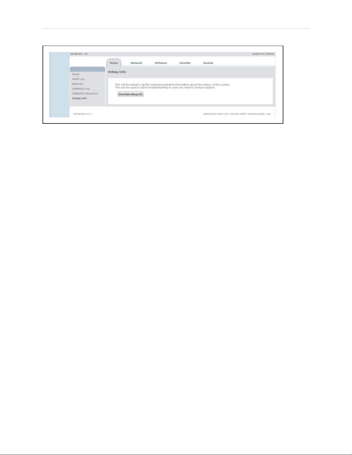
6.9 Troubleshooting
1.
Select Status and then Debug Info.
2.
Click Download debug info.
3.
Save the file, and attach it to your support request.
78 Enterprise Manager 2100 User’s Guide 14413-200 Rev. A
Page 79

Chapter 7: Technical Specifications
This chapter provides the technical specifications and physical dimensions of the Enterprise
Manager appliance.
7.1 Processing Specifications
Table 7-1. Processing Specifications
CPU Intel®Xeon®CPU
Memory 32 GB DDR3
Operating System SetNetGo Embedded LINUX
Data Storage 4 TB
7.2 Environmental Specifications
You must ship or store the Enterprise Manager appliance under environmentally-controlled
conditions. Refer to the following table.
Table 7-2. Environmental Specifications
Operating temperature 10 to 35°C (50 to 95°F)
Operating humidity range 8 to 90%, non-condensing
Storage and shipment temperature –25 to +60°C (–13 to +140°F)
Storage and shipment humidity range 5 to 95%, non-condensing
Chassis protection class IP20 (NEMA Type 1)
7.3 Power Requirements
Input Voltage 100 - 240 VAC, 50/60 Hz
Typical Power Consumption 100 W
Maximum Power Consumption 200 W
Appliance power inlet connector IEC 60320 C14 (Maximum 15 A, 250 V)
Table 7-3. Power Specifications
14413-200 Rev. A Enterprise Manager 2100 User’s Guide 79
Page 80

7.4 Physical Characteristics
2
1
3
4
KEYOUT
Cat 5eCat 5eCat 5e
MGMTMAINT
Cat 5e
FLEET PORTS
IN
ENTERPRISE MANAGER 2100
PWR
SYS
HDD
5
6
7
8
9 10
7.4 Physical Characteristics
The Enterprise Manager appliance is a standard 1U rackmount.
Figure 7-1. Dimensions
Table 7-4. Physical Characteristics
Chassis enclosure depth 1 49.27 cm 19.40 inches
Pull handle depth 2 2.92 cm 1.15 inches
Chassis and bracket depth 3 49.53 cm 19.50 inches
Rail kit hole spacing 4 9.22 cm 3.63 inches
Rail kit hole offset (from bracket) 5 10.44 cm 4.11 inches
Max system width 6 48.26 cm 19.00 inches
Securing hole spacing 7 45.55 cm 18.33 inches
80 Enterprise Manager 2100 User’s Guide 14413-200 Rev. A
Characteristic Callout Metric US
Page 81

Chapter 7: Technical Specifications
Characteristic Callout Metric US
Chassis enclosure width 8 43.00 cm 16.93 inches
Chassis height (1U) 9 4.36 cm 1.72 inches
Securing hole spacing depth 10 3.18 cm 1.25 inches
Appliance weight n/a 13.43 kg 29.6 lbs
Shipping dimensions
7.5 Connections
Front
l
10/100/1000 Ethernet x 4
l
USB for service use
Rear
l
USB x 4 for service use
l
VGA (HDB15F) for service use
l
IEC ACPower inlet
n/a
76 x 65.1 x 19.7
(cm)
30 x 25.625 x 7.75
(inches)
14413-200 Rev. A Enterprise Manager 2100 User’s Guide 81
Page 82

Page 83

1U 80
24 VDC power
connecting 33
specifications 33
AC Power inlet 81
access
fleet 48
SetNetGo 47
Index
1
2
A
account 48
Admin 48
MobilerPlanner 48
Operator 48
User 48
viewer 48
active 39, 57
Administrator 48
Advanced Robotics Automation Management 13
Advanced Robotics Command Language 14-15
AIV 8, 64
assigned job 64
configuration 54
connecting to appliance 52
customizing 57
jobs 10, 64
14413-200 Rev. A Enterprise Manager 2100 User’s Guide 83
Page 84

number supported 9
required 64
safety 15
alert 17
appliance 12
autosync 72
failed 14-15
remove 72
ARAM 13
ARAMCentral 13, 71
update 71
ARCL 14-15
server 52
assigned job 64
auto-synchronize 11
Automated Intelligent Vehicles 7
automation
call button 59
system 14
autonomous 13
Autosync 14-15, 39
configure 54
operation 71
remove appliance 72
status 39, 57
boot errors 61
B
84 Enterprise Manager 2100 User’s Guide 14413-200 Rev. A
Page 85

cabling
Ethernet 54
call button 59
chassis 80
clear
queue 70
client PC
Set IP 47
clock 51
configuration 7, 11, 45
AIV 54
overview 45
configure
C
AIV 52
Autosync 54
fleet interface 50
management interface 50
network 49
secondary appliance 54
SetNetGo 47
connect to SetNetGo 47
connecting
AIV 52
network 40
power 33
connections 45
network 40
connectors and indicators 37
14413-200 Rev. A Enterprise Manager 2100 User’s Guide 85
Page 86

controls 37
copyright 2
Customer Service assistance 15
customize AIV 57
date and time 51
debugInfo 77
dimensions and specifications 80
disabled 39
display panel 37, 39, 61
Disposal 20
dock 57
preferred 58
separate 58
D
docking station 10, 57
domain server 50
download map 64
dropoff 64
DSN 50
dynamic route adjustments 11
error
information 37
log 77
Ethernet
cabling 54
connections 40
port 39
E
status 39
86 Enterprise Manager 2100 User’s Guide 14413-200 Rev. A
Page 87

failed 39
failed primary appliance 14-15
failed secondary appliance 15
fans 38
FIFO 10
firewall 76
fleet 11
access 48
Ethernet 38
interface 50
MobilePlanner settings 53
FLEET (ETH2) 56
Fleet administrative port 40
F
FLEET PORTS IN 56
flush queue 70
front power switch 39
gateway 49
generate a map 64
hard shutdown 62
hard stop 38
hazard 17
heartbeat 54
help 15, 77
How Can I Get Help? 15
G
H
14413-200 Rev. A Enterprise Manager 2100 User’s Guide 87
Page 88

id
queud 65
IEC 81
indicators 37
installation 15
Installation 21
IP
client PC 47
job 10-11, 13, 64
assigned 64
dropoff 64
pickup 64
I
J
queue 64
required AIV 64
segment 64-65
states 66
LAN 8, 10
LCD 39
LED 38
power 61
license 10, 13
dongle 13
key 11
log
error 77
L
88 Enterprise Manager 2100 User’s Guide 14413-200 Rev. A
Page 89

mains power switch 39
maintenance 15
Ethernet 38
port 40, 45
management
Ethernet 38
interface 50
port 40
managing queuing 64
Managing Queuing 64
Manuals 15
Manufacturing Execution System 10
map 9, 13
M
downloading 64
features 9
generating 64
workspace 64
MARC 13
firmware 14
MES 8, 11, 52
MGMT 56
mixed mode 58
mobile robots 11
Mobile Software
suite 14
MobilePlanner 13-14, 45, 48
access 48
ARCL 52
14413-200 Rev. A Enterprise Manager 2100 User’s Guide 89
Page 90

fleet settings 53
Operator Mode 13
network 40
bandwidth 11
connecting to 40
gateway 49
settings 49
switches 11
troubleshooting 76
Network Time Protocol 51
notice, copyright 2
NTP 51
N
Operation 61
operator 48
options 45, 54
overview
configuration 45
em2100 37
password 47
ARCL 52
payload 10
PC client 11
pending job queue 54
peripherals 15, 59
O
P
permissions 48
90 Enterprise Manager 2100 User’s Guide 14413-200 Rev. A
Page 91

pickup 64
ports
connections 40
Ethernet 39
power
cable 10
LED 61
nput 39
off 61
on 61
supply 38
switch 37, 61
preferred dock 58
primary 15
appliance 11, 14, 54
primary appliance
failed 14-15
queue 64
flushing 70
id 65
managing 64
parameters 68
queuing 13
queuing manager 7, 11
rack-mount 10, 19
Q
R
rail kit 19, 80
RAM 10
14413-200 Rev. A Enterprise Manager 2100 User’s Guide 91
Page 92

rear panel 38
recharging 57
Release Notes 12
Remote I/O 13
remove appliance 72
required robot 64
restart 37
robot 7
fleet management 12
required 64
safe power on 61
safety 15, 17
secondary 15
S
appliance 11, 14
configure 54
secondary appliance 54
failed 15
security 47
segment 65
separate dock 58
service 16, 38
SetNetGo 12, 45
access 47
connecting 47
security 47
settings
fleet 53
network 49
92 Enterprise Manager 2100 User’s Guide 14413-200 Rev. A
Page 93

shipping dimensions 81
shut down 61
hard 62
software update 71
specifications 79
24 VDC power 79
CPU 79
dimensions 80
hard drive 79
memory 79
processing 79
speech synthesis 58
SSL key 56
startup 39
status 37
autosync 39, 57
Autosync 39
Ethernet 39
jobs 66
panel 39
queue 66
status display panel 39
storage 10, 38
support 16, 77
support, contact information 15
SVGA 38
switch
power 61
synchronize ethernet 38
14413-200 Rev. A Enterprise Manager 2100 User’s Guide 93
Page 94

system
clock 51
specifications 15
technical support 77
time 51
touchscreen 14
troubleshooting 76
turn off power 61
turn on power 61
uninterruptable power supply 11
unpacking 24
T
U
update software 71
UPS 11
USB 12, 38, 81
user 48
VGA 81
viewer 48
voice 58
warehouse management system 10
Web management interface 47
WEEE 20
WiFi 8
V
W
Windows client PC 12, 47
94 Enterprise Manager 2100 User’s Guide 14413-200 Rev. A
Page 95

wireless 13
bandwidth 10, 12
Ethernet 12
WMS 8, 10-11, 52
workspace 9, 13
map 54, 64
14413-200 Rev. A Enterprise Manager 2100 User’s Guide 95
Page 96

OMRON Corporation Industrial Automation Company
Kyoto, JAPAN
Regional Headquarters
OMRON EUROPE B.V.
Wegalaan 67-69, 2132 JD Hoofddorp
The Netherlands
Tel: (31)2356-81-300/Fax: (31)2356-81-388
OMRON ASIA PACIFIC PTE. LTD.
No. 438A Alexandra Road # 05-05/08 (Lobby 2),
Alexandra Technopark,
Singapore 119967
Tel: (65) 6835-3011/Fax: (65) 6835-2711
Contact: www.ia.omron.com
OMRON ELECTRONICS LLC
2895 Greenspoint Parkway, Suite 200 Hoffman Estates,
IL 60169 U.S.A.
Tel: (1) 847-843-7900/Fax: (1) 847-843-7787
OMRON ADEPT TECHNOLOGIES, INC.
4550 Norris Canyon Road, Suite 150, San Ramon, CA 94583 U.S.A.
Tel: (1) 925-245-3400/Fax: (1) 925-960-0590
OMRON (CHINA) CO., LTD.
Room 2211, Bank of China Tower, 200 Yin Cheng Zhong Road,
PuDong New Area, Shanghai, 200120, China
Tel: (86) 21-5037-2222/Fax: (86) 21-5037-2200
Authorized Distributor:
© OMRON Corporation 2019 All Rights Reserved.
In the interest of product improvement,
specifications are subject to change without notice.
Cat. No. I631-E-01
Printed in USA
0119
14413-200 A
 Loading...