

Omron EN 60947, IEC 947 DATASHEET

Low Voltage Switch Gear
Appendix
Precautions
■ Notice
Use under rated condition, otherwise contactors will not only cause
malfunction, but also cause a fire or damage the contactor.
Life period of contactor depends on the operating application. Please
check the electrical life under real application in advance.
If you continue to use malfunctioning contactor, a fire or breakdown
may occur.
Do not miss-wire or miss-charge the power supply, otherwise the
contactor does not work correctly.
Do not operate in places with explosive or flammable gas, otherwise
a fire or explosion may occur by arc or heating from contactor.
Make sure to use the circuit well considered about safety, in case
there is any possibility to cause secondary disaster by contact trouble (welding, faulty contact).
Do not supply short-circuit current to electromagnetic switch (contactor with thermal relay). Doing so may result failure in heater of thermal relay. Please use short-circuit protection like fuse or protective
circuit breaker.
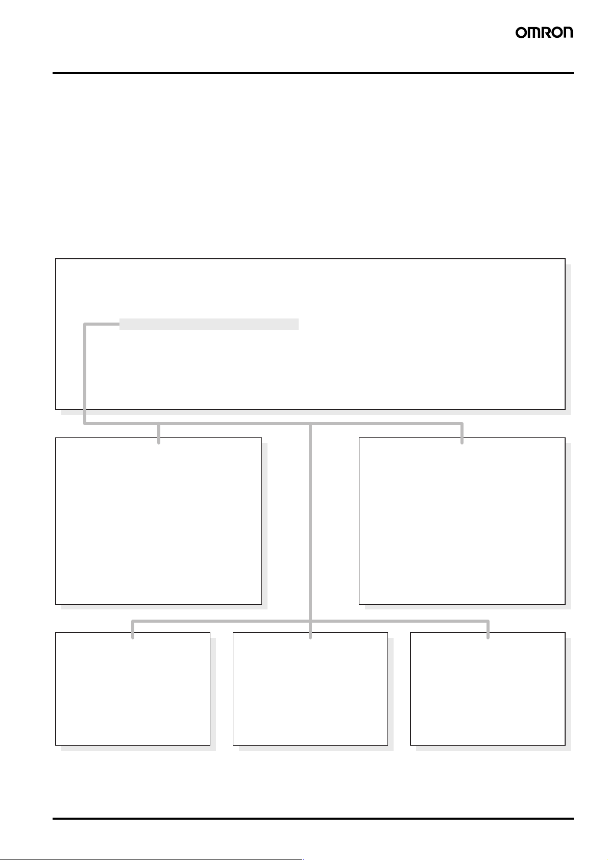
■ Correct use
General use
Unexpected malfunction may occur in real application. Please carry
out as many tests as possible.
Ratings in this catalogue measured under the condition according to
IEC unless otherwise specified. In cases of check by real application,
please carry out the test under the same condition as expected in the
actual application.
Selection
Coil specification
Please select suitable coil to circuit design, otherwise malfunction
may occur or coil may have a burn out by overvoltage etc.
Type
Please check contact ratings, switching capacity, thermal characteristics etc. when selecting product type.
Thermal relay
Motor current differs by supplier, type, number of poles, frequency.
Please confirm operational current level.
Coil surge suppressor
Coil surge suppressor type should be selected by contactor type,
auxiliary relay type and applied voltage. Make sure to use defined
each contactor.
In case of installing coil surge suppressor, please check the actual
circuit because the release time will be delayed.
Electrical life expectancy
Electrical life expectancy tests in this catalogue are based on IEC.
Do not use a contactor or thermal relay which has been dropped or
dismantled. Doing so may cause malfunction or a fire.
Make sure to shut off power supply to contactors before wiring or
replacing.
Do not operate the actuator of a contactor manually. Doing so may
cause contact welding by chattering or burn out by arc.
Unless otherwise stated in the catalogue,
modifications, especially those of stated values,
sizes and weights are subject to alternation.
Diagrams and tables are subject to alternation and
not to be regarded as binding drawings.
Circuit design
Supplied voltage waveform for input
Make sure to apply and remove the voltage instantly. Do not use
under the condition that the coil voltage waveform increases or
decreases gradually.
In case of DC contactor use (input voltage
ripple)
Please use DC contactor input voltage with a ripple ratio less than
5%. Excessive ripple (pulsating current) may cause contact welding.
Fluctuation of input voltage
Make sure to supply sufficient voltage to actuate contactors properly.
Continuous supply of insufficient voltage results in excessive heating
and may cause burn out of coil.
Maximum applied voltage
Do not supply the voltage over the maximum rated voltage, otherwise
burn out or insulation failure may occur.
The temperature inside control panel has much influence to the coil
temperature, so make sure not to exceed the specified value in the
catalogue.
Basically rated voltage should be supplied to coil. To supply higher
voltage than rated would result in shorter electrical life, even if it is
lower than the maximum rated voltage.
Reverse
Make sure to use reversible contactors for reverse operation.
Make sure to use interlock device in reverse operation by two contactors, otherwise short circuit current may burn out or give damage to
contactors and motors.
Low Voltage Switch Gear Appendix 81

Installation
Operation ambience
Mounting
Make sure to use specified wire size, mounting screw size, mounting
screw number, and DIN rail size.
Tightening Screw
Tighten each screw securely by specified tightening torque. Loose
tightening may cause a fire by excessive heating.
Combination
Please use only OMRON product combinations in case of thermal
relay, timer block and auxiliary contact block etc.
Wrong-combinations may result in damage to contactors.
Mounting direction
Some products have a defined specific mounting direction. Please
refer to datasheet before use.
Dust
Dust on the surface of the contacts could result in contact malfunctioning. Take countermeasure in excessive dusty surrounding.
Temperature, humidity
Use contactors within the temperature and humidity conditions specified in datasheet. To use or store contactor in excessive temperature
or humidity may result in malfunction of contact by organic film composed by sulfication and oxidation on the surface of the contacts.
Use contactors within the temperature and humidity conditions specified in the datasheet, to prevent contactors from insulation resistance failure by condensation or insulation resistance deterioration
by tracking.
Gas
NH3, H2S, SO2, CI2, Si and NO2 have bad effects on a contactor.
With these gases, a corrosive metal film ist generated on the surface
of the contacts and could result in contact malfunctioning. Use a contactor in low humidity and no corrosive gas surroundings.
Oil
Do not use a contactor in places where oil is sprayed onto the contactor. It will cause cracks on polymer parts.
Shock and vibration
Do not use a contactor in places where there is excessive shock or
vibration. It may cause malfunctioning.
Storage
Store contactors in a place with no direct sunshine or ultraviolet rays.
It will cause crack on polymer parts.
When contactors are to be stored for a long time, they must be stored
with care. Though it generally depends where contactors are stored,
deterioration of contacts may occur after long storage. Please check
the characteristics before use after long time storage.
82 Low Voltage Switch Gear Appendix
European Standards
■ IEC 947, EN 60947
European Standards for Low-Voltage Switchgear
For Europe and most other industrial countries of the world, the new
IEC 947 and EN 60 947 specifications for low-voltage switchgear
have unified the regulations which previously varied from nation to
nation.
This required the introduction of new terms, and new test methods
and utilization categories. The new specifications are aimed
primarily at manufacturers. However, the user also will come across
new technical terms and data in the manufacturers’ catalogues
and on the devices themselves which are important for the selection
and application of the devices. The present paper deals with the currently published specifications. Further specifications and
supplements are in preparation.
IEC 947
IEC 947-1 General rules
IEC 947-2 Circuit-breakers
IEC 947-3 Switches, disconnectors, switch-disconnectors and fuse-combination units
IEC 947-4-1 Connectors and motor-starters
IEC 947-5-1 Control circuit devices and switching elements
IEC 947-6-1 Multiple function equipment, Automatic transfer switching equipment
IEC 947-6-2 Multiple function equipment, Control and protective switching devices (or equipment)
(CPS)
IEC 947-7-1 Ancillary equipment
Since 1993, all low-voltage switchgear purchased in Europe had to
satisfy the EN 60 947 European Standard. Installations in existence
prior to 1993 are not affected by the standard and need not to be
refitted with new devices. Devices constructed and tested to the IEC
standards and EN standards can be used worldwide, with the exception of the USA and Canada. In these countries UL and CSA specifications continue to apply. Switchgear which conforms to IEC 947
and EN 60 947 and which has, in addition, UL- and CSA approvals,
in the meantime has entered the market. Such ‘world market’ devices
offer the advantage that they can be used throughout the world,
including the USA and Canada.
Conditions for compliance with
Type "1" coordination
(Extract from IEC 947-4-1)
- The contactor or the starter must not endanger
personnel or equipment in the event of a short
circuit
- The contactor or the starter does not need to be
suitable for continued operation without repair and
replacement of parts
- Damage to the contactor and the overload relay is
permissible
Rated conditional
short-circuit current l
- The rated conditional short-circuit
current l
circuit breaking capacity of the starter
indicates the max. short-
q
q
Rated operation current l
- The rated operational current le for
the starter is the current when the
starter is in the On position
Conditions for compliance with
Type "2" coordination
(Extract from IEC 947-4-1)
- The contactor or the starter must not endanger
personnel or equipment in the event of a short
circuit
- The contactor or the starter must be suitable for
further use
- No damage may occur to the overload relay or
other parts, with the exception of welding of the
contactor or starter contacts, provided they can
be separated easily without any significant
deformation (e.g. using a screwdriver)
e
Rated uninterrupted current l
(to IEC 947-1)
- The rated uninterrupted current lu of
a unit is a current, specified by the
manufacturer, which the unit can
carry without interruption
u
Low Voltage Switch Gear Appendix 83
Overview
The following table shows in summarized form both the previous and the new IEC, EN and DIN VDE standards.
Previous specification New specification
EN 60947
DIN VDE
- - 947-1 60947-1
157 0660, Part 101 947-2 60947-2
406 0660, Part 107 947-3 60947-3
158
292-1
292-2
292-3
337 0660 Part 200 to Part 205 947-5-1 60947-5-1
- - 947-6-1 60947-6-1
- 0611 Part 1 and 2 947-7-1 60947-7-1
0660, Part 102
0660, Part 104
0660, Part 106
0660, Part 301
947-4-1 60947-4-1
0660, Part 100
0660, Part 101
0660, Part 107
0660, Part 102
0660, Part 200
0660, Part 114
0611, Part 1
ContentIEC DIN VDE IEC
Low-voltage switchgear,
General rules
Low-voltage switchgear,
Circuit-breakers
Low-voltage switchgear,
Switches,
Disconnectors,
Switch-disconnectors,
Fuse-combination units
Low-voltage switchgear,
Control circuit devices and switching elements
Low-voltage switchgear,
Multiple-function equipment,
Automatic transfer switching equipment
Low-voltage switchgear,
Multiple-function equipment,
Control and protective switching devices (CPS)
Low-voltage switchgear,
Ancillary equipment (e.g. terminal blocks)
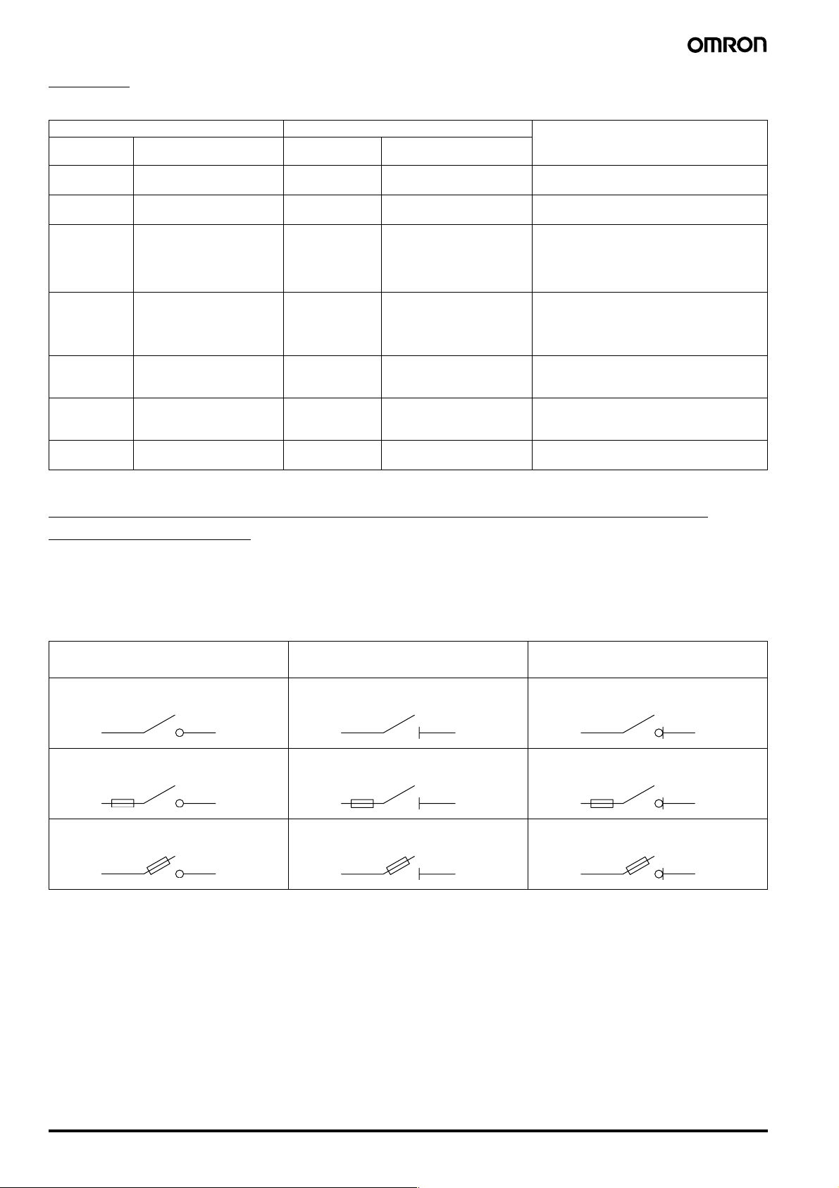
Switches, disconnectors, switch-disconnectors and fuse combination units
(IEC 947-3, EN 60947-3)
These devices must now be labelled with the product function designated by the manufacturer. This means placing clearly visible symbols on the
device itself.
Devices with an isolating function are subject to special safety requirements. They must for example have greater creepage distances and clearances across the opened contacts than is necessary for other devices.
Device functions and corresponding symbols
Making/breaking Isolating
Switch Disconnector Switch-disconnector
Switch-fuse Disconnector-fuse Switch-disconnector-fuse
Fuse-switch Fuse-disconnector Fuse switch-disconnector
Making/breaking
+ isolating
OMRON equipment is designed for the world’s markets
It is manufactured and tested in accordance with national and international specifications, the most important of which are listed below:
IEC 947-..., EN 60947: Low-voltage switch gear and control gear
IEC 664: Insulation co-ordination including clearances and creepage distances for equipment
IEC364: Electrical installations of buildings
IEC 204-..., EN 60204-...: Electrical equipment of industrial machines
DIN VDE 0105: Operation of electrical power installations
IEC 536: Protection against electric shock
84 Low Voltage Switch Gear Appendix
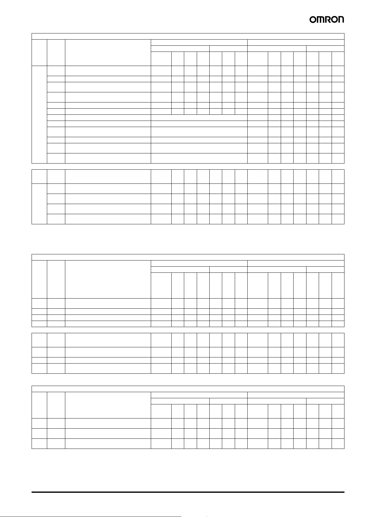
Utilization categories for contactors to IEC 947-4-1 and EN 60947
Verification of electrical endurance Verification of rated making and breaking capacities
Make Break Make Break
I
e
A
I
U
-
-
I
e
cos ϕIc-
U
e
U
r
-
U
I
e
e
cos ϕ
I
e
A
I
U
-
-
I
e
cos ϕ
U
e
All values 1 1 0.95 1 1 0.95 All values 1.5 1.05 0.8 1.5 1.05 0.8
Type of
current
Typical examples of application
I = current made, I
Utilization
Ie = rated operational current
category
U = voltage before make
Ue = rated operational voltage
Ur = recovery volt age
Non-inductive or slightly inductive loads, resistance
AC-1
furnaces
= current broken
c
AC-2 Slip-ring motors: starting, switching off All values 2.5 1 0.65 2.5 1 0.65 All values 4 1.05 0.65 4 1.05 0.65
Squirrel-cage motors: star ting, switching off motors
AC-3
during running
4
AC-4 Squirrel-cage motors: starting, plugging, inching
Ie ≤ 17
Ie > 176611
Ie ≤ 17
Ie > 176611
0.65
0.3511
0.65
0.356611
0.17
0.17
0.65
0.35
0.65
0.35
Ie ≤ 100
Ie > 1001010
Ie ≤ 100
Ie > 1001212
1.05
1.05
1.05
1.05
0.45
0.3588
0.45
0.351010
AC-5A Switching of electric discharge lamp controls - - - - - - - - 3.0 1.05 0.45 3.0 1.05 0.45
2
AC-5B Switching of incandescent lamps - - - - - - - - 1.5
AC
3
AC-6A
Switching of transformers As given by the manufacturer - - - - - - -
1.052)1.521.052)
AC-6B3Switching of capacitor banks As given by the manufacturer - - - - - - -
Slightly inductive loads in household appliances and
AC-7A
similar applications
AC-7B Motor-loads for household applications As given by the manufacturer - 8.0 1.05
Hermetic refrigerant compressor motor control with
DC
AC-8A
manual resetting of overload releases
Hermetic refrigerant compressor motor control with
AC-8B
automatic resetting of overload releases
Non-inductive or slightly inductive loads, resistance
DC-1
furnaces
Shunt motors: starting, plugging, inching, dynamic
DC-3
braking
Series motors: starting, plugging, inching, dynamic
DC-5
braking
5
5
DC-6 Switching of incandescent lamps - - - - - - - -
Note 1: cos ϕ = 0.45 for Ie ≤ 100 A; cos ϕ = 0.35 for Ie > 100 A.
2: The tests are to be carried out with an incandescent light load.
3: The test data are to be derived from the test values for AC-3 or AC-4 according to
Table VIIb, EN 60947-4-1.
As given by the manufacturer - 1.5 1.05 0.8 1.5 1.05 0.8
1
)8.01.051)
As given by the manufacturer - 6.0 1.051)6.01.051)
As given by the manufacturer - 6.0 1.051)6.01.051)
I
U
I
e
A
I
e
L/RmsIc
U
e
U
L/RmsI
r
-
-
I
U
e
e
e
A
I
U
I
e
L/RmsI
U
e
All values 1 1 1 1 1 1 All values 1.5 1.05 1 1.5 1.05 1
All values 2.5 1 2 2.5 1 2 All values 4 1.05 2.5 4 1.05 2.5
All values 2.5 1 7.5 2.5 1 7.5 All values 4 1.05 15 4 1.05 15
1.5
2
)
4: AC-3 category may be used for occasional inching (jogging) or plugging for limited
time periods such as machine set-up; during such limited time periods the number
of such operations should not exceed five per minute or more than ten in a ten
minute period.
5: A hermetic refr igerant compressor motor is a combination consisting of a compres-
sor and a motor, both of which are enclosed in the same housing, with no external
shaft or shaft seals, the motor operating in the refrigerant.
1.05
2
)
Utilization categories for control switches to IEC 947-5-1 and EN 60947
Normal conditions of use Abormal conditions of use
Make Break Make Break
I
U
-
-
I
U
e
e
cos ϕ
I
U
c
r
-
-
I
e
cos ϕ
U
e
I
U
-
-
I
e
cos ϕ
U
e
110.9110.9 - - - - - -
Type of
Utilization
current
category
AC AC-12
Typical examples of application
I = current made, Ic = current broken
= rated operational current
I
e
Ue = rated operational voltage
Ur = recovery volt age
U = voltage before make
t
= time in ms to reach 95 % of the steady-state
0.95
current
P = Ue x Ie = rated power consumption in watts
Control of resistive and solid state loads as in optocoupler input circuits
AC-13 Control of solid state loads with transformer isolation 2 1 0.65 1 1 0.65 10 1.1 0.65 1.1 1.1 0.65
AC-14 Control of small electromagnetic loads (≤ 72 VA) 6 1 0.3 1 1 0.3 6 1.1 0.7 6 1.1 0.7
AC-15 Control of electromagnetic loads (> 72 VA) 10 1 0.3 1 1 0.3 10 1.1 0.3 10 1.1 0.3
I
I
I
1.5
2
I
I
U
c
r
cos ϕ
-
U
e
e
1.05
0.45
1.05
0.35
1.05
0.45
1.05
0.35
U
-
U
1.05
U
U
L/R
r
ms
e
2
)
r
cos ϕ
e
c
e
)
c
e
I
U
-
-
I
U
e
e
111 ms111 ms - - -- - -
DC DC-12
Control of resistive and solid state loads as in optocoupler input circuits
DC-13 Control of electromagnets 1 1 6xP1)1 1 6xP1)1.11.16xP
Control of electromagnetic loads having economy
DC-14
resistors in circuits
Note 1: The value “6 x P” results from an empirical relationship which is found to represent most DC magnetic loads to an upper limit of P = 50 W, viz 6 x P = 300 ms. Loads having power
consumption greater than 50 W are assumed to consist of smaller loads in parallel. Therefore, 300 ms is to be an upper limit, irrespective of the power consumption value.
10 1 15 ms 1 1 15 ms 10 1.1 15 ms 10 1.1 15 ms
I
U
c
t
0.95
r
-
-
t
I
e
0.95
U
e
I
U
-
-
I
U
e
e
I
U
c
t
-
0.95
1
-
I
U
e
)1.1 1.1 6xP1)
r
t
0.95
e
Utilization categories for switches, disconnectors, switch-disconnectors, and fuse combination units to IEC 947-3 and EN 60947
Verification of electrical endurance Verification of switching capacity
Make Break Make Break
I
e
A
I
U
-
-
I
U
e
e
cos ϕ
I
U
c
r
-
-
I
U
e
e
cos ϕ
I
e
A
I
U
-
-
I
U
e
e
cos ϕ
I
U
c
r
-
-
I
e
cos ϕ
U
e
All values1)1)1)1)1)1) All values1)1.051)1)1.051)
All values 1 1 0.95 1 1 0.95 All values 1.5 1.05 0.95 1.5 1.05 0.95
All values 1 1 0.8 1 1 0.8 All values 3 1.05 0.65 3 1.05 0.65
Type of
current
AC
Typical applications
I = current made, Ic = current broken
Utilization
Ie = rated operational current
category
U = voltage before make
Ue = rated operational voltage
Ur = recovery volt age
AC-20
Connecting and disconnecting under no-load condi-
2
A(B)
tions
AC-21
Switching of resistive loads, including moderate
2
A(B)
overloads
AC-22
Switching of mixed resistive and inductive loads, in-
2
A(B)
cluding moderate overloads
Low Voltage Switch Gear Appendix 85
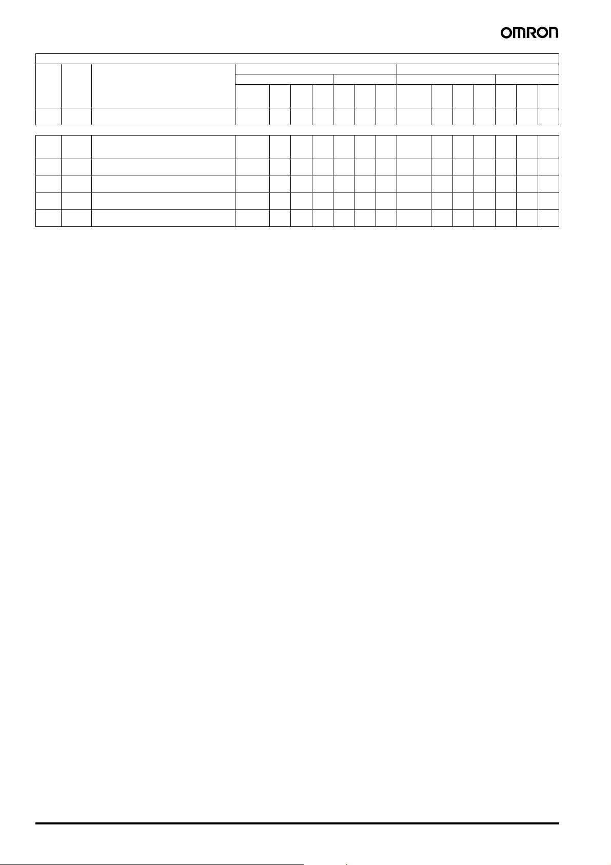
Utilization categories for switches, disconnectors, switch-disconnectors, and fuse combination units to IEC 947-3 and EN 60947
Verification of electrical endurance Verification of switching capacity
Make Bre ak Make Br eak
I
I
e
A
U
-
-
I
e
cos ϕ
U
e
U
I
c
r
-
-
I
e
cos ϕ
U
e
All values 1 1 0.65 1 1 0.65
Type of
current
Typical applications
I = current made, I
Utilization
Ie = rated operational current
category
U = voltage before make
Ue = rated operational voltage
Ur = recovery voltage
AC-23
Switching of motor loads or other highly inductive
2
A(B)
loads
= current broken
c
I
e
A
Ie ≤ 100
Ie > 1001010
I
U
-
U
1.05
1.05
cos ϕ
e
0.45
0.3588
I
e
U
I
c
r
-
U
1.05
1.05
cos ϕ
e
0.45
0.35
I
e
I
e
DC-20
DC
Note 1: If the switching device has a making and/or breaking capacity, the figures for the current and the power factor (time constants) must be stated by the manufacturer.
2: A: frequent operation, B: infrequent operation.
Connecting and disconnecting under no-load condi-
2
A(B)
tions
Switching of resistive loads, including moderate
DC-21
2
overloads
A(B)
DC-22
Switching of mixed resistive and inductive loads, in-
2
A(B)
cluding moderate overloads (e.g. shunt motors)
DC-23
Switching of highly inductive loads (e.g. series mo-
2
A(B)
tors)
A
All values1)1)1)1)1)1)All values1)1.051)1)1.051)
All values111111All values1.51.0511.51.051
All values112112All values41.052.541.052.5
All values 1 1 7.5 1 1 7.5 All values 4 1.05 15 4 1.05 15
Protection against electrical shock, to IEC 536
IEC 536 covers the setting up of electrical apparatus, and its
arrangement in electrical installations with rated voltages up to 1000
VAC and 1500 VDC, with regard to protection against direct contact
I
U
I
e
L/RmsI
U
e
U
c
I
e
L/RmsI
r
U
e
e
A
I
U
I
e
L/RmsI
U
e
Damp heat, constant, to IEC 68 Part 2-3
In this test, the effects of a constant high level of humidity
(93 +2/-3%) and a constant temperature (40 ±2)°C over a prescribed
duration, are observed.
where operating elements such as push-buttons and switches are
located in the vicinity of live parts.
“Finger-proofing” relates only to the operating device, and only in the
normal direction of operation. A clearance of at least 30 mm radius
from the centre point of the device to any live parts, must be ensured.
The IP 20 degree of protection is superior to “finger-proofing” in that
it embodies protection against contact with electrical apparatus in
Damp heat, cyclic, to IEC 68 Part 2 - 30, Test Db
This test is used to assess the suitability of electrical products for
operation and storage at high relative humidity levels, in conjunction
with cyclic temperature fluctuation. A test cycle consists of 12 hours
at 40 ±2°C, with relative humidity of 93 ±3%, and 12 hours at
25 ±3°C, with the relative humidity of at least 95%.
any direction. Devices which are “finger-proof” and of IP 00 degree of
protection can be provided with further protection against contact in
the form of shrouding, if so desired.
Ambient temperature
Ambient temperature is the temperature of the room (e.g. factory bay
or switchgear room), in which the open or enclosed device is
installed, a prerequisite being that this temperature is not significantly
influenced by the heat losses from the device.
U
c
I
e
L/R
r
U
ms
e
86 Low Voltage Switch Gear Appendix

Glossary of standard terms
This Glossary offers brief expIanations of some of the standard
terms used in this catalogue. However, it must not be regarded as a
substitute for the actual text of the standard, especially where the
new terms used in IEC 947 are concerned.
Rated conditional short-circuit current I
(IEC 947-1; 2.5.29/IEV 441-17-20)
The prospective current which a switching device, e.g. a circuitbreaker, protected by a short-circuit protective device such as a
motor-protective circuit-breaker, can carry for the duration of the protective device tripping time.
q
Mininum command time
Minimum duration for a trip-initiating factor (controI puIse, short circuit) to effect the corresponding reaction, e.g. the short-circuit duration necessary to initiate tripping.
Rated breaking capacity
(IEC 947-1; 4.3.5.3)
The r.m.s. value of current which a switching device is capable of
breaking according to its utiIization category. The rated breaking
capacity is stated by reference to the rated operational voltage and
the rated operational current.
The equipment must be capable of breaking any value of current up
to and incIuding its rated breaking capacity stated.
Rated actuating voltage Uc
(rated control circuit voltage)
(IEC 947-1; 4.5.1)
The voltage which is applied to the actuating make contact in a control circuit. Due to the presence in the controI circuit of transformers
or resistors, this voltage may differ from the rated control supply voltage.
Rated service short-circuit breaking capacity I
(IEC 947-2; 4.3.5.2.2)
The prospective short-circuit current which, depending on the rated
operationaI voltage, a circuit-breaker is capable of breaking repeatedly (test cycle: O - CO - CO; previousIy P-2). After interrupting this
current vaIue, the circuit-breaker must be capable, despite its own
thermal level having increased, of continuing to carry and disconnect
in the event of overIoading, the rated uninterrupted current.
Rating or rated power
(IEC 947-1; 4.3.2.3)
The rated operational power which an equipment is capable of
switching at the associated rated operational voItage in accordance
with the utilization category.
For example:
motor contactor utilization category AC-3: 37 kW at 400 V.
Rated operational voltage U
(IEC 947-1; 4.3.1.1)
The voItage to which the characteristics of an equipment are
referred. The rated operational current must not in any case exceed
the rated insulation voltage.
e
Rated operational current Ie
(IEC 947-1; 4.3.2.3)
The current which an equipment is capabIe of carrying taking into
account the rated operational current, duration of operation, utilization category and ambient temperature.
Reference is therefore made aIongside each such term to the reIevant section of the standard, e.g. IEC 947-1 in addition, IEV numbers
are given to enable you to find foreign language equivalents in the
International EIectrotechnicaI Vocabulary
(IEG 50), if required.
Rated uninterrupted current I
(IEC 947-1; 4.3.2.4)
The vaIue of current which an equipment can carry in uninterrupted
duty (i.e. for weeks, months or years).
u
Rated making capacity
(IEC 947-1; 4.3.5.2)
The vaIue of current which an equipment is capabIe of switching On
in accordance with the utilization category and at the rated operational voltage.
Rated frequency
(IEC 847-1; 4,3.3)
The frequency for which an equipment is designed and to which the
other characteristic vaIues are referred.
Rated ultimate short-circuit breaking
capacity I
(IEC 947-2; 4.3.5.2.1)
The maximum prospective fault current which a circuit-breaker is
capable of interrupting
(test cycIe: O - CO; previously P-1)
Rated insulation voltage U
(IEG 947-1; 4.3.1 .2)
The voltage to which insulation tests and creepage distances of an
equipment are referred. The maximum operationaI voltage must not
in any case exceed the rated insulation voltage.
cs
Rated short-circuit breaking capacity Icn
(IEC 947-1; 4.3.6.3)
The maximum value of current which an equipment is capable of
switching Off at rated operational voItage and rated frequency, and
without sustaining damage. It is expressed as r.m.s. value.
cu
i
Motor rating
(IEC 947-1; 4.3.2.3)
Power output of a motor at the associated operational voltage.
Rated control supply voltage Us
(IEC 947-1; 4.5.1)
The voltage applied to the input terminals of the control circuit of an
equipment. Due to the presence of transformers or resistors in the
control circuit, this may differ from the rated actuating (control circuit)
voltage.
Rated impulse withstand voltage U
(IEC 947-1; 4.3.1 .3)
Measures the stability of the internal clearances of an equipment
against overvoltage peaks. The utilization of suitable switchgear can
ensure that overvoltages are prevented from transferring from the
mains to deenergized system sections within it.
Rated current I
(of a circuit-breaker)
(IEC 947-2; 4.3.2.3)
For circuit-breakers, this current value is equal to the uninterrupted
current and the conventional free air thermaI current.
n
imp
Low Voltage Switch Gear Appendix 87
 Loading...