

Page 1

EM2100
Installation Guide
1
I634-E-04
Page 2

Copyright Notice
The information contained herein is the property of OMRON and shall not be reproduced in whole or in
part without prior written approval of OMRON The information herein is subject to change without
notice and should not be construed as a commitment by OMRON The documentation is periodically
reviewed and revised.
OMRON assumes no responsibility for any errors or omissions in the documentation. Critical evaluation
of the documentation by the user is welcomed. Your comments assist us in preparation of future documentation. Please submit your comments to: techpubs@omron.com.
Copyright 2020 by OMRON Corporation. All rights reserved.
Any trademarks from other companies used in this publication
are the property of those respective companies.
Created in the United States of America
Page 3

Table of Contents
Chapter 1: Introduction
1.1 Description of the EM2100
1.2 Items Supplied with the EM2100
Additional Equipment used with the EM2100
1.3 How to Get Help
Related Manuals
Chapter 2: Safety
2.1 Alert Levels
Alert Icons
Special Information
2.2 Safety Precautions for the EM2100
General Hazards
2.3 Disposal
Chapter 3: HardwareOverview
3.1 Front Panel Connectors and Features
3.2 Rear Panel Connectors and Features
3.3 Display Panel Information
Autosync Status
7
7
7
8
8
8
11
11
12
12
13
13
14
15
15
16
17
18
Chapter 4: Hardware Installation
4.1 Prepare Your Site for the EM2100
Site Rack Requirements
Site Electrical Power Requirements
Electrical Wiring
Site Networking Requirements
Local Area Network (LAN) Requirements
Wireless Network Requirements
4.2 Unpack the Shipment
Before You Unpack the EM2100
Unpack the EM2100 Shipping Carton
4.3 Sliding Rail Kit for Rack Mounting
Components in the Sliding Rail Kit
Items Required to Install the Sliding Rail Kit
Determine the Mounting Method for the Sliding Rail Kit
Determine the Sliding Rail Kit Installation Location on the Rack
20569-000 Rev. D EM2100 Installation Guide 3
19
19
19
20
20
21
21
21
22
22
22
24
25
26
26
26
Page 4

Table of Contents
Remove the Sliding Rail from the Sliding Track
Attach the Sliding Rails to the Appliance Chassis
Attach the Outer L-shaped Brackets to the Sliding Track
Attach the Sliding Tracks to the Rack Posts
Insert the Appliance Into the Sliding Track
Appliance Removal
4.4 Connecting Power to the EM2100
Chapter 5: Operation
5.1 Turn EM2100 Power ON and OFF
Powering ON
Powering OFF - Soft Shutdown
Powering OFF - HardShutdown
Considerations for Powering ON After a Shutdown
5.2 Mixed Laser Support
5.3 Legacy Fleets
Chapter 6: Connecting to theEM2100
6.1 Set the IP Address on the Client PC's Network Adapter
6.2 Access SetNetGo on the EM2100
Access SetNetGo with a WebBrowser
Access SetNetGo with MobilePlanner
27
27
28
29
31
32
33
35
35
35
35
36
36
37
37
39
39
39
40
41
Chapter 7: Troubleshooting
7.1 Troubleshooting Methods
7.2 Including a debugInfo File with Your Help Request
Chapter 8: Transport and Storage of the EM2100
Chapter 9: Technical Specifications
9.1 Processing Specifications
9.2 Environmental Specifications
9.3 Power Requirements
9.4 Physical Characteristics
43
43
44
45
47
47
47
47
48
4 EM2100 Installation Guide 20569-000 Rev. D
Page 5

Table of Contents
Revision History
Revision
code
01 June, 2019 Original release
02 October, 2019 Changes for new mounting rail sizes.
03 January, 2020 Changes for the release of the Fleet Simulator.
04 March, 2020 Update for SetNetGo changes.
Date Revised Content
20569-000 Rev. D EM2100 Installation Guide 5
Page 6

Page 7

This chapter provides an introduction to the EM2100 appliance. It includes the following topics.
1.1 Description of the EM2100 7
1.2 Items Supplied with the EM2100 7
1.3 How to Get Help 8
1.1 Description of the EM2100
The EM2100 is a computing appliance with a processor capable of running the Fleet Operations Workspace Core suite.
The EM2100 appliance can be configured for the following operating modes.
l
Standalone Fleet Manager
This has the ability to connect to, communicate with, and control the AMR fleet.
l
Paired:Primary Fleet Manager
This is similar to the Standalone Fleet Manager, but also communicates with a Secondary Fleet Manager, which serves as a backup if the Primary ever fails.
Chapter 1: Introduction
l
Paired:Secondary Fleet Manager
This functions as a backup appliance for the Primary.
l
Fleet Simulator
This can simulate up to ten AMRs divided between up to three fleets.
The installation of theEM2100 appliance is the same regardless of which operating mode the
appliance will be used for.
Additional Information: Details for the use and configuration of the functions
above can be found in the Fleet Operations Workspace CoreUser's Guide and the
Fleet Simulator User's Guide.
NOTE: The EM2100 appliance can support legacy AMR fleet management. To
configure the EM2100 for use with legacy fleets, refer to the Fleet
OperationsWorkspace Migration Guide.
1.2 Items Supplied with the EM2100
The EM2100 appliance is supplied with the following items.
l
Rack-mount rail kit for a four-post data center rack
l
Power cable set, including cables for use in various locales world-wide
20569-000 Rev. D EM2100 Installation Guide 7
Page 8

1.3 How to Get Help
Additional Equipment used with the EM2100
The following equipment is used during the normal operation of the EM2100.
l
An uninterruptable power supply (UPS) is recommended (refer to Power Requirements
on page 47 for more information). If your manufacturing execution system or enterprise
resource planning system is maintained by a UPS, including this for the EM2100 will
help ensure that the integrity of these systems is maintained through any brief power
outages.
l
Network infrastructure necessary for communication and optionally for redundant network communication (if you use a Paired Secondary Fleet Manager).
l
OMRON Autonomous Mobile Robots (AMRs).
l
Compatible Windows PC clients to run MobilePlanner for remote access to the appliance and AMRs.
1.3 How to Get Help
To obtain support assistance with your software or hardware, visit our website at:
http://www.ia.omron.com.
Related Manuals
This manual describes the installation and basic operation of the EM2100 appliance. The following manuals provide more information about safety, use, and advanced configurations for
the EM2100 and related products.
Table 1-1. Related Manuals
Manual Title Description
Mobile Robot LDSafety Guide Describes AMR safety aspects.
Fleet Operations Workspace
CoreUser's Guide
Fleet Simulator User's Guide Describes use of the EM2100 in the Fleet Simulator operating
Fleet Operations Workspace
Core Migration Guide
Integration Toolkit User's
Guide
Advanced Robotics Command Language Reference
Guide
Describes use of the EM2100 and the software that runs on it
for managing a fleet of AMRs.
mode.
Describes how to upgrade a system between Legacy and FLOW
Core solutions which includes software upgrade processes and
tools as well as guidance on any necessary hardware changes.
Describes a flexible array of interfaces to control and monitor
AMRs with various client applications.
Describes the Advanced Robotics Command Language (ARCL),
which is a simple, text-based server from which you can control our AMRs.
LD Platform OEMUser's
Guide
LD Platform Cart
TransporterUser's Guide
Describes the operation and maintenance of the LD-60 and
LD-90 AMRs.
Describes the operation and maintenance of the Cart Transporter AMR.
8 EM2100 Installation Guide 20569-000 Rev. D
Page 9

Manual Title Description
Chapter 1: Introduction
LD-250 Platform User's
Guide
LDPlatform Peripherals
Guide
Describes the operation and maintenance of the LD-250 AMR.
Describes various peripherals available for use with LD-series
AMRs.
20569-000 Rev. D EM2100 Installation Guide 9
Page 10

Page 11

This chapter provides information about product safety. It includes the following topics.
!
!
!
!
!
!
2.1 Alert Levels 11
2.2 Safety Precautions for the EM2100 13
2.3 Disposal 14
2.1 Alert Levels
There are three levels of alert notation used in our manuals. In descending order of importance, they are:
DANGER: Identifies an imminently hazardous situation which, if not
avoided, is likely to result in serious injury, and might result in fatality or
severe property damage.
DANGER: Identifie une situation dangereuse imminente qui, si elle n’est pas
évitée, est susceptible d’avoir comme résultat une blessure grave et pourrait
provoquer le décès ou des dommages matériels importants.
Chapter 2: Safety
WARNING: Identifies a potentially hazardous situation which, if not avoided,
will result in minor or moderate injury, and might result in serious injury, fatality, or significant property damage.
AVERTISSMANT: Identifie une situation dangereuse potentielle qui, si elle
n’est pas évitée, aura comme résultat une blessure mineure ou modérée et pourrait provoquer une blessure grave, le décès, ou des dommages matériels significatifs.
CAUTION: Identifies a potentially hazardous situation which, if not avoided,
might result in minor injury, moderate injury, or property damage.
ATTENTION: Identifie une situation dangereuse potentielle qui, si elle n’est
pas évitée, pourrait avoir comme résultat une blessure mineure ou des dommages matériels.
20569-000 Rev. D EM2100 Installation Guide 11
Page 12
2.1 Alert Levels
!
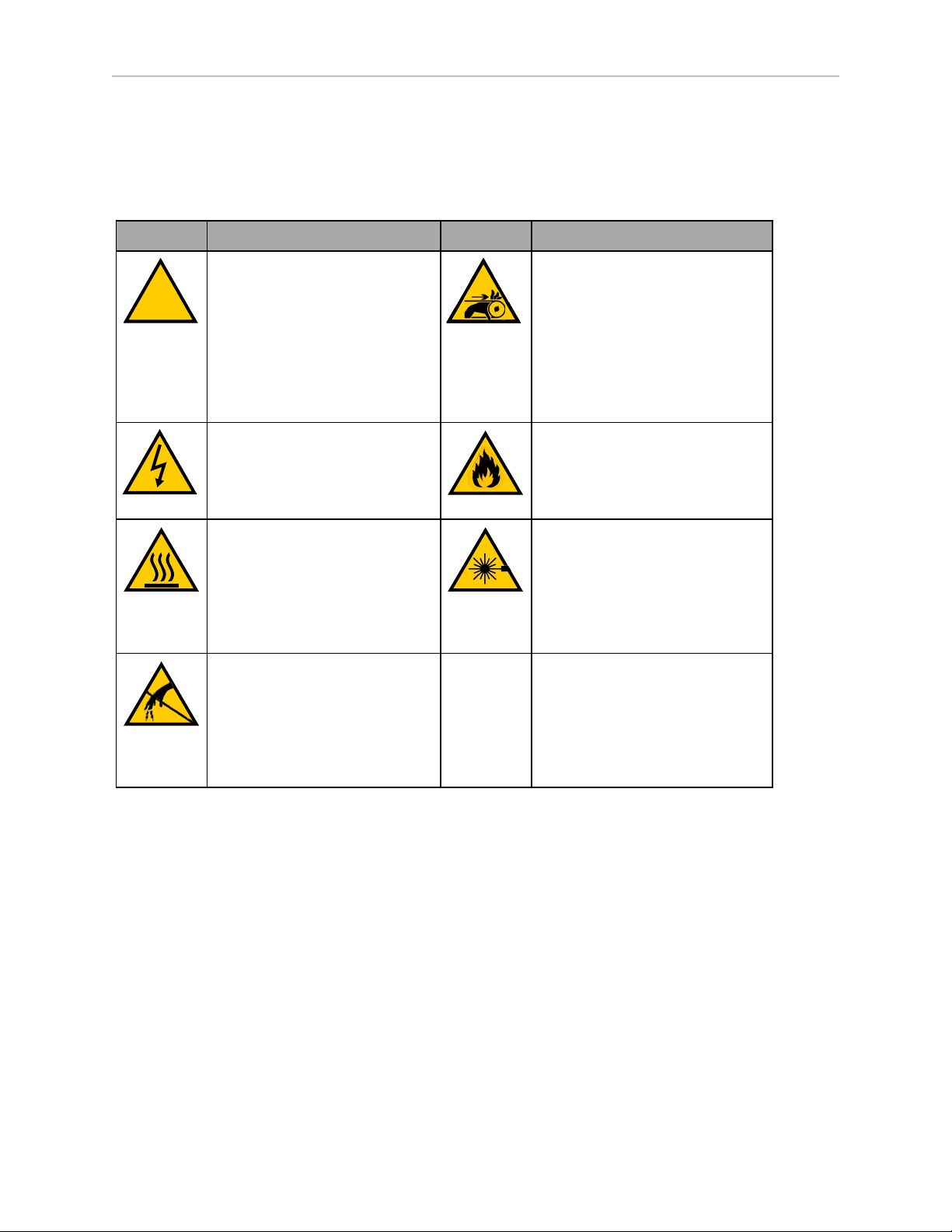
Alert Icons
The icon that starts each alert can be used to indicate the type of hazard. These will be used
with the appropriate signal word - Danger, Warning, or Caution - to indicate the severity of the
hazard. The text following the signal word will specify what the risk is, and how to avoid it.
Icon Meaning Icon Meaning
This is a generic alert icon. Any
specifics on the risk will be in the
text following the signal word.
Ceci est un symbole générique
d’alerte. Toute spécificité concernant le risque sera décrite
dans le texte après le mot de signalement.
This identifies a hazardous electrical situation.
Ceci identifie une situation
dangereuse électrique.
This identifies a hazardous burnrelated situation.
Ceci identifie une situation
dangereuse de brûlure.
This identifies a hazardous ESD
situation.
This identifies a hazardous entanglement situation.
Ceci identifie une situation
dangereuse d’enchevêtrement.
This identifies a fire risk.
Ceci identifie un risque
d’incendie.
This identifies a laser emitter eye
damage situation.
Ceci identifie une situation
dangereuse liée aux lésions oculaires provoquées par un
émetteur laser.
Ceci identifie une situation
dangereuse ESD (décharges
électrostatiques).
Special Information
There are several types of notation used to call out special information.
IMPORTANT: Information to ensure safe use of the product.
NOTE: Information for more effective use of the product.
Additional Information: Offers helpful tips, recommendations, and best prac-
tices.
Version Information: Information on differences in specifications for different
versions of hardware or software.
12 EM2100 Installation Guide 20569-000 Rev. D
Page 13
2.2 Safety Precautions for the EM2100
!
!
!
!
Read the installation and operation instructions before using the appliance.
If you use the supplied rail kit to install the appliance into a 4-post data center rack, make sure
you read and follow the safety instructions provided with the rack.
General Hazards
CAUTION: PERSONAL INJURYRISK.Do not begin any tasks in this
manual that result in activating an AMR (autonomous mobile robot) until you
have read the important safety information in the Mobile Robot LDSafety
Guide and in the AMRs' user manuals.
ATTENTION: RISQUE DE BLESSURES PERSONNELLES. Ne pas initialiser
une tâche dans ce manuel qui ait comme résultat l’activation d’un AMR (robot
mobile autonome) avant de lire les renseignements importants de sécurité dans
le Guide de Sécurité LD pour Robots Mobiles et dans les manuels d’utilisation
AMR.
Chapter 2: Safety
CAUTION: PERSONAL INJURYRISK. Observe all safety precautions when
installing the appliance in a computer rack. Two persons might be required to
safely lift and install the appliance into a tall rack.
ATTENTION: RISQUE DE BLESSURES PERSONNELLES. Respecter toutes
les précautions de sécurité lors de l’installation de l’appareil dans un support
d’ordinateur. Deux personnes pourraient être nécessaires pour élever et
installer l’appareil dans un support haut en toute sécurité.
WARNING: ELECTROCUTION RISK. This appliance uses AC power and
presents an electrical shock hazard if used improperly. Do not open the enclosure. No user-serviceable parts are included inside.
AVERTISSMANT: RISQUE D'ÉLECTROCUTION. Cet appareil utilise du
courant CA et présente un risque de choc électrique s’il n’est pas utilisé de manière adéquate. Ne pas ouvrir le boîtier. Aucune pièce interne réparable par
l’utilisateur.
WARNING: ELECTROCUTION RISK. Failing to properly ground equipment
that uses hazardous voltages could lead to injury or death of a person touching
the equipment during an electrical fault.
20569-000 Rev. D EM2100 Installation Guide 13
Page 14
2.3 Disposal
2.3 Disposal
AVERTISSMANT: RISQUE D'ÉLECTROCUTION. Ne pas mettre correctement à la terre un équipement utilisant des tensions dangereuses pourrait
avoir comme résultat la blessure grave, même le décès d’une personne qui le
toucherait pendant une panne électrique.
WARNING: ELECTROCUTION RISK. AC power installation must be performed by a skilled and instructed person. Ensure compliance with all local
and national safety and electrical codes for the installation and operation of the
equipment.
AVERTISSMANT: L'installation CA sera effectuée par une personne qualifiée
et instruite. Assurer la conformité avec tous les codes de sécurité et électriques
locaux et nationaux lors de l'installation et du fonctionnement de l'équipement.
Dispose of in accordance with applicable regulations.
Customers can contribute to resource conservation and protecting the environment by the
proper disposal of WEEE (Waste Electronics and Electrical Equipment). All electrical and electronic products should be disposed of separately from the municipal waste system via designated collection facilities. For information about disposal of your old equipment, contact your
local OMRONsupport.
14 EM2100 Installation Guide 20569-000 Rev. D
Page 15
Chapter 3: HardwareOverview
1 1
10
2
3
4
5
6
7
8
9
This section describes the EM2100 appliance hardware connections, indicators, and other features. It includes the following topics.
3.1 Front Panel Connectors and Features 15
3.2 Rear Panel Connectors and Features 16
3.3 Display Panel Information 17
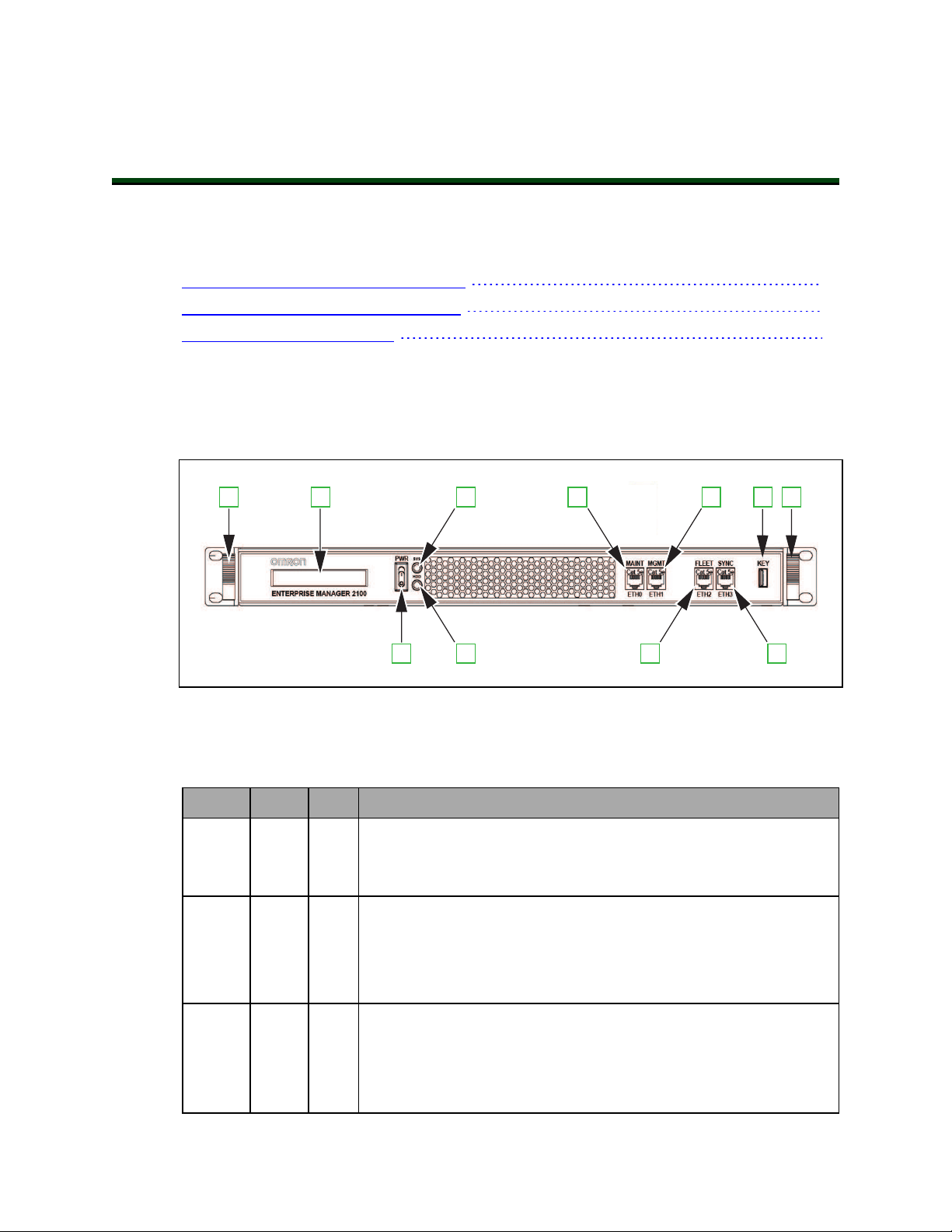
3.1 Front Panel Connectors and Features
This section describes the connectors, indicators, and physical characteristics of the EM2100
appliance front panel.
Figure 3-1. EM2100 Appliance Front Panel Features and Connectors.
Table 3-1. EM2100 Front Panel Description
Callout Label Port Description
1 n/a n/a Chassis handles
Used during installation, removal, or service of the EM2100 appliance to move the chassis on the slider rails.
2 n/a n/a Display panel
This 40-Character (2x20) LCD display provides status, warning, and
error information.
See Display Panel Information on page 17.
3 PWR n/a Power switch
This momentary rocker-type switch controls the power ON and OFF
functions of theEM2100.
See Turn EM2100 Power ON and OFF on page 35 for more
20569-000 Rev. D EM2100 Installation Guide 15
Page 16

3.2 Rear Panel Connectors and Features
Callout Label Port Description
information.
4 SYS n/a System status indicator LED
Indicates the power state of the EM2100 appliance (lit when the
appliance is powered ON).
5 HDD n/a Internal storage activity indicator LED
Lit while the internal hard drive disk is busy (read / write activity).
6 MAINT ETH0 Maintenance Ethernet network port
The Maintenance port is always enabled and is not password protected. Use this port for initial setup, troubleshooting, and as an
alternate method of access.
This port has a static IP address of 1.2.3.4.
7 MGMT ETH1 Management Ethernet network port
The SetNetGo access Ethernet port (AMRs cannot access this Ethernet port).
8 FLEET ETH2 Fleet Ethernet network port
The port for AMR and MobilePlanner operational network connections.
9 SYNC ETH3 Synchronization Ethernet network port
Reserved for future use.
10 KEY n/a Front USBport
Service use or Legacy fleet support dongle.
Additional Information: Contact your system administrator for assistance configuring the EM2100 appliance for your network. Refer to Site Networking
Requirements on page 21 for more information.
3.2 Rear Panel Connectors and Features
This section describes the connectors, indicators, and physical characteristics of the EM2100
appliance rear panel.
Figure 3-2. EM2100 Rear Panel Connectors and Features.
16 EM2100 Installation Guide 20569-000 Rev. D
Page 17

Chapter 3: HardwareOverview
The EM2100 rear panel connectors and features are described in the following table.
Table 3-2. Description of EM2100 Rear Panel Connectors and Features
Callout Description
1 Four USB ports
Service use or Legacy fleet support dongle.
2 SVGA Video DB15 port
Service use only.
3 Four auto-speed motherboard cooling fans
Fan speed (and noise volume) varies depending on the CPU load and the ambient
temperature.
4 Power supply cooling fan
5 AC power input connector (IEC 60320 C14)
6 Main power input switch
Keep this set to ON (I) during normal operation and use the front power switch to
control power. Refer to Turn EM2100 Power ON and OFF on page 35 for more information.
3.3 Display Panel Information
The EM2100 includes an LCD display panel that provides status and other information
described in the following table.
Table 3-3. EM2100 Status Display Messages
Message Description
OMRON ROBOTICS AND SAFETY
TECHNOLOGIES
EM2100 STARTING Boot message after power ON.
MODE: <mode> Configuration mode of the appliance.
Standard splash message during power ON.
FLEET MANAGER STANDALONE: Configured as a
Standalone Fleet Manager.
FLEET MANAGER PAIRED: Configured as a Primary Fleet
Manager or a Secondary Fleet Manager.
SIMULATOR: Configured as a Fleet Simulator.
ETH0: <state> ETH1:<state>
ETH2:<state> ETH3:<state>
Link status of each port.
UP: Ethernet link established.
DOWN:Ethernet link not established.
20569-000 Rev. D EM2100 Installation Guide 17
Page 18

3.3 Display Panel Information
Message Description
ETH1:<###.###.###.###>
ETH2: <###.###.###.###>
ASYNC: <mode>
STATUS: <status>
NOTE:This display will only
appear when the appliance MODE
is PAIRED, either as Primary Fleet
Manager or
Secondary Fleet Manager.
UP:<time> Time elapsed since the last reboot.
IPv4 address for the Management Ethernet port and the
Fleet Ethernet port.
Autosync mode and status when an EM2100 appliance is
paired, operating as either a Primary Fleet Manager or
Secondary Fleet Manager.
The mode will be displayed as PRIMARYor SECONDARY.
The status will be displayed as STARTUP, ACTIVE, or
FAILED. See Autosync Status on page 18 for more information.
Autosync Status
Autosync Status only applies to installations with a Primary Fleet Manager and a Secondary
Fleet Manager. The autosync status messages are described below.
l
STARTUP—Autosync is configured, but the two appliances have not yet communicated successfully.
l
ACTIVE—The Primary Fleet Manager and Secondary Fleet Manager appliances are
communicating.
l
FAILED—The Primary Fleet Manager and Secondary Fleet Manager appliances were
previously communicating, but the connection is lost. The Primary Fleet Manager automatically attempts to re-establish communication with the Secondary Fleet Manager in
this state.
18 EM2100 Installation Guide 20569-000 Rev. D
Page 19

Chapter 4: Hardware Installation
!
!
This chapter provides information about unpacking, mounting, and applying power to the
EM2100 appliance hardware. It includes the following topics.
4.1 Prepare Your Site for the EM2100 19
4.2 Unpack the Shipment 22
4.3 Sliding Rail Kit for Rack Mounting 24
4.4 Connecting Power to the EM2100 33
4.1 Prepare Your Site for the EM2100
Use this information to prepare a site for an EM2100 installation.
WARNING: HAZARDOUS ENVIRONMENTS. OMRON does not intend
that you use the EM2100 appliance in hazardous environments (explosive gas,
water, dust, oil mist). The appliance has an IP rating of IP20 (NEMA Type 1).
AVERTISSMANT: OMRON n’a pas conçu l’appareil EM2100 pour être utilisé dans des environnements à risque (gaz explosif, eau, poussière, brouillard
huileux). L’appareil a un indice IP20 (NEMA Type 1).
For other technical specifications and requirements, see: Technical Specifications on page 47.
Site Rack Requirements
Each EM2100 requires 1U (44.50 mm, 1.75 inches) of space in a standard 19-inch (48.3 cm) 4post data center rack, installed as follows:
l
The appliance requires a minimum of four support points at the sides, or a rack shelf
that provides full support for the chassis enclosure.
l
You must secure the appliance to the rack with screws. This prevents anyone from
attempting to slide the appliance out of the rack.
IMPORTANT: Do not install this appliance in a 2-post rack, or mount it by the
chassis bezel brackets (ears) alone. If rack mounting is not possible, mount the
appliance with a support shelf or support brackets that can bear the entire
weight of the unit.
If you are installing a Secondary Fleet Manager, consider installing it in a rack that is remote
from the Primary Fleet Manager to improve disaster tolerance.
20569-000 Rev. D EM2100 Installation Guide 19
Page 20

4.1 Prepare Your Site for the EM2100
!
!
!
!
DANGER: PERSONAL INJURY RISK. When installing equipment in a rack,
read and follow all safety instructions in the rack documentation. Follow the
instructions for stabilizing the rack before you begin the installation.
DANGER: RISQUE DE BLESSURES PERSONNELLES. Lors de l'installation
de l'équipement dans un support, lire et suivre toutes les instructions de sécurité de la documentation du support. Suivre les instructions pour stabiliser le
support avant de commencer l’installation.
WARNING: PERSONAL INJURY RISK. Installation might require two
people to safely lift and install this equipment in a tall rack.
AVERTISSMANT: RISQUE DE BLESSURES PERSONNELLES. Deux personnes pourraient être nécessaires pour élever et installer l’appareil dans un
support haut en toute sécurité.
Site Electrical Power Requirements
The appliance has specific electrical power requirements that should be considered when preparing your site for installation. Refer to Technical Specifications on page 47 and the electrical
safety information specified in Safety on page 11.
If using a paired appliance configuration, we recommend that you use an uninterruptible
power supply (UPS) for the Primary Fleet Manager and a separate UPS for the Secondary Fleet
Manager. If you do not use a UPS and you install two appliances in the same rack, connect
each appliance to different power distribution units on separate circuits for power redundancy.
Electrical Wiring
Your EM2100 shipment includes approved power cables for several global locales. If it is
necessary to manufacture custom power cables to comply with site-specific or equipment-specific wiring, make sure that the cable rating and capacities comply with the specifications
found in Power Requirements on page 47.
Chassis grounding occurs at the screws mounting the appliance to the rack through the supplied rail kit. If wired grounding (or bonding) is a requirement for your site, use an appropriate
custom cable according to local electrical regulations.
Before attempting electrical wiring:
l
Read and understand the safety recommendations in Chapter 2: Safety.
l
Ensure electrical installers are suitably trained and qualified to perform the work.
l
Complete any necessary electrical work in accordance with local regulations.
l
Ensure that you ground and bond the rack according to local electrical specifications.
20 EM2100 Installation Guide 20569-000 Rev. D
Page 21

Chapter 4: Hardware Installation
DANGER: ELECTROCUTION RISK. Follow all local safety regulations that
determine who can install such equipment, and how to install it. Follow all
local safety and mechanical regulations governing the installation of rackmounted computer equipment, including power supplies, connectors, grounding, and wiring.
DANGER: RISQUE D'ÉLECTROCUTION. Respecter toutes les réglementations de sécurité locales qui établissent qui peut installer un tel équipement et la méthode d’installation. Respecter toutes les réglementations locales
en matière de sécurité et de mécanique régissant l'installation des équipements
informatiques montés sur support, notamment l'alimentation, les connecteurs,
la mise à la terre et le câblage.
Site Networking Requirements
The following sections only apply to an EM2100 that is in either Standalone Fleet Manager or
Primary Fleet Manager operating mode. These networking requirements do not apply to an
EM2100 in either Secondary Fleet Manager or Fleet Simulator operating modes.
Local Area Network (LAN) Requirements
An EM2100 running the Fleet Operations Workspace Core software is typically connected to
the following items during normal operation.
l
AMR wireless network
l
Operator Terminal(s)
l
Factory equipment management systems (WMS or MES)
The EM2100 appliance requires two static IP address assignments for the Management and
Fleet networks (MGMT ETH1 and FLEET ETH2 ports). Each AMR in the system will also
require a static IP address assignment.
A different subnet may be required for the Management and Fleet networks depending on the
local infrastructure. Although it is not required, using a different subnet for each network will
enable you to isolate fleet data traffic from management traffic for enhanced security.
Wireless Network Requirements
Network resource availability can affect EM2100 performance and the number of AMRs supported.
The Fleet Operations Workspace CoreUser's Guide and the AMR user's guides provide additional
information about requirements for wireless networks and network access points. Be aware of
the specific requirements for wireless network coverage and bandwidth.
20569-000 Rev. D EM2100 Installation Guide 21
Page 22

4.2 Unpack the Shipment
4.2 Unpack the Shipment
Unpack the shipment on a clean, level, electrostatic discharge-safe (ESD-safe) surface that is
near the installation location. Make sure that the workspace is large enough to accommodate
both the shipping carton and the unpacked appliance.
CAUTION: ESD DAMAGERISK. Protect the appliance from damage caused
by electrostatic discharge (ESD). Wear a grounded wrist-strap or shoe strap
before you remove the antistatic cover.
ATTENTION: RISQUE DE DÉCHARGE ÉLECTROSTATIQUE. Protéger
l’appareil contre les dommages provoqués par les décharges électrostatiques
(ESD). Portez un bracelet antistatique à la poignée ou à la cheville avant de
retirer le couvercle antistatique.
Before You Unpack the EM2100
Before you unpack the appliance:
l
Orient the carton only as indicated by its labeling (This Way Up).
l
Carefully inspect the packaging for evidence of damage during transit. If you find packaging damage, request that the carrier’s agent be present when you open the packaging.
As the appliance is unpacked:
1.
Compare the actual items received (not just the packing slip) with your equipment purchase order.
2. Verify that all items are present and that the shipment is correct. Refer to Items Supplied with the EM2100 on page 7.
3.
Inspect each component for external damage as you unpack it. Contact your local
OMRONsupport immediately if you see any damage.
Unpack the EM2100 Shipping Carton
1.
Place the shipping carton on a stable, flat surface.
2.
Use only a safety box cutter to cut the packing tape. Do not use any other type of knife
because you might damage the contents. Open the carton as shown in Figure 4-1.
22 EM2100 Installation Guide 20569-000 Rev. D
Page 23

Chapter 4: Hardware Installation
Figure 4-1. EM2100 Shipping Carton Content
3.
Verify that the shipping carton contains the items listed in Table 4-1.
Table 4-1. Description of the Shipping Carton Content
Callout Description
1 Shipping carton
2 Rack-mount rail kit
3 Accessories and documentation bag
4 Power cables
5 EM2100 appliance
6 Shock-absorbing corners
7 Anti-static bag
4.
Remove the accessories bag [3], the rail kit box [2] and the power cables [4].
5.
Carefully lift out the appliance [5] and remove the four shock absorbing [6] corners and
then remove the antistatic bag [7].
6. Put the packaging items back in the shipping carton and retain them for future use. We
recommend that you ship or move the appliance only in its original packaging.
20569-000 Rev. D EM2100 Installation Guide 23
Page 24

4.3 Sliding Rail Kit for Rack Mounting
!
!
!
!
!
4.3 Sliding Rail Kit for Rack Mounting
Your EM2100 shipment includes a universal sliding rail kit compatible with generic data center 4-post rack systems. The rail kit can be attached to a variety of rack post profiles with
square or round fastening holes.
You cannot install the EM2100 in a 2-post, Telco-style rack. The bezel brackets (ears) are not
designed to support the chassis weight. However, you may be able to use other 2-post racks for
your appliance with the following considerations.
l
The chassis must be supported with a method that prevents flexing. This can be accomplished with a minimum of 4 mounting points at the corners of the chassis.
l
Use a rack shelf that fully supports the appliance.
Refer to Physical Characteristics on page 48 to verify proper clearance and fit with your rack
system.
WARNING: PERSONALINJURYRISK. When operating the sliding rail during assembly or normal use, take care that you do not insert your fingers
between moving parts.
AVERTISSMANT: RISQUE DE BLESSURES PERSONNELLE. Lors de
l'utilisation du rail télescopique pendant le montage ou l'utilisation normale,
veiller à ne pas insérer les doigts entre les pièces mobiles.
WARNING: HEAVY COMPONENT. Although one person can lift the appliance, you might require a minimum two person lift if you install the appliance
into the upper locations of a tall (183 cm, 72 inch) rack. Take particular care if
you use step ladders or step stools.
AVERTISSMANT: COMPOSANT LOURD. Bien qu’une seule personne
puisse soulever l’appareil, un nombre minimum de deux personnes pourrait
être nécessaire pour installer l’appareil dans un support haut (183 cm, 72
pouces). Prendre un soin particulier lors de l’utilisation d’une échelle ou d’un
tabouret-escabeau.
DANGER: TIPPING RISK. If a computer equipment rack is not ganged to
other racks, bolted to the floor, or fitted with an extending stabilizer foot, it
might tip when equipment is fully extended from the rack. Do not install equipment in a rack unless you are sure that it is stable and safe.
24 EM2100 Installation Guide 20569-000 Rev. D
Page 25

Chapter 4: Hardware Installation
!
1
2
5
4
3
DANGER: RISQUE D'INSTABILITÉ. Si un support d’équipement informatique n’est pas connecté à d’autres supports, boulonné au sol ou équipé d’un
pied stabilisateur extensible, il risque de basculer lorsque l’équipement est complètement sorti du support. Ne pas installer d'équipement dans un support à
moins d’être certain qu'il est stable et sûr.
Components in the Sliding Rail Kit
The sliding rail kit provided with your EM2100 appliance includes the following items.
Figure 4-2. Sliding Rail Components (Right Assembly Shown).
l
Two sliding tracks [1] that attach to the rack posts with brackets.
l
Two sliding rails [2] that attach to the appliance chassis.
l
Two front outer L-brackets [3] that attach to the front rack posts.
l
Two rear outer L-brackets [4] (approximately 6 inch)that attach to the rear rack posts.
l
Two long rear outer L-brackets (11 inch) that attach to the rear rack posts.
Use the longer rear L-brackets (not shown) for rack depths over 24 inches.
l
Four inner L-brackets used to secure the sliding tracks to the rack posts [5].
l
A variety of fasteners and hardware (described in Table 4-2. below).
20569-000 Rev. D EM2100 Installation Guide 25
Page 26

4.3 Sliding Rail Kit for Rack Mounting
Table 4-2. Rail Kit Fasteners
Item Quantity
M5x15 screw 2
M5x8 screw 10
M4x6 screw 14
M4x5 screw 12
M4x4 screw 10
M4 hex nut 8
M4 washer 10
NOTE: To prevent fasteners from loosening because of vibration, use threadlocking liquid (except where electrical grounding is a requirement).
Additional Information: Extra fasteners are provided for various rack mounting
configurations.
Items Required to Install the Sliding Rail Kit
The following items are required to install the Sliding Rail Kit:
l
Phillips torque screwdriver with #2 bit.
l
Something to mark the rack post mounting positions, such as a permanent marker.
l
A clamping device or other means to temporarily hold the rail in position while fastening.
l
Thread-locking liquid (Loctite®Blue 242 adhesive or equivalent).
Determine the Mounting Method for the Sliding Rail Kit
The sliding rail kit adapts to different rack post profiles in several ways. Use the supplied Lbrackets to determine which fastener holes you will use to attach the sliding rail kit to the rack
posts.
Adjust the position of the L-brackets to contact the inner or outer surfaces of the rack post to
confirm hole alignment.
NOTE: The front and rear outer L-brackets might attach directly to the post
without requiring the inner L-brackets for some rack profile types.
Determine the Sliding Rail Kit Installation Location on the Rack
Determine the installation location as follows.
1.
Determine the rack post height (U location) where you want to install the appliance.
2.
Mark the installation location on all four rack posts.
26 EM2100 Installation Guide 20569-000 Rev. D
Page 27

Chapter 4: Hardware Installation
Remove the Sliding Rail from the Sliding Track
Remove the sliding rail [1] from the sliding track [2] as follows.
Figure 4-3. Remove the Sliding Rail from the Sliding Track (Right Assembly Shown).
1.
Pull the end of the sliding rail [1] until it is fully extended from the sliding track [2],
engaging the locking button [3].
2.
Press the locking button [3] and continue to pull the sliding rail [1], removing it completely from the track.
3.
Repeat Step 1 and Step 2 for the other rail assembly.
Attach the Sliding Rails to the Appliance Chassis
Use the following procedure to attach the sliding rails to the appliance chassis.
20569-000 Rev. D EM2100 Installation Guide 27
Page 28

4.3 Sliding Rail Kit for Rack Mounting
Figure 4-4. Attach the Sliding Rail to the Appliance Chassis (Right Assembly Shown).
1.
Locate the tab on the sliding rail [1]. This tab indicates the front of the sliding rail. Align
the sliding rail with the applicance chassis.
2.
Attach the sliding rail with four M4x6 screws [2]. Torque each screw to 2 ft-lb (3 N∙m).
3.
Repeat Step 1 and Step 2 for the other sliding rail.
Attach the Outer L-shaped Brackets to the Sliding Track
Attach the front and rear outer L-shaped brackets to the sliding track as follows.
Figure 4-5. Attach the Front and Rear Outer Adjustable L-Brackets to the Track
(Right Assembly, Standard-length Rear Bracket Shown).
28 EM2100 Installation Guide 20569-000 Rev. D
Page 29

1.
Identify the front and rear outer L-brackets by a letter stamped into the metal ("F" - front
and "R" - rear).
2.
Align the front outer L-bracket [2] with the front end of the sliding track [1].
3.
Attach the front outer L-bracket with two M4x4 screws and M4 washers [3].
Torque each screw to 2 ft-lb (3 N∙m).
4.
Align the rear outer L-bracket with the rear end of the sliding track [4].
The rear end of the sliding track is a starting position. Adjust as needed.
IMPORTANT: For installations in a rack that is too deep for the standard
rear L-bracket to reach, use the longer (11 inch) rear L-brackets instead.
5.
Attach the rear outer L-bracket with two M4x4 screws and M4 washers [5].
Do not fully tighten the screws until you are finished adjusting the brackets.
6.
Repeat Step 1 through Step 5 for the other brackets and sliding track.
Attach the Sliding Tracks to the Rack Posts
Chapter 4: Hardware Installation
Use the following procedures to adjust and attach the sliding tracks to a typical rack post profile.
Adjust the Sliding Tracks to Span the Rack Posts
Use the following procedure to adjust the sliding tracks before attaching.
Figure 4-6. Adjusting the Track to the Rack Posts (Left Assembly Shown).
20569-000 Rev. D EM2100 Installation Guide 29
Page 30

4.3 Sliding Rail Kit for Rack Mounting
1.
Extend the rear outer L-bracket to span the distance of the rack posts [1] (front and rear).
2.
Position the sliding track so the front and rear outer L-brackets are on the outer faces of
the rack posts at the designated rack mounting height.
3.
Slide the loose rear outer L-bracket [1] until it fits tightly with the outer face of the rear
rack post. Temporarily secure the rear outer L-bracket to the sliding track to prevent it
from shifting using a clamping device or other means.
4.
Mark all four U-locations on the rack posts.
5.
Tighten the two M4x4 screws and M4 washers to secure the position of the rear outer Lbracket to the sliding track. Torque each screw to 2 ft-lb (3 N∙m).
6.
Repeat Steps 1 through 5 for the other sliding track.
Fasten the Sliding Track to the Rack Posts
Use the following procedure to attach the pre-adjusted sliding tracks to the rack posts.
Figure 4-7. Fastening Sliding Tracks to the Rack Posts(LeftAssembly Shown).
1.
Position the sliding track so the front and rear outer L-brackets are on the outer faces of
the front and rear rack posts at the desired mounting location [1]. Temporarily secure
the sliding track to the rack post, using a clamping device or other means.
2.
Place an inner L-bracket [2] on the inner face of the front rack post.
3.
Secure the front outer L-bracket to the front rack post using the inner L-bracket with two
M5x8 screws [3], at the middle and bottom holes at the U-location. Torque each screw to
4.5 ft-lb (6 N∙m).
4.
Repeat Step 2 and 3 for the L-brackets at the rear rack post.
30 EM2100 Installation Guide 20569-000 Rev. D
Page 31

Chapter 4: Hardware Installation
5.
Repeat Step 1 through Step 4 for the remaining track.
6.
Check that both sliding tracks operate smoothly, do not bind, and are level and straight.
Insert the Appliance Into the Sliding Track
Use the following procedure to insert the appliance into the sliding track.
Figure 4-8. Inserting the Chassis Into the Track.
1.
Extend the sliding tracks [1] out on each side (about half-way).
2.
Hold the chassis [2] level and square with the sliding track [1].
3.
Insert the sliding rails into the sliding tracks [3] and push the chassis [2] all the way in
until you hear the sliding rails click and lock.
4.
Carefully and slowly pull the chassis out again to full extension, making sure that the
rail stops at the lock (See [3] in Figure 4-3. ).
5.
Push the appliance chassis in completely and secure it to the rack by inserting two
M5x15 screws into the top holes on each side as shown below.
These should be finger-tight, no more than 1 ft-lb (1.4 N-m). Do not overtighten the
M5x15 securing screws.
20569-000 Rev. D EM2100 Installation Guide 31
Page 32

4.3 Sliding Rail Kit for Rack Mounting
Figure 4-9. Secure Appliance Chassis to Rack (Right Side Shown).
Appliance Removal
If the appliance needs to be removed, use the following procedure.
1.
Power OFFthe EM2100 appliance using the procedure described in Powering OFF - Soft
Shutdown on page 35.
2.
Disconnect power and any other cables or devices connected to theEM2100 appliance.
3.
Pull the chassis out to full extension.
4.
Press the locking buttons and continue to pull the sliding rail out, removing it completely from the sliding track (refer to [3] in Figure 4-3. for locking button locations).
32 EM2100 Installation Guide 20569-000 Rev. D
Page 33

4.4 Connecting Power to the EM2100
The appliance requires a 100 – 240 VAC, 50/60 Hz power supply. We recommend that you use
a separate uninterruptable power supply (UPS) circuit for each appliance.
WARNING: ELECTROCUTION RISK. Make sure that all connections and
supply equipment are operationally safe and follow all local regulations concerning the electrical installation of computer devices.
AVERTISSMANT: RISQUE D'ÉLECTROCUTION. S’assurer que toutes les
connexions et les équipements d’alimentation sont sûrs du point de vue opérationnel et respecter toutes les réglementations locales concernant l’installation
électrique des dispositifs informatiques.
1. After the EM2100 appliance has been properly mounted and all necessary electrical and
network connections are made, ensure that the power switch (front) and main power
input switch (rear) are both OFF.
2. Connect the AC plug on the rear of the appliance to AC power.
3. Set the main power input switch (rear) to ON (|).
Chapter 4: Hardware Installation
Additional Information: Use only the front momentary power switch to control
AC power during normal operation.
20569-000 Rev. D EM2100 Installation Guide 33
Page 34

Page 35

Chapter 5: Operation
This chapter describes how to operate the EM2100 appliance.
You must complete the steps in Chapter 4: Hardware Installation before you proceed.
5.1 Turn EM2100 Power ON and OFF
The front momentary power switch is used to power the appliance ON andOFF.
Additional Information: The main power input switch should remain ON
unless you are uninstalling the appliance. Refer to Rear Panel Connectors and
Features on page 16 for more information.
Powering ON
Use the following power ON procedure after a shutdown or for an initial power ON of the
appliance. Do not power ON the appliance until you have confirmed that the environment is
safe and ready to be powered ON (refer to Considerations for Powering ON After a Shutdown
on page 36 for more information).
1.
Ensure that the rear power switch is in theONposition.
2.
Press and hold the front power switch until the SYS LEDilluminates (typically 1-2
seconds).
3.
Observe the boot message sequence in the display panel.
Additional Information: If there are no boot errors, the boot sequence can take
up to two minutes. It typically takes less time than that.
IMPORTANT: Do not power ON the EM2100 appliance until you have resolved
all problems in the work environment. Refer to Considerations for Powering ON
After a Shutdown on page 36 for more information.
Powering OFF - Soft Shutdown
The following procedure initiates a soft shutdown (preferred), so the operating system runs
through a controlled shutdown procedure. For uncontrolled shutdown, see Powering OFF HardShutdown.
NOTE: For an EM2100 in either Standalone Fleet Manager or Primary Fleet
Manager operating mode, a soft shutdown terminates AMR jobs in progress,
regardless of their configuration.
NOTE: For an EM2100 in Fleet Simulator operating mode, a soft shutdown
shuts down the simulated Fleet Managers.
20569-000 Rev. D EM2100 Installation Guide 35
Page 36

5.1 Turn EM2100 Power ON and OFF
1.
Press and release the front power switch to start the shutdown sequence for the EM2100
appliance (typically less than 1 second). The appliance will beep 3 times to indicate that
the power OFF, soft shutdown procedure has begun.
2.
Observe the shutdown messages on the control panel.
3.
The SYS LEDturns OFF when the sequence is complete.
Additional Information: The shutdown may take up to one minute. It typically
takes less time.
Powering OFF - HardShutdown
The following procedure initiates a hard shutdown (uncontrolled), where the operating system
terminates immediately. This procedure has the same effect as an unexpected power loss and
is not recommended during normal operation.
NOTE: For an EM2100 in either Standalone Fleet Manager or Primary Fleet
Manager operating mode, a hard shutdown terminates AMR jobs in progress,
regardless of their configuration.
NOTE: For an EM2100 in Fleet Simulator operating mode, a hard shutdown
shuts down the simulated Fleet Managers.
1.
Press and hold the front power switch for at least four seconds.
2.
The appliance immediately turns OFF.
Considerations for Powering ON After a Shutdown
NOTE: This section only applies to EM2100 appliances in either Standalone
Fleet Manager or Primary Fleet Manager operating mode.
If you previously powered OFF an EM2100 appliance, your work environment might be in an
indeterminate state and the following considerations should be made before powering ON.
l Make sure that all AMRs have sufficiently charged batteries, are operating with no error
or E-stop conditions, and are in the correct locations and properly localized. Refer to
theAMR user guide for more information.
l Check for the safe operational status of any site-specific automated machinery (such as
conveyors) and any in-transit payloads.
After the items above have been considered, follow the steps described in Powering ON on
page 35.
Additional Information: After powering ON after any shutdown, use
MobilePlanner to determine the status of jobs-in-progress at the time of the shutdown. You may need to re-queue jobs that were in progress.
36 EM2100 Installation Guide 20569-000 Rev. D
Page 37

5.2 Mixed Laser Support
Robots using the LIDAR (P/N12172-032) are designed to operate within fleets with other
robots using the same model LIDAR. For better navigation performance, we do not recommend
using both robots with LIDAR (P/N12172-000) and robots with LIDAR (P/N12172-032) as
part of the same fleet.
Fleets operating with both of these types of robots will operate safely and within specification.
Please contact OMRON support with any questions about compatible robots or when considering mixing fleets of robots with LIDAR (P/N12172-032) with LIDAR (P/N12172-000).
5.3 Legacy Fleets
If a customer desires to simulate a fleet running legacy software (Mobile Software Suite 4.9.27A), an additional physical dongle is required. That dongle will be ordered alongside the Fleet
Simulator license and inserted in an external USB port of the EM2100 appliance.
Chapter 5: Operation
20569-000 Rev. D EM2100 Installation Guide 37
Page 38

Page 39

Chapter 6: Connecting to theEM2100
This chapter describes how to connect to theEM2100 after the hardware has been successfully
installed and powered ON.
Additional Information: Refer to the Fleet Operations Workspace CoreUser's Guide
and the Fleet Simulator User's Guide for more information about configuring
theEM2100 for specific functionality.
6.1 Set the IP Address on the Client PC's Network Adapter 39
6.2 Access SetNetGo on the EM2100 39
6.1 Set the IP Address on the Client PC's Network Adapter
After connecting an Ethernet cable from the client PC's Ethernet port to the Maintenance port
(MAINT ETH0) of theappliance, set theIP address on the client PC as follows.
1.
Set the client PC to the static IP address of 1.2.3.X. Do not set the client IP address to
1.2.3.4 because this is the static IP reserved for the EM2100 Maintenance Ethernet port.
2.
Enter as the subnet mask: 255.255.255.0.
3.
Apply the network adapter changes to the client PC.
Additional Information: The Maintenance Ethernet port can be used for emergency or alternate access to the appliance at IP address 1.2.3.4 (if you lose the
password or if there is a network IP address conflict, for example).
IMPORTANT: Before you use the EM2100 in any operating mode, you must set
its clock. Refer to the Fleet Operations Workspace CoreUser's Guide for more inform-
ation.
IMPORTANT: You must assign static IP addresses to the EM2100 appliance. Do
not use a DHCP server setting.
6.2 Access SetNetGo on the EM2100
Use SetNetGo to configure and manage EM2100 settings. SetNetGo can be accessed with two
methods as described below.
1. Access SetNetGo with a web browser
Use a web browser to accessSetNetGo for initial setup, when in Fleet Simulator operating mode, or when MobilePlanner is unavailable.
2. Access SetNetGo with MobilePlanner
Use MobilePlanner to access SetNetGo for initial setup and during normal operation for
fleet management.
20569-000 Rev. D EM2100 Installation Guide 39
Page 40

6.2 Access SetNetGo on the EM2100
The sections below describe how to access SetNetGo through the Maintenance port to perform
the initial EM2100 configuration.
IMPORTANT: The user interface for SetNetGo on an EM2100 appliance
provides a different set of parameters and options compared to SetNetGo on an
AMR. Once connected, ensure "EM2100"is present at the top left of the interface
to confirm connection with the appliance.
Additional Information: Review the Fleet Operations Workspace CoreUser's Guide
for more information about SetNetGo settings and configuration.
Access SetNetGo with a WebBrowser
Use the following procedure to access SetNetGo with a web browser.
NOTE: After connecting an Ethernet cable from the client PC to theMAINT
ETH0 port on the appliance, use the procedure in Set the IP Address on the Client PC's Network Adapter on page 39 before following the procedure below.
1.
Open a web browser and access https://1.2.3.4.
2.
If a certificate warning dialog opens, ignore it and close the dialog.
3.
The following view should appear, indicating a successful connection.
Figure 6-1. Initial SetNetGo WebBrowser Display.
Additional Information: After establishing a connection to the EM2100 with the
procedure above, the appliance is ready to be configured for operation with an
AMR fleet. Refer to theFleet Operations Workspace CoreUser's Guide for more
information.
40 EM2100 Installation Guide 20569-000 Rev. D
Page 41

Chapter 6: Connecting to theEM2100
Access SetNetGo with MobilePlanner
Use the following procedure to access SetNetGo with MobilePlanner.
Additional Information: This process may also be used for the initial EM2100
configuration.
1.
Start the MobilePlanner software on your PC.
2.
Enter the IP address of the appliance into the area shown below(example IP shown in
the figure below may not be the IP assigned to your appliance).
Figure 6-2. Enter theIPAddress of the Appliance.
3.
Click anywhere in the SetNetGo selection box to access the SetNetGo interface.
Figure 6-3. Access SetNetGo with MobilePlanner Software.
NOTE: It is not necessary to enable (check) the checkbox within the
SetNetGo selection box. The checkbox determines whether SetNetGo starts
automatically when you open MobilePlanner.
20569-000 Rev. D EM2100 Installation Guide 41
Page 42

6.2 Access SetNetGo on the EM2100
4.
If prompted, enter valid SetNetGo account credentials to access the SetNetGo view (refer
to theFleet Operations Workspace CoreUser's Guide for more information).
Additional Information: After establishing a connection to the EM2100 with the
procedure above, the appliance is ready to be configured for operation with an
AMR fleet. Refer to theFleet Operations Workspace CoreUser's Guide for more
information.
42 EM2100 Installation Guide 20569-000 Rev. D
Page 43

Chapter 7: Troubleshooting
This chapter includes troubleshooting information for the EM2100 appliance.
7.1 Troubleshooting Methods
If the possible remedies do not resolve the symptoms below, contact your local
OMRONsupport for more information.
If you are requesting help from us, it is very useful to include a debugInfo file. Instructions for
doing so can be found in the section Including a debugInfo File with Your Help Request on
page 44.
Additional Information: The use of SetNetGo or a command prompt may be
required when following the possible remedies in the table below.
NOTE: The information in Table 7-1. Troubleshooting Methods may only apply
when using the EM2100 appliance in Standalone Fleet Manager, Primary Fleet
Manager, or Secondary Fleet Manager operating mode. Contact your local
OMRONsupport for more information.
Table 7-1. Troubleshooting Methods
Symptom
SYS LED OFF Power or
Maintenance network unavailable
Management network unavailable
Cannot connect to
ARCL port
Possible
Causes
hardware
failure
Network
failure
OS image
failure
LAN
configuration
error
ARAMCentral
configuration
error
Possible Remedies
Verify the power cord is connected to a working power
supply.
Verify the main power switch on the rear panel is in the
ON(|) position.
Ping IP 1.2.3.4 to verify a network connection.
Verify the PC network settings.
Verify the network cable is connected to the MAINT
ETH0 port.
Ping the IPaddress assigned to the Management port
to verify a network connection.
Check the Management Interfacesettings in
SetNetGo.
Verify firewall access across network.
Verify the network cable is connected from the LAN to
the MGMT ETH1 port.
Verify the ARCL Server is enabled.
Verify firewall access.
20569-000 Rev. D EM2100 Installation Guide 43
Page 44

7.2 Including a debugInfo File with Your Help Request
Symptom
Can connect with
ARCL to Fleet IP
address but no
AMRs appear in
MobilePlanner
Possible
Causes
License error Verify that a valid license is installed (refer to the Fleet
Operations Workspace CoreUser's Guide for more
information).
Configuration
error on AMR
WiFi network
permissions
error
Software
version
mismatch
Verify AMRs are configured with
“ConnectToEnterpriseManager” and related
parameters.
Verify AMRs are set up on WiFi.
Verify AMRs have firewall access to the EM2100 appliance from the WiFi network.
Verify AMRs are running the same MAJOR.MINOR version of Fleet Operations Workspace Core as the
EM2100 appliance.
For best results, install the same Fleet Operations Workspace Core version on all EM2100s and AMRs.
Possible Remedies
7.2 Including a debugInfo File with Your Help Request
Use the following procedure to retrieve the debugInfo file from SetNetGo.
Additional Information: Refer to Connecting to theEM2100 on page 39 for more
information about accessing SetNetGo.
1.
Connect to SetNetGo with a web browser or withMobilePlanner.
2.
Click the Download debug info button displayed on the Status - Home page.
Figure 7-1. Download Debug Information File.
3.
Save the file and attach it to your support request.
Additional Information: The Download debug info button can also be found in
SetNetGo at the Status - Debug Info area.
44 EM2100 Installation Guide 20569-000 Rev. D
Page 45

Chapter 8: Transport and Storage of the
EM2100
Ship or store the EM2100 appliance only in its original factory packaging. The packaging prevents damage from typical shipping handling. Protect the package from excessive shock and
vibration during shipping or in-house relocation.
For information about the physical characteristics of the appliance, see: Technical Specifications on page 47.
You must ship or store the appliance:
l
Within the environmental limits specified in Technical Specifications on page 47 in an
area (or vehicle) that is clean, dry, temperature-controlled, with low humidity.
l
In accordance with the original package labeling, which describes package orientation
and handling requirements.
20569-000 Rev. D EM2100 Installation Guide 45
Page 46

Page 47

Chapter 9: Technical Specifications
This chapter provides the technical specifications and physical dimensions of the EM2100
appliance.
9.1 Processing Specifications
Table 9-1. Processing Specifications
CPU Intel®Xeon®CPU
Memory 32 GB DDR3
Operating System SetNetGo Embedded LINUX
Data Storage 4 TB
9.2 Environmental Specifications
Table 9-2. Environmental Specifications
Operating temperature 10 to 35°C (50 to 95°F)
Operating humidity range 8 to 90%, non-condensing
Storage and shipment temperature –25 to +60°C (–13 to +140°F)
Storage and shipment humidity range 5 to 95%, non-condensing
Chassis protection class IP20 (NEMA Type 1)
9.3 Power Requirements
Input Voltage 100 - 240 VAC, 50/60 Hz
Typical Power Consumption 100 W
Maximum Power Consumption 200 W
Appliance power inlet connector IEC 60320 C14 (Maximum 15 A, 250 V)
Table 9-3. Power Specifications
20569-000 Rev. D EM2100 Installation Guide 47
Page 48

9.4 Physical Characteristics
2
1
3
4
KEYSYNC
Cat 5eCat 5eCat 5e
MGMTMAINT
Cat 5e
FLEET
ENTERPRISE MANAGER 2100
PWR
SYS
HDD
5
6
7
8
9 10
ETH0
ETH1
ETH2 ETH3
9.4 Physical Characteristics
The EM2100 appliance is a standard 1U rackmount with the following dimensions.
Figure 9-1. Physical Characteristics
Table 9-4. Physical Characteristic Details
Item Description Metric Imperial
1 Chassis enclosure depth 49.27 cm 19.40 inches
2 Chassis handle depth 2.92 cm 1.15 inches
3 Chassis and bracket depth 49.53 cm 19.50 inches
4 Rail kit hole spacing 9.22 cm 3.63 inches
48 EM2100 Installation Guide 20569-000 Rev. D
Page 49

Chapter 9: Technical Specifications
Item Description Metric Imperial
5 Rail kit hole offset (from bracket) 10.44 cm 4.11 inches
6 Max system width 48.26 cm 19.00 inches
7 Securing hole spacing 45.55 cm 18.33 inches
8 Chassis enclosure width 43.00 cm 16.93 inches
9 Chassis height (1U) 4.36 cm 1.72 inches
10 Securing hole spacing depth 3.18 cm 1.25 inches
n/a Appliance weight 13.43 kg 29.6 lbs
n/a
Shipping dimensions 76 x 65.1 x 19.7
(cm)
30 x 25.625 x 7.75
(inches)
20569-000 Rev. D EM2100 Installation Guide 49
Page 50

OMRON Corporation Industrial Automation Company
Kyoto, JAPAN
Regional Headquarters
OMRON EUROPE B.V.
Wegalaan 67-69, 2132 JD Hoofddorp
The Netherlands
Tel: (31)2356-81-300/Fax: (31)2356-81-388
OMRON ASIA PACIFIC PTE. LTD.
No. 438A Alexandra Road # 05-05/08 (Lobby 2),
Alexandra Technopark,
Singapore 119967
Tel: (65) 6835-3011/Fax: (65) 6835-2711
Contact: www.ia.omron.com
OMRON ELECTRONICS LLC
2895 Greenspoint Parkway, Suite 200 Hoffman Estates,
IL 60169 U.S.A.
Tel: (1) 847-843-7900/Fax: (1) 847-843-7787
OMRON ROBOTICS AND SAFETY TECHNOLOGIES, INC.
4225 Hacienda Drive, Pleasanton, CA 94588 U.S.A
Tel: (1) 925-245-3400/Fax: (1) 925-960-0590
OMRON (CHINA) CO., LTD.
Room 2211, Bank of China Tower, 200 Yin Cheng Zhong Road,
PuDong New Area, Shanghai, 200120, China
Tel: (86) 21-5037-2222/Fax: (86) 21-5037-2200
Authorized Distributor:
© OMRON Corporation 2019-2020 All Rights
Reserved. In the interest of product improvement,
specifications are subject to change without notice.
Cat. No. I634-E-04
Printed in USA
0320
20569-000 D
 Loading...