

Page 1
Modular Temperature Controller EJ1 1
Modular Temperature Controller
EJ1
In-panel Temperature Controller with
Flexible Modular Design for Greater
Integration with Host Devices
• The compact modular structure enables construction of
temperature systems optimally suited to the application.
• Connection can be made to a Programmable Controller without
any programming required, reducing the number of steps
required in ladder programming design.
• One fully multi-input Unit includes a thermocouple, platinumresistance thermometer, and analog input for easy selection
and reduced inventory requirements.
• Connect directly to the G3ZA Multi-channel Power Controller
using optimum cycle control for high-accuracy regulation with
minimal noise.
• Improved functionality to enable connecting more devices with
programless communications.
Connect multiple Controllers to one PLC.
Refer to the Safety Precautions on page 21.
Models with current outputs added.
Functionality improved for Basic Units and HFU
Ordering Information
■ Temperature Controller
Standard Control Models
Note: 1. An End Unit is always required for connection to a Basic Unit or an HFU. An HFU cannot operate without a Basic Unit. External communications cannot be performed when using a
Basic Unit only.
2. For heating/cooling control applications, control outputs 3 and 4 on the 2-point models are used for the cooling or heating control outputs.
On the 4-point models, heating/cooling control is performed for the two input points.
3. When using the heater burnout alarm, purchase a Current Transformer (E54-CT1 or E54-CT3) separately.
4. There are three operation instructions that can be sent to Basic Units connected to an HFU.
Functional Upgrades
Refer to page 17 for details.
Upgrade functions are marked with “V1.1”.
Name Power
supply
voltage
No. of
control
points
Control
outputs
1 and 2
Control
outputs
3 and 4
Auxiliary
output
Functions Communications
functions
Input type Terminal Model
Heater
burnout
alarm
Event
inputs
Basic Unit
(temperatu re
control)
(See note 1.)
24 VDC
supplied
from the
End Unit
2Voltage
output:
2 points (for
SSR drive)
(See note 2.)
Transistor output: 2 points
(sinking)
None 2
(See note
3.)
2 G3ZA connection
port: RS-485
From End Unit:
Port A or port B:
RS-485
Thermo couple,
platinum resistance thermometer, analog
voltage, and analog current selectable for each
channel.
M3 terminal EJ1N-TC2A-QNHB
Screw-less
clamp
EJ1N-TC2B-QNHB
4 Voltage output:
2 points (for
SSR drive)
(See note 2.)
None None M3 terminal EJ1N-TC4A-QQ
Screw-less
clamp
EJ1N-TC4B-QQ
2
Current
output:
2 points
Transistor output: 2 points
(sinking)
2 M3 terminal EJ1N-TC2A-CNB
Screw-less
clamp
EJ1N-TC2B-CNB
HFU
(See note 1.)
None None None Transistor
output:
4 points (sinking)
4
(See note
4.)
From End Unit:
Por t A : R S-4 85
Port C: RS-485 or
RS-232C
selectable.
No input M3 terminal EJ1N-HFUA-NFLK
Screw-less
clamp
EJ1N-HFUB-NFLK
From End Unit:
Por t A : R S-4 85
Port C: RS-422
M3 terminal EJ1N-HFUA-NFL2
Screw-less
clamp
EJ1N-HFUB-NFL2
End Unit
(See note 1.)
24 VDC Transistor
output:
2 points (sinking)
None Port A or B: RS-485
Connector: Port A
M3 terminal EJ1C-EDUA-NFLK
Refer to the following manual for precautionary information and other information necessary to use the EJ1:
EJ1 Modular Temperature Controller Operation Manual (Cat. No. H142)
Page 2

2 Modular Temperature Controller EJ1
■ Accessories (Order Separately)
Current Transformer (CT)
G3ZA Connecting Cable
Rail Mounting Equipment
CX-Thermo Support Software Ver. 3.2
USB-Serial Conversion Cable
Specifications
■ Ratings
Note: Inputs are fully multi-input. Therefore, platinum resistance thermometer, thermocouple, infrared thermosensor, and analog input can be
selected.
Diameter Model
5.8 dia. E54-CT1
12.0 dia. E54-CT3
Cable length Model
5 m EJ1C-CBLA050
Name Model
Mounting Rail PFP-100N
PFP-50N
Model
EST2-2C-MV3
Model
E58-CIFQ1
Basic Unit/EJ1N-TC
Item Type EJ1N-TC4 EJ1N-TC2
Power supply voltage 24 VDC
Operating voltage range 85% to 110% of rated voltage
Power consumption 5 W max. (at maximum load) 4 W max. (at maximum load)
Input (See note.) Thermocouple: K, J, T, E, L, U, N, R, S, B, W, PLII
ES1B Infrared Thermosensor: 10 to 70°C, 60 to 120°C, 115 to 165°C, 140 to 260°C
Analog input: 4 to 20 mA, 0 to 20 mA, 1 to 5 V, 0 to 5 V, 0 to 10 V
Platinum resistance thermometer: Pt100, JPt100
Input impedance Current input: 150
Ω max., voltage input: 1 MΩ min.
Control
outputs
Vol t ag e output Output voltage: 12 VDC ±15%, max. load current: 21 mA (PNP models with short-circuit protection circuit)
Transistor output --- Max. operating voltage: 30 V, max. load current: 100 mA
Current output ---
Current output range: 4 to 20 mA or 0 to 20 mA DC
Load: 500
Ω max. (including transfer output)
(Resolution: Approx. 2,800 for 4 to 20 mA DC, approx.
3,500 for 0 to 20 mA DC)
Event
inputs
Input points --- 2
Contact input --- ON: 1 k
Ω max., OFF: 100 kΩ min.
Non-contact
input
--- ON: Residual voltage: 1.5 V max.,
OFF: Leakage current: 0.1 mA max.
--- Outflow current: Approx. 4 mA per point
Number of input and control
points
Input points: 4, Control points: 4 Input points: 2, Control points: 2
Setting method Via communications
Control method ON/OFF control or 2-PID (with autotuning)
Other functions Two-point input shift, digital input filter, remote SP, SP ramp, manual manipulated variable, manipulated variable
limiter, interference overshoot adjustment, loop burnout alarm, RUN/STOP, banks, I/O allocations, etc.
Ambient temperature range Operating:
−10°C to 55°C, Storage: −25°C to 65°C (with no icing or condensation)
Ambient humidity range Operating: 25% to 85% (with no condensation)
Page 3

Modular Temperature Controller EJ1 3
■ Characteristics
Note: 1. The indication of K thermocouples in the −200 to 1,300°C range, T and N thermocouples at a temperature of −100°C or less, and U and
L thermocouples at any temperature is ±2°C ±1 digit maximum. The indication of B thermocouples at a temperature of 400°C or less is
unrestricted. The indication of R and S thermocouples at a temperature of 200°C or less is ±3°C ±1 digit max.
W = (±0.5% of indication value (PV) or ±3°C, whichever is greater) ±1 digit max. PLII = (±0.5% of indication value (PV) or ±2°C, whichever
is greater) ±1 digit max.
2. “EU” stands for Engineering Unit. The location of the decimal point depends on the type of sensor that is selected.
If the decimal point locations is set to 0 (****), however, it will be treated as if it were set to 1 (***.*).
3. B, R, S, and W sensors: 0.2°C/
Ω max. (100 Ω max.)
Indication accuracy Thermocouple input/platinum resistance thermometer input:
(±0.5% of indication value (PV) or ±1°C, whichever is greater) ±1 digit max. (See note 1.)
Analog input: ±0.5% FS ±1 digit max.
CT input: ±5% FS ±1 digit max.
Hysteresis 0.1 to 999.9 EU (in units of 0.1 EU) (See note 2.)
Proportional band (P) 0.1 to 999.9 EU (in units of 0.1 EU) (See note 2.)
Integral time (I) 0 to 3,999 s (in units of 1 s)
Derivative time (D) 0.0 to 999.9 s (in units of 0.1 s)
Control period 0.5 s, 1 to 99 s (in units of 1 s)
Manual reset value 0.0% to 100.0% (in units of 0.1%)
Alarm output setting range
−1,999 to 9,999 (decimal point position depends on input type)
Sampling period 250 ms
Influence of signal source
resistance
Thermocouple: 0.1°C (0.2°F)/
Ω max. (100 Ω max per line) (See note 3.)
Platinum resistance thermometer: 0.4°C (0.8°F)/
Ω max. (10 Ω max per line)
Insulation resistance 20 M
Ω min. (at 500 VDC)
Dielectric strength 600 VAC, 50/60 Hz for 1 min between current-carrying terminals of different polarity
Vibration resistance
10 to 55 Hz, 20 m/s
2
for 2 hours each in X, Y, and Z directions
Shock resistance
150 m/s
2
max., 3 times each in 6 directions
Weight 180 g
Degree of protection Rear case: IP20, Terminal section: IP00
Memory protection EEPROM (non-volatile memory) (number of writes: 100,000)
Standards Approved standards UL61010C-1, CSA C22.2 No.1010-1
Conformed standards EN61010-1 (IEC61010-1): Pollution level 2, overvoltage category II
EMC Directive EMI: EN61326
EMI Radiated: EN55011 Group1 class A
EMI Conducted: EN55011 Group1 class A
EMS: EN61326
ESD Immunity: EN61000-4-2
Radiated Electromagnetic Field Immunity: EN61000-4-3
Burst immunity/Noise Immunity: EN61000-4-4
Conducted Disturbance Immunity: EN61000-4-6
Surge Immunity: EN61000-4-5
Commercial Frequency Immunity: EN61000-4-8
Voltage Dip/Interrupting Immunity: EN61000-4-11
Page 4

4 Modular Temperature Controller EJ1
■ Communications Specifications
Note: 1. Connection from the EJ1C-EDU
2. A special cable (EJ1C-CBLA050) must be purchased separately for the G3ZA connection.
3. For the number of Units that can be connected, refer to Connection Precautions on page 11.
4. The Modbus protocol can be used with Basic Unit with version 1.1 or higher.
■ Current Transformer (CT)
Rating
■ Characteristics of the Heater
Burnout Alarm, SSR Failure
Alarm, and Heater Overcurrent
Alarm
(TC2@-QNHB Model Only)
Note: 1. When the control output ON time is less than 100 ms, heater
burnout detection and heater current measurement are not
performed.
2. When the control output OFF time is less than 100 ms, SSR
failure alarm and leakage current measurement are not
performed.
Item Port B
(See note 1.)
Port A Terminal/ Port A Connector
(See note 1.)
G3ZA Connection Port
(See note 2.)
Transmission path
connection
RS-485 (multipoint)
Communications
method
RS-485 (two-wire, half duplex)
Synchronization
method
Start-stop synchronization
Communications
protocol
CompoWay/F, Modbus (See note 4.) CompoWay/F
Baud rate 9.6, 19.2, 38.4, 57.6, or 115.2 kbps 38.4 kbps fixed 57.6 kbps fixed
Transmission code CompoWay/F: ASCII, Modbus: RTU
Data bit length 7 or 8 bits 7 bits
Stop bit length 1 or 2 bits 2 bits
Error detection Vertical parity (none, even, or odd) Vertical parity (even)
Block check character (BCC): with CompoWay/F, CRC-16: (with Modbus)
Flow control None
Interface RS-485
Retry function None
Communications
response wait time
0 to 99 ms (default: 5 ms)
1 to 99 ms (default: 5 ms) (Ver. 1.0)
1 to 99 ms (default: 1 ms) ---
Number of Units
that can be
connected in
parallel
(See note 3.)
64 Units (model numbers with TC4: 256
channels, model numbers with TC2: 128
channels)
Communications connection via port B
on the End Unit
64 Units (model numbers with TC4: 256
channels, model numbers with TC2: 128
channels)
Communications connection via port A
on the End Unit
8 Units (Communications connection
via G3ZA port on the Basic Unit)
V1.1
V1.1
Dielectric
strength
1,000 VAC for 1 min
Vibration
resistance
50 Hz, 98 m/s
2
Weight E54-CT1: Approx. 11.5 g, E54-CT3: Approx. 50 g
Accessories
(E54-CT3 only)
Armatures (2), plugs (2)
Maximum
heater current
100 VAC
Input current
indication
accuracy
±5%FS ±1 digit max.
Heater
burnout alar m
setting range
0.1 to 99.9 A (in units of 0.1 A)
0.0 A: Heater burnout alarm output turns OFF.
100.0 A: Heater burnout alarm output turns ON.
Min. detection ON time: 100 ms (See note 1.)
SSR failure
alarm setting
range
0.1 to 99.9 A (in units of 0.1 A)
0.0 A: SSR failure alarm output turns ON.
100.0 A: SSR alarm output turns OFF.
Min. detection OFF time: 100 ms (See note 2.)
Heater
overcurrent
alarm setting
range
0.1 to 99.9 A (in units of 0.1 A)
0.0 A: Heater overcurrent alarm output turns ON.
100.0 A: Heater overcurrent alarm output turns OFF.
Min. detection ON time: 100 ms (See note 1.)
Page 5
Modular Temperature Controller EJ1 5
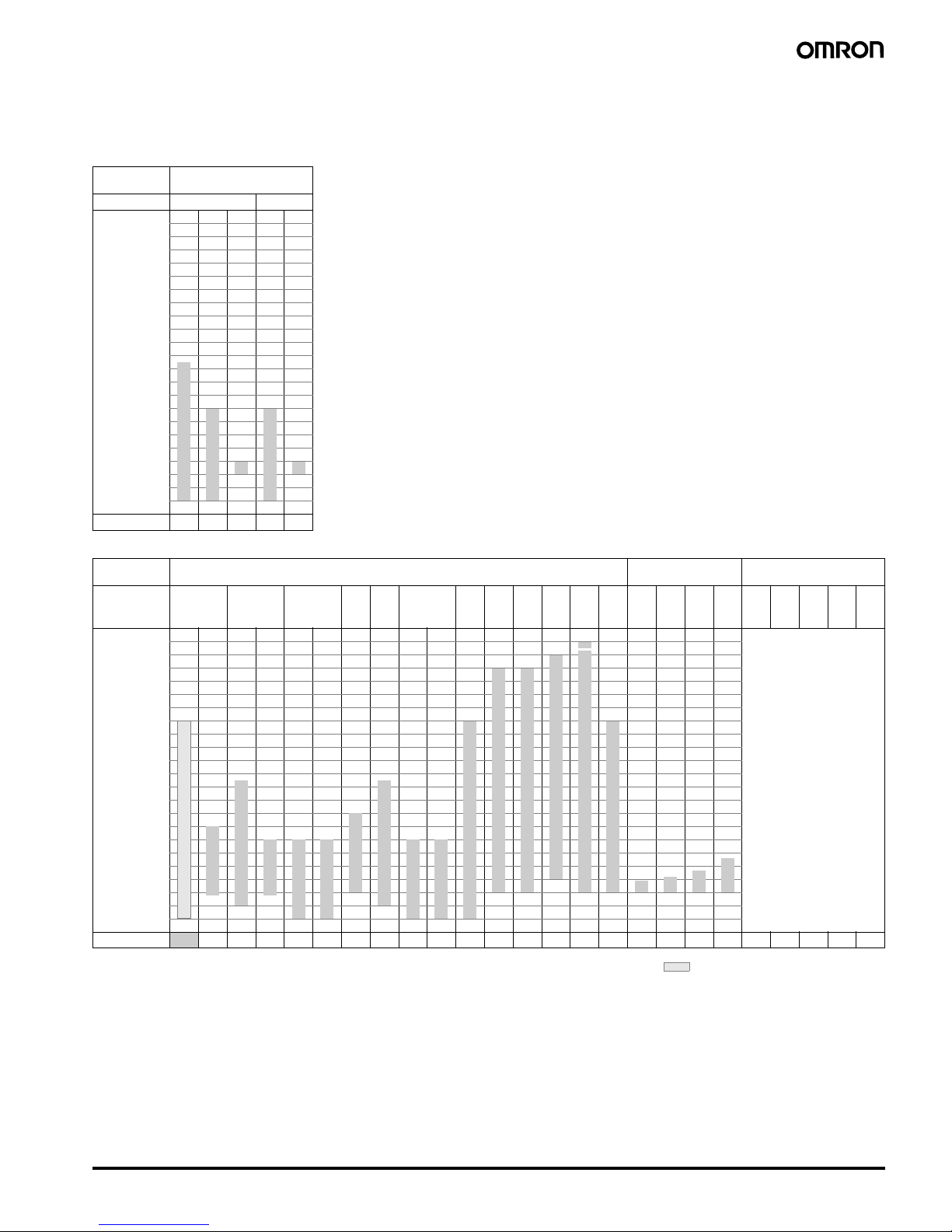
■ Input Ranges
Sensor inputs are fully multi-input. Therefore, platinum resistance thermometer, thermocouple, infrared thermosensor, and analog input can be
selected.
Inputs can be set for each channel using multi-inputs.
Input type Platinum resistance
thermometer
Name Pt100 JPt100
Tem perature
range
(°C)
2300
1800
1700
1600
1500
1400
1300
1200
1100
1000
900
800
700
600
500
400
300
200
100
0
−100.0
−200.0
850
500.0 500.0
100.0 1 00.0
0.0 0.0
−200 −199.9 −199.9
Setting number
01234
Input type Thermocouple ES1B Infrared
Thermosensor
Analog input
Name K J T E L U N R S B W PL
II
10
to
70
°C
60
to
120
°C
115
to
165
°C
140
to
260
°C
4 to
20
mA
0 to
20
mA
1 to
5 V
0 to
5 V
0 to
10 V
Tem perature
range
(°C)
2300
1800
1700
1600
1500
1400
1300
1200
1100
1000
900
800
700
600
500
400
300
200
100
0
−100.0
−200.0
2300
Any of the following ranges,
by scaling:
−1999 to 9999
−199.9 to 999.9
−19.99 to 99.99
−1.999 to 9.999
1800
1700 1700
1300 1300 1300
850 850
600
500.0
400.0 400 400.0 400 400.0
260
120 165
90
100
0 00 000000
−20.0 −100 −20.0 −100
−200 −200 −199.9 −200 −199.9 −200
Setting number
5 6 7 8 9 1011121314151617181920212223242526272829
Applicable standards by input type are as follows:
K, J, T, E, N, R, S, B: JIS C1602-1995, IEC584-1
L: Fe-CuNi, DIN 43710-1985
U: Cu-CuNi, DIN 43710-1985
W: W5Re/W26Re, ASTM E988-1990
PL II: According to Platinel II Electromotive Force
Table by Engelhard Cor p.
JPt100: JIS C 1604-1989, JIS C 1606-1989
Pt100: JIS C 1604-1997 IEC 751
Shaded ranges indicate default settings.
Page 6
6 Modular Temperature Controller EJ1
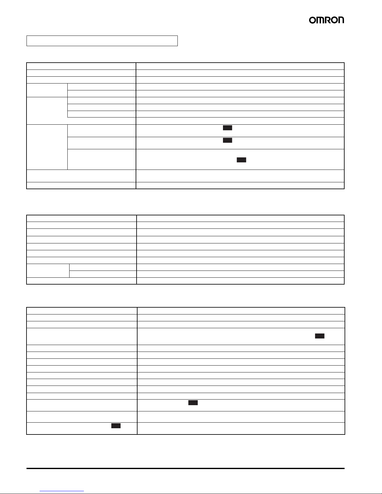
■ Ratings
Note: 1. Auxiliary outputs can be allocated using digital output allocations.
2. Event inputs can be allocated using digital output allocations.
■ Characteristics
■ Communications Characteristics: Port C
When using an HFU, port B on the End Plate can be used for distributed placement only.
Note: 1. The communications method can be switched between RS-485 and RS-232C. A separate model must be used for RS-422 communications.
2. For the number of Units that can be connected, refer to Connection Precautions on page 11.
HFU Unit/EJ1N-HFU
Power supply voltage 24 VDC
Operating voltage range 85% to 110% of rated voltage
Power consumption 2 W max. (at maximum load)
Auxiliary outputs
(See note 1.)
Outputs 4
Transistor outputs Max. operating voltage: 30 VDC, Max. load current: 50 mA
Event inputs (See
note 2.)
Inputs 4
Contact inputs ON: 1 k
Ω max., OFF: 100 kΩ min.
Transistor inputs ON: residual voltage of 1.5 max., OFF: leakage current of 0.1 mA max.
Short-circuit current: Approx. 4 mA (per contact)
Programless
connection
Programless downloading
(EJ1 reads data from a PLC)
Number of parameters that can be set: 600
300 (Ver. 1.0)
Programless uploading
(EJ1 writes data to a PLC)
Number of parameters that can be set: 600
300 (Ver. 1.0)
Applicable PLCs OMRON: SYSMAC CS/CJ/CP1H Series
Mitsubishi Electric: MELSEC-An/AnS/FX
3UC
Series
Mitsubishi Electric: MELSEC-Q/QnA/QnAS Series (Ver. 1.0)
Ambient temperature range Operating:
−10°C to 55°C
Storage:
−25°C to 65°C (with no icing or condensation)
Ambient humidity range Operating: 25% to 85% (with no condensation)
Insulation resistance 20 M
Ω min. (at 500 VDC)
Dielectric strength 600 VAC, 50/60 Hz for 1 min between current-carrying terminals of different polarity
Vibration resistance
10 to 55 Hz, 20 m/s
2
for 2 hours each in X, Y, and Z directions
Shock resistance
150 m/s
2
max., 3 times each in 6 directions
Weight 160 g
Degree of protection Rear case: IP20, Terminal section: IP00
Memory protection EEPROM (non-volatile memory) (number of writes: 100,000)
Standards Approved standards UL61010C-1, CSA C22.2 No.1010-1
Conformed standards EN61010-1 (IEC61010-1): Pollution level 2, overvoltage category II
EMC Directive Refer to page 3.
Transmission path connection RS-485/RS-422: Multi-point, RS-232C: Point-to-point (See note 1.)
Communications method RS-485/RS-422 (two-wire, half duplex), RS-232C
Synchronization method Star t-stop synchronization
Communications protocol • OMRON PLC protocol (Connectable PLCs: SYSMAC CS/CJ/CP1H Series)
• AnA/AnU CPU common commands (Connectable PLCs: MELSEC-An/AnS/FX
3UC
Series)
• MC protocol (form 5) (Connectable PLCs: MELSEC-Q/QnA/QnAS Series)
Baud rate 9.6, 19.2, 38.4, 57.6, or 115.2 kbps
Transmission code Binary
Data bit length 8 bits
Stop bit length 1 bit
Error detection Depends on protocol selected for the programless communications protocol.
Flow control None
Interface RS-485, RS-422, RS-232C (See note 1.)
Retry function Available
Communications response wait time 0 to 99 ms (default: 5 ms)
1 to 99 ms (default: 5 ms) (Ver. 1.0)
Number of Basic Units that can be connected in
parallel (See note 2.)
16 Units (model numbers with TC4: 64 channels, model numbers with TC2: 32 channels)
Number of HFUs that can be connected • SYSMAC CS/CJ-series PLCs: 8 (EJ1-HFU@-NFLK)
• MELEC Q/QnA/QnAS-series PLCs: 8 (EJ1-HFU@-NFL2 )
V1.1
V1.1
V1.1
V1.1
V1.1
V1.1
Page 7

Modular Temperature Controller EJ1 7
■ Ratings
Note: Auxiliary output can be allocated using the bus output allocation for each Basic Unit.
■ Characteristics
■ Communications
Note: 1. Port B communications for the End Unit cannot be used when port C communications for the HFU is used.
2. Port A connector communications and port A terminal communications cannot be used at the same time.
End Unit/EJ1C-EDU
Power supply voltage 24 VDC
Operating voltage range 85% to 110% of rated voltage
Auxiliary output
(See note.)
Outputs 2
Transistor outputs Max. operating voltage: 30 VDC, Max. load current: 50 mA
Ambient temperature range Operating:
−10°C to 55°C
Storage:
−25°C to 65°C (with no icing or condensation)
Ambient humidity range Operating: 25% to 85% (with no condensation)
Insulation resistance 20 M
Ω min. (at 500 VDC)
Dielectric strength 600 VAC, 50/60 Hz for 1 min between current-carrying terminals of different polarity
Vibration resistance
10 to 55 Hz, 20 m/s
2
for 2 hours each in X, Y, and Z directions
Shock resistance
150 m/s
2
max., 3 times each in 6 directions
Weight 70 g
Degree of protection End Unit case: IP20, Terminal section: IP00
Standards Approved standards UL61010C-1, CSA C22.2 No.1010-1
Conformed standards EN61010-1 (IEC61010-1): Pollution level 2, overvoltage category II
EMC Directive Same as for the Basic Unit. Refer to page 3.
Port B (See note 1.) Basic Unit Communications (Refer to Communications Specifications on page 4.)
Por t A Basic Unit Communications (Refer to Communications Specifications on page 4.)
Port A connector (See note 2.) E58-CIFQ1
Page 8
8 Modular Temperature Controller EJ1
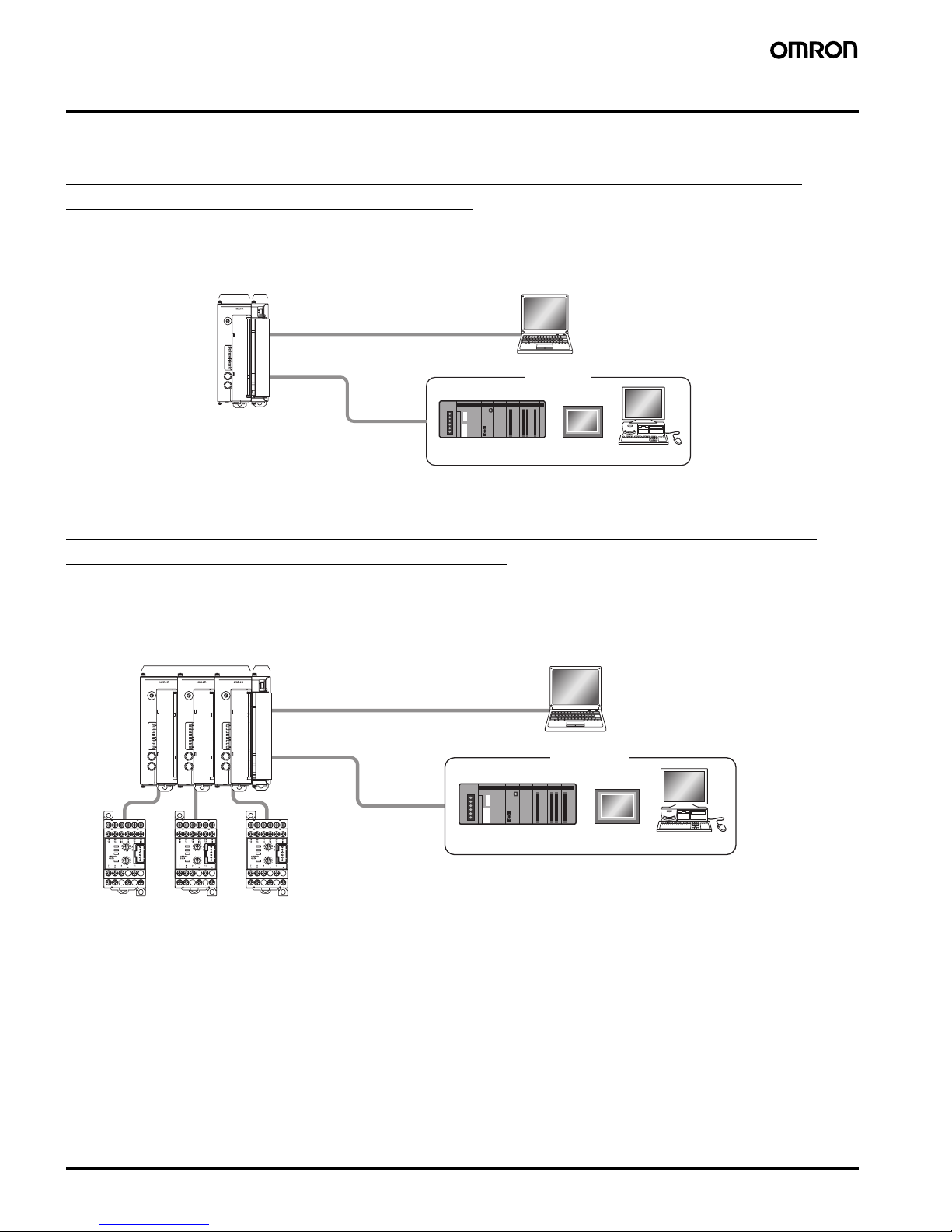
Unit Configuration Example
■ Minimal Configuration
Small Systems with 2 Channels or 4 Channels Communicating with the Host
Device via RS-485 (CompoWay/F Protocol)
• Alarms can be allocated to the auxiliary output for the End Unit.
• G3ZA outputs can be used.
■ Multiple Units without an EJ1N-HFU
Building Systems Communicating with the Host Device, such as a PLC, PT, or
Computer, via RS-485 (CompoWay/F Protocol)
• The 2 auxiliary alarm outputs (transistor outputs) provided on the End Unit can be used for integrated alarm systems.
• G3ZA outputs can be used.
• Distributed placement is possible by using multiple EJ1C-EDU End Units.
COM1
COM2
COM3
PWR
RUN
ERR
ALM
SW1
ON
SW2
21345678
EJ1-TC4
0
1
2
3
4
5
6
7
8
9
A
B
C
D
E
F
PC
PLC PT
PC
EJ1N-TC4
or
EJ1N-TC2 EJ1C-EDU
Port A (connector): USB connection can be made with the
E58-CIFQ1 (sold separately).
CX-Thermo for setting
Host devices
Port B: RS-485 (CompoWay/F)
SW2
SW1
ERROR
OCC
SD/RD
READY
G3ZA
PC
PLC PT
PC
EJ1N-TC4
or
EJ1N-TC2
EJ1C-EDU
Port B: RS-485 (CompoWay/F)
COM1
COM2
COM3
PWR
RUN
ERR
ALM
SW1
ON
SW2
21345678
EJ1-TC4
0
1
2
3
4
5
6
7
8
9
A
B
C
D
E
F
COM1
COM2
COM3
PWR
RUN
ERR
ALM
SW1
ON
SW2
21345678
EJ1-TC4
0
1
2
3
4
5
6
7
8
9
A
B
C
D
E
F
COM1
COM2
COM3
PWR
RUN
ERR
ALM
SW1
ON
SW2
21345678
EJ1-TC4
0
1
2
3
4
5
6
7
8
9
A
B
C
D
E
F
SW2
SW1
ERROR
OCC
SD/RD
READY
SW2
SW1
ERROR
OCC
SD/RD
READY
G3ZAG3ZA
Host devices
G3ZA
connection
port
G3ZA
connection
port
G3ZA
connection
port
CX-Thermo for setting
Port A (connector): USB connection can be made with
the E58-CIFQ1 (sold separately).
Page 9

Modular Temperature Controller EJ1 9
■ Multiple Units with an EJ1N-HFU
Building Systems Communicating 1:1 with a PLC Using Programless
Communications
• The 2 auxiliary outputs (transistor outputs) provided on the End Unit can be used.
• In addition to the 2 auxiliary alarm outputs provided on the End Unit, the 4 event inputs/4 auxiliary outputs (transistor outputs) of the HFU can
also be used.
• G3ZA outputs can be used.
• Distributed placement is possible by using multiple EJ1C-EDU End Units
SW2
SW1
ERROR
OCC
SD/RD
READY
G3ZA
SW2
SW1
ERROR
OCC
SD/RD
READY
SW2
SW1
ERROR
OCC
SD/RD
READY
G3ZAG3ZA
PC
EJ1N-HFU
PLC
EJ1N-TC4
or
EJ1N-TC2 EJ1C-EDU
Por t B
RS-232C
Port B is used for distributed placement.
Port A (connector): USB connection can be made with the
E58-CIFQ1 (sold separately).
COM1
COM2
COM3
PWR
RUN
ERR
ALM
SW1
ON
SW2
21345678
EJ1-TC4
0
1
2
3
4
5
6
7
8
9
A
B
C
D
E
F
COM1
COM2
COM3
PWR
RUN
ERR
ALM
SW1
ON
SW2
21345678
EJ1-TC4
0
1
2
3
4
5
6
7
8
9
A
B
C
D
E
F
COM1
COM2
COM3
PWR
RUN
ERR
ALM
SW1
ON
SW2
21345678
EJ1-TC4
0
1
2
3
4
5
6
7
8
9
A
B
C
D
E
F
COM1
COM2
COM3
PWR
RUN
ERR
ALM
SW1
ON
SW2
21345678
EJ1-HFU
0
1
2
3
4
5
6
7
8
9
A
B
C
D
E
F
CX-Thermo for setting
G3ZA
connection port
G3ZA
connection
port
Por t C
G3ZA
connection
port
Page 10

10 Modular Temperature Controller EJ1
Building Systems Communicating 1:N with PLCs Using Programless
Communications
• Up to eight HFUs can be connected to one port on a PLC.
• To connect more than one HFU, specific PLC and EJ1 models must be used. Refer to Connecting EJ1 Controllers 1:N to a PLC on page 13.
V1.1
SW2
SW1
ERROR
OCC
SD/RD
READY
G3ZA
SW2
SW1
ERROR
OCC
SD/RD
READY
SW2
SW1
ERROR
OCC
SD/RD
READY
G3ZAG3ZA
Up to eight HFUs can be connected.
PC
EJ1N-HFU
PLC
EJ1N-TC4
or
EJ1N-TC2
EJ1C-EDU
Por t B
Port B is used for distributed placement.
Port A (connector): USB connection can be made with the
E58-CIFQ1 (sold separately).
COM1
COM2
COM3
PWR
RUN
ERR
ALM
SW1
ON
SW2
21345678
EJ1-TC4
0
1
2
3
4
5
6
7
8
9
A
B
C
D
E
F
COM1
COM2
COM3
PWR
RUN
ERR
ALM
SW1
ON
SW2
21345678
EJ1-TC4
0
1
2
3
4
5
6
7
8
9
A
B
C
D
E
F
COM1
COM2
COM3
PWR
RUN
ERR
ALM
SW1
ON
SW2
21345678
EJ1-TC4
0
1
2
3
4
5
6
7
8
9
A
B
C
D
E
F
COM1
COM2
COM3
PWR
RUN
ERR
ALM
SW1
ON
SW2
21345678
EJ1-HFU
0
1
2
3
4
5
6
7
8
9
A
B
C
D
E
F
CX-Thermo for setting
Por t C
SYSMAC (OMRON PLC) RS-485
MELSEC (Mitsubishi Electric PLC) RS-422
G3ZA
connection
port
G3ZA
connection
port
G3ZA
connection
port
G3ZA
connection
port
G3ZA
connection
port
G3ZA
connection
port
SW2
SW1
ERROR
OCC
SD/RD
READY
G3ZA
SW2
SW1
ERROR
OCC
SD/RD
READY
SW2
SW1
ERROR
OCC
SD/RD
READY
G3ZAG3ZA
EJ1N-HFU
EJ1N-TC4
or
EJ1N-TC2
EJ1C-EDU
COM1
COM2
COM3
PWR
RUN
ERR
ALM
SW1
ON
SW2
21345678
EJ1-TC4
0
1
2
3
4
5
6
7
8
9
A
B
C
D
E
F
COM1
COM2
COM3
PWR
RUN
ERR
ALM
SW1
ON
SW2
21345678
EJ1-TC4
0
1
2
3
4
5
6
7
8
9
A
B
C
D
E
F
COM1
COM2
COM3
PWR
RUN
ERR
ALM
SW1
ON
SW2
21345678
EJ1-TC4
0
1
2
3
4
5
6
7
8
9
A
B
C
D
E
F
COM1
COM2
COM3
PWR
RUN
ERR
ALM
SW1
ON
SW2
21345678
EJ1-HFU
0
1
2
3
4
5
6
7
8
9
A
B
C
D
E
F
Por t C
Note: Set the EJ1N-TC to a communications unit number that is not being used by the EJ1N-HFU.
Page 11

Modular Temperature Controller EJ1 11
■ Connection Precautions
Node Number Setting
• Nodes 1 to 16 can be used on EJ1@-HFUs. Node 0 is allocated to
the host device for programless communications.
• Nodes 0 to 63 can be used on Basic Units.
Restrictions on the Number of Units
That Can Be Connected
Restrictions for HFUs
• One EJ1N-HFU can manage up to 16 Basic Units (EJ1N-TC4/
TC2).
• Up to 16 Units can be connected side by side including the EJ1NHFU. The End Unit is not included in the 16 Units.
Restrictions When Connecting with the
G3ZA
• Up to 8 G3ZA Multi-channel Power Controllers can be connected to
one Basic Unit (EJ1N-TC4/TC2).
Restrictions for Basic Units
• When the system is configured of only Basic Units (EJ1N-TC4/
TC2), up to 64 Units can be connected.
• Distributed placement is possible by using End Units (EJ1C-EDU).
• Up to 16 Units can be connected side by side. The End Unit is not
included in the 16 Units.
Wiring for Distributed Placement
Note: Wire the dotted line when settings for all distributed Units are
being made from one port A connector.
If the dotted lines are not wired, make the settings for group A
using the port A connector for group A and make the settings
for group B using the port A connector for group B.
COM1
COM2
COM3
PWR
RUN
ERR
ALM
SW1
ON
SW2
21345678
EJ1-TC4
0
1
2
3
4
5
6
7
8
9
A
B
C
D
E
F
COM1
COM2
COM3
PWR
RUN
ERR
ALM
SW1
ON
SW2
21345678
EJ1-TC4
0
1
2
3
4
5
6
7
8
9
A
B
C
D
E
F
COM1
COM2
COM3
PWR
RUN
ERR
ALM
SW1
ON
SW2
21345678
EJ1-TC4
0
1
2
3
4
5
6
7
8
9
A
B
C
D
E
F
COM1
COM2
COM3
PWR
RUN
ERR
ALM
SW1
ON
SW2
21345678
EJ1-TC4
0
1
2
3
4
5
6
7
8
9
A
B
C
D
E
F
COM1
COM2
COM3
PWR
RUN
ERR
ALM
SW1
ON
SW2
21345678
EJ1-HFU
0
1
2
3
4
5
6
7
8
9
A
B
C
D
E
F
COM1
COM2
COM3
PWR
RUN
ERR
ALM
SW1
ON
SW2
21345678
EJ1-TC4
0
1
2
3
4
5
6
7
8
9
A
B
C
D
E
F
EJ1N-TC4 or
EJ1N-TC2
One HFU can manage up to 16 Basic Units
(when using the EJ1N-TC4: 4 channels x 16 Units = 64 channels)
EJ1C-EDU
EJ1C-EDU
Por t B
Por t B
EJ1N-HFU
Por t C
EJ1N-TC4
or
EJ1N-TC2
Up to 16 Units can be connected side by side.
Note: End Units are not included in the number
of Units that can be connected.
To the host device
COM1
COM2
COM3
PWR
RUN
ERR
ALM
SW1
ON
SW2
21345678
EJ1-TC4
0
1
2
3
4
5
6
7
8
9
A
B
C
D
E
F
EJ1C-EDU
Up to 8 G3ZA Power Controllers can be connected to one Basic Unit.
EJ1N-TC4 or EJ1N-TC2
G3ZA
G3ZA connection port
SW2
SW1
ERROR
OCC
SD/RD
READY
SW2
SW1
ERROR
OCC
SD/RD
READY
SW2
SW1
ERROR
OCC
SD/RD
READY
SW2
SW1
ERROR
OCC
SD/RD
READY
Por t B
To the host device
Por t B
COM1
COM2
COM3
PWR
RUN
ERR
ALM
SW1
ON
SW2
21345678
EJ1-TC4
0
1
2
3
4
5
6
7
8
9
A
B
C
D
E
F
COM1
COM2
COM3
PWR
RUN
ERR
ALM
SW1
ON
SW2
21345678
EJ1-TC4
0
1
2
3
4
5
6
7
8
9
A
B
C
D
E
F
COM1
COM2
COM3
PWR
RUN
ERR
ALM
SW1
ON
SW2
21345678
EJ1-TC4
0
1
2
3
4
5
6
7
8
9
A
B
C
D
E
F
COM1
COM2
COM3
PWR
RUN
ERR
ALM
SW1
ON
SW2
21345678
EJ1-TC4
0
1
2
3
4
5
6
7
8
9
A
B
C
D
E
F
COM1
COM2
COM3
PWR
RUN
ERR
ALM
SW1
ON
SW2
21345678
EJ1-TC4
0
1
2
3
4
5
6
7
8
9
A
B
C
D
E
F
COM1
COM2
COM3
PWR
RUN
ERR
ALM
SW1
ON
SW2
21345678
EJ1-TC4
0
1
2
3
4
5
6
7
8
9
A
B
C
D
E
F
EJ1C-EDU
EJ1N-TC4 or EJ1N-TC2
COM1
COM2
COM3
PWR
RUN
ERR
ALM
SW1
ON
SW2
21345678
EJ1-TC4
0
1
2
3
4
5
6
7
8
9
A
B
C
D
E
F
COM1
COM2
COM3
PWR
RUN
ERR
ALM
SW1
ON
SW2
21345678
EJ1-TC4
0
1
2
3
4
5
6
7
8
9
A
B
C
D
E
F
COM1
COM2
COM3
PWR
RUN
ERR
ALM
SW1
ON
SW2
21345678
EJ1-TC4
0
1
2
3
4
5
6
7
8
9
A
B
C
D
E
F
COM1
COM2
COM3
PWR
RUN
ERR
ALM
SW1
ON
SW2
21345678
EJ1-TC4
0
1
2
3
4
5
6
7
8
9
A
B
C
D
E
F
COM1
COM2
COM3
PWR
RUN
ERR
ALM
SW1
ON
SW2
21345678
EJ1-TC4
0
1
2
3
4
5
6
7
8
9
A
B
C
D
E
F
COM1
COM2
COM3
PWR
RUN
ERR
ALM
SW1
ON
SW2
21345678
EJ1-TC4
0
1
2
3
4
5
6
7
8
9
A
B
C
D
E
F
EJ1C-EDU
EJ1N-TC4 or EJ1N-TC2
Up to 64 Basic Units can be connected using distributed placement.
Using EJ1@-TC4 models: 4 channels x 64 Units = 256 channels
Using EJ1@-TC2 models: 2 channels x 64 Units = 128 channels
Note: End Units are not included in the number of Units that can be connected.
COM1
COM2
COM3
PWR
RUN
ERR
ALM
SW1
ON
SW2
21345678
EJ1-TC4
0
1
2
3
4
5
6
7
8
9
A
B
C
D
E
F
COM1
COM2
COM3
PWR
RUN
ERR
ALM
SW1
ON
SW2
21345678
EJ1-TC4
0
1
2
3
4
5
6
7
8
9
A
B
C
D
E
F
1
2
3
4
5
6
7
8
9
Group A
Group B
COM1
COM2
COM3
PWR
RUN
ERR
ALM
SW1
ON
SW2
21345678
EJ1-TC4
0
1
2
3
4
5
6
7
8
9
A
B
C
D
E
F
COM1
COM2
COM3
PWR
RUN
ERR
ALM
SW1
ON
SW2
21345678
EJ1-TC4
0
1
2
3
4
5
6
7
8
9
A
B
C
D
E
F
1
2
3
4
5
6
7
8
9
Por t A
Por t B
Por t A
Por t B
Host
devices
FG
24 VDC
RS-485
RS-485
24 VDC
Page 12

12 Modular Temperature Controller EJ1
Restrictions on Unit Placement
Always connect the HFU on the left side of the Basic Unit. Do not connect the End Unit directly to the HFU.
Always connect a Basic Unit to the End Unit.
■ Insulation Blocks
Each EJ1 Unit is electrically insulated for each function block as shown in the following figures.
Functional insulation is applied between the power supply, input, output, and communications terminal sections.
If reinforced double insulation is required, use power supplies that comply with IEC60664 for reinforced double insulation for the EJ1's external
power supply and for power supplies connected to the EJ1.
■ Programless Communications
Communications with PLCs from OMRON (SYSMAC CS/CJ/CP1H Series) and Mitsubishi Electric (MELSEC-Q/QnA/QnAS/An/Ans/FX
3UC
Series)
can be performed without creating ladder programming.
Using programless communications enables monitoring and changing settings for the EJ1 by simply reading and writing to PLC memory.
The EJ1 automatically performs communications with the PLC, which reduces work hours spent programming for communications from the PLC
to the EJ1.
Connectable Devices
Connecting an EJ1 Controller 1:1 to a PLC
SYSMAC CS/CJ Series
Note: Use only products manufactured on or after December 20, 1999.
For details, refer to the CS/CJ Series, Serial Communications Boards Operation Manual (Cat. No. W336).
COM1
COM2
COM3
PWR
RUN
ERR
ALM
SW1
ON
SW2
21345678
EJ1-HFU
0
1
2
3
4
5
6
7
8
9
A
B
C
D
E
F
COM1
COM2
COM3
PWR
RUN
ERR
ALM
SW1
ON
SW2
21345678
EJ1-TC4
0
1
2
3
4
5
6
7
8
9
A
B
C
D
E
F
EJ1N-HFUEJ1N-TC4 or
EJ1N-TC2
COM1
COM2
COM3
PWR
RUN
ERR
ALM
SW1
ON
SW2
21345678
EJ1-HFU
0
1
2
3
4
5
6
7
8
9
A
B
C
D
E
F
EJ1N-HFU EJ1C-EDU
Name Model No. Communications ports
Por t 1 Port 2
Serial Communications Units CJ1W-SCU21-V1 RS-232C RS-232C
CJ1W-SCU31-V1 RS-422A/485 RS-422A/485
CJ1W-SCU41-V1 RS-422A/485 RS-232C
CS1W-SCU21-V1 (See note.) RS-232C RS-232C
CS1W-SCU31-V1 RS-422A/485 RS-422A/485
Serial Communications Boards CS1W-SCB21-V1 (See note.) RS-232C RS-232C
CS1W-SCB41-V1 (See note.) RS-232C RS-422A/485
CPU Units CJ1 Series --- RS-232C
CS1 Series --- RS-232C
CP1H Series RS-232C or RS-422A/485 can be used by adding an Option Board.
Powe r
supply
Transistor outputs 1 to 4
Communications (Port B, port C)
Event inputs 1 to 4
Functional isolation
Powe r
supply
Transistor outputs 1 and 2
Communications (Port A, port B)
Functional isolation
EJ1N-HFU
Input 1
Powe r
supply
Input 2
Event inputs 1 and 2, CT1 and 2
(See note.)
Communications (Port A, port B, G3ZA)
Transistor outputs 3 and 4
Voltage outputs 1 and 2/Current outputs 1 and 2
Functional isolation
Input 1
Powe r
supply
Input 2
Input 4
Voltage outputs 1 to 4
Communications (Port A, Port B, G3ZA)
Input 3
Functional isolation
EJ1N-TC2 EJ1N-TC4
EJ1C-EDU
Note: Not provided on models with current outputs.
PV
PLC
The read monitor value is
written to the PLC memory.
The read setting is written to the
setting for the EJ1N-TC4/TC2.
Manipulated variable
Status
SP
Monitor
Setting
Alarm value 1
Alarm value 2
EJ1N-HFU EJ1N-TC4/TC2
The EJ1N-HFU automatically
performs communications
with the PLC.
The EJ1N-HFU reads the value
written to the PLC memory.
The EJ1N-HFU reads the monitor
value for the EJ1N-TC4/TC2.
Monitoring can be
performed for the
EJ1 and the settings
can be changed by
simply reading and
writing to memory.
PV
Manipulated variable
Status
SP
Alarm value 1
Alarm value 2
PV
Manipulated variable
Status
SP
Alarm value 1
Alarm value 2
Page 13

Modular Temperature Controller EJ1 13
MELSEC-Q/QnA/QnAS Series
Note: 1. Refer to the Mitsubishi Electric PLC documentation for information on MELSEC PLCs.
2. Direct connections to the EJ1 are possible only with RS-232C or RS-422.
3. More than one EJ1 Controller to one PLC is not possible even with RS-422 communications. Refer to
Connecting EJ1 Controllers 1:N to a PLC,
below, for product combinations that support 1:N connections
.
4. Connection ability has been verified for the above MELSEC models. Design changes and other factors, however, may prevent normal connection.
Always confirm operation in advance.
MELSEC-An/AnS Series
Note: Use an AnA/AnU CPU.
MELSEC-FX
3UC
Series
Connecting EJ1 Controllers 1:N to a PLC
The combinations of PLCs and HFUs that can be connected 1:N are listed below.
SYSMAC CS/CJ Series
MELSEC-Q/QnA/QnAS Series
Note: Refer to the Mitsubishi Electric PLC documentation for information on MELSEC PLCs.
Name Model No. Communications por ts
Channel 1 Channel 2
Q-compatible Serial
Communications Unit
QJ71C24N
QJ71C24
RS-232C RS-422/485
QJ71C24N-R2
QJ71C24-R2
RS-232C RS-232C
QJ71C24N-R4 RS-422/485 RS-422/485
QnA-compatible Serial
Communications Unit
AJ71QC24N RS-232C RS-422/485
AJ71QC24N-R2 RS-232C RS-232C
AJ71QC24N-R4 RS-422 RS-422/485
QnAS-compatible Serial
Communications Unit
A1SJ71QC24N RS-232C RS-422/485
A1SJ71QC24N-R2 RS-232C RS-232C
V1.1
Name Model No. Communications ports
An-compatible Computer Link Unit AJ71UC24 RS-232C or RS-422/485
AnS-compatible Computer Link Unit A1SJ71UC24-R2 RS-232C
A1SJ71UC24-R4 RS-422/485
A1SJ71UC24-PRF RS-232C
V1.1
Name Model No. Communications ports
Communications Adapter FX
3U
-232ADP RS-232C
FX
3U
-485ADP RS-485
Function Board FX
3U
-232-BD RS-232C
FX
3U
-485-BD RS-485
Name Model No.
Serial Communications Units Port 1 on CJ1W-SCU31-V1
Port 1 on CJ1W-SCU41-V1
Port 1 on CS1W-SCU31-V1
Serial Communications Board Port 1 on CS1W-SCB41-V1
EJ1N-HFU EJ1N-HFUA-NFLK
EJ1N-HFUB-NFLK
Name Model No.
Serial Communications Units Channel 2 of QJ71C24N
QJ71C24N-R4
Channel 2 of A1SJ71QC24N
Channel 2 of AJ71QC24N
AJ71QC24N-R4
EJ1N-HFU EJ1N-HFUA-NFL2
EJ1N-HFUB-NFL2
V1.1
Page 14

14 Modular Temperature Controller EJ1
Connection
■ External Connection
• Functional insulation is applied between the power supply and the I/O sections. If reinforced insulation is required, connect the input
and output terminals to devices without any exposed current-carrying parts or to devices with reinforced insulation suitable for the
maximum operating voltage of the power supply and I/O sections.
• To comply with the standards for noise terminal voltage for class A in EN 61326, install a noise filter (Densei Lamda MXB-1206-33 or
the equivalent) to the DC power line as close as possible to the Temperature Controller.
• Use an SELV power supply. An SELV circuit is one separated from the power supply with double insulation or reinforced insulation,
that does exceed an output voltage of 30 V r.m.s. and 42.4 V peak or 60 VDC max. The OMROM S8VS Series is recommended for the
power supply.
EJ1N-TC4 EJ1N-TC2
EJ1N-HFU EJ1C-EDU
Note: 1. To connect to the G3ZA, separately purchase a G3ZA Connecting Cable (EJ1C-CBLA050) and connect it to the G3ZA connection port (CN1) on the EJ1.
2. To connect to a computer using the port A connector, use a separately sold E58-CIFQ1 USB-Serial Conversion Cable. The Temperature Controller can be
connected to a computer using USB.
3. Models with screw-less clamp terminals have terminals A10 and B10, but they are not used. Do not connect anything to them.
12 VDC
12 VDC
OUT4
OUT3
12 VDC
12 VDC
OUT2
OUT1
B1
B2
B3
B4
B5
B6
B7
B8
B9
A1
A2
A3
A4
A5
A6
A7
A8
A9
CH4
CN1
G3ZA connection port
Analog
input
Pt Thermo-
couple
A
B
B
mA
V
CH3
A
B
B
mA
V
CH2
A
B
B
mA
V
CH1
A
B
B
mA
V
Circuit 1
Circuit 1
OUT4
OUT3
B1
B2
B3
B4
B5
B6
12 VDC
Models with
pulse outputs
Models with
linear outputs
12 VDC
B7
B8
B9
CN1
OUT2
OUT1
4 to 20 mA DC/0 to 20 mA
4 to 20 mA DC/0 to 20 mA
OUT2
OUT1
A1
A2
A3
A4
A5
A6
EV2
EV1
A7
A8
A9
CT2
CT1
Circuit 1
∗
Circuit 2
Circuit 3
G3ZA connection port
CH2
A
B
B
mA
V
CH1
A
B
B
mA
V
Analog
input
Pt Thermo-
couple
Not provided
on models
with linear
output.
Provided only
on models
with pulse
output.
RS-485RS-422
Not used
Not used
Not used
SUB2
SUB1
RS-232C
RS-422
SD
RD
SG
B1
B2
B3
B4
B5
B6
SUB4
SUB3
B7
B8
B9
B (+)
A (−)
RDB (+)
RDA (−)
SDB (+)
SDA (−)
A1
A2
A3
A4
A5
A6
A7
A8
A9
Circuit 2
Circuit 3
Circuit 2
Circuit 3
Por t C
Por t C
RS-485 for port C and RS-232C
can be switched.
A separate EJ1 model must be used for
RS-422 communications.
EV2
EV1
EV4
EV3
Input power suppl
y
Port A connector
Por t B
Por t A
These two ports
cannot be used
at the same time.
Cannot be used
when an HFU is used.
B
A
B
A
24 VDC
SUB2
SUB1
1
2
3
4
5
6
7
8
9
RS-485
RS-485
Circuit 2
Page 15

Modular Temperature Controller EJ1 15
■ Internal Wiring
Circuit 1
*Models with Pulse Outputs)
Circuit 2
Circuit 3
Nomenclature and Specification Settings
■ Nomenclature
Operation Indicators
EJ1N-TC2/TC4
EJ1N-HFU
Note: A certain period of time is required for the indicators to light
after the power is turned ON.
L
+V
GND
B1/B2
EJ1N
-TC4
B3
L
B1/B2
EJ1N
-TC2
B3
A1/A2
EJ1N
-TC4
A3
L
A1/A2
EJ1N
-TC2
A3
B1/B2
EJ1N
-HFU
B3
B4/B5
EJ1N
-HFU
B6
3/4
EJ1C
-EDU
5
+V
GND
A6
A4/A5
EJ1N
-TC2
A3
A1/A2
EJ1N
-HFU
A6
A4/A5
EJ1N
-HFU
COM1
COM2
COM3
EJ1-
PWR
RUN
ERR
ALM
SW1
ON
SW2
21345678
0
1
2
3
4
5
6
7
8
9
A
B
C
D
E
F
Operation
Indicators
COM1
COM2
COM3
Operation
Indicators
PWR
RUN
ERR
ALM
SW1
SW2
Operation
Indicators
Meaning
PWR (green) Lit while the power is ON.
RUN (green) Lit during operation.
ERR (red) Flashes or lights when an error occurs.
ALM (red) Lights when an alarm is activated.
COM 1 (orange) Flashes during communications using port A on
the End Unit.
COM 2 (orange) Flashes during communications using port B on
the End Unit.
COM 3 (orange) Flashes during communications with the G3ZA.
Operation
Indicators
Meaning
PWR (green) Lit while the power is ON. (See note.)
RUN (green) ---
ERR (red) Flashes or lights when an error occurs.
ALM (red) Lights when an alarm is activated.
COM 1 (orange) Flashes during communications using port A on
the End Unit.
COM 2 (orange) Flashes when the EJ1 system is in operation.
COM 3 (orange) Flashes during communications using port C.
Page 16

16 Modular Temperature Controller EJ1
■ Specification Settings
Switch Operation
• Check that the EJ1 is turned OFF before operating the switches.
Settings are read only when power is turned ON.
• Set the switches with a small flat-blade screwdriver. Do not set the
switches midway between settings.
• SW1 is set to 1 and SW2 pins are all set to OFF in the default
settings.
Setting the Unit Number
SW1 and SW2 are used together to set the unit number to between
00 and 63. The factory setting is unit number 01.
SW2 Settings
EJ1N-TC2/TC4
EJ1N-HFU
SW2 SW1
1 2 0123456789ABCDEF
OFF OFF
00 01 02 03 04 05 06 07 08 09 10 11 12 13 14 15
ON OFF
16 17 18 19 20 21 22 23 24 25 26 27 28 29 30 31
OFF ON
32 33 34 35 36 37 38 39 40 41 42 43 44 45 46 47
ON ON
48 49 50 51 52 53 54 55 56 57 58 59 60 61 62 63
0
1
2
3
4
5
6
7
8
9
A
B
C
D
E
F
ON
21345678
SW1 SW2
SW2 Meaning
3 to 6 Not used (OFF)
7 ON: G3ZA in operation
8 Use when an HFU is used and Units are
distributed.
(Refer to the operation manual for details.)
SW2 Meaning
3 to 7 Not used (OFF)
8•EJ1N-HFU@-NFLK
OFF: RS-485 is selected.
ON: RS-232C is selected.
• EJ1N-HFU@-NFL2
OFF (Not used.)
Page 17

Modular Temperature Controller EJ1 17
Functional Upgrades
The following mark is used to indicate descriptions of upgraded functions: .
The functional upgrades are as follows:
Basic Units (EJ1N-TC4/2)
• Modbus communications can be used on port B.
• Software version 2 of G3ZA Multi-channel Power Controller can be used.
Note: Software version 2 of G3ZA Multi-channel Power Controller can also be used with EJ1 version 1.0.
HFUs (EJ1N-HFU)
• Programless communications can be used with 1:N connections.
• The maximum number of parameters that can be specified for programless up/down setting has been increased to 600 each.
• Connection now possible to MELSEC-QnA/An/AnS/FX3uc-series PLCs.
• A new setting read operation has been added to programless communications: Setting Read 2.
• The speed of programless communications has been increased.
• Either “continue” or “stop” can be selected for when errors occur in programless communications.
Support Software
Use version 3.20 or higher of the CX-Thermo when using the upgraded functions.
Identifying Upgraded Models
The new functionality can be used with version 1.1 (V1.1). Check the label on the Temperature Controller or the box to determine the version.
Models not marked “Ver. 1.1” are version 1.0.
Box Label
Temperature Controller Label
V1.1
V1.1
Version
Version
Page 18

18 Modular Temperature Controller EJ1
Dimensions
Note: All units are in millimeters unless otherwise indicated.
■ Temperature Controller
Basic Uni
ts
EJ1N-TC
HFUs
EJ1N-HFU
0
1
2
3
4
5
6
7
8
9
A
B
C
D
E
F
COM1
COM2
COM3
PWR
RUN
ERR
ALM
SW1
ON
SW2
21345678
0
1
2
3
4
5
6
7
8
9
A
B
C
D
E
F
COM1
COM2
COM3
EJ1N-EJ1N-
PWR
RUN
ERR
ALM
SW1
ON
SW2
21345678
109 (Models with screw terminal blocks)
104.85 (Models with screw-less clamp
terminal blocks)
27.
0
35.
4
27.
6
9095.4
31
Models with screw
terminal blocks
31
Models with screw-less
clam
p
terminal blocks
76.2
60
15.7
9095.4
27.0
35.4
27.6
End Units
EJ1C-EDU
Page 19

Modular Temperature Controller EJ1 19
■ Options
Current Transformer (Sold Separately)
40@
30
12 dia.
9
2.36 dia.
15
30
Two, M3 (depth: 4)
E54-CT3
Plug
Armature
Lead
30
21
15
5.8 dia.
25
3
40
10.5
2.8
7.5
10
Two, 3.5 dia.
E54-CT1
Connection Example
Approx. 3 dia.
18
(22)
Approx. 6 dia.
E54-CT3 Accessory
• Armature
• Plug
Rail Mounting Equipment (Order Separately)
DIN Rail
PFP-100N
PFP-50N
Note: The figures in parentheses
are dimensions for the
PFP-50N.
4.5
15 25 25
10 10
1000 (500)
(See note.)
25 25 15 (5)
(See note.)
35
±0.3
7.3±0.15
27±0.1
5
1
50
11.5
10
M4 × 8
panhead
screw
M4 spring washer 4.8
1.3
1.8
1
10
6.2
1.8
35.5 35.
3
End Plate
PFP-M
Note: Two screws are included with the EJ1C-EDU for the End Plate.
Always attach End Plates to both sides.
Page 20

20 Modular Temperature Controller EJ1
I/O Devices
■ Examples of EJ1-series Temperature Controllers/Output Devices
SW2
SW1
ERROR
OCC
SD/RD
READY
G3ZA
SSR SSR
Eight Units max.∗
SSR SSR
COM1
COM2
COM3
PWR
RUN
ERR
ALM
SW1
ON
SW2
21345678
EJ1-TC2
0
1
2
3
4
5
6
7
8
9
A
B
C
D
E
F
COM1
COM2
COM3
PWR
RUN
ERR
ALM
SW1
ON
SW2
21345678
EJ1-TC2
0
1
2
3
4
5
6
7
8
9
A
B
C
D
E
F
COM1
COM2
COM3
PWR
RUN
ERR
ALM
SW1
ON
SW2
21345678
EJ1-TC2
0
1
2
3
4
5
6
7
8
9
A
B
C
D
E
F
COM1
COM2
COM3
PWR
RUN
ERR
ALM
SW1
ON
SW2
21345678
EJ1-TC2
0
1
2
3
4
5
6
7
8
9
A
B
C
D
E
F
COM1
COM2
COM3
PWR
RUN
ERR
ALM
SW1
ON
SW2
21345678
EJ1-TC2
0
1
2
3
4
5
6
7
8
9
A
B
C
D
E
F
COM1
COM2
COM3
PWR
RUN
ERR
ALM
SW1
ON
SW2
21345678
EJ1-TC2
0
1
2
3
4
5
6
7
8
9
A
B
C
D
E
F
EJ1
G3ZA
Multi-channel Power Controller
EJ1N-TC2@-QNHB
EJ1N-TC4
Temperature controller
Voltage output
terminal
(for driving SSR)
SSR
INPUT LOAD
Load
Heater
Load
power
supply
G3PC (SSR with failure detection)
Ultra-compact and slim
model combined with a
heat radiator
Rated input voltage:
12 to 24 VDC
3
3
3
2
Converters, Digital Panel Meters, Flow Meters,
Infrared Thermosensors, Displacement Sensors
240 VAC, 20 A
240 VAC, 10 A, 20 A, 40 A, or 60 A
400 or 480 VAC, 20 A, 30 A, or 50 A
240 VAC, 5 A, 10 A, 20 A, 40 A, 75 A, or 90 A
480 VAC, 10 A, 20 A, 40 A, 75 A, or 90 A
A
G
H
T
U
OMRON
A
G
H
T
U
R
W
N
B
V
C
D
S
IO
L
H
G
F
A
G
H
T
U
R
W
N
B
V
C
D
S
IO
L
H
G
F
A
G
H
T
U
R
W
N
B
V
C
D
S
IO
L
H
G
F
AGHTURWNBVC
AGHTURWNBVC
A
G
H
T
U
A
A
A
A
O
M
R
O
N
A
G
H
T
U
R
W
N
B
V
C
AGHTUR
AG
AG
A
G
H
T
A
G
H
T
U
R
W
N
B
V
C
D
S
AG
HTU
RW
NBVC
DS
AG
HTURW
NBVCD
S
A
G
H
T
U
R
W
N
B
V
C
D
S
AGHTURW
AGHTURW
AGHTURW
A
G
H
T
A
G
H
T
U
R
W
N
B
V
C
D
S
A
G
H
T
A
G
H
T
AGHT
AGHT
AGHT
AGHT
AGHT
AGHT
AGHT
AGHT
AGHT
A
G
H
T
U
R
W
N
B
V
C
D
S
G3PB (Single Phase)
Ultra-compact and slim
model combined with a
heat radiator
Rated input voltage:
12 to 24 VDC
240 VAC, 15 A, 25 A, 35 A, or 45 A
480 VAC, 15 A, 25 A, 35 A, or 45 A
G3PB (Three Phase)
Three-phase batch
control combined with
heat radiator
Rated input voltage:
12 to 24 VDC
240, 400, or 480 VAC, 15 A, 25 A, 35 A, or 45 A
G3PA
Ultra-compact and slim
model combined with a
heat radiator
Rated input voltage:
240 V: 5 to 24 VDC
400/480 V: 12 to 24 VDC
Analog quantities, such as temperature,
flow rate, and concentration
ES1B
Infrared Thermosensor
Thermocouple/Platinum
Resistance Thermometer E52
G3NA
Standard model
with screw terminals
Rated input voltage:
5 to 24 VDC
G3NE
Rated input voltage:
12 VDC
240 VAC, 5 A, 10 A, or 20 A
3
∗The G3ZA is available with 4 or 8 control
p
oints.
4
G3NH
For high-power
heater control
Rated input voltage:
5 to 24 VDC
240 or 440 VAC, 75 A or 150 A
Input device/sensor
Can be directly
connected.
1
Special Cable
(Communication)
ES2-HB Humidity Sensor
ES2-THB Temperature/Humidity Sensor
Number of SSRs That Can
be Connected in Parallel
Compact low-cost
models with quick-
connect terminals
• Concept behind the Number of SSRs That
Can Be Connected in Parallel
(A): The maximum load current for the voltage
output (to drive SSRs) for the Temperature
Controller is 21 mA.
(B): The input impedance for SSRs is 7 mA
(G3NA).
In this case, the number of SSRs that can
be connected in parallel is (A) ÷ (B),
therefore 3.
The maximum load current in the connection
example is 21 mA.
EJ1N-TC2@-CNB
G3PX
Power Controller
2
Two-channel SSR outputs can be
connected to models with TC2@QNHB.
The number of SSRs that can be
connected for each channel is listed
on the right.
Four-channel SSR outputs can be
connected to models with TC4.
The number of SSRs that can be
connected for each channel is listed
on the right.
Two current output channels can be
connected to the TC2@-CNB.
Four 480-V
models
One 240-V
model
(75 A/95 A)
Page 21

Modular Temperature Controller EJ1 21
Safety Precautions
!CAUTION
■ Precautions for Safe Use
Observe the following points to ensure safe operation.
1. The product is designed for indoor use only. Do not use the
product outdoors or in any of the following locations.
• Places directly subject to heat radiated from heating equipment
• Places subject to splashing liquid or oil atmosphere
• Places subject to direct sunlight
• Places subject to dust or corrosive gas (in particular, sulfide gas
or ammonia gas)
• Places subject to intense temperature change
• Places subject to icing or condensation
• Places subject to vibration or strong shocks
2. Use and store the product within the rated temperature and
humidity ranges. Provide forced-cooling if required.
3. To allow heat to escape, do not block the area around the product.
Do not block the ventilation holes on the product.
4. Be sure to wire properly with correct polarity of terminals.
5. Use specified size (M3, width 5.8 mm or less) crimped terminals
for wiring. To connect bare wires to the terminal block, use copper
braided or solid wires with a gage of AWG22 to AWG14 (equal to
cross-sectional area of 0.326 to 2.081 mm
2
) for power supply
lines and a gage of AWG28 to AWG16 (equal to cross-sectional
area of 0.081 to 1.309 mm
2
). (The stripping length is 6 to 8 mm.)
6. Do not wire terminals that do not have an identified use.
7. Allow as much space as possible between the product and
devices that generate a powerful high-frequency or surge.
Separate the high-voltage or large-current power lines from other
lines, and avoid parallel or common wiring with the power lines
when you are wiring to the terminals.
8. Use the product within the rated load and power supply.
9. Make sure that the rated voltage is attained within two seconds of
turning ON the power.
10.It takes 30 minutes from the time the Temperature Controller is
turned ON until the current temperature is displayed. Always turns
ON the power supply at least 30 minutes before starting
temperature control.
11.The switch or circuit breaker must be within easy reach of the
operator, and must be marked as a disconnecting means for this
unit.
12.Do not use paint thinner or similar chemical to clean with. Use
standard grade alcohol.
13.Design the system (e.g., the control panel) allowing leeway for the
delay required before product outputs are valid after turning ON
power to the product.
14.Never touch the electronic components, connectors, or patterns
on product boards with your bare hands. Always hold the product
by the case. Inappropriately handling the product may
occasionally damage internal components due to static electricity.
15.Use a switch, relay, or other device with contacts to turn OFF the
power supply quickly. Gradually lowering the voltage of the power
supply may result in incorrect outputs or memory errors.
16.Do not touch the electronic components with your hands or
subject them to shock when removing the terminal block.
17.Connect only the specified number of products in only a specified
configuration.
18.Mount the product to a DIN Rail mounted vertically to the ground.
19.Always turn OFF the power supply before wiring the product,
replacing the product, or changing the product configuration.
20.Attach the enclosed cover seal to the connector opening on the
left end product during installation.
21.Do not use port B on the end product when using port C on
HFUs.
22.Install the product only after reading the manual provided with the
End Unit.
Do not touch the terminals while power is being supplied.
Doing so may occasionally result in minor injury due to
electric shock.
Use a power supply that complies with the reinforced
insulation specified in IEC 60664 for the EJ1 external
power supply or the power supply connected to the EJ1.
If non-compliant power supplies are used, electric shock
may occasionally result in minor injury.
Do not allow pieces of metal, wire clippings, or fine
metallic shavings or filings from installation to enter the
product. Doing so may occasionally result in electric
shock, fire, or malfunction.
Do not use the product where subject to flammable or
explosive gas. Otherwise, minor injury from explosion
may occasionally occur.
Never disassemble, modify, or repair the product or touch
any of the internal parts. Minor electric shock, fire, or
malfunction may occasionally occur.
Tighten the terminal screws to between 0.40 and
0.56 N·m. Loose screws may occasionally result in fire.
Set the parameters of the product so that they are
suitable for the system being controlled. If they are not
suitable, unexpected operation may occasionally result in
property damage or accidents.
A malfunction in the product may occasionally make
control operations impossible or prevent alarm outputs,
resulting in property damage. To maintain safety in the
event of malfunction of the product, take appropriate
safety measures, such as installing a monitoring device
on a separate line.
Page 22

22 Modular Temperature Controller EJ1
■ Precautions for Correct Use
Installation
1. Do not connect the End Unit directly to an HFU.
2. Connect the End Unit to the right side of a Basic Unit.
3. Connect the HFU to the left side of the Basic Units.
4. Connection is not possible to CJ1-series PLCs.
5. Use the EJ1G-@@ for gradient temperature control. When not
using gradient temperature control, use the EJ1N-@@.
6. When removing the terminal block to replace a Unit, be sure that
the new Unit is the same as the Unit that is being replaced.
Service Life
1. Use the product within the following temperature and humidity
ranges:
Temperature:
−10°C to 55°C (with no condensation or icing)
Humidity: 25% to 85%
When the Temperature Controller is incorporated in a control
panel, make sure that the controller's ambient temperature and
not the panel's ambient temperature does not exceed 55°C.
2. The service life of electronic devices like Temperature Controllers
is determined not only by the number of times the relay is
switched but also by the service life of internal electronic
components. Component service life is affected by the ambient
temperature: the higher the temperature, the shorter the service
life and the lower the temperature, the longer the service life.
Therefore, the service life can be extended by lowering the
temperature of the Temperature Controller.
3. Mounting two or more Temperature Controllers side by side, or
mounting Temperature Controllers above each other may cause
heat to build up inside the Temperature Controllers, which will
shorten their service life. If the Temperature Controllers are
mounted above each other or side by side, use forced cooling by
fans or other means of air ventilation to cool down the
Temperature Controllers.
However, be sure not to cool only the terminals. Doing so will
result in measurement errors.
Ensuring Measurement Accuracy
1. When extending or connecting the thermocouple lead wire, be
sure to use compensating wires that match the thermocouple
types.
2. When extending or connecting the lead wire of the platinum
resistance thermometer, be sure to use wires that have low
resistance and keep the resistance of the three lead wires the
same.
3. Mount the Temperature Controller so that it is horizontally level.
4. If the measurement accuracy is low, check to see if input shift has
been set correctly.
Precautions for Operation
1. A certain amount of time is required for the outputs to turn ON
from the time the power supply is turned ON. Due consideration
must be given to this time when incorporating Temperature
Controllers in a sequence circuit.
2. It takes 30 minutes from the time the Temperature Controller is
turned ON until the current temperature is displayed. Always turns
ON the power supply at least 30 minutes before starting
temperature control.
3. Avoid using the Temperature Controller near a radio, television
set, or other wireless device. Its use would result in reception
disturbance.
Wiring Screw-Less Clamp Terminals
There are two holes for each terminal. The
hole on the right is the operation hole and
the hole on the left is the wire hole.
Insert a flat-blade screwdriver with a width of
2.5 mm into the operation hole, insert the
wire into the wire hole, and then remove the
screwdriver. The wire will be clamped.
Use crimp terminals that are suitable for the
cross-sectional area of the wire.
Recommended crimp terminals:
Weidmuller H-sleeve series
Installation
Connecting Units
1. Align the connectors and connect the Units to each other.
Connect an End Unit to the Unit on the right end.
Note: 1. Do not connect the End Unit directly to an HFU.
2. Connect the End Unit to the right side of a Basic Unit.
2. Slide the yellow sliders on the top and bottom of the Units until
they click into place.
3. Attach the cover seal to the connector opening on the Unit on the
left end of the EJ1.
B2
B3
B4
B5
B6
B7
B8
B1
A1
A2
A3
A4
A5
A6
A7
A8
B9
B10
A9
A10
Slider
Lock
Cover Seal
Page 23

Modular Temperature Controller EJ1 23
Removing the Terminal Block
1. Press down the terminal block lever.
2. Pull out the terminal block.
Mounting to the DIN Rail
Mounting
Catch the hook located on the top of the Unit onto the DIN Rail and
press the Unit until the Unit locks into place.
Dismounting
Pull down on the hook with a flat-blade screwdriver and lift up on the
Unit.
Mount one End Plate to each side of the EJ1C-EDU (PFP-M End
Plates are included with the End Unit).
Install the DIN Rail vertically to the ground.
Applicable DIN Rail (sold separately): PFP-100N (100 cm),
PFP-50N (50 cm)
Connecting to the G3ZA (EJ1N-TC)
Refer to the “G3ZA Instruction Manual” for wiring methods.
Lower the lever.
Pull out.
(1) Lower the hooks.
(3) Press in
on the
Unit.
(2) Catch the upper hook
onto the DIN Rail.
(4) Make sure the Unit
is locked into
p
lace.
Flat-blade Screwdriver
PFP-M
Correct
Incorrect
Vertically Horizontally
SW2
SW1
ERROR
OCC
SD/RD
READY
CN1
Connect the G3ZA
Connecting Cable to the
CN1 connector on the
bottom of the TC Unit.
G3ZA
CN1
EJ1C-CBLA050 (Sold Separately)
(cable length: 5 m)
Connect the black line with a
white stripe to terminal 7 on the
G3ZA and the black line with no
stripe to terminal 8.
Refer to the following manual for precautionary information and other information necessary to use the EJ1:
EJ1 Modular Temperature Controller Operation Manual (Cat. No. H142)
Page 24

Terms and Conditions of Sale
1. Offer; Acceptance. These terms and conditions (these "Terms") are deemed
part of all quotes, agreements, purchase orders, acknowledgments, price lists,
catalogs, manuals, brochures and other documents, whether electronic or in
writing, relating to the sale of products or services (collectively, the "Products
by Omron Electronics LLC and its subsidiary companies (“Omron”). Omron
objects to any terms or conditions proposed in Buyer’s purchase order or other
documents which are inconsistent with, or in addition to, these Terms.
2. Prices; Payment Terms.
out notice by Omron. Omron reserves the right to increase or decrease prices
on any unshipped portions of outstanding orders. Payments for Products are
due net 30 days unless otherwise stated in the invoice.
3. Discounts.
sent to Buyer after deducting transportation charges, taxes and duties, and will
be allowed only if (i) the invoice is paid according to Omron’s payment terms
and (ii) Buyer has no past due amounts.
4. Interest.
the maximum legal rate, whichever is less, on any balance not paid within the
stated terms.
5. Orders
6. Governmental Approvals.
costs involved in, obtaining any government approvals required for the importation or sale of the Products.
7. Taxes
real property and income taxes), including any interest or penalties thereon,
imposed directly or indirectly on Omron or required to be collected directly or
indirectly by Omron for the manufacture, production, sale, deliver y, importation, consumption or use of the Products sold hereunder (including customs
duties and sales, excise, use, turnover and license taxes) shall be charged to
and remitted by Buyer to Omron.
8. Financial.
to Omron, Omron reserves the right to stop shipments or require satisfactory
security or payment in advance. If Buyer fails to make payment or otherwise
comply with these Terms or any related agreement, Omron may (without liability and in addition to other remedies) cancel any unshipped portion of Products sold hereunder and stop any Products in transit until Buyer pays all
amounts, including amounts payable hereunder, whether or not then due,
which are owing to it by Buyer. Buyer shall in any event remain liable for all
unpaid accounts.
9. Cancellation; Etc.
unless Buyer indemnifies Omron against all related costs or expenses.
10. Force Majeure
resulting from causes beyond its control, including earthquakes, fires, floods,
strikes or other labor disputes, shortage of labor or materials, accidents to
machinery, acts of sabotage, riots, delay in or lack of transportation or the
requirements of any government authority.
11. Shipping; Delivery.
a. Shipments shall be by a carrier selected by Omron; Omron will not drop ship
b. Such carrier shall act as the agent of Buyer and delivery to such carrier shall
c. All sales and shipments of Products shall be FOB shipping point (unless oth-
d. Delivery and shipping dates are estimates only; and
e. Omron will package Products as it deems proper for protection against nor-
12. Claims.
Products occurring before delivery to the carrier must be presented in writing
to Omron within 30 days of receipt of shipment and include the original transportation bill signed by the carrier noting that the carrier received the Products
from Omron in the condition claimed.
13. Warranties
Products will be free from defects in materials and workmanship for a period of
twelve months from the date of sale by Omron (or such other period expressed
in writing by Omron). Omron disclaims all other warranties, express or implied.
(b) Limitations
EXPRESS OR IMPLIED, ABOUT NON-INFRINGEMENT, MERCHANTABIL-
Cash discounts, if any, will apply only on the net amount of invoices
Omron, at its option, may charge Buyer 1-1/2% interest per month or
. Omron will accept no order less than $200 net billing.
. All taxes, duties and other governmental charges (other than general
If the financial position of Buyer at any time becomes unsatisfactory
except in “break down” situations.
constitute delivery to Buyer;
erwise stated in writing by Omron), at which point title and risk of loss shall
pass from Omron to Buyer; provided that Omron shall retain a security interest in the Products until the full purchase price is paid;
mal handling and extra charges apply to special conditions.
Any claim by Buyer against Omron for shortage or damage to the
. (a) Exclusive Warranty. Omron’s exclusive warranty is that the
All prices stated are current, subject to change with-
Buyer shall be responsible for, and shall bear all
Orders are not subject to rescheduling or cancellation
. Omron shall not be liable for any delay or failure in delivery
Unless otherwise expressly agreed in writing by Omron:
. OMRON MAKES NO WARRANTY OR REPRESENTATION,
ITY OR FITNESS FOR A PARTICULAR PURPOSE OF THE PRODUCTS.
BUYER ACKNOWLEDGES THAT IT ALONE HAS DETERMINED THAT THE
PRODUCTS WILL SUITABLY MEET THE REQUIREMENTS OF THEIR
")
INTENDED USE. Omron further disclaims all warranties and responsibility of
any type for claims or expenses based on infringement by the Products or otherwise of any intellectual property right. (c) Buyer Remedy
gation hereunder shall be, at Omron’s election, to (i) replace (in the form
originally shipped with Buyer responsible for labor charges for removal or
replacement thereof) the non-complying Product, (ii) repair the non-complying
Product, or (iii) repay or credit Buyer an amount equal to the purchase price of
the non-complying Product; provided that in no event shall Omron be responsible for warranty, repair, indemnity or any other claims or expenses regarding
the Products unless Omron’s analysis confirms that the Products were properly handled, stored, installed and maintained and not subject to contamination, abuse, misuse or inappropriate modification. Return of any Products by
Buyer must be approved in writing by Omron before shipment. Omron Companies shall not be liable for the suitability or unsuitability or the results from the
use of Products in combination with any electrical or electronic components,
circuits, system assemblies or any other materials or substances or environments. Any advice, recommendations or information given orally or in writing,
are not to be construed as an amendment or addition to the above warranty.
See http://oeweb.omron.com or contact your Omron representative for published information.
14. Limitation on Liability; Etc
FOR SPECIAL, INDIRECT, INCIDENTAL, OR CONSEQUENTIAL DAMAGES,
LOSS OF PROFITS OR PRODUCTION OR COMMERCIAL LOSS IN ANY
WAY CONNECTED WITH THE PRODUCTS, WHETHER SUCH CLAIM IS
BASED IN CONTRACT, WARRANTY, NEGLIG ENCE OR STRICT LIABILITY.
Further, in no event shall liability of Omron Companies exceed the individual
price of the Product on which liability is asserted.
15. Indemnities
their employees from and against all liabilities, losses, claims, costs and
expenses (including attorney's fees and expenses) related to any claim, investigation, litigation or proceeding (whether or not Omron is a party) which arises
or is alleged to arise from Buyer's acts or omissions under these Terms or in
any way with respect to the Products. Without limiting the foregoing, Buyer (at
its own expense) shall indemnify and hold harmless Omron and defend or settle any action brought against such Companies to the extent based on a claim
that any Product made to Buyer specifications infringed intellectual property
rights of another party.
16. Property; Confidentiality.
sive property of Omron Companies and Buyer shall not attempt to duplicate it
in any way without the written permission of Omron. Notwithstanding any
charges to Buyer for engineering or tooling, all engineering and tooling shall
remain the exclusive property of Omron. All information and materials supplied
by Omron to Buyer relating to the Products are confidential and proprietary,
and Buyer shall limit distribution thereof to its trusted employees and strictly
prevent disclosure to any third party.
17. Export Controls.
licenses regarding (i) export of products or information; (iii) sale of products to
“forbidden” or other proscribed persons; and (ii) disclosure to non-citizens of
regulated technology or information.
18. Miscellaneous
and no course of dealing between Buyer and Omron shall operate as a waiver
of rights by Omron. (b) Assignment
without Omron's written consent. (c) Law.
law of the jurisdiction of the home office of the Omron company from which
Buyer is purchasing the Products (without regard to conflict of law principles). (d) Amendment
Buyer and Omron relating to the Products, and no provision may be changed
or waived unless in writing signed by the parties. (e) Severability
sion hereof is rendered ineffective or invalid, such provision shall not invalidate
any other provision. (f) Setoff
against the amount owing in respect of this invoice. (g) Definitions
herein, “including
nies” (or similar words) mean Omron Corporation and any direct or indirect
subsidiary or affiliate thereof.
. Buyer shall indemnify and hold harmless Omron Companies and
Buyer shall comply with all applicable laws, regulations and
. (a) Waiver. No failure or delay by Omron in exercising any right
. OMRON COMPANIES SHALL NOT BE LIABLE
Any intellectual property in the Products is the exclu-
. Buyer may not assign its rights hereunder
These Terms are governed by the
. These Terms constitute the entire agreement between
. Buyer shall have no right to set off any amounts
” means “including without limitation”; and “Omron Compa-
. Omron’s sole obli-
. If any provi-
. As used
Certain Precautions on Specifications and Use
1. Suitability of Use. Omron Companies shall not be responsible for conformity
with any standards, codes or regulations which apply to the combination of the
Product in the Buyer’s application or use of the Product. At Buyer’s request,
Omron will provide applicable third party certification documents identifying
ratings and limitations of use which apply to the Product. This information by
itself is not sufficient for a complete determination of the suitability of the Product in combination with the end product, machine, system, or other application
or use. Buyer shall be solely responsible for determining appropriateness of
the particular Product with respect to Buyer’s application, product or system.
Buyer shall take application responsibility in all cases but the following is a
non-exhaustive list of applications for which particular attention must be given:
(i) Outdoor use, uses involving potential chemical contamination or electrical
interference, or conditions or uses not described in this document.
(ii) Use in consumer products or any use in significant quantities.
(iii) Energy control systems, combustion systems, railroad systems, aviation
systems, medical equipment, amusement machines, vehicles, safety equipment, and installations subject to separate industry or government regulations.
(iv) Systems, machines and equipment that could present a risk to life or property. Please know and observe all prohibitions of use applicable to this Product.
NEVER USE THE PRODUCT FOR AN APPLICATION INVOLVING SERIOUS
RISK TO LIFE OR PROPERTY OR IN LARGE QUANTITIES WITHOUT
ENSURING THAT THE SYSTEM AS A WHOLE HAS BEEN DESIGNED TO
ADDRESS THE RISKS, AND THAT THE OMRON’S PRODUCT IS PROPERLY RATED AND INSTALLED FOR THE INTENDED USE WITHIN THE
OVERALL EQUIPMENT OR SYSTEM.
2. Programmable Products.
user’s programming of a programmable Product, or any consequence thereof.
3. Perfor mance Data
and other materials is provided as a guide for the user in determining suitability and does not constitute a warranty. It may represent the result of Omron’s
test conditions, and the user must correlate it to actual application requirements. Actual performance is subject to the Omron’s Warranty and Limitations
of Liability.
4. Change in Specifications
changed at any time based on improvements and other reasons. It is our practice to change part numbers when published ratings or features are changed,
or when significant construction changes are made. However, some specifications of the Product may be changed without any notice. When in doubt, special part numbers may be assigned to fix or establish key specifications for
your application. Please consult with your Omron’s representative at any time
to confirm actual specifications of purchased Product.
5. Errors and Omissions.
checked and is believed to be accurate; however, no responsibility is assumed
for clerical, typographical or proofreading errors or omissions.
Omron Companies shall not be responsible for the
. Data presented in Omron Company websites, catalogs
. Product specifications and accessories may be
Information presented by Omron Companies has been
Page 25

Complete “Terms and Conditions of Sale” for product purchase and use are on Omron’s website
at www.omron247.com – under the “About Us” tab, in the Legal Matters section.
ALL DIMENSIONS SHOWN ARE IN MILLIMETERS.
To convert millimeters into inches, multiply by 0.03937. To convert grams into ounces, multiply by 0.03527.
OMRON ELECTRONICS LLC
1 Commerce Drive
Schaumburg, IL 60173
Tel: 847.843.7900
For U.S. technical support or other
inquiries: 800.556.6766
OMRON CANADA, INC.
885 Milner Avenue
Toronto, Ontario M1B 5V8
Tel: 416.286.6465
Cat. No. H144-E1-02.........................4/07............Specifications subject to change without notice..............Printed in USA
MEXICO SALES OFFICES
Mexico, D.F. 555.660.3144
Ciudad Juárez 656.623.7083
Monterrey, N.L. 818.377.4281
Querétaro 442.135.4510
BRAZIL SALES OFFICE
Sao Paulo 55.11.2101.6310
ARGENTINA SALES OFFICE
Cono Sur 54.114.787.1129
CHILE SALES OFFICE
Santiago 562.206.4592
OTHER LATIN AMERICAN SALES
mela@omron.com
OMRON ON-LINE
Global -
www.omron.com
USA -
www.omron247.com
Canada -
www.omron.ca
Brazil -
www.omron.com.br
Latin America -
www.espanol.omron.com
 Loading...