

Omron EJ1G-TC2A-QNH, EJ1G-TC4B-QQ, EJ1G-TC2B-QNH, EJ1G-TC4A-QQ, EJ1G-HFUA-NFLK Datasheet
...Page 1

Modular Temperature Controller for Gradient Temperature Control EJ1G 1
Modular Temperature Controller for Gradient Temperature Control
EJ1G
Gradient Temperature Control to Achieve
Consistent Layer Temperature
• Perform gradient temperature control ranging from 2 to 32
channels.
• Perform 2-channel gradient temperature control for up to 16
groups, or 32-channel gradient temperature control for up to 2
groups.
• Set gradient temperature control or 2-PID control for each
group.
• Reduce design work for ladder programming with programless
connections to Programmable Controllers. (The same feature
as Standard-control EJ1 Models.)
• Connect directly to the G3ZA Multi-channel Power Controller
using optimum cycle control for high-accuracy control with
minimal noise.
Refer to the “Safety Precautions” on page 18.
Ordering Information
■ Temperature Controllers
Gradient Temperature Control
Note: 1. An End Unit is required to connect an HFU to a Basic Unit. A Gradient Temperature Control HFU and a Gradient Temperature Control
Basic Unit must be used together to achieve gradient temperature control. The Gradient Temperature Control HFU and Gradient
Temperature Control Basic Unit are used exclusively for gradient temperature control, but the End Unit is the same as that used for the
Standard-control EJ1 Models.
The Basic Unit cannot communicate externally by itself.
2. Heating/cooling control is not supported for gradient temperature control.
3. When using the heater burnout alarm, use a Current Transformer (E54-CT1 or E54-CT3) (sold separately).
Name Power
supply
voltage
No. of
con-
trol
points
Control
outputs
1 and 2
Control
outputs
3 and 4
Auxiliary
output
Functions Communications
functions
Input type Terminal Model
Heater
burnout
alarm
Event
inputs
Basic Unit
(gradient
temperature
control)
(See note
1.)
24 VDC
supplied
from the
End Unit
2 Voltage
output:
2 points (for
SSR drive)
(See note
2.)
Transistor
output: 2
points
(sourcing)
None 2
(See
note 3.)
None G3ZA connection
port: RS-485
From End Unit:
Por t A : R S- 48 5
Thermocouple, platinum
resistance
thermometer,
analog voltage,
and analog
current selectable for each
channel.
M3 terminal EJ1G-TC2A-QNH
Screw-less
clamp
EJ1G-TC2B-QNH
4 Voltage out-
put: 2 points
(for SSR
drive) (See
note 2.)
None M3 terminal EJ1G-TC4A-QQ
Screw-less
clamp
EJ1G-TC4B-QQ
HFU
(gradient
temperature control)
(See note
1.)
None None None Transistor
output:
4 points
(sourcing)
4 From End Unit:
Por t A : R S- 48 5
Port C: RS-485 or
RS-232C
selectable.
No input M3 terminal EJ1G-HFUA-NFLK
Screw-less
clamp
EJ1G-HFUB-NFLK
From End Unit:
Por t A : R S- 48 5
Port C: RS-422
M3 terminal EJ1G-HFUA-NFL2
Screw-less
clamp
EJ1G-HFUB-NFL2
End Unit
(See note
1.)
24 VDC Transistor
output:
2 points
(sourcing)
None Port A: RS-485
Connector: Port A
M3 terminal EJ1C-EDUA-NFLK
Refer to the following manual for precautionary information and other information necessary to use the EJ1G:
EJ1G Modular Temperature Controller Operation Manual (Cat. No. H143)
Page 2

2 Modular Temperature Controller for Gradient Temperature Control EJ1G
■ Accessories (Order Separately)
Current Transformer (CT)
G3ZA Connecting Cable
Rail Mounting Equipment
CX-Thermo Support Software Ver. 3.1
Note: CX-Thermo Support Software version 3.2 (available soon) is
required to set the EJ1G Modular Temperature Controller for
Gradient Temperature Control.
USB-Serial Conversion Cable
Specifications
■ Ratings
Note: Inputs are fully multi-input. Therefore, platinum resistance thermometer, thermocouple, infrared thermosensor, and analog input can be
selected.
Diameter Model
5.8 dia. E54-CT1
12.0 dia. E54-CT3
Cable length Model
5 m EJ1C-CBLA050
Name Model
Mounting Rail PFP-100N
PFP-50N
Model
EST2-2C-MV3
Model
E58-CIFQ1
Basic Unit/EJ1G-TC
Item Type EJ1G-TC4 EJ1G-TC2
Power supply voltage 24 VDC
Operating voltage range 85% to 110% of rated voltage
Power consumption 5 W max. (at maximum load) 4 W max. (at maximum load)
Input (See note.) Thermocouple: K, J, T, E, L, U, N, R, S, B, W, PLII
ES1B Infrared Thermosensor: 10 to 70
°C, 60 to 120°C, 115 to 165°C, 140 to 260°C
Analog input: 4 to 20 mA, 0 to 20 mA, 1 to 5 V, 0 to 5 V, 0 to 10 V
Platinum resistance thermometer: Pt100, JPt100
Input impedance Current input: 150
Ω max., voltage input: 1 MΩ min.
Control
outputs
Vol t a g e o u tput Output voltage: 12 VDC
±15%, max. load current: 21 mA (PNP models with short-circuit protection circuit)
Transistor output --- Max. operating voltage: 30 V, max. load current: 100 mA
Number of input and control
points
Input points: 4, Control points: 4 Input points: 2, Control points: 2
Setting method Via communications
Ambient temperature range Operating:
−10°C to 55°C, Stored: −25°C to 65°C (with no icing or condensation)
Ambient humidity range Operating: 25% to 85% (with no condensation)
Page 3

Modular Temperature Controller for Gradient Temperature Control EJ1G 3
■ Characteristics
Note: 1. The indication of K thermocouples in the −200 to 1,300°C range, T and N thermocouples at a temperature of −100°C or less, and U and
L thermocouples at any temperature is
±2°C ±1 digit maximum. The indication of B thermocouples at a temperature of 400°C or less is
unrestricted. The indication of R and S thermocouples at a temperature of 200
°C or less is ±3°C ±1 digit max.
W = (
±0.5% of indication value (PV) or ±3°C, whichever is greater) ±1 digit max. PLII = (±0.5% of indication value (PV) or ±2°C, whichever
is greater)
±1 digit max.
2. Ambient temperature:
−10°C to 23°C to 55°C
Voltage range:
−15% to +10% of rated voltage
3. “EU” stands for Engineering Unit. The location of the decimal point depends on the setting of decimal point position B. If the decimal point
location is set to 0 (****), however, it will be treated as if it were set to 1 (***.*).
4. B, R, and S sensors: 0.2
°C/Ω max. (100 Ω max.)
Indication accuracy Thermocouple input/platinum resistance thermometer input:
(
±0.5% of indication value (PV) or ±1°C, whichever is greater) ±1 digit max. (See note 1.)
Analog input:
±0.5% FS ±1 digit max.
CT input:
±5% FS ±1 digit max.
Temperature variation influence
(See note 2.)
Thermocouple input (R, S, B): (
±1% of indication value (PV) or ±10°C, whichever is greater) ±1 digit max.
Other thermocouple input: (
±1% of indication value (PV) or ±4°C, whichever is greater) ±1 digit max.
K thermocouple at
−100°C max: ±10°C max.
Platinum resistance thermometer: (
±1% of indication value (PV) or ±2°C, whichever is greater) ±1 digit max.
Analog input:
±1% FS ±1 digit max.
Voltage variation influence
(See note 2.)
Proportional band (P) 0.1 to 999.9 EU (in units of 0.1 EU) (See note 3.)
Integral time (I) 1 to 3,999 s (in units of 1 s)
Derivative time (D) 0.0 to 999.9 s (in units of 0.1 s)
Control period 0.5 s, 1 to 99 s (in units of 1 s)
Alarm output setting range
−1,999 to 9,999 (The location of decimal point depends on the setting of decimal point position B.)
Sampling period 250 ms
Influence of signal source
resistance
Thermocouple: 0.1
°C (0.2°F)/Ω max. (100 Ω max per line) (See note 4.)
Platinum resistance thermometer: 0.4
°C (0.8°F)/Ω max. (10 Ω max per line)
Insulation resistance 20 M
Ω min. (at 500 VDC)
Dielectric strength 600 VAC, 50/60 Hz for 1 min between current-carrying terminals of different polarity
Vibration resistance
10 to 55 Hz, 20 m/s
2
for 2 hours each in X, Y, and Z directions
Shock resistance
150 m/s
2
max., 3 times each in 6 directions
Weight 180 g
Degree of protection Rear case: IP20, Terminal section: IP00
Memory protection EEPROM (non-volatile memory) (number of writes: 100,000)
Standards Approved standards UL61010C-1, CSA C22.2 No.1010-1
Conformed
standards
EN61010-1 (IEC61010-1): Pollution level 2, overvoltage category II
EMC Directive EMI: EN61326
EMI Radiated: EN55011 Group1 class A
EMI Conducted: EN55011 Group1 class A
EMS: EN61326
ESD Immunity: EN61000-4-2
Radiated Electromagnetic Field Immunity: EN61000-4-3
Burst immunity/Noise Immunity: EN61000-4-4
Conducted Disturbance Immunity: EN61000-4-6
Surge Immunity: EN61000-4-5
Commercial Frequency Immunity: EN61000-4-8
Voltage Dip/Interrupting Immunity: EN61000-4-11
Page 4

4 Modular Temperature Controller for Gradient Temperature Control EJ1G
■ Communications Specifications
Note: 1. Connection from the EJ1C-EDU
2. A special cable (EJ1C-CBLA050) must be purchased separately for the G3ZA connection.
3. For the number of Units that can be connected, refer to “Connection Precautions” on page 9.
4. When performing gradient temperature control, the number of control channels is limited by the group setting. For details, refer to
“Gradient Group Settings” on page 11.
■ Current Transformer (CT)
Rating
■ Characteristics of the Heater
Burnout Alarm and Heater Short
Alarm (TC2 Models Only)
Note: 1. When the control output ON time is 100 ms or less, heater
burnout detection and heater current measurement are not
performed.
2. When the control output OFF time is 100 ms or less, heater
short alarm and leakage current measurement are not
performed.
Item Port A Terminal/ Port A Connector
(See note 1.)
G3ZA Connection Port
(See note 2.)
Transmission path connection RS-485 (multipoint)
Communications method RS-485 (two-wire, half duplex)
Synchronization method Star t-stop synchronization
Baud rate 38.4 kbps fixed 57.6 kbps fixed
Transmission code ASCII
Data bit length 7 bits
Stop bit length 2 bits
Error detection Vertical parity (even)
Block check character (BCC): with CompoWay/F
Flow control
None
Interface RS-485
Retry function
None
Communications response wait time 1 to 99 ms (default: 1 ms) ---
Number of Units that can be connected in
parallel (See notes 3 and 4.)
16 Units (model numbers with TC4: 64 channels,
model numbers with TC2: 32 channels)
Communications connection via port A on the
End Unit
8 Units (Communications connection via G3ZA
port on the Basic Unit)
Dielectric
strength
1,000 VAC for 1 min
Vibration
resistance
50 Hz, 98 m/s
2
Weight E54-CT1: Approx. 11.5 g, E54-CT3: Approx. 50 g
Accessories
(E54-CT3 only)
Armatures (2), plugs (2)
Maximum
heater current
100 A AC
Input current
indication
accuracy
±5%FS ±1 digit max.
Heater
burnout alar m
setting range
0.1 to 99.9 A (in units of 0.1 A)
0.0 A: Heater burnout alarm output turns OFF.
100.0 A: Heater burnout alarm output turns ON.
Min. detection ON time: 100 ms (See note 1.)
Heater short
alarm setting
range
0.1 to 99.9 A (in units of 0.1 A)
0.0 A: Heater short alarm output turns ON.
100.0 A: Heater short alarm output turns OFF.
Min. detection OFF time: 100 ms (See note 2.)
Page 5
Modular Temperature Controller for Gradient Temperature Control EJ1G 5
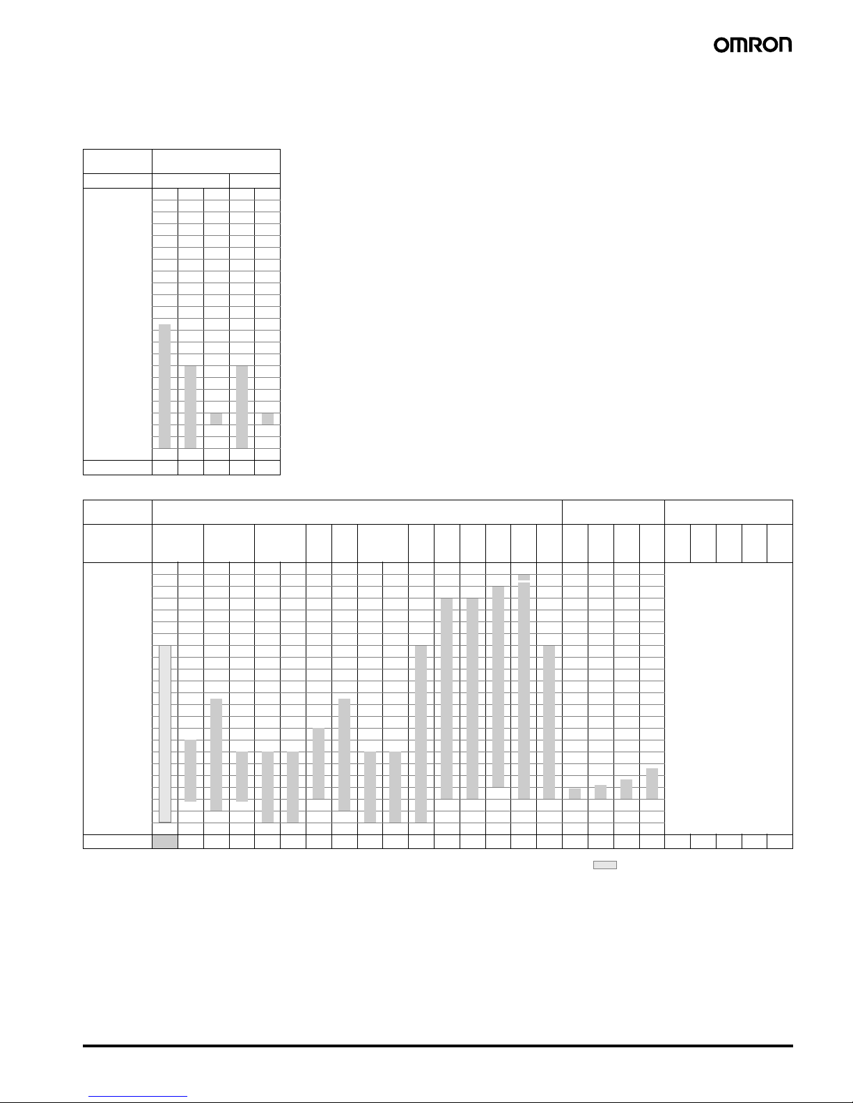
■ Input Ranges
Sensor inputs are fully multi-input. Therefore, platinum resistance thermometer, thermocouple, infrared thermosensor, and analog input can be
selected.
Inputs can be set for each channel using multi-inputs.
Input type Platinum resistance
thermometer
Name Pt100 JPt100
Tem perature
range
(
°C)
2300
1800
1700
1600
1500
1400
1300
1200
1100
1000
900
800
700
600
500
400
300
200
100
0
−100.0
−200.0
850
500.0 500.0
100.0 1 00.0
0.0 0.0
−200 −199.9 −199.9
Setting number
01234
Input type Thermocouple ES1B Infrared
Thermosensor
Analog input
Name K J T E L U N R S B W PL
II
10
to
70
°C
60
to
120
°C
115
to
165
°C
140
to
260
°C
4 to
20
mA
0 to
20
mA
1 to
5 V
0 to
5 V
0 to
10 V
Tem perature
range
(
°C)
2300
1800
1700
1600
1500
1400
1300
1200
1100
1000
900
800
700
600
500
400
300
200
100
0
−100.0
−200.0
2300
Any of the following ranges,
by scaling:
−1999 to 9999
−199.9 to 999.9
−19.99 to 99.99
−1.999 to 9.999
1800
1700 1700
1300 1300 1300
850 850
600
500.0
400.0 400 400.0 400 400.0
260
120 165
90
100
0 00 000000
−20.0 −100 −20.0 −100
−200 −200 −199.9 −200 −199.9 −200
Setting number
5 6 7 8 9 1011121314151617181920212223242526272829
Applicable standards by input type are as follows:
K, J, T, E, N, R, S, B: JIS C1602-1995, IEC584-1
L: Fe-CuNi, DIN 43710-1985
U: Cu-CuNi, DIN 43710-1985
W: W5Re/W26Re, ASTM E988-1990
PL II: According to Platinel II Electromotive Force
Table by Engelhard Cor p.
JPt100: JIS C 1604-1989, JIS C 1606-1989
Pt100: JIS C 1604-1997 IEC 751
Shaded ranges indicate default settings.
Page 6

6 Modular Temperature Controller for Gradient Temperature Control EJ1G
■ Ratings
Note: 1. Auxiliary outputs can be allocated using auxiliary output allocations.
2. Allocated using the digital input allocation function.
■ Characteristics
EJ1G-HFU
Power supply voltage 24 VDC
Operating voltage range 85% to 110% of rated voltage
Power consumption 2 W max. (at maximum load)
Auxiliary outputs
(See note 1.)
Outputs 4
Transistor outputs Max. operating voltage: 30 VDC, Max. load current: 50 mA
Event inputs
(See note 2.)
Inputs 4
Inputs with contacts ON: 1 k
Ω max., OFF: 100 kΩ min.
Inputs without contacts ON: Residual voltage of 1.5 V max., OFF: Leakage current of 0.1 mA max.
Short-circuit current: Approx. 4 mA (per contact)
Programless
connection
Programless downloading
(EJ1G writes data to a PLC)
Number of parameters that can be set: 300
Programless uploading
(EJ1G reads data from a
PLC)
Number of parameters that can be set: 300
Applicable PLCs OMRON: SYSMAC CS/CJ Series, Mitsubishi Electric: MELSEC-Q/QnAS Series
Control method 2-PID control (with autotuning), gradient temperature control (with gradient tuning function)
Other functions 2-point input shift, SP ramp, manual manipulated variable, manipulated variable limiter,
interference overshoot adjustment, heater burnout alarm, RUN/STOP, banks, I/O allocations,
etc.
Ambient temperature range Operating:
−10°C to 55°C
Storage:
−25°C to 65°C (with no icing or condensation)
Ambient humidity range Operating: 25% to 85% (with no condensation)
Insulation resistance 20 M
Ω min. (at 500 VDC)
Dielectric strength 600 VAC, 50/60 Hz for 1 min between current-carrying terminals of different polarity
Vibration resistance
10 to 55 Hz, 20 m/s
2
for 2 hours each in X, Y, and Z directions
Shock resistance
150 m/s
2
max., 3 times each in 6 directions
Weight 160 g
Degree of protection Rear case: IP20, Terminal section: IP00
Memory protection EEPROM (non-volatile memory) (number of writes: 100,000)
Standards Approved standards UL61010C-1, CSA C22.2 No.1010-1
Conformed standards EN61010-1 (IEC61010-1): Pollution level 2, overvoltage category II
EMC Directive Refer to page 3.
Page 7
Modular Temperature Controller for Gradient Temperature Control EJ1G 7
■ Communications Characteristics: Port C
Communications are not possible from port B on the End Unit. A connection is made between ports B when using distributed placement.
Note: 1. The communications method can be switched between RS-485 and RS-232C. Another model must be used for RS-422 communications.
2. For the number of Units that can be connected, refer to “Connection Precautions” on page 9.
3. When performing gradient temperature control, the number of control channels is limited by the group setting. For details, refer to “Gradient Group Settings”
on page 11.
■ Ratings
■ Characteristics
■ Communications
Note: Port A connector communications and port A terminal communications cannot be used at the same time.
Transmission path connection RS-485/RS-422: Multi-point, RS-232C: Point-to-point (See note 1.)
Communications method RS-485/RS-422 (two-wire, half duplex), RS-232C
Synchronization method Start-stop synchronization
Baud rate 9.6, 19.2, 38.4, 57.6, or 115.2 kbps
Transmission code ASCII
Data bit length 7 or 8 bits
Stop bit length 1 or 2 bits
Error detection Vertical parity (none, even, or odd)
Block check character (BCC) with CompoWay/F
Flow control None
Interface RS-485, RS-422, RS-232C (See note 1.)
Retry function None
Communications response wait time 1 to 99 ms (default: 5 ms)
Number of Units that can be connected in
parallel (See notes 2 and 3.)
16 Units (model numbers with TC4: 64 channels, model numbers with TC2: 32 channels)
End Unit/EJ1C-EDU
Power supply voltage 24 VDC
Operating voltage range 85% to 110% of rated voltage
Auxiliary output Outputs 2
Transistor outputs Max. operating voltage: 30 VDC, Max. load current: 50 mA
Ambient temperature range Operating:
−10°C to 55°C
Storage:
−25°C to 65°C (with no icing or condensation)
Ambient humidity range Operating: 25% to 85% (with no condensation)
Insulation resistance 20 M
Ω min. (at 500 VDC)
Dielectric strength 600 VAC, 50/60 Hz for 1 min between current-carrying terminals of different polarity
Vibration resistance
10 to 55 Hz, 20 m/s
2
for 2 hours each in X, Y, and Z directions
Shock resistance
150 m/s
2
max., 3 times each in 6 directions
Weight 70 g
Degree of protection End Unit case: IP20, Terminal section: IP00
Standards Approved standards UL61010C-1, CSA C22.2 No.1010-1
Conformed standards EN61010-1 (IEC61010-1): Pollution level 2, overvoltage category II
EMC Directive Same as for the Basic Unit. Refer to page 3.
Por t A Basic Unit Communications (Refer to “Communications Specifications” on page 4.)
Port A connector (See note.) E58-CIFQ1
Page 8
8 Modular Temperature Controller for Gradient Temperature Control EJ1G
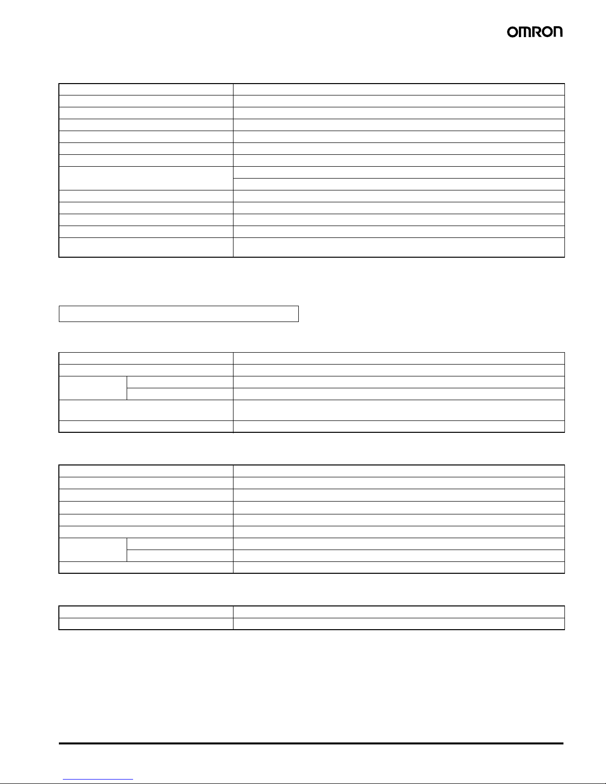
Unit Configuration Example
■ Basic Configuration for Gradient Temperature Control
• Systems can be built with host PLCs using programless communications.
• Distributed placement is possible by using multiple EJ1C-EDU End Units.
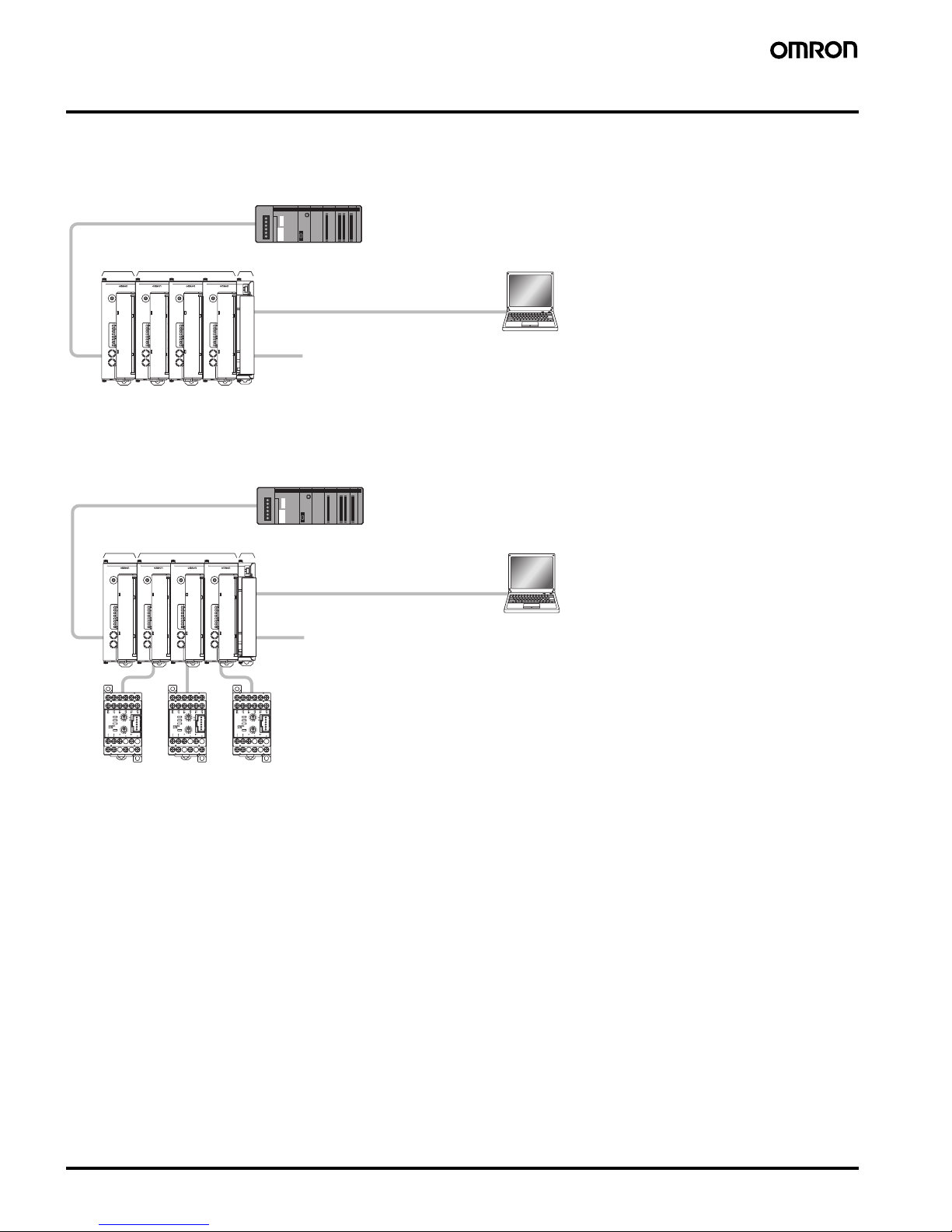
■ Basic Configuration for Connection to G3ZA Multi-channel Power
Controllers
Up to 8 G3ZA Controllers can be connected to each Basic Unit.
COM1
COM2
COM3
PWR
RUN
ERR
ALM
SW1
ON
SW2
21345678
EJ1-TC4
0
1
2
3
4
5
6
7
8
9
A
B
C
D
E
F
COM1
COM2
COM3
PWR
RUN
ERR
ALM
SW1
ON
SW2
21345678
EJ1-TC4
0
1
2
3
4
5
6
7
8
9
A
B
C
D
E
F
COM1
COM2
COM3
PWR
RUN
ERR
ALM
SW1
ON
SW2
21345678
EJ1-TC4
0
1
2
3
4
5
6
7
8
9
A
B
C
D
E
F
COM1
COM2
COM3
PWR
RUN
ERR
ALM
SW1
ON
SW2
21345678
EJ1-HFU
0
1
2
3
4
5
6
7
8
9
A
B
C
D
E
F
GTC
PC
EJ1G-HFU
PLC
EJ1G-TC4
or
EJ1G-TC2 EJ1C-EDU
Por t B
Use port B for configurations with distributed placement.
Port A (connector): USB connection can be made with the
E58-CIFQ1 (sold separately).
CX-Thermo for setting
Por t C
SW2
SW1
ERROR
OCC
SD/RD
READY
SW2
SW1
ERROR
OCC
SD/RD
READY
SW2
SW1
ERROR
OCC
SD/RD
READY
PC
COM1
COM2
COM3
PWR
RUN
ERR
ALM
SW1
ON
SW2
21345678
EJ1-TC4
0
1
2
3
4
5
6
7
8
9
A
B
C
D
E
F
COM1
COM2
COM3
PWR
RUN
ERR
ALM
SW1
ON
SW2
21345678
EJ1-TC4
0
1
2
3
4
5
6
7
8
9
A
B
C
D
E
F
COM1
COM2
COM3
PWR
RUN
ERR
ALM
SW1
ON
SW2
21345678
EJ1-TC4
0
1
2
3
4
5
6
7
8
9
A
B
C
D
E
F
COM1
COM2
COM3
PWR
RUN
ERR
ALM
SW1
ON
SW2
21345678
EJ1-HFU
0
1
2
3
4
5
6
7
8
9
A
B
C
D
E
F
GTC
G3ZA G3ZAG3ZA
EJ1G-HFU
PLC
EJ1G-TC4
or
EJ1G-TC2 EJ1C-EDU
Por t B
Use port B for configurations with distributed placement.
Port A (connector): USB connection can be made with the
E58-CIFQ1 (sold separately).
CX-Thermo for setting
G3ZA
connection port
G3ZA
connection
port
Por t C
G3ZA
connection
port
Page 9

Modular Temperature Controller for Gradient Temperature Control EJ1G 9
■ Connection Precautions
Node Number Setting
Nodes 0 to 31 can be used for HFUs and Basic Units.
Restrictions on the Number of Units
that Can Be Connected
Restrictions for HFUs
• One EJ1G-HFU can manage up to 16 Basic Units (EJ1G-TC4/
TC2).
• Up to 16 Units can be connected side by side including the EJ1GHFU. The End Unit is not included in the 16 Units.
Note: When performing gradient temperature control, the number of
control channels is limited by the group setting. For details,
refer to “Gradient Group Settings” on page 11.
Restrictions When Connecting with the
G3ZA
• Up to 8 G3ZA Multi-channel Power Controllers can be connected to
one Basic Unit (EJ1G-TC4/TC2).
Wiring for Distributed Placement
Note: Wire the dotted line when settings for all EJ1G are being made
from one port A connector.
If the dotted lines are not wired, settings for group A must be
made using the port A connector and settings for group B must
be made using the port A connector.
Restrictions on Unit Placement
Always connect the HFU on the left side of the Basic Unit.
COM1
COM2
COM3
PWR
RUN
ERR
ALM
SW1
ON
SW2
21345678
EJ1-TC4
0
1
2
3
4
5
6
7
8
9
A
B
C
D
E
F
COM1
COM2
COM3
PWR
RUN
ERR
ALM
SW1
ON
SW2
21345678
EJ1-TC4
0
1
2
3
4
5
6
7
8
9
A
B
C
D
E
F
COM1
COM2
COM3
PWR
RUN
ERR
ALM
SW1
ON
SW2
21345678
EJ1-TC4
0
1
2
3
4
5
6
7
8
9
A
B
C
D
E
F
COM1
COM2
COM3
PWR
RUN
ERR
ALM
SW1
ON
SW2
21345678
EJ1-TC4
0
1
2
3
4
5
6
7
8
9
A
B
C
D
E
F
COM1
COM2
COM3
PWR
RUN
ERR
ALM
SW1
ON
SW2
21345678
EJ1-HFU
0
1
2
3
4
5
6
7
8
9
A
B
C
D
E
F
COM1
COM2
COM3
PWR
RUN
ERR
ALM
SW1
ON
SW2
21345678
EJ1-TC4
0
1
2
3
4
5
6
7
8
9
A
B
C
D
E
F
GTC
EJ1G-TC4 or
EJ1G-TC2
One HFU can manage up to 16 Basic Units
(when using the EJ1G-TC4: 4 channels x 16 Units = 64 channels)
EJ1C-EDU
EJ1C-EDU
Por t B
Por t B
EJ1G-HFU
Por t C
EJ1G-TC4
or
EJ1G-TC2
Up to 16 Units can be connected side by side.
Note: End Units are not included in the number
of Units that can be connected.
To the host device
COM1
COM2
COM3
PWR
RUN
ERR
ALM
SW1
ON
SW2
21345678
EJ1-TC4
0
1
2
3
4
5
6
7
8
9
A
B
C
D
E
F
EJ1C-EDU
EJ1G-HFU
SW2
SW1
ERROR
OCC
SD/RD
READY
SW2
SW1
ERROR
OCC
SD/RD
READY
SW2
SW1
ERROR
OCC
SD/RD
READY
SW2
SW1
ERROR
OCC
SD/RD
READY
COM1
COM2
COM3
PWR
RUN
ERR
ALM
SW1
ON
SW2
21345678
EJ1-HFU
0
1
2
3
4
5
6
7
8
9
A
B
C
D
E
F
GTC
Up to 8 G3ZA Power Controllers can be connected to one Basic Unit.
EJ1G-TC4 or EJ1G-TC2
G3ZA
G3ZA connection port
COM1
COM2
COM3
PWR
RUN
ERR
ALM
SW1
ON
SW2
21345678
EJ1-TC4
0
1
2
3
4
5
6
7
8
9
A
B
C
D
E
F
COM1
COM2
COM3
PWR
RUN
ERR
ALM
SW1
ON
SW2
21345678
EJ1-HFU
0
1
2
3
4
5
6
7
8
9
A
B
C
D
E
F
1
2
3
4
5
6
7
8
9
COM1
COM2
COM3
PWR
RUN
ERR
ALM
SW1
ON
SW2
21345678
EJ1-TC4
0
1
2
3
4
5
6
7
8
9
A
B
C
D
E
F
1
2
3
4
5
6
7
8
9
GTC
Group A
Group B
Por t A
Por t B
Por t A
Por t B
24 VDC
RS-485
RS-485
24 VDC
COM1
COM2
COM3
PWR
RUN
ERR
ALM
SW1
ON
SW2
21345678
EJ1-HFU
0
1
2
3
4
5
6
7
8
9
A
B
C
D
E
F
COM1
COM2
COM3
PWR
RUN
ERR
ALM
SW1
ON
SW2
21345678
EJ1-TC4
0
1
2
3
4
5
6
7
8
9
A
B
C
D
E
F
EJ1G-HFUEJ1G-TC4 or
EJ1G-TC2
Page 10

10 Modular Temperature Controller for Gradient Temperature Control EJ1G
■ Insulation Blocks
Each EJ1G Unit is electrically insulated for each function block as shown in the following figures.
Functional insulation is applied between the power supply, input, output, and communications terminal sections.
If reinforced double insulation is required, use power supplies that comply with IEC60664 for reinforced double insulation for the EJ1G's external
power supply and for power supplies connected to the EJ1G.
■ Programless Communications
Communications with PLCs from OMRON (SYSMAC CS/CJ Series) and Mitsubishi Electric (MELSEC-Q/QnAS Series) can be performed without
creating ladder programming.
Using programless communications enables monitoring and changing settings for the EJ1G by simply reading and writing to PLC memory.
The EJ1G automatically performs communications with the PLC, which reduces work hours spent programming for communications from the PLC
to the EJ1G.
Connectable Devices
SYSMAC CS/CJ Series
Note: Use only products manufactured on or after December 20,
1999.
For details, refer to the CS/CJ Series, Serial Communications
Boards/Units Operation Manual (Cat. No. W336).
MELSEC-Q/QnAS Series
Note: 1. Refer to the Mitsubishi Electric manual for the MELSEC.
2. Direct connections to the EJ1G are possible with RS-232C
and RS-422.
3. Even when using RS-422, multiple Units cannot be
connected to the PLC.
Tests have verified that the EJ1G can be connected to the
Mitsubishi Electric models listed above, but design changes
and other factors may still prevent connection. Confirm
proper connect prior to building the system.
Powe r
supply
Transistor outputs 1 to 4
Communications (Port B, port C)
Functional isolation
Powe r
supply
Transistor outputs 1 to 2
Communications (Port A, port B)
Functional isolation
Input 1
Powe r
supply
Input 2
Communications (Port A, port B, G3ZA)
Transistor outputs 3 and 4
Voltage outputs 1 and 2
Functional isolation
EJ1G-HFU
Input 1
Powe r
supply
Input 2
Input 4
Voltage outputs 1 to 4
Communications (Port A, Port B, G3ZA)
Input 3
Functional isolation
EJ1G-TC2 EJ1G-TC4
EJ1C-EDU
PV
PLC
The read monitor value is
written to the PLC memory.
Manipulated variable
Status
SP
Monitor
Setting
Alarm value 1
Alarm value 2
EJ1G-HFU
The EJ1G-HFU automatically
performs communications
with the PLC.
The EJ1G-HFU reads the value
written to the PLC memory.
Monitoring can be
performed for the
EJ1G and the
settings can be
changed by simply
reading and writing
to memory.
PV
Manipulated variable
Status
SP
Alarm value 1
Alarm value 2
Name Model No. Communications ports
Port 1 Port 2
Serial
Communications
Unit
CJ1W-SCU21-V1 RS-232C RS-232C
CJ1W-SCU41-V1 RS-422A/
485
RS-232C
CS1W-SCU21-V1
(See note.)
RS-232C RS-232C
Serial
Communications
Board
CS1W-SCB21-V1
(See note.)
RS-232C RS-232C
CS1W-SCB41-V1
(See note.)
RS-232C RS-422A/
485
CPU Unit CJ1 Series --- RS-232C
CS1 Series --- RS-232C
Name Model No. Communications
ports
Channel 1 Channel 2
Q-compatible
Serial
Communications
Unit
QJ71C24N
QJ71C24
RS-232C RS-422/
485
QJ71C24N-R2
QJ71C24-R2
RS-232C RS-232C
QJ71C24N-R4 RS-422/
485
RS-422/
485
QnAScompatible Serial
Communications
Unit
A1SJ71QC24N RS-232C RS-422/
485
A1SJ71QC24N-R2 RS-232C RS-232C
Page 11

Modular Temperature Controller for Gradient Temperature Control EJ1G 11
Gradient Temperature Control Settings
■ Gradient Group Settings
The gradient group settings are made on the HFU, as described
below.
Example: In this example, 3-channel gradient temperature control is
performed by heater blocks in three locations.
• Gradient temperature control is divided into three groups.
• One channel of 2-PID control is used for each heater block (making
a total of three channels).
• All channels are set to detect heater burnouts.
For the group settings, the heaters are first divided into groups and it
is decided whether each group will use gradient temperature control
or 2-PID control. In this example, there are three groups of gradient
temperature control for three channels, and one group of 2-PID
control for three channels. The groups are divided as shown below.
Group Division into Gradient Temperature Control and 2-PID
Control
The group settings are made with the following parameters.
Note: When the group settings are changed after temperature control
has been performed, the control-related parameters are not
initialized. To redo the group settings after control has been
performed, be sure to initialize the setting parameters before
changing the group settings.
The group settings for this example are as given here.
The HFU handles all of the operations for gradient temperature
control and 2-PID control. The maximum number of enabled
channels that can be controlled is selected at the HFU from 4, 8, 16,
or 32 channels, and that number of channels is allocated for the
number of groups used.
In this example, the maximum number of enabled channels is three,
so the HFU allocates groups in units of four channels each. The HFU
recognizes the following channels for the Basic Unit.
Allocation of Channels Inside the HFU
Parameter Description
Number of enabled
groups
Sets the total number of groups, consisting of
those performing gradient temperature control
and those performing 2-PID control.
Initial Communications
Unit No.
Sets the communications unit number for the
group's initial channel.
Initial channel Sets the initial channel for the initial
communications unit number.
Number of enabled
channels
Sets the number of channels performing
gradient temperature control or 2-PID control.
Control type Sets whether the group will perform gradient
temperature control or 2-PID control.
0
HFU
HFU: Advanced Unit
TC2: 2-channel Basic Uni
t
EDU: End Unit
1
TC22TC23TC24TC25TC26TC2 EDU
Lower heater (gradient temperature control performed for three heaters)
Heater block 1 Heater block 2 Heater block 3
Upper heater (2-PID control)
0
HFU1CH12CH1
Group 1 (Gradient)
3
CH14CH15CH16CH1
CH2 CH2 CH2 CH2 CH2 CH2
TC2 TC2 TC2 TC2 TC2 TC2
EDU
Group 2 (Gradient)
Group 3 (Gradient)
Group 4 (2-PID)
Varia ble
type
Address Parameter Setting value
F1 (B1) 0000 Number of enabled groups 4
0100 Group 1Initial Communications Unit
No.
1
0101 Initial channel 0
0102 Number of enabled
channels
3
0103 Control type 0: Gradient
temperature
control
0200 Group 2Initial Communications Unit
No.
2
0201 Initial channel 1
0202 Number of enabled
channels
3
0203 Control type 0: Gradient
temperature
control
0300 Group 3Initial Communications Unit
No.
4
0301 Initial channel 0
0302 Number of enabled
channels
3
0303 Control type 0: Gradient
temperature
control
0400 Group 4Initial Communications Unit
No.
5
0401 Initial channel 1
0402 Number of enabled
channels
3
0403 Control type 1: 2-PID
control
0
HFU
12
Group 1 (Gradient)
3456
TC2 TC2 TC2 TC2 TC2 TC2
EDU
Group 2 (Gradient)
Group 3 (Gradient)
Group 4 (2-PID)
CH1 CH3 CH6 CH9
CH11 CH14
CH2 CH5 CH7
CH10 CH13 CH15
Page 12

12 Modular Temperature Controller for Gradient Temperature Control EJ1G
The HFU can control up to 64 channels, but when the maximum
number of enabled channels is a number other than 4, 8, 16, or 32
channels, non-usable channels result as shown in this example. This
limits the number of controllable channels and connectable Units.
The example used here results in the following group division and heater connection.
Note: The connections for heater blocks 2 and 3 are omitted above.
■ Gradient Temperature Control
Operations
The HFU handles all of the operations for gradient temperature
control.
The temperature input is received by the Basic Units (TC2 or TC4),
calculated by the HFU, and then output from the Basic Units (TC2 or
TC4) as manipulated variables.
General Flow of Gradient Operations
■ Arrangement of Gradient
Temperature Control Sensors
Arrange the sensors sequentially to maximize the control
performance within the gradient temperature control groups.
Examples for linear arrangement of
heaters
Examples for planar arrangement of
heaters
HFU channels Groups
11
2
3
4 Not usable
52
6
7
8 Not usable
93
10
11
12 Not usable
13 4
14
15
16 Not usable
0
HFU
1
CH12CH33CH64CH95CH116CH14
CH2 CH5 CH7
CH10 CH13 CH15
TC2 TC2 TC2 TC2 TC2 TC2
EDU
CH15
Heater block 3
CH9 CH10 CH11
CH14
Heater block 2
CH13
Heater block 1
CH1 CH2 CH3 CH5 CH6 CH7
HFU
TC2 TC2 TC2 TC2
Sensor input
Output manipulated variables
TC2 TC2 EDU
Gradient
calculation
1CH 2CH 3CH 4CH 5CH 1CH 3CH 5CH 4CH 2CH
Good example Bad example
3CH 5CH 2CH
7CH 9CH 8CH
1CH 4CH 6CH
7CH 8CH 9CH
6CH 1CH 2CH
5CH 4CH 3CH
Good example Bad example
Page 13

Modular Temperature Controller for Gradient Temperature Control EJ1G 13
Connection
■ External Connection
• Functional insulation is applied between the power supply and the I/O sections. If reinforced insulation is required, connect the input
and output terminals to devices without any exposed current-carrying parts or to devices with reinforced insulation suitable for the
maximum operating voltage of the power supply and I/O sections.
• To comply with the standards for noise terminal voltage for class A in EN 61326, install a noise filter (Densei Lamda MXB-1206-33 or
the equivalent) to the DC power line as close as possible to the Temperature Controller.
• Use a SELV power supply. An SELV circuit is one separated from the power supply with double insulation or reinforced insulation,
that does exceed an output voltage of 30 V r.m.s. and 42.4 V peak or 60 VDC max. The OMROM S8VS Series is recommended for the
power supply.
EJ1G-TC4 EJ1G-TC2
EJ1G-HFU EJ1C-EDU
Note: 1. To connect to the G3ZA, connect a G3ZA Connecting Cable (EJ1C-CBLA050, sold separately) to the G3ZA connection port (CN1) on
the EJ1.
2. To connect to a computer using the port A connector, use an E58-CIFQ1 USB-Serial Conversion Cable (sold separately). The
Temperature Controller can be connected to a computer using USB.
3. Terminals A10 and B10 are not used on models with screw-less clamp terminals. Do not connect anything to these terminals.
12 VDC
12 VDC
OUT4
OUT3
12 VDC
12 VDC
OUT2
OUT1
B1
B2
B3
B4
B5
B6
B7
B8
B9
A1
A2
A3
A4
A5
A6
A7
A8
A9
CH4
CN1
G3ZA connection port
Analog
input
Pt Thermo-
couple
A
B
B
mA
V
CH3
A
B
B
mA
V
CH2
A
B
B
mA
V
CH1
A
B
B
mA
V
Circuit 1
Circuit 1
OUT4
OUT3
B1
B2
B3
B4
B5
B6
DC12V
DC12V
B7
B8
B9
CN1
OUT2
OUT1
A1
A2
A3
A4
A5
A6
A7
A8
A9
CT2
CT1
Circuit 1
Circuit 2
G3ZA connection por
t
CH2
A
B
B
mA
V
CH1
A
B
B
mA
V
Analog
input
Pt Thermo-
couple
DO NOT USE
DO NOT USE
DO NOT USE
RS-485 for port C and RS-232C
can be switched.
Another model must be used for
RS-422 communications.
RS-485
DO NOT
USE
SUB2
SUB1
RS-232C
SD
RD
SG
B1
B2
B3
B4
B5
B6
SUB4
SUB3
B7
B8
B9
B
A
A1
A2
A3
A4
A5
A6
A7
A8
A9
Circuit 2
Por t C
Por t C
Circuit 2
DO NOT
USE
DO NOT
USE
RS-422
RS-422
SDB
SDA
RDB
RDA
EV2
EV1
EV4
EV3
Input power suppl
y
Port A connector
Por t B
Por t A
These two ports
cannot be used
at the same time.
Used for distributed
placement.
B
A
B
A
24 VDC
SUB2
SUB1
1
2
3
4
5
6
7
8
9
RS-485
RS-485
Circuit 2
Page 14

14 Modular Temperature Controller for Gradient Temperature Control EJ1G
■ Internal Wiring
Circuit 1
Circuit 2
Circuit 3
Nomenclature and Specification Settings
■ Nomenclature
Operation Indicators
EJ1G-TC2/TC4
EJ1G-HFU
Note: Some time is required for the indicators to light after the power
is turned ON.
L
+V
GND
B1/B2
EJ1G
-TC4
B3
L
B1/B2
EJ1GTC2
B3
A1/A2
EJ1GTC4
A3
L
A1/A2
EJ1G
-TC2
A3
B1/B2
EJ1G
-HFU
B3
B4/B5
EJ1G
-HFU
B6
3/4
EJ1C
-EDU
5
+V
GND
A6
A4/A5
EJ1G
-TC2
A3
A1/A2
EJ1G
-HFU
A6
A4/A5
EJ1G
-HFU
COM1
COM2
COM3
EJ1G-
PWR
RUN
ERR
ALM
SW1
ON
SW2
21345678
0
1
2
3
4
5
6
7
8
9
A
B
C
D
E
F
Operation
Indicators
COM1
COM2
COM3
Operation
Indicators
PWR
RUN
ERR
ALM
SW1
SW2
Operation
Indicators
Meaning
PWR (green) Lights when the power is ON.
RUN (There is no "RUN" indication printed on the Basic
Unit.)
ERR (red) Flashes or lights when an error occurs.
ALM (red) Lights when an alarm is activated.
COM 1 (orange) Flashes during communications via port A on the
End Unit.
COM 2 (orange) Flashes when the EJ1G is in operation.
COM 3 (orange) Flashes during communications with the G3ZA.
Operation
Indicators
Meaning
PWR (green) Lights when the power is ON. (See note.)
RUN (green) Lights during operation.
ERR (red) Flashes or lights when an error occurs.
ALM (red) Lights when an alarm is activated.
COM 1 (orange) Flashes during communications via port A on the
End Unit.
COM 2 (orange) Flashes when the EJ1G system is in operation.
COM 3 (orange) Flashes during communications via port C.
Page 15

Modular Temperature Controller for Gradient Temperature Control EJ1G 15
■ Specification Settings
Switch Operation
• Check that the EJ1G is turned OFF before operating the switches.
Settings are read only when power is turned ON.
• Set the switches with a small flat-blade screwdriver. Do not set the
switches midway between settings.
• SW1 is set to 1 and SW2 pins are all set to OFF in the default
settings.
Setting the Unit Number
SW1 and SW2 are used together to set the unit number to between
00 and 31. The factory setting is unit number 01.
SW2 Settings
EJ1G-TC2/TC4
EJ1G-HFU
Dimensions
Note: All units are in millimeters unless otherwise indicated.
■ Temperature Controller
SW2 SW1
1 0123456789ABCDEF
OFF 00 01 02 03 04 05 06 07 08 09 10 11 12 13 14 15
ON 16 17 18 19 20 21 22 23 24 25 26 27 28 29 30 31
SW1 SW2
SW2 Meaning
2 to 6 Not used (OFF)
7 ON: G3ZA in operation
8 Use when Units are distributed.
(Refer to the operation manual for details.)
SW2 Meaning
2 to 7 Not used (OFF)
8
• EJ1G-HFU@-NFLK
OFF: RS-485 is selected.
ON: RS-232C is selected.
• EJ1G-HFU@-NFL2
Not used (OFF).
0
1
2
3
4
5
6
7
8
9
A
B
C
D
E
F
COM1
COM2
COM3
PWR
RUN
ERR
ALM
SW1
ON
SW2
21345678
0
1
2
3
4
5
6
7
8
9
A
B
C
D
E
F
COM1
COM2
COM3
EJ1G-EJ1G-
PWR
RUN
ERR
ALM
SW1
ON
SW2
21345678
(109 for Screws Terminals)
(104.85 for Screw-less Clamp Terminals)
27.0
35.4
27.6
9095.4
31
31
(Screw-less
Clamp Terminals)
(Screws Terminals)
Basic Uni
ts
EJ1G-TC
HFUs
EJ1G-HFU
76.2
60
15.7
9095.4
27.0
35.4
27.6
End Units
EJ1C-EDU
Page 16

16 Modular Temperature Controller for Gradient Temperature Control EJ1G
■ Options
Current Transformer (Sold Separately)
40@
30
12 dia.
9
2.36 dia.
15
30
Two, M3 (depth: 4)
E54-CT3
Plug
Armature
Lead
30
21
15
5.8 dia.
25
3
40
10.5
2.8
7.5
10
Two, 3.5 dia.
E54-CT1
Connection Example
Approx. 3 dia.
18
(22)
Approx. 6 dia.
E54-CT3 Accessory
• Armature
• Plug
4.5
15 25 25
10 10
1000 (500)
(See note.)
25 25 15 (5)
(See note.)
35
±0.3
7.3±0.15
27±0.15
1
Rail Mounting Equipment (Order Separately)
DIN Rail
PFP-100N
PFP-50N
Note: The figures in parentheses
are dimensions for the
PFP-50N.
50
11.5
10
M4 × 8
panhead
screw
M4 spring washer 4.8
1.3
1.8
1
10
6.2
1.8
35.5 35.
3
End Plate
PFP-M
Note: Two screws are included with the EJ1C-EDU for the End Plate.
Always attach End Plates to both sides.
Page 17

Modular Temperature Controller for Gradient Temperature Control EJ1G 17
I/O Devices
■ Examples of EJ1G-series Temperature Controllers Connected with
Temperature Sensors and SSRs
SW2
SW1
ERROR
OCC
SD/RD
READY
G3ZA
SSR SSR
Eight Units max.*
SSR SSR
COM1
COM2
COM3
PWR
RUN
ERR
ALM
SW1
ON
SW2
21345678
EJ1-TC2
0
1
2
3
4
5
6
7
8
9
A
B
C
D
E
F
COM1
COM2
COM3
PWR
RUN
ERR
ALM
SW1
ON
SW2
21345678
EJ1-TC2
0
1
2
3
4
5
6
7
8
9
A
B
C
D
E
F
COM1
COM2
COM3
PWR
RUN
ERR
ALM
SW1
ON
SW2
21345678
EJ1-TC2
0
1
2
3
4
5
6
7
8
9
A
B
C
D
E
F
COM1
COM2
COM3
PWR
RUN
ERR
ALM
SW1
ON
SW2
21345678
EJ1-TC2
0
1
2
3
4
5
6
7
8
9
A
B
C
D
E
F
EJ1G
G3ZA
Multi-channel Power Controller
EJ1G-TC2
EJ1G-TC4
Temperature controller
Voltage output
terminal
(for driving SSR)
SSR
INPUT LOAD
Load
Heater
Load
power
supply
G3PC (SSR with failure detection)
Ultra-compact and slim
model combined with a
heat radiator
Rated input voltage:
12 to 24 VDC
3
3
2
2
Converters, Digital Panel Meters, Flow Meters,
Infrared Thermosensors, Displacement Sensors,
etc.
240 VAC, 20 A
240 VAC, 10 A, 20 A, 40 A, or 60 A
400 VAC, 20 A, 30 A, or 50 A
240 VAC, 5 A, 10 A, 20 A, 40 A, 75 A, or 90 A
480 VAC, 10 A, 20 A, 40 A, 75 A, or 90 A
A
G
H
T
U
OMRON
AG
H
T
UR
W
N
B
VC
D
SIO
LH
G
F
AG
H
T
U
RW
N
B
VC
D
SIO
LH
G
F
A
G
H
TU
R
W
N
BV
C
D
S
IOL
H
G
F
A
G
H
T
U
R
W
N
B
V
C
A
G
H
T
U
R
W
N
B
V
C
A
G
H
TU
A
A
A
A
O
M
R
O
N
A
G
H
T
U
R
W
N
B
V
C
A
G
H
T
U
R
A
G
A
G
A
G
H
T
A
G
H
T
U
R
W
N
B
V
C
D
S
A
G
H
T
U
R
W
N
B
V
C
D
S
A
G
H
T
U
R
W
N
B
V
C
D
S
A
GH
TU
RW
NBV
CDS
A
G
H
T
U
R
W
AGHTURW
A
G
H
T
U
R
W
A
G
H
T
AG
H
TURW
NBV
CDS
A
G
H
T
A
G
H
T
A
G
H
T
A
G
H
T
A
G
H
T
A
G
H
T
A
G
H
T
A
G
H
T
A
G
H
T
A
G
H
T
A
G
H
T
A
G
H
T
U
R
W
N
B
V
C
D
S
G3PB (Single Phase)
Ultra-compact and slim
model combined with a
heat radiator
Rated input voltage:
12 to 24 VDC
240 VAC, 15 A, 25 A, 35 A, or 45 A
480 VAC, 15 A, 25 A, 35 A, or 45 A
G3PB (Three Phase)
Three-phase batch
control combined with
heat radiator
Rated input voltage:
12 to 24 VDC
240 or 480 VAC, 15 A, 25 A, 35 A, or 45 A
G3PA
Ultra-compact and slim
model combined with a
heat radiator
Rated input voltage:
5 to 24 VDC
Analog quantities, such as temperature,
flow rate, and concentration
ES1B
Infrared Thermosensor
E52 Thermocouple/Platinum
Resistance Thermometer
G3NA
Standard model
with screw terminals
Rated input voltage:
5 to 24 VDC
G3NE
Rated input voltage:
12 VDC
240 VAC, 5 A, 10 A, or 20 A
3*
*Four 480-V models
*The G3ZA is available with 4 or 8 control points.
4
G3NH
For high-power
heater control
Rated input voltage:
5 to 24 VDC
440 VAC, 75 A or 150 A
Input device/sensor
Can be directly
connected.
1
Special Cable
Two-channel SSR outputs can be
connected to models with TC2.
The number of SSRs that can be
connected for each channel is listed
on the right.
Four-channel SSR outputs can be
connected to models with TC4.
The number of SSRs that can be
connected for each channel is listed
on the right.
ES2-HB Humidity Sensor
ES2-THB Temperature/Humidity Sensor
Number of SSRs That Can
be Connected in Parallel
Compact low-cost
models with quick-
connect terminals
• Concept behind the Number of SSRs That Can Be
Connected in Parallel
(A): The maximum load current for the voltage output
(to drive SSRs) for the Temperature Controller is
21 mA.
(B): The input impedance for SSRs is 7 mA (G3NA).
In this case, the number of SSRs that can be
connected in parallel is (A) ÷ (B), therefore 3.
The maximum load current in the connection example
is 21 mA.
Page 18

18 Modular Temperature Controller for Gradient Temperature Control EJ1G
Safety Precautions
!CAUTION
■ Precautions for Safe Use
Observe the following points to ensure safe operation.
1. The product is designed for indoor use only. Do not use the
product outdoors or in any of the following locations.
• Places directly subject to heat radiated from heating equipment
• Places subject to splashing liquid or oil atmosphere
• Places subject to direct sunlight
• Places subject to dust or corrosive gas (in particular, sulfide gas
or ammonia gas)
• Places subject to intense temperature change
• Places subject to icing or condensation
• Places subject to vibration or strong shocks
2. Use and store the product within the rated temperature and
humidity ranges. Provide forced-cooling if required.
3. To allow heat to escape, do not block the area around the product.
Do not block the ventilation holes on the product.
4. Be sure to wire properly with correct polarity of terminals.
5. Use specified size (M3, width 5.8 mm or less) crimped terminals
for wiring. To connect bare wires to the terminal block, use copper
braided or solid wires with a gage of AWG22 to AWG14 (equal to
cross-sectional area of 0.326 to 2.081 mm
2
) for power supply
lines and a gage of AWG28 to AWG16 (equal to cross-sectional
area of 0.081 to 1.309 mm
2
). (The stripping length is 6 to 8 mm.)
Up to two wires of same size and type, or two crimped terminals
can be inserted into a single terminal.
6. Do not wire terminals that do not have an identified use.
7. Allow as much space as possible between the product and
devices that generate a powerful high-frequency or surge.
Separate the high-voltage or large-current power lines from other
lines, and avoid parallel or common wiring with the power lines
when you are wiring to the terminals.
8. Use the product within the rated load and power supply.
9. Make sure that the rated voltage is attained within two seconds of
turning ON the power.
10.Make sure that the product has 30 minutes or more to warm up
after turning ON the power before starting actual control
operations to ensure the correct temperature display.
11.The switch or circuit breaker must be within easy reach of the
operator, and must be marked as a disconnecting means for this
unit.
12.Do not use paint thinner or similar chemical to clean with. Use
standard grade alcohol.
13.Design the system (e.g., the control panel) allowing leeway for the
delay required before product outputs are valid after turning ON
power to the product.
14.Never touch the electronic components, connectors, or patterns
on product boards with your bare hands. Always hold the product
by the case. Inappropriately handling the product may
occasionally damage internal components due to static electricity.
15.Use a switch, relay, or other device with contacts to turn OFF the
power supply quickly. Gradually lowering the voltage of the power
supply may result in incorrect outputs or memory errors.
16.Do not touch the electronic components with your hands or
subject them to shock when removing the terminal block.
17.Connect only the specified number of products in only a specified
configuration.
18.Mount the product to a DIN Rail mounted vertically to the ground.
19.Always turn OFF the power supply before wiring the product,
replacing the product, or changing the product configuration.
20.Attach the enclosed cover seal to the connector opening on the
left end product during installation.
21.Do not use port B on the end product when using port C on
HFUs.
22.Install the product only after reading the manual provided with the
End Unit.
Do not touch the terminals while power is being supplied.
Doing so may occasionally result in minor injury due to
electric shock.
Use a power supply that complies with the reinforced
insulation specified in IEC 60664 for the EJ1G external
power supply or the power supply connected to the EJ1G.
If non-compliant power supplies are used, electric shock
may occasionally result in minor injury.
Do not allow pieces of metal, wire clippings, or fine
metallic shavings or filings from installation to enter the
product. Doing so may occasionally result in electric
shock, fire, or malfunction.
Do not use the product where subject to flammable or
explosive gas. Otherwise, minor injury from explosion
may occasionally occur.
Never disassemble, modify, or repair the product or touch
any of the internal parts. Minor electric shock, fire, or
malfunction may occasionally occur.
Tighten the terminal screws to between 0.40 and
0.56 N·m. Loose screws may occasionally result in fire.
Set the parameters of the product so that they are
suitable for the system being controlled. If they are not
suitable, unexpected operation may occasionally result in
property damage or accidents.
A malfunction in the product may occasionally make
control operations impossible or prevent alarm outputs,
resulting in property damage. To maintain safety in the
event of malfunction of the product, take appropriate
safety measures, such as installing a monitoring device
on a separate line.
Gradient temperature control controls the average
temperature for more than one channel. If a heater
burnout occurs during gradient temperature control and
the temperature of that channel decreases, physical
damage may occasionally occur because the
temperature of the other channels will increase. When
using gradient temperature control, implement suitable
safety measures for the entire system using heater
burnout alarms or temperature information for individual
channels.
Page 19

Modular Temperature Controller for Gradient Temperature Control EJ1G 19
■ Precautions for Correct Use
Service Life
1. Use the product within the following temperature and humidity
ranges:
Temperature:
−10°C to 55°C (with no condensation or icing)
Humidity: 25% to 85%
When the Temperature Controller is incorporated in a control
panel, make sure that the controller's ambient temperature and
not the panel's ambient temperature does not exceed 55
°C.
2. The service life of electronic devices like Temperature Controllers
is determined not only by the number of times the relay is
switched but also by the service life of internal electronic
components. Component service life is affected by the ambient
temperature: the higher the temperature, the shorter the service
life and the lower the temperature, the longer the service life.
Therefore, the service life can be extended by lowering the
temperature of the Temperature Controller.
3. Mounting two or more Temperature Controllers side by side, or
mounting Temperature Controllers above each other may cause
heat to build up inside the Temperature Controllers, which will
shorten their service life. If the Temperature Controllers are
mounted above each other or side by side, use forced cooling by
fans or other means of air ventilation to cool down the
Temperature Controllers.
However, be sure not to cool only the terminals. Doing so will
result in measurement errors.
Ensuring Measurement Accuracy
1. When extending or connecting the thermocouple lead wire, be
sure to use compensating wires that match the thermocouple
types.
2. When extending or connecting the lead wire of the platinum
resistance thermometer, be sure to use wires that have low
resistance and keep the resistance of the three lead wires the
same.
3. Mount the Temperature Controller so that it is horizontally level.
4. If the measurement accuracy is low, check to see if input shift has
been set correctly.
Precautions for Operation
1. A certain amount of time is required for the outputs to turn ON
from the time the power supply is turned ON. Due consideration
must be given to this time when incorporating Temperature
Controllers in a sequence circuit.
2. It takes 30 minutes from the time the product is turned ON until
the correct temperature is indicated. Always turn ON the power
supply at least 30 minutes before starting temperature control.
3. Avoid using the Temperature Controller near a radio, television
set, or other wireless device. Its use would result in reception
disturbance.
Installation
Connecting Units
1. Align the connectors and connect the Units to each other.
Connect an End Unit to the Unit on the right end. (Up to 16 Units
can be connected side by side.)
Note: 1. Do not connect an End Unit directly to an HFU.
2. Always connect an End Unit to the right side of a Basic Unit.
2. Slide the yellow sliders on the top and bottom of the Units until
they click into place.
3. Attach the cover seal to the connector on the Unit on the left end
of the EJ1G.
Removing the Terminal Block
1. Press down the terminal block lever.
2. Pull out the terminal block.
Slider
Lock
Cover Seal
Lower the lever.
Pull out.
Page 20

20 Modular Temperature Controller for Gradient Temperature Control EJ1G
Mounting to the DIN Rail
Mounting
Catch the hook located on the top of the Unit onto the DIN Rail and
press the Unit until the Unit locks into place.
Dismounting
Pull down on the hook with a flat-blade screwdriver and lift up on the
Unit.
Mount one End Plate to each side of the EJ1C-EDU (PFP-M End
Plates are included with the End Unit).
Install the DIN Rail vertically to the ground.
Applicable DIN Rail (sold separately): PFP-100N (100 cm),
PFP-50N (50 cm)
Wiring Procedure for Screw-less Clamp
Terminals
There are two holes for each terminal. The hole on the right is the
operating hole; the hole on the left is the wire hole. Insert a flat-blade
screwdriver with a width of 2.5 mm into the operating hold and then
insert the wiring into the wire hole. The wire will be clamped when
the screwdriver is removed.
Use crimp terminals for wiring that match the cross-sectional area of
the wiring material.
We recommend the following crimp terminals:
Weidmuller H-sleeve series
Connecting to the G3ZA (EJ1G-TC)
Refer to the “G3ZA Instruction Manual” for wiring methods.
(1) Lower the hooks.
(3) Press in
on the
Unit.
(2) Catch the upper hook
onto the DIN Rail.
(4) Make sure the Unit
is locked into
p
lace.
Flat-blade Screwdriver
PFP-M
Correct
Incorrect
Vertically Horizontally
B1
B2
B3
B4
B5
B6
B7
B8
B9
B10
A1
A2
A3
A4
A5
A6
A7
A8
A9
A10
SW2
SW1
ERROR
OCC
SD/RD
READY
CN1
Connect the G3ZA
Connecting Cable to
the CN1 connector on
the bottom of the TC
Unit.
G3ZA
CN1
EJ1C-CBLA050 (Order separately)
(cable length: 5m)
Connect the black line with a
white stripe to terminal 7 on the
G3ZA and the black line with no
stripe to terminal 8.
Refer to the following manual for precautionary information and other information necessary to use the EJ1G:
EJ1G Modular Temperature Controller Operation Manual (Cat. No. H143)
Page 21

Modular Temperature Controller for Gradient Temperature Control EJ1G 21
Page 22

22 Modular Temperature Controller for Gradient Temperature Control EJ1G
Page 23

Modular Temperature Controller for Gradient Temperature Control EJ1G 23
Page 24

In the interest of product improvement, specifications are subject to change without notice.
ALL DIMENSIONS SHOWN ARE IN MILLIMETERS.
To convert millimeters into inches, multiply by 0.03937. To convert grams into ounces, multiply by 0.03527.
Cat. No. H145-E1-01
OMRON Corporation
Industrial Automation Company
Control Devices Division H.Q.
Analog Controller Division
Shiokoji Horikawa, Shimogyo-ku,
Kyoto, 600-8530 Japan
Tel: (81)75-344-7080/Fax: (81)75-344-7189
Printed in Japan
0806-1M (0806) (C)
Warranty and Application Considerations
Read and Understand This Catalog
Please read and understand this catalog before purchasing the products. Please consult your OMRON representative if you
have any questions or comments.
Warranty and Limitations of Liability
WARRANTY
OMRON's exclusive warranty is that the products are free from defects in materials and workmanship for a period of one year (or
other period if specified) from date of sale by OMRON.
OMRON MAKES NO WARRANTY OR REPRESENTATION, EXPRESS OR IMPLIED, REGARDING NON-INFRINGEMENT,
MERCHANTABILITY, OR FITNESS FOR PARTICULAR PURPOSE OF THE PRODUCTS. ANY BUYER OR USER
ACKNOWLEDGES THAT THE BUYER OR USER ALONE HAS DETERMINED THAT THE PRODUCTS WILL SUITABLY MEET
THE REQUIREMENTS OF THEIR INTENDED USE. OMRON DISCLAIMS ALL OTHER WARRANTIES, EXPRESS OR
IMPLIED.
LIMITATIONS OF LIABILITY
OMRON SHALL NOT BE RESPONSIBLE FOR SPECIAL, INDIRECT, OR CONSEQUENTIAL DAMAGES, LOSS OF PROFITS,
OR COMMERCIAL LOSS IN ANY WAY CONNECTED WITH THE PRODUCTS, WHETHER SUCH CLAIM IS BASED ON
CONTRACT, WARRANTY, NEGLIGENCE, OR STRICT LIABILITY.
In no event shall the responsibility of OMRON for any act exceed the individual price of the product on which liability is asserted.
IN NO EVENT SHALL OMRON BE RESPONSIBLE FOR WARRANTY, REPAIR, OR OTHER CLAIMS REGARDING THE
PRODUCTS UNLESS OMRON'S ANALYSIS CONFIRMS THAT THE PRODUCTS WERE PROPERLY HANDLED, STORED,
INSTALLED, AND MAINTAINED AND NOT SUBJECT TO CONTAMINATION, ABUSE, MISUSE, OR INAPPROPRIATE
MODIFICATION OR REPAIR.
Application Considerations
SUITABILITY FOR USE
OMRON shall not be responsible for conformity with any standards, codes, or regulations that apply to the combination of
products in the customer's application or use of the products.
Take all necessary steps to determine the suitability of the product for the systems, machines, and equipment with which it will
be used.
Know and observe all prohibitions of use applicable to this product.
NEVER USE THE PRODUCTS FOR AN APPLICATION INVOLVING SERIOUS RISK TO LIFE OR PROPERTY WITHOUT
ENSURING THAT THE SYSTEM AS A WHOLE HAS BEEN DESIGNED TO ADDRESS THE RISKS, AND THAT THE OMRON
PRODUCTS ARE PROPERLY RATED AND INSTALLED FOR THE INTENDED USE WITHIN THE OVERALL EQUIPMENT OR
SYSTEM.
Disclaimers
PERFORMANCE DATA
Performance data given in this catalog is provided as a guide for the user in determining suitability and does not constitute a
warranty. It may represent the result of OMRON's test conditions, and the users must correlate it to actual application
requirements. Actual performance is subject to the OMRON Warranty and Limitations of Liability.
CHANGE IN SPECIFICATIONS
Product specifications and accessories may be changed at any time based on improvements and other reasons. Consult with
your OMRON representative at any time to confirm actual specifications of purchased product.
DIMENSIONS AND WEIGHTS
Dimensions and weights are nominal and are not to be used for manufacturing purposes, even when tolerances are shown.
 Loading...