

Page 1

USER’S MANUAL
Modular Temperature Controllers
for Gradient Temperature Control
EJ1G
Cat. No. H143-E1-01
Page 2

EJ1G Modular Temperature Controllers for Gradient Temperature Control
User’s Manual
Produced October 2006
Page 3

iv
Page 4

Preface
r
f
This manual descr ibes the EJ1G Modular Temperature Controllers for Gradient Temperature Control,
including information on functions, performances, and application methods.
Observe the following precautions when us in g an EJ 1G Mod ular Temperature Controllers for Gradient
Temperature Control.
Visual Aids
The following headings appear in the le ft column of the manual to help you locate different types of
information.
• Do not allow the Temperature Controller to b e handled by anyone except
a specialist with sufficient knowledge of electrical systems.
• Read this manual thoroughly and be sure you understand it before
attempting to use the Temperature Controlle r and use the Temperature
Controller correctly according to the information provided.
• Keep this manual in a safe place for easy reference.
Note Indicates information of pa rticular interest for efficient and convenient opera-
tion of the product.
1,2,3... 1. Indicates lists of one sort or another, such as procedures, checklists, etc.
OMRON, 2006
All rights reserved. No part of this publication may be reproduced, stored in a retrieval system , or tra nsmitted, in any form, o
by any means, mechanical, electronic, photocopying, recording, or otherwise, without the prior written permission o
OMRON.
No patent liability is assumed with respect to th e use of the in fo rmation c ontain ed he rein. M oreover, because OMRON is constantly striving to improve its high-quality products, the information contained in this manual is subject to change without
notice. Every precaution has been taken in the preparation of this manual. Nevertheless, OMRON assumes no responsibility
for errors or omissions. Neither is any liability assumed for damages resulting from the use of the information contained in
this publication.
v
Page 5

Read and Understand this Manual
Please read and understand this manual before using the product. Please consult your OMRON
representative if you have any questions or comments.
Warranty and Limitations of Liability
WARRANTY
OMRON's exclusive warranty is that the products are free from defects in materials and workmanship for a
period of one year (or other period if specified) from date of sale by OMRON.
OMRON MAKES NO WARRANTY OR REPRESENTATION, EXPRESS OR IMPLIED, REGARDING NONINFRINGEMENT, MERCHANTABILITY, OR FITNESS FOR PARTICULAR PURPOSE OF THE PRODUCTS. ANY
BUYER OR USER ACKNOWLEDGES THAT THE BUYER OR USER ALONE HAS DETERMINED THAT THE
PRODUCTS WILL SUITABLY MEET THE REQUIREMENTS OF THEIR INTENDED USE. OMRON DISCLAIMS ALL
OTHER WARRANTIES, EXPRESS OR IMPLIED.
LIMITATIONS OF LIABILITY
OMRON SHALL NOT BE RESPONSIBLE FOR SPECIAL, INDIRECT, OR CONSEQUENTIAL DAMAGES,
LOSS OF PROFITS OR COMMERCIAL LOSS IN ANY WAY CONNECTED WITH THE PRODUCTS,
WHETHER SUCH CLAIM IS BASED ON CONTRACT, WARRANTY, NEGLIGENCE, OR STRICT
LIABILITY.
In no event shall the responsibility of OMRON for any act exceed the individual price of the product on which
liability is asserted.
IN NO EVENT SHALL OMRON BE RESPONSIBLE FOR WARRANTY, REPAIR, OR OTHER CLAIMS
REGARDING THE PRODUCTS UNLESS OMRON'S ANALYSIS CONFIRMS THAT THE PRODUCTS
WERE PROPERLY HANDLED, STORED, INSTALLED, AND MAINTAINED AND NOT SUBJECT TO
CONTAMINATION, ABUSE, MISUSE, OR INAPPROPRIATE MODIFICATION OR REPAIR.
Application Considerations
SUITABILITY FOR USE
OMRON shall not be responsible for conformity with any standards, codes, or regulations that apply to the
combination of products in the customer's application or use of the products.
At the customer's request, OMRON will provide applicable third party certification documents identifying
ratings and limitations of use that apply to the products. This information by itself is not sufficient for a
complete determination of the suitability of the products in combination with the end product, machine,
system, or other application or use.
The following are some examples of applications for which particular attention must be given. This is not
intended to be an exhaustive list of all possible uses of the products, nor is it intended to imply that the uses
listed may be suitable for the products:
• Outdoor use, uses involving potential chemical contamination or electrical interference, or conditions or
uses not described in this manual.
• Nuclear energy control systems, combustion systems, railroad systems, aviation systems, medical
equipment, amusement machines, vehicles, safety equipment, and installations subject to separate
industry or government regulations.
• Systems, machines, and equipment that could present a risk to life or property.
Please know and observe all prohibitions of use applicable to the products.
NEVER USE THE PRODUCTS FOR AN APPLICATION INVOLVING SERIOUS RISK TO LIFE OR
PROPERTY WITHOUT ENSURING THAT THE SYSTEM AS A WHOLE HAS BEEN DESIGNED TO
ADDRESS THE RISKS, AND THAT THE OMRON PRODUCTS ARE PROPERLY RA TED AND INSTALLED
FOR THE INTENDED USE WITHIN THE OVERALL EQUIPMENT OR SYSTEM.
PROGRAMMABLE PRODUCTS
OMRON shall not be responsible for the user's programming of a programmable product, or any
consequence thereof.
vi
Page 6

Disclaimers
CHANGE IN SPECIFICATIONS
Product specifications and accessories may be changed at any time based on improvements and other
reasons.
It is our practice to change model numbers when published ratings or features are changed, or when
significant construction changes are made. However, some specifications of the products may be changed
without any notice. When in doubt, special model numbers may be assigned to fix or establish key
specifications for your application on your request. Please consult with your OMRON representative at any
time to confirm actual specifications of purchased products.
DIMENSIONS AND WEIGHTS
Dimensions and weights are nominal and are not to be used for manufacturing purposes, even when
tolerances are shown.
PERFORMANCE DATA
Performance data given in this manual is provided as a guide for the user in determining suitability and does
not constitute a warranty. It may represent the result of OMRON's test conditions, and the users must
correlate it to actual application requirements. Actual performance is subject to the OMRON Warranty and
Limitations of Liability.
ERRORS AND OMISSIONS
The information in this document has been carefully checked and is believed to be accurate; however, no
responsibility is assumed for clerical, typographical, or proofreading errors, or omissions.
vii
Page 7
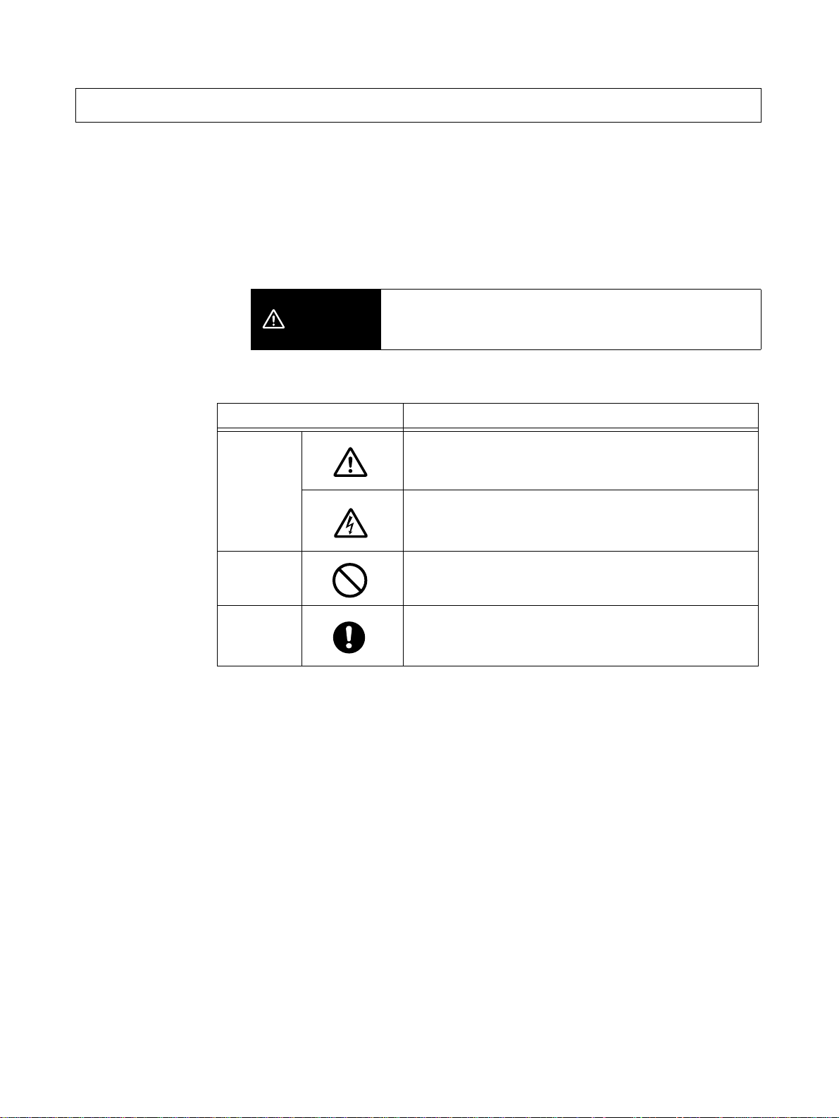
Safety Precaution s
■ Definition of Precautionary Information
The following notation is used in this manual to provide precau tions required
to ensure safe usage of the product.
The safety precautions that are provided are extremely importan t to safety.
Always read and heed the information provided in all safety precautions.
The following notation is used.
Indicates a potentially hazardous situation which, if not
CAUTION
■ Symbols
Symbol Meaning
Caution
avoided, is likely to result in minor or moderate injury or in
property damage.
General Caution
Indicates non-specific general cautions, warnings, and
dangers.
Electrical Shock Caution
Indicates possibility of electric shock under specific
conditions.
Prohibition
Mandatory
Caution
General Prohibition
Indicates non-specific general prohibitions.
General Caution
Indicates non-specific general cautions, warnings, and
dangers.
viii
Page 8
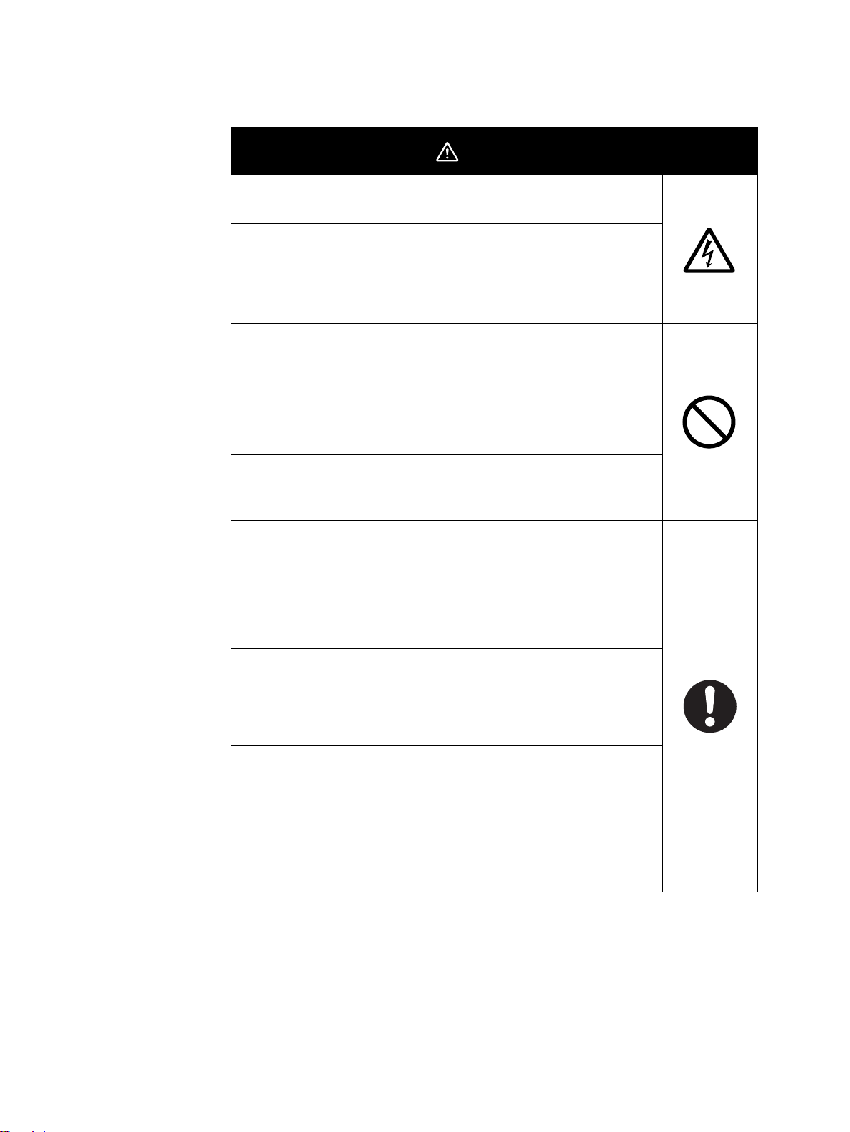
■ Safety Precautions
Do not touch the terminals while power is being supplied. Doing
so may occasionally result in minor injury due to electric shock.
Use a power supply that complies with the reinforced insulation
specified in IEC 60664 for the EJ1 external power supply or the
power supply connected to the EJ1. If non-compliant power
supplies are used, electric shock may occasionally result in minor
injury.
Do not allow pieces of metal, wire clippings, or fine metallic shavings or filings from installation to enter the product. Doing so may
occasionally result in electric shock, fire, or malfunction.
Do not use the product where subject to flammable or explosive
gas. Otherwise, minor injury from explosion may occasionally
occur.
Never disassemble, modify, or repair the product or touch any of
the internal parts. Minor electric shock, fire, or malfunction may
occasionally occur.
CAUTION
Tighten the terminal screws to between 0.40 and
0.56 N·m. Loose screws may occasionally result in fire.
Set the parameters of the product so that they are suitable for the
system being controlled. If they are not suitable, unexpected
operation may occasionally result in property damage or
accidents.
A malfunction in the product may occasionally make control
operations impossible or prevent alarm outputs, resulting in
property damage. To maintain safety in the event of malfunction of
the product, take appropriate safety measures, such as installing
a monitoring device on a separate line.
Gradient temperature control controls the average temperature for
more than one channel. If a heater burnout occurs during gradient
temperature control and the temperature of that channel
decreases, physical damage may occasionally occur because the
temperature of the other channels will incr ea se. When usi ng
gradient temperature control, implement suitable safety measures
for the entire system using heater burnout alarms or temperature
information for individual channels.
ix
Page 9

Precautions for Safe Use
Be sure to observe the following precautions to prevent operation failure, malfunction, or adverse affects on
the performance and functions of the product. Not doing so may occasionally result in unexpected events.
1) The product is designed for indoor use only. Do not use the product outdoors or in any of the following
locations.
• Places directly subject to heat radiated from heating equipment
• Places subject to splashing liquid or oil atmosphere
• Places subject to direct sunlight
• Places subject to dust or corrosive gas (in particular, sulfide gas or ammonia gas)
• Places subject to intense temperature change
• Places subject to icing or condensation
• Places subject to vibration or strong shocks
2) Use and store the product within the rated ambient temperature and humidity ranges.
Mounting two or m ore Temperature Co ntrollers side by side, or mountin g Temperature Co ntrollers above
each other may cause heat to build up inside the Temperature Controllers, which will shorten th eir se rvice
life. If the Temperature Controllers are mounted above each other or side by side, use forced cooling by
fans or other means of air ventilation to cool down the Temperature Controllers.
3) To allow heat to esc ape, do not block the area around th e product. Do not block the ventilation ho les on
the product.
4) Be sure to wire properly with correct polarity of terminals.
5) Use specified size (M3, width 5.8 mm or less) crimped terminal s for wiri ng. Use a gage of AWG22 to
AWG14 (equal to cross-sectional area of 0.326 to 2.081 mm
AWG28 to AWG16 (equal to cross-sectional a r ea o f 0.0 81 to 1.309 mm
length is 6 to 8 mm.) Up to two wires of same size and type, or two crimped terminals can be inserted into
a single terminal .
6) Do not wire terminals that do not have an identified use.
7) To reduce inductive noise, keep the wiring for the product's terminal block away from power cables
carrying high voltages or large currents. Also, do not wire power lines together with or parallel to product
wiring. Using shielded cables and using separate conduits or ducts is recommended.
Attach a surge suppressor or noise filter to peripheral devices that generate noise (in particular, motors,
transformers, solenoids, magnetic coils or other equipment that have an inductance component).
When a noise filter is used at the power supply, first check the voltage or current, and attach the noise
filter as close as possible to the product.
Allow as much space as possible between the product and devices that generate powerful high
frequencies (high-frequency welders, high-frequency sewing machines, etc.) or surge.
8) Use the product within the rated load and power supply.
9) Make sure that the rated voltage i s attained within two se co nds o f turning ON t he power us ing a switch or
relay contact. If the voltage is applied gradually, the power may not be reset or output malfunctions may
occur.
10) Make sure that the product has 30 minutes or more to warm up after turning ON the power before starting
actual control operations to ensure the correct temperature display.
11) The switch or circuit breaker must be within easy reach of the operator, and must be marked as a
disconnecting means for this unit.
12) Do not use paint thinner or similar chemical to clean with. Use standard grade alcohol.
13) Design the system (e.g., the control panel ) allowing leeway for the delay required before produ ct outputs
are valid after turning ON power to the product.
14) Never touch the electronic components, connect ors, or patter ns on prod uct boards wit h your bare hands.
Always hold the product by the case. Inap propria tely handl ing the pr oduct may occasi onally da mage
internal components due to static electricity.
2
) for power supply lines and a gage of
2
) for all other lines. (The s tripping
x
Page 10

15) Use a switch, relay, or other device with contacts to turn OFF the power supply quickly. Gradually lowering
the voltage of the power supply may result in incorrect outputs or memory errors.
16) Do not touch the elec tronic components with your hands or sub ject them to shock when removing the
terminal block.
17) Connect only the specified number of products in only a specified configuration.
18) Mount the product to a DIN Rail mounted vertically to the ground.
19) Always turn OFF the power supply before wiring the product, replacing the product, or changing the
product configuration.
20) Attach the enclosed cover seal to the connector opening on the left end Unit during installation.
21) Do not use port B on the End Unit when using port C on the HFU.
xi
Page 11

Precautions for Correct Use
● Installation
1) Do not connect an End Unit directly to an HFU.
2) Always connect an End Unit to the right side of the Basic Units.
3) Always connect the HFU to the left side of the Basic Units.
4) The EJ1 cannot be used linked to a CJ-series PLC.
5) Use the EJ1G-@@ for gradie nt temperature control. Use the EJ1N-@@ for any other type of temperature
control.
6) When removing the terminal block to replace the Unit, be sure to confirm that the new Unit is the same as
the Unit that is being replaced.
● Service Life
1) Use the product within the following temperature and humidity ranges.
Temperature:
Humidity: 25% to 85%
When the Temperature Controller is incorporated in a control panel, make sure that the controller’s
ambient temperature and not the panel’s ambient temperature does not exceed 55
2) The service life of electronic d evices like the Tem perature Controller is deter mined by the ser vice life of
internal electronic components. Component service life is affected by the ambient temperature: the higher
the temperature, the shor ter the service life and the lower the temperature, the longer the service life.
Therefore, the service life can be extended by lowering the temperature of the Temperature Controller.
3) Mounting two or more Temperature Co ntrollers sid e by side, or moun ting Temperature Controllers a bove
each other may cause heat to build up inside the Temperature Controllers, which will shorten th eir se rvice
life. If the Temperature Controllers are mounted above each other or side by side, use forced cooling by
fans or other means of air ventilation to cool down the Temperature Controllers. However, be sure not to
cool only the terminals. Doing so will result in measurement errors.
−10 to 55°C (with no icing or condensation)
°C.
● Ensuring Measurement Accuracy
1) When extending or connecting the thermocouple lead wire, be sure to use compensating wires that match
the thermocouple types.
2) When extending or connecting the lead wire of the pl ati num re si st ance thermometer, be sure to use wires
that have low resistance and keep the resistance of the three lead wires the same.
3) Mount the Temperature Controller so that it is horizontally level.
4) If the measurement accuracy is low, check to see if input shift has been set correctly.
● Precautions for Operation
1) It takes a certain amount of time for the outputs to turn ON from after the power supply is tu rned ON. Due
consideration must be given to this time when designing control panels, etc.
2) It takes 30 minutes from the time the product is turned ON until the correct temperature is indicated.
Always turn ON the power supply at least 30 minutes before starting temperature control.
3) Avoid using the Temperat ure Con tr oll er near a radio, television set, or other wireless device. Its use would
result in reception disturbance.
xii
Page 12

Preparations for Use
Be sure to thoroughl y read and under stand the manual provide d with the product, and check the following points.
Timing Check point Details
Purchasing the product Product appearance After purchase, check that the product and packaging are not dented
or otherwise damaged. Damaged internal parts may prevent optimum
control.
Product model and
specifications
Setting the Unit Product installation
location
Wiring Terminal wiring Do not subject the terminal screws to excessive stress (force) when
Power supply inputs Wire the power supply inputs correctly. Incorrect wiring will result in
Operating environment Ambient temperature The ambient operating tem perature f or the product is −10 to 55°C (with
Vibration and shock Check whether the standards related to shock and vibration are satis-
Foreign particles Install the product in a location that is not subject to liquid or foreign
Make sure that the purchased product meets the required specifications.
Provide sufficient space around the product for heat dissipation. Do
not block the vents on the product.
tightening them.
Make sure that there are no loose screws after tightening terminal
screws to the specified torque of 0.40 to 0.56 N·m.
Be sure to confirm the polarity for each terminal before wiring the ter-
minal block and connectors.
damage to the internal circuits.
no condensation or icing). To extend the serv ice life of the product,
install it in a location with an ambient temperature as low as possible.
In locations exposed to high temperatures, if necessary, cool the products using a fan or other cooling method.
fied at the installation environment. (Install the product in locations
where the conductors will not be subject to vibration or shock.)
particles entering the product. If sulfide, chlorine, or other corrosive
gases are present, remove the source of the gas, install a fan, or use
other countermeasures to protect the product.
xiii
Page 13

Related Manuals
The manuals related to the EJ1G are co nfi gured as shown in the following tables. Refer to these manuals as required.
■ EJ1G
Name Cat. No. Contents
EJ1G
EJ1G-TC2A-QNHB
EJ1G-TC4A-QQ
EJ1G-HFUA-NFLK
EJ1C-EDUA-NFLK
Modular Temperature Controllers for Gradient Temperature
Control User's Manual
CX-Thermo Ver. 3.@ (online help)
EST2-2C-MV3
■ CS/CJ-series PLC Manuals
Name Cat. No. Contents
SYSMAC CS Series
CS1G/H-CPU@@-EV1, CS1G/H-CPU@@H
Programmable Controllers Operation Manual
SYSMAC CJ Series
CJ1G-CPU@@, CJ1M-CPU@@, CJ1G-CPU@@P,
CJ1G/H-CPU@@H
Programmable Controllers Operation Manual
SYSMAC CS/CJ Series
CS1G/H-CPU@@-EV1, CS1G/H-CPU@@H, CS1DCPU@@H, CS1D-CPU@@S, CJ1G-CP U@@, CJ1MCPU@@, CJ1G-CPU@@P, CJ1G/H-CPU@@H
Programmable Controllers Programming Manual
SYSMAC CS/CJ Series
CS1G/H-CPU@@-EV1, CS1G/H-CPU@@H, CS1DCPU@@H, CS1D-CPU@@S, CJ1G-CP U@@, CJ1MCPU@@, CJ1G-CPU@@P, CJ1G/H-CPU@@H
Programmable Controllers Instructions Reference Manual
SYSMAC CS/CJ Series
CS1G/H-CPU@@-EV1, CJ1G/H-CPU@@H, CS1DCPU@@H, CS1D-CPU@@S, CJ1G-CP U@@, CJ1GCPU@@, CJ1M-CPU@@, CJ1G-CPU@@P, CJ1G/HCPU@@H, CS1W-SCB21-V1/ 41-V1 , CS1W-SCU21-V1,
CJ1W-SCU21-V1/41-V1
Communications Commands Reference Manual
SYSMAC CS/CJ Series
CS1W-SCB21-V1/41-V1, CS1W-SCU21-V1, CJ1WSCU21-V1/41-V1
Serial Communications Boards/Units Operation Manual
H143
(This
manual)
--(Available
only as
online
help.)
W339 Provides an outlines of and describes the design,
W393 Provides an outlines of and describes the design,
W394 Describes prog ramming and other methods to use
W340 Describes the ladder dia g ram programming
W342 Describes the C- se ries (Hos t Lin k) a nd FINS c om -
W336 Describes the use of Serial Communications Unit
Describes the following information on the EJ1G .
• Overview and features
• Basic specifications
• System design
• System configuration
• Mounting and wiring
• Maintenance
• Troubleshooting
Describes how to set paramet ers and adjus t
devices (i.e., components such as Temperature
Controllers) using the CX-Thermo.
installation, maintenance, and other basic operations for the CS-series PLCs.
installation, maintenance, and other basic operations for the CJ-series PLCs.
the functions of the CS/CJ-series PLCs.
instructions supported by CS/CJ-series PLCs.
munications commands used with CS/CJ-series
PLCs.
and Boards to perf orm serial commu nication s with
external devices, including the usage of standard
system protocols for OMRON products.
xiv
Page 14

■ Programmable Terminal (PT) Manuals
Name Cat. No. Contents
NS-Series
NS5-SQ0@(B)-V1/V2, NS5-TQ0@(B)-V2,
NS5-MQ0@(B)-V2, NS8-TV@@(B)-V1/V2,
NS10-TV0@(B)-V1/V2, NS12-TS0@(B)-V1/V2
Programmable Terminals Setup Manual
NS-Series
NS5-SQ0@(B)-V1/V2, NS5-TQ0@(B)-V2,
NS5-MQ0@(B)-V2, NS8-TV@@(B)-V1/V2,
NS10-TV0@(B)-V1/V2, NS12-TS0@(B)-V1/V2
Programmable Terminals Programming Manual
SYSMAC One NSJ Series
NSJ5-TQ@@(B)-G5D, NSJ5-SQ@@(B)-G5D, NSJ8-
TV@@(B)-G5D, NSJ10-TV@@(B)-G5D, NSJ12-TS@@(B)-
G5D, NSJW-ETN21, NSJW-CLK21-V1, NSJW-IC101
NSJ Controllers Operation Manual
NSH Series
NSH5-SQR00B-V2
Hand-held Programmable Terminal Operation Manual
NS Series
NS-CA002
Programmab l e Terminals RGB and Video Input Unit Opera tion Manual
Smart Active Parts Reference Manual V087
V083 Provides an outline of, and describes the design,
V073 Describes the functions of NS-series PTs, includ-
W452 Provides an outline o f, and describes the design,
W452 Provides an outline o f, and describes the design,
V086
(PDF
only)
(PDF
only)
installation, maintenance, and other basic operations for the NS-series PTs. Information is also
included on connecti ng to host s and periphe ral
devices , and settings required f or c ommunic ations
and PT operation.
ing screen configurations, object functions, and
host communications for the PT.
installation, maintenance, and other basic operations for the NSJ-series NSJ Controllers. Information is also included on features, system
configuration, wiring, I/O memory allocations, and
troubleshooting.
Use together with the CJ-series Programmable
Controllers Oper ati on Ma n ual (W393), CS/CJseries Programmable Controllers Programming
Manual (W394), and NS-Series Programmable
Terminals Setup Manual (V083).
installation, maintenance, and other basic operations for the NSH-series NSH5 Hand-held Programmable Terminal. Information is also included
on features, system configuration, wiring, I/O
memory allocations, and troubleshooting.
Describes how to di spla y e xte rnal video images or
analog RGB imagines on NS-series PTs using a
NS-series RGB and Video Input Unit, including the
followi ng information.
• Features, system configuration, and specifications
• Functions, setting methods, and adjustment
methods
Describes the Smart Active Parts (SAP) functionality and the settings required to use the SAP
library. This document does not describe application restrictions for specific Units or Components
or restrictions in comb ina t io ns. Always ref er to th e
operation manual for the products involved before
using the SAP library.
xv
Page 15

■ Support Software Manuals
Name Cat. No. Contents
CX-One
CXONE-AL@@C-E
Setup Manual
CX-Integrator
CXONE-AL@@C-E
Operation Manual
CX-Programmer Ver. 6.1
WS02-CXPC1-E-V60
Operation Manual
CX-Programmer Ver. 6.1
WS02-CXPC1-E-V60
CS1G-CPU@@H
CS1H-CPU@@H
CJ1G-CPU@@H
CJ1H-CPU@@H
CJ1M-CPU@@
CP1H-X@@@@-@
CP1H-XA@@@@-@
Operation Manual: Function Blocks
SYSMAC CX-Designer Ver. 1.0
NS-CXDC1-V1
Operation Manual
NS-Series
NS5-SQ0@(B)-V1/V2
NS5-TQ0@(B)-V2
NS5-MQ0@(B)-V2
NS8-TV@@(B)-V1/V2
NS10-TV0@(B)-V1/V2
NS12-TS0@(B)-V1/V2
NSJ5-TQ@@(B)-G5D
NSJ5-SQ@@(B)-G5D
NSJ8-TV@@(B)-G5D
NSJ10-TV@@(B)-G5D
NSJ12-TS@@(B)-G5D
Ladder Monitor Operation Manual (Ladder Monitor/I/O
Comment Extracting Tool)
W444
(PDF
only)
W445 Describes CX-Integrator operating methods, e.g.,
W446 Describes CX-Programmer operations except
W447 Describes function blocks for CS/CJ-series CPU
V088 Describes how to inst all and us e the CX-De signer,
V082 Describes the NS-series PT monitoring function
Describes installa tion and pro vid es an ov erview of
the CX-One FA Integrated Tool Package.
for setting up and monitoring networks.
those related to function blocks.
Units unit version 3.0 or later and CP-series CPU
Units, and CX-Programmer operations related to
function blocks.
Refer to the W447 manual above for other CXProgrammer operations.
including screen data creation methods, screen
data transfer methods, and system settings.
for CS/CJ-series PLC ladder programs, including
the following information.
• Overview and features
• Setup methods
• Basic operations
• Troubleshooting
xvi
Page 16

Conventions Used in Th is Manual
Meanings of Abbreviations
The following abbreviations are used in parameter names, figures and in text explanations. These
abbreviations mean the following:
Symbol Term
TC4/TC2 Four-channel and Two-channel Basic Units
CH Channel
HFU Advanced Unit
EDU End Unit
PV Process value
SP Set point
HB Heater burnout
HS Heater short
GT Gradient tuning
GTC Gradient temperature control
OC Heater overcurrent
AT Autotuning
EU Engineering unit (See note 1.)
Expand Unit Expansion Unit (See note 2.)
Note: (1) “EU” stands for Engineering Unit. EU is use d as the minimum unit for engineer ing units suc h as
m, and g. The size of EU varies according to the input type.
For example, when the input temperature setting range is –200 to +1300
the input temperature setting range is –20.0 to +500.0
For analog inputs, the size of EU varies according to the decimal point position of the scaling setting,
and 1 EU becomes the minimum scaling unit.
(2) "Ex pand Unit" in parameter and status names that appear in this manual mea ns "Expansion Unit,"
which is a Unit, such as the G3ZA Multi-channel Power Controller, connected to a Basic Unit.
°C, 1 EU is 0.1°C.
°C, 1 EU i s 1 °C, and whe n
°C,
xvii
Page 17

xviii
Page 18

TABLE OF CONTENTS
SECTION 1
Outline . . . . . . . . . . . . . . . . . . . . . . . . . . . . . . . . . . . . . . . . . . . 1
1-1 Names of Parts. . . . . . . . . . . . . . . . . . . . . . . . . . . . . . . . . . . . . . . . . . . . . . . . . . . . . . . . . . . . 2
1-2 I/O Configuration and Main Functions . . . . . . . . . . . . . . . . . . . . . . . . . . . . . . . . . . . . . . . . . 5
1-3 Internal Block Diagrams . . . . . . . . . . . . . . . . . . . . . . . . . . . . . . . . . . . . . . . . . . . . . . . . . . . . 9
SECTION 2
Preparations . . . . . . . . . . . . . . . . . . . . . . . . . . . . . . . . . . . . . . 11
2-1 Installation . . . . . . . . . . . . . . . . . . . . . . . . . . . . . . . . . . . . . . . . . . . . . . . . . . . . . . . . . . . . . . . 12
2-2 Wiring Terminals . . . . . . . . . . . . . . . . . . . . . . . . . . . . . . . . . . . . . . . . . . . . . . . . . . . . . . . . . . 16
2-3 Using Tool Ports . . . . . . . . . . . . . . . . . . . . . . . . . . . . . . . . . . . . . . . . . . . . . . . . . . . . . . . . . . 25
2-4 Unit Configuration Examples . . . . . . . . . . . . . . . . . . . . . . . . . . . . . . . . . . . . . . . . . . . . . . . . 26
SECTION 3
Gradient Temperature Control Setup . . . . . . . . . . . . . . . . . 33
3-1 Setup Procedure. . . . . . . . . . . . . . . . . . . . . . . . . . . . . . . . . . . . . . . . . . . . . . . . . . . . . . . . . . . 34
3-2 Adjusting Gradient Temperature Control . . . . . . . . . . . . . . . . . . . . . . . . . . . . . . . . . . . . . . . 46
3-3 Changing SPs During Operation . . . . . . . . . . . . . . . . . . . . . . . . . . . . . . . . . . . . . . . . . . . . . . 47
SECTION 4
Basic Units (TC4 and TC2) Functions . . . . . . . . . . . . . . . . . 49
4-1 Setting Input Specifications. . . . . . . . . . . . . . . . . . . . . . . . . . . . . . . . . . . . . . . . . . . . . . . . . . 50
4-2 Setting Output Specifications . . . . . . . . . . . . . . . . . . . . . . . . . . . . . . . . . . . . . . . . . . . . . . . .53
4-3 Setting Control Specifications. . . . . . . . . . . . . . . . . . . . . . . . . . . . . . . . . . . . . . . . . . . . . . . .54
4-4 Detecting Current Errors . . . . . . . . . . . . . . . . . . . . . . . . . . . . . . . . . . . . . . . . . . . . . . . . . . . . 55
4-5 Other Functions . . . . . . . . . . . . . . . . . . . . . . . . . . . . . . . . . . . . . . . . . . . . . . . . . . . . . . . . . . . 56
SECTION 5
Advanced Unit (HFU) Functions. . . . . . . . . . . . . . . . . . . . . . 61
5-1 Setting Input Specifications. . . . . . . . . . . . . . . . . . . . . . . . . . . . . . . . . . . . . . . . . . . . . . . . . . 62
5-2 Setting Output Specifications . . . . . . . . . . . . . . . . . . . . . . . . . . . . . . . . . . . . . . . . . . . . . . . .66
5-3 Setting Control Specifications. . . . . . . . . . . . . . . . . . . . . . . . . . . . . . . . . . . . . . . . . . . . . . . .67
5-4 Setting Alarm Specifications. . . . . . . . . . . . . . . . . . . . . . . . . . . . . . . . . . . . . . . . . . . . . . . . .83
5-5 Detecting Current Errors . . . . . . . . . . . . . . . . . . . . . . . . . . . . . . . . . . . . . . . . . . . . . . . . . . . . 88
5-6 Programless Communications. . . . . . . . . . . . . . . . . . . . . . . . . . . . . . . . . . . . . . . . . . . . . . . . 93
5-7 Other HFU Functions . . . . . . . . . . . . . . . . . . . . . . . . . . . . . . . . . . . . . . . . . . . . . . . . . . . . . . 121
xix
Page 19

TABLE OF CONTENTS
SECTION 6
Communications (CompoWay/F) . . . . . . . . . . . . . . . . . . . . . 125
6-1 Communications Settings . . . . . . . . . . . . . . . . . . . . . . . . . . . . . . . . . . . . . . . . . . . . . . . . . . .126
6-2 Frame Configuration . . . . . . . . . . . . . . . . . . . . . . . . . . . . . . . . . . . . . . . . . . . . . . . . . . . . . . . 128
6-3 FINS-mini Text . . . . . . . . . . . . . . . . . . . . . . . . . . . . . . . . . . . . . . . . . . . . . . . . . . . . . . . . . . . 130
6-4 Detailed Description of Services . . . . . . . . . . . . . . . . . . . . . . . . . . . . . . . . . . . . . . . . . . . . . . 132
SECTION 7
Errors and Error Processing . . . . . . . . . . . . . . . . . . . . . . . . . 147
7-1 Things to Check First . . . . . . . . . . . . . . . . . . . . . . . . . . . . . . . . . . . . . . . . . . . . . . . . . . . . . . 148
7-2 Determining Errors from Indicators . . . . . . . . . . . . . . . . . . . . . . . . . . . . . . . . . . . . . . . . . . . 149
7-3 Determining the Error from the Status . . . . . . . . . . . . . . . . . . . . . . . . . . . . . . . . . . . . . . . . . 151
7-4 Determining the Error from the Current Situation for Communications Errors . . . . . . . . . . 158
7-5 Determining the Error from the Current Situation for Temperature Measurement Errors . . 163
7-6 Determining the Error from the Current Situation for Temperature Control Errors . . . . . . . 164
7-7 Determining the Error from the Current Situation for Output Errors . . . . . . . . . . . . . . . . . . 166
7-8 Determining the Error from the Current Situation for Heater Burnout Alarm Errors. . . . . . 167
Appendix . . . . . . . . . . . . . . . . . . . . . . . . . . . . . . . . . . . . . . . . . 169
Index. . . . . . . . . . . . . . . . . . . . . . . . . . . . . . . . . . . . . . . . . . . . . 209
Revision History . . . . . . . . . . . . . . . . . . . . . . . . . . . . . . . . . . . 215
xx
Page 20

About this Manual:
This manual describes the EJ1G Modular Temperature Controllers and includes the sections
described below.
Please read this manual carefully and be sure you understand the information provided before
attempting to set up or operate an EJ1G Modular Temperature Controller.
•Overview
Section 1 Outline describes the features, nomenclature, and functions of the EJ1G.
•Setup
Section 2 Preparations describes the preparations requ ired to use the EJ1G, includi ng installation,
wiring, and switch settings.
•Gradient Temperature Control Setup
Section 3 Gradient Temperature Control Setup describes how to set up and adjust gradient temperature control and how to change the SPs during operation.
•Functions of EJ1G Basic Units (TC4/TC2)
Section 4 Basic Units (TC4/TC2) describes the functions of EJ1G Basic Units.
•Functions of EJ1G Advanced Unit (HFU)
Section 5 Advanced Unit (HFU) Functions describes the functions of EJ1G Advanced Unit.
•Operation Using Communications
Section 6 Communications (CompoWay/F) descr ibes how to use communications based on communications commands.
•Troubleshooting
Section 7 Troubleshooting describes met hods for checking possible problems in operati on depending on classifications of Temperature Controller status.
•Specifications and Parameter Lists
Appendix provides specifications, parameter lists, status lists, and other reference information.
!WARNING Failure to read and under stand the informati on provided i n this ma nual may result in p er-
sonal injury or death, damage to the product, or product failure. Please read each sec ti on
in its entirety and be sure you understand the information provided in the section and
related sections before attempting any of the procedures or operations given.
xxi
Page 21

xxii
Page 22

This section describes the features, nomenclature, and functions of the EJ1G.
1-1 Names of Parts . . . . . . . . . . . . . . . . . . . . . . . . . . . . . . . . . . . . . . . . . . . . . . . . 2
1-1-1 Appearance . . . . . . . . . . . . . . . . . . . . . . . . . . . . . . . . . . . . . . . . . . . . 2
1-1-2 Names of Parts on Front Panel . . . . . . . . . . . . . . . . . . . . . . . . . . . . . 2
1-1-3 Meanings of Indicators. . . . . . . . . . . . . . . . . . . . . . . . . . . . . . . . . . . 2
1-1-4 Using Setting Switches. . . . . . . . . . . . . . . . . . . . . . . . . . . . . . . . . . . 3
1-2 I/O Configuration and Main Functions. . . . . . . . . . . . . . . . . . . . . . . . . . . . . . 5
1-2-1 I/O Configuration . . . . . . . . . . . . . . . . . . . . . . . . . . . . . . . . . . . . . . . 5
1-2-3 Main Unit Functions. . . . . . . . . . . . . . . . . . . . . . . . . . . . . . . . . . . . . 6
1-2-4 Model Number Legend. . . . . . . . . . . . . . . . . . . . . . . . . . . . . . . . . . . 7
1-3 Internal Block Diagrams. . . . . . . . . . . . . . . . . . . . . . . . . . . . . . . . . . . . . . . . . 9
SECTION 1
Outline
1
Page 23
Names of Parts Section 1-1
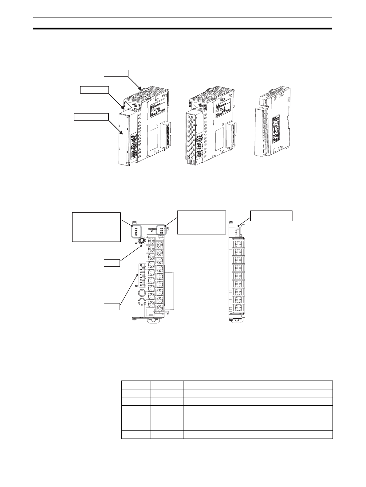
1-1 Names of Parts
1-1-1 Appearance
Slider
Front panel
Terminal block
TC4, TC2, or HFU
Screw Terminals
1-1-2 Names of Parts on Front Panel
Operation Indicators
PWR
RUN
ERR
ALM
SW1
SW2
TC4, TC2, or HFU EDU
Operation Indicators
COM1
COM2
COM3
1-1-3 Meanings of Indicators
TC4, TC2, or HFU
Screw-Less Clamp Terminals
EDU
Port A connector
Operation Indicators
TC4 and TC2
2
Name Color Meaning
PWR Green Lights when the power is ON.
ERR Red Flashes or lights when an error occurs.
ALM Red Lights when an alarm is activated.
COM1 Orange Flashes during communications via port A on the End Unit.
COM2 Orange Flashes when the EJ1G system is in operation.
COM3 Orange Flashes during communications with the G3ZA.
Page 24
Names of Parts Section 1-1
HFU
Name Color Meaning
PWR Green Lights when the power is ON. (See note.)
RUN Green Lights during operation.
ERR Red Flashes or lights when an error occurs.
ALM Red Lights when an alarm is activated.
COM1 Orange Flashes during communications via port A on the End Unit.
COM2 Orange Flashes when the EJ1G system is in operation.
COM3 Orange Flashes during communications via port C.
Note Some time is required for the indicators to light after the power is turned ON.
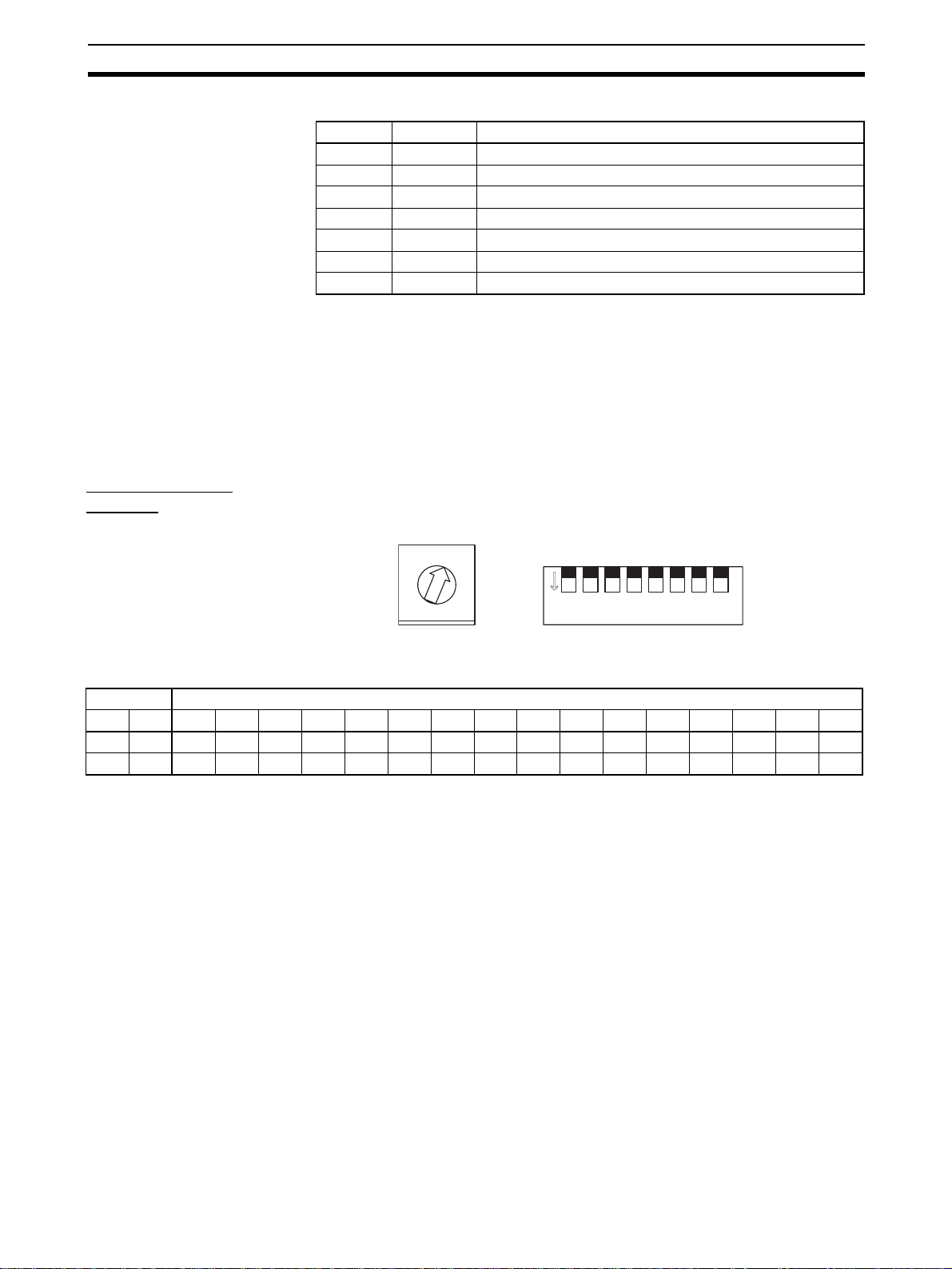
1-1-4 Using Setting Switches
• Check that the EJ1G is turne d OFF before opera ting the switches. The
settings are enabled when the power is turned ON.
• Set the switches with a small flat-blade screwdriver. Do not set the
switches midway between settings.
Setting the Unit
Number
Unit Number Settings
SW2 SW1
120123456789ABCDEF
OFF OFF 00 01 02 03 04 05 06 07 08 09 10 11 12 13 14 15
ONOFF16171819202122232425262728293031
SW1 and SW2 are used toge ther to set the unit number to between 00 and
31.
Note The factory setting is unit number 01.
0
1
2
F
3
E
4
D
5
C
6
B
7
A
8
9
SW1 SW2
1 2 3 4 5 6 7 8
ON
3
Page 25
Names of Parts Section 1-1
Setting Switch 2
(SW2) Settings
EJ1G-TC Basic Units
SW2 Meaning
2 to 6 Not used (OFF)
7 ON: G3ZA Multi-channel Power Controller in operation
8 Use when an HFU is used and Units are distributed. (See note.)
Note To us e a n HF U with d is tr ibuted po si ti oni ng, t urn ON pin number 8 on SW 2 o n
the TC Unit connected at the left end of the Block.
Refer to SECTION 2 Preparations for information on wiring.
EJ1G-HFU (Advanced
Unit)
HFU
TC4/2
SW2 Meaning
2 to 7 Not used (OFF)
8•EJ1G-HFU@-NFLK
EDU
TC4/2
Turn ON pin 8 on SW2.
OFF: RS-485 is selected.
ON: RS-232C is selected.
•EJ1G-HFU@-NFL2
Not used (O FF).
TC4/2
EDU
TC4/2
Turn ON pin 8 on SW2.
TC4/2
TC4/2
EDU
4
Page 26
I/O Configuration and Main Functions Section 1-2
1-2 I/O Configuration and Main Functions
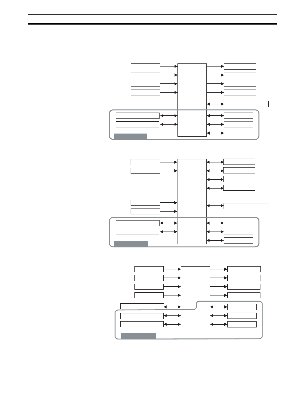
1-2-1 I/O Configuration
TC4: Four-channel Basic
Unit
Main input 1
Main input 2
Main input 3
Main input 4
Control
section
Control output 1
Control output 2
Control output 3
Control output 4
G3ZA communications
TC2: Two-channel Basic
Unit
HFU (Advanced Unit)
Port A communications
Port B communications
Inside the device
Internal bus 1
Internal bus 2
Internal bus 3
• Internal device I/O are connected via a connector to the adjacent Unit.
Main input 1
Main input 2
CT input 1
CT input 2
Port A communications
Port B communications
Inside the device
Control
section
Control output 1
Control output 2
Control output 3
Control output 4
G3ZA communications
Internal bus 1
Internal bus 2
Internal bus 3
• Internal device I/O are connected via a connector to the adjacent Unit.
Event input 1
Event input 2
Event input 3
Event input 4
Control
section
Auxiliary output 1
Auxiliary output 2
Auxiliary output 3
Auxiliary output 4
Port C communications
Port A communications
Port B communications
Inside the device
Internal bus 1
Internal bus 2
Internal bus 3
• Internal device I/O are connected via a connector to the adjacent Unit.
5
Page 27

I/O Configuration and Main Functions Section 1-2
EDU: End Unit
Adjacent Unit
Port A communications
Port B communications
Auxiliary output 1 (See note.)
Auxiliary output 2 (See note.)
Note Auxiliary outputs are output via an internal bus.
1-2-2 What Is Gradient Temperature Control?
Gradient temperature control is a control method that achieves a uniform temperature or preset temperature profile over a 2D surface. An example application would be multi-point control of surface temperature using multiple
heaters. The gradient temperature control algorithm directly controls the average temperature of all point s as well as the temperature difference between
each pair of points. The algorithm also includes methods to eliminate the
interference of each control output on the other control points.
Suppresses interference of
Gradient T emper ature Control
control outputs on other points.
Controls average
temperature.
When temperature inputs are received, the average temperature of all poi nts
and the temperature differences be tween each pair of points are ca lculated.
PID control is performed for the present value (PV) of eac h of these control
points.
In addition, PID o utput values are distributed to prevent them from affecting
PID control performance at other poin ts, thus eliminating interference. This
means that the inte rference of heaters on other control points is reduced to
enable uniform in-plane temperature control.
1-2-3 Main Unit Functions
Basic Units (TC4 and
TC2)
• Basic Units are used as the control I/O devices. (The HFU performs control processing.)
• There are two models of Basic Unit: The TC4 with four I/O channels an d
the TC2 with two I/O channels.
• Universal input supports a ther m ocoupl e, platinum resis tance thermometer, or analog input.
• The type of input can be set separately for each channel.
• Control outputs are pulse voltage outputs.
Controls temperature
differences.
6
Page 28
I/O Configuration and Main Functions Section 1-2
• Terminal blocks can be detached and attached. Both screw terminals and
screw-less clamp terminals are available.
• Connect a current transformer (CT) to use t he heater burno ut and heater
overcurre nt alarms (TC2 Units only).
• Up to eight G3ZA Multi-cha nnel Power Controlle rs can be connected to
one Basic Unit.
Advanced Unit (HFU) • The HFU performs gradient temperat ure control or 2-PID con trol (set for
each group).
• Gradient temperature control can be performed for from 2 to 32 channels.
(2-PID control can also be set by group for from 2 to 32 channels.)
• Two-channel gradient temperature control can be performed for up to 16
groups (when TC4 and TC2 U nits are used) or 3 2-channel gradient temperature control can be performed for up to 2 groups (when TC4 Units are
used).
• Up to sixteen Basic Units can be connected to one HFU.
• Data can be exchanged between the EJ1G and PLCs using programless
communications.
• Up to 300 data items can be re ad from a PLC to the EJ 1G and u p to 300
data items can be written from the EJ1G to a PLC.
• OMRON CS/CJ-series PLCs and Mitsubishi Q/QnAS-series PLCs can be
connected.
End Unit (EDU) • The End Unit supplies power to connected Basic Units and HFUs.
• An End Unit is always required when using the EJ1G.
• A total of up to 16 HFUs and Basic Units can be conn ected to one End
Unit.
• Port A is split into both a connector and a terminal block. The connector is
used with the Suppor t Software and the ter minal block is used for EJ1G
distributed placement. (Port B is also used for distributed placement.)
• When using port A, be sure to consider the write life of the EEPROM.
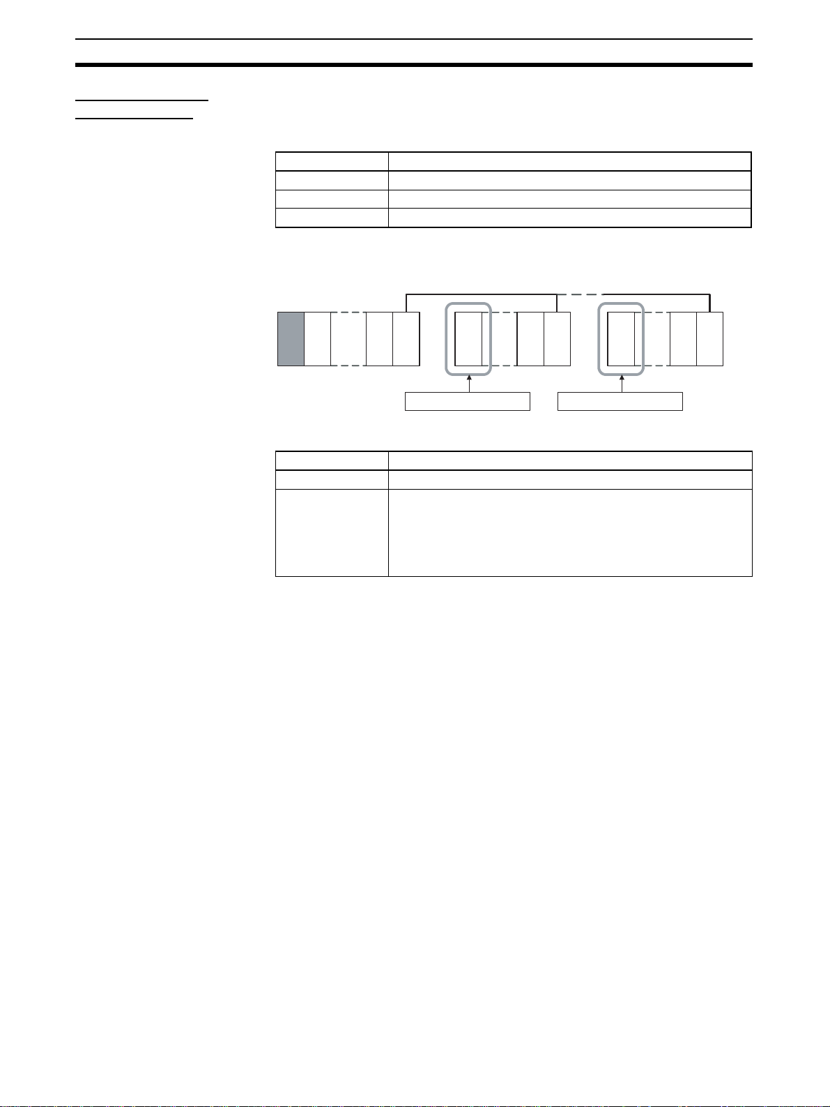
1-2-4 Model Number Legend
TC4 and TC2
Options
Outputs
Terminal
type
Unit name
Type Gradient Temperature Control
None
H
B
Q
N
A
B
T C 4
T C 2
G
2 CT inputs
2 event inputs
2 pulse voltage outputs
2 transistor outputs
Screw terminals
Screw-less clamp terminals
Four-channel Temperature Control Unit
Two-channel Temperature Control Unit
1 2 3 4 5 6 7 8 9 10 11 12 13 14
G - T C 4 A Q Q1JE G - T C 4 B Q Q1JE G - T C 2 A Q N H B1JE G - T C 2 B Q N H B1JE -
7
Page 29
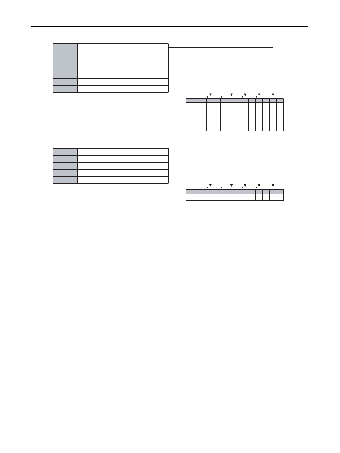
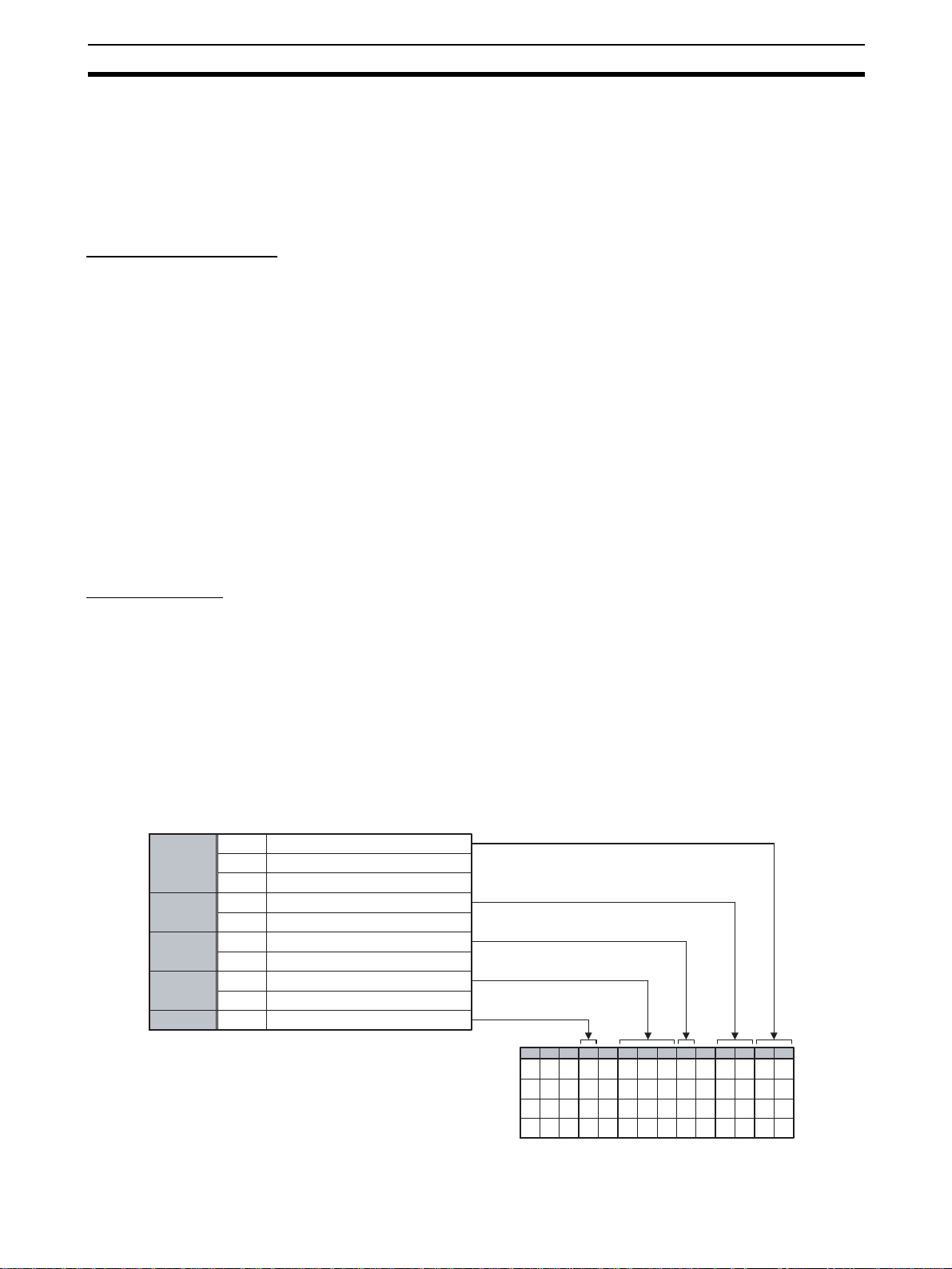
I/O Configuration and Main Functions Section 1-2
HFU
Communications
Outputs
Terminal
type
Unit name
Type
EDU
Communications
Outputs 2 transistor outputs
Terminal type
Unit name
Type
FLK
FL2
N
A
B
HFU
G
FLK
N
A
EDU
C
CompoWay/F (RS-485/RS-232C)
CompoWay/F (RS-422)
4 transistor outputs
Screw terminals
Screw-less clamp terminals
Advanced Unit
Gradient Temperature Control
CompoWay/F
Screw terminals
End Unit
Common model
1 2 3 4 5 6 7 8 9 10 11 12 13 14
G - H F U A N F1JE G - H F U A N F1JE G - H F U B N F L K1JE G - H F U B N F L 2
1JE -
LK
L2
1 2 3 4 5 6 7 8 9 10 11 12 13 14
C - E D U A N F L K1JE -
8
Page 30
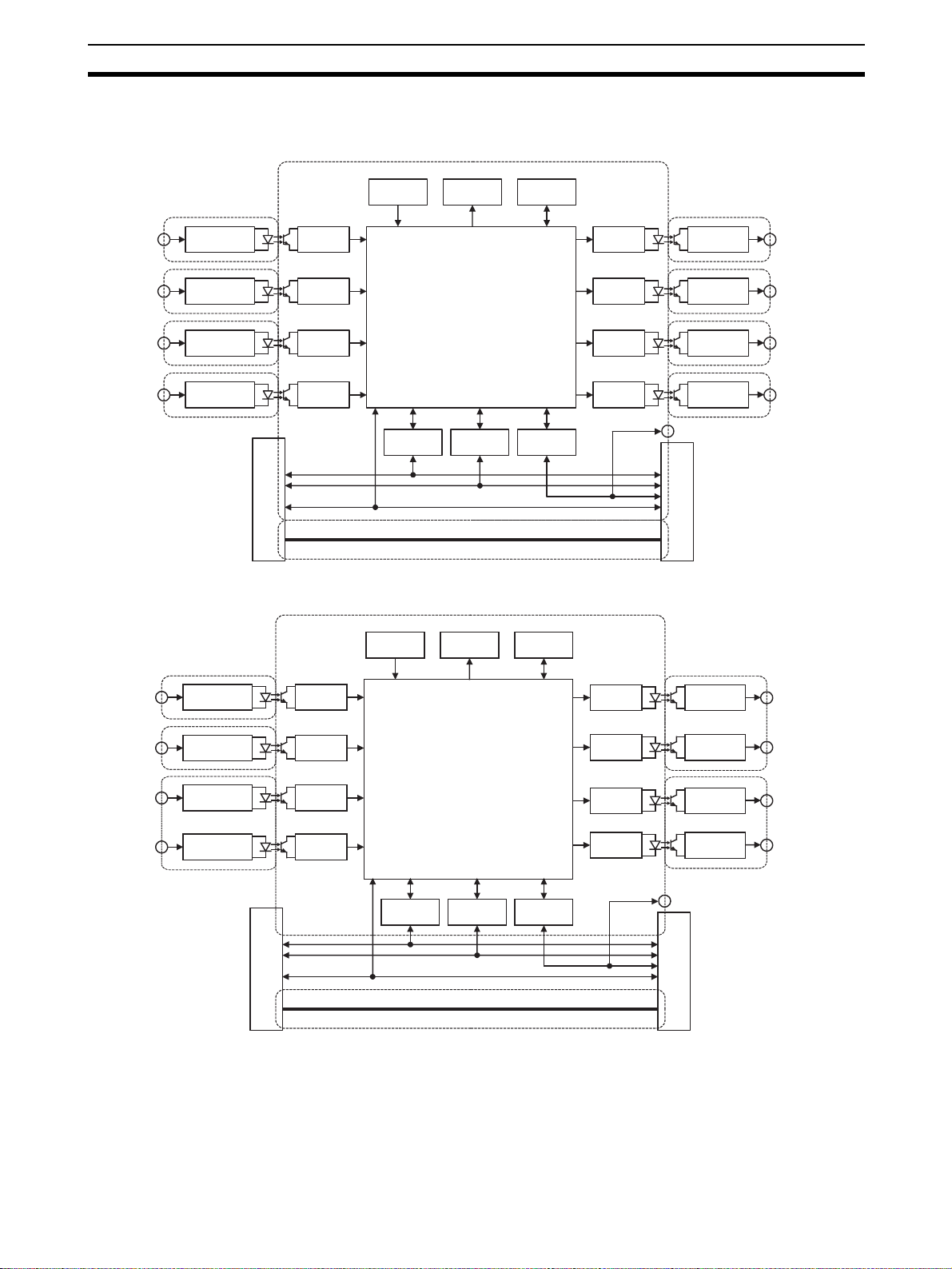
Internal Block Diagrams Section 1-3
1-3 Internal Block Diagrams
TC4
Main input 1
Main input 2
Main input 3
Main input 4
TC2
Temperature/analog input circuit
Temperature/analog input circuit
Temperature/analog input circuit
Temperature/analog input circuit
Waveform
shaping
circuit
Waveform
shaping
circuit
Waveform
shaping
circuit
Waveform
shaping
circuit
Connector between Units
Switch
inputs
Port A communications circuit
Switch
inputs
Indicators
Microcomputer
Port B communications circuit
Internal buses 1 to 3
24 VDC
Indicators
EEPROM
G3ZA communications circuit
EEPROM
Drive
circuit
Drive
circuit
Drive
circuit
Drive
circuit
Pulse voltage
outputs
Pulse voltage
outputs
Pulse voltage
outputs
Pulse voltage
outputs
G3ZA communications
Connector between Units
Control output 1
Control output 2
Control output 3
Control output 4
Main input 1
Main input 2
CT input 1
CT input 2
Temperature/analog input circuit
Temperature/analog input circuit
CT input circuit
CT input circuit
Waveform
shaping
circuit
Waveform
shaping
circuit
Waveform
shaping
circuit
Waveform
shaping
circuit
Connector between Units
Port A communications circuit
Microcomputer
Port B communications circuit
Internal buses 1 to 3
24 VDC
G3ZA communications circuit
Drive
circuit
Drive
circuit
Drive
circuit
Drive
circuit
Pulse voltage
outputs
Pulse voltage
outputs
Transistor
outputs
Transistor
outputs
G3ZA communications
Connector between Units
Control output 1
Control output 2
Control output 3
Control output 4
9
Page 31

Internal Block Diagrams Section 1-3
3
HFU
Event input 1
Event input 2
Event input 3
Event input 4
EDU
Event input
circuit
Event input
circuit
Event input
circuit
Event input
circuit
Waveform
shaping
circuit
Waveform
shaping
circuit
Waveform
shaping
circuit
Waveform
shaping
circuit
SRAM
Connector between Units
Switch
inputs
Port A communications circuit
Indicators
Microcomputer
Port B communications circuit
Internal buses 1 to 3
24 VDC
EEPROM
Drive
circuit
Drive
circuit
Drive
circuit
Drive
circuit
Port C communications
circuit
Transistor
outputs
Transistor
outputs
Transistor
outputs
Transistor
outputs
RS-485/RS-232C
communications
between devices
Connector between Units
Auxiliary output 1
Auxiliary output 2
Auxiliary output
Auxiliary output 4
Connector between Units
TTL conversion circuit
Internal bus 1
Internal bus 2
24 VDC
Drive
circuit
Drive
circuit
Port A connector
Port A communications
Port B communications
Transistor
outputs
Transistor
outputs
Input power supply
24 VDC
Auxiliary output 1
Auxiliary output 2
10
: Functional isolation
Page 32

SECTION 2
Preparations
This section describes the preparations required to use the EJ1G, including install a tion, wiring, and switch settings.
2-1 Installation. . . . . . . . . . . . . . . . . . . . . . . . . . . . . . . . . . . . . . . . . . . . . . . . . . . . 12
2-1-1 Dimensions (Unit: mm) . . . . . . . . . . . . . . . . . . . . . . . . . . . . . . . . . . 12
2-1-2 Mounting and Removing Terminal Blocks. . . . . . . . . . . . . . . . . . . . 13
2-2 Wiring Terminals. . . . . . . . . . . . . . . . . . . . . . . . . . . . . . . . . . . . . . . . . . . . . . . 16
2-2-1 Terminal Arrangement . . . . . . . . . . . . . . . . . . . . . . . . . . . . . . . . . . . 16
2-2-2 Wiring Precautions . . . . . . . . . . . . . . . . . . . . . . . . . . . . . . . . . . . . . . 18
2-2-3 Wiring. . . . . . . . . . . . . . . . . . . . . . . . . . . . . . . . . . . . . . . . . . . . . . . . 19
2-3 Using Tool Ports . . . . . . . . . . . . . . . . . . . . . . . . . . . . . . . . . . . . . . . . . . . . . . . 25
2-3-1 Procedure . . . . . . . . . . . . . . . . . . . . . . . . . . . . . . . . . . . . . . . . . . . . . 25
2-4 Unit Configuration Examples . . . . . . . . . . . . . . . . . . . . . . . . . . . . . . . . . . . . . 26
2-4-1 Connection Precautions . . . . . . . . . . . . . . . . . . . . . . . . . . . . . . . . . . 27
11
Page 33

Installation Section 2-1
2-1 Installation
2-1-1 Dimensions (Unit: mm)
TC4, TC2, and HFU
Models with Screw Terminals: 109
31
31
95.4
Models with Screw-less Clamp Terminals: 104.85
90
Models with Screw
Terminals
EDU
Models with Screw-less
Clamp Terminals
15.7
95.4
76.2
60
90
12
Page 34

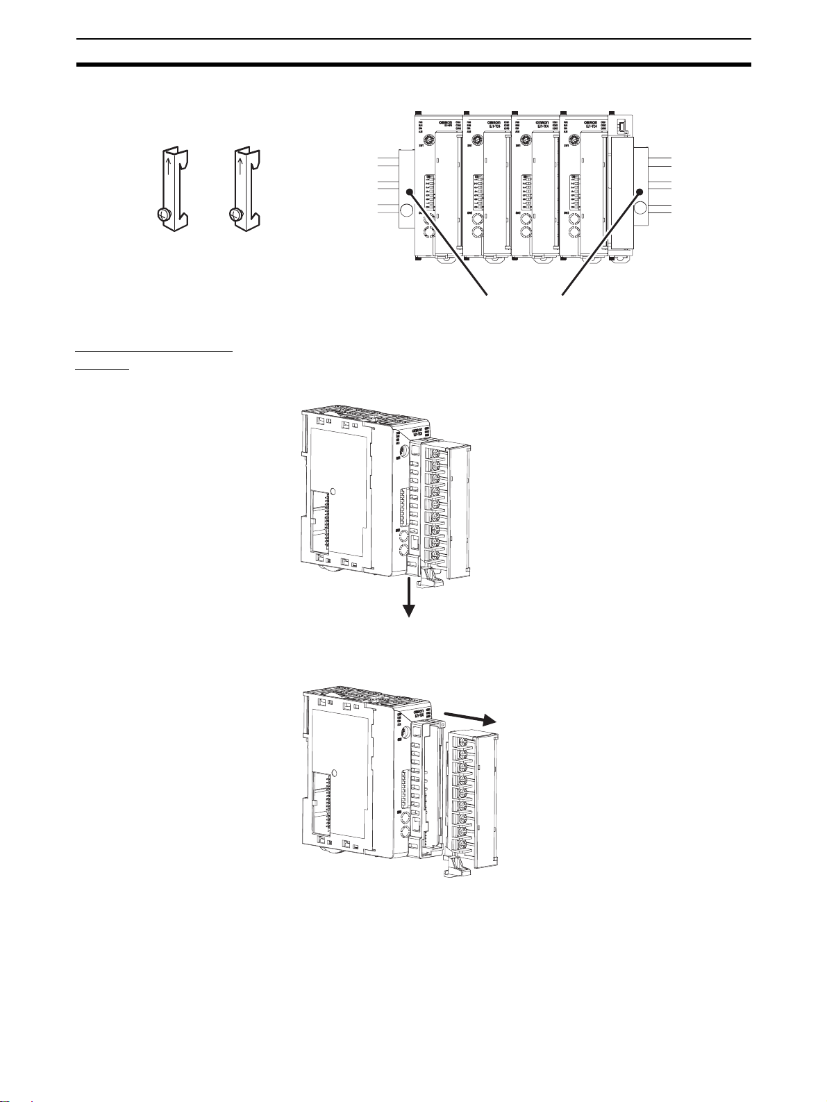
Installation Section 2-1
2-1-2 Mounting and Removing Terminal Blocks
Connecting Units
1,2,3... 1. Align the connectors and connect the Units to each other.
Note Connect the EDU on the right end of the EJ1G and the HFU on the left end.
2. Slide the yellow sliders on the to p and bott om of the U nits until they click
into place.
Slider Lock
3. Attach the cover seal to the connector on the Uni t on the left end of the
EJ1G.
Cover seal
13
Page 35

Installation Section 2-1
Mounting to DIN Rail • Mount the EJ1G to DIN Rail.
• Use screws to secure the DIN Rail in at least 3 locations.
DIN Rail: PFP-50N (50 cm) or PFP-100N (100 cm)
• Install the DIN Rail vertically to the ground.
Vertical: OK
Horizontal: NG
Installation Method Pull down the hooks on the bottoms of the Units, and then catch the hooks on
the tops of the Un its onto th e DIN Rail and pr ess the U nits onto the DIN Rail
until they lock into place.
2. Catch the upper hooks onto the DIN Rail.
3. Press in on the Units.
1. Pull down the hooks.
4. Make sure the Units are
locked into place.
Removal Method Pull down on the hooks with a flat-blade screwdriver and lift up on the Units.
Flat-blade screwdriver
(unit: mm)
14
Flat-blade screwdriver
0. 4
2. 5
Page 36
Installation Section 2-1
End Plate Installation Always mount an End Plate on each side of the EJ1G.
PFP-M End Plates (2)
Removing Terminal
Blocks
1,2,3... 1. Pull down the terminal block lever.
Pull down the lever.
2. Pull off the terminal block.
PFP-M
Pull off the terminal block.
Note M3 screw and screw-less terminal blocks cannot be exchanged. U se the typ e
of terminal block supplied with the TC Unit.
15
Page 37

Wiring Terminals Section 2-2
2-2 Wiring Terminals
2-2-1 Ter minal Arrangement
TC4
Pulse voltage outputs
OUT2
OUT1
+
mA
−
V
+
+
mA
−
V
+
Analog inputs
A
B
A
B
B
Platinum
resistance
thermometer
inputs
• Terminals A10 and B10 are not used on models with screw-less clamp terminals.
Do not connect anything to these terminals.
• A G3ZA connector is located on the bottom of the Unit.
• When wiring voltage inputs, be sure to wire the correct terminals. Incorrect wiring
may cause the EJ1G to fail.
12 VDC
12 VDC
CH2
CH1
Thermocouple inputs
Infrared thermosensor
B1
+
B2
+
B3
−
A1
A2
A3
B4
B
B5
−
B6
+
A4
A5
A6
B7
−
B8
+
B9
A7
A8
A9
12 VDC
+
+
12 VDC
−
CH4
−
+
CH3
−
+
OUT4
OUT3
A
B
B
A
B
B
+
mA
−
V
+
+
mA
−
V
+
16
Page 38

Wiring Terminals Section 2-2
TC2
Pulse voltage outputs
OUT2
OUT1
A
B
B
mA
+
−
V
+
mA
−
−
V
A
B
B
+
Analog inputs Platinum
resistance
thermometer
inputs
• Terminals A10 and B10 are not used on models with screw-less clamp terminals.
Do not connect anything to these terminals.
• A G3ZA connector is located on the bottom of the Unit.
• When wiring voltage inputs, be sure to wire the correct terminals. Incorrect wiring
may cause the EJ1G to fail.
+
DC12V
+
DC12V
−
CH2
−
+
CH1
−
+
Thermocouple
inputs
Infrared
thermosensors
B1
B2
B3
B4
B5
B6
B7
B8
B9
COM
A1
A2
A3
A4
A5
A6
A7
A8
A9
OUT4
OUT3
DO NOT USE
CT2
CT1
HFU
Port C
SUB4
SUB3
SUB2
SUB1
RDB (+)
RDA (−)
RS-422 RS-485
B (+)
A (−)
DO NOT USE
B1
B2
B3
B4
B5
B6
B7
B8
B9
COM
COM
EV4
A1
EV3
A2
A3
EV2
A4
EV1
A5
A6
Contact input
A7
A8
A9
SD
RD
SG
RS-232C RS-422
+
+
−
+
+
−
Non-contact input
SDB (+)
SDA (−)
DO NOT USE
• Terminals A10 and B10 are not used on models with screw-less clamp terminals.
Do not connect anything to these terminals.
17
Page 39
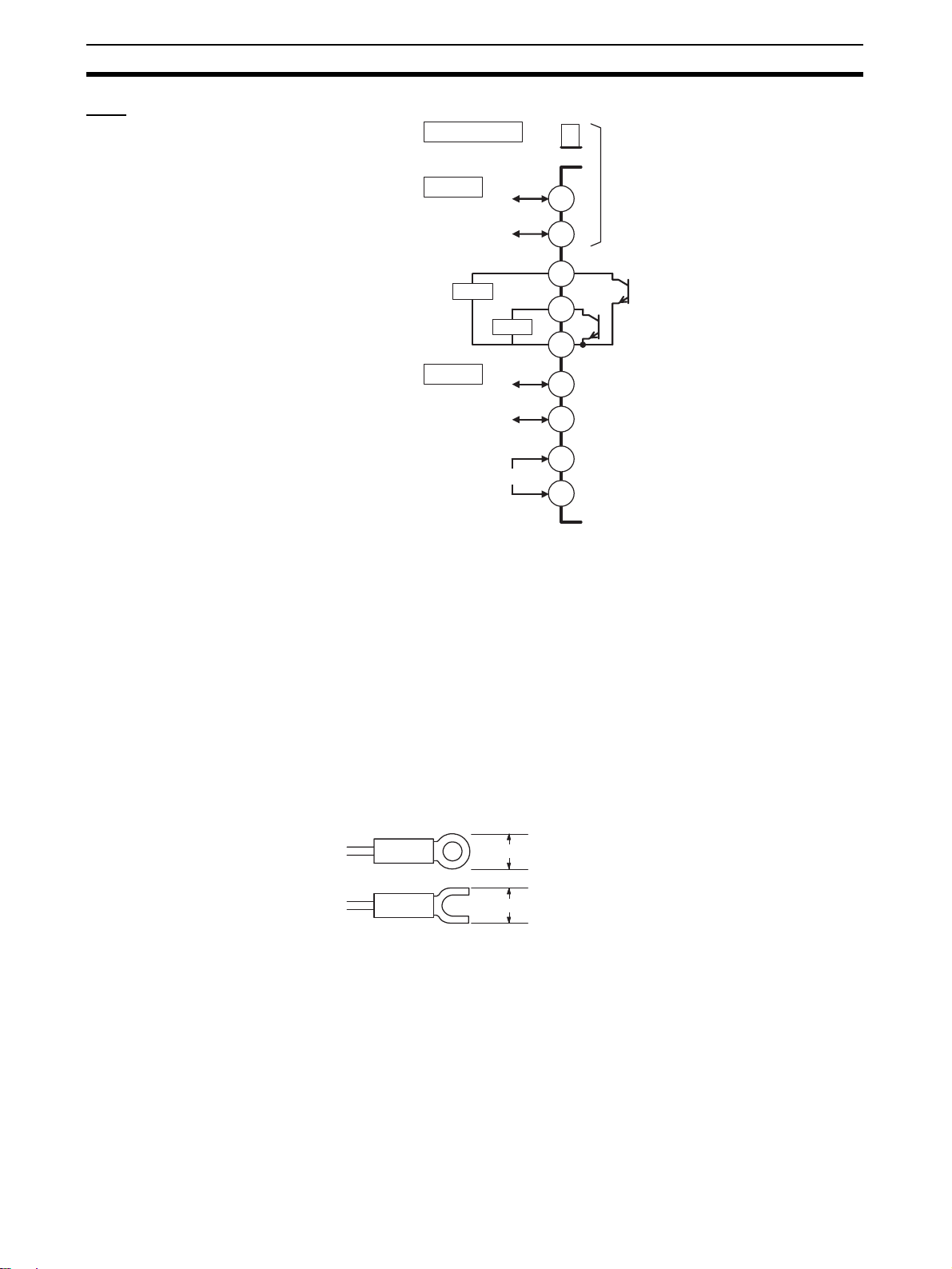
Wiring Terminals Section 2-2
EDU
Port A connector
2-2-2 Wiring Precautions
• Separate input leads and power lines to protect the EJ1G from external
noise.
• Use AWG22 (cross-sectional area: 0.326 mm
tional area: 2.081 mm
(cross-sectional area: 0.081 mm
1.309 mm
• Use crimp terminals when wiring the terminals.
• Tighten the terminal screws to a torque of 0.40 to 0.56 N·m.
• Up to two wires of the same size and same type or two crimp terminals
can be inserted into a single terminal.
• Use the following types of crimp terminals for M3 screws.
Port A
SUB2
Port B
Input power supply
2
) for all other cables. The stripping length is 6 to 8 mm.
B (+)
RS-485
SUB1
B (+)
RS-485
24 VDC
2
) twisted-pair cable for power supply and AWG28
A (−)
A (−)
1
2
3
4
5
6
7
+
8
−
9
These two ports cannot be
used at the same time.
COM
2
) to AWG14 (cross-sec-
2
) to AWG16 (cross-sectional area:
18
5.8 mm max.
5.8 mm max.
Page 40
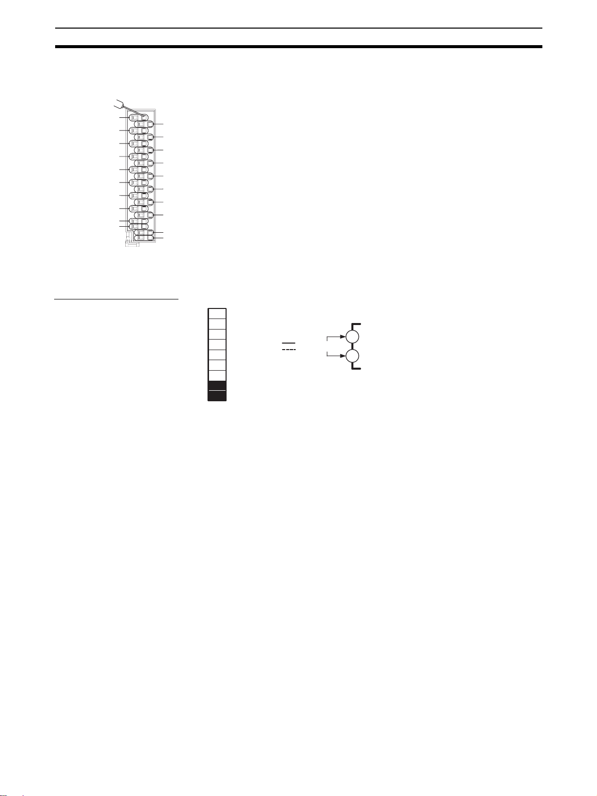
Wiring Terminals Section 2-2
0
Wiring Procedure for
Screw-Less Clamp
Terminals
There are two holes for each ter minal. The h ole on the ri ght is the operating
hole; the hole on the left is the wire hole.
Insert a flat-blade s crewdriver with a width of 2.5 mm into the operating hole
and then insert the wiring into the wire hole.
B1
B2
B3
B4
B5
B6
B7
B8
B9
B10
A1
A1
A2
A3
A4
A5
A6
A7
A8
A9
The wire will be clamped when the screwdriver is removed.
Use crimp ter minals for wiring that matc h the cross-sectio nal area of the
wiring material.
We recommend the following crimp terminals:
Weidmuller H-sleeve Series
2-2-3 Wiring
Power Supply Voltage Connect the power supply to EDU terminals 8 and 9 as shown below.
1
2
3
4
5
6
7
8
9
EDU
24-VDC
input power
supply
+
−
8
9
• If reinforced insulation is required, c onnec t the input an d output terminals
to a device without any exposed current-carrying parts or to a device with
standard insulation suitable for the maximum operating voltage of the
power supply I/O section.
• Conforming to Safety Standards
The power supply terminals must be supplied from a SELV, limited-current
source. A SELV (separated extra-low voltage) source is a power supply
having double or reinforced insulatio n between the prima ry and the secondary circu its and h aving an output voltage of 30 V r.m.s. max. and 42.4
V peak max. or 60 VDC max.
Recommended power supply : S8VM Se ries or S8VS Se ries (both manufactured by OMRON)
Note Select a power supply that suits the operating environment.
• To comply with the st andards for nois e ter minal voltage for class A i n EN
61326, install a noise fil ter (Densei Lamb da MXB-1206-3 3 or the equivalent) to the DC line as close as possible to the EJ1G.
19
Page 41

Wiring Terminals Section 2-2
Inputs Connect inputs according to the input type as shown below.
B1
B2
B3
B4
B5
B6
B7
B8
B9
B1
B2
B3
B4
B5
B6
B7
B8
B9
TC4
TC2
A1
A2
A3
A4
A5
A6
A7
A8
A9
A1
A2
A3
A4
A5
A6
A7
A8
A9
CH2
CH1
Thermocouple inputs
Infrared thermosensor
TC2
−
+
−
+
B4
B5
B6
B7
B8
B9
TC4
A4
A5
A6
A7
A8
A9
−
+
CH4
−
+
CH3
TC4
TC2
A
B4
B
B5
B
B6
CH2
A
B7
B
B8
B
B9
CH1
Platinum resistance
thermometer inputs
A4
A5
A6
A7
A8
A9
A
B
B
CH4
A
B
B
CH3
mA
V
CH2
mA
V
CH1
TC2
+
B4
−
B5
+
B6
+
B7
−
B8
+
B9
Analog inputs
TC4
A4
A5
A6
A7
A8
A9
+
−
+
CH4
+
−
+
CH3
mA
V
mA
V
Control Outputs Terminals B1 to B3 and A1 to A3 on the TC4/TC2 are for control outputs.
B1
A1
B2
B3
B4
B5
B6
B7
B8
B9
B1
B2
B3
B4
B5
B6
B7
B8
B9
TC4
TC2
A2
A3
A4
A5
A6
A7
A8
A9
A1
A2
A3
A4
A5
A6
A7
A8
A9
OUT2 12 VDC
OUT1
OUT2 12 VDC
OUT1
B1
B2
B3
B1
B2
B3
+
+
12 VDC
−
+
+
12 VDC
−
TC4
TC2
+
+
12 VDC
−
COM
A1
OUT412 VDC
A2
OUT3
A3
A1
OUT4
A2
OUT3
A3
20
Output type Specifications
Pulse voltage
outputs
Transistor
outputs
Output voltage: 12 VDC ±15% (PNP)
Max. load current: 21 mA, with short circuit protection circuit.
Max. applicable voltage: 30 VDC
Max. load current: 100 mA
Residual voltage: 1.5 V max., Leakage current: 0.4 mA max.
Page 42

Wiring Terminals Section 2-2
Auxiliary Outputs Auxiliary outputs are sent from pins B1 to B6 with the HFU, and from pins 3 to
5 with the EDU.
B1
A1
B2
A2
B3
A3
B4
A4
B5
B6
B7
B8
B9
HFU
1
2
3
4
5
6
7
8
9
EDU
A5
A6
A7
A8
A9
SUB4
SUB2
SUB3
SUB1
B1
B2
B3
B4
B5
B6
HFU
COM
COM
SUB2
SUB1
3
4
5
COM
EDU
Output type Specifications
Transistor
outputs
Max. operating voltage: 30 VDC
Max. load current: 50 mA
Residual voltage: 1.5 V max., leakage current: 0.4 mA max.
CT Inputs When the heater burnout (HB ) or heater sh or t (HS) ala rm is to be used, con-
nect a Current Transform er (CT) across t er minals A8 and A9 o r ter mina ls A7
and A9 (no polarity) on the TC2.
B1
A1
B2
A2
B3
A3
B4
A4
B5
A5
B6
A6
B7
A7
B8
A8
B9
A9
TC2
• Use a E54-CT1 or E54-CT3 Current Transformer.
A7
CT2
A8
CT1
A9
21
Page 43

Wiring Terminals Section 2-2
Event Inputs Connect event inputs across terminals A4 and A6 for the HFU.
B1
A1
B2
A2
B3
B4
B5
B6
B7
B8
B9
HFU
A3
A4
A5
A6
A7
A8
A9
A1
EV4
A2
EV3
A3
A4
EV2
A5
EV1
A6
A1
A2
A3
A4
A5
A6
+
+
−
+
+
−
EV4
EV3
EV2
EV1
Contact inputs
Non-contact inputs
• The inflow current is approximately 4 mA.
• Use event inputs under the following conditions:
Contact inputs ON: 1 kΩ max., OFF: 100 kΩ min.
Non-contact
inputs
ON: Residual voltage: 1.5 V max., OFF: Leakage current: 0.1 mA
max.
Communications • For communications with the host, connect communications across termi-
nals B7 and B8 or ter minals A7 to A9 on the HFU or connect ac ross terminals 1 and 2 on the EDU.
B1
A1
B2
A2
B3
A3
B4
A4
B5
A5
B6
A6
B7
A7
B8
A8
B9
A9
HFU
1
2
3
4
5
6
7
8
9
EDU EDU
RDB (+)
RDA (−)
B (+)
A (−)
B (+)
A (−)
Port A communications
B7
B8
RS-485 RS-232C
Port C communications
1
2
RS-485
HFU
A7
A8
A9
SD
RD
SG
SDB (+)
SDA (−)
DO NOT USE
RS-422RS-422
22
Note • If there are problems with communications noise performance when using
the port A connector, connect 110 to 125
Ω of terminating resistance
across terminals 1 and 2 of port A on the EDU.
• Specify both ends of the transmission pa th, including the hos t computer,
as end nodes (i.e., connect term inat or s to both end) . The min imum terminating resistance is 54
Ω.
Page 44
Wiring Terminals Section 2-2
r
■ Connection Example
Host Shield
R
EJ1G EDU
EJ1G EDU
• The RS-485 connection can be either 1:1 or 1:N. RS-232C connections
can only be 1:1. A maximum of 32 Units (includ ing the ho st) can be connected in 1:N systems. The maximum total cable length is 500 m. Use
AWG28 (cross-sectional area: 0.081 mm
area: 1.309 mm
+
−
FG
1
B (+)
2
A (−)
1
B (+)
2
A (−)
2
) shielded twisted-pair cable.
RS-485
Terminator
110 to 125 Ω (1/2 W)
R
2
) to AWG16 (cross-sectional
Cross-sectional area of conducto
AWG28: 0.081 mm2
AWG16: 1.309 mm
2
23
Page 45

Wiring Terminals Section 2-2
Connecting to the
G3ZA Multi-channel
Power Controller
CN1
CN1
Connect the G3ZA
Connecting Cable to the
CN1 connector on the
bottom of the TC Unit.
1
2
B (+)
A (−)
READY
SD/RD
SW1
OCC
SW2
ERROR
Set SW2 to 3 (57.6 kbps).
Connect the black line with a white stripe
to terminal 7 on the G3ZA and the black
line with no stripe to terminal 8.
EJ1C-CBLA050 (order separately) (cable
length: 5 m)
Use a JST Mfg. Co. Ltd. PA connector.
Housings
Model: PAP-02V-S
Crimp Terminals
Model: SPHD-001T-P0.5
Use an EJ1C-CBLA050 Cable (manufactured by OMRON).
TC4/TC2
24
Page 46

Using Tool Ports Section 2-3
w
2-3 Using Tool Ports
Tool ports are used to make EJ1G settings using the EST2-2C-MV3 CXThermo Support Software.
The E58-CIFQ1 USB-Seri al Conversion Cable is required t o make the connection.
2-3-1 Procedure
1,2,3... 1. Turn ON the power supply to the EJ1G.
Note Do not connect the E58-CIFQ1 while the power supply to the EJ1G
is OFF. If the Ca ble is connected when the power to the EJ 1G is
OFF, power will be supplie d from the co mputer and im pose a loa d
on the internal circuits of the EJ1G.
2. Connect the Cable.
Connect the computer's US B port with the port A conne ctor on the EJ 1G
using the Cable.
Port A connector
E58-CIFQ1
Computer
EDU Front Vie
3. Install the driver.
A driver must be installed to use the Cable.
• When the Cable is connecte d with th e com puter, the OS will detect a
new device.
Follow the installation wizard instructions and install the driver.
Note For details on instal lation methods, refer to the user's manual for
the E58-CIFQ1 USB-Serial Conversion Cable.
4. Make the communications port settings.
The USB-Serial Conversion Cable is used to commun icate with th e COM
port of the computer.
Set the communicatio ns port (COM por t) number to be u sed for the CXThermo software to the COM port assigned to the Cable.
25
Page 47

Unit Configuration Examples Section 2-4
2-4 Unit Configuration Examples
EJ1G-HFU
EJ1G-TC4
or
EJ1G-TC2
G3ZAG3ZA G3ZA
EJ1C-EDU
PLC
Port A (connector): USB connection
can be made using the E58-CIFQ1
(sold separately).
Port B is used for distributed placement.
CX-Thermo for setting
PC
26
Page 48

Unit Configuration Examples Section 2-4
2-4-1 Connection Precautions
Restrictions on the Number of Units that Can Be Connected
• Unit numbers 0 to 31 can be used for EJ1G-HFU and EJ1G-TC4/TC2
Units.
• Up to 16 Units, including the HFU, can be connected side by side. (EDU
Units are not counted in the number of Units that can be connected.)
Precautions When Using
an HFU
Note When using distributed positioning, turn ON power to the distributed Units first
• One HFU can control up to 16 TC4/TC2 Units.
• The unit numbers of the TC4/TC2 Units can be set to between 0 and 31.
• To c onnect 16 TC4/TC2 Un its, Communications Cables must be us ed to
distribute Unit positioning because the maximum number of Units that can
be connected horizontally will be exceeded.
• When using Communicatio ns Cables to dis tribute TC 4/TC2 Un it positi oning, connect the cables to port B on the End Units.
• If distributed positioning is used for an EJ1G, power must be supplied
separately to the terminal block on the End Units.
or turn ON power to the HFU and distributed Units simultaneously. Even if this
is done, there may still be problems wi th the s tar tup timi ng depend ing on th e
EJ1G configuration and power supply capacity. If problems occur at star tup,
increase the delay between turning ON the power to t he d istributed Units and
the HFU.
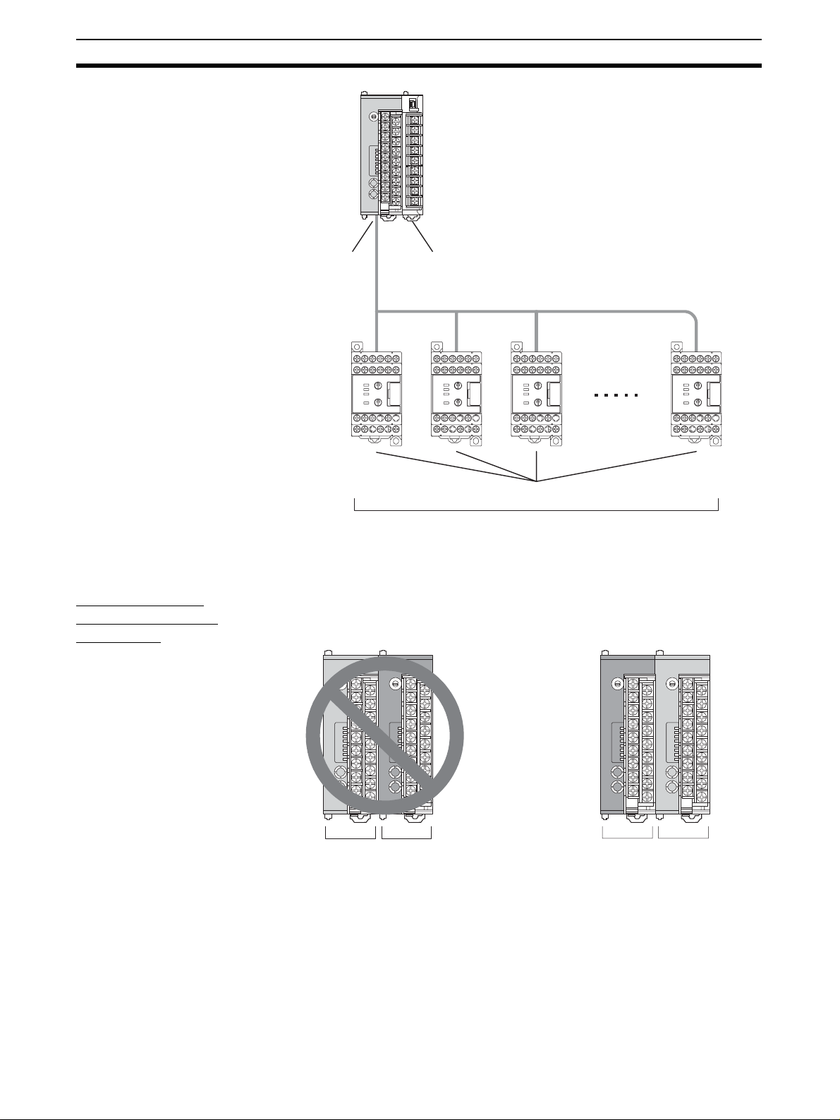
One HFU can manage up to 16 TC Units (4 channels × 16 Units = 64 channels)
EDU Units are not included in the number of Units that can be managed.
Turn ON
pin 8 on
SW2.
EJ1G-HFU
Up to 16 Units can be connected side by side.
EDU Units are not counted in the number of Units that can be connected.
EJ1G-TC4
or
EJ1G-TC2
EJ1C-EDU
EJ1G-TC4
or
EJ1G-TC2
EJ1C-EDU
27
Page 49

Unit Configuration Examples Section 2-4
Maximum Number of
Connectable Units
The maximum number of Units that can be connec ted is some times limited to
16 or less, depending on the maximum number of channels per group and the
types of Basic Unit used. Refer to the following table for information on the
maximum number of connectable Units.
Maximum
number of
channels per
group
2 161616 8
3 10151612
4 8 16 16 16
5 615810
6 515812
7 414814
8 4 16 8 16
931449
10315410
11211411
12212412
13213413
14214414
15215415
16 2 16 4 16
171929
181929
19110210
20110210
21111211
22111211
23112212
24112212
25113213
26113213
27114214
28114214
29115215
30115215
31116216
32 1 16 2 16
Maximum
number of
groups
TC2 TC4
Maximum
number of
connectable
Units
Maximum
number of
groups
Maximum
number of
connectable
Units
28
Example: Performing 6-channel Gradient Temperature Control with TC2 Units
The maximum number of gro ups i s 5, and th e m ax imum numbe r of Uni ts tha t
can be connected is 15.
Page 50

Unit Configuration Examples Section 2-4
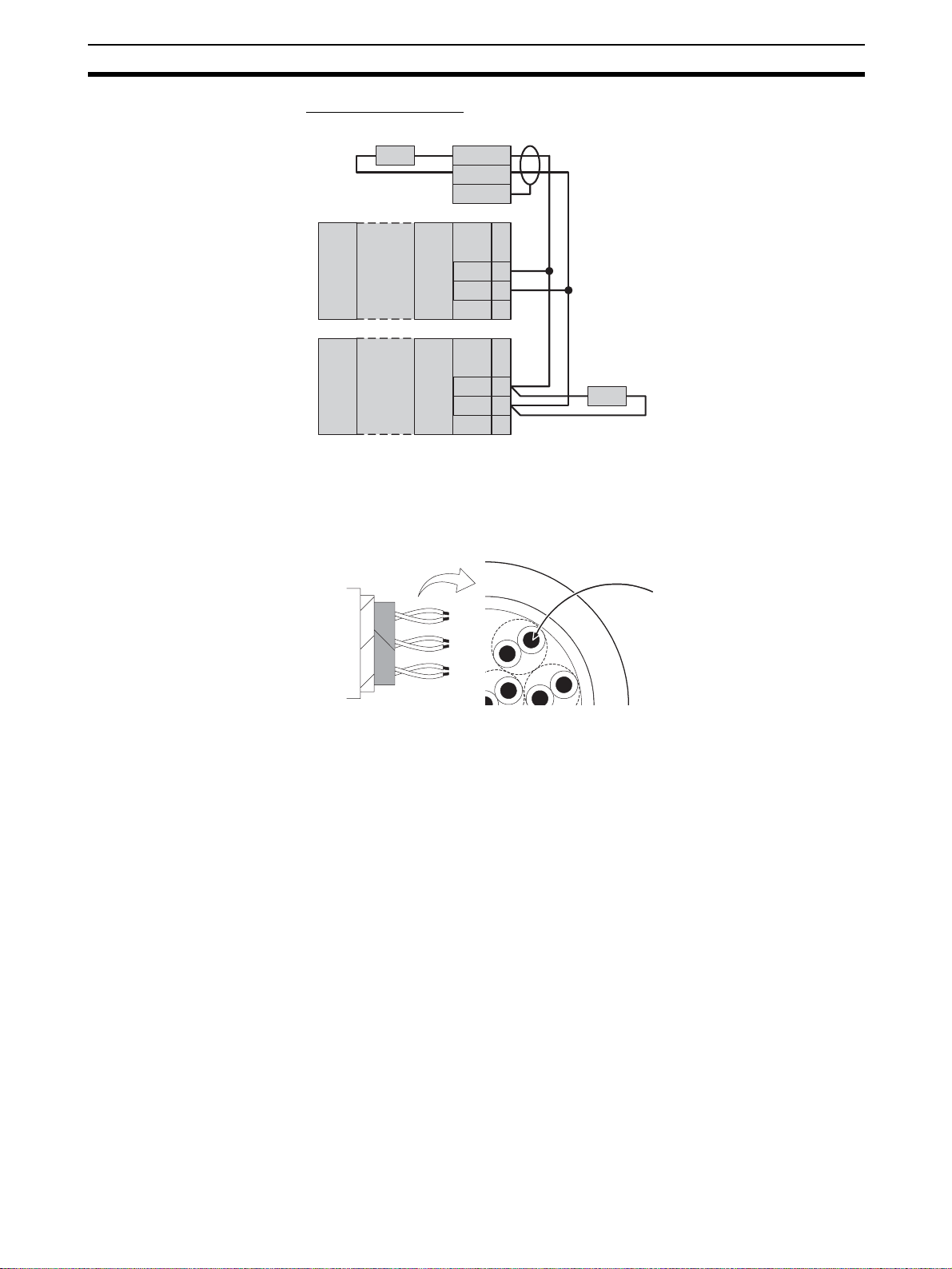
Wiring for Distributed
Placement
Group A
1
2
3
4
5
6
7
8
9
Terminator
110 to 125 Ω
+
(1/2 W)
−
Terminator
110 to 125 Ω
(1/2 W)
+
24 VDC
−
Note Wire the connections indicated with dotted lines when setti ngs for all EJ 1G
Connecting the G3ZA and
EJ1G
Note Either turn ON power to the G3ZA first, or turn O N power to the G3ZA and
Group B
1
2
3
4
5
6
7
8
9
Terminator
110 to 125 Ω
+
(1/2W)
−
Terminator
110 to 125 Ω (1/2 W)
+
24 VDC
−
RS-485
RS-485
Controllers are being made from one port A connector. If the connections indicated with dotted li nes are not wired, the setti ngs for group A can be made
only using the por t A connector for group A and the settings for group B can
be made only using the port A connector for group B.
• Up to 8 G3ZA Power Controllers can be connected to one TC4/TC2 Unit.
EJ1G simultaneously.
29
Page 51
Unit Configuration Examples Section 2-4
Restrictions on
Connections and
Placement
EJ1G-TC4
or
EJ1G-TC2
EJ1C-EDU
G3ZA
Up to 8 G3ZA Power Controllers can be
connected to one TC Unit.
• Always connect the HFU on the left side of the TC4/TC2 Units.
CorrectIncorrect
30
EJ1G-TC4
or
EJ1G-TC2
EJ1G-HFU EJ1G-TC4
EJ1G-HFU
or
EJ1G-TC2
Page 52

Unit Configuration Examples Section 2-4
• Do not connect an E DU d irec tly t o a n HFU. Always connect th e EDU to a
TC4/TC2.
Incorrect
EJ1G-HFU
EJ1C-EDU
Correct
EJ1G-HFU
EJ1G-TC4
or
EJ1G-TC2
EJ1C-EDU
31
Page 53

Unit Configuration Examples Section 2-4
32
Page 54

SECTION 3
Gradient Temperature Control Setup
This section describes how to set up and adjust gradient temperature control and how to change the SPs during operation.
3-1 Setup Procedure . . . . . . . . . . . . . . . . . . . . . . . . . . . . . . . . . . . . . . . . . . . . . . . 34
3-2 Adjusting Gradient Temperature Control . . . . . . . . . . . . . . . . . . . . . . . . . . . . 46
3-3 Changing SPs During Operation. . . . . . . . . . . . . . . . . . . . . . . . . . . . . . . . . . . 47
33
Page 55

Setup Procedure Section 3-1
(
)
3-1 Setup Procedure
Use the following procedure to perform gradient temperature control.
1. Select the models.
2. Set the Communications unit num bers.
3. Make the I/O settings.
4. Make the gradient group settings.
5. Arrange the Sensors.
6. Register the configuration.
7. Set decimal point position B.
8. Make the SP and alarm settings.
9. Perform tuning for gradient temperature control.
10. Start control.
11. Perform tuning for 2-PID control.
12. Check the heater burnout alarm status.
Example: Performing 3-channel Gradient Temperature Control
• Gradient temperature control is performed for 3 groups.
• Also, 2-PID control is performed for three chan nels in addition to gradien t
temperature control.
• Heater burnout is detected for all channels.
Upper heater
(2-PID control)
Lower heater
Gradient temperature control performed for three heaters
1. Select the models.
TC2 Basic Units are used because heater burnout detection is performed.
• Select TC2 Units to detect heater burnout.
• Select TC4 Units when not detecting heater burnout.
Note A mixture of TC2 and TC4 Units can be used.
Here, a total of 12 channels are required, so 6 TC2 Units are needed.
H
T
T
T
T
T
T
E
F
C
C
C
C
C
C
D
U
2
2
2
2
2
2
U
6 Units (x TC2 = 12 channels)
34
Page 56

Setup Procedure Section 3-1
Three-channel gradient contr ol for 3 groups + 3 chan nels of PID control =
12 channels
2. Set the Communications Unit numbers.
Set the Communications unit numbers as shown below.
0 1 2 3 4 5 6
H
T
T
T
T
T
T
E
F
C
C
C
C
C
C
D
U
2
2
2
2
2
2
U
Note (a) The Communications unit numbers can be set between 0 and 31.
Set a number in this range.
(b) When connecting to an OMRON PLC, set the HFU unit number
to between 0 and 7.
3. Make the I/O settings.
The I/O settings are made for each Basic Unit.
0 1 2 3 4 5 6
H
T
T
T
T
T
T
E
F
C
C
C
C
C
C
D
U
2
2
2
2
2
2
U
Set the I/O for each Basic Unit.
Communications Unit No.
The following table shows the input type and control per iod for each TC2
Unit in this example.
Parameter Communications Unit No.
Variable type Address Name 1 2 3 4 5 6
E0 (A0) 0100 Input Type - CH1 5 (K: −200 to 1300°C)
0200 Input Type - CH2 5 (K: −200 to 1300°C)
E1 (A1) 0101 Control Period 1 2 s
0201 Control Period 2 2 s
4. Make the gradient group settings.
The gradient group settings are made on the HFU.
0 1 2 3 4 5 6
H
T
T
T
T
T
T
E
F
C
C
C
C
C
C
D
U
2
2
2
2
2
2
U
35
Page 57

Setup Procedure Section 3-1
p
)
p
)
The heaters are first divided into groups and it is decided whether e ach
group will use gradient temperature control or 2-PID control. In this example, there are three groups of gradient temperature control for three channels and one group of 2-PID control for three channels. The groups are
divided as shown in the following diagram.
0 1 2 3 4 5 6
TC2
TC2 TC2 TC2 TC2 TC2
H
CH1
CH1
F
CH1 CH1 CH1 CH1
U
CH2 CH2 CH2 CH2 CH2
CH2
E
D
U
Group 1 (gradient)
Grou
2 (gradient
Group 3 (gradient)
Grou
4 (2-PID
The group settings are made with the following parameters.
Parameter Description
Number of Enabled
Groups
Initial Communications Unit No.
Initial Channel Sets the initial channel for the initial communications unit
Number of Enabled
Channels
Control Type Sets whether the g r ou p w ill p erform gradient temperature
Sets the total number of groups, consisting of those performing gradient temperature control and those performing 2-PID control.
Sets the communications unit number for the group’s initial channel.
number.
Sets the number of channels performing gradient temper-
ature control or 2-PID control.
control or 2-PID control.
Note (a) When the group settin gs are changed after temperature control
has been performed, the control-related parame ters are not initialized. To redo the group settings after co ntrol has been performed, be sure to initialize the setting parameters before
changing the group settings.
(b) The control operation cycle will get longer if there are a lot of
channels or groups performing gradient temperature control,
which may affect control performance. Refer to Characteristics on
page 171 for details.
36
Page 58

Setup Procedure Section 3-1
The following table shows the group settings for this example.
Variable
type
F1 (B1) 0000 Numbe r of enabled groups 4
Address Parameter Setting value
0100 Group 1 Initial Communica-
tions Unit No.
0101 Initial Channel 0
0102 Number of Enabled
Channels
0103 Control Type 0: Gradient tem-
0200 Group 2 Initial Communica-
tions Unit No.
0201 Initial channel 1
0202 Number of Enabled
Channels
0203 Control type 0: Gradient tem-
0300 Group 3 Initial Communica-
tions Unit No.
0301 Initial Channel 0
0302 Number of Enabled
Channels
0303 Control Type 0: Gradient tem-
0400 Group 4 Initial Communica-
tions Unit No.
0401 Initial Channel 1
0402 Number of Enabled
Channels
0403 Control Type 1: 2-PID control
1
3
perature control
2
3
perature control
4
3
perature control
5
3
The HFU handles all of the operations for gradient temperature control and
2-PID control. The maximum number of enabled channels that can be controlled is selected at the HFU from 4, 8, 16, or 32 channels, and that number of channels is allocated for the number of groups used.
In this example, the maximum number of enabled channels is three, so the
HFU allocates groups in units of four channels each. The HFU recognizes
the following channels for the Basic Unit.
37
Page 59

Setup Procedure Section 3-1
p
)
0 1 2 3 4 5 6
TC2
TC2 TC2 TC2 TC2 TC2
H
CH1
F
CH3 CH6 CH9
CH11 CH14
U
CH2
CH5 CH7
CH10 CH13 CH15
E
D
U
Group 1 (gradient)
Group 2 (gradient)
HFU channels Groups
11
2
3
4 Not usable
52
6
7
8 Not usable
93
10
11
12 Not usable
13 4
14
15
16 Not usable
Group 3 (gradient)
Grou
4 (2-PID control
Note (a) The HFU can control up to 64 ch annels, but when th e maximum
number of enabled channels is a number other than 4, 8, 16, or
32 channels, non-usable chann els r esult as shown in this example. This limits the number of controllable channels and connectable Units. Refer to Maximum Number of Conne ctable Units on
page 28 for details.
(b) If the maximum number of enabled chann els is changed in the
configuration, the numb er of channels allocated for each group
and the initial channel for each group may change.
5. Arrange the Sensors.
Arrange the sensors sequentially to maximize the control performance
within gradient temperature control groups.
38
Connection Example with Control Object Heaters in a Line
Good example Bad example
CH1 CH2 CH3 CH4 CH5
CH1 CH3 CH5 CH4 CH2
Page 60

Setup Procedure Section 3-1
Connection Example with Control Object Heaters in a Plane
Good example Bad example
CH7
CH6 CH1 CH2
CH5
CH4
CH8
CH3
CH9
CH3
CH7 CH9 CH8
CH1
CH4
CH5
CH6
The example used here results in the following sensor arrangement.
0 1 2 3 4 5 6
TC2
TC2 TC2 TC2 TC2 TC2
H
CH3
CH6 CH9
CH1
F
U
CH5 CH7
CH2
Heater block 1 Heater block 2 Heater block 3
CH13 CH14 CH15
CH1 CH2 CH3
CH5 CH6 CH7 CH9 CH10 CH11
Note: The connections for heater blocks 2 and 3 are omitted above.
CH10
CH11 CH14
CH13 CH15
E
D
U
Always short-circuit the input for any unused channels in the Basic Unit.
6. Register the configuration.
The configuration is registered in the HFU.
CH2
0 1 2 3 4 5 6
H
T
T
T
T
T
T
E
F
C
C
C
C
C
C
D
U
2
2
2
2
2
2
U
No configuration is registered when the product is shipped. Always register
the configuration. If the correct configuration is not registered or if the configuration is not correctly detected, the Basic Unit channels detected by the
HFU may be incorrect.
Use the following procedure to register the configuration.
a. Execute the following operation commands.
• Execute the operation command to set all channels to AUTO mode.
• Execute the operation command to set all channels to STOP mode.
b. Reset the EJ1G using one of the following methods.
• Execute a software reset with an operating command to the HFU.
Note All connected Units will be reset when the HFU is reset.
• Cycle the EJ1G power supply.
c. Check the following after restarting.
39
Page 61

Setup Procedure Section 3-1
• Read the Configuration Error A Status and check that there are no errors.
• Read the Device B Status and check that bit 12 (Configuration Registered) is OFF.
d. Use the operation com man d t o execute registration of Uni t c on fig ura-
tion.
e. Use the method ou tlined in step b) above to reset the EJ1G syste m
then check the following.
• Read Configuration Error A Status and check that there are no errors.
• Read the Device B Status and check that bit 12 (Configuration Registered) is ON.
• Check that the COM2 indicator is flashing for all Units.
Note Refer to SECTION 7 Errors and Error Processing to determine the
cause of any errors that occ ur dur ing when performing the procedure outlined above.
7. Set decimal point position B.
Decimal point position B is set for the HFU.
0 1 2 3 4 5 6
H
T
T
T
T
T
T
E
F
C
C
C
C
C
C
D
U
2
2
2
2
2
2
U
The decimal point pos ition for the PV is set us ing the Decima l Point Position B parameter. Set the same decimal point positi on as was set for the
TC2 Unit or TC4 Unit.
Decimal point position B must be set because it is u sed as the decimal
point position for the SP and alarm values.
In this example, the input type is set to 5 (Thermocouple (K):
−200 to
1,300) so the decimal point position must be set to 0.
Variable type Address Parameter Setting value
E0 (A0) 0000 Decimal Point Position B 0
Note The input type ca n be set separately for each channe l, but if different input
types are set, input type s with the same decimal point position. Temperature
control will not be executed correctly if different decim al point input types are
used.
8. Make the SP and alarm settings.
The SP and alarm settings are made for the HFU.
40
0 1 2 3 4 5 6
TC2 TC2 TC2 TC2 TC2
TC2
H
CH3
CH1
F
CH6 CH9
CH11 CH14
U
CH2
CH5 CH7
CH10 CH13 CH15
E
D
U
Page 62

Setup Procedure Section 3-1
The SP and alar m settings are made for the channels allocated in the
group settings. SP and alarm settings made for unusable channels will not
be enabled.
The following table shows the Set Point, Alarm Value 1, and Heater Burnout Detection settings for each channel for this example.
Variable
type
D0 (90) 0100 Bank 0 Set Point - CH1 200
Address Parameter Setting
value
0200 Bank 0 Set Point - CH2 200
0300 Bank 0 Set Point - CH3 200
0500 Bank 0 Set Point - CH5 200
0600 Bank 0 Set Point - CH6 200
0700 Bank 0 Set Point - CH7 200
010D Bank 0 Alarm Value - CH1 230
020D Bank 0 Alarm Value - CH2 230
030D Bank 0 Alarm Value - CH3 230
050D Bank 0 Alarm Value - CH5 230
060D Bank 0 Alarm Value - CH6 230
070D Bank 0 Alarm Value - CH7 230
Group 1
Group 2
Group 1
Group 2
D6 (96) 0100 Heater Burnout Detection - CH1 5.0 A
0200 Heater Burnout Detection - CH2 5.0 A
0300
0500 Heater Burnout Detection - CH5 5.0 A
0600 Heater Burnout Detection - CH6 5.0 A
0700
Heater Burnout Detection - CH3 5.0 A
Heater Burnout Detection - CH7 5.0 A
Group 1
Group 2
9. Perform tuning for gradient temperature control.
Tuning for gradient temperature control is cal led gradient tu ning ( GT). GT
is executed and stopped for the HFU.
0 1 2 3 4 5 6
TC2 TC2 TC2 TC2 TC2
TC2
H
CH3
CH1
F
CH6 CH9
CH11 CH14
U
CH2
CH5 CH7
CH10 CH13 CH15
E
D
U
GT is executed when all groups are in STOP and AUTO modes. GT can
also be executed for individual groups.
a. Check that all groups are in STOP and AUTO modes.
Read the channel status of the initial channel for each group and check
that bit 0 (RUN/STOP) is ON (STOP) and that bit 1 (AUTO/MANUAL)
is OFF (AUTO).
If any group does not satisfy these conditions, execute operation com-
41
Page 63
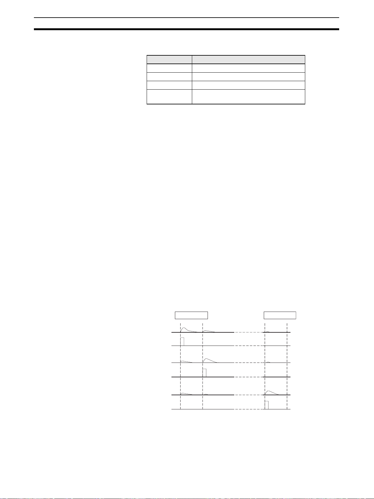
Setup Procedure Section 3-1
mands for the initial channel in the gro up an d se t to S TOP and AUTO
modes. Groups using 2-PID control also need to be in STOP mode.
Group Channel status
1 Check the status of channel 1.
2 Check the status of channel 5.
3 Check the status of channel 9.
4 Uses 2-PID control and, therefore, does not
b. Read the PV for all channels in groups for which GT is to be executed
and wait for all values to stabilize.
Note Correct tuning results will not be obtained if GT is started before the
PV stabilize.
c. GT is executed by executing an operating command for the initial
channel in the group for which GT is to be executed.
Channel status bit 2 (GT Execute/Cancel) is ON during GT.
Example: Executing Gradient Tuning for Group 3
An operating command is executed for channel 9 to execute GT.
Note Execute an opera ting c omm and for the initial channel in the group
to cancel GT if an error occurs during GT execution.
Note If any of the following conditions occur, GT will stop and channel
status bit 12 (GT Error) wil l turn ON for the initial channel in the
group. In such cases, remove the cause of the erro r and execute
GT again.
• If an input error has occurred.
• If the PV for the channel being output exceeds the SP.
Control may not be possible if the SP is too low, the output remains
ON, or the response speed of the control target is too fast.
During GT , the outputs in the group turn ON and OFF in order and the control target characteristics are measured. The following diagram shows the
actual operation.
need to be checked.
42
Example: GT for a 3-channel Configuration
GT started GT finished
CH1 temperature
CH1 output
CH2 temperature
CH2 output
CH3 temperature
CH3 output
d. Wait until the GT Execute/Cancel bit turns OFF.
GT is completed when this bit turns OFF. Read the PID for each chan-
Page 64

Setup Procedure Section 3-1
nel in the group and check that the values are refreshed.
Group 1 CH1 P=@@, I=@@, D=@@
CH2 P=@@, I=@@, D=@@
CH3 P=@@, I=@@, D=@@
Group 2 CH5 P=@@, I=@@, D=@@
Note An error will occur if a mix ture of gradient temperature con trol an d 2- P ID c on-
trol is used and GT or AT is executed for all channels. Execute GT or AT for
individual groups if a mixture of gradient temperature and 2-PID control is
used.
10. Start control.
Control is started and canceled for the HFU.
0 1 2 3 4 5 6
TC2 TC2 TC2 TC2 TC2
TC2
H
CH3
CH1
F
CH6 CH9 CH11
CH14
U
CH2
CH5 CH7
CH10 CH13 CH15
E
D
U
To start con trol for gradient tempera ture cont rol groups, fir st read t he status of the initial channel in the groups and check that bit 13 (GTC Error) is
OFF (No error) then execute a RUN operation command.
Note Gradient Temperature Control (GTC) Errors
If the power is interrupted immediately after GT has been completed or while downloading the HFU parameters using the Suppor t
Software, the internal parameters for GTC will not be refreshed correctly and control may not be able to be started. Use one of the following methods if this error occurs.
• Re-execute GT.
• Download the parameters again and reset.
• Initialize the setting values and reset.
Example1 : Starting Control for Group 2 (Gradient)
Execute a RUN operation command for channel 5.
Example 2: Starting Control for the Initial Channel in Group 4 (2-PID
Control)
Execute a RUN operation command for channel 13.
Example 3: Starting Control for All Groups
Execute a RUN command with all channels specified.
Note A RUN command can be executed even for a mixture of gradient
temperature and 2-PID control.
11. Perform Tuning for 2-PID Control.
Tuning for 2-PID control is called autotuning (AT). AT is executed and canceled for the HFU.
43
Page 65

Setup Procedure Section 3-1
0 1 2 3 4 5 6
TC2
TC2 TC2 TC2 TC2 TC2
H
CH3
CH6 CH9
CH1
F
CH11 CH14
U
CH2
CH5 CH7
CH10 CH13 CH15
AT is executed when set to RUN and A UT O modes. AT can also be executed for individual channels in a group.
a. Check that the channels for which AT is to be ex ecuted are in RUN and
AUTO modes.
Read the status o f the channels for which AT is to be executed and
check that bit 0 (RUN/STOP) is OFF (RUN) and bit 1 (AUTO/MANUAL)
is OFF (AUTO).
If these conditions are not met by a channel, execute operation commands for that channel and set to RUN and AUTO modes.
b. Execute an operation command to execute AT for the desired channel.
40% AT Execute and 100% AT Execute options are available. Refer to
page 78 for information on the operation differences between the two.
Channel status bit 2 (AT Execute/Cancel) will be ON during AT.
E
D
U
Example: Tuning Channel 14 in Group 4 (2-PID Control)
c. Execute an AT Execute operating command for channel 14.
Wait until the AT Execute/Cancel bit turns OFF.
AT has been completed when this bit turns OFF. Read the PID for the
corresponding channels and check that the values have been refreshed.
Note An err or wi ll oc cu r if a mixture of gradient t emp eratu re co ntr ol an d
2-PID control is used and GT or A T is executed for all channels. Execute GT or A T for individual groups if a mixture of gradient temperature and 2-PID control is used.
Note Execute AT for one channel at a time if optimum control perfor-
mance is required.
12. Check the Heater Burnout Alarm status.
The heater burno ut alarm (HB ) is checked by checking the status of th e
Channel Alarm Status b it. The heate r curren t is checked by checking the
status of the Heater Current Value Monitor bit.
44
Page 66

Setup Procedure Section 3-1
0 1 2 3 4 5 6
TC2
TC2 TC2 TC2 TC2 TC2
H
CH3
CH6 CH9
CH1
F
CH11 CH14
U
CH2
CH5 CH7
CH10 CH13 CH15
HB/HS alarm evaluation
Monitors the current and judgment results.
Variable
type
C4 (84) 0102 Channel Alarm Status - CH1
Address Parameter name
0202 Channel Alarm Status - CH2
0302 Channel Alarm Status - CH3
0502 Channel Alarm Status - CH5
0602 Channel Alarm Status - CH6
0702 Channel Alarm Status - CH7
E
D
U
Group 1
Group 2
C5 (85) 0100 Heater Current Value Monitor - CH1
0200 Heater Current Value Monitor - CH2
0300 Heater Current Value Monitor - CH3
0500 Heater Current Value Monitor - CH5
0600 Heater Current Value Monitor - CH6
0700 Heater Current Value Monitor - CH7
Group 1
Group 2
Heater burnout (HB) and SSR error (HS) alarms are detected by the Basic
Unit. Make any fine adjustments to hysteresis and latch settings at the Basic Unit.
45
Page 67
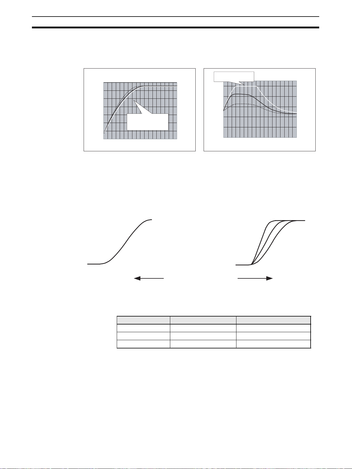
Adjusting Gradient Temperature Control Section 3-2
3-2 Adjusting Gradient Temperature Control
Sufficient temperature un iformity is some times diffic ult to achieve if the MV is
saturated when temperatures increas e.
160
140
120
100
Temperature
[°C]
80
60
40
20
0 50 100 150
Uniformity decreases
as the temperature
increases
Time [s]
Adjust the control balance coefficient if the temperature uniformi ty is insufficient and the MV for one of the channels becomes saturated. The control balance coefficient has the characteristics outlined below and must, therefore, be
adjusted to a value suitable for the system . The SP ca nnot be reac hed, however, if the control balance coefficient is too small. In such cases, return to the
default value of 0.8.
Uniformity increases but the
speed of the temperature rise drops
Saturated MV
100
80
60
MV
[%]
40
20
0
0 50 100 150
MVHot plate temperature
Time [s]
Temperature rise speed increases but
uniformity drops
Smaller
Control balance coefficient
Larger
Set the control balance coefficient for the initial channel for each group.
Example: Adjust the control balance coefficient for channel 5 if adjusting
group 2 when the following group settings apply.
Group Corresponding channels Control type
1 CH1 to CH4 Gradient temperature control
2 CH5 to CH8 Gradient temperature control
3 CH9 to CH12 2-PID control
46
Page 68

Changing SPs During Operation Section 3-3
e
3-3 Changing SPs During Operation
Several channels are grouped together for control whe n gradi ent tem perat ure
control is used. Ther efore, switch banks and cha nge the SP for all channels if
changing the SP during operation. Uniformity may be adversely affected if the
SP is not changed for all channels in the gradient temperature control groups.
CH1 SP
CH1 PV
CH1 and CH2 SP
CH2 SP
When the SPs are changed at different times
CH2 PV
When the SPs are changed at the same tim
The following example shows using bank switching to change SPs.
a. Change the SP for bank 1 during control using bank 0.
BANK CH1 SP CH2 SP CH3 SP
0 100 100 100 ← Control using bank 0
1 150 150 150 ← Change bank 1 SP
b. Switch to bank 1.
All SP for the group are refreshed when the bank is switched.
BANK CH1 SP CH2 SP CH3 SP
0 100 100 100
1 150 150 150 ← Switch to bank 1
When the initial channel of a gradient group is switched, the bank of channels allocated for that group will be switched. For 2-PID control groups, the
bank can be switched for individual channels in a group.
CH1 and CH2 PV
47
Page 69

Changing SPs During Operation Section 3-3
48
Page 70

Basic Units (TC4 and TC2) Functions
This section describes the functions of EJ1G Basic Units.
4-1 Setting Input Specifications . . . . . . . . . . . . . . . . . . . . . . . . . . . . . . . . . . . . . . 50
4-1-1 Input Type. . . . . . . . . . . . . . . . . . . . . . . . . . . . . . . . . . . . . . . . . . . . . 50
4-1-2 Temperature Inputs. . . . . . . . . . . . . . . . . . . . . . . . . . . . . . . . . . . . . . 51
4-1-3 Analog Inputs . . . . . . . . . . . . . . . . . . . . . . . . . . . . . . . . . . . . . . . . . . 51
4-1-4 Input Filter . . . . . . . . . . . . . . . . . . . . . . . . . . . . . . . . . . . . . . . . . . . . 52
4-2 Setting Output Specifications . . . . . . . . . . . . . . . . . . . . . . . . . . . . . . . . . . . . . 53
4-2-1 Control Output Method. . . . . . . . . . . . . . . . . . . . . . . . . . . . . . . . . . . 53
4-2-2 Alarm Outputs (TC2 Units Only). . . . . . . . . . . . . . . . . . . . . . . . . . . 53
4-3 Setting Control Specifications. . . . . . . . . . . . . . . . . . . . . . . . . . . . . . . . . . . . . 54
4-3-1 Manipulated Variable (MV) . . . . . . . . . . . . . . . . . . . . . . . . . . . . . . . 54
4-4 Detecting Current Errors. . . . . . . . . . . . . . . . . . . . . . . . . . . . . . . . . . . . . . . . . 55
4-5 Other Functions. . . . . . . . . . . . . . . . . . . . . . . . . . . . . . . . . . . . . . . . . . . . . . . . 56
4-5-1 Using G3ZA Multi-channel Power Controllers . . . . . . . . . . . . . . . . 56
SECTION 4
49
Page 71

Setting Input Specifications Section 4-1
4-1 Setting Input Specifications
4-1-1 Input Type
Set the input type to match the type of sensor being used.
Variable type Parameter name Setting range Default
E0/A0 Input Type (Channel) 0 to 29 5
Conditions for use No special conditions
List of Input Types
Input type Specifica-
Temperature
input
Analog
inputs
Platinum
resistance
thermometer
Thermocouple
inputs
ES1B
Infrared
Temperature
Sensor
Current
input
Voltage
input
tion
Pt100 0 −200 to 850 −300 to 1500
JPt100 3 −199.9 to 500.0 −199.9 to 900.0
K5−200 to 1300 −300 to 2300
J7−100 to 850 −100 to 1500
T9−200 to 400 −300 to 700
E 11 0 to 600 0 to 1100
L12−100 to 850 −100 to 1500
U13−200 to 400 −300 to 700
N15−200 to 1300 −300 to 2300
R 16 0 to 1700 0 to 3000
S 17 0 to 1700 0 to 3000
B 18 100 to 1800 300 to 3200
W 19 0 to 2300 0 to 4100
PLII 20 0 to 1300 0 to 2300
10 to 70°C 21 0 to 90 0 to 190
60 to 120°C 22 0 to 120 0 to 240
115 to 165°C 23 0 to 165 0 to 320
140 to 260°C 24 0 to 260 0 to 500
4 to 20 mA 25 Any one of the following ranges,
0 to 20 mA 26
1 to 5 V 27
0 to 5 V 28
0 to 10 V 29
Set value Setting range
(°C) (°F)
1 −199.9 to 500.0 −199.9 to 900.0
2 0.0 to 100.0 0.0 to 210.0
4 0.0 to 100.0 0.0 to 210.0
6 −20.0 to 500.0 0.0 to 900.0
8 −20.0 to 400.0 0.0 to 750.0
10 −199.9 to 400.0 −199.9 to 700.0
14 −199.9 to 400.0 −199.9 to 700.0
by scaling:
−1999 to 9999
−199.9 to 999.9
−19.99 to 99.99
−1.999 to 9.999
50
Page 72

Setting Input Specifications Section 4-1
4-1-2 Temperatur e Inputs
■ Temperature Unit
Either °C or °F can be selected.
Variable type Parameter name Setting range Default
E0/A0 Temperature Unit (Channel) 0: °C/1: °F 0
Conditions for use The input type must be set to temperature input.
■ Cold Junction Compensation Method
Specifies whether cold-j unction compensation is performed in the Temperature Controller or externally.
Enable external cold-junctio n compensation when using two thermocoupl es
to measure a temperature d ifference or using a external cold-junction c ompensator for even greater precision.
Variable type Parameter name Setting range Default
E0/A0 Cold Junction Compensation
Method (Common)
0: External /
1: Internal
1
4-1-3 Analog Inputs
Conditions for use
The input type must be set to thermocouple or infrared temperature sensor.
When an analog input is selected, scaling can be performed as needed by the
control application.
• The Scaling Upper Limit, Scaling Lower Limit, and Decimal Point Position
parameters are used for scaling. These parameters cannot be used when
a temperature input type is selected.
• The Scaling Upper Limit parameter sets the physical quantity to be
expressed by the upper limit value of input, and the Scal ing Lower Limit
parameter sets the p hysical quant ity to be expressed by the lower-limit
value of input. The Decimal Point Position parameter specifie s the number of digits below the decimal point.
• The following example shows scaling of an analog input (4 to 20 mA).
After scaling, the humid ity can be read directly. In this case, the decimal
point is set for 1 digit below the decimal point.
Display
(humidity)
Upper limit (95.0%)
Lower limit (10.0%)
4
20
Input (mA)
51
Page 73

Setting Input Specifications Section 4-1
r
Variable type Parameter name Setting range Default
E0/A0
(See note.)
Conditions for use The input type must be set to analog input.
This parameter can be set only when operation is stopped.
Always set the Scaling Upper Limit > Scaling Lower Limit.
If the Scaling Lower Limit > Scaling Upper Lim it, the larg er value will function
as the Scaling Upper Limit.
■ Setting Example
In this example, scaling is set to display 0 to 5 V as 10.0% to 95.0%.
Scaling Upper Limit = 950
Scaling Lower Limit = 100
Decimal Point Position = 1
Scaling Upper Limit (Channel) −1999 to 9999 1000
Scaling Lower Limit (Channel) −1999 to 9999 0
Decimal Point Position (Channel) 0: ****
1: ***.*
2: **.**
3: *.***
1
4-1-4 Input Filter
Sets the time constant of the digital input filter.
The following diagram shows the response of the d igital filter to a s tep-wise
input of amplitude A.
A
Variable type Parameter name Setting range Default
D5/95 Input Digital Filter (Channel) 0.0 to 999.9 Second 0.0
Conditions for use No special conditions
PV before passing through filter
PV after passing through filte
0.63 A
(Time
constant)
Input digital filter
Time
52
Page 74

Setting Output Specifications Section 4-2
4-2 Setting Output Specifications
4-2-1 Control Output Method
The time-proportional output method is used for the control output.
The MV determi nes the per centa ge of tim e that the output is ON dur ing e ach
control period.
100% 80% 60% 40% 20%
ON
OFF
Control
period
Note Control responsiveness improves as the control period is short-
ened, but if relays are being used for heater con trol, the rel ay lifetime will also be shortened so we recommend using a control
period of at least 20 seconds.
Variab le type Parameter name Setting range Default
E1/A1 Control Period 1 to 4 (I/O) 0 to 99 s 2
Conditions for use No special conditions.
Note If the parameter is set to 0, the period will be 0.5 s.
4-2-2 Alarm Outputs (TC2 Units Only)
Output 3 and output 4 from TC 2 Units are used to output alarm 1 for the
channel assigned to the TC2 Unit.
Example for the Following Groups
0 1 2 3 4 5 6
TC2
TC2 TC2 TC2 TC2 TC2
H
CH1
CH3
F
U
CH2
Group 1 (gradient)
Group 2 (gradient)
• If alarm 1 for channel 6 tur ns ON, output 3 from the TC2 Unit wit h communications unit number 3 turns ON.
• If alarm 1 for channel 10 tur ns ON, output 4 from the TC 2 Unit with communications unit number 4 turns ON.
CH6 CH9
CH5 CH7
CH11 CH14
CH10 CH13 CH15
Group 3 (gradient)
Group 4 (2-PID control)
E
D
U
53
Page 75

Setting Control Specifications Section 4-3
4-3 Setting Control Specifications
4-3-1 Manipulated Variable (MV)
■ MV at PV Error
The MV will be 0% when an internal communications error (between the HFU
and the TC4 or TC2 Unit) occurs.
54
Page 76

Detecting Current Errors Section 4-4
4-4 Detecting Current Errors
Set the Heater Burnout Hysteresis, Heater Burnout Latch, Heater Short Alarm
Hysteresis, and Heater Short Alarm Latch parameters in the TC2 or TC4
Units. Refer to 5-5 Detecting Current Errors for details.
55
Page 77

Other Functions Section 4-5
4-5 Other Functions
4-5-1 Using G3ZA Multi-channel Power Controllers
Initial Settings The following procedure is required in order to use a G3ZA. The G3ZA cannot
be used in the condition in which it is shipped.
1,2,3... 1. Connect the G3ZA to a Basic Unit. Up to eight G3ZA Units can be connect-
ed to one Basic Unit . If mo r e tha n ei ght Unit s are connected, a con f ig uration error will occur.
2. Turn ON pin 7 of SW2 on the Basic Unit, set SW2 on the G3ZA to 3
(57.6 kbps), and set SW1 on the G3ZA to between 0 and 7 (unit number).
The unit number of the G3ZA determines the MV sent from the Basic Unit.
For details, refer to Sending MVs to the G3ZA on page 57.
3. Tur n ON the power supply to the Basic Unit and execute a Register Unit
Configuration: Reset operation command. No G3 ZA Units are registe red
in the default Basic Unit settings.
4. Turn OFF the power sup ply to the Basic Unit and then turn ON the p ower
supply in the following order : G3ZA Units and then the Basi c Unit. When
the Basic Unit starts, it will automatically scan for connected G3ZA Units.
5. Check the Configuration Error A Status to see if any errors have occurred.
If there are no errors, execute a Register Unit Configuration: Regi ster operation command. The next time the Basic Unit is started, it will scan only
for the registered G3ZA Units, reducing the startup time.
Connection Example When the EJ1G s tar ts, it sca ns the co nnected G 3ZA Units and automa tically
assigns names G3ZA1, G3ZA2, etc., in order starting with the lowest unit
number.
Example: In this example, the G3ZA Units have been set to unit numbers 0, 1,
3, and 5.
The following diagram shows how the G3ZA Units are associated with the
EJ1G.
Unit 0 ⇒ G3ZA1
Unit 1 ⇒ G3ZA2
Unit 3 ⇒ G3ZA3
Unit 5 ⇒ G3ZA4
G3ZA
56
Unit No. 0 Unit No. 1 Unit No. 3 Unit No. 5
Page 78

Other Functions Section 4-5
Unit number Variable type Parameter name
0 DA/9A G3ZA1 - CH1 Slope
G3ZA1 - CH1 2 Slope
···
1 G3ZA2 - CH1 Slope
G3ZA2 - CH1 2 Slope
···
3 G3ZA3 - CH1 Slope
G3ZA3 - CH1 2 Slope
···
5 G3ZA4 - CH1 Slope
G3ZA4 - CH1 2 Slope
···
Settings The G3ZA settings are read and written through the Basic Unit.
The Basic Unit has addresses allocated in its variable area for use with the
G3ZA. The G3ZA set values can be read and written by reading and wr iting
that variable area. Refer to Parameter List on page 175 for details on the variable area for the G3ZA. Refer to the G3ZA Multi-channel Power Controller
User’s Manual (Cat. No. Z200) for details on the corresponding functio ns an d
settings.
Sending MVs to the
G3ZA
G3ZA Models with 4
Channels
■ Example
In this example, G3ZA settings are changed.
Unit No. 1
TC4 EDU Host device
Send the following command from the host device
to TC4 when setting the Channel 2 Heater
Burnout Detection Value to 10 A in the G3ZA with
unit number 1.
G3ZA G3ZA
[STX]0100001029A0219000001000A[ETX][BCC]
Unit No. 0 Unit No. 1
The G3ZA's unit number an d model deter mine which MVs are sent from th e
EJ1G to the G3ZA.
The EJ1G uses the G3ZA's unit number to determine whether to send heating
outputs or cooling outputs.
57
Page 79

Other Functions Section 4-5
• G3ZA Units with unit numbers 0 to 7
TC4 G3ZA
CH1 Control Output (Heating)
CH2 Control Output (Heating)
CH3 Control Output (Heating)
CH4 Control Output (Heating)
Note With a TC2, the Channel 3 and 4 MVs will be set to 0.0%.
Channel 1 MV
Channel 2 MV
Channel 3 MV
Channel 4 MV
G3ZA Models with 8
Channels
Note With a TC2, the Channel 3 to 8 MVs will be set to 0.0%.
MVs Output from the
G3ZA
!Caution If the MV is stored or calculated at the G3ZA and the G3ZA is turned ON
The following outputs will be sent whether the c ontrol method is s et to standard or heating/cooling control.
TC4 G3ZA
CH1 Control Output (Heating)
CH2 Control Output (Heating)
CH3 Control Output (Heating)
CH4 Control Output (Heating)
0.0%
0.0%
0.0%
0.0%
Channel 1 MV
Channel 2 MV
Channel 3 MV
Channel 4 MV
Channel 5 MV
Channel 6 MV
Channel 7 MV
Channel 8 MV
The outputs of predetermined channels are set in the G3ZA's MV, but any MV
can be output to multiple channels by setting the G3ZA's “Source Ch annel.”
Arithmetic operations can also be executed on each MV.
before the EJ1G, the controlled varia ble produced at th e G3ZA will be output
(the output may not be 0.0%) until the EJ1G starts operating. When using MV
storage or MV calculation, verify that the controlled variable produced by the
G3ZA is appropriate.
58
■ Example
In this example, the TC4's channel 1 Control output (heating) is output to
G3ZA channels 1 to 4.
TC4 G3ZA
CH1 Control Output (Heating)
CH2 Control Output (Heating)
CH3 Control Output (Heating)
CH4 Control Output (Heating)
Channel 1 MV
Channel 2 MV
Channel 3 MV
Channel 4 MV
Set with the Source
Channel parameter.
Operation
Operation
Operation
Operation
Set with the Slope and
Offset parameters.
Channel 1 controlled variable
Channel 2 controlled variable
Channel 3 controlled variable
Channel 4 controlled variable
Page 80

Other Functions Section 4-5
G3ZA settings Set value
CH1 Source Channel 1
CH2 Source Channel 1
CH3 Source Channel 1
CH4 Source Channel 1
Precautions Always use the G3AZ’s current error detection function to detect current
errors for G3ZA outputs. The EJ1 G current error detectio n fu nc tio n c ann ot b e
used. The G3ZA curren t error detection function c an be used if a 4-channel
Basic Unit is used.
59
Page 81

Other Functions Section 4-5
60
Page 82

Advanced Unit (HFU) Functions
This section describes the functions of EJ1G Advanced Unit.
5-1 Setting Input Specifications . . . . . . . . . . . . . . . . . . . . . . . . . . . . . . . . . . . . . . 62
5-1-1 Input Type, Temperature Inputs, Analog Inputs, and Input Filter . . 62
5-1-2 Decimal Point Position B . . . . . . . . . . . . . . . . . . . . . . . . . . . . . . . . . 62
5-1-3 Input Shift (Correction) . . . . . . . . . . . . . . . . . . . . . . . . . . . . . . . . . . 62
5-2 Setting Output Specifications . . . . . . . . . . . . . . . . . . . . . . . . . . . . . . . . . . . . . 66
5-2-1 Control Output Method. . . . . . . . . . . . . . . . . . . . . . . . . . . . . . . . . . . 66
5-3 Setting Control Specifications. . . . . . . . . . . . . . . . . . . . . . . . . . . . . . . . . . . . . 67
5-3-1 Starting and Stopping Control . . . . . . . . . . . . . . . . . . . . . . . . . . . . . 67
5-3-2 Selecting the Control Method. . . . . . . . . . . . . . . . . . . . . . . . . . . . . . 68
5-3-3 Setting the Set Point . . . . . . . . . . . . . . . . . . . . . . . . . . . . . . . . . . . . . 71
5-3-4 Setting the SP Ramp . . . . . . . . . . . . . . . . . . . . . . . . . . . . . . . . . . . . . 72
5-3-5 Setting the Manipulated Variable (MV) . . . . . . . . . . . . . . . . . . . . . . 74
5-3-6 Tuning. . . . . . . . . . . . . . . . . . . . . . . . . . . . . . . . . . . . . . . . . . . . . . . . 76
5-3-7 Disturbance Overshoot Adjustment Function . . . . . . . . . . . . . . . . . 78
5-3-8 Operation during Errors . . . . . . . . . . . . . . . . . . . . . . . . . . . . . . . . . . 80
5-4 Setting Alarm Specifications. . . . . . . . . . . . . . . . . . . . . . . . . . . . . . . . . . . . . . 83
5-4-1 Alarm Types . . . . . . . . . . . . . . . . . . . . . . . . . . . . . . . . . . . . . . . . . . . 83
5-4-2 Alarm Value . . . . . . . . . . . . . . . . . . . . . . . . . . . . . . . . . . . . . . . . . . . 84
5-4-3 Alarm Hysteresis . . . . . . . . . . . . . . . . . . . . . . . . . . . . . . . . . . . . . . . 84
5-4-4 Standby Sequence. . . . . . . . . . . . . . . . . . . . . . . . . . . . . . . . . . . . . . . 85
5-4-5 Alarm Latch . . . . . . . . . . . . . . . . . . . . . . . . . . . . . . . . . . . . . . . . . . . 86
5-4-6 Closed in Alarm or Open in Alarm. . . . . . . . . . . . . . . . . . . . . . . . . . 86
5-4-7 Alarm SP Selection. . . . . . . . . . . . . . . . . . . . . . . . . . . . . . . . . . . . . . 86
5-4-8 Channel Alarm Status. . . . . . . . . . . . . . . . . . . . . . . . . . . . . . . . . . . . 87
5-5 Detecting Current Errors. . . . . . . . . . . . . . . . . . . . . . . . . . . . . . . . . . . . . . . . . 88
5-5-1 Heater Burnout Alarm (HB Alarm) . . . . . . . . . . . . . . . . . . . . . . . . . 88
5-5-2 Heater Short Alarm (HS Alarm). . . . . . . . . . . . . . . . . . . . . . . . . . . . 90
5-6 Programless Communications. . . . . . . . . . . . . . . . . . . . . . . . . . . . . . . . . . . . . 93
5-6-1 Connectable Devices. . . . . . . . . . . . . . . . . . . . . . . . . . . . . . . . . . . . . 93
5-6-2 Checking Operation . . . . . . . . . . . . . . . . . . . . . . . . . . . . . . . . . . . . . 94
5-6-3 Detailed Settings. . . . . . . . . . . . . . . . . . . . . . . . . . . . . . . . . . . . . . . . 102
5-6-4 Description of Operation . . . . . . . . . . . . . . . . . . . . . . . . . . . . . . . . . 108
5-6-5 Operation Command Codes for Programless Communication s. . . . 117
5-6-6 Programless Communications Errors. . . . . . . . . . . . . . . . . . . . . . . . 120
5-7 Other HFU Functions . . . . . . . . . . . . . . . . . . . . . . . . . . . . . . . . . . . . . . . . . . . 121
5-7-1 Bank Function. . . . . . . . . . . . . . . . . . . . . . . . . . . . . . . . . . . . . . . . . . 121
5-7-2 Event Inputs (TC2) . . . . . . . . . . . . . . . . . . . . . . . . . . . . . . . . . . . . . . 122
5-7-3 Auxiliary Output Allocations . . . . . . . . . . . . . . . . . . . . . . . . . . . . . . 123
5-7-4 Using G3ZA Multi-channel Power Controllers . . . . . . . . . . . . . . . . 123
SECTION 5
61
Page 83

Setting Input Specifications Section 5-1
5-1 Setting Input Specifications
5-1-1 Input Type, Temperature Inputs, Analog Inputs, and Input Filter
The input type, temperature inputs, analog inputs, and input filter are set in the
TC4 and TC2 Units. Refer to 4-2 Setting Output Specifications for details.
5-1-2 Decimal Point Position B
The Decimal Point Position B parameter is used to set the decimal poin t position for the PV. Always set the same decim al point position as the input typ e
set for the TC4 and TC2 Units.
Variable type Parameter name Setting range Default
E0/A0 Decimal Point Position B
(Common)
Conditions for use No special conditions.
Note The Deci ma l Point Position B parameter can be se t onl y when op-
eration is stopped.
Example 1: When the TC4 or TC2 Unit input type is set t o 10 (T typ e the rmo-
couple input,
−199.9 to 400.0°C):
Set the Decimal Point Position B parameter to 1 (***.*).
Example 2: When the TC4 or TC2 Unit Input Type parameter is set to 25 (4 to
20 mA current input) and the TC4 or TC2 Unit Decimal Point Position B parameter is set to 2 (**.**):
Set the Decimal Point Position B parameter to 2 (**.**).
0: ****
1: ***.*
2: **.**
3: *.***
0
5-1-3 Input Shift (Correction)
If there is a significant difference between the tem perature at the measurement point and th e location whe re the temperatu re display is neede d so that
the display/control performance is unsatisfactory at the present sensor position (measurement p oint), the temperature d ifference can be set as an i nput
shift (correction) value.
Variable type Parameter name Setting range Default
D5/95 Input Value 1 for Input Correction
Conditions for use No special conditions.
Note (1) The decimal point position will be the value set for the Decimal Point Po-
sition B parameter.
(2) The decimal poin t position is deter mined by the se nsor selection. Wit h
analog inputs, the decimal po int position is determined by the Deci mal
Point Position para meter set ting. In this c ase, however, the 0 (****) decimal point position setting will be treated as setting 1 (***.*).
−1999 to 9999 EU
(Channel)
Input Shift 1 (Channel) −199.9 to 999.9 EU
Input Value 2 for Input Correction
(Channel)
Input Shift 2 (Channel) −199.9 to 999.9 EU
(See note 1.)
(See note 2.)
−1999 to 9999 EU
(See note 1.)
(See note 2.)
0
0.0
1000
0.0
62
Page 84

Setting Input Specifications Section 5-1
p
p
Simple Shift:
One-point Shift
Advanced Shift:
Two-point Shift
The temperature measur ements at a ll points in the sensor ran ge are shifted .
For example, make the following settings if you want to increase the temperature by 1.2°C.
• Input Shift 1 = Input Shift 2 = 1.2
Note It is not necessary to set the Inp ut Value 1 for Input Correction or In put Value
2 for Input Correction parameters. Leave these parameters set to their default
settings.
When the measured value after the setting is 200°C, the proces s value will
become 201.2°C
Temperature
After
shifting
Input shift value
0
Before
shifting
Input
A linear compen sation can be applie d by setting the Input Value 1 for Input
Correction in Input Shift 1 and independently setting the Input Value 2 for
Input Correction in Input Shift 2. If different shift values are set for Input Shift 1
and Input Shift 2, the slope of the line may be different before and after applying the input shift.
Display
Calculating Input
Shift Values
Input Shift 2
After shifting
Before
shifting
0
Input Value 1
for In
ut Correction
Input Shift 1
Input Value 2
for In
ut Correction
Input
Measure the temp erature at two po ints: the present value displayed by the
EJ1G and the location (control target) that needs to be displayed.
Preparations
1. Set the input type to match the sensor being used.
2. Prepare a thermometer capable of measuring the temperature of the control target as shown in the following diagram so th at a 2-poi nt s hi ft can be
performed.
500°C
(A) EJ1G Temperature Controller
550°C
(B) Thermometer
63
Page 85

Setting Input Specifications Section 5-1
Two-point Shift
Method
1,2,3... 1. Shift the controller readout at two reference temperatures, near room tem-
perature and near the value at which the temperature of the control target
is to be controlled. Bring the temperature of the control target close to room
temperature and close to the set point , and che ck control target temp erature (B) and controller readout (A).
2. Check the temperature of the control target near room temperature (B) and
the controller readout (A), and calculate the temperature difference as
shown below.
Object temperature (B) − Controller readout (A)
Set the temperature difference as Input Shift 1 and set the controller readout (A) as Input Value 1 for Input Correction.
3. Check the temperature of the control target near set-point temperature (B)
and the controller readout (A), and calculate the temperature difference as
shown below.
Object temperature (B) − Controller readout (A)
Set the temperature difference as Input Shift 2 and set the controller readout (A) as Input Value 2 for Input Correction.
4. After you have set the calculated values, check controller read out (A) an d
control target temperature (B).
5. In this case, the two-point shift was performed near room temperature and
the set-point temperature, but if you want to improve accuracy near the set
point, perform the two-point shift at point s above and below the set-p oint
temperature. An example shift is shown in the following diagram.
Controller readout (A)
Controller readout after shifting (e.g., 550°C)
Controller readout before shifting (e.g., 500°C)
Input value 2 for Input Correction
Input value 1 for Input Correction
Controller readout before shifting (e.g., 40°C)
Controller readout after shifting (e.g., 25°C)
0
Room temperature
(e.g., 25°C)
After shifting
Input Shift 1
Input Shift 2
Before shifting
Control target temperature (B)
Temperature near set point
(e.g., 550°C)
64
■ Two-point Shift Example
In this example, the input type is set to K (5): −200°C to 1,300°C.
Check the temperature of the control target.
When room temperature (B) = 25°C,
the Controller readout (A) = 40°C.
When the temperature near the set point (B) = 550°C,
the Controller readout (A) = 500°C.
In this case, the input shift parameters are calculated as follows:
Input Value 1 for Input Correction = Controller readout (A) = 40°C
Input Shift 1 = Object temperature (B) - Controller readout (A) =
25°C
− 40°C = −15.00°C
Page 86

Setting Input Specifications Section 5-1
Input Value 2 for Input Correction = Controller readout (A) = 500°C
Input Shift 2 = Object temperature (B) - Controller readout (A) =
550°C
− 500°C = 50.00°C
65
Page 87

Setting Output Specifications Section 5-2
5-2 Setting Output Specifications
5-2-1 Control Output Method
The control output me thod is se t in the TC4 or TC2 Unit. R efer to 4-2-1 Control Output Method for details.
66
Page 88

Setting Control Specifications Section 5-3
5-3 Setting Control Specifications
5-3-1 Starting and Stopping Control
■ Star t Control (RUN) and Stop Control (STOP)
The following two methods can be used to s tart/stop control . For details, refer
to the corresponding pages.
1. Starting/s topping control with an operation comm and: 6-4-11 Operation
Commands
2. Starting/stopping control with an event input: 5-7-2 Event Inputs (TC2)
■ Operation After Power ON
The operation after power goes ON can be set to Continue, Stop, or Manual
mode operation. This setting also applies to operation after a software reset.
Variable type Parameter name Setting range Default
F0/B0 Operation After Power ON
(Common)
Conditions for use No special conditions.
0: Continue
1: Stop
2: Manual Mode
0
Note This parameter can be set only when operation is stopped.
When this parameter has been cha nged, the new setting becomes effective
the next time a software reset is performed for the Unit or the next time power
is turned ON.
Operation
After Power ON
Continue RUN/STOP Retains the status that existed before power went OFF.
Auto/Manual Retains the status that existed before power went OFF.
Manipulated
variable
Stop RUN/STOP Stop
Auto/Manual Retains the status that existed before power went OFF.
Manipulated
variable
Manual mode RUN/STOP Retains the status that existed before power went OFF.
Auto/Manual Manual
Manipulated
variable
•For Auto mode before power OFF:
MV depends on RUN/STOP status. When set to RUN,
operation starts from the initial value. When set to STOP,
operation starts from the MV at Stop parameter setting.
• For Manual mode before power OFF:
The manipulated variable from before power was interrupted is maintained.
•For Auto mode before power OFF:
Operation starts from the MV at Stop parameter setting.
• For Manual mode before power OFF:
The manipulated variable from before power was interrupted is maintained.
•For Auto mode before power OFF:
Operation starts from the MV at Stop parameter setting.
• For Manual mode before power OFF:
The manipulated variable from before power was interrupted is maintained.
Operation
2-PID contro l
67
Page 89

Setting Control Specifications Section 5-3
5-3-2 Selecting the Control Method
Gradient temperature control or 2-PID control can b e selected as the contr ol
method.
Variable type Parameter name Setting range Default
F1/B1 Control Type (Group) 0: Gradient tem-
perature control
1: 2-PID control
Conditions for use No special conditions.
Note The control method can be set only while operation is stopped.
If the control method is changed, execute a software reset or cycle the power
to enable the setting.
0
Gradient Temperature
Control
Note (1) Refer to 5-7-1 Bank Function for information on bank specifications.
Gradient temperature contr ol is set using the Pr oportiona l Band (P), Integral
Time (I), Derivative Time (D), and Control Balance Coefficient parameters.
■ PID
Settings
When using gradient temperatu re control, use gradient tuning (GT) to set th e
PID constants.
Gradient tuning will automatically set the optimum PID constants (i.e., the proportional band, integral time, and derivative time).
Note Refer to 5-3-6 Tuning for information on gradient tuning (GT).
Variab le type Parameter name Setting range Default
D0/90 Proportional Band (Bank) 0.1 to 999.9 EU
Integral Time (Bank) 0 to 3999 Seconds 233
Derivative Time (Bank) 0.0 to 999.9 Seconds 40.0
Conditions for use No special conditions.
(See note 2.)
(2) The decimal point posi tion is determi ned by the setting for the Decimal
Point Position B parameter. If, however, the Decimal Point Position B parameter is set to 0 (****), it will be treated as setting 1 (***.*).
If the temperature fluctuates even after GT has been executed, adjust using
the same PID constants for all channel s in the group. The method for adjusting PID is the sam e as for adjusting PID for 2-PID c ontr ol. If the per formanc e
is still unsatis factory, use the rules outline d in t he following table to adjus t the
PID for the appropriate channel.
If the temperature is fluctuating for all
channels:
If the temperature for the initial channel
is fluctuating:
If the temperature is fluctuating for the
last channel:
If the temperature is fluctuating for a
channel other than thos e o utl ined above:
Adjust the PID for the initial channel.
Adjust the PID for the initial channel and
channel 1.
Adjust the PID for the last channel.
Adjust the PID for that channel and the
next channel.
8.0
68
Page 90

Setting Control Specifications Section 5-3
When Performing 4-channel Gradient Temperature Control
If the temperature is fluctuating for all
channels:
If the temperature is fluctuating for
channel 1 (the initial channel):
If the temperature is fluctuating for
channel 4 (the last channel):
If the temperature is fluctuating for
channel 3:
■ Setting the Control Balance Coefficient
Refer to 3-2 Adjusting Gradient Temperature Control for details.
Variable type Parameter name Setting range Default
D5/95 Control Balance Coefficient
Conditions for use Gradient temperature control
■ Setting the Proportional Band x10 Compensation and Alpha Parameters
The settings are th e same as for 2-PID control. Refer to 2-PID Control (Twodegrees-of-freedom PID) on page 69 for details.
Adjust the P ID for channel 1.
Adjust the P ID for channel 2.
Adjust the P ID for channel 4.
Adjust the PID for channels 3 and 4.
0.00 to 99.99
(Channel)
0.80
2-PID Control
(Two-degrees-offreedom PID)
The propor tional band (P), integral time (I), and derivative time (D) must be
set for 2-PID control.
■ PID Settings
When the control characteristics are unknown, perform autotuning (AT). When
AT i s executed, t he optimum PID constants for the set point at t hat time are
set automatically.
When the control charac teristic s are alrea dy known, the PID param eters can
be set directly to adjust control. T he PID pa rameters ar e set with th e Proportional Band (P), Integral Time (I), and Derivative Time (D) parameters.
Note Refer to Autotuning (AT) on page 77 for details on autotuning.
Variab le type Parameter name Setting range Default
D0/90 Proportional Band (Bank) 0.1 to 999.9 EU
(See note 2.)
Integral Time (Bank) 1 to 3999 Seconds 233
Derivative Time (Bank) 0.0 to 999.9 Seconds 40.0
Conditions for use No special conditions.
Note (1) Refer to 5-7-1 Bank Function for details on banks.
(2) The decimal poin t position is deter mined by the se nsor selection. Wit h
analog inputs, the decimal po int position is determined by the Deci mal
Point Position para meter set ting. In this c ase, however, the 0 (****) decimal point position setting will be treated as setting 1 (***.*).
8.0
• Proporti onal action : In propor tional action, the MV is propor tional to the
deviation (control error).
69
Page 91

Setting Control Specifications Section 5-3
• Integral action: This control action produces an output that is proportional to the time inte gral of the control error. An offset normally occurs in proportional control, so
proporti onal action is used in combinati on with integral action. As time passes, this offset disappears
and the control temperature (process value) matches
the set point.
• Derivative action: This control action produces an output that is proportional to the rate of change of the input. Since proportional control and integral control correct for errors in
the control result , the control system will b e slow to
respond to sudden changes in temperature. The
derivative action performs a corrective action by
increasing the MV in propor tion to the slope of the
temperature change.
• Effect of Changes to P (Proportional Band)
Increased P The curve rises gradually and the
Set value
settling time is l ong, b u t o v ersh ooting
is preven ted .
Decreased P Overshooting and hunting occur, but
Set value
the set point is reached quickly and
the temperature stabi lizes.
• Effect of Changes to I (Integral Time)
Increased I It takes a long time for the process
Set valueSet value
Decreased I Overshooting and undershooting
value to reach the set point. It takes
time to achieve a stable state, but
overshooting, undershooting, and
hunting are reduced.
occur. Hunting occurs. The process
value rises qui ckly.
• Effect of Changes to D (Derivative Time)
Increased D Oversho oti ng, und ers hoo tin g, and
the settling time are reduced, but fine
Set value
Decreased D Overshooting and undershooting are
Set value
hunting occurs on the changes themselves.
increased and it takes time for the
process value to reach the set point.
70
Page 92

Setting Control Specifications Section 5-3
■ Proportional Band × 10 Compensation
When this parameter is set to Enabled, th e pr oportional band is i ncreas ed by
a factor of 10. Use this parameter when the proportional band setting range is
insufficient.
Variable type Parameter name Setting range Default
F0/B0 Proportional Band × 10
Compensation (Common)
Conditions for use No special conditions.
Note This parameter can be set only while operation is stopped.
When this parameter has been cha nged, the new setting becomes effective
the next time a software reset is performed for the Unit or the next time power
is turned ON.
■ Setting the Alpha
This parameter sets the 2-PID constant alpha (α).
Note Normally, this parameter is left at its default value.
Variab le type Parameter name Setting range Default
D5/95 Alpha (Channel) 0.00 to 1.00 0.65
Conditions for use No special conditions.
0: Disabled
1: Enabled
0
5-3-3 Setting the Set Point
These parameters set the set point.
Variable type Parameter name Setting range Default
D0/90 Set Point (Bank) −1999 to 9999 EU
Note (1) Refer to 5-7-1 Bank Function for details on banks.
Set the set point so that it is within the input range as well as the set point
limiter range.
If the set point is out-of-range, the internal set point actually used for control will be limited to a value within the inp ut range and set point limiter
range.
(2) The decimal point position is the same as set for the Decimal Point Posi-
tion B parameter.
■ Set Point Limiter
These parameters apply a limit to the set point's setting range so that the control subject does not reach an abnormal temperature.
Variable type Parameter name Setting range Default
D5/95 SP Upper Limit (Channel) −1999 to 9999 EU
(See note 2.)
(See note 3.)
SP Lower Limit (Channel) −1999 to 9999 EU
(See note 3.)
0
9999
−1999
Conditions for use No special conditions.
Note (1) Set th e SP Upper and Lower Limi ts within the i nput range and also set
the SP Upper Limit > SP Lower Limit.
If the SP Lower Limit > SP Upper Limit, the larger value will functi on as
the SP Upper Limit. In addition, if the limit range is set outside of the input
range, it will be limited to the input range.
71
Page 93
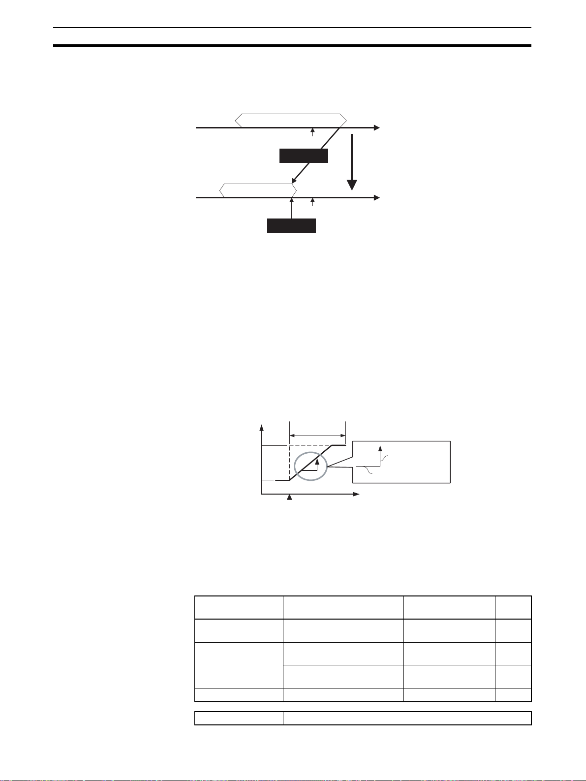
Setting Control Specifications Section 5-3
The SP will not be changed automatic ally, even if the input type or SP
Limiter is changed. A lthough the SP will not be changed automatically,
the internal SP used for control wi ll be limited to th e input range or SP
Limiter (whichever range is narrower).
SP Limiter range
SP
Internal SP
SP Limiter range
SP
Internal SP
MV Upper Limit
(2) The SP is not change d, but the internal SP used for contr ol is li mited by
the upper limit of the input range.
(3) The decimal point position is the same as set for the Decimal Point Posi-
tion B parameter.
5-3-4 Setting the SP Ramp
The SP ramp function r estr icts the width of cha nges in t he set point as a rate
of change. When the SP ramp function is enabled and the change width
exceeds the specified rate of change, this function can restrict the set p oint
within an area, as shown in the following diagram.
While the SP ramp fun ction is op erating, contr ol will be performed n ot for the
specified set point but rather for the set point r estri cted by the rate of change
set for the SP ramp function.
SP
SP Ramp
SP after change
SP before change
Point of change
SP Ramp Rise
Value
SP Ramp Time Unit
Time
The rate of change dur ing SP ramp operation is specifie d by the SP Ramp
Rise Value, SP Ramp Fall Value, and SP Ramp Time Unit parameters. The
SP ramp function will operate when the SP Ramp Rise Value or SP Ramp F all
Value is not set to 0 (disabled).
The Ramp SP can be checked by using the Internal SP parameter.
Variab le type Parameter name Setting/mo nitorin g
E5/A5 (See note 1.) SP Ramp Time Unit
(Channel)
D0/90 SP Ramp Rise Value
(Bank)
SP Ramp Fall Value
(Bank)
C4/84 Internal SP (Channel) −1999 to 9999 EU ---
0: Seconds
1: Minutes
0 to 9999 EU/s or min
(See note 2.)
0 to 9999 EU/s or min
(See note 2.)
range
Default
1
0
0
72
Conditions for use No special conditions.
Page 94

Setting Control Specifications Section 5-3
Note (1) This parameter can be set only when operation is stopped.
(2) The function is stopped if this parameter is set to 0. The unit is determined
by the setting of the SP Ramp Time Unit parameter.
Refer to 5-7-1 Bank Function for details on banks.
The decimal point position is the same as set for the Decimal Point Position B parameter.
Note Refer to 5-4-7 Alarm SP Selection for details on alarms during SP
ramp operation.
Operation at Startup If the SP ramp function is enabled when the Controller is turned ON or
switched from STOP to RUN mode, the process value may reach the set point
using the SP ramp functi on in the same way as changing the set poin t. In th is
case, operation is carried out with the process value regarded as the set point
before the change was made.
SP ramp operation at s tartup depends on the relationship between the process value and the set point, as shown in the following diagrams.
SP
Process
value
SP
PV < SP
Rising
SP ramp
Time
Power ON
Process
value
SP
SP
PV > SP
Falling
SP ramp
Power ON
When performing gradient temperature control, the following procedure is
used to determine the start point for the SP ramp.
1. The channel in the group with the largest deviation (difference between SP
and PV) is found.
2. The PV for the channel with the largest deviation is used as the start point
for the SP ramp.
3. For all other channels, the difference is found between that channel’s SP
and the SP for the channel with the largest deviation. The start point for the
SP ramp is the start point for the channel with the largest deviation plus this
difference.
Example 1
CH SP PS Deviation SP set value SP ramp start
1 150 25 125 0 (=150-150) 18 (=18+0)
2 150 21 129 0 (=150-150) 18 (=18+0)
3 150 18 132 (max.) 0 (=150-150) 18 (=18+0)
point
Time
Example 2
CH SP PS Deviation SP set value SP ramp start
point
1 110 105 5 -5 (=110-115) 95 (=100-5)
2 115 100 15 (max.) 0 (=115-115) 100 (=100-0)
3120130−10 5 (=120-115) 105 (=100+5)
Operation Example using Example 1 Values
73
Page 95

Setting Control Specifications Section 5-3
SP
PV1
PV2
PV3
Start of operation
SP ramp
Restrictions during
SP Ramp Operation
• Autotuning is started after the SP ramp operation has been completed.
• The SP ramp operation will continue even if operation is switched to manual mode.
• When control is stopped or an error occ urs, the SP ramp funct ion will be
disabled.
5-3-5 Setting the Manipulated Variab le (MV)
■ Manual MV
If control is set to manual mode, the standard control function will stop and the
MV set in the Manual MV parameter can be output.
Variable type Parameter name Setting range Default
D5/95
Conditions for use The control method must be set to 2-PID control in manual
Actual MV
100.0%
0.0%
Manual MV (Channel)
mode.
Manual MV
−5.0 to 105.0%
0
Note Refer to 6-4-11 Operation Commands for details on using an operat ion com-
Operation When
Switching between Auto
and Manual Modes
74
−5.0% 105.0%100.0%
Use an event input or operation command to switch between auto mode
(standard control) and manual mode. When using an event input to switch
modes, set the Event Input Assignment parameter to Auto (0)/Manual (1).
After the event input is set, it will operate as follows:
Event input Operation
OFF Auto Mode
ON Manual Mode
mand to switch the mode.
Check the Channel Status parameter (variable type C4/84) to confirm whether
the Controller is in auto mode or manual mode.
The following diagram shows the operation when the mode is switched
between auto mode and manual mode.
Page 96
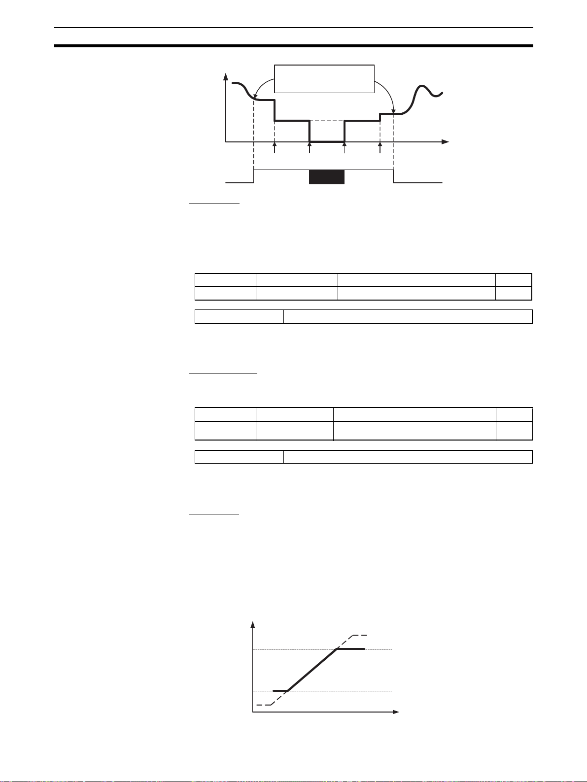
Setting Control Specifications Section 5-3
e
MV
Manual
Auto
Inherits the MV that existed
before the mode change.
MV
changes
Power
OFF
Power
interrupted
PowerONMV
Tim
changes
■ MV at Stop
This parameter sets the MV when control is stopped.
For heating/cooling contr ol, the MV at Stop p arameter applies t o the cooling
side if the MV is negative and to the heating side if the MV is positive.
The default is 0.0, so an MV will not be output for either standard or heating /
cooling control with the default setting.
Variable type Parameter name Setting range Default
D5/95
MV at Stop (Channel)
−5.0 to 105.0%
Conditions for use No special conditions.
The order of pr iority is as follows: Manual MV > MV at Stop > MV at PV
Error.
0
■ MV at PV Error
This parameter sets the MV when an input error or remote SP input error
occurs.
Variable type Parameter name Setting range Default
D5/95
MV at PV Error
(Channel)
−5.0 to 105.0%
Conditions for use No special conditions.
The order of pr iority is as follows: Manual MV > MV at Stop > MV at PV
Error.
■ MV Limiter
This function limits the MV output by applying upper a nd lower limits to the
calculated MV.
• The following MVs take priority over the MV limits.
•Manual MV
•MV at Stop
• MV at PV Error
Output
100%
MV Upper Limit
0
MV Lower Limit
0%
75
Page 97

Setting Control Specifications Section 5-3
Variable type Parameter name Setting range Default
D5/95
Conditions for use No special conditions.
MV Upper Limit (Channel) −5.0 to 105.0%
MV Lower Limit (Channel) −5.0 to 105.0%
105.0
−5.0
Note Set the limits so that the MV Upper Limit > MV Lower Limit.
If the MV Lower Limit > MV Upper Limit, the larger value will function as the
MV Upper Limit.
5-3-6 Tuning
Gradient Tuning (GT) Gradient temperature control finds the relationship between points with
mutual interference and performs cont rol. Gradient tun ing (GT) is a ser ies of
operations that automatic ally measure th e degree of mutual interference and
executes PID tuning at the same time, to adjust the in ternal parameters tha t
are used to find this relationship.
Always execute GT only when all groups (includi ng 2-PID contr ol groups ) are
stopped.
• GT cannot be executed in RUN or MANUAL modes.
• An operation command is used to execute and cancel GT. Ref er to 6-4-11
Operation Commands for details.
• GT automatically c alcu lat es th e di fferences in c hara cteristics of the different control objects for eac h channel and finds the rela tionship between
these differences. As a result, the differences in character istics for each
channel does not ap pear as differences in PID values. The PID values
calculated using GT will be the same for all channels in the group.
• GT will stop under the following conditions.
• If an input error has occurred.
• If the PV for the channel with outputs ON exceeds the SP.
• If an operation command is executed for STOP or MANUAL modes or
to cancel GT.
• If the Operation During Error (Selection A/C/D) parameter is set to MV
at PV Error or the conditions for stopping control have been occurred
• If an internal communications error has occurred
• If the internal parameters c annot be cal culated correctly f rom the G T
measurement results
• The following parameters are usually used at the default settings.
Variable type Parameter name Setting range Default
E5/A5
GT Natural Cooling Time
(Common)
GT Stabilization Band
(Common)
0 to 9999 s 300
0.0 to 999. 9 EU (See note 2.) 1.0
76
Conditions for use Gradient temperature control
Note (1) This parameter can be set only while operation is stopped.
(2) The decimal point posi tion is determi ned by the setting for the Decimal
Point Position B parameter. If, however, the Decimal Point Position B parameter is set to 0 (****), it will be treated as being set to 1 (***.*).
Page 98

Setting Control Specifications Section 5-3
■ GT Natural Cooling Time
Channel outputs within a group tur n ON in order during GT. The time from
when one output tur ns OFF until the next output tur ns ON can be adjusted
using the GT Natural Cooling Time parameter.
If here is a period wh ere the temperature for the previous channel has not
returned to room tempera ture by the time the next output turns ON, incre ase
the setting for the GT Natural Cooling Time. If, on the other hand, ch annels
immediately retur n to room temperature in all periods, then shor ten the GT
Natural Cooling Time. This will shorten the execution time for GT.
■ GT Stabilization Band
If the temperature of a channel inc reases by more than the value set for the
GT Stabilization Band parameter after the output turns ON, the inc rease is
treated as the effect of interference.
Autotuning (AT) When autotuning (AT) is executed, the MV is forcibly changed, the control
subject's character istics are observed (with th e limit cycle method), and the
best PID constants are automatically set for the SP during execution.
• Autotuning cannot be executed while control is stopp ed, during manual
mode operation, or during ON/OFF control.
• Use an operation co mmand to execute autotuni ng. For details, r efer to 6-
4-11 Operation Commands.
• The only parameters that can be received during autotuning are RUN/
STOP, Auto/Manual, AT Execute/Cancel, Alar m 1/2/3 Latch Cancel, and
Alarm Latch Cancel All. Other parameters cannot be changed.
• If the STOP parameter is set during autotuning, autotuning will be cancelled and operation will stop. Autotuning will not be restarted even if RUN
is set again.
• Normally the following parameters are left at their default settings.
Variable type Parameter name Setting range Default
E5/A5
AT Calculated Gain (Common) 0.1 to 10.0
AT Hysteresis (Channel) 0.1 to 999.9 EU
Limit Cycle MV Amplitude (Common) 5.0 to 50.0%
Temporary AT Execution Judgment Deviation
(Channel)
(See note 2.)
0.0 to 999.9 EU
(See note 2.)
0.8
0.8
20.0
150.0
Conditions for use The control method must be set to sta ndard c ontrol a nd 2-PID
control.
Note (1) This parameter can be set only when operation is stopped.
(2) The decimal poin t position is deter mined by the se nsor selection. Wit h
analog inputs, the decimal po int position is determined by the Deci mal
Point Position para meter set ting. In this c ase, however, the 0 (****) decimal point position setting will be treated as setting 1 (***.*).
■ AT Calculated Gain
Sets the gain used whe n calculating the PID con stants in autotuning. Whe n
emphasizing flexibility, decrease the set value. When emphasizing stability,
increase the set value.
■ AT Hy steresis
The limit cycle operation du ring autotuning has a hysteresis whe n switching
ON and OFF. This parameter sets that hysteresis value.
77
Page 99

Setting Control Specifications Section 5-3
■ Limit Cycle MV Amplitude
Sets the MV amplitude during limit cycle operation in autotuning.
Note This parameter is disabled for 100% AT.
■ Temporary AT Execution Judgment Deviation
When autotuning has been executed, temporary autotuning will be executed if
the deviation specified in this parameter is exceeded.
Note This parameter is disabled for 100% AT.
■ 40% AT
• The width of MV variation in the lim it cycl e can b e chang ed with t he Limit
Cycle MV Amplitude parameter. In this case, autotuning will take longer to
execute than it does with 100% AT.
• The timing of the lim it cycle's onset depends on wh ether the deviation at
the start of autotuning (DV) is less than the Temporary AT Execution
Judgment Deviation.
Deviation < Temporary AT Execution
Judgment Deviation
Limit Cycle
MV Amplitude 40%
Temporary AT
Execution Judgment Deviation
(Default: 150.0)
Autotuning starts
Autotuning completed
Time
Process
value
Set point
Deviation ≥ Temporary AT Execution
Judgment Deviation
Limit Cycle
MV Amplitude 40%
Temporary AT
Execution Judgment Deviation
(Default: 150.0)
Autotuning starts
Autotuning completed
Process
value
Set point
Time
■ 100% AT
• When autotuning starts, it operates as shown below regardless of the
deviation (DV). When you want to shorten the time it takes for autotuning ,
select 100% AT.
Note The Limit Cycle MV Amplitude and Temporary AT Execution Judgment Devia-
tion parameters are disabled.
Process
value
Set point
Limit Cycle
MV Amplitude 100%
Time
Autotuning starts
Autotuning completed
5-3-7 Disturbance Overshoot Adjustment Function
The Disturbance Overshoot Adjustment Function adjusts the control waveform when an external disturbance impacts the system.
• When using this function, set the Disturbance Overshoot Adjustment
Function parameter to 1 (Enabled).
78
Page 100

Setting Control Specifications Section 5-3
2
• The disturbance response waveform can be adjusted with the Disturbance Gain and Disturbance Time Constant parameters.
Variable type Parameter name Setting range Default
E5/A5 (See note 1.)
D5/95
Disturbance Overshoot Adjustment
Function (Common)
Disturbance Gain (Channel) −1.00 to 1.00
Disturbance Time Constant
Disturbance Rectification Band
Disturbance Judgment Width
(Channel)
(Channel)
(Channel)
Conditions for use No special conditions.
Note (1) This parameter can be set only when operation is stopped.
(2) The decimal poin t position is deter mined by the se nsor selection. Wit h
analog inputs, the decimal po int position is determined by the Deci mal
Point Position para meter set ting. In this c ase, however, the 0 (****) decimal point position setting will be treated as setting 1 (***.*).
■ Disturbance Gain
• Overshooting due to a disturbance can be suppressed more by increasing
the Disturbance Gain.
• Overshooting due to a dis turbance can be increased by dec reasing the
Disturbance Gain.
• If the Disturbance Gain is set to 0, the Disturbance Overshoot Adjustment
Function will not operate.
0: Disabled
1: Enabled
0.01 to 99.99 s
0.0 to 999.9 EU
(See note 2.)
−199.9 to 999.9 EU
(See note 2.)
0
0.65
1.00
0.0
0.0
Disturbance Gain = −1
Temperature
SP
0
Disturbance Gain = −0.5
Disturbance Gain = 0
Disturbance Gain = 0.5
Disturbance Gain = 1
Time
■ Disturbance Time Constant
The recovery time from the disturbance can be made longer by increasing the
Disturbance Time Cons tant. The Disturbance Time Constant is normal ly left
at its default setting of 1. Use this parameter for fine-tuning when adjusting the
Disturbance Gain alone is not sufficient.
Temperature
SP
Disturbance Time Constant = 1
Disturbance Time Constant =
0
Time
79
 Loading...