

Page 1

EJ1 EtherCAT
Slave Unit
EJ1N-HFUC-ECT
Cat. No. H192-E1-01
User’s Manual
Page 2

NOTE
All rights reserved. No part of this publication may be reproduced, stored in a retrieval system, or transmitted, in
any form, or by any means, mechanical, electronic, photocopying, recording, or otherwise, without the prior
written permission of OMRON.
No patent liability is assumed with respect to the use of the information contained herein. Moreover, because
OMRON is constantly striving to improve its high-quality products, the information contained in this manual is
subject to change without notice. Every precaution has been taken in the preparation of this manual. Nevertheless, OMRON assumes no responsibility for errors or omissions. Neither is any liability assumed for damages
resulting from the use of the information contained in this publication.
Trademarks
• Sysmac and SYSMAC are trademarks or registered trademarks of OMRON Corporation in Japan and other
countries for OMRON factory automation products.
• EtherCAT® is registered trademark and patented technology, licensed by Beckhoff Automation GmbH, Germany.
Other company names and product names in this document are the trademarks or registered trademarks of their
respective companies.
Copyrights
Microsoft product screen shots reprinted with permission from Microsoft Corporation.
Page 3

Introduction
Thank you for purchasing an EJ1 EtherCAT Slave Unit.
This manual provides information required to use the EJ1 EtherCAT Slave Unit, including information
on functions, performance, and application methods.
Observe the following items when you use the EJ1 EtherCAT Slave Unit.
• Allow only a specialist with knowledge of electrical systems to handle the EJ1 EtherCAT Slave Unit.
• Read and understand this user’s manual completely and use the EJ1 EtherCAT Slave Unit correctly.
• Keep this user’s manual in a safe place where it will be available for reference when required.
Introduction
EJ1 EtherCAT Slave Unit User’s Manual (H192)
1
Page 4

Terms and Conditions Agreement
Terms and Conditions Agreement
Warranty, Limitations of Liability
Warranties
Exclusive Warranty
Omron’s exclusive warranty is that the Products will be free from defects in materials and workmanship for a period of twelve months from the date of sale by Omron (or such other period expressed in
writing by Omron). Omron disclaims all other warranties, express or implied.
Limitations
OMRON MAKES NO WARRANTY OR REPRESENTATION, EXPRESS OR IMPLIED, ABOUT
NON-INFRINGEMENT, MERCHANTABILITY OR FITNESS FOR A PARTICULAR PURPOSE OF
THE PRODUCTS. BUYER ACKNOWLEDGES THAT IT ALONE HAS DETERMINED THAT THE
PRODUCTS WILL SUITABLY MEET THE REQUIREMENTS OF THEIR INTENDED USE.
Omron further disclaims all warranties and responsibility of any type for claims or expenses based
on infringement by the Products or otherwise of any intellectual property right.
Buyer Remedy
Omron’s sole obligation hereunder shall be, at Omron’s election, to (i) replace (in the form originally
shipped with Buyer responsible for labor charges for removal or replacement thereof) the non-complying Product, (ii) repair the non-complying Product, or (iii) repay or credit Buyer an amount equal
to the purchase price of the non-complying Product; provided that in no event shall Omron be
responsible for warranty, repair, indemnity or any other claims or expenses regarding the Products
unless Omron’s analysis confirms that the Products were properly handled, stored, installed and
maintained and not subject to contamination, abuse, misuse or inappropriate modification. Return of
any Products by Buyer must be approved in writing by Omron before shipment. Omron Companies
shall not be liable for the suitability or unsuitability or the results from the use of Products in combination with any electrical or electronic components, circuits, system assemblies or any other materials or substances or environments. Any advice, recommendations or information given orally or in
writing, are not to be construed as an amendment or addition to the above warranty.
See http://www.omron.com/global/ or contact your Omron representative for published information.
Limitation on Liability; Etc
OMRON COMPANIES SHALL NOT BE LIABLE FOR SPECIAL, INDIRECT, INCIDENTAL, OR CONSEQUENTIAL DAMAGES, LOSS OF PROFITS OR PRODUCTION OR COMMERCIAL LOSS IN ANY
WAY CONNECTED WITH THE PRODUCTS, WHETHER SUCH CLAIM IS BASED IN CONTRACT,
WARRANTY, NEGLIGENCE OR STRICT LIABILITY.
Further, in no event shall liability of Omron Companies exceed the individual price of the Product on
which liability is asserted.
2
EJ1 EtherCAT Slave Unit User’s Manual (H192)
Page 5

Application Considerations
Suitability of Use
Omron Companies shall not be responsible for conformity with any standards, codes or regulations
which apply to the combination of the Product in the Buyer’s application or use of the Product. At
Buyer’s request, Omron will provide applicable third party certification documents identifying ratings
and limitations of use which apply to the Product. This information by itself is not sufficient for a complete determination of the suitability of the Product in combination with the end product, machine, system, or other application or use. Buyer shall be solely responsible for determining appropriateness of
the particular Product with respect to Buyer’s application, product or system. Buyer shall take application responsibility in all cases.
NEVER USE THE PRODUCT FOR AN APPLICATION INVOLVING SERIOUS RISK TO LIFE OR
PROPERTY WITHOUT ENSURING THAT THE SYSTEM AS A WHOLE HAS BEEN DESIGNED TO
ADDRESS THE RISKS, AND THAT THE OMRON PRODUCT(S) IS PROPERLY RATED AND
INSTALLED FOR THE INTENDED USE WITHIN THE OVERALL EQUIPMENT OR SYSTEM.
Terms and Conditions Agreement
Programmable Products
Omron Companies shall not be responsible for the user’s programming of a programmable Product, or
any consequence thereof.
Disclaimers
Performance Data
Data presented in Omron Company websites, catalogs and other materials is provided as a guide for
the user in determining suitability and does not constitute a warranty. It may represent the result of
Omron’s test conditions, and the user must correlate it to actual application requirements. Actual performance is subject to the Omron’s Warranty and Limitations of Liability.
Change in Specifications
Product specifications and accessories may be changed at any time based on improvements and other
reasons. It is our practice to change part numbers when published ratings or features are changed, or
when significant construction changes are made. However, some specifications of the Product may be
changed without any notice. When in doubt, special part numbers may be assigned to fix or establish
key specifications for your application. Please consult with your Omron’s representative at any time to
confirm actual specifications of purchased Product.
Errors and Omissions
Information presented by Omron Companies has been checked and is believed to be accurate; however, no responsibility is assumed for clerical, typographical or proofreading errors or omissions.
EJ1 EtherCAT Slave Unit User’s Manual (H192)
3
Page 6
Safety Precautions
WARNING
CAUTION
Indicates a potentially hazardous situation which, if not
avoided, is likely to result in slight or moderate injury or
occasionally, death or serious injury. And serious property damage may occur as well.
Indicates a potentially hazardous situation which, if not
avoided, is likely to result in minor or moderate injury or
property damage.
Safety Precautions
Notation and Definitions for Precautionary Information
The following notation is used in this manual to provide precautions required to ensure safe usage of
the EJ1 EtherCAT Slave Unit.
The safety precautions that are provided here are extremely important to safety. Always read and heed
information provided in all safety precautions.
The following notation is used.
Definitions of Warning and Caution
Symbols
Caution
Prohibition
Mandatory
Caution
Symbol Meaning
• General Caution
Indicates non-specific general cautions, warnings, and dangers.
• Electrical Shock Caution
Indicates possibility of electric shock under specific conditions.
• General Prohibition
Indicates non-specific general prohibitions.
• Disassembly Prohibition
Indicates prohibitions when there is a possibility of injury, such as
from electric shock, as the result of disassembly.
• General Caution
Indicates non-specific general cautions, warnings, and dangers.
4
EJ1 EtherCAT Slave Unit User’s Manual (H192)
Page 7
Warnings and Cautions
WARNING
CAUTION
Never use the product without installing protective circuit in network. Doing so may possibly
cause abnormal operation, and result in serious injury, property damage, or accident. To
operate your total system safely even if any equipment failure occurs, or any trouble is
caused by an external element, be sure to configure an external-control-circuit that consists
of emergency stop, interlock and limit circuits to provide double or triple safeguard.
Do not attempt to take the Unit apart. In particular, parts with high power supply voltages
are present in Units that supply power while power is supplied or immediately after power is
turned OFF. Touching any of these parts may result in electric shock. There are sharp parts
inside the Unit that may cause injury.
Safety Precautions
Do not touch the terminals while power is being supplied.
Doing so may occasionally result in minor injury due to electric shock.
Use power supplies that comply with the reinforced insulation specified in IEC 60664 for the
EJ1 external power supply and for the power supplies for devices connected to the EJ1. If
non-compliant power supplies are used, electric shock may occasionally result in minor
injury.
Do not allow pieces of metal, wire clippings, or fine metallic chips generated during installation to enter the product. Doing so may occasionally result in electric shock, fire, or malfunction.
Do not use the product where subject to flammable or explosive gas.
Otherwise, minor injury from explosion may occasionally occur.
Never disassemble, modify, or repair the product or touch any of the internal parts. Minor
electric shock, fire, or malfunction may occasionally occur.
Execute online editing only after confirming that no adverse effects will be caused by deviations in the timing of I/O. If you perform online editing, the task execution time may exceed
the task period, I/O may not be refreshed with external devices, input signals may not be
read, and output timing may change.
Always confirm safety at the destination node before you transfer Unit configuration information, parameters, settings, or other data from tools such as the Sysmac Studio.
The devices or machines may operate unexpectedly, regardless of the operating mode of
the controller.
EJ1 EtherCAT Slave Unit User’s Manual (H192)
5
Page 8

Precautions for Safe Use
Precautions for Safe Use
• The product is designed for indoor use only. Do not use the product outdoors or in any of the following locations.
• Places directly subject to heat radiated from heating equipment.
• Places subject to splashing liquid or oil atmosphere.
• Places subject to direct sunlight.
• Places subject to dust or corrosive gas (in particular, sulfide or ammonia gas)
• Places subject to intense temperature change.
• Places subject to icing or condensation.
• Places subject to vibration or strong shocks.
• Use and store the product within the rated temperature and humidity ranges. Provide forced-cooling
if required.
• To allow heat to escape, do not block the area around the temperature controller. Also, do not block
its ventilation holes.
• Be sure to wire properly with correct polarity of terminals.
• Do not wire terminals that do not have an identified use.
• Secure as much space as possible between the product and devices that generates a strong
high-frequency or surge. Separate the high-voltage or large-current power lines from other lines, and
avoid parallel or common wiring with the power lines when you are wiring to the terminals.
• Use the product within the rated load and power supply voltage.
• Make sure that the rated voltage is attained within two seconds of turning ON the power.
• The switch or circuit breaker must be located within an easy reach of the operator, and must be
marked as a disconnecting means for this unit.
• Do not use paint thinner or similar chemical to clean with. Use standard grade alcohol.
• Never touch the electric components, connectors, or patterns in the product with bare hands. Always
hold the product by its enclosure. Inappropriate handling of the product may occasionally damage
internal components due to static electricity.
• Use a switch, relay, or other device for turning OFF the power supply quickly. Gradually lowering the
voltage of the power supply may result in incorrect outputs or memory errors.
• Connect only the specified number of products in only a specified configuration.
• Mount the product to a DIN Rail mounted vertically to the ground.
• Make sure that the data transfer distance for EtherCAT is within the specified range, and use the
specified cables only.
• Do not bend a communications cable past its natural bending radius or pull in it with excessive force.
Also, do not place heavy objects on top of the cables or other wiring lines. Doing so may break the
cable.
• When transporting any Unit, use the special packing box for it. Also, do not subject the Unit to excessive vibration or shock during transportation.
• Do not drop any Unit or subject it to abnormal vibration or shock. Doing so may result in Unit malfunction or burning.
• Be sure that connectors with locking devices are properly locked into place.
• When wiring or installing the Units, do not allow metal fragments to enter the Units.
• Double-check all switches and other settings and double-check all wiring to make sure that they are
correct before turning ON the power supply. Use the correct wiring parts and tools when you wire the
system.
• Always turn OFF the external power supply to the Units before attempting any of the following.
• Mounting, removing, or replacing the Unit
• Setting the rotary switches
6
EJ1 EtherCAT Slave Unit User’s Manual (H192)
Page 9

Precautions for Safe Use
• Connecting cables, wiring, or changing the configuration
• If you change the fail-soft operation setting, the output status when the error occurs may also change.
Confirm safety before you change the fail-soft operation setting.
• Confirm that the controlled system will not be adversely affected before you perform any of the following operations.
• Changing the operating mode of the CPU Unit (including changing the setting of the Operating
Mode at Startup)
• Changing the user program or settings
• Changing set values or present values
• Forced refreshing
• Dispose of the product according to local ordinances as they apply.
• Do not allow foreign matter to enter the openings in the Unit. Doing so may result in Unit burning,
electric shock, or failure.
• Before installing the Unit, do not remove the enclosed cover seal from the connector opening on the
left end of the Unit.
• You can connect up to 16 Units for one End Unit. However, you can connect only one Advanced Unit.
Do not connect more than 16 Units.
• You can connect up to 32 Basic Units with branch wiring. Do not connect more than 32 Basic Units.
Observe the following precautions for EtherCAT communications.
• Make sure that the communications distance, number of nodes connected, and method of connection for EtherCAT are within specifications.
Do not connect EtherCAT Coupler Units to EtherNet/IP, a standard in-house LAN, or other networks.
An overload may cause the network to fail or malfunction.
• Malfunctions or unexpected operation may occur for some combinations of EtherCAT revisions of the
master and slaves. If you disable the revision check in the network settings, check the slave revision
settings in the master and the actual slave revisions, and then make sure that functionality is compatible in the manuals or other references. You can check the slave versions in the settings from the
Sysmac Studio and you can check the actual slave revisions from the Sysmac Studio or on slave
nameplates.
• After you transfer the user program, the CPU Unit is restarted and communications with the EtherCAT slaves are cut off. During that period, the slave outputs behave according to the slave settings.
The time that communications are cut off depends on the EtherCAT network configuration.
Before you transfer the user program, confirm that the system will not be adversely affected.
• EtherCAT communications are not always established immediately after the power supply is turned
ON. Use the system-defined variables in the user program to confirm that communications are established before attempting control operations.
• If frames sent to EtherCAT slaves are lost due to noise or other causes, slave I/O data is not communicated, and the intended operation is sometimes not achieved. Perform the following processing if
noise countermeasures are necessary.
Program the _EC_InDataInvalid (Input Data Invalid), _EC_InData1Invalid (Input Data 1 Invalid), and
_EC_InData2Invalid (Input Data 2 Invalid) system-defined variables as interlock conditions in the
user program.
Set the PDO communications consecutive timeout detection count setting in the EtherCAT master to
at least 2.
Refer to the NJ/NX-series CPU Unit Built-in EtherCAT Port User’s Manual (Cat. No. W505) for
details.
• When an EtherCAT slave is disconnected, communications will stop and control of the outputs will be
lost not only for the disconnected slave, but for all slaves connected after it. Confirm that the system
will not be adversely affected before you disconnect a slave.
• If you disconnect the cable from an EtherCAT slave to disconnect it from the network, any current
communications frames may be lost. If frames are lost, slave I/O data is not communicated, and the
EJ1 EtherCAT Slave Unit User’s Manual (H192)
7
Page 10

Precautions for Safe Use
intended operation is sometimes not achieved. Perform the following processing for a slave that
needs to be replaced.
Program the _EC_InDataInvalid (Input Data Invalid), _EC_InData1Invalid (Input Data 1 Invalid), and
_EC_InData2Invalid (Input Data 2 Invalid) system-defined variables as interlock conditions in the
user program.
Set the PDO communications consecutive timeout detection count setting in the EtherCAT master to
at least 2.
Refer to the NJ/NX-series CPU Unit Built-in EtherCAT Port User’s Manual (Cat. No. W505) for
details.
• Make sure that the PDO recording area for EtherCAT communications is correct.
8
EJ1 EtherCAT Slave Unit User’s Manual (H192)
Page 11

Precautions for Correct Use
Installation
• Connect the EJ1 EtherCAT Slave Unit to the left side of a Basic Unit or an End Unit.
• The EJ1 cannot be used linked to a CJ-series PLC.
Service Life
• Use the product within the following temperature and humidity ranges.
Temperature: −10 to 55°C (with no icing or condensation)
Humidity: 25% to 85%
When the Temperature Controller is incorporated in a control panel, make sure that the controller’s ambient temperature and not the panel’s ambient temperature does not exceed 55°C.
• The service life of electronic devices like the Temperature Controller is determined by the service
life of internal electronic components. Component service life is affected by the ambient temperature: the higher the temperature, the shorter the service life and the lower the temperature, the
longer the service life. Therefore, the service life can be extended by lowering the temperature of
the Temperature Controller.
• Mounting two or more Temperature Controllers side by side, or mounting Temperature Controllers
above each other may cause heat to build up inside the Temperature Controllers, which will
shorten their service life. If the Temperature Controllers are mounted above each other or side by
side, use forced cooling by fans or other means of air ventilation to cool down the Temperature
Controllers.
However, be sure not to cool only the terminals. Doing so will result in measurement errors.
• Take appropriate and sufficient countermeasures when installing the controller in the following
locations.
Locations subject to static electricity or other forms of noise
Locations subject to strong electromagnetic fields
Locations subject to possible exposure to radioactivity
Locations close to power lines
Precautions for Correct Use
Precautions for Operation
• It takes a certain amount of time for the outputs to turn ON from after the power supply is turned
ON. Due consideration must be given to this time when designing control panels, etc.
• It takes 30 minutes from the time the product is turned ON until the correct temperature is indicated. Always turn ON the power supply at least 30 minutes before starting temperature control.
• Avoid using the Temperature Controller near a radio, television set, or other wireless device. Its
use would result in reception disturbance.
EJ1 EtherCAT Slave Unit User’s Manual (H192)
9
Page 12

Preparations for Use
Preparations for Use
Be sure to thoroughly read and understand the manual provided with the product, and check the following points.
Timing Check point Details
Purchasing the
product
Setting the Unit Product installa-
Wiring Terminal wiring Do not subject the terminal screws to excessive stress (force) when
Operating environment
Product appearance
Product model
and specifications
tion location
Power supply
inputs
Ambient temperature
Vibration and
shock
Foreign particles Install the product in a location that is not subject to liquid or foreign par-
After purchase, check that the product and packaging are not dented or
otherwise damaged. Damaged internal parts may prevent optimum control.
Make sure that the purchased product meets the required specifications.
Provide sufficient space around the product for heat dissipation. Do not
block the vents on the product.
tightening them.
Make sure that there are no loose screws after tightening terminal
screws to the specified torque of 0.25 to 0.30 N·m.
Be sure to confirm the polarity for each terminal before wiring the terminal block and connectors.
Wire the power supply inputs correctly. Incorrect wiring will result in damage to the internal circuits.
The ambient operating temperature for the product is −10 to 55°C (with
no condensation or icing). To extend the service life of the product, install
it in a location with an ambient temperature as low as possible. In locations exposed to high temperatures, if necessary, cool the products
using a fan or other cooling method.
Check whether the standards related to shock and vibration are satisfied
at the installation environment. (Install the product in locations where the
conductors will not be subject to vibration or shock.)
ticles entering the product. If sulfide, chlorine, or other corrosive gases
are present, remove the source of the gas, install a fan, or use other
countermeasures to protect the product.
10
EJ1 EtherCAT Slave Unit User’s Manual (H192)
Page 13

Regulations and Standards
Conformance to EU Directives
Applicable Directives
EMC Directives
Concepts
EMC Directives
OMRON devices that comply with EU Directives also conform to the related EMC standards so
that they can be more easily built into other devices or the overall machine. The actual products
have been checked for conformity to EMC standards. Whether the products conform to the standards in the system used by the customer, however, must be checked by the customer.
EMC-related performance of the OMRON devices that comply with EU Directives will vary
depending on the configuration, wiring, and other conditions of the equipment or control panel on
which the OMRON devices are installed. The customer must, therefore, perform the final check to
confirm that devices and the overall machine conform to EMC standards.
Regulations and Standards
Conformance to EU Directives
To ensure that the machine or device in which the EJ-series Unit is used complies with EU Directives, the Unit must be installed as follows:
• The EJ1 EtherCAT Slave Unit must be installed within a control panel.
• You must use reinforced insulation or double insulation for the DC power supplies used for the
communications power supply, internal power supply, and I/O power supplies.
• EJ-series Units that comply with EU Directives also conform to the Common Emission Standard
(EN 61326). Radiated emission characteristics (10-m regulations) may vary depending on the
configuration of the control panel used, other devices connected to the control panel, wiring, and
other conditions. You must therefore confirm that the overall machine or equipment complies with
EU Directives.
• The Unit is a Class A product (products for industrial environments). In residential environment
areas it may cause radio interference, in which case the user may be required to take adequate
measures to reduce interference.
EJ1 EtherCAT Slave Unit User’s Manual (H192)
11
Page 14

Revision History
Revision History
A manual revision code appears as a suffix to the catalog number at the bottom of the back cover of the
manual.
Cat. No. H192-E1-01
Revision code Date Revised content
01 October 2015 Original production
Revision code
12
EJ1 EtherCAT Slave Unit User’s Manual (H192)
Page 15

Related Manuals
Related Manuals
The manuals related to the EJ1 EtherCAT Slave Unit are configured as shown in the following tables.
Refer to these manuals as required.
EJ1
Cat. No. Model number Manual name Application Description
H192
(This manual)
H142 EJ1N-TC2
---
Online Help
EJ1N-HFUC-ECT EJ1 EtherCAT
EJ1N-TC4
EJ1C-EDU
EST2-2C-MV4 CX-Thermo Ver.
Slave Unit User’s
Manual
EJ1 Modular Temperature Controllers User's Manual
4. (online help)
Learning the basic specifications of the EJ1 EtherCAT
Slave Unit, including introductory information, designing,
and maintenance.
Learning the basic specifications of the EJ1 Temperature
Controllers, including introductory information, designing, installation, and
maintenance.
Learning the operating procedures of the CX-Thermo.
The following information is provided on
the EJ1 EtherCAT Slave Unit.
• Overview and features
• System configuration
• Installation and wiring
• Troubleshooting
The following information is provided on
the EJ1 Temperature Controllers.
• Overview and features
• System configuration
• Mounting and wiring
• Troubleshooting
Describes how to set parameters and
adjust devices (i.e., components such as
Temperature Controllers) using the
CX-Thermo.
NJ/NX-series Master Units
Cat. No. Model number Manual name Application Description
W505 NX701-
NJ501-
NJ301-
NJ101-
W500 NJ501-
NJ301-
NJ101-
NJ/NX-series CPU
Unit Built-in EtherCAT Port User's
Manual
NJ-series CPU Unit
Hardware User’s
Manual
Using the built-in EtherCAT
port on an NJ/NX-series CPU
Unit.
Learning the basic specifications of the NJ-series CPU
Units, including introductory
information, designing, installation, and maintenance.
Mainly hardware information
is provided.
Information on the built-in EtherCAT port
is provided
This manual provides an introduction and
information on the configuration, features,
and setup.
Use this manual together with the
NJ-series CPU Unit Hardware User's
Manual (Cat. No. W500) and
NJ/NX-series CPU Unit Software User's
Manual (Cat. No. W501).
An introduction to the entire NJ-series
system is provided along with the following information on the CPU Unit.
• Features and system configuration
• Introduction
• Part names and functions
• General specifications
• Installation and wiring
• Maintenance and inspection
Use this manual together with the
NJ/NX-series CPU Unit Software User's
Manual (Cat. No. W501).
EJ1 EtherCAT Slave Unit User’s Manual (H192)
13
Page 16

Related Manuals
Cat. No. Model number Manual name Application Description
W535 NX701- NX-series CPU Unit
Hardware User’s
Manual
W501 NX701-
NJ501-
NJ301-
NJ101-
W502 NX701-
NJ501-
NJ301-
NJ101-
W504 SYSMAC-SE2 Sysmac Studio Ver-
NJ/NX-series CPU
Unit Software
User´s Manual
NJ/NX-series
Instructions Reference Manual
sion 1 Operation
Manual
Learning the basic specifications of the NX-series CPU
Units, including introductory
information, designing, installation, and maintenance.
Mainly hardware information
is provided.
Learning how to program and
set up an NJ/NX-series CPU
Unit.
Mainly software information is
provided.
Learning detailed specifications on the basic instructions
of an NJ/NX-series CPU Unit.
Learning about the operating
procedures and functions of
the Sysmac Studio.
An introduction to the entire NX-series
system is provided along with the following information on the CPU Unit.
• Features and system configuration
• Introduction
• Part names and functions
• General specifications
• Installation and wiring
• Maintenance and inspection
Use this manual together with the
NJ/NX-series CPU Unit Software User's
Manual (Cat. No. W501).
The following information is provided on
an NJ/NX-series CPU Unit.
• CPU Unit operation
• CPU Unit features
• Initial settings
• Use this manual together with IEC
61131-3-based programming language
specifications and the NJ-series CPU
Unit Hardware User's Manual (Cat. No.
W500).
The instructions in the instruction set (IEC
61131-3 specifications) are described.
When programming, use this manual
together with the NJ-series CPU Unit
Hardware User's Manual (Cat. No. W500)
and NJ/NX-series CPU Unit Software
User's Manual (Cat. No. W501).
Describes the operating procedures of
the Sysmac Studio.
G3ZA Multi-channel Power Controllers
Cat. No. Model number Manual name Application Description
Z200 G3ZA-4H203-FLK-UTU
G3ZA-4H403-FLK-UTU
G3ZA-8A203-FLK-UTU
G3ZA-8A403-FLK-UTU
G3ZA Multi-channel Power Controller User’s Manual
Using the G3ZA to perform
high-precision control of
heater power with RS-485
serial communications (CompoWay/F) from an EJ1 or
PLC.
The following information is provided on the G3ZA.
• Overview and features
• Installation and wiring
• Setting RS-485 serial communications
• Basic functions
G3PW Power Controllers
Cat. No. Model number Manual name Application Description
Z280 G3PW-A220EC-C-FLK
G3PW-A230EC-C-FLK
G3PW-A245EC-C-FLK
G3PW-A260EC-C-FLK
G3PW-A220EC-S-FLK
G3PW-A230EC-S-FLK
G3PW-A245EC-S-FLK
G3PW-A260EC-S-FLK
G3PW-series
Power Controller
User's Manual
Using the G3PW under phase
control or cyclic control to
perform control that achieves
higher precision than with the
G3ZA on heater power with a
continuous proportional output or with RS-485 serial
communications (CompoWay/F) from an EJ1.
The following information is provided on the G3PW.
• Overview and features
• Installation and wiring
• Setting RS-485 serial communications
• Basic functions
14
EJ1 EtherCAT Slave Unit User’s Manual (H192)
Page 17

Meanings of Abbreviations and Terms
Meanings of Abbreviations and Terms
The following abbreviations and terms are used in this manual.
Abbreviation or term Meaning
CompoWay/F commands/responses
EDU EJ1 End Unit
Basic Unit EJ1 Basic Unit
Advanced Unit EJ1 EtherCAT Slave Unit
Temperature Controller One of the EJ1 Basic Units given above.
communications unit number
Also called “FINS-mini commands/responses.”
This manual uses the term “CompoWay/F commands/responses.”
• TC4: Four-channel Basic Unit
• TC2: Two-channel Basic Unit
An identification number in CompoWay/F communications for a Temperature Controller connected to an EJ1 EtherCAT Slave Unit.
Set the communications unit number with rotary switch 1 and DIP switch 2 on each
Basic Unit.
EJ1 EtherCAT Slave Unit User’s Manual (H192)
15
Page 18

Meanings of Abbreviations and Terms
16
EJ1 EtherCAT Slave Unit User’s Manual (H192)
Page 19

1I
2
3
4
5
7
8
A
1I
2
3
4
5
6
7
8
A
7
Appendices
Index
Part Names and EtherCAT Communications Overview
Installation and Connection
Troubleshooting
Maintenance and Inspection
6
Specifications and Procedures
Features and System
Configuration
Using the EJ1 EtherCAT Slave Unit with PDO
Communications
Using the EJ1 EtherCAT Slave Unit with SDO
Communications
Sections in this Manual
Sections in this Manual
EJ1 EtherCAT Slave Unit User’s Manual (H192)
17
Page 20

CONTENTS
CONTENTS
Introduction ..............................................................................................................1
Terms and Conditions Agreement ..........................................................................2
Warranty, Limitations of Liability .................................................................................................................. 2
Application Considerations .......................................................................................................................... 3
Disclaimers .................................................................................................................................................. 3
Safety Precautions ...................................................................................................4
Notation and Definitions for Precautionary Information ............................................................................... 4
Symbols....................................................................................................................................................... 4
Warnings and Cautions ............................................................................................................................... 5
Precautions for Safe Use.........................................................................................6
Precautions for Correct Use.................................................................................... 9
Preparations for Use ..............................................................................................10
Regulations and Standards................................................................................... 11
Conformance to EU Directives .................................................................................................................. 11
Revision History .....................................................................................................12
Related Manuals .....................................................................................................13
EJ1............................................................................................................................................................. 13
NJ/NX-series Master Units ........................................................................................................................ 13
G3ZA Multi-channel Power Controllers ..................................................................................................... 14
G3PW Power Controllers........................................................................................................................... 14
Meanings of Abbreviations and Terms.................................................................15
Sections in this Manual .........................................................................................17
CONTENTS..............................................................................................................18
Section 1 Features and System Configuration
1-1 Overview and Features ......................................................................................................... 1-2
1-1-1 Overview .....................................................................................................................................1-2
1-1-2 Features ...................................................................................................................................... 1-2
1-2 System Configuration ........................................................................................................... 1-3
1-3 Unit Models and Overview of Functions ............................................................................. 1-5
1-3-1 Unit Model Number .....................................................................................................................1-5
1-3-2 Overview of Functions.................................................................................................................1-5
Section 2 Specifications and Procedures
2-1 Specifications ........................................................................................................................ 2-2
2-1-1 General Specifications ................................................................................................................ 2-2
2-1-2 Function Specifications ............................................................................................................... 2-2
2-1-3 EtherCAT Slave Communications Specifications........................................................................ 2-3
18
EJ1 EtherCAT Slave Unit User’s Manual (H192)
Page 21

CONTENTS
2-2 Application Procedures ........................................................................................................ 2-4
2-2-1 Hardware Setup Procedure ........................................................................................................ 2-4
2-2-2 Software Setup Procedure.......................................................................................................... 2-5
Section 3 Part Names and EtherCAT Communications Overview
3-1 Part Names and Functions ................................................................................................... 3-2
3-1-1 Appearance and Names of Parts on the Front Panel ................................................................. 3-2
3-1-2 Meanings of Indicators................................................................................................................ 3-3
3-1-3 Node Address Setting Switches ................................................................................................. 3-3
3-1-4 EtherCAT Communications Connectors..................................................................................... 3-4
3-2 EtherCAT Communications Overview ................................................................................. 3-5
3-2-1 Structure of CAN Application Protocol over EtherCAT (CoE)..................................................... 3-5
3-2-2 EtherCAT Slave Information File (ESI Files)............................................................................... 3-6
3-2-3 State Transitions for EtherCAT Communications........................................................................ 3-7
3-2-4 Process Data Objects (PDOs) .................................................................................................... 3-8
3-2-5 Service Data Objects (SDOs) ................................................................................................... 3-10
Section 4 Installation and Connection
4-1 Installing the EJ1 EtherCAT Slave Unit ............................................................................... 4-2
4-2 EtherCAT Network Wiring ..................................................................................................... 4-3
4-2-1 Installation Precautions............................................................................................................... 4-3
4-2-2 Preparations for Installation ........................................................................................................ 4-3
4-2-3 Recommended EtherCAT Cables............................................................................................... 4-4
4-3 Wiring the Temperature Controllers .................................................................................... 4-5
Section 5 Using the EJ1 EtherCAT Slave Unit with PDO Communi-
cations
5-1 EJ1 PDO Communications Overview .................................................................................. 5-2
5-2 How Data Is Sent and Received with PDO Communications ............................................ 5-3
5-2-1 CompoWay/F Commands and Responses ................................................................................ 5-3
5-2-2 Control Commands and Responses........................................................................................... 5-5
5-3 PDO Mapping Data Overview ............................................................................................... 5-6
5-3-1 Types of PDO Mapping Data...................................................................................................... 5-6
5-3-2 PDO Mapping Data List.............................................................................................................. 5-7
5-4 PDO Mapping Data Details.................................................................................................... 5-8
5-4-1 Output Notification Data (Communications Master to EJ1 EtherCAT Slave Unit) ...................... 5-8
5-4-2 Input Notification Data (EJ1 EtherCAT Slave Unit to Communications Master) ....................... 5-10
5-4-3 Sysmac Error Status................................................................................................................. 5-14
5-5 Writing User Programming................................................................................................. 5-15
5-5-1 Handshaking with the EJ1 EtherCAT Slave Unit with User Programming................................ 5-15
5-5-2 Handshaking with the EJ1 EtherCAT Slave Unit with User Programming................................ 5-16
5-5-3 Procedures for Sending Control Commands and Receiving Responses ................................. 5-17
5-6 Example Procedures for Sending CompoWay/F Commands
and Receiving Responses .................................................................................................. 5-18
5-6-1 Example of Sending and Receiving Data without Dividing into Parts....................................... 5-18
5-6-2 Example of Sending and Receiving Data in Parts .................................................................... 5-21
5-7 Setting CompoWay/F Frames............................................................................................. 5-25
5-7-1 Output Data and Input Data Contents ...................................................................................... 5-25
5-7-2 Storing Output Data and Input Data in Array Variables ............................................................ 5-27
5-7-3 Setting the PDO Mappings for I/O Data.................................................................................... 5-28
5-8 Assigning Device Variables................................................................................................ 5-32
EJ1 EtherCAT Slave Unit User’s Manual (H192)
19
Page 22

CONTENTS
Section 6 Using the EJ1 EtherCAT Slave Unit with SDO Communi-
cations
6-1 Overview................................................................................................................................. 6-2
6-2 Abort Codes ........................................................................................................................... 6-3
Section 7 Troubleshooting
7-1 Error Notification Methods ...................................................................................................7-2
7-2 Error List ................................................................................................................................ 7-3
7-2-1 Errors Detected during Boot Process.......................................................................................... 7-3
7-2-2 EtherCAT Communications Errors..............................................................................................7-4
7-2-3 Errors Detected during a Software Process................................................................................7-5
7-3 Error Notifications Based on the Sysmac Error Status ..................................................... 7-6
7-3-1 Sysmac Error Status ...................................................................................................................7-6
7-3-2 Checking and Responding to Event Codes ................................................................................7-7
7-4 Error Notifications Provided with Emergency Messages .................................................. 7-8
7-4-1 Emergency Messages.................................................................................................................7-8
7-5 Error Notifications Based on the AL Status........................................................................ 7-9
Section 8 Maintenance and Inspection
8-1 Cleaning and Inspection ....................................................................................................... 8-2
8-1-1 Cleaning ...................................................................................................................................... 8-2
8-1-2 Inspection Methods .....................................................................................................................8-2
8-1-3 Inspection Items .......................................................................................................................... 8-3
8-2 Replacing Units...................................................................................................................... 8-4
8-2-1 Unit Replacement Precautions.................................................................................................... 8-4
8-2-2 Unit Replacement Procedure ......................................................................................................8-4
Appendices
A-1 Dimensions ............................................................................................................................A-2
A-1-1 EJ1N-HFUC-ECT........................................................................................................................A-2
A-2 Sample Programming ...........................................................................................................A-3
A-2-1 Items Common to All Programming Samples .............................................................................A-3
A-2-2 Sending CompoWay/F Commands and Receiving Responses ..................................................A-6
A-2-3 Restart Port .................................................................................................................................A-8
A-3 CoE Objects ...........................................................................................................................A-9
A-3-1 Object Dictionary Area ................................................................................................................A-9
A-3-2 Data type.....................................................................................................................................A-9
A-3-3 Communications Objects ..........................................................................................................A-10
A-3-4 PDO Mapping Objects ..............................................................................................................A-11
A-3-5 Sync Manager Communications Objects ..................................................................................A-14
A-3-6 Manufacturer-specific Object 1 .................................................................................................A-15
A-3-7 Device Profile Area ...................................................................................................................A-17
Index
20
EJ1 EtherCAT Slave Unit User’s Manual (H192)
Page 23

Features and System Configuration
This section describes the features of the EJ1 EtherCAT Slave Unit and the system
configuration in which the EJ1 EtherCAT Slave Unit is used.
1-1 Overview and Features . . . . . . . . . . . . . . . . . . . . . . . . . . . . . . . . . . . . . . . . . 1-2
1-1-1 Overview . . . . . . . . . . . . . . . . . . . . . . . . . . . . . . . . . . . . . . . . . . . . . . . . . . . . . . 1-2
1-1-2 Features . . . . . . . . . . . . . . . . . . . . . . . . . . . . . . . . . . . . . . . . . . . . . . . . . . . . . . 1-2
1-2 System Configuration . . . . . . . . . . . . . . . . . . . . . . . . . . . . . . . . . . . . . . . . . . 1-3
1-3 Unit Models and Overview of Functions . . . . . . . . . . . . . . . . . . . . . . . . . . . 1-5
1-3-1 Unit Model Number . . . . . . . . . . . . . . . . . . . . . . . . . . . . . . . . . . . . . . . . . . . . . . 1-5
1-3-2 Overview of Functions . . . . . . . . . . . . . . . . . . . . . . . . . . . . . . . . . . . . . . . . . . . 1-5
1
EJ1 EtherCAT Slave Unit User’s Manual (H192)
1 - 1
Page 24

1 Features and System Configuration
1-1 Overview and Features
This section introduces the EJ1 EtherCAT Slave Unit and describes its features.
1-1-1 Overview
The EJ1 EtherCAT Slave Unit is a communications unit used to connect EJ1 Modular Temperature
Controllers as slaves on an EtherCAT network.
You can send CompoWay/F commands from a user program through PDO communications to perform
handshaking with an EJ1 EtherCAT Slave Unit in order to write/read values in EJ1 Basic Units connected to the EJ1 EtherCAT Slave Unit.
1-1-2 Features
The EJ1 EtherCAT Slave Unit has the following features.
• You can connect up to 15 Basic Units in EJ1 Modular Temperature Controllers to communicate
between the EtherCAT communications master and the Basic Units. If you use distributed placement,
you can connect up to 32 Basic Units.
• You can send the required commands with the CompoWay/F communications protocol for OMRON
components from the EtherCAT communications master to read/write present values and set values
or to perform other processing.
1 - 2
EJ1 EtherCAT Slave Unit User’s Manual (H192)
Page 25
1 Features and System Configuration
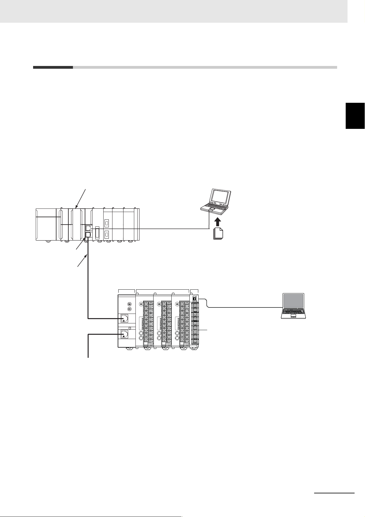
Connect the following to port B:
• When using distributed placement,
use an RS-485 cable to connect ports B between two EDUs.
Note: Programmable Terminals (PTs) cannot be connected.
PC
Connect the following to the port A
connector: Use the E58-CIFQ1 (sold
separately) to connect port A to USB
port on a computer running the
CX-Thermo.
(A)
EJ1 EtherCAT Slave Unit
EJ1N-HFUC-ECT
(B)
EJ1-TC4 or
EJ1-TC2 Units
(C)
EJ1-EDU
(D)
CX-Thermo
(for setup)
(H) Communications cable
Ethernet cable
(E) EtherCAT master
NJ/NX-series CPU Unit or non-OMRON master
(F) Sysmac Studio
Support Software
(G) ESI files
Built-in EtherCAT port
.xml
Connect to peripheral USB port or built-in EtherNet/IP port on
NJ/NX-series CPU Unit.
EtherCAT
1-2 System Configuration
This section describes the overall system configuration in which an EJ1 EtherCAT Slave Unit is used.
The EJ1 EtherCAT Slave Unit is connected to an EtherCAT network that is connected to an
NJ/NX-series CPU Unit or a non-OMRON EtherCAT communications master.
The EJ1 EtherCAT Slave Unit is connected as the far left module, and EJ1 Basic Units (TC4/TC2)
are connected on the right of it. An EJ1 End Unit (EDU) is connected as the far right module.
The elements in the system configuration are described in the following system configuration diagram.
1-2 System Configuration
1
EJ1 EtherCAT Slave Unit User’s Manual (H192)
A maximum of 15 Basic Units can be connected side by side next to an EJ1 EtherCAT Slave Unit to
perform EtherCAT communications through the EJ1 EtherCAT Slave Unit.
If you use distributed placement through a RS-485 communications cable from the EDU, you can
connect a maximum of 32 Basic Units next to the EJ1 EtherCAT Slave Unit to perform EtherCAT
communications through the EJ1 EtherCAT Slave Unit.
Refer to the EJ1 Modular Temperature Controllers User’s Manual (Cat. No. H142) for information on
distributed placement.
1 - 3
Page 26

1 Features and System Configuration
Letter Item Description
(A) EJ1 EtherCAT Slave Unit This Unit is an EJ1 Advanced Unit.
(B) EJ1 Basic Units The Basic Units are modular temperature controllers with I/O.
(C) EJ1 End Unit (EDU) This Unit provides power to the connected Basic Units and
(D) CX-Thermo
(EST2-2C-MV)
(E) EtherCAT communications mas-
ter
(F) Sysmac Studio Support Software This computer software application is used to set up the EtherCAT
(G) ESI files ESI files contain information that is unique to the EJ1 EtherCAT
(H) EtherCAT communications cable Use a double-shielded cable with aluminum tape and braiding of
There are two models of Basic Units: The TC4 with four I/O channels and the TC2 with two I/O channels.
You can connect up to eight G3ZA Multi-channel Power Controllers
or V1.1 G3PW Power Controllers to each Basic Unit.
Advanced Unit. The End Unit must be connected as the far right
module when you use the EJ1 EtherCAT Slave Unit. You can connect up to 16 Units for one End Unit. However, you can connect
only one Advanced Unit.
This computer software application is used to set up and monitor
the EJ1 Basic Units.
An E58-CIFQ1 USB-Serial Conversion Cable is required to connect
the CX-Thermo. You can also use a K3SC-10 Interface Converter
to convert to RS-232C/RS-485 and thereby enable connecting to
more than one EJ1 EtherCAT Slave Unit at the same time.
This is an EtherCAT communications master, such as an
NJ/NX-series CPU Unit or a communications master from another
manufacturer.
network and make other settings. It is used to register an EJ1 EtherCAT Slave Unit in the EtherCAT network configuration.
The Sysmac Studio is also used to set the PDO mappings for the
EtherCAT communications master.
To change the default PDO sizes, edit the PDO mappings in the
communications master of the EJ1 EtherCAT Slave Unit in EtherCAT slave settings on the Sysmac Studio.
Slave Unit in XML format.
ESI files are required to connect OMRON EtherCAT slaves to controllers from other companies. To connect an EJ1 EtherCAT Slave
Unit to a controller from another company, install the ESI file for the
EJ1 EtherCAT Slave Unit in the configuration software that you are
using. For details on ESI files, refer to 3-2-2 EtherCAT Slave Infor-
mation File (ESI Files) on page 3-6
Ethernet category 5 (100BASE-TX) or higher, and use straight wiring.
1 - 4
EJ1 EtherCAT Slave Unit User’s Manual (H192)
Page 27

1 Features and System Configuration
1-3 Unit Models and Overview of Func-
1-3 Unit Models and Overview of
tions
This section introduces the EJ1 EtherCAT Slave Unit model number and provides an overview of the
functions of the EJ1 EtherCAT Slave Unit.
1-3-1 Unit Model Number
The model number and specifications for the EJ1 EtherCAT Slave Unit are given in the following table.
Unit name Model number Specifications
EJ1 EtherCAT
Slave Unit
1-3-2 Overview of Functions
EJ1N-HFUC-ECT • In the EJ1 Series, this Unit is classified as an Advanced
Functions
1
1-3-1 Unit Model Number
Unit.
• As an EtherCAT communications device, this Unit is classified as an EtherCAT slave.
You can use PDO communications to perform CompoWay/F
command/response communications between the EJ1 EtherCAT Slave Unit and Basic Units.
• Power supply: 24 VDC provided from the End Unit.
The following table provides an overview of the functions provided by an EJ1 EtherCAT Slave Unit.
Function Description Reference
PDO communications
SDO communications
The following two types of communications commands
can be sent and received by using PDO communications
from a user program to perform handshaking.
1) CompoWay/F commands:
Commands to read the present values or write set
values in Basic Units.
2) Control commands:
Commands used to control an EJ1 EtherCAT Slave
Unit.
You can use SDO communications to access objects that
cannot be registered in PDO mappings. (You cannot use
it for objects that can be registered in PDO mappings.)
Section 5 Using the EJ1 EtherCAT Slave Unit with PDO
Communications
Section 6 Using the EJ1 EtherCAT Slave Unit with SDO
Communications
EJ1 EtherCAT Slave Unit User’s Manual (H192)
1 - 5
Page 28

1 Features and System Configuration
1 - 6
EJ1 EtherCAT Slave Unit User’s Manual (H192)
Page 29

Specifications and Procedures
This section provides the general specifications and individual Unit specifications, and
describes how to use the EJ1 EtherCAT Slave Unit.
2-1 Specifications . . . . . . . . . . . . . . . . . . . . . . . . . . . . . . . . . . . . . . . . . . . . . . . . . 2-2
2-1-1 General Specifications . . . . . . . . . . . . . . . . . . . . . . . . . . . . . . . . . . . . . . . . . . . 2-2
2-1-2 Function Specifications . . . . . . . . . . . . . . . . . . . . . . . . . . . . . . . . . . . . . . . . . . . 2-2
2-1-3 EtherCAT Slave Communications Specifications . . . . . . . . . . . . . . . . . . . . . . . 2-3
2-2 Application Procedures . . . . . . . . . . . . . . . . . . . . . . . . . . . . . . . . . . . . . . . . . 2-4
2-2-1 Hardware Setup Procedure . . . . . . . . . . . . . . . . . . . . . . . . . . . . . . . . . . . . . . . 2-4
2-2-2 Software Setup Procedure . . . . . . . . . . . . . . . . . . . . . . . . . . . . . . . . . . . . . . . . 2-5
2
EJ1 EtherCAT Slave Unit User’s Manual (H192)
2 - 1
Page 30

2 Specifications and Procedures
2-1 Specifications
This section gives the general specifications of the EJ1 EtherCAT Slave Unit.
2-1-1 General Specifications
The following table gives the general specifications of the EJ1 EtherCAT Slave Unit.
Item Specification
Power supply voltage End Unit power supply: 24 VDC
Allowable voltage range End Unit power supply: 20.4 to 26.4 VDC
Power consumption (at maxi-
mum load)
Ambient operating tempera-
ture
Ambient operating humidity 25% to 85%
Ambient storage temperature −25 to 65°C (with no condensation or icing)
Ambient storage humidity 25% to 85%
Vibration resistance
Shock resistance
Dielectric strength 600 VAC, 50 or 60 Hz for 1 min
Insulation resistance 20 MΩ min. (at 500 VDC)
Enclosure rating IP20
Memory protection EEPROM, 100,000 write operations
EJ1 internal bus communica-
tions conditions
Weight 100 g max.
2 W max.
−10 to 55°C (with no condensation or icing)
10 to 55 Hz, 10 m/s
2
150 m/s
Communications protocol: CompoWay/F, Baud rate: 115,200 bps
Data length: 7 bits, Stop bit: 2 bits, Communications parity: Even
max. 3 times each in 3 axes, 6 directions
2
for 2 hours each in X, Y, and Z directions
2-1-2 Function Specifications
The following table gives the function specifications of the EJ1 EtherCAT Slave Unit.
Item Specification
Maximum number of Basic
Units that can be connected
32 Units
You can connect up to 16 Units for one End Unit. However, you can connect only
one Advanced Unit.
2 - 2
EJ1 EtherCAT Slave Unit User’s Manual (H192)
Page 31

2 Specifications and Procedures
2-1-3 EtherCAT Slave Communications Specifications
This section provides the EtherCAT slave communications specifications for the EJ1 EtherCAT Slave
Unit.
Item Specification
Communications protocol EtherCAT protocol
Communica-
tions
Modulation Baseband
Baud rate 100 Mbps
Physical layer 100BASE-TX
Topology Daisy chain, T-junction
Communications media STP category 5 or higher
Communications distance Distance between nodes: 100 m or less
Noise immunity Conforms to IEC 61000-4-4, 1 kV or higher
PDO size The following process data can be allocated as required.
Address range 0 to 255: Based on the two rotary switches on the front panel
Address setting method Set on the hexadecimal rotary switches or in the software settings.
Indicators L/A, RUN, and ERR
Cycle Time FreeRun
Message protocol CoE
PDO communications
SDO communications
Input
(received
by communications
master)
Output
(sent by
communications
master)
Cyclic I/O is supported between the communications master and the following
PDO-mappable objects in an EJ1 EtherCAT Slave Unit.
• Input Notification Data: Port Status, Input SID, Input Data, etc.
• Output Notification Data: Output SID, Output Data, etc.
SDO communications is supported only when it is required to access objects that
cannot be assigned to PDO mappings.
• Input Notification
Data:
• Sysmac Error Status: 1 byte.
• Output Notification Data:
0 to 65,535: Based on software settings*1, *2
*1. The addresses that you can set in the software settings depend on the
EtherCAT master that you use.
(For example, 1 to 192 for an NJ-series CPU Unit or 1 to 512 for an
NX-series CPU Unit.)
*2. Use the EtherCAT master’s configuration tool to configure the software set-
tings.
(For example, use the Sysmac Studio if using an NJ-series CPU Unit or
NX-series CPU Unit.)
10 + (4 × n) bytes (n = 1, 2, 3, ... 20),
where n is the number of input data items (default: 5)
The input data size is between 4 and 80 bytes
(default: 20 bytes).
(The input data size can be changed by editing the PDO
mappings.)
8 + (4 × m) bytes (m = 1, 2, 3, ... 20),
where m is the number of output data items (default: 5)
The output data size is between 4 and 80 bytes (default:
20 bytes).
(The output data size can be changed by editing the PDO
mappings.)
2-1 Specifications
2
2-1-3 EtherCAT Slave Communications Specifications
EJ1 EtherCAT Slave Unit User’s Manual (H192)
2 - 3
Page 32

2 Specifications and Procedures
EJ1 EtherCAT
Slave Unit
TC4/2
TC4/2
EDU
TC4/2
TC4/2
EDU
TC4/2
TC4/2
EDU
Turn ON pin 8
on SW2.
Turn ON pin 8
on SW2.
The baud rate is
automatically set.
Pin 8 on SW2 must be
turned ON to synchronize the baud rates.
Pin 8 on SW2 must be
turned ON to synchronize the baud rates.
2-2 Application Procedures
This section provides the procedures to use the EJ1 EtherCAT Slave Unit. The hardware and setup
procedures are given separately.
2-2-1 Hardware Setup Procedure
Step Item Description Reference
1 Connect the EJ1 Eth-
erCAT Slave Unit and
the Basic Units.
2 Mount the con-
nected Units to a DIN
Rail.
3 If you use distributed
placement or connect
to multiple Units from
the CX-Thermo, connect an RS-485 communications cable.
4 Connect the power
supply.
Place the EJ1 EtherCAT Slave Unit on the far left, connect up to 15
Basic Units on the right of it, and connect an End Unit on the far
right.
Mount the connected Units to a DIN Rail. To ensure secure mounting, always attach an End Plate to each end.
• If you use a multiblock configuration for the Basic Units connected to the EJ1 EtherCAT Slave Unit, connect an RS-485 communications cable to port B on the End Unit of each block.
• If you use the CX-Thermo configuration tool on a computer to set
up the Basic Units connected by distributed placement, connect a
communications cable to port A (i.e., the terminal block).
Connect a 24-VDC power supply to the power supply terminals of
the End Unit.
Section 1 Features
and System Configuration
Section 4 Installation
and Connection
Section 4 Installation
and Connection
EJ1 Modular Temperature Controllers User’s
Manual (Cat. No.
H142)
Note Do not turn ON the power supply at this time. This power
supply is used as the internal circuit power supply of the
Basic Units and the EJ1 EtherCAT Slave Unit.
5 Wire the Basic Units. Wire the Basic Unit temperature inputs, control outputs, and other
signals.
Note Do not turn ON the power supply to any peripheral devices
at this time.
6 Set the communica-
tions unit numbers of
the Basic Units.
7 Set the Basic Unit
baud rate.
8 Set the node
address.
Set the CompoWay/F communications unit number of each Basic
Unit using the rotary switch and DIP switch on the Basic Unit. Set a
unique CompoWay/F communications unit number for each Basic
Unit.
• If you use distributed placement, turn ON pin 8 on SW2 on the
Basic Unit connected at the far left for all blocks not connected to
an EJ1 EtherCAT Slave Unit.
Set the EtherCAT node address (0 to 255) of the EJ1 EtherCAT
Slave Unit using the rotary switches. Set a unique node address for
each slave connected to the same communications master.
Section 3 Part Names
and EtherCAT Communications Overview
2 - 4
EJ1 EtherCAT Slave Unit User’s Manual (H192)
Page 33

2 Specifications and Procedures
Precautions for Correct Use
Step Item Description Reference
9 Connect the Ether-
CAT communications connector.
Connect the EtherCAT communications connector to the EJ1 EtherCAT Slave Unit.
Section 4 Installation
and Connection
2-2-2 Software Setup Procedure
Step Item Description Reference
1 Create the EtherCAT
network configuration.
2 Set the PDO map-
pings for I/O data.
3 Assign I/O ports to
device variables and
create the user program.
4 Turn ON the power
supply to the EJ1
system.
5 Configure the Basic
Unit settings.
6 Turn ON the power
supply to the EtherCAT communications master.
7 Check the PWR
operation indicator
on the EJ1 EtherCAT Slave Unit.
8 Transfer the network
configuration information and the user
program.
9 Execute the user pro-
gram and check
operation.
Register the EJ1 EtherCAT Slave Unit when you create the EtherCAT network configuration on the Sysmac Studio or another EtherCAT communications master tool.
Edit the I/O data PDO mappings used by the EJ1 EtherCAT Slave
Unit on the Sysmac Studio or another EtherCAT communications
master tool.
If you use an NJ/NX-series CPU Unit as the communications master, perform the following tasks on the Sysmac Studio:
• Assign I/O port device variables for the EJ1 EtherCAT Slave Unit.
• Create the user program to send CompoWay/F commands,
Turn ON the power supply connected to the End Unit.
The Basic Units will start.
There are no restrictions on the order for turning ON the power supply.
Connect an E58-CIFQ1 USB-Serial Conversion Cable between a
COM port on the computer on which the CX-Thermo is installed
and port A on the End Unit.
Configure the Basic Unit settings on the CX-Thermo.
Turn ON the power supply to the EtherCAT communications mas-
ter.
Confirm that the PWR operation indicator on the EJ1 EtherCAT
Slave Unit is as follows:
PWR: The power supply status is normal if the indicator is lit green.
Transfer the network configuration information and the user program created on the Sysmac Studio or other EtherCAT communications master tool software to the controller.
Execute the user program and confirm that communications
between the communications master and the Basic Units are working.
receive CompoWay/F responses, and perform handshaking for
that data.
Sysmac Studio Operation Manual (Cat. No.
W504)
Section 5 Using the
EJ1 EtherCAT Slave
Unit with PDO Communications
Section 5 Using the
EJ1 EtherCAT Slave
Unit with PDO Communications
EJ1 Modular Temperature Controllers User’s
Manual (Cat. No.
H142)
---
Section 3 Part Names
and EtherCAT Communications Overview
Sysmac Studio Operation Manual (Cat. No.
W504)
Section 5 Using the
EJ1 EtherCAT Slave
Unit with PDO Communications
2-2 Application Procedures
2
2-2-2 Software Setup Procedure
Do not send any CompoWay/F commands from the EtherCAT master to the EJ1 EtherCAT
Slave Unit while you are changing EJ1 EtherCAT Slave Unit settings or Basic Unit settings from
the CX-Thermo.
EJ1 EtherCAT Slave Unit User’s Manual (H192)
2 - 5
Page 34

2 Specifications and Procedures
2 - 6
EJ1 EtherCAT Slave Unit User’s Manual (H192)
Page 35

Part Names and EtherCAT Communications Overview
This section gives the names of the parts of the EJ1 EtherCAT Slave Unit, describes
the functions of the parts, and provides an overview of EtherCAT communications.
3-1 Part Names and Functions . . . . . . . . . . . . . . . . . . . . . . . . . . . . . . . . . . . . . . 3-2
3-1-1 Appearance and Names of Parts on the Front Panel . . . . . . . . . . . . . . . . . . . . 3-2
3-1-2 Meanings of Indicators . . . . . . . . . . . . . . . . . . . . . . . . . . . . . . . . . . . . . . . . . . . 3-3
3-1-3 Node Address Setting Switches . . . . . . . . . . . . . . . . . . . . . . . . . . . . . . . . . . . . 3-3
3-1-4 EtherCAT Communications Connectors . . . . . . . . . . . . . . . . . . . . . . . . . . . . . . 3-4
3-2 EtherCAT Communications Overview . . . . . . . . . . . . . . . . . . . . . . . . . . . . . 3-5
3-2-1 Structure of CAN Application Protocol over EtherCAT (CoE) . . . . . . . . . . . . . . 3-5
3-2-2 EtherCAT Slave Information File (ESI Files) . . . . . . . . . . . . . . . . . . . . . . . . . . . 3-6
3-2-3 State Transitions for EtherCAT Communications . . . . . . . . . . . . . . . . . . . . . . . 3-7
3-2-4 Process Data Objects (PDOs) . . . . . . . . . . . . . . . . . . . . . . . . . . . . . . . . . . . . . 3-8
3-2-5 Service Data Objects (SDOs) . . . . . . . . . . . . . . . . . . . . . . . . . . . . . . . . . . . . . 3-10
3
EJ1 EtherCAT Slave Unit User’s Manual (H192)
3 - 1
Page 36

3 Part Names and EtherCAT Communications Overview
Front panel
Operation Indicators
PWR
RUN
ERR
L/A IN
L/A OUT
EtherCAT
IN port
EtherCAT
OUT port
EtherCAT
node address
rotary switches
3-1 Part Names and Functions
This section gives the names of the parts of the EJ1 EtherCAT Slave Unit and describes its external
appearance.
3-1-1 Appearance and Names of Parts on the Front Panel
Appearance
Names of Parts on the Front Panel
3 - 2
EJ1 EtherCAT Slave Unit User’s Manual (H192)
Page 37

3 Part Names and EtherCAT Communications Overview
3-1-2 Meanings of Indicators
The following table gives the meanings of the operation indicators on the front panel of the EJ1 EtherCAT Slave Unit.
Operation Indicators
Indicator Name Color Indicator Description
PWR Power sup-
ply status
RUN Operating
status
ERR Error status Red Lit. • Error detected during boot process.
L/A IN EtherCAT IN
port
L/A OUT EtherCAT
OUT port
*1. It will take a few moments until the indicators light after the power supply to the Unit is turned ON.
Green Lit.
--- Not lit. No power is supplied to the Unit.
Green Lit. Operational state
--- Not lit. Init state
--- Not lit. No error
Green Lit. A link was established in the physical layer.
--- Not lit. A link was not established in the physical layer.
Green Lit. A link was established in the physical layer.
--- Not lit. A link was not established in the physical layer.
Power is supplied to the Unit.
Single flash Safe-Operational state
Flashing Pre-Operational state
• Error detected during Unit process.
Double flash A process data WDT error occurred.
Flashing An EtherCAT communications error other than a pro-
cess data WDT error occurred.
Flickering A link was established and output communications are
in operation.
Flickering A link was established and output communications are
in operation.
*1
3-1 Part Names and Functions
3
3-1-2 Meanings of Indicators
3-1-3 Node Address Setting Switches
The front panel rotary switches are used to set the node address of the EJ1 EtherCAT Slave Unit.
There is a difference in setting the node addresses between an OMRON EtherCAT master and one
made by another manufacturer.
Setting on node
address switches
00
01 to 99 Address set on node address switches is used.
OMRON NJ501-100 or CJ1W-NC82
EtherCAT Master Unit
The node address set with the configuration tool
is used.
(Default setting: 0, Setting range: 1 to 65,535)
Node address
EtherCAT master from another
manufacturer
The node address set with the configuration tool is used.
(The address set on the switches is
ignored.)
EJ1 EtherCAT Slave Unit User’s Manual (H192)
3 - 3
Page 38

3 Part Names and EtherCAT Communications Overview
Precautions for Correct Use
Precautions for Correct Use
• The setting on the node address switches is read only once when the power supply is turned
ON. Even if the setting is changed after the power supply is turned ON, the new setting will
not be used until the next time the power supply is turned ON.
• When an NJ/NX-series CPU Unit is used, an error will occur and operation will stop if the
same node address is set for more than one slave.
• When an NJ/NX-series CPU Unit is used and you set the node address switches to 00, the
EJ1 EtherCAT Slave Unit will not operate if the node address setting from the configuration
tool is not changed from 0.
Be sure to use the configuration tool to change the node address to a value between 1 and
65,535.
Setting the EtherCAT Node Address
Use the two hexadecimal rotary switches to set the first digit (×160) and second digit (×161) of the
EtherCAT node address for the EJ1 EtherCAT Slave Unit. You can set the address to any value
between 00 and FF hex (0 to 255 decimal).
Note The default address setting is 00 hex.
• Make sure that the power supply to the EJ1 EtherCAT Slave Unit is OFF before manipulating
the switches. The setting is enabled when the power supply is turned ON.
• Set the switches with a small flat-blade screwdriver. Do not set the switches midway between
two settings.
3-1-4 EtherCAT Communications Connectors
The following standards and specifications apply to the connectors for the Ethernet twisted-pair cable.
Connect EtherCAT network communications cables to the communications connectors.
There are two connectors: one for the IN (input) port and one for the OUT (output) port.
The specifications of the EtherCAT connectors are as follows:
• Electrical specifications: Conforming to IEEE 802.3 standards.
• Connector structure: RJ45 8-pin Modular Connector (conforming to ISO 8877).
For detailed wiring methods, refer to 4-2 EtherCAT Network Wiring on page 4-3.
3 - 4
EJ1 EtherCAT Slave Unit User’s Manual (H192)
Page 39

3 Part Names and EtherCAT Communications Overview
EtherCAT Slave Unit
EtherCAT physical layer
Transitions of
communications states
SDO (mailbox)
Slave application
Object dictionary
PDO mappings
PDO communications (cyclic)
EtherCAT data link layer
Registers Mailbox Process data
FMMUSyncManager
Application layer
3-2 EtherCAT Communications Overview
This section provides an overview of EtherCAT communications.
3-2-1 Structure of CAN Application Protocol over EtherCAT (CoE)
EtherCAT allows the use of multiple protocols for communications. However, the EtherCAT Slave Unit
uses the CAN application protocol over EtherCAT (CoE) as the device profile for the CAN application
protocol. The CoE is a communications interface that is designed to provide compatibility with EtherCAT devices. The CAN application protocol is an open network standard.
The following figure shows how the CoE is structured for an EtherCAT Slave Unit.
3-2 EtherCAT Communications Overview
3
3-2-1 Structure of CAN Application Protocol over EtherCAT (CoE)
The objects in the object dictionary for the CAN application protocol are broadly divided into PDOs (process data objects) and SDOs (service data objects).
PDOs are contained in the object dictionary. The PDOs can be mapped in the object dictionary. The
process data is defined by the PDO mappings. PDOs are used in PDO communications for periodic
exchange of process data.
SDOs are the objects that can be read and written. SDOs are used in non-periodic SDO communications (event-driven message communications).
If you use the CoE interface to set the object dictionary for PDOs and SDOs, you can provide EtherCAT
devices with the same device profiles as the CAN application protocol.
EJ1 EtherCAT Slave Unit User’s Manual (H192)
3 - 5
Page 40

3 Part Names and EtherCAT Communications Overview
ESI
files
Network
configuration
information
EtherCAT master
EJ1 EtherCAT Slave Unit
EtherCAT communications
Configuration
software
Communications are started according to
the communications settings and the
network configuration in the ESI files that
are installed.
3-2-2 EtherCAT Slave Information File (ESI Files)
The setting information for an EtherCAT slave is provided in an ESI file (EtherCAT slave information).
The EtherCAT communications settings are defined based on the ESI files of the connected slaves and
the network connection information.
You can create the network configuration information by installing ESI files into the network configuration software.
You can download the network configuration information to the EtherCAT master to configure the EtherCAT network.
ESI files are required to connect OMRON EtherCAT slaves to controllers from other companies. To
connect an EJ1 EtherCAT Slave Unit to a controller from another company, install the ESI file for the
EJ1 EtherCAT Slave Unit in the configuration software that you are using.
3 - 6
EJ1 EtherCAT Slave Unit User’s Manual (H192)
Page 41

3 Part Names and EtherCAT Communications Overview
Initialization
Pre-Operational
Safe Operational
Operational
Power supply ON
3-2-3 State Transitions for EtherCAT Communications
The state machine that is used to control communications for the EJ1 EtherCAT Slave Unit is controlled
by the EtherCAT master. The state machine is based on the ESI definition information and network connection information of the connected EJ1 EtherCAT Slave Units.
The following figure shows the communications state transitions from when the power supply is turned
ON.
3-2 EtherCAT Communications Overview
3
3-2-3 State Transitions for EtherCAT Communications
SDO
State
Initialization (Init) Not possi-
Pre-Operational
(Pre-Op)
Safe-Operational
(Safe-Op)
Operational (Op) Possible. Possible. Possible. This is the normal state for communications.
communi-
cations
ble.
Possible. Not possi-
Possible. Possible. Not possi-
Sending
PDOs
Not possible.
ble.
Receiv-
ing PDOs
Not possible.
Not possible.
ble.
Description
Communications are being initialized. Communications are not possible.
Only SDO communications (message communications) are possible in this state.
This state is entered after initialization is completed.
It is used to initialize network settings.
In this state, you can use both SDO communications (message communications) and send PDOs
from the Slave Unit.
You can send PDOs to send status and other information from the EJ1 EtherCAT Slave Unit.
PDO communications are used to control the I/O
data.
EJ1 EtherCAT Slave Unit User’s Manual (H192)
3 - 7
Page 42

3 Part Names and EtherCAT Communications Overview
3-2-4 Process Data Objects (PDOs)
Overview
Process data objects (PDOs) are used to transfer data during cyclic communications in realtime.
There are two types of process data objects (PDOs): RxPDOs, which are used by the EJ1 EtherCAT
Slave Unit to receive data from the EtherCAT master, and TxPDOs, which are used by the EJ1 EtherCAT Slave Unit to send data to the EtherCAT master.
RxPDO
Data output to the EJ1
EtherCAT Slave Unit
EtherCAT master
TxPDO
Data input to the
EtherCAT master
EJ1 EtherCAT
Slave Unit
The EtherCAT application layer can hold more than one object to enable the transfer of various process data of the EJ1 EtherCAT Slave Unit.
The contents of the process data is defined in the PDO mapping objects.
The EJ1 EtherCAT Slave Unit supports PDO mapping for I/O control.
PDO Mappings
PDO mapping objects contain the I/O data for the EJ1 EtherCAT Slave Unit. PDO mapping objects
for the RxPDOs are managed in the object dictionary from indexes 1600 to 17FF hex, and for the
TxPDOs from indexes 1A00 to 1BFF hex.
3 - 8
EJ1 EtherCAT Slave Unit User’s Manual (H192)
Page 43

3 Part Names and EtherCAT Communications Overview
8
16
8
Object B
Object C
Object A
PDO_1
Object E
Object D
Object A
Object B
Object D
Index
02 hex
03 hex
01 hex
Subindex
UU hex
VV hex
TT hex
ZZ hex
YY hex
Object Contents
Mapping object
Object dictionary
Application object
1ZZZ hex
6TTT hex
6UUU hex
6VVV hex
6YYY hex
6ZZZ hex
6UUU
hex
UU
hex
6TTT
hex
TT
hex
6YYY
hex
YY
hex
PDO-Length : 32 Bit
PDO Mapping Scheme in EtherCAT
The PDO mapping scheme in EtherCAT is described below.
Three application objects (objects A, B, and D) are allocated to the PDO (name: PDO_1) at index
1ZZZ hex.
As described here, PDO mappings show how application objects are assigned to PDOs.
Indexes and subindexes are also assigned to application objects.
3-2 EtherCAT Communications Overview
3
3-2-4 Process Data Objects (PDOs)
EJ1 EtherCAT Slave Unit User’s Manual (H192)
3 - 9
Page 44

3 Part Names and EtherCAT Communications Overview
3-2-5 Service Data Objects (SDOs)
The EJ1 EtherCAT Slave Unit also supports SDO communications. Use SDO communications to monitor object settings and the status of the EJ1 EtherCAT Slave Unit. The communications master can
read and write data in entries in the object dictionary to make parameter settings and monitor status.
3 - 10
EJ1 EtherCAT Slave Unit User’s Manual (H192)
Page 45

Installation and Connection
This section describes how to install the EJ1 EtherCAT Slave Unit and wire communications.
4-1 Installing the EJ1 EtherCAT Slave Unit . . . . . . . . . . . . . . . . . . . . . . . . . . . . 4-2
4-2 EtherCAT Network Wiring . . . . . . . . . . . . . . . . . . . . . . . . . . . . . . . . . . . . . . . 4-3
4-2-1 Installation Precautions . . . . . . . . . . . . . . . . . . . . . . . . . . . . . . . . . . . . . . . . . . . 4-3
4-2-2 Preparations for Installation . . . . . . . . . . . . . . . . . . . . . . . . . . . . . . . . . . . . . . . 4-3
4-2-3 Recommended EtherCAT Cables . . . . . . . . . . . . . . . . . . . . . . . . . . . . . . . . . . . 4-4
4-3 Wiring the Temperature Controllers . . . . . . . . . . . . . . . . . . . . . . . . . . . . . . . 4-5
4
EJ1 EtherCAT Slave Unit User’s Manual (H192)
4 - 1
Page 46

4 Installation and Connection
Precautions for Correct Use
4-1 Installing the EJ1 EtherCAT Slave
Unit
This section describes how to connect the EJ1 EtherCAT Slave Unit to an EJ1 system.
Connect the Basic Units on the right side of the EJ1 EtherCAT Slave Unit.
Connect the End Unit to the right end.
1 Align the connectors and connect the Units to each other.
2 The yellow sliders at the top and bottom of each Unit lock the Units together. Move the sliders
until they click into place.
3 Mount the EJ1 EtherCAT Slave Unit and Basic Units to a DIN Rail. Use screws to attach the DIN
Rail to the control panel in at least three places.
If you use distributed placement, connect the End Units of all of the blocks to each other with
RS-485 communications cables. If you use distributed placement, connect ports B on all of the
End Units to each other. If you connect to anything other than ports B on the End Units, the EJ1
EtherCAT Slave Unit may not operate correctly.
Refer to the EJ1 Modular Temperature Controllers User’s Manual (Cat. No. H142) for information on
how to mount Units to a DIN Rail.
4 - 2
EJ1 EtherCAT Slave Unit User’s Manual (H192)
Page 47

4 Installation and Connection
4-2 EtherCAT Network Wiring
This section describes how to install an EtherCAT network.
4-2-1 Installation Precautions
Basic precautions for the installation of EtherCAT networks are provided below.
Precautions when Installing a Network
• When you install an EtherCAT network, take sufficient safety precautions and perform the installation according to standards and specifications. (Refer to JIS X5252 or to electrical facility technical
references.)
An expert well versed in safety measures and the standards and specifications should be asked
to perform the installation.
• Do not install EtherCAT network equipment near sources of noise.
• If the network must be installed in an area with noise, take steps to address the noise, such as
placing equipment in metal cases.
Precautions when Installing Communications Cables
• Check the following items on the communications cables that are used in the network.
• Are there any breaks?
• Are there any shorts?
• Are there any connector problems?
• When you connect the cable to the communications connectors on devices, firmly insert the communications cable connector until it locks in place.
• Do not lay the communications cables together with high-voltage lines.
• Do not lay the communications cable near devices that generate noise.
• Do not lay the communications cables in locations subject to high temperatures or high humidity.
• Do not lay the communications cables in locations subject to excessive dirt and dust or to oil mist
or other contaminants.
• There are limitations on the bending radius of communications cables. Check the specifications of
the communications cable for the bending radius.
4-2 EtherCAT Network Wiring
4
4-2-1 Installation Precautions
4-2-2 Preparations for Installation
Prepare the following devices.
Product Remarks
Twisted-pair cable (Cables with the following connectors can also be used.)
RJ45 connectors Shielded
EJ1 EtherCAT Slave Unit User’s Manual (H192)
100BASE-TX (Category 5 or higher)
Double shielding with aluminum tape and braiding
4 - 3
Page 48

4 Installation and Connection
4-2-3 Recommended EtherCAT Cables
Recommended products are given in the following tables.
Cables with Connectors
Sizes and Conductor Pairs: AWG 27 × 4 pairs
Product name Manufacturer
Standard-type
Cables with Connectors on
Both Ends
(RJ45/RJ45)
*1. Cables are available in the following lengths: 0.2, 0.3, 0.5, 1, 1.5, 2, 3, 5, 7.5, 10, 15, and 20 m. Refer to the
Industrial Ethernet Connectors Catalog (Cat. No. G019)
OMRON Corporation 0.3 XS6W-6LSZH8SS30CM-Y
Cable length (m)
0.5 XS6W-6LSZH8SS50CM-Y
1 XS6W-6LSZH8SS100CM-Y
10 XS6W-6LSZH8SS1000CM-Y
*1
Model
Cables and Connectors
Sizes and Conductor Pairs: AWG 24 × 4 pairs
Connecting Communications Cables and Connectors
Use straight wiring with a cable that has two or four twisted pairs.
• For cables with four twisted pairs, use T568A or T568B cables.
• For cables with two twisted pairs, refer to the datasheet for the connector.
• After wiring, use a LAN cable tester to check the operation of the network wiring.
4 - 4
EJ1 EtherCAT Slave Unit User’s Manual (H192)
Page 49

4 Installation and Connection
4-3 Wiring the Temperature Controllers
Refer to the EJ1 Modular Temperature Controllers User’s Manual (Cat. No. H142) for information on
wiring the Temperature Controllers.
Complying with Safety Standards
The power supply terminals must be supplied from a SELV, limited-current source. A SELV (separated extra-low voltage) source is a power supply having double or reinforced insulation between the
primary and the secondary circuits and having an output voltage of 30 V r.m.s. max. and 42.4 V
peak max. or 60 VDC max.
Recommended power supply: S8VM Series or S8VS Series (both manufactured by OMRON)
• Select a Power Supply with a capacity that is suitable for the application conditions.
• To comply with the EN 61326 Class A noise terminal voltage standard, insert a noise filter (TDK’s
RSMN2006 or the equivalent) on the DC line as close as possible to Temperature Controller.
4-3 Wiring the Temperature Controllers
4
EJ1 EtherCAT Slave Unit User’s Manual (H192)
4 - 5
Page 50

4 Installation and Connection
4 - 6
EJ1 EtherCAT Slave Unit User’s Manual (H192)
Page 51

Using the EJ1 EtherCAT Slave
Unit with PDO Communications
This section describes how to send data to and receive data from the EJ1 EtherCAT
Slave Unit by using PDO communications from the communications master.
5-1 EJ1 PDO Communications Overview . . . . . . . . . . . . . . . . . . . . . . . . . . . . . . 5-2
5-2 How Data Is Sent and Received with PDO Communications . . . . . . . . . . . 5-3
5-2-1 CompoWay/F Commands and Responses . . . . . . . . . . . . . . . . . . . . . . . . . . . . 5-3
5-2-2 Control Commands and Responses . . . . . . . . . . . . . . . . . . . . . . . . . . . . . . . . . 5-5
5-3 PDO Mapping Data Overview . . . . . . . . . . . . . . . . . . . . . . . . . . . . . . . . . . . . 5-6
5-3-1 Types of PDO Mapping Data . . . . . . . . . . . . . . . . . . . . . . . . . . . . . . . . . . . . . . 5-6
5-3-2 PDO Mapping Data List . . . . . . . . . . . . . . . . . . . . . . . . . . . . . . . . . . . . . . . . . . 5-7
5-4 PDO Mapping Data Details . . . . . . . . . . . . . . . . . . . . . . . . . . . . . . . . . . . . . . 5-8
5-4-1 Output Notification Data
(Communications Master to EJ1 EtherCAT Slave Unit) . . . . . . . . . . . . . . . . . . 5-8
5-4-2 Input Notification Data
(EJ1 EtherCAT Slave Unit to Communications Master) . . . . . . . . . . . . . . . . . 5-10
5-4-3 Sysmac Error Status . . . . . . . . . . . . . . . . . . . . . . . . . . . . . . . . . . . . . . . . . . . . 5-14
5-5 Writing User Programming . . . . . . . . . . . . . . . . . . . . . . . . . . . . . . . . . . . . . 5-15
5-5-1 Handshaking with the EJ1 EtherCAT Slave Unit with User Programming . . . 5-15
5-5-2 Handshaking with the EJ1 EtherCAT Slave Unit with User Programming . . . 5-16
5-5-3 Procedures for Sending Control Commands and Receiving Responses . . . . 5-17
5-6 Example Procedures for Sending CompoWay/F Commands and Receiving
Responses . . . . . . . . . . . . . . . . . . . . . . . . . . . . . . . . . . . . . . . . . . . . . . . . . . 5-18
5-6-1 Example of Sending and Receiving Data without Dividing into Parts . . . . . . . 5-18
5-6-2 Example of Sending and Receiving Data in Parts . . . . . . . . . . . . . . . . . . . . . 5-21
5-7 Setting CompoWay/F Frames . . . . . . . . . . . . . . . . . . . . . . . . . . . . . . . . . . . 5-25
5-7-1 Output Data and Input Data Contents . . . . . . . . . . . . . . . . . . . . . . . . . . . . . . . 5-25
5-7-2 Storing Output Data and Input Data in Array Variables . . . . . . . . . . . . . . . . . . 5-27
5-7-3 Setting the PDO Mappings for I/O Data . . . . . . . . . . . . . . . . . . . . . . . . . . . . . 5-28
5-8 Assigning Device Variables . . . . . . . . . . . . . . . . . . . . . . . . . . . . . . . . . . . . 5-32
5
EJ1 EtherCAT Slave Unit User’s Manual (H192)
5 - 1
Page 52

5 Using the EJ1 EtherCAT Slave Unit with PDO Communications
5-1 EJ1 PDO Communications Overview
This section provides an overview of PDO communications when the EJ1 EtherCAT Slave Unit is used
with EJ1 Basic Units as slave devices.
Reading EJ1 Basic Unit Present Values and Writing Target Values
If you want to access an EJ1 Basic Unit connected to an EJ1 EtherCAT Slave Unit on the EtherCAT
network from the communications master to read present values or write target values, you can use
PDO communications to send a CompoWay/F command to the Basic Unit and receive a CompoWay/F response back from that Basic Unit. To do this, user programming is used to perform handshaking and to send and receive data.
Restarting a Port on the EJ1 EtherCAT Slave Unit
To restart a port or clear the send and receive buffers in the EJ1 EtherCAT Slave Unit from the communications master, you can send control commands to control the EJ1 EtherCAT Slave Unit and
then receive the response back for those commands. To do this, user programming is used to perform handshaking and to send and receive data.
5 - 2
EJ1 EtherCAT Slave Unit User’s Manual (H192)
Page 53

5 Using the EJ1 EtherCAT Slave Unit with PDO Communications
Precautions for Correct Use
5-2 How Data Is Sent and Received with
PDO Communications
This section describes how data is sent and received between the communications master and the EJ1
EtherCAT Slave Unit with PDO communications.
The operation is described separately when CompoWay/F commands and responses are executed and
when control commands and responses are executed.
5-2-1 CompoWay/F Commands and Responses
This section describes how data is sent and received when CompoWay/F commands and responses
are used.
How Data Is Sent
The following procedure is used to send data.
1 In each process data communications cycle, the Output Notification Data from the EtherCAT
master is automatically sent to the send buffer in the EJ1 EtherCAT Slave Unit.
The size of the data sent at one time depends on the PDO map settings that are made from the
Sysmac Studio. The PDO mapping sizes for Output Data and Input Data can be set from 4 to 80
bytes. The default setting is 20 bytes.)
5-2 How Data Is Sent and Received with PDO Communications
5
5-2-1 CompoWay/F Commands and Responses
2 The EJ1 EtherCAT Slave Unit is notified through user programming that the Output Notification
Data was updated, and handshaking is performed when the EJ1 EtherCAT Slave Unit receives
that notification.
3 The data in the send buffer in the EJ1 EtherCAT Slave Unit is used to automatically generate a
CompoWay/F command and send it to the destination Basic Unit via the lateral EJ1 bus.
How Data Is Received
1 The CompoWay/F commands are processed by the Basic Unit, a CompoWay/F response is
sent back from the Basic Unit via the lateral EJ1 bus, and the response is stored in the EJ1 EtherCAT Slave Unit’s receive buffer.
2 In each process data communications cycle, the Input Notification Data in the receive buffer in
the EJ1 EtherCAT Slave Unit is automatically sent to the EtherCAT master.
The size of the data received at one time depends on the PDO map settings that are made from
the Sysmac Studio. (The PDO mapping sizes for Output Data and Input Data can be set from 4
to 80 bytes. The default setting is 20 bytes.)
If you use broadcast CompoWay/F commands, you do not need to perform reception processing for CompoWay/F responses.
EJ1 EtherCAT Slave Unit User’s Manual (H192)
5 - 3
Page 54

5 Using the EJ1 EtherCAT Slave Unit with PDO Communications
EtherCAT master
EJ1 EtherCAT Slave Unit
Send buffer
Receive buffer
Output
Notification Data
Input
Notification Data
CPU Unit
User
programming
Handshaking
with the EJ1
EtherCAT Slave
Unit to send and
receive updated
data
EtherCAT PDO
communications
EJ1 lateral
connection
(EJ1 bus)
CompoWay/F
command
CompoWay/F
response
EJ1 Basic I/O Unit
CompoWay/F
command
processing
3 The EJ1 EtherCAT Slave Unit sends a notification through user programming that the Input
Notification Data was updated, and handshaking is performed when the notification is received.
5 - 4
EJ1 EtherCAT Slave Unit User’s Manual (H192)
Page 55

5 Using the EJ1 EtherCAT Slave Unit with PDO Communications
EJ1 EtherCAT Slave Unit
Output Notification
Data (including
control commands)
Input Notification
Data (including
control responses)
Send buffer
Receive buffer
Control command
processing
CPU Unit
User
programming
EtherCAT master
EtherCAT PDO
communications
Handshaking
with the EJ1
EtherCAT Slave
Unit to send and
receive updated
data
5-2-2 Control Commands and Responses
This section describes how data is sent and received when control commands and responses are used.
How Data Is Sent
The following procedure is used to send data.
1 In each process data communications cycle, the Output Notification Data, which includes con-
trol commands, is automatically sent from the EtherCAT master to the send buffer in the EJ1
EtherCAT Slave Unit.
2 The EJ1 EtherCAT Slave Unit is notified through user programming that the Output Notification
Data was updated, and handshaking is performed when the EJ1 EtherCAT Slave Unit receives
that notification.
How Data Is Received
1 The control commands are processed by the EJ1 EtherCAT Slave Unit.
2 In each process data communications cycle, the Input Notification Data, which includes control
responses, is automatically sent to the EtherCAT master.
3 The EJ1 EtherCAT Slave Unit sends a notification through user programming that the Input
Notification Data was updated, and handshaking is performed when the notification is received.
5-2 How Data Is Sent and Received with PDO Communications
5
5-2-2 Control Commands and Responses
EJ1 EtherCAT Slave Unit User’s Manual (H192)
5 - 5
Page 56

5 Using the EJ1 EtherCAT Slave Unit with PDO Communications
5-3 PDO Mapping Data Overview
This section provides an overview of mapping data for the communications master of the EJ1 EtherCAT
Slave Unit for PDO communications.
The following section describes the types of PDO mapping data and provides a list of PDO entries.
5-3-1 Types of PDO Mapping Data
The following data is input and output cyclically in each process data communications cycle between
the communications master and the EJ1 EtherCAT Slave Unit.
Data name Description Index Size
Output Notification
Data
Input Notification Data This data is cyclically input from
Sysmac Error Status The Sysmac Error Status data is
This data is cyclically output from
the communications master to
the EJ1 EtherCAT Slave Unit.
the EJ1 EtherCAT Slave Unit to
the communications master.
cyclically input from the EJ1 EtherCAT Slave Unit to the communications master.
7000 hex The Output Data consists of 8 +
(4 × m) bytes (where m = 1, 2, 3,
... 20).
6000 hex The Input Data consists of 10 + (4
× n) bytes (where n = 1, 2, 3, ...
20).
2002 hex
(subindex 01
hex)
1 byte
5 - 6
EJ1 EtherCAT Slave Unit User’s Manual (H192)
Page 57

5 Using the EJ1 EtherCAT Slave Unit with PDO Communications
Precautions for Correct Use
5-3-2 PDO Mapping Data List
The following table lists the PDO mapping data by PDO entry.
Set the assignments to meet the following conditions for PDO mapping. If the following conditions are not met, it will not be possible to change the EtherCAT communications state to the
Safe-Operational (Safe−Op) state to enable PDO communications.
• Mapping must be in ascending order by index and subindex.
• Do not map a PDO at index 0000 hex, subindex 00 hex.
• Do not delete required PDO entries when mapping. Refer to 5-3-2 PDO Mapping Data List
on page 5-7 for details on the required PDO entries.
5-3 PDO Mapping Data Overview
Data
name
Output
Notification Data
Input
Notification Data
Sysmac
Error
Status
*1. The following PDO entries are required. Do not delete these PDO entries when you set the PDO mappings.
Index 7000 hex, subindices 01, 02, 03, 04, 05, and 06 hex
Index 6000 hex, subindices 01, 02, 03, 04, 05, 06, and 07 hex
*2. The I/O port names are used to assign variables on the Sysmac Studio if you use an NJ/NX-series communi-
cations master.
Index Subindex
7000
hex
6000
hex
2002
hex
01 hex Required. O Output SID Output SID 1 byte
02 hex Required. O Input SID
03 hex Required. O Output Data
04 hex Required. O Output Sub Info Output Sub Info 2 bytes
05 hex Required. O Output Data
06 hex Required. O Output Data 01
07 to 0A
hex
0B to 19
hex
01 hex Required. O Port Status Port Status 2 bytes
02 hex Required. O Input SID Input SID 1 byte
03 hex Required. O Output SID
04 hex Required. O Input Data Type Input Data Type 2 bytes
05 hex Required. O Input Sub Info Input Sub Info 2 bytes
06 hex Required. O Input Data
07 hex Required. O Input Data 01 to
08 to 0B
hex
0C to 1A
hex
01 hex Any value --- Sysmac Error
PDO
entry
Any value O
Any value ---
Any value O
Any value ---
*1
Set by
default
PDO entry
name, I/O port
*2
name
Response
Type
Length
to Output Data
20
(Defaults: Output Data 01 to
Output Data 05)
Response
Length
Input Data 20
(Defaults: Input
Data 01 to Input
Data 05)
Status
Object name Size
Input SID
Response
Output Data Type 2 bytes
Output Data
Length
Output Data 01 to
Output Data 20
(Defaults:Output
Data 01 to Output
Data 05)
Output SID
Response
Input Data Length 2 bytes
Input Data 01 to
Input Data 20
(Defaults:Input
Data 01 to Input
Data 05)
Sysmac Error Status
1 byte
2 bytes
4 bytes × 1
to 4 bytes × 20
(Default: 4 × 5
bytes)
1 byte
4 bytes × 1
to 4 bytes × 20
(Default: 4 × 5
bytes)
1 byte
5
5-3-2 PDO Mapping Data List
EJ1 EtherCAT Slave Unit User’s Manual (H192)
5 - 7
Page 58

5 Using the EJ1 EtherCAT Slave Unit with PDO Communications
5-4 PDO Mapping Data Details
This section provides details on the PDO mapping data. It is separated into Output Notification Data,
Input Notification Data, and Sysmac Error Status.
Note The data in the PDO entry name, I/O port name column in the following tables match the PDO entry names
and I/O port names (i.e., the names assigned to variables on the Sysmac Studio if you use an NJ/NX-series
communications master) in the PDO mapping. However, the I/O port name column lists only the I/O port
names.
5-4-1 Output Notification Data (Communications Master to EJ1 Ether-
CAT Slave Unit)
The following data is cyclically output from the communications master to the EJ1 EtherCAT Slave Unit.
PDO entry
name, I/O port
name
Output SID
Input SID
Response
Output Data Type Output Data
Output Sub Info Output Sub
Output Data
Length
Object name
Output SID
Input SID
Response
Type
Info
Output Data
Length
*2
Typ e*1,
*3
USINT 1 byte R/W This parameter tells
USINT 1 byte R/W This is a response
*4
WORD 2 bytes R/W This entries specifies
WORD 2 bytes R/W Reserved area 0000 hex
UINT 2 bytes R/W This entry gives the
Size R/W Function Value Default
the EJ1 EtherCAT
Slave Unit whether or
not the Output Notification Data was
updated.
parameter to the
Input SID (update
notification for Input
Notification Data) in
the Input Notification
Data.
• The EJ1 EtherCAT
Slave Unit will not
send notification of
the next Input Data
until the Input SID
Response and
Input SID match.
The last value is
retained.
the control command
relationship and the
send data status.
byte size of data sent
as Output Data.
00 hex: Initial state
01 hex to FF hex:
The Output SID is
incremented each
time data is sent by
user programming.
The value returns to
01 hex after FF hex.
00 hex: Initial state
01 hex to FF hex: Set
SID with user programming.
Refer to the Output
Data Type on page
5-9 for details.
0 to 80 0000 hex
00 hex
00 hex
0000 hex
5 - 8
EJ1 EtherCAT Slave Unit User’s Manual (H192)
Page 59

5 Using the EJ1 EtherCAT Slave Unit with PDO Communications
PDO entry
name, I/O port
name
Output Data 01 Output Data 1 ARRAY[0..3]
Output Data m Output Data m
Object name
(m = 2 to 20)
(Default: m =
5)
OF BYTE
ARRAY[0..3]
OF BYTE
Typ e*1,
*2
Size R/W Function Val ue Default
4 bytes R/W This data is sent from
Same as
above.
Same
as
above.
the EJ1 EtherCAT
Slave Unit to the
Basic Unit. The text
portion of the CompoWay/F command
frame is written here.
For details, refer to
the 5-7-1 Output Data
and Input Data Contents on page 5-25.
Binary data of 0 to 80
decimal (00 hex to 50
hex) bytes.
You can edit the PDO
map settings on the
Sysmac Studio to add
PDO entries to
increase or decrease
the maximum output
data size to 4
(where m = 1 to 20)
bytes.
× m
00000000 hex
00000000 hex
*1. WORD data is displayed as UINT data except on the Sysmac Studio.
On the Sysmac Studio, each bit of WORD data can be accessed as BOOL data. You cannot access these bits as BOOL
data except from the Sysmac Studio.
*2. BYTE data is displayed as USINT data except on the Sysmac Studio.
On the Sysmac Studio, each bit of BYTE data can be accessed as BOOL data. You cannot access these bits as BOOL
data except from the Sysmac Studio.
*3. How to Use Output SIDs in User Programming
Perform the following processing in user programming.
Each time you update the Output Notification Data, increment the Output SID (previous value + 1).*
If the Output SID Response in the next received Input Notification Data matches the Output SID incremented in step 1,
it means that the EJ1 EtherCAT Slave Unit received the updated Output Notification Data.
*: If the EJ1 EtherCAT Slave Unit detects that the Output SID was incremented (previous value + 1), it receives the Output
Notification Data by itself. If the Output SID value is not equal to the previous value plus 1, the data is considered invalid
and is not received.
*4. How to Use Input SID Responses in User Programming
Perform the following processing in user programming.
• When Input Notification Data is received, set the Input SID Response to the value of the Input SID.
5-4 PDO Mapping Data Details
5
5-4-1 Output Notification Data (Communications Master to EJ1 EtherCAT Slave Unit)
Output Data Type
The following table shows how the Output Data type specifies the control command relationship and
the send data status.
Bit position I/O port name Parameter name Valu e Default
00 to 07 None
(Specifications are
made in the lower
Command Code of
the Control Com-
mand
byte of the Output
Data Type WORD.)
08 Send Command
Flag
Control Command
*3
Flag
*1, *2
Specifies the control command code.
Refer to the Control Command Code List,
below.
Bit 08, below, is valid when the Control
Command Flag is 1 (ON).
0: No control command sent.
1: Control command sent.
09 to 11 Reserved Reserved area Always 0 (OFF). 0
12 Send Data Flag Intermediate Send
*3
*3
13 Send Last Data
Flag
Data Flag
Final Send Data
Flag
1: There is
intermediate
send data.
1: There is
final send
data.
If both bits are 0 (OFF): No
send data.
Note Both of these bits
cannot be 1 (ON) at
the same time.
14 to 15 Reserved Reserved area Always 0 (OFF). 0
*1. Do not send a control command while output data is being sent for a CompoWay/F command or while input data is being
received for a CompoWay/F response.
*2. If an out-of-range value is set for the control command, the Input Sub Info will return Undefined Command (0002 hex).
0
0
0
0
EJ1 EtherCAT Slave Unit User’s Manual (H192)
5 - 9
Page 60

5 Using the EJ1 EtherCAT Slave Unit with PDO Communications
*3. If an out-of-range value is specified for the Control Command Flag, Intermediate Send Data Flag, or Final Send Data Flag
when WORD data is specified, nothing is processed.
Control Command Code List
Command code Command Description
01 hex Restart Port Clears the send and receive buffers and resets the Input SID
*1
06 hex Clear Send and Receive
to 0 to restore the port to its initial state.
Clears the send and receive buffers.
Buffers
*1. The Output SID is not reset if the port is restarted.
5-4-2 Input Notification Data (EJ1 EtherCAT Slave Unit to Communica-
tions Master)
The following data is cyclically input from the communications EJ1 EtherCAT Slave Unit to the communications master.
PDO entry,
I/O port name
Port Status
Input SID
Object name
Port Status
Input SID
*3
*2
Typ e*1,
WORD
or BOOL
USINT 1 byte RO This parameter allows
Size R/W Function Value Default
2 bytes RO This status provides
information on the
communications state.
the EJ1 EtherCAT
Slave Unit to tell the
communications master whether or not the
Input Notification Data
was updated.
• When the EJ1 EtherCAT Slave Unit
receives a CompoWay/F command
response or a control command
response from a
Basic Unit, this Input
SID is automatically
incremented (previous value + 1) by the
EJ1 EtherCAT Slave
Unit.
Refer to the Port Sta-
tus on page 5-12 for
details.
00 hex: Initial state
(no received data)
01 hex to FF hex:
The Input SID is automatically incremented when the EJ1
EtherCAT Slave Unit
updates the data.
The value returns to
01 hex after FF hex.
• If the EJ1 EtherCAT Slave Unit
performs a port
restart, the input
SID is reset to its
initial state of 00
hex. If the Input
SID Response is
set to 00 hex, a
Restart Port control
command
response is
returned, so the
input SID will be 01
*4
hex.
0000 hex
00 hex
5 - 10
EJ1 EtherCAT Slave Unit User’s Manual (H192)
Page 61

5 Using the EJ1 EtherCAT Slave Unit with PDO Communications
PDO entry,
I/O port name
Output SID
Response
Input Data Type Input Data
Input Sub Info Input Sub Info WORD 2 bytes RO When a control com-
Input Data
Length
Input Data 01 Input Data 1 ARRAY[0..3
· · · · · · · · ·
Input Data n Input Data n
Object name
Output SID
Response
Type
Input Data
Length
(where n = 2 to
20)
(Default: n = 5)
*5
Typ e*1,
USINT 1 byte RO This is a response
WORD 2 bytes RO The Input Data Type
UINT 2 bytes RO This entry gives the
] OF BYTE
ARRAY[0..3
] OF BYTE
*2
Size R/W Function Value Default
parameter to the Output SID (update notification for Output
Notification Data) in the
Output Notification
Data.
When Output Notification Data is received,
the EJ1 EtherCAT
Slave Unit automatically sets the Output
SID Response to the
value of the Output
SID.
contains the control
command-related
response and received
data status.
mand is executed, the
results of that command execution is
stored here.
byte size of valid data
in the Input Data.
4 bytes RO The data received by
Same as
above.
RO 00000000 hex
the EJ1 EtherCAT
Slave Unit from the
Basic Unit.
The text portion of the
CompoWay/F
response frame is written to this data.
For details, refer to the
5-7-1 Output Data and
Input Data Contents on
page 5-25 later in this
manual.
00 hex: Initial state
01 to FF hex: The
Output SID received
by the EJ1 EtherCAT
Slave Unit is automatically stored in the
Output SID
Response.
Refer to the Input
Data Type on page
5-13 for details.
0000 hex: Control
command ended normally.
0002 hex: Control
command is undefined.
0 to 80 decimal (00
hex to 50 hex) bytes
Binary data of 0 to 80
decimal (00 hex to 50
hex) bytes.
* You can edit the
PDO map settings on
the Sysmac Studio to
add PDO entries to
increase or decrease
the maximum input
data size to 4 × n (n =
1 to 20) bytes.
00 hex
0000 hex
0000 hex
00 hex
00000000 hex
*1. WORD data is displayed as UINT data except on the Sysmac Studio.
On the Sysmac Studio, each bit of WORD data can be accessed as BOOL data. You cannot use these bits as BOOL data
except on the Sysmac Studio.
*2. BYTE data is displayed as USINT data except on the Sysmac Studio.
On the Sysmac Studio, each bit of BYTE data can be accessed as BOOL data. You cannot access these bits as BOOL
data except from the Sysmac Studio.
*3. How to Use Input SIDs in User Programming
Perform the following processing in user programming.
When the value of this Input SID is equal to the previous value +1, the Input Notification Data is received. If the Input
SID value is not changed, the Input Notification Data is not received.
When the Input Notification Data is received, the Input SID Response in the Output Notification Data is set to the value
of the Input SID incremented (previous value + 1) in step 1.
*4. If the Input SID Response is 00 hex and Restart Port is executed, a Restart Port control command response is returned
immediately, so the input SID will be 01 hex.
*5. How to Use Output SID Responses in User Programming:
Perform the following processing in user programming.
• If the received Output SID Response matches the previously incremented Output SID, it means that the EJ1 EtherCAT
Slave Unit received the sent data.
5-4 PDO Mapping Data Details
5
5-4-2 Input Notification Data (EJ1 EtherCAT Slave Unit to Communications Master)
EJ1 EtherCAT Slave Unit User’s Manual (H192)
5 - 11
Page 62

5 Using the EJ1 EtherCAT Slave Unit with PDO Communications
Port Status
The port status provides information on the communications state, as given in the following table.
Bit posi-
tion
00 Send Data Exist Send Data
01 Send Completed
02 Send Buffer Full
03 to 10 Reserved Reserved area Always 0. 0
11 Receive Data Exist Final Data
12 to 13 Reserved Reserved area Always 0. 0
I/O port name
Toggle Bit
Flag
Parameter
name
Exists Flag
Send Completed Toggle
Bit
Send Buffer
Full Flag
Reception
Flag
Function Valu e Default
Indicates whether CompoWay/F command
data exists in the EJ1
EtherCAT Slave Unit
send buffer.
After all of the CompoWay/F command is sent
to the Basic Unit, the
value changes to 0
(OFF).
This bit toggles each
time a CompoWay/F
command is sent from
the EJ1 EtherCAT Slave
Unit to the Basic Unit.
This bit changes to 1
(ON) when the send
data exceeds the maximum size of the buffer.
The maximum send
data buffer size is 2,048
bytes.
To reset this bit to 0
(OFF), restart the port or
use the Clear Send and
Receive Buffers control
command.
This bit changes to 1
(ON) when the entire
CompoWay/F response
is received (up to the
BCC) by the receive
buffer in the EJ1 EtherCAT Slave Unit from a
Basic Unit.
The bit changes back to
0 (OFF) when the communications master
reads the received
CompoWay/F response
data from the receive
buffer of the EJ1 EtherCAT Slave Unit.
0: There is no data
in the send buffer.
1: There is data in
the send buffer.
The value is toggled between 0 and
1 after each send
operation.
0: No error
occurred.
1: Error occurred.
0: There is no data
in the receive buffer.
1: There is data in
the receive buffer.
0
0
0
0
5 - 12
EJ1 EtherCAT Slave Unit User’s Manual (H192)
Page 63

5 Using the EJ1 EtherCAT Slave Unit with PDO Communications
Bit posi-
tion
14 EJ1Bus Communi-
15 BCC Error BCC Error
*1. If an EJ1 bus communications error occurs, the EJ1 EtherCAT Slave Unit may still be receiving a CompoWay/F
response. Allow at least 32 ms after detecting an EJ1 bus communications error before executing the next output data notification.
I/O port name
cation Error
Parameter
name
EJ1 Bus Communications
Error Flag
Flag
Function Value Default
This bit changes to 1
(ON) when a communications error occurs on
the EJ1 bus (the internal
bus between the EJ1
EtherCAT Slave Unit
and Basic Unit) due to
noise or other factors.
This flag resets to 0
(OFF) when a correct
response is received.
This bit changes to 1
(ON) when the BCC
check of the received
response indicates that
communications failed.
The received data is discarded.
This flag resets to 0
(OFF) when a correct
response is received.
0: Normal
1: EJ1 Bus Communications Error
occurred.
*1
0: Normal
1: BCC error
occurred.
0
0
5-4 PDO Mapping Data Details
5
5-4-2 Input Notification Data (EJ1 EtherCAT Slave Unit to Communications Master)
Input Data Type
The Input Data Type contains the control command-related response and received data status.
Bit posi-
tion
00 to 07 None
08 Reserved Reserved area Always 0. 0
09 Receive Command
10 to 11 Reserved Reserved area Always 0. 0
12 Receive Data Flag Intermediate
13 Receive Last Data
14 Reserved Reserved area Always 0. 0
I/O port name
(Specifications are
made in the lower
byte of the Input
Data Type WORD.)
Flag
Flag
Parameter
name
Control Command
Response
Control Command
Response
Flag
Data Recep-
tion Flag
Final Data
Reception
Flag
*1
*1
Value Default
The control command code that was sent in
the control command of the Output Data Type
is returned as is. Bit 09, below, is valid when
the Control Command Response Flag is 1
(ON).
0: There is no control command response.
1: There is a control command response.
1: There is Intermediate
Receive Data from the
Basic Unit.
1: There is Final
Receive Data from the
Basic Unit.
When both bits are
0 (OFF): There is no
received data from
the Basic Unit.
Note Both of
these bits
cannot be 1
(ON) at the
same time.
00 hex
0
0
0
EJ1 EtherCAT Slave Unit User’s Manual (H192)
5 - 13
Page 64

5 Using the EJ1 EtherCAT Slave Unit with PDO Communications
Bit posi-
tion
I/O port name
15 Receive Data Error
Flag
*1. The Final Data Reception Flag changes to 1 (ON) when the response to the received CompoWay/F command
is the final data.
The Final Data Reception Flag will always be 1 (ON) for responses that do not require division into smaller
parts.
If a response must be divided into smaller parts, the Intermediate Data Reception Flag changes to 1 (ON) for
intermediate data, and the Final Data Reception Flag changes to 1 (ON) for the final data.
*2. If an error occurs during the reception of data from the Basic Unit, the Receive Data Error Flag changes to 1
(ON).
One of the following errors is the cause.
• The received data fails the BCC check.
• The received data is corrupted due to noise or some other cause.
5-4-3 Sysmac Error Status
PDO entry
name, I/O port
name
Sysmac Error
Status
Object name Type Size R/W Function Value Default
Sysmac Error
Status
BYTE 1 byte RO This is the Sysmac
Parameter
name
Receive Data
Error Flag
*2
Value Default
0: No error
1: There is an error.
This flag resets to 0 (no errors) when a correct
response is received.
error status for the
EJ1 EtherCAT Slave
Unit.
1 (ON): An error at
the relevant event
level occurred.
0 (OFF): There are
no errors at the relevant event level.
Refer to 7-3 Error
Notifications Based
on the Sysmac Error
Status on page 7-6
for details.
Bit 05: Minor fault
Bit 04: Observation
00 hex
0
5 - 14
EJ1 EtherCAT Slave Unit User’s Manual (H192)
Page 65

5 Using the EJ1 EtherCAT Slave Unit with PDO Communications
Additional Information
5-5 Writing User Programming
This section describes how to write user programming to perform data transfer between the communications master and the EJ1 EtherCAT Slave Unit.
It is necessary to use handshaking to confirm that the Input Notification Data and Output Notification
Data that are updated between the communications master and the EJ1 EtherCAT Slave Unit are
received normally by the other party.
“SID” in “output SID” and “input SID” stands for sequential ID. The SID is an identifier used to
determine the sequential number of data in a sequential data set.
5-5 Writing User Programming
5-5-1 Handshaking with the EJ1 EtherCAT Slave Unit with User Pro-
gramming
Create user programming based on the following procedure.
1 Increment the Output SID to notify the EJ1 EtherCAT Slave Unit that the Output Notification
Data was updated.
2 Check whether the Output SID Response matches the above Output SID to confirm that the
EJ1 EtherCAT Slave Unit received the Output Notification Data successfully.
3 See if the Input SID was incremented to confirm when the Input Notification Data is updated.
4 Set the Input SID Response to the above Input SID to notify the EJ1 EtherCAT Slave Unit that
the Input Notification Data was received.
5
5-5-1 Handshaking with the EJ1 EtherCAT Slave Unit with User Programming
EJ1 EtherCAT Slave Unit User’s Manual (H192)
5 - 15
Page 66

5 Using the EJ1 EtherCAT Slave Unit with PDO Communications
5-5-2 Handshaking with the EJ1 EtherCAT Slave Unit with User Pro-
gramming
Create user programming based on the following procedure when you send a CompoWay/F command,
receive a CompoWay/F response, and perform handshaking as discussed previously.
1 Set the Output Data Type to 1000 hex (intermediate send data) or 2000 hex (final send data). At
the same time, set the CompoWay/F command in the Output Data.
2 Increment the Output SID from the previous value (+1). This allows the communications master
to notify the EJ1 EtherCAT Slave Unit that the Output Notification Data was updated.
3 If the received Output SID Response matches the value of the Output SID sent in step 2 above,
it means that the EJ1 EtherCAT Slave Unit received the sent data.
4 If the Send Completed Toggle Bit in the Port Status was changed, it means that the Compo-
Way/F command was successfully sent to the Basic Unit.
5 Check the value of the Input SID. If the Input SID was incremented (+1) from its previous value
(it has an initial value of 00 hex), check the Input Data Type.
(If the Receive Data Error Flag is ON, a BCC error or EJ1 bus communications error occurred.
Check the Port Status for error details.)
If the Intermediate Data Reception Flag or Final Data Reception Flag is ON, it means that the
Input Notification Data was updated and the Input Data is read.
If the Input Data Type is 2000 hex, the data received from the Basic Unit is the final data.
If the Input Data Type is 1000 hex, the data received from the Basic Unit is not the final data and
is considered to be intermediate data (i.e., there is still more data to receive).
Repeat steps 5 and 6 for the next data reception.
6 Set the Input SID Response to the Input SID from step 5 above to notify the EJ1 EtherCAT
Slave Unit that the Input Notification Data was received.
7 If the Receive Data Exists Flag in the Port Status is 0 (OFF), the data was received.
5 - 16
EJ1 EtherCAT Slave Unit User’s Manual (H192)
Page 67

5 Using the EJ1 EtherCAT Slave Unit with PDO Communications
5-5-3 Procedures for Sending Control Commands and Receiving
Responses
Create user programming based on the following procedure when you send a control command,
receive a control command response, and perform handshaking as discussed previously.
1 Set the Output Data Type to 0101 hex (Port Restart) or 0106 hex (Clear Send and Receive Buf-
fers).
2 Increment the Output SID from the previous value (+1). This allows the communications master
to notify the EJ1 EtherCAT Slave Unit that the Output Notification Data was updated.
3 If the received Output SID Response matches the value of the Output SID sent in step 2 above,
it means that the EJ1 EtherCAT Slave Unit received the sent data.
4 Check the value of the Input SID.
If the value is 0101 hex (Restart Port):
If the Input SID is not 0 before restarting the port, the Input SID changes to 0 after the port is
restarted.
5-5 Writing User Programming
If the Input SID is 0, set the Input SID Response to 0.
When the Input SID is updated to 1, check the Input Data Type. If the Control Command
Response Flag is 1 (ON), there is a control command response.
If the value is 0106 hex (Clear Send and Receive Buffers):
If the Input SID was incremented (+1) from its previous value (it has an initial value of 00 hex),
check the Input Data Type. If the Control Command Response Flag is 1 (ON), there is a control
command response.
5 Set the Input SID Response to the Input SID from step 4 above to notify the EJ1 EtherCAT
Slave Unit that the Input Notification Data was received.
5
5-5-3 Procedures for Sending Control Commands and Receiving Responses
EJ1 EtherCAT Slave Unit User’s Manual (H192)
5 - 17
Page 68

5 Using the EJ1 EtherCAT Slave Unit with PDO Communications
Port Status 0000 hex
Input SID 00 hex
Output SID Response 00 hex
Input Data Type 0000 hex
Input Sub Info 0000 hex
Input Data Length 0000 hex
Input Data None
5-6 Example Procedures for Sending
CompoWay/F Commands and
Receiving Responses
This section provides example procedures for sending CompoWay/F commands and receiving
responses.
Whether or not the data must be sent or received in parts depends on whether the Output Data or Input
Data exceeds the assigned PDO mapping size.
The following examples demonstrate sending and receiving data both not dividing the data and dividing
the data into parts.
5-6-1 Example of Sending and Receiving Data without Dividing into
Parts
If the Output Data and Input Data do not exceed the assigned PDO mapping sizes, the Output Data and
Input Data are sent and received without division into parts.
Step Process
1 No data reception 1. The communications master receives
Communications master processing
(processing in user programming)
the Input Notification Data given on the
right.
2. The Input SID is 00 hex, so the master
knows that the received Input Notification
Data was not updated.
Communi-
cations
direc-
tion
← 1. The EJ1 EtherCAT Slave Unit inputs
EJ1 EtherCAT Slave Unit processing
(EJ1 EtherCAT Slave Unit firmware pro-
cessing)
the following Input Notification Data.
2. The EJ1 EtherCAT Slave Unit sets the
Input SID to 00 hex to notify the communications master that the Input Notification
Data was not updated.
5 - 18
EJ1 EtherCAT Slave Unit User’s Manual (H192)
Page 69

5 Using the EJ1 EtherCAT Slave Unit with PDO Communications
Output SID 01 hex
Input SID Response 00 hex
Output Data Type 2000 hex
Reserved. 0000 hex
Output Data Length nnnn hex
Output Data Send data
Port Status 0001 hex
Input SID 00 hex
Output SID Response 01 hex
Input Data Type 0000 hex
Input Sub Info 0000 hex
Input Data Length 0000 hex
Input Data None
5-6 Example Procedures for Sending CompoWay/F Commands and Receiving
Step Process
2 Input response
for no Input Data
+ output of undivided send data
1. The communications master outputs the
following Output Notification Data.
2. The communications master has not yet
received input data, so the Input SID
Response remains at 00 hex.
3. The communications master sets the
Output Data Type to 2000 hex to indicate
that the Output Data is the final data
(because it is not divided).
4. The communications master increments
the Output SID by 1, then passes the Output Data Length and Send Data to the EJ1
EtherCAT Slave Unit.
3 Output response
for the send data
1. The communications master receives
the Input Notification Data given on the
right.
2. The communications master knows that
sent data was received by the EJ1 EtherCAT Slave Unit because the Output SID
Response in the Input Notification Data
matches the value of the Output SID output
in step 2.
Communications master processing
(processing in user programming)
Communi-
cations
direc-
tion
EJ1 EtherCAT Slave Unit processing
(EJ1 EtherCAT Slave Unit firmware pro-
cessing)
→ The EJ1 EtherCAT Slave Unit receives the
Output Notification Data given on the left.
← 1. The EJ1 EtherCAT Slave Unit inputs
the following Input Notification Data.
2. The EJ1 EtherCAT Slave Unit changes
the Send Data Exists Flag (bit 00) in the
Port Status to 1 (ON) to indicate that there
is data in the send buffer.
3. When the value of the Output SID
Response is 01 hex, i.e., the value of the
Output SID from step 2, it tells the communications master that the Output Notification Data was received normally.
Responses
5
5-6-1 Example of Sending and Receiving Data without Dividing into Parts
4 Sending the send
data
EJ1 EtherCAT Slave Unit User’s Manual (H192)
−−−
The EJ1 EtherCAT Slave Unit sends the
data to the Basic Unit.
5 - 19
Page 70

5 Using the EJ1 EtherCAT Slave Unit with PDO Communications
Port Status 0002 hex
Input SID 00 hex
Output SID Response 01 hex
Input Data Type 0000 hex
Input Sub Info 0000 hex
Input Data Length 0000 hex
Input Data None
Port Status 0002 hex
Input SID 01 hex
Output SID Response 01 hex
Input Data Type 2000 hex
Input Sub Info 0000 hex
Input Data Length nnnn hex
Input Data Received data
Output SID 01 hex
Input SID Response 01 hex
Output Data Type 0000 hex
Reserved. 0000 hex
Output Data Length 0000 hex
Output Data None
Step Process
5 Confirmation of
sending the send
data
Communications master processing
(processing in user programming)
1. The communications master receives
the Input Notification Data given on the
right.
2. The Send Completed Toggle Bit in the
Port Status in the Input Notification Data
changed, so the communications master
knows that the EJ1 EtherCAT Slave Unit
sent the send data to the Basic Unit.
6 Receiving data
from Basic Unit
−−−
7 Data input 1. The communications master receives
the Input Notification Data given on the
right.
2. The Input SID changed from 00 to 01
hex, so the communications master knows
that the received Input Data in the Input
Notification Data was updated.
3. The Input Data Type is 2000 hex, so the
communications master knows that the
Input Data is the final data.
4. The communications master reads the
Input Data.
Communi-
cations
direc-
tion
EJ1 EtherCAT Slave Unit processing
(EJ1 EtherCAT Slave Unit firmware pro-
cessing)
← 1. The EJ1 EtherCAT Slave Unit inputs
the following Input Notification Data to tell
the communications master that the final
send data was sent to the Basic Unit.
2. The EJ1 EtherCAT Slave Unit changes
the Send Completed Toggle Bit in the Port
Status.
The EJ1 EtherCAT Slave Unit receives the
receive data from the Basic Unit.
← 1. The EJ1 EtherCAT Slave Unit inputs
the following Input Notification Data.
2. The EJ1 EtherCAT Slave Unit changes
the Input SID from 00 hex to 01 hex to tell
the communications master that the Input
Data in the Input Notification Data was
updated.
8 Input response 1. The communications master outputs the
following Output Notification Data.
2. The communications master sets the
Input SID Response to the value of the
Input SID received in step 7 (01 hex) to tell
the EJ1 EtherCAT Slave Unit that the communications master normally received the
Input Data.
5 - 20
→ 1. The EJ1 EtherCAT Slave Unit receives
the Output Notification Data given on the
left.
2. The EJ1 EtherCAT Slave Unit knows
that the communications master normally
received the Input Notification Data
because the value of the Input SID
Response in the Output Notification Data
from step 7 is 01 hex.
EJ1 EtherCAT Slave Unit User’s Manual (H192)
Page 71

5 Using the EJ1 EtherCAT Slave Unit with PDO Communications
Port Status 0000 hex
Input SID 00 hex
Output SID Response 00 hex
Input Data Type 0000 hex
Input Sub Info 0000 hex
Input Data Length 0000 hex
Input Data None
Output SID 01 hex
Input SID Response 00 hex
Output Data Type 1000 hex
Reserved. 0000 hex
Output Data Length nnnn hex
Output Data Send data that
is not the final
send data
5-6-2 Example of Sending and Receiving Data in Parts
If the Output Data or Input Data exceeds the assigned PDO mapping size, the Output Data or Input
Data is divided to be sent or received.
5-6 Example Procedures for Sending CompoWay/F Commands and Receiving
Step Process
Communications master processing
(processing in user programming)
1 No data reception 1. The communications master receives
the Input Notification Data given on the
right.
2. The Input SID is 00 hex, so the master
knows that the received Input Notification
Data was not updated.
2 Input response
for no Input Data
+ output of
non-final send
data
1. The communications master outputs the
following Output Notification Data.
2. The communications master has not yet
received input data, so the Input SID
Response remains at 00 hex.
3. The communications master sets the
Output Data Type to 1000 hex to indicate
that the Output Data is not the final data.
4. The communications master increments
the Output SID by 1, then passes the Output Data Length and send data (not the
final data) to the EJ1 EtherCAT Slave Unit.
Com-
muni-
cations
direc-
tion
EJ1 EtherCAT Slave Unit processing
(EJ1 EtherCAT Slave Unit firmware pro-
cessing)
← 1. The EJ1 EtherCAT Slave Unit inputs
the following Input Notification Data.
2. The EJ1 EtherCAT Slave Unit sets the
Input SID to 00 hex to notify the communications master that the Input Notification
Data was not updated.
→ The EJ1 EtherCAT Slave Unit receives the
Output Notification Data given on the left.
Responses
5
5-6-2 Example of Sending and Receiving Data in Parts
EJ1 EtherCAT Slave Unit User’s Manual (H192)
5 - 21
Page 72

5 Using the EJ1 EtherCAT Slave Unit with PDO Communications
Port Status 0001 hex
Input SID 00 hex
Output SID Response 01 hex
Input Data Type 0000 hex
Input Sub Info 0000 hex
Input Data Length 0000 hex
Input Data None
Output SID 02 hex
Input SID Response 00 hex
Output Data Type 2000 hex
Reserved. 0000 hex
Output Data Length nnnn hex
Output Data This is the final
send data.
Port Status 0001 hex
Input SID 00 hex
Output SID Response 02 hex
Input Data Type 0000 hex
Input Sub Info 0000 hex
Input Data Length 0000 hex
Input Data None
Step Process
3 Output response
for send data that
is not the final
send data
1. The communications master receives
the Input Notification Data given on the
right.
2. The communications master knows that
sent data was received by the EJ1 EtherCAT Slave Unit because the Output SID
Response in the Input Notification Data
matches the value of the Output SID output
in step 2.
4 Outputting the
final send data
1. The communications master outputs the
following Output Notification Data.
2. The communications master sets the
Output Data Type to 2000 hex to indicate
that the Output Data is the final data.
3. The communications master increments
the Output SID by 1, then passes the Output Data Length and final send data to the
EJ1 EtherCAT Slave Unit.
Communications master processing
(processing in user programming)
Communi-
cations
direc-
tion
EJ1 EtherCAT Slave Unit processing
(EJ1 EtherCAT Slave Unit firmware pro-
cessing)
← 1. The EJ1 EtherCAT Slave Unit inputs
the following Input Notification Data.
2. The EJ1 EtherCAT Slave Unit changes
the Send Data Exists Flag (bit 0) in the
Port Status to 1 (ON) to indicate that there
is data in the send buffer.
3. When the value of the Output SID
Response is 01 hex, it tells the communications master that the Output Notification
Data was received normally.
→ The EJ1 EtherCAT Slave Unit receives the
Output Notification Data given on the left.
5 Output response
for the final send
data
1. The communications master receives
the Input Notification Data given on the
right.
2. The communications master knows that
sent data was received by the EJ1 EtherCAT Slave Unit because the Output SID
Response in the Input Notification Data
matches the value of the Output SID output
in step 4.
6 Sending the send
5 - 22
data
−−−
← 1. The EJ1 EtherCAT Slave Unit inputs
the following Input Notification Data.
2. When the value of the Output SID
Response is 02 hex, it tells the communications master that the final send data
was received normally.
The EJ1 EtherCAT Slave Unit sends the
data to the Basic Unit.
EJ1 EtherCAT Slave Unit User’s Manual (H192)
Page 73

5 Using the EJ1 EtherCAT Slave Unit with PDO Communications
Port Status 0002 hex
Input SID 00 hex
Output SID Response 02 hex
Input Data Type 0000 hex
Input Sub Info 0000 hex
Input Data Length 0000 hex
Input Data None
Port Status 0802 hex
Input SID 01 hex
Output SID Response 02 hex
Input Data Type 1000 hex
Input Sub Info 0000 hex
Input Data Length nnnn hex
Input Data First received data
5-6 Example Procedures for Sending CompoWay/F Commands and Receiving
Step Process
7 Checking sending
of the final send
data
1. The communications master receives
the Input Notification Data given on the
right.
2. The Send Completed Toggle Bit in the
Port Status in the Input Notification Data
changed, so the communications master
knows that the EJ1 EtherCAT Slave Unit
sent the final send data to the Basic Unit.
8 Receiving data
from Basic Unit
9 Inputting the first
data
1. The communications master receives
the Input Notification Data given on the
right.
2. The Input SID changed from 00 to 01
hex, so the communications master knows
that the received Input Data in the Input
Notification Data was updated.
3. The Input Data Type is 1000 hex, so the
communications master knows that the
Input Data is not the final data.
4. The communications master reads the
Input Data.
Communications master processing
(processing in user programming)
−−−
Communi-
cations
direc-
tion
EJ1 EtherCAT Slave Unit processing
(EJ1 EtherCAT Slave Unit firmware pro-
cessing)
← 1. The EJ1 EtherCAT Slave Unit inputs
the following Input Notification Data to tell
the communications master that the final
send data was sent to the Basic Unit.
2. The EJ1 EtherCAT Slave Unit sets the
Send Data Exists Flag (bit 00) in the Port
Status to 0 (OFF) to indicate that the CompoWay/F command was sent to the Basic
Unit.
3. The EJ1 EtherCAT Slave Unit changes
the Send Completed Toggle Bit in the Port
Status.
The EJ1 EtherCAT Slave Unit receives the
receive data from the Basic Unit.
← 1. The EJ1 EtherCAT Slave Unit inputs
the following Input Notification Data.
2. The EJ1 EtherCAT Slave Unit sets the
Receive Data Exists Flag (bit 11) in the
Port Status to 1 (ON) to indicate that the
CompoWay/F response was received
from the Basic Unit.
3. The EJ1 EtherCAT Slave Unit changes
the Input SID from 00 hex to 01 hex to tell
the communications master that the Input
Data in the Input Notification Data was
updated.
Responses
5
5-6-2 Example of Sending and Receiving Data in Parts
EJ1 EtherCAT Slave Unit User’s Manual (H192)
5 - 23
Page 74

5 Using the EJ1 EtherCAT Slave Unit with PDO Communications
Output SID 02 hex
Input SID Response 01 hex
Output Data Type 0000 hex
Reserved. 0000 hex
Output Data Length 0000 hex
Output Data None
Port Status 0002 hex
Input SID 02 hex
Output SID Response 02 hex
Input Data Type 2000 hex
Input Sub Info 0000 hex
Input Data Length nnnn hex
Input Data Second
received data
Output SID 02 hex
Input SID Response 02 hex
Output Data Type 0000 hex
Reserved. 0000 hex
Output Data Length 0000 hex
Output Data None
Step Process
10 First input
response
11 Inputting the sec-
ond data
Communications master processing
(processing in user programming)
1. The communications master outputs the
following Output Notification Data.
2. The communications master sets the
Input SID Response to the value of the
Input SID received in step 9 (01 hex) to tell
the EJ1 EtherCAT Slave Unit that the communications master normally received the
first Input Data.
1. The communications master receives
the Input Notification Data given on the
right.
2. The communications master checks the
Input SID.
3. The Input SID changed from 01 to 02
hex, so the communications master knows
that the received Input Data in the Input
Notification Data was updated.
4. The Input Data Type is 2000 hex, so the
communications master knows that the
Input Data is the final data.
5. The communications master reads the
Input Data.
Communi-
cations
direc-
tion
EJ1 EtherCAT Slave Unit processing
(EJ1 EtherCAT Slave Unit firmware pro-
cessing)
→ 1. The EJ1 EtherCAT Slave Unit receives
the Output Notification Data given on the
left.
2. The EJ1 EtherCAT Slave Unit knows
that the communications master normally
received the first Input Data because the
Input SID Response in the Output Notification Data is 01 hex from step 9.
← 1. The EJ1 EtherCAT Slave Unit inputs
the following Input Notification Data.
2. The EJ1 EtherCAT Slave Unit changes
the Input SID from 01 hex to 02 hex to tell
the communications master that the Input
Data in the Input Notification Data was
updated.
12 Second input
response
1. The communications master outputs the
following Output Notification Data.
2. The communications master sets the
Input SID Response to the value of the
Input SID received in step 11 (02 hex) to
tell the EJ1 EtherCAT Slave Unit that the
communications master normally received
the second Input Data.
5 - 24
→ 1. The EJ1 EtherCAT Slave Unit receives
the Output Notification Data given on the
left.
2. The EJ1 EtherCAT Slave Unit knows
that the communications master normally
received the second Input Data because
the Input SID Response in the Output
Notification Data is 02 hex from step 11.
EJ1 EtherCAT Slave Unit User’s Manual (H192)
Page 75

5 Using the EJ1 EtherCAT Slave Unit with PDO Communications
Communications Unit No.
2
Sub-address
2
0
SID1FINS-mini command text
Text
BCC calculation range
00
2
Sub-address
2
FINS-mini response text
Te xt
BCC calculation range
End code
2
00
Communications Unit No.
5-7 Setting CompoWay/F Frames
This section describes what data to set and what data is set in the Output Data included in Output Notification Data and Input Data included in Input Notification Data for the CompoWay/F frames during
CompoWay/F communications. This section also describes how to arrange that data in array variables.
5-7-1 Output Data and Input Data Contents
This section describes the information that you must set in the Output Data (i.e., the data sent from the
EJ1 EtherCAT Slave Unit to a Basic Unit) from user programming and the information that is set automatically in the Input Data (i.e., the data received by the EJ1 EtherCAT Slave Unit from the Basic Unit).
Output Data Contents
Set the text portion from the communications unit number to the FINS-mini command text in the
CompoWay/F command frame to the Output Data (index: 7000 hex, subindex: 06 hex to 19 hex)
with user programming.
5-7 Setting CompoWay/F Frames
Do not include the leading STX (02 hex) and ETX (03 hex) + BCC at the end.
Input Data Contents
Set the text portion from the communications unit number to the FINS-mini response text in the
CompoWay/F response frame to the Input Data (index: 6000 hex, subindex: 07 hex to 1A hex) with
user programming. Do not include the leading STX (02 hex) and ETX (03 hex) + BCC at the end.
5
5-7-1 Output Data and Input Data Contents
EJ1 EtherCAT Slave Unit User’s Manual (H192)
5 - 25
Page 76

5 Using the EJ1 EtherCAT Slave Unit with PDO Communications
Frame element Command Response
This code designates the beginning of the communications
frame.
The EJ1 EtherCAT Slave Unit
STX: Not included in the Output Data or
the Input Data.
Communications unit
number
Text: Included in
the Output Data
or the Input
Data.
ETX: Not included in the Output Data or
the Input Data.
BCC: Not included in the Output Data or
the Input Data.
Sub-address
SID
End code --- The end code is stored.
FINS-mini command
text
FINS-mini response
text
Refer to the EJ1 Modular Temperature Controllers User’s Manual (Cat. No. H142) for details on Com-
poWay/F commands and responses.
adds the STX automatically.
With the EJ1 EtherCAT Slave
Unit, you do not need to send
the STX from the communications master.
Set the communications unit number that is set on switches SW1
and SW2 on the Basic Unit.
Specify XX as the communications unit number for broadcasting.
No response is returned for broadcasting.
No response is returned for any communications unit number
other than the above one.
The sub-address is not used with the EJ1 EtherCAT Slave Unit.
Always set it to 3030 hex.
The SID is not used with the
EJ1 EtherCAT Slave Unit.
Always set it to 30 hex.
This is the command.
---
This code designates the end of the communications frame.
The EJ1 EtherCAT Slave Unit
adds the ETX automatically.
With the EJ1 EtherCAT Slave
Unit, you do not need to send
the ETX from the communications master.
This is the BCC calculation result from the communications unit
number to the ETX.
The EJ1 EtherCAT Slave Unit
adds the BCC automatically.
With the EJ1 EtherCAT Slave
Unit, you do not need to send
the BCC from the communications master.
The response data is returned
with the STX automatically
removed.
---
---
This is the response.
The response data is returned
with the ETX automatically
removed.
The response data is returned
with the BCC automatically
removed.
5 - 26
EJ1 EtherCAT Slave Unit User’s Manual (H192)
Page 77

5 Using the EJ1 EtherCAT Slave Unit with PDO Communications
Element No. One byte
0
1
2
30 hex (sub-address upper byte)
3
Output Data 2
Output Data 3
Output Data m (m = 20 max.)
Output Data 1
0
1
2
3
0
1 Data 1
2 Data 2
3 Data 3
0 Data
1 Data
2 Data
3 Data
Communications Unit No. upper byte
Communications Unit No. lower byte
30 hex (sub-address lower byte)
30 hex (SID)
MRC upper byte
MRC lower byte
SRC upper byte
SRC lower byte
FINS-mini command text
One byte
0
1
2
30 hex (sub-address upper byte)
3
Input Data 2
Input Data 3
Input Data 4
Input Data 01
0
1
2
3
0
1 SRC lower byte
2
Response code MRES upper byte
3
Response code MRES lower byte
0
Response code SRES upper byte
1
Response code SRES lower byte
2 Data 1
3 Data 2
Input Data m (m = 20 max.)
0 Data
1 Data
2 Data
3 Data
Communications Unit No. upper byte
Communications Unit No. lower byte
30 hex (sub-address lower byte)
End code upper byte
End code lower byte
MRC upper byte
MRC lower byte
SRC upper byte
FINS-mini command text
Element No.
5-7-2 Storing Output Data and Input Data in Array Variables
If the communications master is an NJ/NX-series CPU Unit, the Output Data and Input Data are set in
array variables of four bytes each.
Specifically, the data in the frame is stored in bytes in ascending order of the array element numbers
starting from the communications unit number.
This is shown in the following table.
Storing the Output Data for a CompoWay/F Command in Array Variables
5-7 Setting CompoWay/F Frames
Storing Input Data for a CompoWay/F Response in Array Variables
5
5-7-2 Storing Output Data and Input Data in Array Variables
EJ1 EtherCAT Slave Unit User’s Manual (H192)
5 - 27
Page 78

5 Using the EJ1 EtherCAT Slave Unit with PDO Communications
Precautions for Correct Use
Precautions for Correct Use
If the CompoWay/F command or CompoWay/F response to send or receive exceeds the PDO
assignment sizes, send the data divided into parts. Refer to Example of Sending and Receiving
Data in Parts on page 5-21 for how to send and receive data divided into parts.
5-7-3 Setting the PDO Mappings for I/O Data
You must set the PDO mappings for Input Data and Output Data used for PDO communications
between the communications master and EJ1 EtherCAT Slave Unit.
You can edit the Input Data and Output Data PDO mapping sizes on the Sysmac Studio by using the
PDO map settings to set the PDO sizes to between 4 and 80 bytes for both inputs and outputs.
You can adjust the Output Data and Input Data PDO mapping sizes to prioritize either CompoWay/F
communications performance or PDO communications performance. For guidelines on how to determine the PDO sizes, refer to the Guidelines for Determining the Output Data and Input Data PDO Map-
ping Sizes on page 5-31 later in this manual.
How to set the PDO mapping sizes when an EJ1 EtherCAT Slave Unit is registered to the EtherCAT
network configuration is described next.
Set the assignments to meet the following conditions for PDO mapping. If the following conditions are not met, it will not be possible to change the EtherCAT communications state to the
Safe-Operational (Safe−Op) state to enable PDO communications.
• Mapping must be in ascending order by index and subindex.
• Do not map a PDO at index 0000 hex, subindex 00 hex.
• Do not delete required PDO entries when mapping. Refer to 5-3-2 PDO Mapping Data List
on page 5-7 for details on the required PDO entries.
5 - 28
EJ1 EtherCAT Slave Unit User’s Manual (H192)
Page 79

5 Using the EJ1 EtherCAT Slave Unit with PDO Communications
1 Click the EJ1N-HFUC-ECT in the EtherCAT network configuration.
The following dialog box is displayed.
5-7 Setting CompoWay/F Frames
2 Click the Edit PDO Map Settings Button.
The following dialog box is displayed.
5
5-7-3 Setting the PDO Mappings for I/O Data
EJ1 EtherCAT Slave Unit User’s Manual (H192)
5 - 29
Page 80

5 Using the EJ1 EtherCAT Slave Unit with PDO Communications
3 Select 257th receive PDO Mapping and click the Add PDO Entry Button.
The following dialog box is displayed.
4 Select the PDO to add and click the OK Button.
The PDO is added.
5 Set the other PDO entries in the same way.
• The Output Data entries are 4 bytes each.
If OutputData01 to OutputData20 are all registered, the Output Data size will be 80 bytes and
the resulting Output Notification Data will be 88 bytes.
• The Input Data entries are 4 bytes each.
If InputData01 to InputData20 are all registered, the Input Data size will be 80 bytes and the
resulting Output Notification Data will be 90 bytes.
6 Click the OK Button or Apply Button in the Edit PDO Map Settings Dialog Box.
The PDO entries are added to the EJ1 EtherCAT Slave Unit settings.
5 - 30
EJ1 EtherCAT Slave Unit User’s Manual (H192)
Page 81

5 Using the EJ1 EtherCAT Slave Unit with PDO Communications
Guidelines for Determining the Output Data and Input Data PDO Mapping
Sizes
The PDO mapping sizes for Output Data and Input Data are determined based on the cases given
in the following table.
PDO mapping sizes
Case
Case 1 Giving priority to Compo-
Way/F communications
(As a result, the PDO
mapping sizes will be
larger and the process
data cycle will be longer.)
Case 2 Giving priority to commu-
nications for frequently
used CompoWay/F commands.
It must be acceptable that
less frequently used
CompoWay/F commands
are slower.
Case 3 Giving priority to the pro-
cess data cycle.
You can perform CompoWay/F communications
with as little effect as possible on the process data
cycle.
(Conversely, it must be
acceptable that CompoWay/F communications
are slower as a result.)
Size of Output Data in the Out-
put Notification Data
The Output Data size must be
larger than the maximum size of
the data from the communications
unit number to the FINS-mini
command text in any CompoWay/F command that is used.
The Output Data size must be
larger than the maximum size of
the data from the communications
unit number to the FINS-mini
command text in frequently used
CompoWay/F commands.
CompoWay/F commands or CompoWay/F responses that do not meet
the above conditions must be divided into parts to be sent and received
with user programming.
First, determine the PDO mapping sizes to obtain a satisfactory target
process data cycle.
Based on those results, divide the data into parts to send and receive
with user programming in the following cases:
• When the maximum size of the data from the communications unit
number to the FINS-mini command text in the CompoWay/F command is larger than the Output Data size
or
• When the maximum size of the data from the communications unit
number to the FINS-mini response text in the CompoWay/F response
is larger than the Input Data size
Size of Input Data in the Input
Notification Data
The Input Data size must be larger
than the maximum size of the data
from the communications unit number to the FINS-mini response text
in any CompoWay/F response that
is used.
The Input Data size must be larger
than the maximum size of the data
from the communications unit number to the FINS-mini response text
in frequently used CompoWay/F
responses.
5-7 Setting CompoWay/F Frames
5
5-7-3 Setting the PDO Mappings for I/O Data
EJ1 EtherCAT Slave Unit User’s Manual (H192)
Note The allowed size of process data for communications is deter-
mined by the EtherCAT communications master based on the
process data cycle time. For details, refer to the manual for your
EtherCAT communications master.
5 - 31
Page 82

5 Using the EJ1 EtherCAT Slave Unit with PDO Communications
5-8 Assigning Device Variables
This section describes how to assign device variables to I/O ports when the communications master is
an NJ/NX-series CPU Unit.
When the communications master is an NJ/NX-series CPU Unit, you must assign device variables to
the I/O ports on the I/O Map Tab Page of the Sysmac Studio to access PDO entries from user programming.
Area (1), below, gives the I/O port names for the EJ1N-HFUC-ECT EJ1 EtherCAT Slave Unit.
You can right-click on any of these I/O ports and select Create Device Variable to assign device variables.
5 - 32
EJ1 EtherCAT Slave Unit User’s Manual (H192)
Page 83

Using the EJ1 EtherCAT Slave
Unit with SDO Communications
This section describes how to read and write data in the EJ1 EtherCAT Slave Unit by
using SDO communications from the communications master.
6-1 Overview . . . . . . . . . . . . . . . . . . . . . . . . . . . . . . . . . . . . . . . . . . . . . . . . . . . . . 6-2
6-2 Abort Codes . . . . . . . . . . . . . . . . . . . . . . . . . . . . . . . . . . . . . . . . . . . . . . . . . . 6-3
6
EJ1 EtherCAT Slave Unit User’s Manual (H192)
6 - 1
Page 84

6 Using the EJ1 EtherCAT Slave Unit with SDO Communications
6-1 Overview
The EJ1 EtherCAT Slave Unit supports SDO message communications.
The communications master can read and write data in entries in the object dictionary with SDO communications to make parameter settings and monitor status when necessary.
If the communications master is an NJ/NX-series CPU Unit, the following EtherCAT communications
instructions are used.
Instruction Function
EC_CoESDORead Reads a value from a CoE object in the specified slave.
EC_CoESDOWrite Writes a value to a CoE object in the specified slave.
For details on the EtherCAT communications instructions, refer to the NJ/NX-series Instructions Refer-
ence Manual (Cat. No. W502).
6 - 2
EJ1 EtherCAT Slave Unit User’s Manual (H192)
Page 85

6 Using the EJ1 EtherCAT Slave Unit with SDO Communications
6-2 Abort Codes
The following table lists the abort codes for SDO communications errors.
Value Meaning
06010000 hex Unsupported access to an object
06010002 hex Attempt to write to a read-only object.
06020000 hex The object does not exist in the object directory.
06040041 hex The object cannot be mapped to the PDO.
06040042 hex The number and length of the objects to be mapped would exceed the PDO
length
06070010 hex Data type does not match or length of service parameter does not match.
06090011 hex Subindex does not exist.
06090030 hex Value range of parameter exceeded (only for write access)
06090031 hex Value of parameter that was written is too high.
06090032 hex Value of parameter that was written is too low.
08000021 hex Data cannot be transferred or stored to the application because of local control.
08000022 hex Data cannot be transferred or stored to the application because of the present
device state.
6-2 Abort Codes
6
EJ1 EtherCAT Slave Unit User’s Manual (H192)
6 - 3
Page 86

6 Using the EJ1 EtherCAT Slave Unit with SDO Communications
6 - 4
EJ1 EtherCAT Slave Unit User’s Manual (H192)
Page 87

Troubleshooting
This section describes the notification and confirmation methods and checking procedures when an error occurs in an EJ1 EtherCAT Slave Unit.
7-1 Error Notification Methods . . . . . . . . . . . . . . . . . . . . . . . . . . . . . . . . . . . . . . 7-2
7-2 Error List . . . . . . . . . . . . . . . . . . . . . . . . . . . . . . . . . . . . . . . . . . . . . . . . . . . . . 7-3
7-2-1 Errors Detected during Boot Process . . . . . . . . . . . . . . . . . . . . . . . . . . . . . . . . 7-3
7-2-2 EtherCAT Communications Errors . . . . . . . . . . . . . . . . . . . . . . . . . . . . . . . . . . 7-4
7-2-3 Errors Detected during a Software Process . . . . . . . . . . . . . . . . . . . . . . . . . . . 7-5
7-3 Error Notifications Based on the Sysmac Error Status . . . . . . . . . . . . . . . 7-6
7-3-1 Sysmac Error Status . . . . . . . . . . . . . . . . . . . . . . . . . . . . . . . . . . . . . . . . . . . . . 7-6
7-3-2 Checking and Responding to Event Codes . . . . . . . . . . . . . . . . . . . . . . . . . . . 7-7
7-4 Error Notifications Provided with Emergency Messages . . . . . . . . . . . . . 7-8
7-4-1 Emergency Messages . . . . . . . . . . . . . . . . . . . . . . . . . . . . . . . . . . . . . . . . . . . 7-8
7-5 Error Notifications Based on the AL Status . . . . . . . . . . . . . . . . . . . . . . . . 7-9
7
EJ1 EtherCAT Slave Unit User’s Manual (H192)
7 - 1
Page 88

7 Troubleshooting
Precautions for Correct Use
EJ1 EtherCAT
Slave Unit
EJ1N-HFUC-ECT
EJ1-TC4 or
EJ1-TC2 Units
EJ1-EDU
EtherCAT master
(NJ/NX-series CPU Unit)
Sysmac Studio
Support Software
EtherCAT
Sysmac Error Status
• Emergency messages
• AL Status
Error
occurs.
LED
Notification
to the master
7-1 Error Notification Methods
This section describes how the communications master and other devices are notified when an error
occurs in an EJ1 EtherCAT Slave Unit.
Use the following methods to check the status of errors in the EJ1 EtherCAT Slave Unit.
Type of error
notification
Indicators Operation indicators on the front
panel of the EJ1 EtherCAT Slave
Unit.
Sysmac error
status
Emergency
messages
AL status This status reports errors related to
Refer to the EJ1 Modular Temperature Controllers User’s Manual (Cat. No. H142) for informa-
This status reports errors that are
detected in the application layer.
The emergency messages report
application level errors.
The error code contains the
CiA-defined error code as well as an
additional error code in the vendor-specific area.
EtherCAT communications. The
ETG-defined method is used for the
error detection and error code.
Description Notification method Reference
tion on errors that occur in the Basic Units.
---
The status is assigned to a
TxPDO and sent cyclically
to the master.
When an error occurs, the
EJ1 EtherCAT Slave Unit
notifies the communications master.
When an error occurs, the
error is written to the AL
status register to notify the
communications master.
3-2 EtherCAT Communications Overview on page 3-5
7-2 Error List on page 7-3
7-3 Error Notifications
Based on the Sysmac Error
Status on page 7-6
7-4 Error Notifications Provided with Emergency Messages on page 7-8
7-5 Error Notifications
Based on the AL Status on
page 7-9
7 - 2
EJ1 EtherCAT Slave Unit User’s Manual (H192)
Page 89

7-2 Error List
This section provides a list of errors that can occur in the EJ1 EtherCAT Slave Unit.
7-2-1 Errors Detected during Boot Process
7 Troubleshooting
Indicators Operation Master notified?
ECAT EtherCAT
RUN ERR
Lit. Stops in Init
lit.
Lit. Stops in Init
lit.
Lit. Stops in Init
lit.
state transi-
state.
state.
state.
tion
State
restric-
tion
Init No No No If this error is
Init No No No If this error is
Init No No No If this error is
AL status
code
Emergency
code
Event
code
Possible cor-
rection
not cleared
when the power
supply to the
Unit is cycled,
there is a Unit
hardware failure.
Replace the
Unit.
not cleared
when the power
supply to the
Unit is cycled,
there is a Unit
hardware failure.
Replace the
Unit.
not cleared
when the power
supply to the
Unit is cycled,
there is a Unit
hardware failure.
Replace the
Unit.
Error name Description
An error
occurred in
the EtherCAT
slave communications controller.
Initialization of
the EtherCAT
slave communications controller failed.
A hardware
error occurred
in the Slave
Unit.
ESC Error
*1, *2
ESC Initialization
*1, *2
Error
Slave Hardware Error
*1, *2
Detec-
tion
state
I Not
I Not
I Not
*1. This error is detected as a Slave Initialization Error (event code: 84230000 hex) or a Network Configuration Verification
Error (event code: 84220000 hex) in an NJ/NX-series CPU Unit.
*2. If this type of error occurs, the user is unable to determine the type of error because EtherCAT communications will be
unusable.
7-2 Error List
7
7-2-1 Errors Detected during Boot Process
Note The meanings for the symbols in the Detection state column above are as follows:
I: Init state, I → P: During transition from Init state to Pre-Op state, P: Pre-Op state, P → S: During transition from
Pre-Op state to Safe-Op state, S: Safe-Op state, S → O: During transition from Safe-Op to Op state, O: OP state,
and −: Undefined
EJ1 EtherCAT Slave Unit User’s Manual (H192)
7 - 3
Page 90

7 Troubleshooting
7-2-2 EtherCAT Communications Errors
Indicators Operation Master notified?
ECAT EtherCAT
RUN ERR
Flash
lit.
ing
Flash
lit.
ing
state transi-
Init + ERR No 0014 hex No No 7-5 Error Notifi-
Init + ERR No 0016 hex No No 7-5 Error Notifi-
tion
*1
State
restric-
tion
AL status
code
Emergency
code
Event
code
Possible cor-
rection
cations Based
on the AL Status on page 7-9
cations Based
on the AL Status on page 7-9
Error name Description
Slave Unit
Verification
*2
Error
Mailbox Set-
ting Error
*2
An error
occurred in
Slave Unit
verification.
An incorrect
mailbox setting was
detected for
Detec-
tion
state
I→P Not
I→P Not
the Sync Manager.
RxPDO Set-
ting Error
*2
TxPDO Set-
ting Error
*2
PDO WDT
Setting
*2
Error
Init State
Transition
Request
An error was
detected in
the RxPDO
settings.
An error was
detected in
the TxPDO
settings.
An incorrect
PDO WDT
setting was
detected.
The slave
sent a request
to the EtherCAT master to
P→S Flash
ing
P→S Flash
ing
P→S Flash
ing
P→S Flash
ing
Flash
ing
Flash
ing
Flash
ing
Flash
ing
Pre-Op +
ERR
Pre-Op +
ERR
Pre-Op +
ERR
Pre-Op +
ERR
No 001D hex No No 7-5 Error Notifi-
cations Based
on the AL Status on page 7-9
No 001E hex No No 7-5 Error Notifi-
cations Based
on the AL Status on page 7-9
No 001F hex No No 7-5 Error Notifi-
cations Based
on the AL Status on page 7-9
No 0021 hex No No 7-5 Error Notifi-
cations Based
on the AL Status on page 7-9
change to the
Init state.
TxPDO Map-
ping Error
*2
An incorrect
TxPDO was
set.
P→S Flash
ing
Flash
ing
Pre-Op +
ERR
No 0024 hex No No 7-5 Error Notifi-
cations Based
on the AL Status on page 7-9
RxPDO Map-
ping Error
*2
An incorrect
RxPDO was
set.
P→S Flash
ing
Flash
ing
Pre-Op +
ERR
No 0025 hex No No 7-5 Error Notifi-
cations Based
on the AL Status on page 7-9
*2
*2
*2
An incorrect
state transition request
was received.
An unclear
state transition request
was received.
Process data
communications were
stopped for
(Und
efine
--d.)
(Und
efine
--d.)
O Sin-
gle
flash
Flash
ing
Flash
ing
Double
flash
Current status + ERR
Current status + ERR
Safe-Op +
ERR
No 0011 hex No No 7-5 Error Notifi-
cations Based
on the AL Status on page 7-9
No 0012 hex No No 7-5 Error Notifi-
cations Based
on the AL Status on page 7-9
No 001B hex No No 7-5 Error Notifi-
cations Based
on the AL Status on page 7-9
Illegal State
Transition
Request
Received
Error State
Transition
Received
Process Data
WDT Error
more than the
specified
period of time.
*1. + ERR in the EtherCAT state transition column means that an error defined in the EtherCAT specifications has occurred.
In this state, the user is notified of an AL status error.
*2. This error is detected as a Slave Application Error (event code: 8428 0000 hex) in an NJ/NX-series CPU Unit. The AL
status code that the EJ1 EtherCAT Slave Unit reports to the master is stored as Sub Info 1 of the Slave Application Error
(event code: 8428 0000 hex).
7 - 4
EJ1 EtherCAT Slave Unit User’s Manual (H192)
Page 91

Note The meanings for the symbols in the Detection state column above are as follows:
I: Init state, I → P: During transition from Init state to Pre-Op state, P: Pre-Op state, P → S: During transition from
Pre-Op state to Safe-Op state, S: Safe-Op state, S → O: During transition from Safe-Op to Op state, O: Op state,
and −: Undefined
7-2-3 Errors Detected during a Software Process
7 Troubleshooting
Indicators Operation Master notified?
ECAT Ether-
RUN ERR
Not lit. Lit. Changed
(Undefined.)
(Undefined.)
(Undefined.)
(Undefined.)
CAT state
transition
to Init
state.
Current
state +
Sysmac
Error Status
(Observation) generated
Current
state +
Sysmac
Error Status
(Observation) generated
State
restric-
tion
Init No No No If this error is
No No FF01
No No FF02
AL status
code
Emergency
code
hex
hex
Event
code
08300000
hex
08310000
hex
Possible cor-
rection
not cleared
when the power
supply to the
Unit is cycled,
there is a Unit
hardware failure.
Replace the
Unit.
Cause:
Noise influence
Correction:
Implement
noise countermeasures if
there is excessive noise.
Cause:
Incomplete connection
between the
EJ1 EtherCAT
Slave Unit and
the Basic Units.
Correction:
Install the Units
properly.
Error name Description
Unit Process-
ing Error
EJ1 Bus
Communica-
tions Error
BCC Error
*1*2
*3
*3
A fatal error
was detected
in the EJ1
EtherCAT
Slave Unit.
An EJ1 bus
communications error
occurred due
to noise or
other cause.
The BCC
check on the
response
received from
the Basic
Units failed.
The data
received from
the Basic
Units will be
discarded.
Detec-
tion
state
---
---
---
*1. This error is detected as a Slave Initialization Error (event code: 8423 0000 hex) or a Process Data Communications Error
(event code: 842C0000 hex) in an NJ/NX-series CPU Unit.
*2. If this type of error occurs, the user is unable to determine the type of error because EtherCAT communications will be
unusable.
*3. In an NJ/NX-series CPU Unit, this error is detected as a Sysmac Error Status.
7-2 Error List
7
7-2-3 Errors Detected during a Software Process
Note The meanings for the symbols in the Detection state column above are as follows:
I: Init state, I → P: During transition from Init state to Pre-Op state, P: Pre-Op state, P → S: During transition from
Pre-Op state to Safe-Op state, S: Safe-Op state, S → O: During transition from Safe-Op to Op state, O: Op state,
and −: Undefined
EJ1 EtherCAT Slave Unit User’s Manual (H192)
7 - 5
Page 92

7 Troubleshooting
7-3 Error Notifications Based on the Sys-
mac Error Status
This section describes how the communications master is notified of a Sysmac Error Status.
7-3-1 Sysmac Error Status
The Sysmac Error Status is assigned to a TxPDO to provide cyclic notifications of the level of current
errors in the EJ1 EtherCAT Slave Unit to the communications master. This allows you to use the same
operation to check errors and corrections with an NJ/NX-series CPU Unit and the Sysmac Studio.
With an NJ/NX-series CPU Unit, you can use the _EC_SlavErr system-defined variable or a device
variable for the EJ1 EtherCAT Slave Unit (Sysmac Error Status) to detect errors that are shown in the
Sysmac Error Status.
Errors shown in the Sysmac Error Status are retained even if the cause of the error is removed. You can
write 1 for the Sysmac Error Status Clear object (index: 2002 hex, subindex: 02 hex) to clear the error
status detected by the EJ1 EtherCAT Slave Unit.
With an NJ/NX-series CPU Unit, you can use an instruction to clear the error status detected by the EJ1
EtherCAT Slave Unit. You can also clear this error status from the Sysmac Studio with the Reset All
Button in the Troubleshooter.
7 - 6
EJ1 EtherCAT Slave Unit User’s Manual (H192)
Page 93

7-3-2 Checking and Responding to Event Codes
When an error occurs, you can view all current errors according to their Sysmac Error Status level
through the communications master.
You can check the errors that are managed by the EJ1 EtherCAT Slave Unit through the Sysmac Error
Status.
You can connect the NJ/NX-series CPU Unit and the Sysmac Studio to check an error detected by the
EJ1 EtherCAT Slave Unit with the event code given in Sub Info 3 under Emergency Message Detected
on the Controller Event Log Tab Page. Refer to Event Code List on page 7-7 for details on event codes.
For non-OMRON masters, you can check the current error details by reading data from the objects at
indexes 2003 hex and 2004 hex. For details, refer to A-3-6 Manufacturer-specific Object 1 on page
A-15 under A-3 CoE Objects on page A-9.
Event Code List
The events that occur in the EJ1 EtherCAT Slave Unit are listed below.
The following abbreviations are used in the Level column.
7 Troubleshooting
7-3 Error Notifications Based on the Sysmac Error Status
Abbreviation Name
Maj Major fault level
Prt Partial fault level
Min Minor fault level
Obs Observation
Info Information
Symbol Name
Event levels that are defined by the system.
Event code
08300000 hex EJ1 Bus
08310000 hex BCC
Event
name
Communications
Error
Error
Meaning
An EJ1 bus communications error
occurred due to
noise or other
cause.
The BCC check
failed on the CompoWay/F response
received from the
Basic Units.
The data received
from the Basic
Units will be discarded.
Assumed
cause
A problem, such
as noise,
caused one of
the following
communications errors on
the EJ1 bus:
Parity Error,
Framing Error,
Overrun Error,
or Noise Error.
An error
occurred in the
CompoWay/F
BCC due to a
Basic Unit error
or some other
problem, such
as noise.
Correction
If this error
occurs
irregularly,
implement
noise
countermeasures.
If this error
occurs
irregularly,
implement
noise
countermeasures.
Level
Maj Prt Min Obs Info
7
7-3-2 Checking and Responding to Event Codes
EJ1 EtherCAT Slave Unit User’s Manual (H192)
7 - 7
Page 94

7 Troubleshooting
7-4 Error Notifications Provided with
Emergency Messages
This section describes how the communications master is notified with emergency messages.
7-4-1 Emergency Messages
The EJ1 EtherCAT Slave Unit reports emergency messages to the communications master by using
SDO communications if it detects an error at the application level.
When the power supply to the EJ1 EtherCAT Slave Unit is turned ON, the EJ1 EtherCAT Slave Unit will
always start with emergency message notifications enabled.
With an NJ/NX-series CPU Unit, an Emergency Message Detected event (event code: 64200000 hex)
occurs when the EJ1 EtherCAT Slave Unit sends an emergency message.
When this event code error is detected, place the Sysmac Studio online with the NJ/NX-series CPU
Unit. Details on the emergency message, including the emergency error code, are stored in Sub Info 1
to Sub Info 3 under Emergency Message Detected on the Controller Event Log Tab Page.
An emergency message consists of 8 bytes of data as shown below.
Byte 0 1 2 3 4 5 6 7
Meaning Emergency error code
(Sub Info 1)
Reserved Event code (Sub Info 3)
Emergency Error Code List
The following table provides details on and corrections for the emergency error codes used by the EJ1
EtherCAT Slave Unit.
Emergency error
code
FF01 hex EJ1 Bus Communica-
FF02 hex BCC Error The BCC check on the response
Error name Meaning Possible correction
tions Error
An EJ1 bus communications error
occurred due to noise or other cause.
received from the Basic Units failed.
The data received from the Basic
Units will be discarded.
If this error occurs irregularly, implement noise
countermeasures.
If this error occurs irregularly, implement noise
countermeasures.
If the error still occurs,
replace the Basic Unit.
7 - 8
Emergency error codes allow you to isolate the causes of errors.
Emergency messages cannot be sent while there is an EtherCAT communications error.
Refer to Event Code List on page 7-7 for details on event codes.
EJ1 EtherCAT Slave Unit User’s Manual (H192)
Page 95

7 Troubleshooting
7-5 Error Notifications Based on the AL
Status
This section describes how the communications master is notified of the AL status (an error status
related to EtherCAT communications).
When an error related to EtherCAT communications occurs, the AL status code is written to the AL status register in the EJ1 EtherCAT Slave Unit. This allows the communications master to detect errors
related to EtherCAT communications with the EJ1 EtherCAT Slave Unit.
If an AL status error occurs in the EJ1 EtherCAT Slave Unit, it is detected as a Slave Application Error
(event code: 84280000 hex) in an NJ/NX-series CPU Unit.
When this event code error is detected, place the Sysmac Studio online with the NJ/NX-series CPU
Unit. The following AL status codes are stored in Sub Info 1 under Slave Application Error in the event
log.
AL status codes allow you to isolate the causes of errors.
7-5 Error Notifications Based on the AL Status
AL Status Code List
The following table provides details on and corrections for the AL status error codes used by the EJ1
EtherCAT Slave Unit.
AL status
code
0011 hex Illegal State
0012 hex Error State
0014 hex Slave Unit Ver-
0016 hex Mailbox Set-
001B hex Process Data
001D hex RxPDO Set-
001E hex TxPDO Set-
Name Cause Possible correction
Transition
Request
Received
Transition
Received
ification Error
ting Error
WDT Error
ting Error
ting Error
An incorrect state transition request
was received.
An unclear state transition request
was received.
The non-volatile memory for SII backups does not match the information in
the SII (VendorID, ProductCode, RevisionNo, and Serial No.).
An incorrect mailbox setting was
detected for the Sync Manager.
A timeout was detected for an I/O
data send frame.
An error was detected in the RxPDO
settings.
An error was detected in the TxPDO
settings.
Change the state correctly.
Change the state correctly.
Cycle the power supply. If the error still
occurs, replace the Unit.
Correct the settings, and then download the settings to the communications
master again.
Review the following items, and restart
the slave based on the specifications of
the connected communications master.
• Wire the EtherCAT communications
cable correctly.
• Check to see if the EtherCAT communications cable is exposed to
excessive noise.
Correct the settings, and then download the settings to the communications
master again.
Correct the settings, and then download the settings to the communications
master again.
7
EJ1 EtherCAT Slave Unit User’s Manual (H192)
7 - 9
Page 96

7 Troubleshooting
AL status
code
001F hex PDO WDT
0021 hex Init State Tran-
0024 hex TxPDO Map-
0025 hex RxPDO Map-
Name Cause Possible correction
Setting Error
sition Request
ping Error
ping Error
An incorrect PDO WDT setting was
detected.
The slave sent a request to the EtherCAT master to change to the Init state.
An illegal TxPDO was set.
• An incorrect TxPDO was set, e.g.,
the index, subindex, or size was
outside of the allowable range.
An illegal RxPDO was set.
• An incorrect RxPDO was set, e.g.,
the index, subindex, or size was
outside of the allowable range.
Correct the settings, and then download the settings to the communications
master again.
Set the Slave Unit to Init state, and then
resume communications.
Correct the settings, and then download the settings to the communications
master again.
Correct the settings, and then download the settings to the communications
master again.
7 - 10
EJ1 EtherCAT Slave Unit User’s Manual (H192)
Page 97

Maintenance and Inspection
This section describes how to clean, inspect, and maintain an EJ1 EtherCAT Slave
Unit.
8-1 Cleaning and Inspection . . . . . . . . . . . . . . . . . . . . . . . . . . . . . . . . . . . . . . . . 8-2
8-1-1 Cleaning . . . . . . . . . . . . . . . . . . . . . . . . . . . . . . . . . . . . . . . . . . . . . . . . . . . . . . 8-2
8-1-2 Inspection Methods . . . . . . . . . . . . . . . . . . . . . . . . . . . . . . . . . . . . . . . . . . . . . . 8-2
8-1-3 Inspection Items . . . . . . . . . . . . . . . . . . . . . . . . . . . . . . . . . . . . . . . . . . . . . . . . 8-3
8-2 Replacing Units . . . . . . . . . . . . . . . . . . . . . . . . . . . . . . . . . . . . . . . . . . . . . . . 8-4
8-2-1 Unit Replacement Precautions . . . . . . . . . . . . . . . . . . . . . . . . . . . . . . . . . . . . . 8-4
8-2-2 Unit Replacement Procedure . . . . . . . . . . . . . . . . . . . . . . . . . . . . . . . . . . . . . . 8-4
8
EJ1 EtherCAT Slave Unit User’s Manual (H192)
8 - 1
Page 98

8 Maintenance and Inspection
Precautions for Correct Use
8-1 Cleaning and Inspection
This section describes the cleaning and inspection methods recommended as regular maintenance.
8-1-1 Cleaning
Clean the EJ1 EtherCAT Slave Unit regularly as described below in order to keep the network in optimal operating condition.
• Wipe the equipment over with a soft, dry cloth when performing daily cleaning.
• If dirt remains even after wiping with a soft, dry cloth, wipe over with a cloth that has been wet with a
sufficiently diluted detergent (2%) and wrung dry.
• Smudges may remain on the Unit from gum, vinyl, or tape that was left on for a long time. Remove
these smudges when cleaning.
Never use volatile solvents, such as paint thinner or benzene, or chemical wipes to clean the
Unit. These substances may deteriorate the surface coating of the EJ1 EtherCAT Slave Unit.
8-1-2 Inspection Methods
Perform regular inspections to maintain optimal operating conditions.
In general, inspect the system once every 6 to 12 months, but inspect more frequently if the system is
used in hot, humid, or dusty conditions.
Equipment Required for Inspection
Prepare the following equipment for inspection.
Regularly Required Items
• Flat-blade and Phillips screwdrivers
• A screwdriver for connecting communications connectors
• A voltage tester (or digital voltmeter)
• Industrial alcohol and pure cotton cloth
Equipment Required Occasionally
• Synchroscope
• Pen-writing oscilloscope
• Thermometer and hygrometer (humidity meter)
8 - 2
EJ1 EtherCAT Slave Unit User’s Manual (H192)
Page 99

8-1-3 Inspection Items
Check the items in the following table for any condition that does not meet the criteria. Adjust the EJ1
EtherCAT Slave Unit or improve the operating environment to correct the situation if any of the following
criteria is not met.
8 Maintenance and Inspection
Inspection Item Inspection details Criteria
Environmental
conditions
Installation conditions
Are the ambient and cabinet temperatures correct?
Are the ambient and cabinet humidities
correct?
Has dust or dirt accumulated? No dust or dirt Visual inspection
Is the Unit installed securely? No looseness Phillips screwdriver
Are the connectors of the communica-
tions cables fully inserted?
Are the external wiring screws tight? No looseness Phillips screwdriver
Are the connecting cables undamaged? No externally visible dam-
-10 to 55°C Thermometer
25% to 85% Hygrometer
No looseness Visual inspection
age
Inspection
method
Visual inspection
8-1 Cleaning and Inspection
8
8-1-3 Inspection Items
EJ1 EtherCAT Slave Unit User’s Manual (H192)
8 - 3
Page 100

8 Maintenance and Inspection
8-2 Replacing Units
The EJ1 EtherCAT Slave Unit is part of an EtherCAT network. The entire network is affected when a
Unit is faulty, so a faulty Unit must be repaired or replaced quickly. We recommend having spare Units
available to restore network operation as quickly as possible.
8-2-1 Unit Replacement Precautions
Observe the following precautions when you replace a faulty Unit.
• Check the new Unit to make sure that there are no errors.
• If returning malfunctioning devices for repair, attach a detailed description of the malfunction to the
device and send the device to the OMRON representative listed at the end of this manual or to your
OMRON representative.
• If there is faulty contact, try wiping the contacts with a clean, lint-free cotton cloth dampened with
alcohol.
8-2-2 Unit Replacement Procedure
Step Item Description
1 System power supply OFF Turn OFF the power supply to the system.
2 Unit replacement Replace the Unit.
3 Settings after Unit replacement • After replacing a Unit, set the new Unit’s EtherCAT node
• If you use a software setting for the EtherCAT node address,
• Connect the same model of EJ1 EtherCAT Slave Unit to the
Note If you do not use a software setting for the EtherCAT node address, you do not need to perform backup and
restore operations before and after you replace the Unit.
address rotary switches to the same address setting as on
the old Unit.
use the Sysmac Studio or other EtherCAT master support
software to set the EtherCAT node address.
If you use the Sysmac Studio’s backup function, you can
restore the settings from a backup to recover the EtherCAT
node address software settings.
Basic Units as the previous EJ1 EtherCAT Slave Unit.
8 - 4
EJ1 EtherCAT Slave Unit User’s Manual (H192)
 Loading...