

Page 1

DeviceNet Communications Unit
for EJ1 Temperature Controllers
Cat. No. H155-E1-02
OPERATION MANUAL
Page 2

DeviceNet Communications Unit
for EJ1 Temperature Controllers
Operation Manual
Revised July 2008
Page 3

iv
Page 4

v
Preface:
OMRON products are manufactured for use according to proper procedures by a qualified operator
and only for the purposes described in this manual.
This manual contains information on the functions, performance, and operating procedure for the
DeviceNet Communications Unit. Be sure to heed the following points when using the DeviceNet Communications Unit.
• The DeviceNet Communications Unit must be handled by personnel who have a sufficient knowledge of electrical systems.
• Please read this manual carefully and be sure that you understand the information provided before
attempting to operate the DeviceNet Communications Unit.
• Keep this manual close at hand for reference during operation.
Visual Aids
The following headings appear in the left column of the manual to help you locate different types of
information.
Note Indicates information of particular interest for efficient and convenient opera-
tion of the product.
1,2,3... 1. Indicates lists of one sort or another, such as procedures, checklists, etc.
OMRON, 2008
All rights reserved. No part of this publication may be reproduced, stored in a retrieval system, or transmitted, in any form, o
r
by any means, mechanical, electronic, photocopying, recording, or otherwise, without the prior written permission o
f
OMRON.
No patent liability is assumed with respect to the use of the information contained herein. Moreover, because OMRON is constantly striving to improve its high-quality products, the information contained in this manual is subject to change without
notice. Every precaution has been taken in the preparation of this manual. Nevertheless, OMRON assumes no responsibility
for errors or omissions. Neither is any liability assumed for damages resulting from the use of the information contained in
this publication.
Page 5

vi
Read and Understand this Manual
Please read and understand this manual before using the product. Please consult your OMRON
representative if you have any questions or comments.
Warranty and Limitations of Liability
WARRANTY
OMRON's exclusive warranty is that the products are free from defects in materials and workmanship for a
period of one year (or other period if specified) from date of sale by OMRON.
OMRON MAKES NO WARRANTY OR REPRESENTATION, EXPRESS OR IMPLIED, REGARDING NONINFRINGEMENT, MERCHANTABILITY, OR FITNESS FOR PARTICULAR PURPOSE OF THE PRODUCTS. ANY
BUYER OR USER ACKNOWLEDGES THAT THE BUYER OR USER ALONE HAS DETERMINED THAT THE
PRODUCTS WILL SUITABLY MEET THE REQUIREMENTS OF THEIR INTENDED USE. OMRON DISCLAIMS ALL
OTHER WARRANTIES, EXPRESS OR IMPLIED.
LIMITATIONS OF LIABILITY
OMRON SHALL NOT BE RESPONSIBLE FOR SPECIAL, INDIRECT, OR CONSEQUENTIAL DAMAGES,
LOSS OF PROFITS OR COMMERCIAL LOSS IN ANY WAY CONNECTED WITH THE PRODUCTS,
WHETHER SUCH CLAIM IS BASED ON CONTRACT, WARRANTY, NEGLIGENCE, OR STRICT
LIABILITY.
In no event shall the responsibility of OMRON for any act exceed the individual price of the product on which
liability is asserted.
IN NO EVENT SHALL OMRON BE RESPONSIBLE FOR WARRANTY, REPAIR, OR OTHER CLAIMS
REGARDING THE PRODUCTS UNLESS OMRON'S ANALYSIS CONFIRMS THAT THE PRODUCTS
WERE PROPERLY HANDLED, STORED, INSTALLED, AND MAINTAINED AND NOT SUBJECT TO
CONTAMINATION, ABUSE, MISUSE, OR INAPPROPRIATE MODIFICATION OR REPAIR.
Application Considerations
SUITABILITY FOR USE
OMRON shall not be responsible for conformity with any standards, codes, or regulations that apply to the
combination of products in the customer's application or use of the products.
At the customer's request, OMRON will provide applicable third party certification documents identifying
ratings and limitations of use that apply to the products. This information by itself is not sufficient for a
complete determination of the suitability of the products in combination with the end product, machine,
system, or other application or use.
The following are some examples of applications for which particular attention must be given. This is not
intended to be an exhaustive list of all possible uses of the products, nor is it intended to imply that the uses
listed may be suitable for the products:
• Outdoor use, uses involving potential chemical contamination or electrical interference, or conditions or
uses not described in this manual.
• Nuclear energy control systems, combustion systems, railroad systems, aviation systems, medical
equipment, amusement machines, vehicles, safety equipment, and installations subject to separate
industry or government regulations.
• Systems, machines, and equipment that could present a risk to life or property.
Please know and observe all prohibitions of use applicable to the products.
NEVER USE THE PRODUCTS FOR AN APPLICATION INVOLVING SERIOUS RISK TO LIFE OR
PROPERTY WITHOUT ENSURING THAT THE SYSTEM AS A WHOLE HAS BEEN DESIGNED TO
ADDRESS THE RISKS, AND THAT THE OMRON PRODUCTS ARE PROPERLY RATED AND INSTALLED
FOR THE INTENDED USE WITHIN THE OVERALL EQUIPMENT OR SYSTEM.
PROGRAMMABLE PRODUCTS
OMRON shall not be responsible for the user's programming of a programmable product, or any
consequence thereof.
Page 6

vii
Disclaimers
CHANGE IN SPECIFICATIONS
Product specifications and accessories may be changed at any time based on improvements and other
reasons.
It is our practice to change model numbers when published ratings or features are changed, or when
significant construction changes are made. However, some specifications of the products may be changed
without any notice. When in doubt, special model numbers may be assigned to fix or establish key
specifications for your application on your request. Please consult with your OMRON representative at any
time to confirm actual specifications of purchased products.
DIMENSIONS AND WEIGHTS
Dimensions and weights are nominal and are not to be used for manufacturing purposes, even when
tolerances are shown.
PERFORMANCE DATA
Performance data given in this manual is provided as a guide for the user in determining suitability and does
not constitute a warranty. It may represent the result of OMRON's test conditions, and the users must
correlate it to actual application requirements. Actual performance is subject to the OMRON Warranty and
Limitations of Liability.
ERRORS AND OMISSIONS
The information in this document has been carefully checked and is believed to be accurate; however, no
responsibility is assumed for clerical, typographical, or proofreading errors, or omissions.
Page 7
viii
■ Notation and Definitions for Precautionary Information
The following notation is used in this manual to provide precautions required to ensure safe usage of
the DeviceNet Communications Unit. The safety precautions that are provided here are extremely
important to safety. Always read and heed information provided in all safety precautions.
The following notation is used.
Definitions of Warning and Caution
■ Symbols
Safety Precautions
WARNING
Indicates a potentially hazardous situation which, if not
avoided, is likely to result in slight or moderate injury or
occasionally, death or serious injury. And serious property
damage may occur as well.
CAUTION
Indicates a potentially hazardous situation which, if not
avoided, is likely to result in minor or moderate injury or
property damage.
Symbol Meaning
Caution
General Caution
Indicates non-specific general cautions, warnings, and
dangers.
Electrical Shock Caution
Indicates possibility of electric shock under specific
conditions.
Prohibition
General Prohibition
Indicates non-specific general prohibitions.
Mandatory
Caution
General Caution
Indicates non-specific general cautions, warnings, and
dangers.
Page 8

ix
Warnings and Cautions
WARNING
Never use the product without installing protective circuit in network.
Doing so may possibly cause abnormal operation, and result in serious injury,
property damage, or accident. To operate your total system safely even if any
equipment failure occurs, or any trouble is caused by an external element, be
sure to configure an external-control-circuit that consists of emergency stop,
interlock and limit circuits to provide double or triple safeguard.
CAUTION
Do not touch the terminals while power is being supplied.
Doing so may occasionally result in minor injury due to electric
shock.
Use a power supply unit that complies with the reinforced
insulation specified in IEC 60604 for the EJ1. If non-compliant
power supply units are used, electric shock may occasionally
result in minor injury.
Do not allow pieces of metal, wire clippings, or fine metallic chips
generated during installation to enter the product. Doing so may
occasionally result in electric shock, fire, or malfunction.
Do not use the product where subject to flammable or explosive
gas. Otherwise, minor injury from explosion may occasionally
occur.
Never disassemble, modify, or repair the product or touch any of
the internal parts. Minor electric shock, fire, or malfunction may
occasionally occur.
If screws are loosened, fire may occasionally occur. Tighten the
fixing screws for connector with the torque of 0.25 to 0.30 N·m as
specified.
When changing the program by using online edit, an unexpected
actuation may occasionally result in minor or moderate injury or
property damage. Make sure that the product is not affected by
prolonged cycle time on DeviceNet before using online edit.
When transferring a program to another node, or changing I/O
memory, an unexpected actuation may occasionally result in
minor or moderate injury or property damage. Before doing these
operations, make sure that the node to be changed is in
appropriate status.
Page 9

x
1) The product is designed for indoor use only. Do not use the product outdoors or in any of the following
locations.
• Places directly subject to heat radiated from heating equipment.
• Places subject to splashing liquid or oil atmosphere.
• Places subject to direct sunlight.
• Places subject to dust or corrosive gas (in particular, sulfide or ammonia gas)
• Places subject to intense temperature change.
• Places subject to icing or condensation.
• Places subject to vibration or strong shocks.
2) Use and store the product within the rated temperature and humidity ranges. Provide forced-cooling if
required.
3) To allow heat to escape, do not block the area around the temperature controller. Also, do not block its
ventilation holes.
4) Be sure to wire properly with correct polarity of terminals.
5) Use crimped terminals of specified sizes (M3, width: 5.8 mm or less) for wiring. To connect bare wires to
the terminal block, use wires with a gage of AWG22 to AWG14 (cross-sectional area: 0.326 mm
2
to
2.081 mm
2
). For wirings other than power supply, use wires with a gage of AWG28 to AWG14 (cross-
sectional area: 0.081 mm
2
to 1.309 mm2). (The stripping length: 6 to 8 mm).
6) Do not wire terminals that do not have an identified use.
7) Secure as much space as possible between the product and devices that generates a strong highfrequency or surge. Separate the high-voltage or large-current power lines from other lines, and avoid
parallel or common wiring with the power lines when you are wiring to the terminals.
8) Use the product within the rated load and power supply voltage.
9) Make sure that the rated voltage is attained within 2 s of turning ON the power.
10) The switch or circuit breaker must be located within an easy reach of the operator, and must be marked as
a disconnecting means for this unit.
11) Do not use paint thinner or similar chemical to clean with. Use standard grade alcohol.
12) Never touch the electric components, connectors, or patterns in the product with bare hands. Always hold
the product by its enclosure. Inappropriate handling of the product may occasionally damage internal
components due to static electricity.
13) Use a switch, relay, or other device for turning OFF the power supply quickly. Gradually lowering the
voltage of the power supply may result in incorrect outputs or memory errors.
14) Connect only the specified number of products in only a specified configuration.
15) Mount the product to a DIN Rail mounted vertically to the ground.
16) Always turn OFF the power before wiring, replacing the product, or changing the configuration.
17) Before installing the product, attach the enclosed cover seal to the connector opening on the left end of
the product.
18) Make sure that the data transfer distance for DeviceNet is within the specified range, and use the
specified cable only. Also, refer to this manual for specifications including appropriate data transfer
distance and cable.
19) Do not bend or pull data transfer cable for DeviceNet forcibly.
20) Turn OFF the DeviceNet before connecting/disconnecting connectors. Not doing so may result in
equipment failure or malfunction.
Precautions for Safe Use
Page 10

xi
● Installation
1) Connect the DeviceNet Communications Unit to the left side of a Basic Unit or an End Unit.
2) The EJ1 cannot be used linked to a CJ-series PLC.
● Service Life
1) Use the product within the following temperature and humidity ranges.
Temperature:
−10 to 55°C (with no icing or condensation)
Humidity: 25% to 85%
When the Temperature Controller is incorporated in a control panel, make sure that the controller’s
ambient temperature and not the panel’s ambient temperature does not exceed 55
°C.
2) The service life of electronic devices like the Temperature Controller is determined by the service life of
internal electronic components. Component service life is affected by the ambient temperature: the higher
the temperature, the shorter the service life and the lower the temperature, the longer the service life.
Therefore, the service life can be extended by lowering the temperature of the Temperature Controller.
3) Mounting two or more Temperature Controllers side by side, or mounting Temperature Controllers above
each other may cause heat to build up inside the Temperature Controllers, which will shorten their service
life. If the Temperature Controllers are mounted above each other or side by side, use forced cooling by
fans or other means of air ventilation to cool down the Temperature Controllers. However, be sure not to
cool only the terminals. Doing so will result in measurement errors.
● Precautions for Operation
1) It takes a certain amount of time for the outputs to turn ON from after the power supply is turned ON. Due
consideration must be given to this time when designing control panels, etc.
2) It takes 30 minutes from the time the product is turned ON until the correct temperature is indicated.
Always turn ON the power supply at least 30 minutes before starting temperature control.
3) Avoid using the Temperature Controller near a radio, television set, or other wireless device. Its use would
result in reception disturbance.
Precautions for Correct Use
Page 11

xii
Be sure to thoroughly read and understand the manual provided with the product, and check the following points.
■ EC Directives
•EMC Directives
• Low Voltage Directive
Concepts
EMC Directives
OMRON devices that comply with EC Directives also conform to the related
EMC standards so that they can be more easily built into other devices or the
overall machine. The actual products have been checked for conformity to
EMC standards. Whether the products conform to the standards in the system
used by the customer, however, must be checked by the customer.
EMC-related performance of the OMRON devices that comply with EC Directives will vary depending on the configuration, wiring, and other conditions of
the equipment or control panel on which the OMRON devices are installed.
The customer must, therefore, perform the final check to confirm that devices
and the overall machine conform to EMC standards.
Preparations for Use
Timing Check point Details
Purchasing the product Product appearance After purchase, check that the product and packaging are not dented
or otherwise damaged. Damaged internal parts may prevent optimum
control.
Product model and
specifications
Make sure that the purchased product meets the required specifications.
Setting the Unit Product installation
location
Provide sufficient space around the product for heat dissipation. Do
not block the vents on the product.
Wiring Terminal wiring Do not subject the terminal screws to excessive stress (force) when
tightening them.
Make sure that there are no loose screws after tightening terminal
screws to the specified torque of 0.25 to 0.30 N·m.
Be sure to confirm the polarity for each terminal before wiring the terminal block and connectors.
Power supply inputs Wire the power supply inputs correctly. Incorrect wiring will result in
damage to the internal circuits.
Operating environment Ambient temperature The ambient operating temperature for the product is −10 to 55°C (with
no condensation or icing). To extend the service life of the product,
install it in a location with an ambient temperature as low as possible.
In locations exposed to high temperatures, if necessary, cool the products using a fan or other cooling method.
Vibration and shock Check whether the standards related to shock and vibration are satis-
fied at the installation environment. (Install the product in locations
where the conductors will not be subject to vibration or shock.)
Foreign particles Install the product in a location that is not subject to liquid or foreign
particles entering the product. If sulfide, chlorine, or other corrosive
gases are present, remove the source of the gas, install a fan, or use
other countermeasures to protect the product.
Page 12
xiii
Conformance to EC Directives
The EJ1 DeviceNet Communications Unit complies with EC Directives. To
ensure that the machine or device in which the Unit is used complies with EC
Directives, the Unit must be installed as follows:
1,2,3... 1. The Unit must be installed within a control panel.
2. You must use reinforced insulation or double insulation for the DC power
supplies used for the communications power supply, internal power supply,
and I/O power supplies.
3. Units complying with EC Directives also conform to the Common Emission
Standard (EN50081-2). Radiated emission characteristics (10-m regulations) may vary depending on the configuration of the control panel used,
other devices connected to the control panel, wiring, and other conditions.
You must therefore confirm that the overall machine or equipment complies
with EC Directives.
4. The Unit is a Class A product (products for industrial environments). In residential environment areas it may cause radio interference, in which case
the user may be required to take adequate measures to reduce interference.
The following example shows one means of reducing noise.
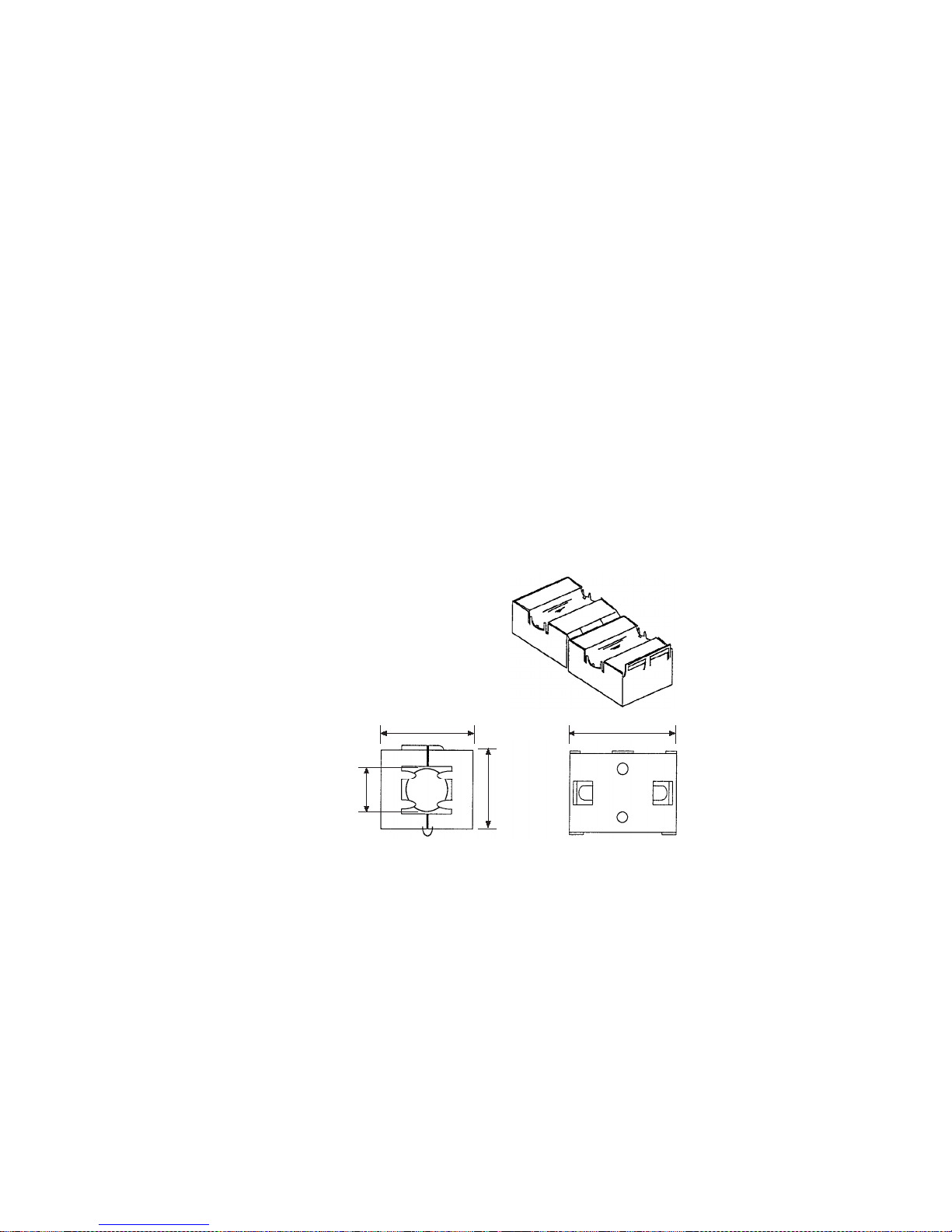
1,2,3... 1. Noise from the communications cable can be reduced by installing a ferrite
core on the communications cable within 10 cm of the DeviceNet Unit.
Ferrite Core (Data Line Filter): 0443-164151 (manufactured by Fair-Rite Products Co., Ltd.)
Impedance specifications
25 MHz: 105
Ω
100 MHz: 190 Ω
30 mm
13 mm
29 mm
33 mm
2. Wire the control panel with as thick and short electric lines as possible and
ground to 100
Ω min.
3. Keep DeviceNet communications cables as short as possible and ground
to 100
Ω min.
30 mm
13 mm 29 mm
33 mm
Page 13

xiv
The manuals related to the EJ1 DeviceNet Communications Unit are configured as shown in the following tables. Refer to these manuals as required.
■ EJ1
■ DeviceNet Master Unit
■ G3ZA Multi-channel Power Controller Manual
Related Manuals
Name Cat. No. Contents
EJ1
EJ1N-HFU@-DRT
DeviceNet Communications Unit Operation Manual
H155 (This
manual)
Describes the following information on the
DeviceNet Communications Unit.
• Overview and features
• System configuration
• Mounting and wiring
• Troubleshooting
EJ1
EJ1N-TC2@
EJ1N-TC4@
EJ1C-EDU@
Modular Temperature Controller User's Manual
H142 Describes the following information on the EJ1.
• Overview and features
• System configuration
• Mounting and wiring
• Troubleshooting
CX-Thermo Ver. 4.@ (online help)
EST2-2C-MV4
--(Available only
as online
help.)
Describes how to set parameters and adjust
devices (i.e., components such as Temperature
Controllers) using the CX-Thermo.
Name Cat. No. Contents
DeviceNet
Operation Manual
W267 Describes the configuration and construction of a
DeviceNet network, including installation procedures and specifications for cables, connectors,
and other connection devices, as well as information on the communications power supply.
DeviceNet Master Units
Operation Manual
W379 Describes the models, specifications, functions,
and application methods of C200HX/HG/HE,
CVM1, and CV-series DeviceNet Master Units.
CS1 Series DeviceNet Unit Operation Manual W380 Describes the models, specifications, functions,
and application methods of the CS1-series
DeviceNet Unit.
Name Cat. No. Contents
G3ZA
G3ZA-4H203-FLK-UTU
G3ZA-4H403-FLK-UTU
G3ZA-8H203-FLK-UTU
G3ZA-8H403-FLK-UTU
Multi-channel Power Controller User's Manual
Z200 Provides an outline of and describes the features,
installation, wiring, RS-485 serial communications
settings, and basic function for the G3ZA Multichannel Power Controller.
Page 14

xv
■ G3PW Power Controller Manual
■ CS/CJ-series PLC Manuals
■ Support Software Manuals
Name Cat. No. Contents
G3PW-A220EC-C-FLK
G3PW-A230EC-C-FLK
G3PW-A245EC-C-FLK
G3PW-A260EC-C-FLK
G3PW-A220EC-S-FLK
G3PW-A230EC-S-FLK
G3PW-A245EC-S-FLK
G3PW-A260EC-S-FLK
Power Controller User's Manual
Z280 Provides an outline of and describes the features,
installation, wiring, RS-485 serial communications
settings, and basic function for the G3PW Power
Controller.
Name Cat. No. Contents
SYSMAC CJ Series
CJ2H-CPU@@-EIP
CPU Unit Hardware Manual
W472 Provides an outlines of and describes the design,
installation, maintenance, and other basic operations for the CJ-series PLCs.
SYSMAC CJ2- Series
CJ2H-CPU@@-EIP
CPU Unit Software Manual
W473 Describes programming and other methods to use
the functions of the CJ-series PLCs.
SYSMAC CJ Series
CJ1G-CPU@@, CJ1M-CPU@@, CJ1G-CPU@@P,
CJ1G/H-CPU@@H, NSJ@-@@@@(B)-G5D,
NSJ@-@@@@(B)-M3D
Programmable Controllers Operation Manual
W393 Provides an outlines of and describes the design,
installation, maintenance, and other basic operations for the CJ-series PLCs.
SYSMAC CS/CJ Series
CS1G/H-CPU@@-EV1, CS1G/H-CPU@@H, CS1DCPU@@H, CS1D-CPU@@S, CJ1G-CPU@@, CJ1MCPU@@, CJ1G-CPU@@P, CJ1G/H-CPU@@H,
NSJ@-@@@@(B)-G5D, NSJ@-@@@@(B)-M3D
Programmable Controllers Programming Manual
W394 Describes programming and other methods to use
the functions of the CS/CJ-series PLCs.
SYSMAC CS/CJ Series
CS1G/H-CPU@@-EV1, CS1G/H-CPU@@H, CS1DCPU@@H, CS1D-CPU@@S, CJ2H-CPU@@-EIP,
CJ1G-CPU@@, CJ1M-CPU@@, CJ1G-CPU@@P,
CJ1G/H-CPU@@H, NSJ@-@@@@(B)-G5D, NSJ@-
@@@@(B)-M3D
Programmable Controllers Instructions Reference
Manual
W474 Describes the ladder diagram programming
instructions supported by CS/CJ-series PLCs.
SYSMAC CS Series
CS1G/H-CPU@@-EV1, CS1G/H-CPU@@H
Programmable Controllers Operation Manual
W339 Provides an outlines of and describes the design,
installation, maintenance, and other basic operations for the CS-series PLCs.
Name Cat. No. Contents
DeviceNet Configurator Ver. 2.@ Operation Manual W382 Describes the operating procedures of the
DeviceNet Configurator.
CXONE-AL@@C-EV3/AL@@D-EV3
CX-One Ver. 3.0 FA Integrated Tool Package Setup
Manual
W463 Installation and overview of CX-One FA Integrated
Tool Package.
CXONE-AL@@C-EV3/ CXONE-AL@@D-EV3
CX-Integrator Ver. 3.0 Operation Manual
W464 Describes operating procedures for the CX-Inte-
grator Network Configuration Tool for CS-, CJ-,
CP-, and NSJ-series Controllers.
SYSMAC WS02-CXPC1-E-V70
CX-Programmer Operation Manual
W446 Provides information on how to use the CX-Pro-
grammer for all functionality except for function
blocks.
Page 15

xvi
Meanings of Abbreviations and Terms
The following abbreviations and terms are used in this manual.
Note “EU” stands for Engineering Unit. EU is used as the minimum unit for engineering units such as
°C, m, and g. The size of EU varies according to the input type.
For example, when the input temperature setting range is –200 to +1300
°C, 1 EU is 1°C, and
when the input temperature setting range is –20.0 to +500.0
°C, 1 EU is 0.1°C.
For analog inputs, the size of EU varies according to the decimal point position of the scaling setting, and 1 EU becomes the minimum scaling unit.
Abbreviation
or term
Meaning
AT Autotuning
EDU EJ1 End Unit
EU Engineering unit (See note.)
HB Heater burnout
HS Heater short
LBA Loop burn alarm
LSP Local SP
OC Heater overcurrent
PV Process value
RSP Remote SP
SP Set point
TC4/TC2 EJ1 Basic Unit
• TC4: Four-channel Basic Unit
• TC2: Two-channel Basic Unit
Temperature
Controller
EJ1 Basic Unit listed above (TC4 or TC2)
Configurator Device to perform system setup and other functions. Includes functions for
reading ID data, reading and writing parameters, and displaying network
configurations. The DeviceNet Configurator and the CX-Integrator (with the
same screen configuration as the DeviceNet Configurator) are available for
Units manufactured by OMRON.
word (CIO) Words allocated in the CIO Areas of the CPU Unit of the PLC.
channel (ch) Number of control loops for a Temperature Controller.
communications unit number
An identification number for a Temperature Controller connected to a
DeviceNet Communications Unit. (Set using both rotary switch 1 and DIP
switch pin 2.)
unit number as
a CPU Bus Unit
The unit number of a DeviceNet Master Unit in the PLC. (Unit numbers are
used as identification numbers for CPU Bus Units.)
Page 16

xvii
TABLE OF CONTENTS
SECTION 1
Overview . . . . . . . . . . . . . . . . . . . . . . . . . . . . . . . . . . . . . . . . . 1
1-1 Features and System Configuration. . . . . . . . . . . . . . . . . . . . . . . . . . . . . . . . . . . . . . . . . . . . 2
1-2 Specifications. . . . . . . . . . . . . . . . . . . . . . . . . . . . . . . . . . . . . . . . . . . . . . . . . . . . . . . . . . . . . 9
1-3 Connecting Temperature Controllers. . . . . . . . . . . . . . . . . . . . . . . . . . . . . . . . . . . . . . . . . . . 11
1-4 Initial Temperature Controller Settings . . . . . . . . . . . . . . . . . . . . . . . . . . . . . . . . . . . . . . . . . 13
SECTION 2
Operating Procedures. . . . . . . . . . . . . . . . . . . . . . . . . . . . . . . 15
2-1 Setup Procedure. . . . . . . . . . . . . . . . . . . . . . . . . . . . . . . . . . . . . . . . . . . . . . . . . . . . . . . . . . . 16
2-2 Startup Procedure. . . . . . . . . . . . . . . . . . . . . . . . . . . . . . . . . . . . . . . . . . . . . . . . . . . . . . . . . . 17
SECTION 3
Parts, Installation, and Wiring . . . . . . . . . . . . . . . . . . . . . . . 21
3-1 Part Names and Functions . . . . . . . . . . . . . . . . . . . . . . . . . . . . . . . . . . . . . . . . . . . . . . . . . . .22
3-2 Installation . . . . . . . . . . . . . . . . . . . . . . . . . . . . . . . . . . . . . . . . . . . . . . . . . . . . . . . . . . . . . . . 27
3-3 DeviceNet Communications Cables Wiring . . . . . . . . . . . . . . . . . . . . . . . . . . . . . . . . . . . . . 30
3-4 Wiring the Temperature Controllers . . . . . . . . . . . . . . . . . . . . . . . . . . . . . . . . . . . . . . . . . . . 33
SECTION 4
Remote I/O Communications . . . . . . . . . . . . . . . . . . . . . . . . 35
4-1 Allocation Method Overview . . . . . . . . . . . . . . . . . . . . . . . . . . . . . . . . . . . . . . . . . . . . . . . . 36
4-2 Simple I/O Allocation . . . . . . . . . . . . . . . . . . . . . . . . . . . . . . . . . . . . . . . . . . . . . . . . . . . . . . 40
4-3 Allocating I/O from the Configurator . . . . . . . . . . . . . . . . . . . . . . . . . . . . . . . . . . . . . . . . . . 45
4-4 Expansion Remote I/O. . . . . . . . . . . . . . . . . . . . . . . . . . . . . . . . . . . . . . . . . . . . . . . . . . . . . . 68
4-5 Allocating Data in the Master . . . . . . . . . . . . . . . . . . . . . . . . . . . . . . . . . . . . . . . . . . . . . . . .73
4-6 Ladder Programming Examples . . . . . . . . . . . . . . . . . . . . . . . . . . . . . . . . . . . . . . . . . . . . . . 78
SECTION 5
Operations from the Configurator . . . . . . . . . . . . . . . . . . . . 83
5-1 List of Operations from the Configurator . . . . . . . . . . . . . . . . . . . . . . . . . . . . . . . . . . . . . . . 84
5-2 Operations from the Edit Device Parameters Window . . . . . . . . . . . . . . . . . . . . . . . . . . . . . 85
5-3 Maintenance Mode Window . . . . . . . . . . . . . . . . . . . . . . . . . . . . . . . . . . . . . . . . . . . . . . . . . 97
5-4 DeviceNet Communications Unit Monitor . . . . . . . . . . . . . . . . . . . . . . . . . . . . . . . . . . . . . . 102
SECTION 6
Explicit Message Communications . . . . . . . . . . . . . . . . . . . . 103
6-1 Overview of Explicit Message Communications . . . . . . . . . . . . . . . . . . . . . . . . . . . . . . . . . 104
6-2 Sending CompoWay/F Commands to a Temperature Controller . . . . . . . . . . . . . . . . . . . . . 108
6-3 Examples Using CompoWay/F Commands . . . . . . . . . . . . . . . . . . . . . . . . . . . . . . . . . . . . . 112
6-4 Example of Sending Explicit Messages . . . . . . . . . . . . . . . . . . . . . . . . . . . . . . . . . . . . . . . . 118
6-5 Sending Explicit Messages . . . . . . . . . . . . . . . . . . . . . . . . . . . . . . . . . . . . . . . . . . . . . . . . . .119
Page 17

xviii
TABLE OF CONTENTS
SECTION 7
Communications Performance . . . . . . . . . . . . . . . . . . . . . . . 125
7-1 Remote I/O Communications Characteristics . . . . . . . . . . . . . . . . . . . . . . . . . . . . . . . . . . . . 126
7-2 Message Communications Characteristics . . . . . . . . . . . . . . . . . . . . . . . . . . . . . . . . . . . . . . 134
SECTION 8
Troubleshooting and Maintenance . . . . . . . . . . . . . . . . . . . . 137
8-1 Indicators and Error Processing. . . . . . . . . . . . . . . . . . . . . . . . . . . . . . . . . . . . . . . . . . . . . . . 138
8-2 Maintenance. . . . . . . . . . . . . . . . . . . . . . . . . . . . . . . . . . . . . . . . . . . . . . . . . . . . . . . . . . . . . . 139
Appendices
A Connecting to a Master from Another Company . . . . . . . . . . . . . . . . . . . . . . . . . . . . . . . . . 145
B Allocation Numbers for Configurators Manufactured by Other Companies . . . . . . . . . . . . 151
C List of Connectable Devices . . . . . . . . . . . . . . . . . . . . . . . . . . . . . . . . . . . . . . . . . . . . . . . . . 171
Index. . . . . . . . . . . . . . . . . . . . . . . . . . . . . . . . . . . . . . . . . . . . . 175
Revision History . . . . . . . . . . . . . . . . . . . . . . . . . . . . . . . . . . . 179
Page 18

xix
About this Manual:
This manual describes the installation and operation of the EJ1 DeviceNet Communications Unit for
EJ1 Temperature Controllers and includes the sections described below.
Please read this manual carefully and be sure you understand the information provided before
attempting to install or operate the EJ1 DeviceNet Communications Unit. Be sure to read the precautions provided in the following section.
Precautions provides general precautions for using the EJ1 DeviceNet Communications Unit, Programmable Controller, and related devices.
Section 1 introduces the features and system configuration of the EJ1 DeviceNet Communications
Unit, the types of EJ1 Temperature Controller that can be used, and other basic information.
Section 2 outlines the basic operating procedures of the EJ1 DeviceNet Communications Unit.
Section 3 describes the methods used to install and wire the EJ1 DeviceNet Communications Unit
and the EJ1 Temperature Controller. The settings of DeviceNet Communications Unit switches are
also described.
Section 4 describes the input (IN) areas and output (OUT) areas that EJ1 DeviceNet Communications
Units can use for remote I/O communications. The methods to allocate data for master communications are also described.
Section 5 describes the DeviceNet Configurator operations that can be used for the EJ1 DeviceNet
Communications Unit except for allocation procedures, which are described in SECTION 4 Remote I/O
Communications.
Section 6 describes how to send explicit messages to the EJ1 DeviceNet Communications Unit,
including how to send CompoWay/F commands using explicit messages. CompoWay/F commands
are supported by the EJ1 Temperature Controller.
Section 7 provides information on the time required for a complete communications cycle, for an output response to be made to an input, to start the system, and to send messages.
Section 8 describes error processing, periodic maintenance operations, and troubleshooting procedures needed to keep the DeviceNet Network operating properly. Details on resetting replaced Units
are also provided. Read through the error processing procedures in both this manual and the operation
manual for the DeviceNet master being used before operation so that operating errors can be identified
and corrected more quickly.
The Appendices provide the handling methods for EDS setting files required for multivendor environments, the device profile of the EJ1 DeviceNet Communications Unit, and information on related products.
!WARNING Failure to read and understand the information provided in this manual may result in per-
sonal injury or death, damage to the product, or product failure. Please read each section
in its entirety and be sure you understand the information provided in the section and
related sections before attempting any of the procedures or operations given.
Page 19

xx
Page 20

1
SECTION 1
Overview
This section introduces the features and system configuration of the EJ1 DeviceNet Communications Unit, the types of EJ1
Temperature Controller that can be used, and other basic information.
1-1 Features and System Configuration . . . . . . . . . . . . . . . . . . . . . . . . . . . . . . . . 2
1-1-1 Features. . . . . . . . . . . . . . . . . . . . . . . . . . . . . . . . . . . . . . . . . . . . . . . 2
1-1-2 Overview of Unit Communications Functions. . . . . . . . . . . . . . . . . 4
1-1-3 System Configuration . . . . . . . . . . . . . . . . . . . . . . . . . . . . . . . . . . . . 7
1-2 Specifications . . . . . . . . . . . . . . . . . . . . . . . . . . . . . . . . . . . . . . . . . . . . . . . . . 9
1-2-1 DeviceNet Communications Specifications . . . . . . . . . . . . . . . . . . . 9
1-2-2 Function and Performance Specifications . . . . . . . . . . . . . . . . . . . . 10
1-2-3 General Specifications . . . . . . . . . . . . . . . . . . . . . . . . . . . . . . . . . . . 11
1-3 Connecting Temperature Controllers . . . . . . . . . . . . . . . . . . . . . . . . . . . . . . . 11
1-3-1 Temperature Controller ID and Number of Connectable Units . . . . 11
1-3-2 Temperature Controller Communications . . . . . . . . . . . . . . . . . . . . 12
1-3-3 Temperature Controller Models . . . . . . . . . . . . . . . . . . . . . . . . . . . . 12
1-3-4 Temperature Controller Power Supply . . . . . . . . . . . . . . . . . . . . . . . 12
1-3-5 Temperature Controller Registration . . . . . . . . . . . . . . . . . . . . . . . . 12
1-4 Initial Temperature Controller Settings. . . . . . . . . . . . . . . . . . . . . . . . . . . . . . 13
Page 21

2
Features and System Configuration Section 1-1
1-1 Features and System Configuration
1-1-1 Features
The DeviceNet Communications Unit enables a DeviceNet master to communicate with multiple EJ1 Temperature Controllers through the DeviceNet to
monitor their process values, write parameters, and control operation.
Using DeviceNet Functions
Simultaneously Managing
Multiple Temperature
Controllers from the
Master
Up to 16 Temperature Controllers can be connected to a single DeviceNet
Communications Unit. The DeviceNet Communications Unit is connected to
the master as a DeviceNet slave. Up to 63 slaves can be connected to a single master, so multiple DeviceNet Communications Units and other types of
slaves can be managed as part of the same system.
Remote I/O
Communications
The master and DeviceNet Communications Units can share I/O by using
remote I/O communications. Data in the EJ1 Temperature Controllers, such
as process values (PVs) and set points (SPs), can be allocated for communications with the master to enable sending and receiving the allocated data via
remote I/O communications, without requiring special programming.
• Remote I/O Communications without a Configurator
Using the DeviceNet Communications Unit, basic Temperature Controller
data can be allocated for communications with the master, such as process values (PVs) and set points (SPs), without requiring a Configurator.
This is called “simple I/O allocation.” Simple I/O allocation can be easily
set from the DIP switch of the DeviceNet Communications Unit.
• User-set Data Allocations with a Configurator
The specific data required for communications with the master can also
be allocated by using I/O allocations from the Configurator.
Expansion Remote I/O to
Enable Using More Than
100 Words of Parameters
Expansion remote I/O can be used to read and write parameters. Specific
parameters allocated in I/O memory of the master can be switched to a variety of parameters by using memory operations. This function enables manipulating more than 100 words of parameters. Even if the number of parameters
to be read and written increases, modifications can be handled simply by
changing operations in the memory of the master.
Explicit Message
Communications
By executing commands from the PLC, various operations can be performed,
including reading/writing specific parameters, such as reading process values
or writing set points, and performing operations using operation commands.
CompoWay/F communications commands can also be executed using explicit
message communications.
Setting, Monitoring, and
Operating the
Temperature Controller
from the Configurator
The Configurator (Ver. 2.2 or higher) or CX-Integrator (Ver. 2.2 or higher) can
be used to create the device parameters for the DeviceNet Communications
Unit, including settings for the DeviceNet Communications Unit and setting for
the Temperature Controllers. The Configurator can then be used to download
the parameters together to the DeviceNet Communications Unit and Temperature Controllers. (See note.)
The Configurator can also be used to monitor Temperature Controller process
values, and execute operation commands for the Temperature Controllers.
The Configurator can be used to copy parameters between Temperature Controller channels, allowing the initial parameters of Temperature Controllers
requiring the same or similar parameters to be easily set.
Page 22

3
Features and System Configuration Section 1-1
Automatically Detects
Baud Rate
Previously, the baud rate had to be set for each slave, but the DeviceNet Communications Unit automatically detects and matches the baud rate of the master, so this setting is not required. (If the master's baud rate is changed, turn
OFF the communications power supply to the DeviceNet Communications
Unit and then turn it ON again.)
Wide Range of Maintenance Functions
Copy Function (Uploading
or Downloading
Temperature Controller
Parameters)
Parameters for all Temperature Controllers connected to the DeviceNet Communications Unit can be uploaded or downloaded together. (The parameters
that have been read are stored in the DeviceNet Communications Unit except
for bank parameters and G3ZA and G3PW parameters.) When Temperature
Controllers are replaced, the new Controllers can be easily reset onsite without using a Configurator.
Monitoring Network Power
Volt age
The DeviceNet network communications power voltage values (present value,
peak value, and bottom value) can be stored in the DeviceNet Communications Unit, and the recorded voltages can be read from the Configurator. By
setting the voltage monitor value in the DeviceNet Communications Unit, notification will be sent to the master if the voltage level drops below the monitor
value.
Monitoring the Unit
Conduction Time
The conduction time of the DeviceNet Communications Unit's internal circuit
power supply can be recorded. The recorded conduction time can be read
from the Configurator or using explicit messages. By setting a monitor value
for the conduction time in the DeviceNet Communications Unit, notification will
be sent to the master when the total time exceeds the monitor value.
Unit Comments Any name can be set for a DeviceNet Communications Unit and recorded in
the Unit. Specifying names enables the user to easily differentiate the applications of the DeviceNet Communications Units when setting and monitoring
them from the Configurator.
Setting Temperature
Controller Comments
A name can be set for each Temperature Controller channel connected to the
DeviceNet Communications Unit and recorded in the DeviceNet Communications Unit. Specifying names enables the user to easily differentiate the function of each channel when setting and monitoring them from the Configurator.
Monitoring
Communications Error
History
The error status for the last four communications errors (the causes and communications power voltage when the communications error occurred) can be
recorded in the DeviceNet Communications Unit. The recorded communications error history can be read from the Configurator.
Monitoring Temperature
Controller Power Status
The power supply to the Temperature Controllers can monitored to confirm
that power is ON and send notification of the status to the master. (The power
status can be checked for Temperature Controllers connected to the
DeviceNet Communications Unit only.) The power status of the Temperature
Controllers can be read from the Configurator or using explicit messages.
Monitor Temperature
Controller Conduction
Time and RUN Time
The conduction time of the Temperature Controller's internal circuit power
supply or the RUN time of the Temperature Controller can be totaled and
recorded. (Select whether to total the conduction time or RUN time by setting
the monitor mode.) The recorded total time can be read using the Configurator or explicit messages. By setting a monitor value in the DeviceNet Communications Unit, notification will be sent to the master if the Unit conduction time
exceeds the monitor value.
Page 23
4
Features and System Configuration Section 1-1
1-1-2 Overview of Unit Communications Functions
Remote I/O
Communications
DeviceNet Communications Unit data is shared with the master's IN Area and
OUT Area through DeviceNet. Up to 100 words (200 bytes) each can be used
as the IN Area and OUT Area for the DeviceNet Communications Unit. (The
first word (two bytes) of the OUT Area is always allocated for the OUT Enable
Bit).
The IN Area is allocated for data such as the communications status and the
process values of the Temperature Controller channels and the OUT Area is
allocated for the set points of the channels and other data.
When using a CS/CJ-series DeviceNet Unit as the master, the IN Area can be
divided into two areas. One is normally used for input data (such as Temperature Controller process values), and the other can be used for reading status
(such as Temperature Controller status). Even when the IN Area is divided
into two areas, however, the total number of words that can be used for the IN
Area is still 100 words (200 bytes).
DeviceNet Communications Unit
DeviceNet
PLC
CPU Unit
Output Enable Bit
Read parameter setting
Write parameter setting
Unit 0, ch 1 PV
Unit 0, ch 2 PV
Unit 1, ch 1 PV
Input Area
Unit 0 Unit 1
Temperature Controllers
Remote I/O communications
output area
Remote I/O
communications
DeviceNet Communications Unit
Unit 0, ch 1 SP
Unit 0, ch 2 SP
Unit 1, ch 1 SP
Output Completed Flags
Read parameter monitor
Page 24
5
Features and System Configuration Section 1-1
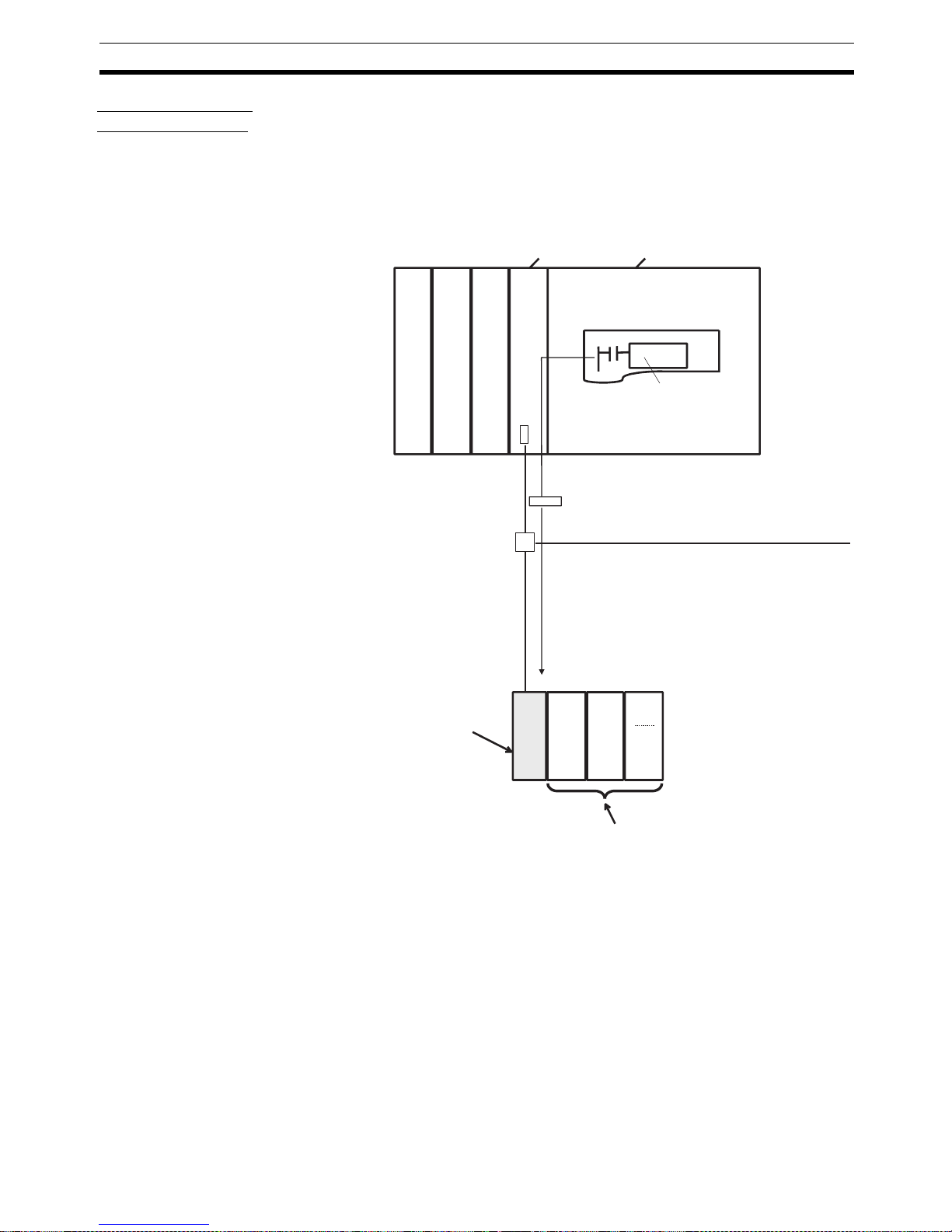
Explicit Message
Communications
Explicit message commands can be sent from the master to the DeviceNet
Communications Unit to read or write the parameters of the connected Temperature Controllers. CompoWay/F communications commands that were
previously used for Temperature Controllers can also be sent (in explicit message format).
The DeviceNet Communications Unit's own parameters can also be read or
written.
DeviceNet
PLC
DeviceNet Unit CPU Unit
Ladder program
Explicit message communications
Unit 0 Unit 1
Temperature Controllers
CMND or other
communications
instruction
DeviceNet Communications Unit
Page 25
6
Features and System Configuration Section 1-1
Transferring, Monitoring, and Operating from the Configurator
Any of the Temperature Controller parameters can be read or written from a
personal computer using the Configurator (Ver. 2.44 or higher) or CX-Integrator (Ver. 2.2 or higher) and then saved as a file.
The setup parameters for each Temperature Controller channel can be copied, allowing the same or similar settings to be easily set for multiple Temperature Controllers.
EJ1
CS/CJ-series DeviceNet Unit
DeviceNet Configurator
PLC
DeviceNet
Temperature Controllers
DeviceNet Slave
Serial connection
Setting, monitoring, and executing operation commands for the
Temperature Controllers using the Configurator.
• Setting Temperature Controller settings and downloading them.
• Monitoring Temperature Controller process values and target values.
• Executing Temperature Controller operation commands.
DeviceNet Communications Unit
Unit 0Unit
1
Page 26
7
Features and System Configuration Section 1-1
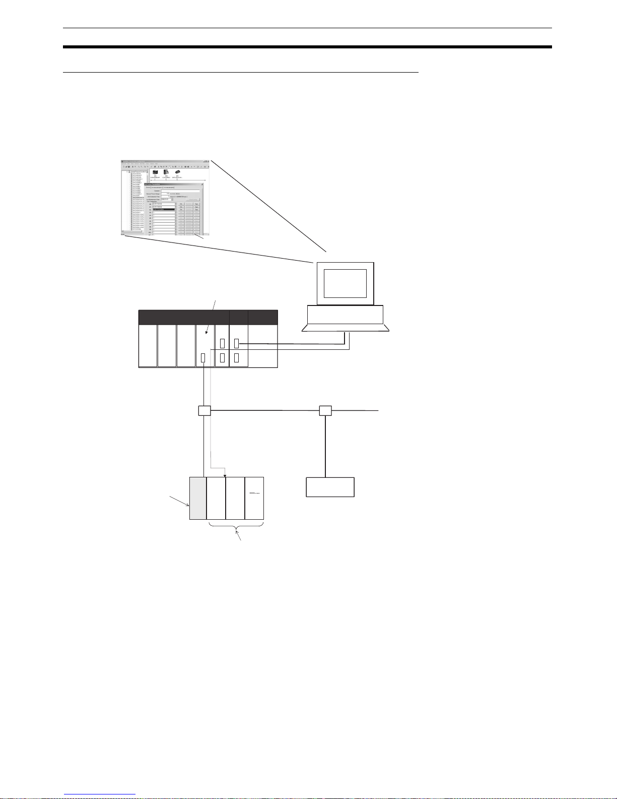
1-1-3 System Configuration
Basic Configuration
Connect the master to the DeviceNet Communications Unit, and connect the
DeviceNet Communications Unit to the Temperature Controllers.
The DeviceNet Communications Unit shares I/O with the master as a
DeviceNet slave, and can send data to and receive data from the master
using explicit messages.
Up to 63 slaves can be connected to a single master. Up to 16 Temperature
Controllers can be connected to a single DeviceNet Communications Unit.
Note Always connect the DeviceNet Communications Unit to the Temperature Con-
trollers on the left end of the block.
DeviceNet
PLC
CS/CJ-series DeviceNet Unit
DeviceNet Configurator
Serial connection
(setting, monitoring, and operating)
Explicit messages
EDU
DeviceNet Communications Unit
Temperature Controllers (up to
16 Controllers) (See note.)
10
1
NODE
ADR
EJ1N
DRT
COPY
EDS
UP/DN
TC2/4
MODE
MAX
No.
MS
NS
TS
1
0
9
8
7
6
5
4
3
2
1
0
9
8
7
6
5
4
3
2
4
5
6
7
8
9
A
B
D
E
F
0
1
2
3
C
NO
123456
RS-485 (CompoWay/F)
Distributed placement
of 16th Temperature Controlle
r
Connect
to port B
DeviceNet slave
Note: Up to 16 Temperature Controllers can be connected to one
DeviceNet Communications Unit. Use distributed placement
via RS-485 for the 16th Temperature Controller.
Page 27
8
Features and System Configuration Section 1-1
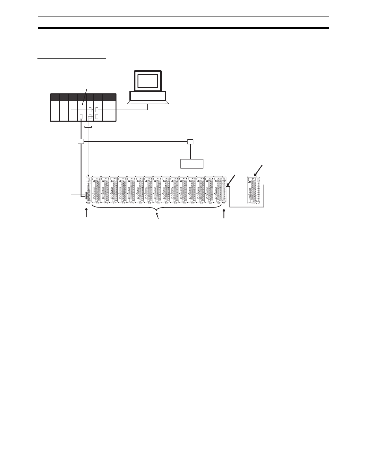
Distributed Placement
Connect the master and DeviceNet Communications Unit to port B (RS-485)
of each End Unit.
The total cable length for RS-485 communications can be up to 500 m, so
Temperature Controllers located at a distance can be operated using a single
DeviceNet Communications Unit.
Up to 63 slaves can be connected to a single master. Up to 16 Temperature
Controllers total for all blocks can be connected to a single DeviceNet Communications Unit.
DeviceNet
CS/CJ-series DeviceNet Unit
DeviceNet Configurator
Serial connection
Explicit messages
DeviceNet slave
(setting, monitoring, and operating)
DeviceNet Communications
Unit
Temperature Controllers (up to
16 Controllers)
Connect to port
B on the EDU
10
1
NODE
ADR
EJ1N
DRT
COPY
EDS
UP/DN
TC2/4
MODE
MAX
No.
MS
NS
TS
1
0
9
8
7
6
5
4
3
2
1
0
9
8
7
6
5
4
3
2
4
5
6
7
8
9
A
B
D
E
F
0
1
2
3
C
NO
123456
PLC
RS-485 communications cable
(length: 500 m max.)
Connect to port
B on the EDU
Connect to port
B on the EDU
Connect to port
B on the EDU
Page 28

9
Specifications Section 1-2
Terminating resistance of 100 to 125 Ω (1/2 W) must be connected to both
ends of the RS-485 communications transmission path.
Note Connect the DeviceNet Communications Unit to the Temperature Controllers
on the left end of any one of the blocks.
1-2 Specifications
1-2-1 DeviceNet Communications Specifications
Item Specifications
Communications protocol Conforms to DeviceNet
Communications
functions
Remote I/O communications
• Master-slave connections (polling, COS, or cyclic)
• Conform to DeviceNet specifications.
Simple I/O allocation
• Allocates I/O data using switch settings only, without a Configurator.
• I/O is allocated for Temperature Controller status, process values, set points,
alarm output status, and other basic data only.
• One block for IN Area, up to 86 words (words are allocated through the unit
number set in the highest communications unit number setting)
• One block for OUT Area, up to 74 words (words are allocated through the unit
number set in the highest communications unit number setting)
I/O allocations
from the Configurator
• Can be used to allocate any I/O data from the Configurator.
• Can be used to allocate any data, such as parameters specific to the
DeviceNet Communications Unit and the Temperature Controller variable area.
• Up to 2 blocks for the IN Area, up to a total of 100 words. (See note 1.)
• One block for OUT Area 1 block, up to 100 words (the first word is always allocated to the OUT Enable Bit). (See note 2.)
Message communications
• Explicit message communications
• CompoWay/F communications commands can be sent (commands are sent in
explicit message format).
Setting, monitoring
and controlling
operations from
the Configurator
Supported by DeviceNet Configurator (using the Edit Parameters and Device
Monitor functions of the DeviceNet Communications Unit and Temperature Controllers).
• Used to set and monitor the DeviceNet Communications Unit.
• Used to register connection configurations, make initial settings (see note 3),
change settings, and monitor the Temperature Controllers.
• Use to allocates data for master communications.
• Used to allocates word in the IN and OUT Areas for specific data.
• Used to sends operation commands to the Temperature Controllers.
Connection format Combination of multidrop and T-branch connections (for trunk and drop lines)
Baud rate DeviceNet: 500, 250, or 125 kbps, or automatic detection of master baud rate
Communications media Special 5-wire cable (2 signal lines, 2 power lines, and 1 shield line)
Communications distance Baud rate Network length Drop line length Total drop line
length
500 kbps 100 m max.
(100 m max.)
6 m max. 39 m max.
250 kbps 250 m max.
(100 m max.)
6 m max. 78 m max.
125 kbps 500 m max.
(100 m max.)
6 m max. 156 m max.
The values in parentheses apply when Thin Cables are used.
Communications power supply 11 to 25 VDC
Maximum number of nodes that can be
connected
64 (includes Configurator when used.)
Maximum number of slaves that can be
connected
63
Page 29

10
Specifications Section 1-2
Note 1. When a CS/CJ-series DeviceNet Unit is used as the master, two blocks
can be used for the IN Area (the connections can also be set). When a
CVM1, CV-series, or C200HX/HG/HE DeviceNet Master Unit is used, the
IN Area must be in 1 block, and up to 100 words (200 bytes) are allocated.
(Only polling connections can be used.)
2. When a CVM1, CV-series, or C200HX/HG/HE DeviceNet Master Unit is
used, up to 32 words can be allocated in the master for a single node.
3. The set points, alarm setting values, PID constants, and other Temperature Controller parameters can be set together.
1-2-2 Function and Performance Specifications
Error control CRC error detection
Power supply Power supplied from DeviceNet communications connector (DeviceNet commu-
nications power supply and DeviceNet Communications Unit internal circuit
power supply)
Item Specifications
Item Specifications
Maximum number of Temperature
Controllers that can be connected
16
Note Up to 15 Units can be connected side by side. The 16th Unit is connected
using distributed placement by using an End Unit.
Applicable Temperature Controllers
(TC4)
•EJ1N-TC4A-QQ
•EJ1N-TC4B-QQ
(TC2)
• EJ1N-TC2A-QNHB
• EJ1N-TC2B-QNHB
• EJ1N-TC2A-CNB
• EJ1N-TC2B-CNB
Power supply Power is supplied via the terminal block of the End Unit (power supply for communi-
cations between the DeviceNet Communications Unit and Temperature Controllers
and power supply for internal circuits of the Temperature Controllers).
Copying The parameters of a connected Temperature Controller can be uploaded or down-
loaded as a batch by using the DeviceNet Communications Unit’s DIP switch or an
explicit message. The bank, G3ZA, and G3PW parameters are not copied.
The uploaded parameters are stored in the DeviceNet Communications Unit.
Page 30
11
Connecting Temperature Controllers Section 1-3
1-2-3 General Specifications
1-3 Connecting Temperature Controllers
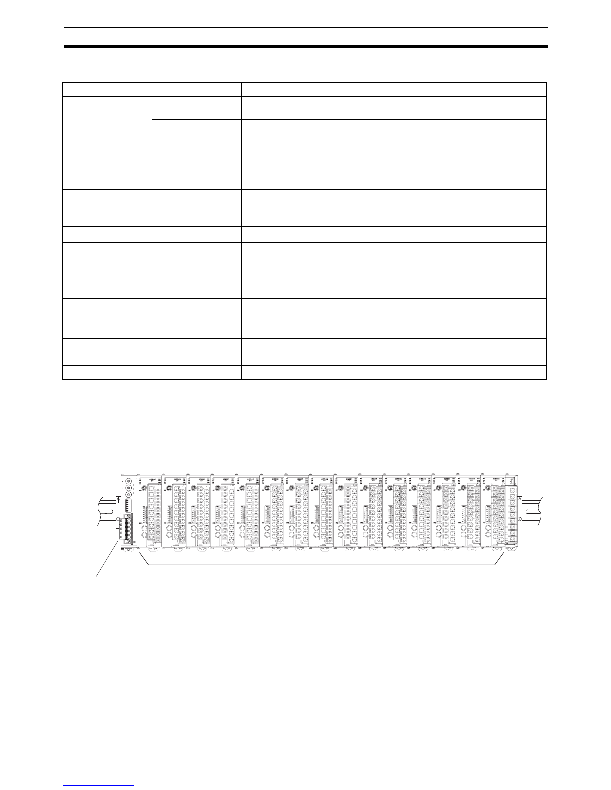
1-3-1 Temperature Controller ID and Number of Connectable Units
A DeviceNet Communications Unit is connected as shown in the following diagram.
The DeviceNet Communications Unit differentiates each of the connected
Temperature Controllers according to communications unit numbers (0 to F: 0
to 15 decimal). The Temperature Controllers can be connected in any order.
The communications unit number of each Temperature Controller is set using
the rotary switch on the front panel of the Temperature Controller. Always set
a unique communications unit number for each Temperature Controller.
Up to 15 Temperature Controllers can be connected side by side. By using an
End Unit, however, up to 16 Temperature Controller can be connected using
distributed placement.
Item Specifications
Supply voltage DeviceNet power
supply
24 VDC (internal circuit)
External input power
supply
24 VDC (for RS-485 communications circuit/ Temperature Controllers)
Allowable voltage
range
DeviceNet power
supply
11 to 25 VDC
External input power
supply
20.4 to 26.4 VDC
Power consumption (at maximum load) 1 W max.
Current consumption (DeviceNet power
supply)
45 mA max. (24 VDC)
Vibration resistance
10 to 55 Hz, 10m/s2 for 2 hours each in X, Y, and Z directions
Shock resistance
150m/s
2
max. 3 times each in 3 axes, 6 directions
Dielectric strength 600 VAC 50 or 60 Hz 1min
Insulation resistance 20 MΩ min. (at 100 VDC)
Ambient temperature −10 to 55°C (with no condensation or icing)
Ambient humidity 25% to 85%
Storage temperature −25 to 65°C (with no condensation or icing)
Enclosure rating IP20
Dimensions 20 × 90 × 65 mm (W × H × D)
Memory protection EEPROM, 100,000 write operations (backup data)
Weight 70 g max.
Temperature Controllers
DeviceNet
Communications Unit
10
1
NODE
ADR
EJ1N
DRT
COPY
EDS
UP/DN
TC2/4
MODE
MAX
No.
MS
NS
TS
1
0
9
8
7
6
5
4
3
2
1
0
9
8
7
6
5
4
3
2
4
5
6
7
8
9
A
B
D
E
F
0
1
2
3
C
NO
123456
Page 31

12
Connecting Temperature Controllers Section 1-3
Note There is no priority between operation commands and settings for DeviceNet
communications from the master, and operation commands and settings from
the Configurator. Do not change the same data or send different operation
commands more than one source at the same time.
1-3-2 Temperature Controller Communications
The DeviceNet Communications Unit communicates through port B on the
Temperature Controllers. The DeviceNet Communications Unit will automatically set the communications settings. You do not need to set them. If you
mistakenly change the settings, use the CX-Thermo to restore the default settings and then reset the DeviceNet Communications Unit.
1-3-3 Temperature Controller Models
Refer to EJ1 Temperature Controllers on page 171 for information on the
Temperature Controller models.
1-3-4 Temperature Controller Power Supply
Power is supplied to the Temperature Controllers through the End Unit. For
details, refer to the EJ1 Modular Temperature Controller User's Manual (Cat.
No. H142).
1-3-5 Temperature Controller Registration
The connected Temperature Controllers must be registered in the configuration in the DeviceNet Communications Unit. The DeviceNet Communications
Unit automatically verifies that the registered the Temperature Controllers
match the Temperature Controllers currently able to communicate. If the unit
numbers do not match in the verification process, the Temperature Controllers
will be determined to have an error, causing the following status.
• The TS indicator will flash red.
• The Communicating Flag will turn OFF and the Communications Error
Flag will turn ON for each Temperature Controller that is not communicating but is registered as being connected to the DeviceNet Communications Unit.
The method used to register the connection configuration depends on the
method of remote I/O allocation.
1,2,3... 1. Allocation from the Configurator
With DIP switch pin 1 set to OFF, turn ON the power supply, and register
the configuration using the Configurator or an explicit message.
2. Allocation Using Simple Allocation
Turn DIP switch pin 1 to ON, set DIP switch pin 2 to the model to be connected, and set the highest communications unit number setting to the
highest communications unit number of the Temperature Controllers that
are connected.
Page 32

13
Initial Temperature Controller Settings Section 1-4
1-4 Initial Temperature Controller Settings
The following four methods are provided for setting the EJ1 Temperature Controllers.
Transferring Temperature Controller Parameters Together
Set each of the Temperature Controller parameters in the Edit Device Parameters Window from the DeviceNet Configurator, and then transfer them
together via the DeviceNet network.
Setting with Explicit
Messages
Set the initial settings from the PLC with the master by sending an explicit
message.
CS/CJ-series DeviceNet Unit
Configurator
Edit Unit parameters
PLC
DeviceNet
Proportional band
Target value
Edit device parameters
Temperature
Controller
parameters
DeviceNet
Communications Unit
CMND
CMND
PLC
(1) Execute a STOP command.
(Operation command 30 05, command code 0B, related data FF)
(2) Execute an AUTO command.
(Operation command 30 05, command code 0D, related data FF)
DeviceNet
Communications Unit
(3) Make initial settings.
(VARIABLE AREA WRITE 01 02, variable type E0 to F2)
Page 33

14
Initial Temperature Controller Settings Section 1-4
Page 34

15
SECTION 2
Operating Procedures
This section outlines the basic operating procedures of the EJ1 DeviceNet Communications Unit.
2-1 Setup Procedure . . . . . . . . . . . . . . . . . . . . . . . . . . . . . . . . . . . . . . . . . . . . . . . 16
2-2 Startup Procedure . . . . . . . . . . . . . . . . . . . . . . . . . . . . . . . . . . . . . . . . . . . . . . 17
2-2-1 Simple I/O Allocation. . . . . . . . . . . . . . . . . . . . . . . . . . . . . . . . . . . . 17
2-2-2 I/O Allocation Using the Configurator . . . . . . . . . . . . . . . . . . . . . . . 18
Page 35

16
Setup Procedure Section 2-1
2-1 Setup Procedure
Use the following procedure to prepare the DeviceNet Communications Unit
for use. Refer to the reference pages provided for detailed information on
each step.
Step Item Details Reference
page
1 Connect the DeviceNet Communi-
cations Unit and the Temperature
Controllers.
Connect the DeviceNet Communications Unit to the
Temperature Controllers. Attach the seal supplied with
the End Unit to the hole on the side of the DeviceNet
Communications Unit.
28
2 Mount the connected DeviceNet
Communications Unit and the Temperature Controllers to the DIN
Rail.
Mount the joined DeviceNet Communications Unit and
the Temperature Controllers to the DIN Rail. To ensure
secure mounting, always attach an End Plate to each
end.
28
3 Connect the RS-485 communica-
tions cable (only for distributed
placement).
When using a multiblock configuration for the Temperature Controllers connected to the DeviceNet Communications Unit, connect the RS-485 communications cable
to port B on the End Unit for each block.
8
4 Connect the power supply Connect a 24-VDC power supply to the power supply ter-
minals of the End Unit.
Note Do not turn ON the power supply at this time. This
power supply is used as the internal circuit power
supply of the Temperature Controllers and the
communications power supply between the
DeviceNet Communications Unit and the Temperature Controllers.
---
5 Wire the Temperature Controllers. Wire the Temperature Controller temperature inputs and
control outputs.
Note Do not turn ON the power supply at this time.
---
6 Set the communications unit num-
bers of the Temperature Controllers.
Set the communications unit number of each Temperature Controllers using the rotary switch and DIP switch
on the Temperature Controller. Set a unique communications unit number for each Temperature Controller.
---
7 Set the DeviceNet node address. Set the DeviceNet node address (0 to 63) of the
DeviceNet Communications Unit. Set the ten’s digit using
the ×10 rotary switch, and the one’s digit using the ×1
rotary switch. Set a unique node address for each slave
connected to the same master.
24
Page 36

17
Startup Procedure Section 2-2
2-2 Startup Procedure
2-2-1 Simple I/O Allocation
Use this method in the following situations.
• To allocate words in the master only for basic data, such as the set points
(SPs), process values (PVs), and alarm outputs for each Temperature
Controller.
• To use the DeviceNet Communications Unit without a Configurator (when
allocating only fixed I/O in the master).
Step Item Details Reference
page
8 Set the I/O allocation method. Set simple I/O allocation as the method for allocating I/O
data in the IN and OUT Areas used by the DeviceNet
Communications Unit. Turn ON pin 1 of the DIP switch.
Set DIP switch pin 2 to the model of the Temperature
Controller connected.
25
9 Set the highest unit number of the
connected Temperature Controllers.
Set the highest communications unit number of the Temperature Controllers connected to the DeviceNet Communications Unit using the rotary switch (Max. No.) of
the Unit. This setting will determine the size of the IN and
OUT Areas.
26
10 Connect the DeviceNet communi-
cations connectors.
Connect the DeviceNet communications connector to the
DeviceNet Communications Unit.
Note Do not turn ON the communications power sup-
ply at this time.
This power supply is also used as the internal circuit power supply of the DeviceNet Communications Unit.
32
11 Turn ON the power to the End Unit. Turn ON the power connected to the End Unit.
Note The Temperature Controllers will start.
---
12 Turn ON the DeviceNet communi-
cations power
(V+, V−).
Turn ON the communications power supply to the
DeviceNet Communications Unit. (See note.)
Note The DeviceNet Communications Unit will start.
---
13 Check the indicators on the
DeviceNet Communications Unit.
Check that the status of each indicator on the DeviceNet
Communications Unit is as follows:
MS: Operating normally when lit green.
NS: Operating normally when lit green. (DeviceNet
online or communications connected)
TS: Communicating with Temperature Controllers
when lit green.
23
14 Operate from the Configurator (if
user-set allocation is used at the
master).
Note This also applies if 11 or
more TC4 Units are connected.
With the Configurator online, open the master's Edit
Device Parameters Window and allocate the IN and OUT
Areas used by DeviceNet in the master. Click the Master
I/O Allocations Tab, specify the first words for allocation
input 1 and allocation output 1, and download the parameters to the master.
Note When fixed allocations are used, I/O is allocated
automatically.
73
Page 37

18
Startup Procedure Section 2-2
Note When changing the baud rate of the master after starting the DeviceNet Com-
munications Unit, turn ON the communications power supply of the DeviceNet
Communications Unit again, and restart the Unit.
2-2-2 I/O Allocation Using the Configurator
Use this method for any of the following situations.
• To select any parameters (such as PID constants) or status information,
apart from the Temperature Controller set points (SPs), process values
(PVs), or alarm outputs, and allocate words for them in the master (up to
100 words each in the IN Area and OUT Area).
• To allocate data in any order.
• To use remote I/O communications to allocate only data that is always
required in the master and not allocate unnecessary data.
Note Up to 100 words each can be allocated in the IN Area and OUT Area for
remote I/O communications. To read and write larger amounts of data, use the
following procedure.
• Use expansion remote I/O.
• Use explicit message communications. Also write data using explicit message communications for data that is written only when required.
• Use multiple DeviceNet Communications Units and distribute the number
of Temperature Controllers connected to each DeviceNet Communications Unit.
15 Start remote I/O communications. Enable the master's scan list and change the PLC to
RUN Mode.
Remote I/O communications will start, and the contents
of the IN and OUT Areas in the master and DeviceNet
Communications Unit will be synchronized.
---
Using explicit message communications
Send explicit messages from the master.
Explicit messages can be used to perform control and
monitoring that cannot be achieved using the IN and
OUT Areas alone, by sending explicit messages to the
DeviceNet Communications Unit.
104
16 Set the initial settings or monitor
the Temperature Controller.
With the Configurator online, perform Temperature Controller initial settings or monitoring from the Edit Device
Parameters Window for the DeviceNet Communications
Unit.
93
17 Upload the parameters of the Tem-
perature Controller to the
DeviceNet Communications Unit.
When the system has started normally, upload (backup)
all the parameters to the DeviceNet Communications
Unit in case of Temperature Controller malfunction. Creating a backup copy of the parameters will allow parameters to be easily reset onsite after a Temperature
Controller has been replaced, without requiring a Configurator.
Procedure: Turn OFF pin 3 of the DIP switch of the
DeviceNet Communications Unit, turn ON pin 6 (1 to
5 s), and then turn it OFF again.
25 and 141
Step Item Details Reference
page
Page 38

19
Startup Procedure Section 2-2
Step Item Details Reference
page
8 Set the method for allocating I/O. Set to the Configurator as the method for allocating I/O
data in the IN and OUT Areas used by the DeviceNet
Communications Unit. Turn OFF pin 1 of the DIP switch
of the Unit.
25
9 Connect the DeviceNet communi-
cations connector.
Connect the DeviceNet communications connector to the
DeviceNet Communications Unit.
Note Do not turn ON the communications power at this
time.
This power supply is also used as the internal circuit power supply of the DeviceNet Communications Unit.
32
10 Turn ON the power to the End Unit. Turn ON the power supply connected to the End Unit.
Note The Temperature Controller will start.
---
11 Turn ON the DeviceNet communi-
cations power supply (+V, −V)
Turn ON the communications power supply to the
DeviceNet Communications Unit. (See note.)
Note The DeviceNet Communications Unit will start.
---
12 Check the indicators on the
DeviceNet Communications Unit.
Check that the status of each indicator on the DeviceNet
Communications Unit is as follows:
MS: Operating normally when lit green. (When the
power is turned ON for the first time when allocating I/O from the Configurator, the connection
configuration of the Temperature Controllers will
not be registered, so the indicator will flash
green.)
NS: Operating normally when lit green. (DeviceNet
online or communications connected.)
TS: Not lit.
23
13 Operate from the Configurator. (1) With the Configurator online, register the connec-
tion configuration of the Temperature Controllers in
the Edit Device Parameters Window for the
DeviceNet Communications Unit.
(2) Use the following method to allocate I/O in the IN
and OUT Areas from the Parameters Window for
the DeviceNet Communications Unit.
a. Select the data to be allocated from the avail-
able allocation data.
b. With the Configurator online, download the data
to the DeviceNet Communications Unit.
(3) To divide the IN Area used by the DeviceNet Com-
munications Unit into two blocks, select the
DeviceNet Communications Unit in the Edit Device
Parameters Window for the master, and click
Advanced to set the connections.
Dividing the IN Area into two blocks allows, for
example, RUN parameters such as set points (SP)
and process values (PV) to be allocated as DM
words in IN Area 1 and status information to be
allocated as CIO words in IN Area 2.
(4) When using the Configurator to allocate user-set
I/O, allocate the IN and OUT Areas used by
DeviceNet in the master from the Edit Device
Parameters Window for the master. Click the Master I/O Allocations Tab, specify the first words of the
IN Area 1, IN Area 2, and OUT Area 1, and download the parameters to the master.
Note When fixed allocations are used, I/O is allocated
automatically.
35
Page 39

20
Startup Procedure Section 2-2
Note When changing the baud rate of the master after starting the DeviceNet Com-
munications Unit, turn ON the communications power supply of the DeviceNet
Communications Unit again, and restart the Unit.
14 Start remote I/O communications. Enable the master's scan list and change the PLC to
RUN Mode.
Remote I/O communications will start, and the contents
of the IN and OUT Areas in the master and DeviceNet
Communications Unit will be synchronized.
---
When using explicit message communications
Send explicit messages from the master.
Explicit messages can be used to perform control and
monitoring that cannot be achieved using the IN and
OUT Areas alone by sending explicit messages to the
DeviceNet Communications Unit.
104
15 Set the initial settings or monitor
the Temperature Controller.
With the Configurator online, execute Temperature Controller operation commands or perform monitoring from
the Edit Device Parameters Window for the DeviceNet
Communications Unit.
93
16 Upload the Temperature Controller
parameters to the DeviceNet Communications Unit.
When the system has started normally, upload (backup)
all the parameters to the DeviceNet Communications
Unit in case of Temperature Controller malfunction. This
will allow parameters to be easily reset onsite without
using a Configurator after replacing a Temperature Controller.
Procedure: Turn OFF pin 3 of the DIP switch on the front
panel of the DeviceNet Communications Unit, turn ON
pin 6 (1 to 5 s), and then turn it OFF again.
25 and 141
Step Item Details Reference
page
Page 40

21
SECTION 3
Parts, Installation, and Wiring
This section describes the methods used to install and wire the EJ1 DeviceNet Communications Unit and the EJ1
Temperature Controller. The settings of DeviceNet Communications Unit switches are also described.
3-1 Part Names and Functions. . . . . . . . . . . . . . . . . . . . . . . . . . . . . . . . . . . . . . . . 22
3-1-1 Part Names . . . . . . . . . . . . . . . . . . . . . . . . . . . . . . . . . . . . . . . . . . . . 22
3-1-2 Indicators . . . . . . . . . . . . . . . . . . . . . . . . . . . . . . . . . . . . . . . . . . . . . 23
3-1-3 Switch Settings . . . . . . . . . . . . . . . . . . . . . . . . . . . . . . . . . . . . . . . . . 24
3-2 Installation. . . . . . . . . . . . . . . . . . . . . . . . . . . . . . . . . . . . . . . . . . . . . . . . . . . . 27
3-2-1 Installing the DeviceNet Communications Unit and
Temperature Controllers . . . . . . . . . . . . . . . . . . . . . . . . . . . . . . . . . . 28
3-2-2 Mounting to DIN Rail. . . . . . . . . . . . . . . . . . . . . . . . . . . . . . . . . . . . 28
3-3 DeviceNet Communications Cables Wiring . . . . . . . . . . . . . . . . . . . . . . . . . . 30
3-3-1 Preparing DeviceNet Communications Cables. . . . . . . . . . . . . . . . . 30
3-3-2 Attaching the DeviceNet Communications Unit Connector. . . . . . . 32
3-4 Wiring the Temperature Controllers . . . . . . . . . . . . . . . . . . . . . . . . . . . . . . . . 33
Page 41

22
Part Names and Functions Section 3-1
3-1 Part Names and Functions
3-1-1 Part Names
External Dimensions
Front Panel
Highest Communications Unit Number
When using simple I/O allocation, set the highest
communication unit number that is used by the
connected Temperature Controllers.
Indicators
DeviceNet Communications Connector
This connector connects the DeviceNet network
communications cable.
The DeviceNet communications power is also supplied
through this connector.
The required FCK2.5/5-STF-5.08AU connector
(Phoenix Contact) is provided with the Unit.
10
1
NODE
ADR
EJ1N
DRT
COPY
EDS
UP/DN
TC2/4
MODE
NO
MAX
No.
MS
NS
TS
123456
1
0
9
8
7
6
5
4
3
2
1
0
9
8
7
6
5
4
3
2
4
5
6
7
8
9
A
B
D
E
F
0
1
2
3
C
Node Address
Set the node address for the
DeviceNet slave.
Setting DIP Switches
Executes UpLoad/DownLoad
OFF ON (For 1 to 5 sec) OFF
Not in use
OFF OMRON Configurator is used.
ON Other manufacturer's configurator is used.
OFF
UpLoad (from Temperature Controller to EJ1-DRT)
ON
DownLoad (from EJ1-DRT to Temperature Controller)
OFF Simple assignment of I/O for TC2
ON Simple assignment of I/O for TC4
OFF
Simple assignment of I/O given by Configurator
ON Simple assignment of I/O
6 (COPY)
5
4 (EDS)
3 (UP/DN)
2 (TC2/4)
1 (MODE)
DIP Switches Descriptions
---
---
→
→
20
90
(Unit: mm)
82.2
65
Page 42

23
Part Names and Functions Section 3-1
3-1-2 Indicators
The indicators show the status of the DeviceNet Communications Unit, the
DeviceNet Network, and the status of communications with the Temperature
Controllers.
Indicator Name Color Status Meaning (main errors)
MS Module sta-
tus
Green ON The Unit condition is normal. (DeviceNet
Communications Unit is normal.)
Flashing
The Unit is not set (when I/O allocation is
set from the Configurator).
• The connection configuration has not
been set.
• I/O allocations have not been set.
Red ON Fatal error
• Watchdog timer error
•RAM error
Flashing
Non-fatal error
• EEPROM sum error
• EEPROM hardware error
--- OFF No power is being supplied.
• Power is not being supplied to the
DeviceNet Communications Unit.
• The Unit is being reset.
• Waiting for initialization to start.
NS Network
status
(DeviceNet)
Green ON Online/communications established (nor-
mal network status)
Flashing
Online/communications established (waiting for communications to be established
with master)
Red ON Fatal communications error (The Unit has
detected an error that does not allow communications through the network.)
• Node address duplication error
• Bus Off error detected
Flashing
Non-fatal communications error
• Communications timeout
--- OFF Offline or power supply is OFF
• Waiting for completion of the master's
node address duplication check.
• Power is not being supplied to the
DeviceNet Communications Unit.
Page 43

24
Part Names and Functions Section 3-1
Normal Indicator
Display
The MS, NS, and TS indicators are all lit green when the status of all Units
and the Network are normal.
3-1-3 Switch Settings
Note The DeviceNet Communications Unit automatically detects and matches the
baud rate of the master, so the baud rate does not require setting.
Front Rotary Switches
Use these switches to set the node address as a slave in the DeviceNet network between 00 and 63 (node addresses 64 to 99 cannot be used).
Set the ten's digit with the upper rotary switch, and the one's digit with the
lower rotary switch.
Any node address within the specified range can be set, as long as each node
in the Network (master, slaves, Configurator) has a different node address.
Note 1. Always turn OFF the DeviceNet communications power supply and EDU
power supply before setting the Unit.
2. The factory setting is 00.
3. If two or more nodes are set with the same node address, a node address
duplication will occur and the nodes will not be able to participate in communications.
Copy Function
The DeviceNet Communications Unit can read and save the parameters of
the connected Temperature Controllers, allowing the parameters to be copied
to the Temperature Controllers when required.
TS Tempera-
ture Controller
communications status
Green ON Communicating with the Temperature
Controllers
Flashing
The copy operation is being performed.
Red Flash-
ing
• Communications error with a Temperature Controller (a communications error
has occurred with at least one of the
Temperature Controllers registered in the
DeviceNet Communications Unit)
• The copy operation failed. (Flashes for
10 s, then returns to prior status.)
--- OFF • Waiting to communicate with Temperature Controllers (until communications
start after the power supply is turned ON
or the Unit is reset.)
• The Power is OFF.
• The connection configuration has not
been set.
Indicator Name Color Status Meaning (main errors)
×10
NODE
ADR
×1
DeviceNet node address setting
0
1
2
3
4
5
6
7
8
9
0
1
2
3
4
5
6
7
8
9
Page 44

25
Part Names and Functions Section 3-1
Use the following procedure to operate the front panel DIP switch and perform
copy operations. For details on the copy mode, refer to Reading/Writing Tem-
perature Controller Settings Using Copy Mode in 8-2-3 Replacing Units.
Copy Mode Setting (Pin 3) Specify the copy mode operation according to the following table.
Note Pins 3 and 6 of the DIP switch are OFF as the factory setting.
Copy Start (Pin 6) The copy operation is performed according to the copy mode set using pin 3,
by operating this pin as follows:
OFF
→ ON (1 s min., 5 s max.) → OFF
Note Pins 3 and 6 of the DIP switch are OFF as the factory setting.
I/O Allocations
The Temperature Controller connection configuration and I/O allocations can
be set using simple I/O allocations or I/O allocations from the Configurator.
I/O Allocation Setting
Switch (DIP Switch Pin 1)
Sets copy mode.
Starts the copy operation.
COPY
UP/DN
NO
123456
Pin 3 Copy mode operation setting
OFF Upload (from Temperature Controller to DeviceNet Communications Unit)
ON Download (from DeviceNet Communications Unit to Temperature Control-
ler)
TC2/4
MODE
NO
123456
Model setting
I/O allocation setting
DIP switch pin 1 I/O allocation setting switch
OFF Setting I/O Allocation from the Configurator.
Use the Configurator to set the DeviceNet Communications
Unit connection configuration and I/O allocation. The settings
are saved in the non-volatile memory in the DeviceNet Communications Unit, so the same settings can be used once they
have been made. (By default, the connection configuration
and I/O allocation are not set.)
ON Simple I/O Allocation Setting
Connection configuration is made and I/O allocation is automatically performed according to the settings made on the
highest communications unit number switch (rotary switch)
and the model switch (DIP switch pin 2).
With the simple I/O allocation setting, the system checks the
communications status of Temperature Controllers up to the
communications unit number set as the highest communications unit number when the DeviceNet Communications Unit
is started. (Power must also be supplied to the End Unit). As a
result, the Temperature Controllers with which communications can be performed normally are registered to the connection configuration. Also, input and output areas are obtained
for Temperature Controllers up to the highest communications
unit number.
Page 45

26
Part Names and Functions Section 3-1
For details on setting I/O allocations from the Configurator and simple I/O allocations,
refer to SECTION 4 Remote I/O Communications.
Model Setting (DIP Switch
Pin 2)
Set the model of the Temperature Controllers to be connected to the
DeviceNet Communications Unit. This setting is enabled if DIP switch pin 1 is
set to ON (simple I/O allocations).
Note 1. Refer to page 64 and page 68 for information on data allocations when
both TC2 and TC4 Units are connected to a DeviceNet Communications
Unit.
2. Always turn OFF the DeviceNet communications power supply and turn
OFF the End Unit power supply before making this setting.
3. When DIP switch pin 1 is set to OFF (I/O allocations with Configurator), the
MS indicator will flash green if the connection configuration is not registered. When the connection configuration is set from the Configurator, the
DeviceNet Communications Unit will automatically be reset, and after
starting normally, the MS indicator will be lit green.
4. By default, DIP switch pins 1 and 2 are set to OFF.
Setting the Highest
Communications Unit
Number
Use this switch to set the highest communications unit number (0 to F: 0 to 15
decimal) of the connected Temperature Controllers. This setting is enabled
only when DIP switch pin 1 is set to ON (simple I/O allocations). Set the communications unit numbers on the other Temperature Controllers using the following settings 0 to F (0 to 15 decimal).
■ Setting Communications Unit Number Switch for Temperature Controllers
Note 1. Refer to the EJ1 Modular Temperature Controller User’s Manual (Cat. No.
H142) for details.
2. Always turn OFF the DeviceNet communications power supply and turn
OFF the End Unit power supply before making this setting.
3. Always set the communications unit number for each Temperature Controller to between 0 and F (0 and 15 decimal).
4. If simple I/O allocations are used, do not use a Temperature Controller that
has a communications number higher than the highest communications
number set here.
5. I/O data is also allocated automatically according to this setting.
6. The default setting is 1.
DIP switch pin 2 Model setting
OFF TC2 connected.
ON TC4 connected.
MAX
No.
4
5
6
7
8
9
A
B
D
E
F
0
1
2
3
C
Highest communications unit number
SW2 SW1
1 2 0123456789ABCDEF
OFF OFF 00 01 02 03 04 05 06 07 08 09 10 11 12 13 14 15
Page 46

27
Installation Section 3-2
Setting the Support
Software
Use this pin to select the Support Software to be used.
Other Settings
DIP switch pin 5 is reserved for the system. Keep it set to OFF.
3-2 Installation
Connect the Temperature Controllers to the right side of the DeviceNet Communications Unit. If distributed placement is used, connect the End Units of
each block to each other using communications cables.
Up to 16 Temperature Controllers can be connected to a single DeviceNet
Communications Unit.
Note Do not connect DeviceNet Communications Units to communications cables
or disconnect them from the cables while the DeviceNet Network is operating.
Abnormal communications may result from short-circuited DeviceNet cables,
loose contacts, or from changing the location of terminating resistance
(DeviceNet) due to changes in the node configuration.
DIP switch pin 4 Details
OFF Use the OMRON Configurator.
ON Use another company’s configurator.
EDS
NO
123456
Support Software switch
NO
123456
Reserved for system use (always OFF)
Page 47

28
Installation Section 3-2
3-2-1 Installing the DeviceNet Communications Unit and Temperature
Controllers
1,2,3... 1. Align the connectors and connect the Units to each other.
Connect the End Unit to the right end and connect the DeviceNet Communications Unit to the left end.
2. Slide the yellow sliders on the top and bottom of the Units until they click
into place.
3. Attach the cover seal to the connector on the Unit on the left end of the
EJ1.
3-2-2 Mounting to DIN Rail
Mounting Bracket Mount the DeviceNet Communications Unit and Temperature Controllers to
the DIN Rail.
Use screws to attach the DIN Rail to the control panel in at least three places.
EDU
DeviceNet Communications Unit
Temperature Controller
Slider
Lock
Seal
Page 48

29
Installation Section 3-2
PFP-50N (50 cm)/PFP-100N (100 cm) DIN Rail
PFP-M End Plates (
×2)
Mounting Direction The mounting direction of the Temperature Controllers is fixed. Position the
DIN Rail vertical to the ground, as shown in the following diagram.
Mounting the Unit Pull down the hooks on the bottoms of the Units, and then catch the hooks on
the tops of the Units onto the DIN Rail and press the Units onto the DIN Rail
until they lock into place.
Vertical: OK Horizontal: NG
2. Catch the upper hooks onto the DIN Rail.
3. Press in on the Units.
1. Pull down the hooks.
4. Make sure the Units are
locked into place.
Page 49

30
DeviceNet Communications Cables Wiring Section 3-3
Removing the Unit Use a flat-blade screwdriver to pull down the DIN Rail mounting hooks, and
then lift up the Units.
Mounting End Plates Always mount end plates to both ends to keep the Units connected together.
Hook the bottom of the end plate onto the DIN Rail (1), hook the top, and then
pull down (2). Secure the end plate screws.
Note Always use two End Plates to clamp the Units together from both ends.
3-3 DeviceNet Communications Cables Wiring
The methods for preparing DeviceNet communications cables connected to
the DeviceNet Communications Unit, and attaching communications connectors are explained here.
For details on supplying the DeviceNet communications power and grounding
the DeviceNet Network, refer to the DeviceNet Operation Manual (Cat. No.
W267).
3-3-1 Preparing DeviceNet Communications Cables
Use the following procedure to prepare and connect the communications
cables to the connectors.
1,2,3... 1. Remove about 30 to 80 mm of the cable covering, being careful not to dam-
age the shield mesh underneath. Do not remove too much covering or a
0.4
2.5
Flat-blade screwdriver
Flat-blade screwdriver
(unit: mm)
1
2
10
1
NODE
ADR
EJ1N
DRT
COPY
EDS
UP/DN
TC2/4
MODE
NO
MAX
No.
MS
NS
TS
123456
1
0
9
8
7
6
5
4
3
2
1
0
9
8
7
6
5
4
3
2
4
5
6
7
8
9
A
B
D
E
F
0
1
2
3
C
Page 50

31
DeviceNet Communications Cables Wiring Section 3-3
short circuit may result.
2. Carefully peel back the shield mesh to reveal the signal lines, power lines,
and the shield wire. The shield wire is slightly harder to the touch than the
mesh.
3. Remove the exposed mesh and the aluminum tape from the signal and
power lines. Strip the covering from the signal and power lines to the proper length for the crimp terminals. Twist together the wires of each of the signal and power lines.
4. Attach crimp terminals to the lines and then cover any exposed areas with
vinyl tape or heat-shrink tubing.
Orient the connector properly, then insert each of the signal lines, power
supply lines, and the shield wire into the connector holes from the top in
the order red, white, shield, blue, black, as shown in the following diagram.
The DeviceNet Communications Unit is equipped with screwless connectors, so the cables do not need to be secured with screws as with previous
DeviceNet communications connectors. With the orange tab pushed
down, insert each of the lines into the back of the holes.
Release the orange tab and gently tug on each line to check that it is connected properly.
Approx. 30 to 80 mm
(Remove as little as possible.)
Shield wir
e
Strip to match the
crimp terminals.
Red (+V)
White (CAN high)
Shield
Blue (CAN low)
Black (−V)
Page 51

32
DeviceNet Communications Cables Wiring Section 3-3
Colored stickers that match the colors of the lines to be inserted are provided
on the Master Unit and slaves. Use these stickers to check that the lines are
wired correctly. The colors correspond to the signal lines as follows:
• We recommend the following crimp terminals.
Phoenix Contact AI-series Crimp Terminals: AI-0.5-8WH-B (product code
3201369)
The following crimp tool is also available.
Phoenix Contact ZA3 Crimp Tool
Note For the DeviceNet power supply, always use an EN/IEC-approved
power supply with reinforced or double insulation.
3-3-2 Attaching the DeviceNet Communications Unit Connector
Align the DeviceNet Communications Unit connector with the cable connector,
and insert the cable connector fully into the DeviceNet Communications Unit
connector.
Tighten the set screws to a torque between 0.25 and 0.30 N·m to secure the
connector.
Color Signal
Red Power line, positive voltage (+V)
White Communications line, high (CAN high)
--- Shield
Blue Communications line, low (CAN low)
Black Communications cable, negative voltage (−V)
Crimp terminal Line
Insert the line and crimp.
10
1
NODE
ADR
EJ1N
DRT
COPY
EDS
UP/DN
TC2/4
MODE
NO
MAX
No.
MS
NS
TS
123456
1
0
9
8
7
6
5
4
3
2
1
0
9
8
7
6
5
4
3
2
4
5
6
7
8
9
A
B
D
E
F
0
1
2
3
C
Page 52

33
Wiring the Temperature Controllers Section 3-4
• Using the Connector Provided with the DeviceNet Communications Unit
for a Multidrop Connection (Using Thin Cables)
When using Thin Cables for a multidrop connection, two wires of the
same color can be inserted into the one hole.
Crimp the two lines together that are to be inserted into the same hole using a special crimp terminal, as shown in the following diagram.
We recommend the following crimp terminals and crimp tools.
3-4 Wiring the Temperature Controllers
For information on wiring the Temperature Controllers, refer to the EJ1 Modular Temperature Controller User’s Manual (Cat. No.
H142).
Insert a noise filter (MXB-1206-33 manufactured by Densei-Lamda or equivalent product) on the End Unit power supply line within 25 cm of the Unit in
order to satisfy standards for EN 61326 Class A noise terminal voltage and
electromagnetic radiation interference.
Crimp terminal Crimp tool
Phoenix Contact Phoenix Contact
Model: AI-TWIN2×0.5-8WH (product code
3200933)
Model: UD6 (product code 1204436)
Crimp terminal Lines
Crimp Terminal for Two Lines
Page 53

34
Wiring the Temperature Controllers Section 3-4
Page 54

35
SECTION 4
Remote I/O Communications
This section describes the IN Area and OUT Area that a EJ1 DeviceNet Communications Unit can use for remote I/O
communications. The methods to allocate data for master communications are also described.
4-1 Allocation Method Overview . . . . . . . . . . . . . . . . . . . . . . . . . . . . . . . . . . . . . 36
4-1-1 Overview. . . . . . . . . . . . . . . . . . . . . . . . . . . . . . . . . . . . . . . . . . . . . . 36
4-1-2 Allocation Procedure . . . . . . . . . . . . . . . . . . . . . . . . . . . . . . . . . . . . 39
4-2 Simple I/O Allocation . . . . . . . . . . . . . . . . . . . . . . . . . . . . . . . . . . . . . . . . . . . 40
4-2-1 Setting Allocation Data. . . . . . . . . . . . . . . . . . . . . . . . . . . . . . . . . . . 40
4-2-2 Simple I/O Allocation Area Configuration. . . . . . . . . . . . . . . . . . . . 41
4-2-3 Allocating Data in the Master. . . . . . . . . . . . . . . . . . . . . . . . . . . . . . 44
4-3 Allocating I/O from the Configurator . . . . . . . . . . . . . . . . . . . . . . . . . . . . . . . 45
4-3-1 Setting Allocation Data. . . . . . . . . . . . . . . . . . . . . . . . . . . . . . . . . . . 45
4-3-2 Creating Allocation Data . . . . . . . . . . . . . . . . . . . . . . . . . . . . . . . . . 45
4-3-3 Parameters for Which Allocation Is Possible . . . . . . . . . . . . . . . . . . 54
4-3-4 Input Data . . . . . . . . . . . . . . . . . . . . . . . . . . . . . . . . . . . . . . . . . . . . . 59
4-3-5 Output Data Details . . . . . . . . . . . . . . . . . . . . . . . . . . . . . . . . . . . . . 65
4-4 Expansion Remote I/O . . . . . . . . . . . . . . . . . . . . . . . . . . . . . . . . . . . . . . . . . . 68
4-4-1 What Is Expansion Remote I/O? . . . . . . . . . . . . . . . . . . . . . . . . . . . 68
4-4-2 Procedure for Reading Parameters . . . . . . . . . . . . . . . . . . . . . . . . . . 69
4-4-3 Procedure for Writing Parameters . . . . . . . . . . . . . . . . . . . . . . . . . . 71
4-5 Allocating Data in the Master . . . . . . . . . . . . . . . . . . . . . . . . . . . . . . . . . . . . . 73
4-5-1 Fixed Allocations . . . . . . . . . . . . . . . . . . . . . . . . . . . . . . . . . . . . . . . 73
4-5-2 User-set Allocations . . . . . . . . . . . . . . . . . . . . . . . . . . . . . . . . . . . . . 73
4-6 Ladder Programming Examples . . . . . . . . . . . . . . . . . . . . . . . . . . . . . . . . . . . 78
4-6-1 RUN/STOP Programming Examples . . . . . . . . . . . . . . . . . . . . . . . . 78
4-6-2 Change SP Programming Example . . . . . . . . . . . . . . . . . . . . . . . . . 79
4-6-3 Change MV Upper Limit/Lower Limit Programming Example . . . 80
Page 55

36
Allocation Method Overview Section 4-1
4-1 Allocation Method Overview
This section provides an overview of allocation methods for performing
remote I/O communications from the master through the DeviceNet Communications Unit.
4-1-1 Overview
The DeviceNet Communications Unit can be used to allocate I/O memory in
the master to the following Temperature Controller parameters.
• Operation command/status parameters
• Monitor parameters
• Parameters that can be changed during operation
The DeviceNet Communications Unit can be used to select data from the
Temperature Controllers and DeviceNet Communications Unit and specify the
words to allocate to that data.
Data is automatically exchanged between the master and DeviceNet Communications Unit, allowing Temperature Controllers to be controlled and monitored from the master without requiring special communications
programming.
Use either of the following two methods to allocate DeviceNet Communications Unit I/O in the master.
DeviceNet Master
CPU Unit
DeviceNet
Allocated data
IN Area
OUT Area
Master CPU Unit I/O memor
y
IN Area
OUT Area
DeviceNet
Communications
Temperature
Controllers
Unit 0Unit
1
Process
values, etc.
Set points,
etc.
Process
values, etc.
Set points,
etc.
---
Page 56

37
Allocation Method Overview Section 4-1
1. Simple I/O
Allocation
I/O can be allocated simply by setting the highest communications unit number of Temperature Controllers connected to the DeviceNet Communications
Unit using the rotary switch. Basic data only, such as Temperature Controller
set points (SPs) and process values (PVs), will be allocated consistently and
automatically in unit number/channel order according to the configuration of
connected Temperature Controllers.
DeviceNet Master
DeviceNet
Specify allocation destination
Allocation data
IN Area
OUT Area
Data is allocated in the
master using fixed or
user-set allocations.
Automatic allocation
from connection
configuration
Unit 0Unit
1
Unit 1,ch1 PV
Unit 1,ch2 PV
:
Continues in
Unit/ch order.
Unit 1, ch1 SP
Unit 1, ch2 SP
:
Continues in
Unit/ch order.
Note: The above allocation data is automatically allocated
according to the connection configuration.
Select data for
allocation
---
DeviceNet
Communications
Unit
Page 57

38
Allocation Method Overview Section 4-1
2. User-set
Allocations from the
Configurator
The Configurator can be used to edit the device parameters and select any
data from the list of allocation parameters for the Temperature Controller and
DeviceNet Communications Unit, and then allocate the data in a user-set destination.
DeviceNet Master
DeviceNet
Allocation data
IN Area
Unit 1, ch1 PV
:
:
OUT Area
Destination
DeviceNet Configurator
(Ver. 2.44 or higher) or
CX-Integrator (Ver. 2.2 or
higher)
Data is allocated
the master using
fixed or user-set
allocations.
DeviceNet
Communications
Unit
Unit 0Unit
1
Available allocation
data
Unit 1, ch1 PV
Unit 1, ch1 SP
:
:
Unit 2, ch1
proportional
band
Unit 2, ch1 integral
time
Select
and
allocate
Unit 1, ch1 SP
Unit 2, ch2
proportional band
:
Data for
allocation
Note: Create the above allocation data using the
Configurator's Edit Device Parameters and then
download to the DeviceNet Communications Unit.
---
Page 58

39
Allocation Method Overview Section 4-1
4-1-2 Allocation Procedure
Follow the two steps below to allocate I/O for remote communications
between the master and DeviceNet Communications Unit.
Step 1: Set the Slaves Set in the DeviceNet Communications Unit which Temperature Controller data
or DeviceNet Communications Unit data to allocate in the Master. Use either
of the following two methods (1 or 2) to set the data allocation method.
Note 1. When a CS/CJ-series DeviceNet Unit is used, the IN Area can be divided
into two areas (IN Area 1 and IN Area 2). Any allocation data from the list
of parameters can be selected and allocated in each area. (For example,
operation data and status data can be separated and allocated into different locations.) To use this function, however, set two connection methods
between the master and DeviceNet Communications Unit under User Setup in the Edit Device Parameters Window for the master. For details, refer
to Setting Connections when Dividing IN Area in Two on page 75.
2. The size of allocated data is determined according to the allocation method used, as shown in the following table.
Step 2: Allocate Data
in the Master
Specify the I/O memory of the master (CPU Unit) to allocate for the data
determined in step 1. Whether the setting for allocating data in the master is
set to simple I/O allocation or allocation from the Configurator, either of the following two methods can be used.
• Fixed allocations
Method for setting
allocation data
DIP switch
pin 1
Contents Applications
1) Simple I/O allocation
ON The predetermined set of
parameters is automatically set.
Used to allocate in the master basic data only, such
as the Temperature Controller SPs, PVs, and alarm
outputs.
2) I/O allocations
from the Configurator
OFF The Configurator is used
to select any data for allocating in the master from
the list of parameters.
• Used to allocate parameters and statuses in the
master other than the Temperature Controller SPs,
PVs, and alarm outputs.
• Used to allocate data in any order.
• Used to allocate in the master only the data that is
always required for remote I/O communications,
without allocating data that is not required.
• To divide the IN Area into two areas for allocating
data (see note 1).
Setting
method
Number of
allocated blocks
Size of allocated data
Simple I/O
allocation
IN Area: 1 block
OUT Area: 1
block
• TC2 Selected (DIP switch pin 2 OFF):
IN Area: 16 to 46 words (32 to 92 bytes)
(= 16 + n × 2 words)
OUT Area: 8 to 38 words (16 to 76 bytes)
(= 8 + n × 2 words)
• TC4 Selected (DIP switch pin 2 ON):
IN Area: 26 to 86 words (52 to 172 bytes)
(= 26 + n × 4 words)
OUT Area: 14 to 74 words (28 to 148 bytes)
(= 14 + n × 4 words)
n: The value set as the highest communications unit number (0 to F hex: 0 to 15 decimal).
I/O allocations from
the Configurator
IN Area: 1 or 2
blocks
OUT Area: 1
block
IN Area: 0 to 100 words (0 to 200 bytes)
OUT Area: 0 to 100 words (0 to 200 bytes)
(Depends on the quantity of allocation data
selected.)
Page 59

40
Simple I/O Allocation Section 4-2
• User-set allocations
Procedure Overview
Note The sizes of slave I/O data allocated in the master is listed below. Allocate I/O
correctly within the maximum allocation sizes.
DeviceNet Communications Unit allocation sizes:
IN Area: Up to 200 bytes (100 words)
OUT Area: Up to 200 bytes (100 words)
CS/CJ-series Master Unit allocation sizes:
IN Area: Up to 200 bytes (100 words)
OUT Area: Up to 200 bytes (100 words)
CVM1/CV-series, C200H, C200HX/HG/HE Master Unit allocation sizes:
IN Area: Up to 64 bytes (32 words)
OUT Area: Up to 64 bytes (32 words)
4-2 Simple I/O Allocation
4-2-1 Setting Allocation Data
Simple I/O allocation is used to allocate I/O in the master without using a Configurator, and to allocate in the master the Temperature Controller set points
(SP), process values (PV), alarm output status, and other basic data only.
Set simple I/O allocation by turning ON pin 1 of the DIP switch of the
DeviceNet Communications Unit.
Memory is allocated to data, such as SP and SV, in the order of unit numbers
and channels of the Temperature Controllers up to the Temperature Controller
with the highest communications unit number set on the front of the Unit (MAX
No.). It is assumed that there are no Temperature Controllers with communications unit numbers higher than this value.
• TC2 Selected (DIP switch pin 2 OFF):
IN Area: 16 to 46 words (= 16 + n
× 2 words)
OUT Area: 8 to 38 words (= 8 + n
× 2 words)
Steps Simple I/O allocation I/O allocations from the Configurator
Step 1 Set the allocation
data.
• Turn ON pin 1 of the DIP switch.
• Use DIP switch pin 2 to set the model of
the Temperature Controller to be connected.
• Set the highest communications unit
number.
Turn OFF pin 1 of the DIP switch.
IN Area: 1 block
OUT Area: 1 block
IN Area: 2 blocks
OUT Area: 1 block
Using the Configurator, create the allocation
data in the Edit Device Parameters Window for
the DeviceNet Communications Unit.
--- Using the Configurator, set
the connections using
user definitions in the Edit
Device Parameters Window for the Master Unit.
Step 2 Allocate the data
in the master.
Fixed allocations
Fixed allocations
cannot be used if
11 or more TC4
Units are used.
User-set allocations
Using the Configurator, allocate I/O from
the Edit Device Parameters Window for the
Master Unit under I/O
Allocations, or I/O Allo-
cations through Allocated DM words.
Fixed allocations User-set allocations
Using the Configurator,
allocate I/O from the Edit
Device Parameters Window for the Master Unit
under I/O Allocations, or
I/O Allocations through
Allocated DM words.
Page 60

41
Simple I/O Allocation Section 4-2
• TC4 Selected (DIP switch pin 2 ON):
IN Area: 26 to 86 words (= 26 + n
× 4 words)
OUT Area: 14 to 74 words (= 14 + n
× 4 words)
Note 1. Data that is not included in the allocation data can be controlled and mon-
itored using explicit messages.
2. When simple I/O allocation is used, the type of data allocated and the allocation order cannot be changed. To add or change types of data, or to
specify the allocation order, allocate I/O from the Configurator.
4-2-2 Simple I/O Allocation Area Configuration
The configuration of the IN Area and OUT Areas for simple I/O allocations is
shown here for the TC2 and TC4. (The process values (PVs) and set points
(SPs) have the same contents as the PV and SP settings in the Temperature
Controller variable area.)
Simple I/O Allocations
with TC2 Selected
(DIP switch pin 2 OFF)
Address OUT Area IN Area
First word + 0 OUT Enable Bit (See note 1.) Communications Status ---
First word + 1 Not used. (See note 1.) Communications Error Status ---
First word + 2 RUN/STOP (TC2: #00−#07) (See note 1.) RUN/STOP (TC2: #00−#07) (See note 1.)
First word + 3 RUN/STOP (TC2: #08−#15) (See note 1.) RUN/STOP (TC2: #08−#15) (See note 1.)
First word + 4 AT Execute/Cancel (TC2: #00−#07) (See note 1.) AT Execute/Cancel (TC2: #00−#07) (See note 1.)
First word + 5 AT Execute/Cancel (TC2: #08−#15) (See note 1.) AT Execute/Cancel (TC2: #08−#15) (See note 1.)
First word + 6 #0 ch1 Present Bank Set Point (See note 2.) Alarm 1 (TC2: #00−#07) (See note 1.)
First word + 7 #0 ch2 Present Bank Set Point (See note 2.) Alarm 1 (TC2: #08−#15) (See note 1.)
First word + 8 #1 ch1 Present Bank Set Point (See note 2.) Alarm 2 (TC2: #00−#07) (See note 1.)
First word + 9 #1 ch2 Present Bank Set Point (See note 2.) Alarm 2 (TC2: #08−#15) (See note 1.)
First word + 10 #2 ch1 Present Bank Set Point (See note 2.) Alarm 3 (TC2: #00−#07) (See note 1.)
First word + 11 #2 ch2 Present Bank Set Point (See note 2.) Alarm 3 (TC2: #08−#15) (See note 1.)
First word + 12 #3 ch1 Present Bank Set Point (See note 2.) HB Alarm (TC2: #00−#07) (See note 1.)
First word + 13 #3 ch2 Present Bank Set Point (See note 2.) HB Alarm (TC2: #08−#15) (See note 1.)
First word + 14 #4 ch1 Present Bank Set Point (See note 2.) #0 ch1 Process Value (See note 2.)
First word + 15 #4 ch2 Present Bank Set Point (See note 2.) #0 ch2 Process Value (See note 2.)
First word + 16 #5 ch1 Present Bank Set Point (See note 2.) #1 ch1 Process Value (See note 2.)
First word + 17 #5 ch2 Present Bank Set Point (See note 2.) #1 ch2 Process Value (See note 2.)
First word + 18 #6 ch1 Present Bank Set Point (See note 2.) #2 ch1 Process Value (See note 2.)
First word + 19 #6 ch2 Present Bank Set Point (See note 2.) #2 ch2 Process Value (See note 2.)
First word + 20 #7 ch1 Present Bank Set Point (See note 2.) #3 ch1 Process Value (See note 2.)
First word + 21 #7 ch2 Present Bank Set Point (See note 2.) #3 ch2 Process Value (See note 2.)
First word + 22 #8 ch1 Present Bank Set Point (See note 2.) #4 ch1 Process Value (See note 2.)
First word + 23 #8 ch2 Present Bank Set Point (See note 2.) #4 ch2 Process Value (See note 2.)
First word + 24 #9 ch1 Present Bank Set Point (See note 2.) #5 ch1 Process Value (See note 2.)
First word + 25 #9 ch2 Present Bank Set Point (See note 2.) #5 ch2 Process Value (See note 2.)
First word + 26 #10 ch1 Present Bank Set Point (See note 2.) #6 ch1 Process Value (See note 2.)
First word + 27 #10 ch2 Present Bank Set Point (See note 2.) #6 ch2 Process Value (See note 2.)
First word + 28 #11 ch1 Present Bank Set Point (See note 2.) #7 ch1 Process Value (See note 2.)
First word + 29 #11 ch2 Present Bank Set Point (See note 2.) #7 ch2 Process Value (See note 2.)
First word + 30 #12 ch1 Present Bank Set Point (See note 2.) #8 ch1 Process Value (See note 2.)
Page 61

42
Simple I/O Allocation Section 4-2
Note 1. Individual bits will be enabled only through those allocated to the highest
communications unit number.
2. Words will be allocated only through those for the highest communications
unit number.
Example:
If the highest communications unit number is set to 10, then the OUT Area
will be the 28 words, i.e., from the first word to the first word + 27.
Simple I/O Allocation
with TC4 Selected
(DIP switch pin 2 ON)
First word + 31 #12 ch2 Present Bank Set Point (See note 2.) #8 ch2 Process Value (See note 2.)
First word + 32 #13 ch1 Present Bank Set Point (See note 2.) #9 ch1 Process Value (See note 2.)
First word + 33 #13 ch2 Present Bank Set Point (See note 2.) #9 ch2 Process Value (See note 2.)
First word + 34 #14 ch1 Present Bank Set Point (See note 2.) #10 ch1 Process Value (See note 2.)
First word + 35 #14 ch2 Present Bank Set Point (See note 2.) #10 ch2 Process Value (See note 2.)
First word + 36 #15 ch1 Present Bank Set Point (See note 2.) #11 ch1 Process Value (See note 2.)
First word + 37 #15 ch2 Present Bank Set Point (See note 2.) #11 ch2 Process Value (See note 2.)
First word + 38 --- --- #12 ch1 Process Value (See note 2.)
First word + 39 --- --- #12 ch2 Process Value (See note 2.)
First word + 40 --- --- #13 ch1 Process Value (See note 2.)
First word + 41 --- --- #13 ch2 Process Value (See note 2.)
First word + 42 --- --- #14 ch1 Process Value (See note 2.)
First word + 43 --- --- #14 ch2 Process Value (See note 2.)
First word + 44 --- --- #15 ch1 Process Value (See note 2.)
First word + 45 --- --- #15 ch2 Process Value (See note 2.)
Address OUT Area IN Area
Address OUT Area IN Area
First word + 0 OUT Enable Bit --- Communications Status (See note 1.)
First word + 1 Not used. --- Communications Error Status (See note 1.)
First word + 2 RUN/STOP (TC4: #00−#03) (See note 1.) RUN/STOP (TC2: #00−#03) (See note 1.)
First word + 3 RUN/STOP (TC4: #04−#07) (See note 1.) RUN/STOP (TC2: #04−#07) (See note 1.)
First word + 4 RUN/STOP (TC4: #08−#11) (See note 1.) RUN/STOP (TC2: #08−#11) (See note 1.)
First word + 5 RUN/STOP (TC4: #12−#15) (See note 1.) RUN/STOP (TC2: #12−#15) (See note 1.)
First word + 6 AT Execute/Cancel (TC4: #00−#03) (See note 1.) AT Execute/Cancel (TC4: #00−#03) (See note 1.)
First word + 7 AT Execute/Cancel (TC4: #04−#07) (See note 1.) AT Execute/Cancel (TC4: #04−#07) (See note 1.)
First word + 8 AT Execute/Cancel (TC4: #08−#11) (See note 1.) AT Execute/Cancel (TC4: #08−#11) (See note 1.)
First word + 9 AT Execute/Cancel (TC4: #12−#15) (See note 1.) AT Execute/Cancel (TC4: #12−#15) (See note 1.)
First word + 10 #0 ch1 Present Bank Set Point (See note 2.) Alarm 1 (TC4: #00−#03) (See note 1.)
First word + 11 #0 ch2 Present Bank Set Point (See note 2.) Alarm 1 (TC4: #04−#07) (See note 1.)
First word + 12 #0 ch3 Present Bank Set Point (See note 2.) Alarm 1 (TC4: #08−#11) (See note 1.)
First word + 13 #0 ch4 Present Bank Set Point (See note 2.) Alarm 1 (TC4: #12−#15) (See note 1.)
First word + 14 #1 ch1 Present Bank Set Point (See note 2.) Alarm 2 (TC4: #00−#03) (See note 1.)
First word + 15 #1 ch2 Present Bank Set Point (See note 2.) Alarm 2 (TC4: #04−#07) (See note 1.)
First word + 16 #1 ch3 Present Bank Set Point (See note 2.) Alarm 2 (TC4: #08−#11) (See note 1.)
First word + 17 #1 ch4 Present Bank Set Point (See note 2.) Alarm 2 (TC4: #12−#15) (See note 1.)
First word + 18 #2 ch1 Present Bank Set Point (See note 2.) Alarm 3 (TC4: #00−#03) (See note 1.)
First word + 19 #2 ch2 Present Bank Set Point (See note 2.) Alarm 3 (TC4: #04−#07) (See note 1.)
Page 62

43
Simple I/O Allocation Section 4-2
First word + 20 #2 ch3 Present Bank Set Point (See note 2.) Alarm 3 (TC4: #08−#11) (See note 1.)
First word + 21 #2 ch4 Present Bank Set Point (See note 2.) Alarm 3 (TC4: #12−#15) (See note 1.)
First word + 22 #3 ch1 Present Bank Set Point (See note 2.) #0 ch1 Process Value (See note 2.)
First word + 23 #3 ch2 Present Bank Set Point (See note 2.) #0 ch2 Process Value (See note 2.)
First word + 24 #3 ch3 Present Bank Set Point (See note 2.) #0 ch3 Process Value (See note 2.)
First word + 25 #3 ch4 Present Bank Set Point (See note 2.) #0 ch4 Process Value (See note 2.)
First word + 26 #4 ch1 Present Bank Set Point (See note 2.) #1 ch1 Process Value (See note 2.)
First word + 27 #4 ch2 Present Bank Set Point (See note 2.) #1 ch2 Process Value (See note 2.)
First word + 28 #4 ch3 Present Bank Set Point (See note 2.) #1 ch3 Process Value (See note 2.)
First word + 29 #4 ch4 Present Bank Set Point (See note 2.) #1 ch4 Process Value (See note 2.)
First word + 30 #5 ch1 Present Bank Set Point (See note 2.) #2 ch1 Process Value (See note 2.)
First word + 31 #5 ch2 Present Bank Set Point (See note 2.) #2 ch2 Process Value (See note 2.)
First word + 32 #5 ch3 Present Bank Set Point (See note 2.) #2 ch3 Process Value (See note 2.)
First word + 33 #5 ch4 Present Bank Set Point (See note 2.) #2 ch4 Process Value (See note 2.)
First word + 34 #6 ch1 Present Bank Set Point (See note 2.) #3 ch1 Process Value (See note 2.)
First word + 35 #6 ch2 Present Bank Set Point (See note 2.) #3 ch2 Process Value (See note 2.)
First word + 36 #6 ch3 Present Bank Set Point (See note 2.) #3 ch3 Process Value (See note 2.)
First word + 37 #6 ch4 Present Bank Set Point (See note 2.) #3 ch4 Process Value (See note 2.)
First word + 38 #7 ch1 Present Bank Set Point (See note 2.) #4 ch1 Process Value (See note 2.)
First word + 39 #7 ch2 Present Bank Set Point (See note 2.) #4 ch2 Process Value (See note 2.)
First word + 40 #7 ch3 Present Bank Set Point (See note 2.) #4 ch3 Process Value (See note 2.)
First word + 41 #7 ch4 Present Bank Set Point (See note 2.) #4 ch4 Process Value (See note 2.)
First word + 42 #8 ch1 Present Bank Set Point (See note 2.) #5 ch1 Process Value (See note 2.)
First word + 43 #8 ch2 Present Bank Set Point (See note 2.) #5 ch2 Process Value (See note 2.)
First word + 44 #8 ch3 Present Bank Set Point (See note 2.) #5 ch3 Process Value (See note 2.)
First word + 45 #8 ch4 Present Bank Set Point (See note 2.) #5 ch4 Process Value (See note 2.)
First word + 46 #9 ch1 Present Bank Set Point (See note 2.) #6 ch1 Process Value (See note 2.)
First word + 47 #9 ch2 Present Bank Set Point (See note 2.) #6 ch2 Process Value (See note 2.)
First word + 48 #9 ch3 Present Bank Set Point (See note 2.) #6 ch3 Process Value (See note 2.)
First word + 49 #9 ch4 Present Bank Set Point (See note 2.) #6 ch4 Process Value (See note 2.)
First word + 50 #10 ch1 Present Bank Set Point (See note 2.) #7 ch1 Process Value (See note 2.)
First word + 51 #10 ch2 Present Bank Set Point (See note 2.) #7 ch2 Process Value (See note 2.)
First word + 52 #10 ch3 Present Bank Set Point (See note 2.) #7 ch3 Process Value (See note 2.)
First word + 53 #10 ch4 Present Bank Set Point (See note 2.) #7 ch4 Process Value (See note 2.)
First word + 54 #11 ch1 Present Bank Set Point (See note 2.) #8 ch1 Process Value (See note 2.)
First word + 55 #11 ch2 Present Bank Set Point (See note 2.) #8 ch2 Process Value (See note 2.)
First word + 56 #11 ch3 Present Bank Set Point (See note 2.) #8 ch3 Process Value (See note 2.)
First word + 57 #11 ch4 Present Bank Set Point (See note 2.) #8 ch4 Process Value (See note 2.)
First word + 58 #12 ch1 Present Bank Set Point (See note 2.) #9 ch1 Process Value (See note 2.)
First word + 59 #12 ch2 Present Bank Set Point (See note 2.) #9 ch2 Process Value (See note 2.)
First word + 60 #12 ch3 Present Bank Set Point (See note 2.) #9 ch3 Process Value (See note 2.)
First word + 61 #12 ch4 Present Bank Set Point (See note 2.) #9 ch4 Process Value (See note 2.)
First word + 62 #13 ch1 Present Bank Set Point (See note 2.) #10 ch1 Process Value (See note 2.)
First word + 63 #13 ch2 Present Bank Set Point (See note 2.) #10 ch2 Process Value (See note 2.)
First word + 64 #13 ch3 Present Bank Set Point (See note 2.) #10 ch3 Process Value (See note 2.)
First word + 65 #13 ch4 Present Bank Set Point (See note 2.) #10 ch4 Process Value (See note 2.)
First word + 66 #14 ch1 Present Bank Set Point (See note 2.) #11 ch1 Process Value (See note 2.)
First word + 67 #14 ch2 Present Bank Set Point (See note 2.) #11 ch2 Process Value (See note 2.)
First word + 68 #14 ch3 Present Bank Set Point (See note 2.) #11 ch3 Process Value (See note 2.)
Address OUT Area IN Area
Page 63

44
Simple I/O Allocation Section 4-2
Note 1. Individual bits will be enabled only through those allocated to the highest
communications unit number.
2. Words will be allocated only through the highest communications unit number.
Example:
If the highest communications unit number is set to 10, then the IN Area
will be the 66 words, i.e., from the first word to the first word + 65.
4-2-3 Allocating Data in the Master
Data is allocated in the master in the same way as other slaves using either
fixed allocations or user-set allocations.
Note The sizes of the IN and OUT Areas allocated to the DeviceNet Communica-
tions Unit are larger than for other slaves, so make sure that the allocated
words are within the DeviceNet Area and do not overlap with words used by
other slaves.
Fixed Allocations When fixed allocations are used, the location for allocated data is automati-
cally determined according to the node address of the DeviceNet Communications Unit. Fixed allocations can be set without the Configurator.
With fixed allocations, however, each node address is allocated one word.
Therefore, the node addresses allocated to the DeviceNet Communications
Unit cannot be used by other nodes, as shown below.
First word + 69 #14 ch4 Present Bank Set Point (See note 2.) #11 ch4 Process Value (See note 2.)
First word + 70 #15 ch1 Present Bank Set Point (See note 2.) #12 ch1 Process Value (See note 2.)
First word + 71 #15 ch2 Present Bank Set Point (See note 2.) #12 ch2 Process Value (See note 2.)
First word + 72 #15 ch3 Present Bank Set Point (See note 2.) #12 ch3 Process Value (See note 2.)
First word + 73 #15 ch4 Present Bank Set Point (See note 2.) #12 ch4 Process Value (See note 2.)
First word + 74 --- --- #13 ch1 Process Value (See note 2.)
First word + 75 --- --- #13 ch2 Process Value (See note 2.)
First word + 76 --- --- #13 ch3 Process Value (See note 2.)
First word + 77 --- --- #13 ch4 Process Value (See note 2.)
First word + 78 --- --- #14 ch1 Process Value (See note 2.)
First word + 79 --- --- #14 ch2 Process Value (See note 2.)
First word + 80 --- --- #14 ch3 Process Value (See note 2.)
First word + 81 --- --- #14 ch4 Process Value (See note 2.)
First word + 82 --- --- #15 ch1 Process Value (See note 2.)
First word + 83 --- --- #15 ch2 Process Value (See note 2.)
First word + 84 --- --- #15 ch3 Process Value (See note 2.)
First word + 85 --- --- #15 ch4 Process Value (See note 2.)
Address OUT Area IN Area
TC2
IN Area Allocated 16 to 46 words, therefore, uses 16
to 46 node addresses.
OUT Area Allocated 8 to 38 words, therefore, uses 8 to
38 node addresses.
TC4 (See
note.)
IN Area Allocated 26 to 86 words, therefore, uses 26
to 86 node addresses.
OUT Area Allocated 14 to 74 words, therefore, uses 14
to 74 node addresses.
Page 64

45
Allocating I/O from the Configurator Section 4-3
Note Fixed allocations cannot be used if 11 or more TC4 Units are used.
Use user-set allocations.
User-set Allocations With user-set allocations, the Configurator can be used to allocate I/O to the
DeviceNet Communications Unit in any location of the CPU Unit's I/O memory
area.
The configuration of the DeviceNet Communications Unit's allocation data is
fixed, so the data can be used by merely allocating it in the master. For actual
allocating methods, refer to 4-5 Allocating Data in the Master.
Note 1. When performing user-set allocations from a DeviceNet Configurator, use
Ver. 2.44 or higher. When using the CX-Integrator, use Ver. 2.2 or higher.
2. When using a CS/CJ-series DeviceNet Unit as the master, the location and
size of the DeviceNet Area can be specified through the allocated DM Area
words, without using the Configurator. For slaves, however, I/O is allocated
in the DeviceNet Area in node-address order. For details, refer to the
CS/CJ-series DeviceNet Unit Operation Manual (Cat. No. W380).
4-3 Allocating I/O from the Configurator
4-3-1 Setting Allocation Data
Use the Configurator to allocate data other than the process values and set
points (such as PID constants), or to allocate only that data that is required.
Turn OFF pin 1 of the DIP switch of the DeviceNet Communications Unit to
enable I/O to be allocated from the Configurator.
Create the allocation data by selecting any data from the list of parameters
using the Configurator. Download the allocation data that has been edited
using the Configurator to the DeviceNet Communications Unit.
Any allocation size can be set within the following range according to the number of allocation parameters that have been selected.
• IN Area: 0 to 100 words
• OUT Area: 0 to 100 words
Note If too many allocation data parameters are selected, the area available for
other slaves may not be sufficient, or the Network may become overloaded.
Therefore, restrict the data to those parameters that require relatively frequent
reading or writing, and use explicit messages to read and write other data.
4-3-2 Creating Allocation Data
Allocation data is specified using the Configurator and then downloaded to the
DeviceNet Communications Unit. Any data can be selected from the list of
parameters, and then allocated freely in the IN Area (up to 100 words) and
OUT Area (up to 100 words).
Page 65

46
Allocating I/O from the Configurator Section 4-3
When a CS/CJ-series DeviceNet Unit is used, the IN Area can be divided into
two separate blocks by using two connection methods. This function is used
to allocate IN data in different areas.
Note The maximum allocation size for the IN and OUT Areas (100 words) applies to
the DeviceNet Communications Unit, and does not apply to the size of allocations in the Master Unit. For details on allocation sizes in the Master Unit, refer
to the operation manual for the Master Unit being used.
Creating Data from the DeviceNet Configurator (Ver. 2.44 or Higher) (or CX-Integrator
Ver. 2.2 or higher)
If problems occur in the connection with the Configurator, change the master
settings. Problems will occur if the master's message timeout time is too short
or the I/O size allocated in the master is different from that allocated in the
DeviceNet Communications Unit. For details on setting methods, refer to 5-2-
1 Preparing the Configurator Connection.
1,2,3... 1. Select the DeviceNet Communications Unit in the Network Configuration
Window, and double-click, or right-click and select Parameters and Edit to
display the Edit Device Parameters Window.
Configurator
Parameters
DIP switch pin 1: OFF
Allocated Area 1
Unit 1, ch 1 PV
Unit 1, ch 1 PV
Edit device parameters for the DeviceNet
Communications Unit (I/O Allocations Tab)
Select
and
allocate
Slave device
parameters
(allocation data, etc.)
Unit 0Unit
1
---
Page 66

47
Allocating I/O from the Configurator Section 4-3
2. Select the General Ta b.
■ Uploading the Real Configuration Online
3. With the Configurator online, click the Upload Real Configuration Button.
The real configuration will be uploaded, and the configuration of the Temperature Controllers that are currently connected to the DeviceNet Communications Unit and all the parameters for these Temperature Controllers
will be read.
Note a) Click the Upload Button to read the connection configuration re-
corded in the DeviceNet Communications Unit and all the parameters for the Temperature Controllers that are registered in the
configuration. The window display will refresh at the same time.
b) Click the Download Button to instantly write all the settings that
have been set using the Configurator to the DeviceNet Communications Unit and the Temperature Controllers. The Temperature
Controllers that have been written to will be reset automatically to
enable the settings. (The status of the Temperature Controllers will
be the same as if the power had been turned OFF and ON again.)
c) Click the Compare Button to compare the parameters set from
the Configurator with the parameters set in the DeviceNet Communications Unit and in all the Temperature Controllers.
■ Editing the Connection Configuration Offline
Edit the Temperature Controller connection configuration (Unit configuration)
in the General Tab Page. Click the Button beside the communications unit
number under Unit Configuration, and specify the type of Temperature Controller for the selected communications unit number.
Page 67

48
Allocating I/O from the Configurator Section 4-3
Leave the field blank for unit numbers that are not allocated to Temperature
Controller.
Note Click the Set Button to display the Edit Unit Parameters Window
and then edit the parameters of the corresponding Temperature
Controller (refer to page 93). Click the Operation Button to display
the Operation Commands for Units Window, and control the corresponding Temperature Controller (refer to page 91).
Click the Copy Button to copy parameters between Temperature
Controllers simply by specifying the copy source and destination.
(refer to page 89).
4. Create Allocation Data for the OUT Area
Create the allocation data for the OUT Area in the I/O Allocations (OUT)
Tab Page. Select the data to be allocated from the list in the Parameters
field (top half of window), and drag the corresponding word to one of the
Allocation Areas (bottom half of window).
Alternatively, select the parameter to be allocated and click the Allocate
Button to display the I/O Allocations Dialog Box. Specify the allocation destination and click the OK Button.
Note a) The number of words from the first word is shown as +@, where
the box indicates the number.
Page 68

49
Allocating I/O from the Configurator Section 4-3
b) To delete an allocated parameter, select the parameter in the Al-
location Area field, and click the Release Button. To delete all the
allocated items, click the Release All Button. The Allocated Area
field will become blank.
Note a) The first word of the allocation area is for the OUT Enable Bit. This
allocation cannot be changed. If any data is assigned to the second word or higher, the OUT Enable Bit will be assigned automatically.
b) Do not assign the same parameter more than once.
c) No processing will be performed for parameters for unit numbers
that are not in the configuration.
Icon Description
(Gray) Allocation not possible
(parameter for unit number not in configuration or
OUT Enable Bit).
(Pink) Allocation possible
(parameter for unit number in configuration).
Reserved (for OUT
Enable Bit).
(Green) Parameter for unit num-
ber in configuration and
not yet assigned.
(Blue) Parameter for unit num-
ber not in configuration.
Page 69

50
Allocating I/O from the Configurator Section 4-3
5. Create Allocation Data for the IN Area
Create the allocation data for the IN Area in the IN Allocations Tab Page.
Select the parameters to be allocated from the list in the Parameters field
(top half of window), and drag to the corresponding word in the Allocation
area areas (bottom half of window). Allocations can also be performed us-
ing the Allocate Button in the same way as for the OUT Area.
Note a) When using a CS/CJ-series DeviceNet Unit as the master, the IN
Area can be divided into two separate areas. When allocating data, drag the parameter to either the IN Area field on the left or right
(Allocation Area 1 or Allocation Area 2). To create these two areas,
however, two connections must be defined by the user between
the master and DeviceNet Communications Unit on the Edit Device Parameters Window for the master. For details, refer to Set-
ting Connections when Dividing IN Area in Two under 4-5-2 User-
set Allocations.
b) Do not assign the same parameter more than once.
c) No processing will be performed for parameters for unit numbers
that are not in the configuration.
6. Return to the General Tab, and click the Download Button. The device parameters (connection configuration, allocation data) will be registered in
the DeviceNet Communications Unit.
7. Always click the OK Button to exit the Edit Device Parameters Window.
Icon Description
(Gray) Allocation not possible
(parameter for unit number not in configuration or
OUT Enable Bit).
(Pink) Allocation possible
(parameter for unit number in configuration).
Reserved (for OUT
Enable Bit).
(Green) Parameter for unit num-
ber in configuration and
not yet assigned.
(Blue) Parameter for unit num-
ber not in configuration.
Page 70

51
Allocating I/O from the Configurator Section 4-3
Description of Windows: Edit DeviceNet Parameter WIndow
General Tab Page
Item Description
Comment Input a comment for the Temperature Controller.
Network Power Voltage
Input the monitor value for the power supply voltage. Input a
value from 11.0 to 25.0 VDC.
Unit Conduction
Time Monitor Value
Input the monitor value for the unit conduction time (i.e., the
time that communications power is supplied).
Last Maintenance
Time
Use the pull-down menu to specify the last date on which
maintenance was performed.
Default Setting Button
Click the Default Setting Button to initialize all settings in the
DeviceNet Communications Unit to the defaults. The Configurator display, however, will not return to the defaults. Press the
Upload Button to read the settings again.
Note The message monitor timer must be changed to use this
function. Refer to page 107 for details.
Unit Configuration Set the models of Temperature Controllers connected to the
DeviceNet Communications Unit.
Page 71

52
Allocating I/O from the Configurator Section 4-3
Set Buttons Click a Set Button to display the Edit Unit Parameters Menu,
and then set the Temperature Controller parameters. Doubleclick the parameter name to set a value.
Operation Buttons Click an Operation Button to send an operation command to
the Temperature Controller. The Temperature Controller can
be controlled in the Operation Commands for Units Window.
For details, refer to 5-2-8 Sending Operation Commands to the
Temperature Controllers.
Copy Buttons Click a Copy Button to copy parameters form one Tempera-
ture Controller to an other. Select the channel number to be
copied from and then select the channel of the unit number to
be copied to.
Upload Button Click the Upload Button to read the DeviceNet Communica-
tions Unit settings, registered unit configuration, and Temperature Controller parameter settings.
Upload Real Configuration Button
Click the Upload Real Configuration Button to read the
DeviceNet Communications Unit settings, real unit configuration, and Temperature Controller parameter settings.
Download Button Click the Download Button to write the settings in the Configu-
rator to the DeviceNet Communications Unit and Temperature
Controllers.
Item Description
Page 72

53
Allocating I/O from the Configurator Section 4-3
I/O Allocation (OUT) Tab
Page and I/O Allocation
(IN) Tab Page
Note The I/O Allocation (OUT) Tab Page and I/O Allocation (IN) Tab Page have the
same format.
Compare Button Click the Compare Button to compare the settings in the Con-
figurator with the settings in the Units.
Reset Button Click the Reset Button to reset the DeviceNet Communica-
tions Unit and the Temperature Controllers (in the same way
as when the power is cycled). Temperature Controllers, however, will not be reset during operation.
Item Description
Page 73

54
Allocating I/O from the Configurator Section 4-3
Note Individual parameters can be selected by pressing the Ctrl Key while selecting
the parameters. Ranges of parameters can be selected by pressing the Shift
Key while selecting a second parameter.
4-3-3 Parameters for Which Allocation Is Possible
Broadly speaking, there are three types of parameters that can be assigned to
memory: operation command and status parameters, monitor parameters,
and parameters that can be changed during operation. The numbers given in
the tables for monitor parameters and parameters that can be changed during
operation are allocation numbers, and are used when operating with expansion remote I/O. For information on how to use each parameter, refer to the
EJ1 Modular Temperature Controller User’s Manual (Cat. No. H142).
Operation Command
and Status
Parameters
These parameters are for write processing, operation commands, reading status, and expansion remote I/O for Temperature Controllers. These parameters
are managed by the DeviceNet Communications Unit and are not in the variable area of the Temperature Controllers.
Item Description
Allocate Button Select the parameter and click the Allocate Button. The fol-
lowing I/O Allocation Window will be displayed. Select the allocation area and allocation position.
Unit Allocate Button Select the unit number icon of the Temperature Controller and
click the Unit Allocate Button. The Unit I/O Allocation Window
will be displayed. Select the parameter to be allocated and the
allocation position.
Up Button Moves the selected parameter up.
Down Button Moves the selected parameter down.
Copy Button Copies the selected parameter.
Paste Button Pastes the copied parameter.
Release All Button Clears all allocations.
Release Clears the selected parameter.
Default setting Button
Returns allocations to the defaults.
Page 74

55
Allocating I/O from the Configurator Section 4-3
TC2
Note 1. Always allocate the first word of the OUT Area to the OUT Enable Bit.
2. These parameters are for expansion remote I/O.
TC4
Assigned to IN
Area
Assigned to
OUT Area
Parameter name
Yes No Output Completed Flags
Yes No Read Parameter Monitor (See note 2.)
No Yes OUT Enable Bit (See note 1.)
No Yes OUT Enable Bit 2
No Yes Read Parameter (See note 2.)
No Yes Write Parameter (See note 2.)
Yes No Communications Status
Yes No Communications Error Status
Yes No Unit Status
Yes No Alarm 1 (TC2: #00−#07)
Yes No Alarm 1 (TC2: #08−#15)
Yes No Alarm 2 (TC2: #00−#07)
Yes No Alarm 2 (TC2: #08−#15)
Yes No Alarm 3 (TC2: #00−#07)
Yes No Alarm 3 (TC2: #08−#15)
Yes No HB Alarm (TC2: #00−#07)
Yes No HB Alarm (TC2: #08−#15)
Yes No HS Alarm (TC2: #00−#07)
Yes No HS Alarm (TC2: #08−#15)
Yes No OC Alarm (TC2: #00−#07)
Yes No OC Alarm (TC2: #08−#15)
Yes No Input Error (TC2: #00−#07)
Yes No Input Error (TC2: #08−#15)
Yes Yes Run/Stop (TC2: #00−#07)
Yes Yes Run/Stop (TC2: #08−#15)
Yes Yes AT Execute/Cancel (TC2: #00−#07)
Yes Yes AT Execute/Cancel (TC2: #08−#15)
Yes Yes Auto/Manual (TC2: #00−#07)
Yes Yes Auto/Manual (TC2: #08−#15)
No Yes Software Reset
Yes Yes #0 ch1 Specified Parameters (See note 2.)
Yes Yes #0 ch2 Specified Parameters (See note 2.)
Yes Yes #1 ch1 Specified Parameters (See note 2.)
Yes Yes ---
Yes Yes #15 ch2 Specified Parameters (See note 2.)
Allocated in IN
Area
Allocated in
OUT Area
Parameter name
Yes No Output Completed Flags
Yes No Read Parameter Monitor (See note 2.)
No Yes OUT Enable Bit (See note 1.)
No Yes OUT Enable Bit 2
No Yes Read Parameter (See note 2.)
No Yes Write Parameter (See note 2.)
Page 75

56
Allocating I/O from the Configurator Section 4-3
Note 1. Always allocate the first word of the OUT Area to the OUT Enable Bit.
2. These parameters are for expansion remote I/O.
Yes No Communications Status
Yes No Communications Error Status
Yes No Unit Status
Yes No Alarm 1 (TC4: #00−#03)
Yes No Alarm 1 (TC4: #04−#07)
Yes No Alarm 1 (TC4: #08−#11)
Yes No Alarm 1 (TC4: #12−#15)
Yes No Alarm 2 (TC4: #00−#03)
Yes No Alarm 2 (TC4: #04−#07)
Yes No Alarm 2 (TC4: #08−#11)
Yes No Alarm 2 (TC4: #012−#15)
Yes No Alarm 3 (TC4: #00−#03)
Yes No Alarm 3 (TC4: #04−#07)
Yes No Alarm 3 (TC4: #08−#011)
Yes No Alarm 3 (TC4: #012−#15)
Yes No Input Error (TC4: #00−#03)
Yes No Input Error (TC4: #04−#07)
Yes No Input Error (TC4: #08−#11)
Yes No Input Error (TC4: #12−#15)
Yes Yes Run/Stop (TC4: #00−#03)
Yes Yes Run/Stop (TC4: #04−#07)
Yes Yes Run/Stop (TC4: #08−#11)
Yes Yes Run/Stop (TC4: #12−#15)
Yes Yes AT Execute/Cancel (TC4: #00−#03)
Yes Yes AT Execute/Cancel (TC4: #04−#07)
Yes Yes AT Execute/Cancel (TC4: #08−#11)
Yes Yes AT Execute/Cancel (TC4: #12−#15)
Yes Yes Auto/Manual (TC2: #00−#03)
Yes Yes Auto/Manual (TC2: #04−#07)
Yes Yes Auto/Manual (TC2: #08−#11)
Yes Yes Auto/Manual (TC2: #12−#15)
No Yes Software Reset
Yes Yes #0 ch1 Specified Parameters (See note 2.)
Yes Yes #0 ch2 Specified Parameters (See note 2.)
Yes Yes #0 ch3 Specified Parameters (See note 2.)
Yes Yes #0 ch4 Specified Parameters (See note 2.)
Yes Yes #1 ch1 Specified Parameters (See note 2.)
Yes Yes ---
Yes Yes #15 ch4 Specified Parameters (See note 2.)
Allocated in IN
Area
Allocated in
OUT Area
Parameter name
Page 76

57
Allocating I/O from the Configurator Section 4-3
Monitor Parameters
(TC4 and TC2)
These parameters are for monitoring PV, SP, and other data of the Temperature Controller.
Allo-
cated
in IN
Area
Allo-
cated
in OUT
Area
Parameter name Allocation number
for expansion remote
I/O
Yes No Device A Status 1 (1 hex)
Yes No Configuration Error A Status 3 (3 hex)
Yes No Configuration Error B Status 4 (4 hex)
Yes No Internal Communications Error Status 5 (5 hex)
Yes No I/O Error Status 6 (6 hex)
Yes No I/O Alarm A Status (See note 1.) 7 (7 hex)
Yes No I/O Alarm B Status (See note 1.) 8 (8 hex)
Yes No I/O Notification A Status (See note 1.) 9 (9 hex)
Yes No Error Channel A Status 10 (A hex)
Yes No Basic Unit/Expand Unit Error 11 (B hex)
Yes No Basic Unit/Expand Unit Alarm 12 (C hex)
Yes No Output Status 13 (D hex)
Yes No Device B Status 14 (E hex)
Yes No Process Value 15 (F hex)
Yes No Channel Status 16 (10 hex)
Yes No Channel Alarm Status 17 (11 hex)
Yes No Internal SP 18 (12 hex)
Yes No Local SP Monitor 19 (13 hex)
Yes No Remote SP Monitor 20 (14 hex)
Yes No Bank No. Monitor 21 (15 hex)
Yes No MV Monitor (Heating) 22 (16 hex)
Yes No MV Monitor (Cooling) 23 (17 hex)
Yes No Decimal Point Monitor 24 (18 hex)
Yes No Heater Current Value Monitor
(See note 1.)
25 (19 hex)
Yes No Leakage Current Value Monitor
(See note 1.)
26 (1A hex)
Yes No G3ZA CH1 Control Variable Monitor
G3PW Output Variable Monitor
(See note 2.)
67 (43 hex)
Yes No G3ZA CH2 Control Variable Monitor
(See note 2.)
68 (44 hex)
Yes No G3ZA CH3 Control Variable Monitor
(See note 2.)
69 (45 hex)
Yes No G3ZA CH4 Control Variable Monitor
(See note 2.)
70 (46 hex)
Yes No G3ZA CH5 Control Variable Monitor
(See note 2.)
71 (47 hex)
Yes No G3ZA CH6 Control Variable Monitor
(See note 2.)
72 (48 hex)
Yes No G3ZA CH7 Control Variable Monitor
(See note 2.)
73 (49 hex)
Yes No G3ZA CH8 Control Variable Monitor
(See note 2.)
74 (4A hex)
Yes No G3ZA CH1 Status (See note 2.)
G3PW Status
75 (4B hex)
Yes No G3ZA CH2 Status (See note 2.) 76 (4C hex)
Page 77

58
Allocating I/O from the Configurator Section 4-3
Note 1. Can be used with TC2, but not with TC4.
2. Monitoring can be performed for up to four G3ZA or G3PW Power Controllers per Temperature Controller. Each channel of the Temperature Controller corresponds to one G3ZA or G3PW Power Controller. (Example: ch1
→
G3ZA1)
Parameters That Can
Be Changed during
Operation (TC4 and
TC2)
These parameters, such as the SP, PID, and alarm values, can be changed
during operation of the Temperature Controller.
Yes No G3ZA CH3 Status (See note 2.) 77 (4D hex)
Yes No G3ZA CH4 Status (See note 2.) 78 (4E hex)
Yes No G3ZA CH5 Status (See note 2.) 79 (4F hex)
Yes No G3ZA CH6 Status (See note 2.) 80 (50 hex)
Yes No G3ZA CH7 Status (See note 2.) 81 (51 hex)
Yes No G3ZA CH8 Status (See note 2.) 82 (52 hex)
Yes No G3ZA CH1 Heater ON Current Monitor
G3PW Current Monitor (See note 2.)
83 (53 hex)
Yes No G3ZA CH2 Heater ON Current Monitor
(See note 2.)
84 (54 hex)
Yes No G3ZA CH3 Heater ON Current Monitor
(See note 2.)
85 (55 hex)
Yes No G3ZA CH4 Heater ON Current Monitor
(See note 2.)
86 (56 hex)
Yes No G3ZA CH1 Heater OFF Current Monitor
(See note 2.)
87 (57 hex)
Yes No G3ZA CH2 Heater OFF Current Monitor
(See note 2.)
88 (58 hex)
Yes No G3ZA CH3 Heater OFF Current Monitor
(See note 2.)
89 (59 hex)
Yes No G3ZA CH4 Heater OFF Current Monitor
(See note 2.)
90 (5A hex)
Allo-
cated
in IN
Area
Allo-
cated
in OUT
Area
Parameter name Allocation number
for expansion remote
I/O
Allo-
cated
in IN
Area
Allo-
cated
in OUT
Area
Parameter name Allocation number
for expansion remote
I/O
Yes Yes Present Bank Set Point 27 (1B hex)
Yes Yes Present Bank Proportional Band 28 (1C hex)
Yes Yes Present Bank Integral Time 29 (1D hex)
Yes Yes Present Bank Derivative Time 30 (1E hex)
Yes Yes Present Bank SP Ramp Rise Value 31 (1F hex)
Yes Yes Present Bank SP Ramp Fall Value 32 (20 hex)
Yes Yes Present Bank Manual Reset Value 33 (21 hex)
Yes Yes Present Bank Cooling Coefficient 34 (22 hex)
Yes Yes Present Bank Dead Band 35 (23 hex)
Yes Yes Present Bank Alarm Value 36 (24 hex)
Yes Yes Present Bank Alarm Upper Limit Value 1 37 (25 hex)
Yes Yes Present Bank Alarm Lower Limit Value 1 38 (26 hex)
Yes Yes Present Bank Alarm Value 2 39 (27 hex)
Yes Yes Present Bank Alarm Upper Limit Value 2 40 (28 hex)
Yes Yes Present Bank Alarm Lower Limit Value 2 41 (29 hex)
Page 78

59
Allocating I/O from the Configurator Section 4-3
Note Can be used with TC2, but not with TC4.
4-3-4 Input Data
Input data that is specific to the DeviceNet Communications Unit and that is
not allocated in the Temperature Controller variable area is described here.
TC4 and TC2
Output Completed Flags
Yes Yes Present Bank Alarm Value 3 42 (2A hex)
Yes Yes Present Bank Alarm Upper Limit Value 3 43 (2B hex)
Yes Yes Present Bank Alarm Lower Limit Value 3 44 (2C hex)
Yes Yes Input Digital Filter 45 (2D hex)
Yes Yes Input Value for Input Correction 46 (2Ehex)
Yes Yes Input Shift 1 47 (2F hex)
Yes Yes Input Value 2 for Input Correction 48 (30 hex)
Yes Yes Input Shift 2 49 (31 hex)
Yes Yes MV at PV Error 50 (32 hex)
Yes Yes MV at Stop 51 (33 hex)
Yes Yes MV Upper Limit 52 (34 hex)
Yes Yes MV Lower Limit 53 (35 hex)
Yes Yes Hysteresis (Heating) 54 (36 hex)
Yes Yes Hysteresis (Cooling) 55 (37 hex)
Yes Yes Alpha 56 (38 hex)
Yes Yes Manual MV 57 (39 hex)
Yes Yes SP Upper Limit 58 (3A hex)
Yes Yes SP Lower Limit 59 (3B hex)
Yes Yes Disturbance Gain 60 (3C hex)
Yes Yes Disturbance Time Constant 61 (3D hex)
Yes Yes Disturbance Rectification Band 62 (3E hex)
Yes Yes Disturbance Judgement Width 63 (3F hex)
Yes Yes Heater Burnout 1 Detection (See note.) 64 (40 hex)
Yes Yes HS Alarm 1 (See note.) 65 (41 hex)
Yes Yes Heater Overcurrent 1 Detection
(See note.)
66 (42 hex)
Yes Yes Proportional Band (Cooling, Current
Bank)
91 (5B hex)
Yes Yes Integral Time (Cooling, Current Bank) 92 (5C hex)
Yes Yes Derivative Time (Cooling, Current Bank) 93 (5D hex)
Allo-
cated
in IN
Area
Allo-
cated
in OUT
Area
Parameter name Allocation number
for expansion remote
I/O
1514131211109876543210Bit
(2)00000000000000(1)
Page 79

60
Allocating I/O from the Configurator Section 4-3
Note The word containing the Output Completed Flags will be 0001 hex
if writing is ends normally or 8001 hex if writing ends in an error.
Read Parameter Monitor
When the Read Parameter is designated for expansion remote I/O, the allocation number set for the Read Parameter is stored here after the specified
parameter has been read. The Read Parameter Monitor cannot be used with
simple I/O allocations.
Communications Status
ON: The DeviceNet Communications Unit is communicating with the Temperature Controller registered in the connection configuration for the specified
communication unit number.
OFF: A communications error has occurred in communications with the Temperature Controller registered in the connection configuration, or the communications unit number belongs to a Temperature Controller that is not
registered in the connection configuration.
These bit always show the status of communications with the Temperature
Controllers registered in the connection configuration. When a Temperature
Controller with a communications error returns to normal communications, the
corresponding bit will automatically turn ON.
Communications Error
Status
ON: A communications error has occurred in communications with the Temperature Controller registered in the connection configuration for the specified
communication unit number.
OFF: The DeviceNet Communications Unit is communicating with the Temperature Controller registered in the connection configuration for the specified
communication unit number or the communications unit number belongs to a
Temperature Controller that is not registered in the connection configuration.
These bits always show the status of communications with the Temperature
Controllers registered in the connection configuration. When an error occurs
in communications with a Temperature Controller registered in the connection
Number Description
(1) ON: Writing to the OUT Area has been completed. (After the OUT
Enable Bit is turned ON, this flag (bit 00) turns ON when writing is completed, even if an error occurs during writing.)
OFF: Writing to OUT Area is stopped. (After the OUT Enable Bit turns
OFF and the OFF status is received, this flag (bit 00) turns OFF. This
flag (bit 00) also turns OFF when the power supply is turned OFF.)
(2) ON: An error occurred during writing to the OUT Area. (This flag (bit 15)
turns OFF when the Output Enable Bit turns OFF.)
OFF: Writing to the OUT Area has completed normally.
1514131211109876543210Bit
1514131211109876543210Bit
Unit 15Unit 14Unit 13Unit 12Unit 11Unit 10Unit 9Unit 8Unit 7Unit 6Unit 5Unit 4Unit 3Unit 2Unit 1Unit
0
1514131211109876543210Bit
Unit 15Unit 14Unit 13Unit 12Unit 11Unit 10Unit 9Unit 8Unit 7Unit 6Unit 5Unit 4Unit 3Unit 2Unit 1Unit
0
Page 80

61
Allocating I/O from the Configurator Section 4-3
configuration, the corresponding bit will turn ON. The bit will automatically turn
OFF when communications return to normal.
Unit Status
• The Temperature Controller Power Status Flag indicates the status of the
power supplied to the End Unit.
• The Communications Power Voltage Monitor Error Flag indicates the status of the power being supplied through the DeviceNet communications
cables. For details, refer to 5-2-4 Setting Network Power Voltage Monitor.
• The Unit Maintenance Flag turns ON when the conduction time for the
DeviceNet Communications Unit exceeds the specified monitor value. For
details, refer to 5-2-5 Setting the Unit Conduction Time Monitor.
• The Temperature Controller Maintenance Flag turns ON when the Unit
conduction time or total RUN time of one or more channel of the Temperature Controllers registered in the connection configuration exceeds the
specified monitor value. For details, refer to 5-2-11 Setting Temperature
Controller Monitor Mode and Monitor Values.
TC2
Alarms 1, 2, and 3 and HB,
HS, and OC Alarms
ON: There is an alarm and the Temperature Controller is communicating
normally.
OFF: There is no alarm and the Temperature Controller is communicating
normally, or the communications unit number belongs to a Temperature
Controller that is not communicating normally.
Input Error
15 14 13 12 11 10 9 8 7 6 5 4 3 2 1 0
000000000000
Temperature Controller Maintenance Flag
OFF: Within range (less than monitor
value for all channels of all Units)
ON: Outside range (monitor value or
higher for at least one channel)
Temperature Controller Power Status Flag
Bit
OFF: Power is ON
ON: Power is OFF
Network Power Voltage Monitor Error Flag
OFF: Normal (higher than monitor value)
ON: Error (monitor value or lower)
Unit Maintenance Flag
OFF: Within range (less than monitor value)
ON: Outside range (monitor value or higher)
Bit 15 14 13 12 11 10 9 8 7 6 5 4 3 2 1 0
Units 00 to 07 Unit 7 Unit 6 Unit 5 Unit 4 Unit 3 Unit 2 Unit 1 Unit 0
ch2 ch1 ch2 ch1 ch2 ch1 ch2 ch1 ch2 ch1 ch2 ch1 ch2 ch1 ch2 ch1
Units 08 to 15 Unit 15 Unit 14 Unit 13 Unit 12 Unit 11 Unit 10 Unit 9 Unit 8
ch2 ch1 ch2 ch1 ch2 ch1 ch2 ch1 ch2 ch1 ch2 ch1 ch2 ch1 ch2 ch1
Bit 15 14 13 12 11 10 9 8 7 6 5 4 3 2 1 0
Units 00 to 07 Unit 7 Unit 6 Unit 5 Unit 4 Unit 3 Unit 1 Unit 1 Unit 0
ch2 ch1 ch2 ch1 ch2 ch1 ch2 ch1 ch2 ch1 ch2 ch1 ch2 ch1 ch2 ch1
Units 08 to 15 Unit 15 Unit 14 Unit 13 Unit 12 Unit 11 Unit 10 Unit 9 Unit 8
ch2 ch1 ch2 ch1 ch2 ch1 ch2 ch1 ch2 ch1 ch2 ch1 ch2 ch1 ch2 ch1
Page 81

62
Allocating I/O from the Configurator Section 4-3
ON: An input error has occurred and the Temperature Controller is communi-
cating normally.
OFF: No input error has occurred and the Temperature Controller is communi-
cating normally, or the communications unit number belongs to a Temperature Controller that is not communicating normally.
RUN/STOP
ON: The corresponding Temperature Controller is communicating normally
and is running.
OFF: The corresponding Temperature Controller is communicating normally
and is stopped, or the communications unit number belongs to a Temperature Controller that is not communicating normally.
AT Execute/Cancel
ON: Autotuning is being executed for the corresponding Temperature Con-
troller and the corresponding Temperature Controller is communicating
normally.
OFF: Autotuning is stopped for the corresponding Temperature Controller and
the corresponding Temperature Controller is communicating normally,
or the communications unit number belongs to a Temperature Controller
that is not communicating normally.
Auto/Manual
ON: The corresponding Temperature Controller is communicating normally
and is being operated manually.
OFF: The corresponding Temperature Controller is communicating normally
and is being operated automatically, or the communications unit number
belongs to a Temperature Controller that is not communicating normally.
Bit 15 14 13 12 11 10 9 8 7 6 5 4 3 2 1 0
Units 00 to 07 Unit 7 Unit 6 Unit 5 Unit 4 Unit 3 Unit 1 Unit 1 Unit 0
ch2 ch1 ch2 ch1 ch2 ch1 ch2 ch1 ch2 ch1 ch2 ch1 ch2 ch1 ch2 ch1
Units 08 to 15 Unit 15 Unit 14 Unit 13 Unit 12 Unit 11 Unit 10 Unit 9 Unit 8
ch2 ch1 ch2 ch1 ch2 ch1 ch2 ch1 ch2 ch1 ch2 ch1 ch2 ch1 ch2 ch1
Page 82

63
Allocating I/O from the Configurator Section 4-3
TC4
Alarms 1, 2, and 3
ON: One of the specified alarms has occurred and the corresponding Tem-
perature Controller is communicating normally.
OFF: The specified alarms have not occurred and the corresponding Temper-
ature Controller is communicating normally, or the communications unit
number belongs to a Temperature Controller that is not communicating
normally.
Input Error
ON: There is an alarm and the Temperature Controller is communicating
normally.
OFF: There is no alarm and the Temperature Controller is communicating
normally, or the communications unit number belongs to a Temperature
Controller that is not communicating normally.
RUN/STOP
ON: The corresponding Temperature Controller is communicating normally
and is running.
Bit 15 14 13 12 11 10 9 8 7 6 5 4 3 2 1 0
Units 0 to 3 Unit 3 Unit 2 Unit 1 Unit 0
ch4 ch3 ch2 ch1 ch4 ch3 ch2 ch1 ch4 ch3 ch2 ch1 ch4 ch3 ch2 ch1
Units 4 to 7 Unit 7 Unit 6 Unit 5 Unit 4
ch4 ch3 ch2 ch1 ch4 ch3 ch2 ch1 ch4 ch3 ch2 ch1 ch4 ch3 ch2 ch1
Units 8 to 11 Unit 11 Unit 10 Unit 9 Unit 8
ch4 ch3 ch2 ch1 ch4 ch3 ch2 ch1 ch4 ch3 ch2 ch1 ch4 ch3 ch2 ch1
Units 12 to 15Unit 15 Unit 14 Unit 13 Unit 12
ch4 ch3 ch2 ch1 ch4 ch3 ch2 ch1 ch4 ch3 ch2 ch1 ch4 ch3 ch2 ch1
Page 83

64
Allocating I/O from the Configurator Section 4-3
OFF: The corresponding Temperature Controller is communicating normally
and is stopped, or the communications unit number belongs to a Temperature Controller that is not communicating normally.
AT Execute/Cancel
ON: Autotuning is being executed for the corresponding Temperature Con-
troller and the corresponding Temperature Controller is communicating
normally.
OFF: Autotuning is stopped for the corresponding Temperature Controller and
the corresponding Temperature Controller is communicating normally,
or the communications unit number belongs to a Temperature Controller
that is not communicating normally.
Auto/Manual
ON: The corresponding Temperature Controller is communicating normally
and is being operated manually.
OFF: The corresponding Temperature Controller is communicating normally
and is being operated automatically, or the communications unit number
belongs to a Temperature Controller that is not communicating normally.
Combining TC2 and
TC4 Units
Operation will be as follows if simple I/O allocation is used and both TC2 and
TC4 Units are connected to a DeviceNet Communications Unit or if the Configurator is used to allocate I/O for both TC2 and TC4 Units.
Simple I/O Allocation • If a TC4 Unit is used and simple I/O allocation is performed for TC2 Units
(i.e., with DIP switch pin 2 turned OFF), channel 1 and channel 2 data will
be used for channel 1 and channel 2 of the TC4 Unit.
• If a TC2 Unit is used and simple I/O allocation is performed for TC4 Units
(i.e., with DIP switch pin 2 turned ON), channel 1 and channel 2 data will
be used for channel 1 and channel 2 of the TC2 Unit.
Bit 15 14 13 12 11 10 9 8 7 6 5 4 3 2 1 0
Units 0 to 3 Unit 3 Unit 2 Unit 1 Unit 0
ch4 ch3 ch2 ch1 ch4 ch3 ch2 ch1 ch4 ch3 ch2 ch1 ch4 ch3 ch2 ch1
Units 4 to 7 Unit 7 Unit 6 Unit 5 Unit 4
ch4 ch3 ch2 ch1 ch4 ch3 ch2 ch1 ch4 ch3 ch2 ch1 ch4 ch3 ch2 ch1
Units 8 to 11 Unit 11 Unit 10 Unit 9 Unit 8
ch4 ch3 ch2 ch1 ch4 ch3 ch2 ch1 ch4 ch3 ch2 ch1 ch4 ch3 ch2 ch1
Units 12 to 15Unit 15 Unit 14 Unit 13 Unit 12
ch4 ch3 ch2 ch1 ch4 ch3 ch2 ch1 ch4 ch3 ch2 ch1 ch4 ch3 ch2 ch1
Page 84

65
Allocating I/O from the Configurator Section 4-3
Allocating I/O from the
Configurator
If data is allocated for both TC2 and TC4 Units, the data will be allocated
according to unit number in each allocated area, regardless of whether the
Units are TC2 or TC4 Units. This may result in the same data in two different
places for the same unit numbers for the channels that are available.
Example: The data in the shaded areas of the following table will be used if a
TC2 Unit set as unit 0 and a TC4 Unit set as unit 1 are connected to
a DeviceNet Communications Unit.
4-3-5 Output Data Details
The output data is divided into the OUT Enable Bit, operation commands, setting data, and expansion remote I/O. This section describes the OUT Enable
Bit and operation commands specific to DeviceNet communications that are
not allocated in the variable areas of the Temperature Controller.
Note 1. The output data will not be valid for Temperature Controllers with which a
communications error has occurred, or which have a communications unit
number that is not registered in the connection configuration.
2. Depending on the Temperature Controller status (e.g., RUN/STOP), some
data may not be valid even if it is written to the OUT Area. For details, refer
to the EJ1 Modular Temperature Controller User’s Manual (Cat. No. H142).
3. Operation commands are executed only after sending the setting data.
The setting data and operation commands are sent or executed in the order that they are allocated in the OUT Area.
TC2 and TC4
OUT Enable Bit
Note The Output Completed Flags will show the results of processing for
the OUT Enable Bit.
The OUT Enable Bit must be turned ON to enable the output data set in the
output area. If the OUT Enable Bit is OFF, no data will be transferred to the
Temperature Controller even if the output data is written to the OUT Area.
Note 1. The first word of the OUT Area is allocated to the OUT Enable Bit. If the
Configurator is used to allocate I/O and the second or higher words in the
OUT Area are allocated to parameters, the first word will automatically be
allocated for the OUT Enable Bit.
2. Always turn OFF the OUT Enable Bit when downloading setting parameters to the Temperature Controllers using the Configurator. If the OUT En-
TC2 data Unit 7 Unit 6 Unit 5 Unit 4 Unit 3 Unit 2 Unit 1 Unit 0
ch2 ch1 ch2 ch1 ch2 ch1 ch2 ch1 ch2 ch1 ch2 ch1
ch2 ch1 ch2 ch1
TC4 data Unit 3 Unit 2
Unit 1 Unit 0
ch4 ch3 ch2 ch1 ch4 ch3 ch2 ch1
ch4 ch3 ch2 ch1 ch4 ch3 ch2 ch1
1514131211109876543210Bit
000000000000000
(1)
Number Description
(1) OFF to ON: All parameters in the OUT Area are transferred to the Temper-
ature Controller. (They are transferred only once each time the bit is turned
ON).
ON: Only parameters that are changed in the OUT Area are transferred to
the Temperature Controller.
OFF: Parameters in the OUT Area are not transferred to the Temperature
Controller.
Page 85

66
Allocating I/O from the Configurator Section 4-3
able Bit is not turned OFF before downloading data, the set values
allocated as I/O and the set values downloaded using the Configurator will
compete with each other, causing the set values allocated as I/O to be enabled. For details on downloading set values to the Temperature Controllers using the Configurator, refer to SECTION 5 Operations from the
Configurator.
3. Even when the OUT Enable Bit is turned OFF, data can be written using
explicit messages.
Read Parameter
• This parameter is used for expansion remote I/O.
• Allocate the Read Parameter in the OUT Area, and then specify the allocation number of the parameter to be read, e.g., using the ladder program. For the allocation numbers, refer to 4-3-3 Parameters for Which
Allocation Is Possible.
Write Parameter
• This parameter is used for expansion remote I/O.
• Allocating the Write Parameter in the OUT Area, and then specify the allocation number of the parameter to be written, e.g., using the ladder program. For the allocation numbers, refer to 4-3-3 Parameters for Which
Allocation Is Possible.
Software Reset
OFF to ON: Software reset command. (Executed only once when the bit is
turned ON.)
ON to OFF: No processing is performed.
TC2
RUN/STOP
ON: Run command (starts control). (Executed while the bit is ON.)
OFF: Stop command (stops control). (Executed while the bit is OFF.)
AT Execute/Cancel
1514131211109876543210Bit
1514131211109876543210Bit
1514131211109876543210Bit
Unit 15Unit 14Unit 13Unit 12Unit 11Unit 10Unit 9Unit 8Unit 7Unit 6Unit 5Unit 4Unit 3Unit 2Unit 1Unit
0
Bit 15 14 13 12 11 10 9 8 7 6 5 4 3 2 1 0
Units 0 to 7 Unit 7 Unit 6 Unit 5 Unit 4 Unit 3 Unit 1 Unit 1 Unit 0
ch2 ch1 ch2 ch1 ch2 ch1 ch2 ch1 ch2 ch1 ch2 ch1 ch2 ch1 ch2 ch1
Units 8 to 15 Unit 15 Unit 14 Unit 13 Unit 12 Unit 11 Unit 10 Unit 9 Unit 8
ch2 ch1 ch2 ch1 ch2 ch1 ch2 ch1 ch2 ch1 ch2 ch1 ch2 ch1 ch2 ch1
Bit 15 14 13 12 11 10 9 8 7 6 5 4 3 2 1 0
Units 0 to 7 Unit 7 Unit 6 Unit 5 Unit 4 Unit 3 Unit 1 Unit 1 Unit 0
ch2 ch1 ch2 ch1 ch2 ch1 ch2 ch1 ch2 ch1 ch2 ch1 ch2 ch1 ch2 ch1
Page 86

67
Allocating I/O from the Configurator Section 4-3
OFF to ON: 100% autotuning execution command. (Executed only once each
time the bit is turned ON.)
OFF: Autotuning cancel command (Executed while the bit is OFF.)
Note Always allocate AT Execute/Cancel after RUN/STOP or Auto/Manual. If it is
allocated before, AT execution and RUN or Auto will not be performed at the
same time.
Auto/Manual
ON: Manual mode command. (Executed while the bit is ON.)
OFF: Auto mode command. (Executed while the bit is OFF.)
TC4
RUN/STOP
ON: RUN command (starts control). (Executed while the bit is ON.)
OFF: Stop command (stops control). (Executed while the bit is OFF.)
AT Execute/Cancel
Units 8 to 15 Unit 15 Unit 14 Unit 13 Unit 12 Unit 11 Unit 10 Unit 9 Unit 8
ch2 ch1 ch2 ch1 ch2 ch1 ch2 ch1 ch2 ch1 ch2 ch1 ch2 ch1 ch2 ch1
Bit 15 14 13 12 11 10 9 8 7 6 5 4 3 2 1 0
Units 0 to 7 Unit 7 Unit 6 Unit 5 Unit 4 Unit 3 Unit 1 Unit 1 Unit 0
ch2 ch1 ch2 ch1 ch2 ch1 ch2 ch1 ch2 ch1 ch2 ch1 ch2 ch1 ch2 ch1
Units 8 to 15 Unit 15 Unit 14 Unit 13 Unit 12 Unit 11 Unit 10 Unit 9 Unit 8
ch2 ch1 ch2 ch1 ch2 ch1 ch2 ch1 ch2 ch1 ch2 ch1 ch2 ch1 ch2 ch1
Bit 15 14 13 12 11 10 9 8 7 6 5 4 3 2 1 0
Units 0 to 3 Unit 3 Unit 2 Unit 1 Unit 0
ch4 ch3 ch2 ch1 ch4 ch3 ch2 ch1 ch4 ch3 ch2 ch1 ch4 ch3 ch2 ch1
Units 4 to 7 Unit 7 Unit 6 Unit 5 Unit 4
ch4 ch3 ch2 ch1 ch4 ch3 ch2 ch1 ch4 ch3 ch2 ch1 ch4 ch3 ch2 ch1
Units 8 to 11 Unit 11 Unit 10 Unit 9 Unit 8
ch4 ch3 ch2 ch1 ch4 ch3 ch2 ch1 ch4 ch3 ch2 ch1 ch4 ch3 ch2 ch1
Units 12 to 15Unit 15 Unit 14 Unit 13 Unit 12
ch4 ch3 ch2 ch1 ch4 ch3 ch2 ch1 ch4 ch3 ch2 ch1 ch4 ch3 ch2 ch1
Page 87

68
Expansion Remote I/O Section 4-4
OFF to ON: 100% autotuning execution command. (Executed only once each
time the bit is turned ON.)
OFF: Autotuning cancel command. (Executed while the bit is OFF.)
Note Always allocate AT Execute/Cancel after RUN/STOP or Auto/Manual. If it is
allocated before, AT execution and RUN or Auto will not be performed at the
same time.
Auto/Manual
ON: Manual mode command. (Executed while the bit is ON.)
OFF: Auto mode command. (Executed while the bit is OFF.)
Combining TC2 and
TC4 Units
Operation will be as follows if simple I/O allocation is used and both TC2 and
TC4 Units are connected to a DeviceNet Communications Unit or if the Configurator is used to allocate I/O for both TC2 and TC4 Units.
Simple I/O Allocation • If a TC4 Unit is used and simple I/O allocation is performed for TC2 Units
(i.e., with DIP switch pin 2 turned OFF), channel 1 and channel 2 data will
be used for channel 1 and channel 2 of the TC4 Unit.
• If a TC2 Unit is used and simple I/O allocation is performed for TC4 Units
(i.e., with DIP switch pin 2 turned ON), channel 1 and channel 2 data will
be used for channel 1 and channel 2 of the TC2 Unit.
Allocating I/O from the
Configurator
If data is allocated for both TC2 and TC4 Units, the data will be allocated
according to unit number in each allocated area, regardless of whether the
Units are TC2 or TC4 Units. This may result in the same data in two different
places for the same unit numbers for the channels that are available.
Example: The data in the shaded areas of the following table will be used if a
TC2 Unit set as unit 0 and a TC4 Unit set as unit 1 are connected to
a DeviceNet Communications Unit.
4-4 Expansion Remote I/O
4-4-1 What Is Expansion Remote I/O?
Expansion remote I/O is a function reading and writing parameters. Specific
parameters allocated in I/O memory of the master can be switched to a variety of parameters by using memory operations. This function enables manipu-
Bit 15 14 13 12 11 10 9 8 7 6 5 4 3 2 1 0
Units 0 to 3 Unit 3 Unit 2 Unit 1 Unit 0
ch4 ch3 ch2 ch1 ch4 ch3 ch2 ch1 ch4 ch3 ch2 ch1 ch4 ch3 ch2 ch1
Units 4 to 7 Unit 7 Unit 6 Unit 5 Unit 4
ch4 ch3 ch2 ch1 ch4 ch3 ch2 ch1 ch4 ch3 ch2 ch1 ch4 ch3 ch2 ch1
Units 8 to 11 Unit 11 Unit 10 Unit 9 Unit 8
ch4 ch3 ch2 ch1 ch4 ch3 ch2 ch1 ch4 ch3 ch2 ch1 ch4 ch3 ch2 ch1
Units 12 to 15Unit 15 Unit 14 Unit 13 Unit 12
ch4 ch3 ch2 ch1 ch4 ch3 ch2 ch1 ch4 ch3 ch2 ch1 ch4 ch3 ch2 ch1
TC2 data Unit 7 Unit 6 Unit 5 Unit 4 Unit 3 Unit 2 Unit 1 Unit 0
ch2 ch1 ch2 ch1 ch2 ch1 ch2 ch1 ch2 ch1 ch2 ch1 ch2 ch1
ch2 ch1
TC4 data Unit 3 Unit 2
Unit 1 Unit 0
ch4 ch3 ch2 ch1 ch4 ch3 ch2 ch1
ch4 ch3 ch2 ch1 ch4 ch3 ch2 ch1
Page 88

69
Expansion Remote I/O Section 4-4
lating more than 100 parameters. Even if the number of parameters to be read
and written increases, modifications can be handled simply by changing operations in the memory of the master.
Note a) The parameters that can be specified are the ones that can be
changed during operation.
b) Expansion remote I/O cannot be used with simple I/O allocations.
4-4-2 Procedure for Reading Parameters
This section describes how to read parameters using expansion remote I/O.
Allocating Expansion
Remote I/O
Parameters
Allocate the following parameters in I/O memory by using the Configurator.
For information on allocation methods, refer to 4-3-2 Creating Allocation Data.
Note There are no restrictions on the locations for allocations.
Reading Parameters
by Using Memory
Operations
Use the following procedure to read parameters by using ladder programming.
1,2,3... 1. Set the Read Parameter to the allocation number of the parameter to be
read. For the allocation numbers, refer to the Allocation number for expan-
sion remote I/O column in the table in 4-3-3 Parameters for Which Allocation Is Possible.
Example: Allocation number for the set point = 18 (0012 hex)
2. Check that the allocation number specified in step 1 is set in the Read Parameter Monitor. If the same allocation number is set as in step 1, then the
specified parameter has been read normally. FFFF hex will be set in the
following cases.
• The Read Parameter is 0 at startup.
• There is no parameter that corresponds to the allocation number.
n+0
n+1
n+2
n+3
n+4
n+5
n+6
Address
m+0
m+1
m+2
m+3
m+4
m+5
m+6
Output Completed Flags
Read Parameter Monitor
--Unit 0, ch1 parameter
Unit 0, ch2 parameter
Unit 1, ch1 parameter
Unit 1, ch2 parameter
:
OUT Enable Bit
Read Parameter
Write Parameter
Unit 0, ch1 parameter
Unit 0, ch2 parameter
Unit 1, ch1 parameter
Unit 1, ch2 parameter
:
The parameter set in the Write
Parameter can be written.
Address
PLC Memory OUT Area
PLC Memory IN Area
The parameter set in the
Read Parameter can be read.
Area Parameter Description
OUT Area Read Parameter Used to the allocation number of the parame-
ter to be read. Always allocate memory to
this parameter.
IN Area Read Parameter Monitor Used to confirm that reading has been com-
pleted. Always allocate memory to this
parameter.
Parameters for specified
unit numbers and channels
The values of the parameters corresponding
to the specified allocation number will be set.
Allocate memory for the required unit numbers and channels.
Page 89

70
Expansion Remote I/O Section 4-4
• Communications cannot be performed with the unit number registered in
the configuration.
Note No processing will be performed and reading will be completed nor-
mally if a parameter is allocated for a unit number that is not registered in the configuration.
3. Check the parameters that were read. The parameter specified in step 1
will be read for each unit number and channel that has been allocated. If
the Read Parameter Monitor is set to FFFF hex, the parameters for individual unit numbers and channels will maintain the previous values.
Programming
Example for Reading
Parameters
The program uses CIO 3200 to CIO 3263 as the OUT Area and CIO 3300 to
CIO 3363 as the IN Area for an OMRON CS/CJ-series DeviceNet Unit.
Operation • The set point of a TC2 Unit (unit number 0, ch1) is read.
• The allocation number of the set point (18 (0012 hex)) is set in the Read
Parameter allocated in CIO 3201.
• If reading is completed normally, allocation number of the set point (18
(0012 hex)) is set in the Read Parameter Monitor allocated in CIO 3301.
• The set point is stored in the Unit 0 Ch1 Parameter allocated in CIO 3302
and then the value is transferred to D0100.
Example of Ladder
Programming
Unit 1, ch1 parameter
Unit 1, ch2 parameter
n+0
n+1
n+2
n+3
n+4
n+5
n+6
Address
m+0
m+1
m+2
m+3
m+4
m+5
m+6
Output Completed Flags
Read Parameter Monitor
--Unit 0, ch1 parameter
Unit 0, ch2 parameter
Unit 1, ch1 parameter
Unit 1, ch1 parameter
OUT Enable Bit
Read Parameter
Write Parameter
Unit 0, ch1 parameter
Unit 0, ch2 parameter
Address
PLC Memory IN Area
Example:
Set to 0012 hex.
Set 0012 hex (set point).
PLC Memory OUT Area
Values read.
MOV(021)
#0012
3201
000000
3301
#0012
MOV(021)
3302
D0100
0000
000001
END(001)
0004
0007
ASL(025)
0000
ASL(025)
0000
=
Execution condition
CIO 3201 (Read Parameter) is set to #0012
(allocation number for set point).
When CIO 3301 (Read Parameter Monitor) is set to #0012
(allocation number for set point), the content of CIO 0000
is shift one bit to the left (CIO 000001 turns ON).
CIO 3302 is set to the set point for channel 1 of unit 0
and this value is transferred to D0100.
The content of CIO 0000 is shifted one bit to the left
(CIO 000002 turns ON).
Page 90

71
Expansion Remote I/O Section 4-4
4-4-3 Procedure for Writing Parameters
This section describes how to write parameters using expansion remote I/O.
Allocating Expansion
Remote I/O
Parameters
Allocate memory to the following parameters to I/O by using the Configurator.
For information on allocation methods, refer to 4-3-2 Creating Allocation Data.
Note There are no restrictions on the locations for allocations except for
the OUT Enable Bit.
Writing Parameters by
Using Memory
Operations
Use the following procedure to write parameters by using ladder programming.
1,2,3... 1. Turn OFF the OUT Enable Bit.
First, always turn OFF the OUT Enable Bit. After the OUT Enable Bit is
turned OFF, the word that contains the Output Completed Flags will be
0000 hex.
2. Check that the word that contains the Output Completed Flags is 0000 hex.
3. Set the Write Parameter to the allocation number of the parameter to be
written. For the allocation numbers, refer to the Allocation number for ex-
pansion remote I/O column in the table in 4-3-3 Parameters for Which Allocation Is Possible.
Example: Allocation number for the set point = 27 (001B hex)
4. Set the values to write in the parameters for the unit numbers and channels
for the allocation number specified in step 3.
5. Turn ON the OUT Enable Bit. Writing will be performed when this bit turns
ON.
6. Check that the word containing the OUT Completed Flags is 0001 hex.
If the word is 0001 hex, then writing has been completed normally, and if it
is 8001 hex, an error has occurred in writing. If an error occurs, check the
following points.
• There are no parameters that corresponds to the allocation number.
• The write value in step 4 is outside the setting range.
• Communications cannot be performed with a unit number registered in
the configuration.
Area Parameter Description
OUT Area OUT Enable Bit Used to enable writing.
Always allocate the first word
of the OUT Area to this
parameter.
Write Parameter Used to set the allocation
number of the parameter to be
written. Always allocate memory to this parameter.
Parameters for specified unit
numbers and channels
Set the values to write to the
parameters corresponding to
the specified allocation number. Allocate memory for the
required unit numbers and
channels.
IN Area Output Completed Flags Used to check that writing has
been completed. Always allocate memory to this parameter.
Page 91

72
Expansion Remote I/O Section 4-4
Note If memory is allocated to the parameter for a unit number that is not
registered in the configuration, no processing will be performed,
and writing will completed normally.
Note Always turn OFF the OUT Enable Bit before attempting to write parameters
using expansion remote I/O. If writing is attempted while the bit is ON, writing
may be performed while the allocation number or write values are being set,
and unintended values may be written.
Programming
Example for Writing
Parameters
The program uses CIO 3200 to CIO 3263 as the OUT Area and CIO 3300 to
CIO 3363 as the IN Area for an OMRON CS/CJ-series DeviceNet Unit.
Operation • The set point of a TC2 Unit (unit number 0, ch1) is written.
• The OUT Enable Bit (bit 320000) to which CIO 3200 is allocated is turned
OFF.
• When bit 00 of the Output Completed Flags, to which CIO 3300 is allocated, is reset, the Write Parameter, to which CIO 3202 is allocated, is set
to allocation number 27 (001B hex) to specify the set point, and the unit
number and channel parameter, to which CIO 3203 is allocated, is set to
100
°C (0064 hex).
• The OUT Enable Bit is turned ON (CIO 320000).
• Writing is performed. When writing has been completed normally, the
word that contains the OUT Enable Bit will be 0001 hex (bit 00 ON, bit 15
OFF).
PLC Memory OUT Area
Output Completed Flags
Read Parameter Monitor
---
Unit 0, ch1 parameter
Unit 0, ch2 parameter
Unit 1, ch1 parameter
Unit 1, ch2 parameter:
n+0
n+1
n+2
n+3
n+4
n+5
n+6
Address
m+0
m+1
m+2
m+3
m+4
m+5
m+6
OUT Enable Bit
Read Parameter
Write Parameter
Unit 0, ch1 parameter
Unit 0, ch2 parameter
Unit 1, ch1 parameter
Unit 1, ch2 parameter
Address
PLC Memory IN Area
Example:
2. Set to 0000 hex.
6. Set to 0001 hex.
4. Set 0064 hex
(value written as the
set point).
3. Set 001B hex (set point).
1. Turn OFF.
5. Turn ON.
Page 92

73
Allocating Data in the Master Section 4-5
Example of Ladder
Programming
4-5 Allocating Data in the Master
The created allocation data can be allocated in the master using fixed or userset allocations.
4-5-1 Fixed Allocations
When fixed allocations are used, the location for allocated data is automatically determined according to the node address of the DeviceNet Communications Unit.
Note 1. When I/O is allocated from the Configurator, up to 100 words can be allo-
cated in the IN Area and OUT Area, but only up to 64 words can be used
for the IN Area and OUT Area if fixed allocations are used (the maximum
number of words may be even less depending on the DeviceNet Unit and
PLC being used). Consider the number of words that can be used before
allocating data.
2. When fixed allocations are used, each node address is allocated one word.
The node addresses allocated in the words that are allocated to the DeviceNet Communications Unit cannot be used by other nodes.
4-5-2 User-set Allocations
With user-set allocations, the Configurator can be used to allocate DeviceNet
Communications Unit data anywhere within the specified DeviceNet area.
Note 1. When performing user-set allocations from a DeviceNet Configurator, use
Ver. 2.44 or higher.
2. When the IN Area is divided into two blocks, the total number of words that
can be used for allocating data in the IN Area is still 100 words.
RSET
320000
000000
000000
END(001)
000006
END
MOV(021)
#001B
3202
ASL(025)
0000
3300
#0000
MOV(021)
#0064
3203
3300
#0001
SET
320000
ASL(025)
0000
000001
000010
=
=
Execution
condition
Checking the Output Completed Flags
Checking the Output Completed Flags
CIO 320000 (OUT Enable Bit) is turned OFF.
When bit 00 of CIO 3300 (Output Enable Bit) turns
OFF, CIO 3202 (Write Parameter) is set to
001B hex (allocation number for set point), and
CIO 3203 (Unit 0, ch1 set point) is set to
0064 hex (100°C).
The content of CIO 0000 is shifted one bit
to the left.
CIO 320000 (Output Enable Bit) is turned ON.
When CIO 3300 (OUT Enable Bit) is
0001 hex, the content of CIO 0000 is shifted
one bit to the left.
Page 93

74
Allocating Data in the Master Section 4-5
3. When using a CS/CJ-series DeviceNet Unit as the master, the location and
size of the DeviceNet Area can be specified through the allocated DM Area
words, without using the Configurator. For slaves, however, I/O is allocated
in the DeviceNet Area in node-address order. For details, refer to the
CS/CJ-series DeviceNet Unit Operation Manual (Cat. No. W380).
Allocating Data in the Master
Setting from the DeviceNet Configurator
1,2,3... 1. Double-click the icon of the Master Unit in the Network Configuration Win-
dow, or select Device, Parameters, and Edit to display the Edit Device Pa-
rameters Window for the master.
2. Click the Register Device Button in the master's General Tab Page, and
register the DeviceNet Communications Unit. Alternatively, in the Network
Configuration Window, drag and drop the DeviceNet Communications Unit
icon in the Master Unit icon to register it. Once registered, the DeviceNet
Communications Unit will be added to the Register Device List field. By
registering the DeviceNet Communications Unit, the allocation data created in the slave's Edit Device Parameters Window will be registered in the
master.
3. Select the I/O Allocation (OUT) and I/O Allocation (IN) Tab, and check
that the allocation data created in the Edit Device Parameters Window for
the DeviceNet Communications Unit parameters is registered in the master's allocated area (memory block 1 or 2).
Register Device Button
Page 94

75
Allocating Data in the Master Section 4-5
4. Click the Edit Button, and edit any of the I/O allocations.
Set where to allocate the master's IN and OUT Areas in the Allocated field.
When the master's IN and OUT Areas consist of two blocks, specify in
which block to allocate the data.
5. Click the OK Button, and return to the master's Edit Device Parameters
Window. The DeviceNet Communications Unit data can be registered anywhere in the memory block fields in the lower half of the window.
6. Return to the General Tab for the master, click the Download Button, and
write the set I/O memory allocations to the master.
Note Always click the OK Button to exit the master's Edit Device Parameters Win-
dow. If the Cancel Button or Button are pressed, the setting contents will
be invalid.
Setting Connections
when Dividing IN Area
in Two
When a CS/CJ-series DeviceNet Unit is used as the master, the IN Area can
be divided into two areas by setting connections. This function is enabled by
setting two connection types at the same time for a single DeviceNet Communications Unit using the user-defined settings.
When a DeviceNet Communications Unit is used, one connection type can be
used to exchange data from IN Area 1 and OUT Area 1, and another connection can be used to exchange data from IN Area 2.
The default connections and connection paths are shown in the following
table.
By setting the following connections as user-defined settings, the IN Area can
be divided into two areas.
Setting from the DeviceNet Configurator
1,2,3... 1. Right-click the icon for the DeviceNet Communications Unit and select
Properties. The EJ1N-HFUB-DRT Property Window will be displayed.
Allocated Area Connection type used Connection path used
IN Area 1 Poll IN Area 1
OUT Area 1 Poll OU T Ar ea 1
IN Area 2 None None
Allocated Area Connection type used Connection path used
IN Area 1 Poll IN Area 1
OUT Area 1 Poll OU T Ar ea 1
IN Area 2 COS or Cyclic IN Area 2
Page 95

76
Allocating Data in the Master Section 4-5
2. Click the I/O Information Tab and click the Edit Button. The Change I/O
Size Window will be displayed.
3. Change the output size and input size for the COS or Cyclic connection to
be used. Set the output size to the same value as the output size of the Poll
connection and set the input size to the size used for allocation area 2 of
on the I/O Allocation (IN) Tab Page for the DeviceNet Communications
Unit.
4. Select the Unit from the General Tab Page for the master in the Edit Device
Parameters Window of the master, and then click the Advanced Setup
Button. The Connection Tab Page will be displayed.
Page 96

77
Allocating Data in the Master Section 4-5
5. Select User Setup, and select Use Poll Connection for one connection,
the same as the default setting. Then select the connection path from the
pull-down menu as OUT area 1 for the OUT side, and IN area 1 for the IN
side.
For the second connection, select either Use COS Connection or Use
Cyclic Connection, then select IN area 2 as from the pull-down menu on
the IN side as the connection path. For the connection path on the OUT
side, always set the same connection path as specified for the Poll connection.
Example: When Use COS Connection is selected.
Note The output for the Poll connection and the output for the COS or Cyclic con-
nection are sent in the same frame. Therefore, the same output size must be
set for both connections when using a Poll and COS combination, or a Poll
and Cyclic combination. When a COS or Cyclic connection are used, always
set a dummy output size, and set the same connection path that is used for
the Poll connection.
6. Click the OK Button, and return to the master's Edit Device Parameters
Window. The following dialog box will be displayed when master I/O allocation is performed before the connection is set.
Edit the I/O allocation on the master’s I/O Allocation (IN) Tab Page. Allocation words can be set for each connection in the Edit I/O Allocation Window.
Page 97

78
Ladder Programming Examples Section 4-6
7. Click the OK Button, and return to the master's Edit Device Parameters
Window.
8. Select the General Tab, and click the Download Button to write the set I/O
memory allocations to the master.
Note Always click the OK Button to exit the master's Edit Device Parameters Win-
dow. If the Cancel Button or the Button is clicked, the settings will be
invalid.
4-6 Ladder Programming Examples
4-6-1 RUN/STOP Programming Examples
The ladder programming example here is for the following execution conditions.
• Using simple I/O allocation to allocate data in the fixed allocation area 1 of
a CS/CJ-series DeviceNet Unit (OUT Area = CIO 3200 to CIO 3263, IN
Area = CIO 3300 to CIO 3363).
Operation • Executes RUN or STOP for the TC2 (Unit 0, ch1).
• The bit in the first word + 2 words of the OUT Area is allocated by default
to the RUN/STOP Bit (CIO 320200).
• RUN is executed when the RUN/STOP Bit (CIO 320200) turns ON for the
execution condition 000000, after which the OUT Enable Bit turns ON.
When the RUN/STOP Confirmation Flag (CIO 330200) turns ON, the
OUT Enable Bit turns OFF.
• STOP is executed when the RUN/STOP Bit (CIO 320200) turns OFF for
the execution condition 000100, after which the OUT Enable Bit turns ON.
Then, when the RUN/STOP Confirmation Flag (CIO 330200) turns OFF,
the OUT Enable Bit turns OFF.
Page 98

79
Ladder Programming Examples Section 4-6
Programming Example
4-6-2 Change SP Programming Example
The ladder programming example here is for the following execution conditions.
• Using simple I/O allocation to allocate data in the fixed allocation area 1 of
a CS/CJ-series DeviceNet Unit of CS/CJ-series DeviceNet Unit (OUT
Area = CIO 3200 to CIO 3263, IN Area = CIO 3300 to CIO 3363).
Operation • Writes the SP to the TC2 (SP = 150 hex, destination = Unit 0, ch1).
• Writes the SP to the first word + 6 words of the default allocated OUT
Area (CIO 3206).
• The SP is first set in D1000, and then transferred to CIO 3206 at the start
of the ladder program when the execution condition (CIO 000000) turns
ON. The OUT Enable Bit will then turn ON, and the SP will be refreshed.
SET
320200
000000
END(001)
000020
ASL(025)
0000
SET
320000
000001
ASL(025)
0000
330200
RSET
320000
000007
ASL(025)
000002
0000
000003
RSET
320200
000010
000100
ASL(025)
0001
SET
320000
000101
ASL(025)
0001
330200
RSET
320000
000017
ASL(025)
000102
0001
000013
000000
EN D
Turns ON CIO 320200 (RUN/STOP).
RUN/STOP Confirmation Flag
RUN/STOP Confirmation Flag
Turns ON CIO 320000 (Output Enable Bit)
Turns OFF CIO 320000 (Output Enable Bit).
Turns OFF CIO 320200 (RUN/STOP).
Turns ON CIO 320000 (Output Enable Bit).
Turns OFF CIO 320000 (Output Enable Bit).
Execution
condition
Execution
condition
Shifts the contents of CIO 0000 one
bit to the left. (CIO 000001 ON)
Shifts the contents of CIO 0000 one
bit to the left. (CIO 000002 ON)
Shifts the contents of CIO 0000 one
bit to the left. (CIO 000003 ON)
Shifts the contents of CIO 0001 one
bit to the left. (CIO 000101 ON)
Shifts the contents of CIO 0001 one
bit to the left. (CIO 000102 ON)
Shifts the contents of CIO 0001 one
bit to the left. (CIO 000103 ON)
Page 99

80
Ladder Programming Examples Section 4-6
Programming Example
4-6-3 Change MV Upper Limit/Lower Limit Programming Example
The ladder programming example here is for the following execution conditions.
• Using the Configurator to allocate I/O in the fixed allocation area 1 of a
CS/CJ-series DeviceNet Unit (OUT Area = CIO 3200 to CIO 3263, IN
Area = CIO 3300 to CIO 3363).
Operation • This programming example writes the MV upper limit/lower limit to the
TC2 (Unit 0, ch1) (upper limit: 50 hex, lower limit 20 hex).
• MV upper limit/lower limit cannot be used with simple I/O allocations, so
the Configurator is used to allocate memory. In this programming example, the MV upper limit is allocated in CIO 3218, the MV lower limit in CIO
3219, and the Output Completed Flags in CIO 3300.
• The MV upper limit is set in D1000 and the MV lower limit is set in D1001
at the start of the ladder program, and then they are transferred to CIO
3218 and CIO 3219 when the execution condition, CIO 000000, turns ON.
Next, the upper and lower limits are refreshed when the OUT Enable Bit
turns ON. If the data is transferred normally, the Output Completed Flags
turn ON, and then OUT Enable Bit turns OFF.
Sets 0150 in D1000.
Moves D1000 (0150) to CIO 3206.
(Transfers to channel in which SP
is allocated.)
Shifts the contents of CIO 0000 one
bit to the left. (CIO 000001 ON)
Turns ON the OUT Enable Bit (CIO 320000).
Shifts the contents of CIO 0000 one
bit to the right. (CIO 000002 ON)
MOV(021)
0150
D1000
A20011
000000
000000
ASL(025)
0000
000001
END(001)
000002
000005
000008
END
MOV(021)
D1000
3206
SET
320000
ASL(025)
0000
First Scan Flag
Execution
condition
Page 100

81
Ladder Programming Examples Section 4-6
Programming Example
Sets 0050 in D1000.
Sets 0020 in D1001.
Turns ON the OUT Enable Bit.
Turns OFF the OUT Enable Bit.
Sets D1000 (0050) in CIO 3218.
(Moves data to the word in which MV
upper limit value is allocated.)
Sets D1001 (0020) in CIO 3219.
(Moves data to the word in which MV
lower limit value is allocated.)
Shifts the contents of CIO 0000 one bit
to the left. (Turns ON CIO 000001.)
Shifts the contents of CIO 0000 one
bit to the left. (Turns ON CIO 000002.)
Shifts the contents of CIO 0000 one
bit to the left. (Turns ON CIO 000003.)
A20011
000000
000000
ASL(025)
0000
END(001)
000003
MOV(021)
D1000
3218
MOV(021)
#0020
D1001
MOV(021)
D1001
3219
000001
ASL(025)
0000
000007
SET
320000
000002
000010
ASL(025)
0000
RSET
320000
000014
#0050
D1000
MOV(021)
END
330000
First Scan Flag
Execution condition
Checks Output Completed Flags
(If CIO 330000 is ON, output has
been completed.)
 Loading...