


EJ1
Modular Temperature
Controller
User's Manual
Cat. No. H142-E1-03

EJ1 Modular Temperature Controllers
User’s Manual
Revised July 2008

iv

Preface
r
f
This manual describes the EJ1 Modular Temperature Controllers, including information on functions,
performances, and application methods.
Observe the following precautions when using an EJ1 Modular Temperature Controller.
Visual Aids
The following headings appear in the left column of the manual to help you locate different types of
information.
• Do not allow the Temperature Controller to be handled by anyone except
a specialist with sufficient knowledge of electrical systems.
• Read this manual thoroughly and be sure you understand it before
attempting to use the Temperature Controller and use the Temperature
Controller correctly according to the information provided.
• Keep this manual in a safe place for easy reference.
Note Indicates information of particular interest for efficient and convenient opera-
tion of the product.
1,2,3... 1. Indicates lists of one sort or another, such as procedures, checklists, etc.
OMRON, 2006
All rights reserved. No part of this publication may be reproduced, stored in a retrieval system, or transmitted, in any form, o
by any means, mechanical, electronic, photocopying, recording, or otherwise, without the prior written permission o
OMRON.
No patent liability is assumed with respect to the use of the information contained herein. Moreover, because OMRON is constantly striving to improve its high-quality products, the information contained in this manual is subject to change without
notice. Every precaution has been taken in the preparation of this manual. Nevertheless, OMRON assumes no responsibility
for errors or omissions. Neither is any liability assumed for damages resulting from the use of the information contained in
this publication.
v

Read and Understand this Manual
Please read and understand this manual before using the product. Please consult your OMRON
representative if you have any questions or comments.
Warranty and Limitations of Liability
WARRANTY
OMRON's exclusive warranty is that the products are free from defects in materials and workmanship for a
period of one year (or other period if specified) from date of sale by OMRON.
OMRON MAKES NO WARRANTY OR REPRESENTATION, EXPRESS OR IMPLIED, REGARDING NONINFRINGEMENT, MERCHANTABILITY, OR FITNESS FOR PARTICULAR PURPOSE OF THE PRODUCTS. ANY
BUYER OR USER ACKNOWLEDGES THAT THE BUYER OR USER ALONE HAS DETERMINED THAT THE
PRODUCTS WILL SUITABLY MEET THE REQUIREMENTS OF THEIR INTENDED USE. OMRON DISCLAIMS ALL
OTHER WARRANTIES, EXPRESS OR IMPLIED.
LIMITATIONS OF LIABILITY
OMRON SHALL NOT BE RESPONSIBLE FOR SPECIAL, INDIRECT, OR CONSEQUENTIAL DAMAGES,
LOSS OF PROFITS OR COMMERCIAL LOSS IN ANY WAY CONNECTED WITH THE PRODUCTS,
WHETHER SUCH CLAIM IS BASED ON CONTRACT, WARRANTY, NEGLIGENCE, OR STRICT
LIABILITY.
In no event shall the responsibility of OMRON for any act exceed the individual price of the product on which
liability is asserted.
IN NO EVENT SHALL OMRON BE RESPONSIBLE FOR WARRANTY, REPAIR, OR OTHER CLAIMS
REGARDING THE PRODUCTS UNLESS OMRON'S ANALYSIS CONFIRMS THAT THE PRODUCTS
WERE PROPERLY HANDLED, STORED, INSTALLED, AND MAINTAINED AND NOT SUBJECT TO
CONTAMINATION, ABUSE, MISUSE, OR INAPPROPRIATE MODIFICATION OR REPAIR.
Application Considerations
SUITABILITY FOR USE
OMRON shall not be responsible for conformity with any standards, codes, or regulations that apply to the
combination of products in the customer's application or use of the products.
At the customer's request, OMRON will provide applicable third party certification documents identifying
ratings and limitations of use that apply to the products. This information by itself is not sufficient for a
complete determination of the suitability of the products in combination with the end product, machine,
system, or other application or use.
The following are some examples of applications for which particular attention must be given. This is not
intended to be an exhaustive list of all possible uses of the products, nor is it intended to imply that the uses
listed may be suitable for the products:
• Outdoor use, uses involving potential chemical contamination or electrical interference, or conditions or
uses not described in this manual.
• Nuclear energy control systems, combustion systems, railroad systems, aviation systems, medical
equipment, amusement machines, vehicles, safety equipment, and installations subject to separate
industry or government regulations.
• Systems, machines, and equipment that could present a risk to life or property.
Please know and observe all prohibitions of use applicable to the products.
NEVER USE THE PRODUCTS FOR AN APPLICATION INVOLVING SERIOUS RISK TO LIFE OR
PROPERTY WITHOUT ENSURING THAT THE SYSTEM AS A WHOLE HAS BEEN DESIGNED TO
ADDRESS THE RISKS, AND THAT THE OMRON PRODUCTS ARE PROPERLY RATED AND INSTALLED
FOR THE INTENDED USE WITHIN THE OVERALL EQUIPMENT OR SYSTEM.
PROGRAMMABLE PRODUCTS
OMRON shall not be responsible for the user's programming of a programmable product, or any
consequence thereof.
vi

Disclaimers
CHANGE IN SPECIFICATIONS
Product specifications and accessories may be changed at any time based on improvements and other
reasons.
It is our practice to change model numbers when published ratings or features are changed, or when
significant construction changes are made. However, some specifications of the products may be changed
without any notice. When in doubt, special model numbers may be assigned to fix or establish key
specifications for your application on your request. Please consult with your OMRON representative at any
time to confirm actual specifications of purchased products.
DIMENSIONS AND WEIGHTS
Dimensions and weights are nominal and are not to be used for manufacturing purposes, even when
tolerances are shown.
PERFORMANCE DATA
Performance data given in this manual is provided as a guide for the user in determining suitability and does
not constitute a warranty. It may represent the result of OMRON's test conditions, and the users must
correlate it to actual application requirements. Actual performance is subject to the OMRON Warranty and
Limitations of Liability.
ERRORS AND OMISSIONS
The information in this document has been carefully checked and is believed to be accurate; however, no
responsibility is assumed for clerical, typographical, or proofreading errors, or omissions.
vii
Safety Precautions
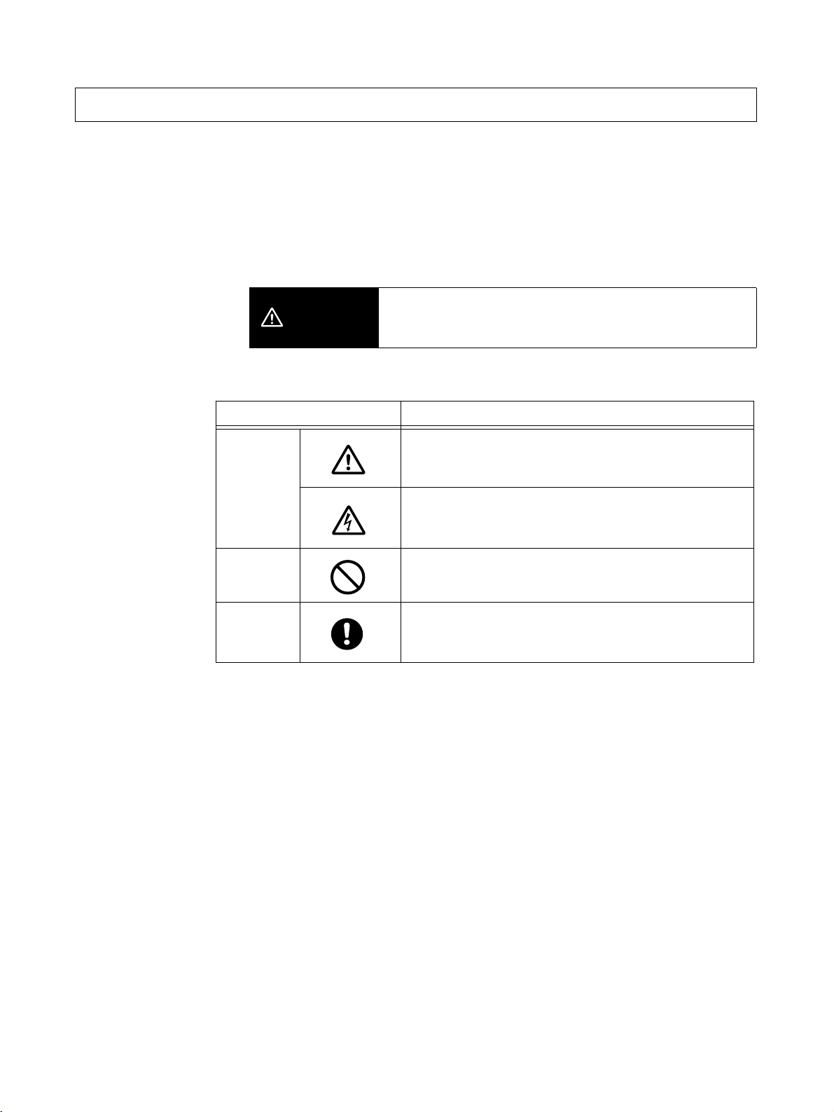
■ Definition of Precautionary Information
The following notation is used in this manual to provide precautions required
to ensure safe usage of the product.
The safety precautions that are provided are extremely important to safety.
Always read and heed the information provided in all safety precautions.
The following notation is used.
Indicates a potentially hazardous situation which, if not
CAUTION
■ Symbols
Symbol Meaning
Caution
avoided, is likely to result in minor or moderate injury or in
property damage.
General Caution
Indicates non-specific general cautions, warnings, and
dangers.
Electrical Shock Caution
Indicates possibility of electric shock under specific
conditions.
Prohibition
Mandatory
Caution
General Prohibition
Indicates non-specific general prohibitions.
General Caution
Indicates non-specific general cautions, warnings, and
dangers.
viii
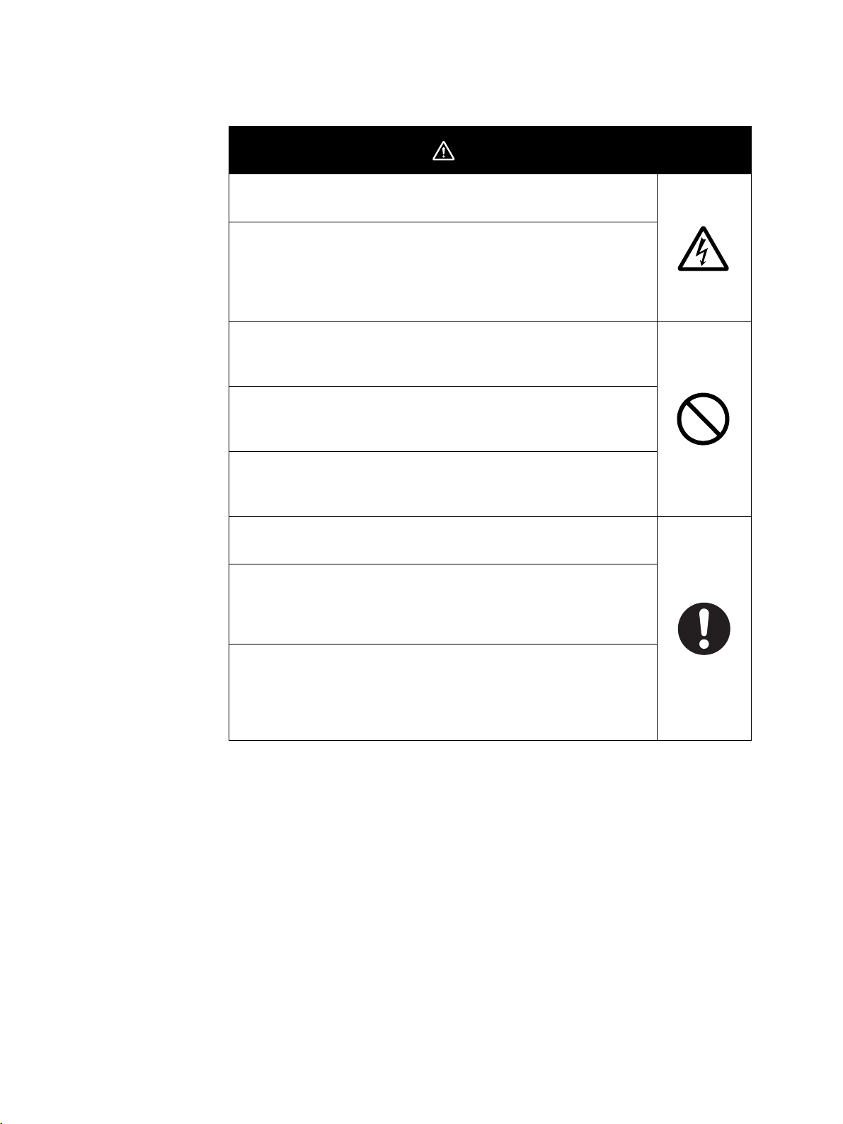
■ Safety Precautions
Do not touch the terminals while power is being supplied. Doing
so may occasionally result in minor injury due to electric shock.
Use a power supply that complies with the reinforced insulation
specified in IEC 60664 for the EJ1 external power supply or the
power supply connected to the EJ1. If non-compliant power
supplies are used, electric shock may occasionally result in minor
injury.
Do not allow pieces of metal, wire clippings, or fine metallic shavings or filings from installation to enter the product. Doing so may
occasionally result in electric shock, fire, or malfunction.
Do not use the product where subject to flammable or explosive
gas. Otherwise, minor injury from explosion may occasionally
occur.
Never disassemble, modify, or repair the product or touch any of
the internal parts. Minor electric shock, fire, or malfunction may
occasionally occur.
CAUTION
Tighten the terminal screws to between 0.40 and
0.56 N·m. Loose screws may occasionally result in fire.
Set the parameters of the product so that they are suitable for the
system being controlled. If they are not suitable, unexpected
operation may occasionally result in property damage or
accidents.
A malfunction in the product may occasionally make control
operations impossible or prevent alarm outputs, resulting in
property damage. To maintain safety in the event of malfunction of
the product, take appropriate safety measures, such as installing
a monitoring device on a separate line.
ix

Precautions for Safe Use
Be sure to observe the following precautions to prevent operation failure, malfunction, or adverse affects on
the performance and functions of the product. Not doing so may occasionally result in unexpected events.
1) The product is designed for indoor use only. Do not use the product outdoors or in any of the following
locations.
• Places directly subject to heat radiated from heating equipment
• Places subject to splashing liquid or oil atmosphere
• Places subject to direct sunlight
• Places subject to dust or corrosive gas (in particular, sulfide gas or ammonia gas)
• Places subject to intense temperature change
• Places subject to icing or condensation
• Places subject to vibration or strong shocks
2) Use and store the product within the rated ambient temperature and humidity ranges.
Mounting two or more Temperature Controllers side by side, or mounting Temperature Controllers above
each other may cause heat to build up inside the Temperature Controllers, which will shorten their service
life. If the Temperature Controllers are mounted above each other or side by side, use forced cooling by
fans or other means of air ventilation to cool down the Temperature Controllers.
3) To allow heat to escape, do not block the area around the product. Do not block the ventilation holes on
the product.
4) Be sure to wire properly with correct polarity of terminals.
5) Use specified size (M3, width 5.8 mm or less) crimped terminals for wiring. Use a gage of AWG22 to
AWG14 (equal to cross-sectional area of 0.326 to 2.081 mm
AWG28 to AWG16 (equal to cross-sectional area of 0.081 to 1.309 mm
length is 6 to 8 mm.) Up to two wires of same size and type, or two crimped terminals can be inserted into
a single terminal.
6) Do not wire terminals that do not have an identified use.
7) To reduce inductive noise, keep the wiring for the product's terminal block away from power cables
carrying high voltages or large currents. Also, do not wire power lines together with or parallel to product
wiring. Using shielded cables and using separate conduits or ducts is recommended.
Attach a surge suppressor or noise filter to peripheral devices that generate noise (in particular, motors,
transformers, solenoids, magnetic coils or other equipment that have an inductance component).
When a noise filter is used at the power supply, first check the voltage or current, and attach the noise
filter as close as possible to the product.
Allow as much space as possible between the product and devices that generate powerful high
frequencies (high-frequency welders, high-frequency sewing machines, etc.) or surge.
8) Use the product within the rated load and power supply.
9) Make sure that the rated voltage is attained within two seconds of turning ON the power using a switch or
relay contact. If the voltage is applied gradually, the power may not be reset or output malfunctions may
occur.
10) Make sure that the product has 30 minutes or more to warm up after turning ON the power before starting
actual control operations to ensure the correct temperature display.
11) The switch or circuit breaker must be within easy reach of the operator, and must be marked as a
disconnecting means for this unit.
12) Do not use paint thinner or similar chemical to clean with. Use standard grade alcohol.
13) Design the system (e.g., the control panel) allowing leeway for the delay required before product outputs
are valid after turning ON power to the product.
14) Never touch the electronic components, connectors, or patterns on product boards with your bare hands.
Always hold the product by the case. Inappropriately handling the product may occasionally damage
internal components due to static electricity.
2
) for power supply lines and a gage of
2
) for all other lines. (The stripping
x

15) Use a switch, relay, or other device with contacts to turn OFF the power supply quickly. Gradually lowering
the voltage of the power supply may result in incorrect outputs or memory errors.
16) Do not touch the electronic components with your hands or subject them to shock when removing the
terminal block.
17) Connect only the specified number of products in only a specified configuration.
18) Mount the product to a DIN Rail mounted vertically to the ground.
19) Always turn OFF the power supply before wiring the product, replacing the product, or changing the
product configuration.
20) Attach the enclosed cover seal to the connector opening on the left end Unit during installation.
21) Do not use port B on the End Unit when using port C on the HFU.
xi

Precautions for Correct Use
● Installation
1) Do not connect an End Unit directly to an HFU.
2) Always connect an End Unit to the right side of the Basic Units.
3) Always connect the HFU to the left side of the Basic Units.
4) The EJ1 cannot be used linked to a CJ-series PLC.
5) Use the EJ1G-@@ for gradient temperature control. Use the EJ1N-@@ for any other type of temperature
control.
6) When removing the terminal block to replace the Unit, be sure to confirm that the new Unit is the same as
the Unit that is being replaced.
● Service Life
1) Use the product within the following temperature and humidity ranges.
Temperature:
Humidity: 25% to 85%
When the Temperature Controller is incorporated in a control panel, make sure that the controller’s
ambient temperature and not the panel’s ambient temperature does not exceed 55
2) The service life of electronic devices like the Temperature Controller is determined by the service life of
internal electronic components. Component service life is affected by the ambient temperature: the higher
the temperature, the shorter the service life and the lower the temperature, the longer the service life.
Therefore, the service life can be extended by lowering the temperature of the Temperature Controller.
3) Mounting two or more Temperature Controllers side by side, or mounting Temperature Controllers above
each other may cause heat to build up inside the Temperature Controllers, which will shorten their service
life. If the Temperature Controllers are mounted above each other or side by side, use forced cooling by
fans or other means of air ventilation to cool down the Temperature Controllers. However, be sure not to
cool only the terminals. Doing so will result in measurement errors.
−10 to 55°C (with no icing or condensation)
°C.
● Ensuring Measurement Accuracy
1) When extending or connecting the thermocouple lead wire, be sure to use compensating wires that match
the thermocouple types.
2) When extending or connecting the lead wire of the platinum resistance thermometer, be sure to use wires
that have low resistance and keep the resistance of the three lead wires the same.
3) Mount the Temperature Controller so that it is horizontally level.
4) If the measurement accuracy is low, check to see if input shift has been set correctly.
● Precautions for Operation
1) It takes a certain amount of time for the outputs to turn ON from after the power supply is turned ON. Due
consideration must be given to this time when designing control panels, etc.
2) It takes 30 minutes from the time the product is turned ON until the correct temperature is indicated.
Always turn ON the power supply at least 30 minutes before starting temperature control.
3) Avoid using the Temperature Controller near a radio, television set, or other wireless device. Its use would
result in reception disturbance.
xii

Preparations for Use
Be sure to thoroughly read and understand the manual provided with the product, and check the following points.
Timing Check point Details
Purchasing the product Product appearance After purchase, check that the product and packaging are not dented
or otherwise damaged. Damaged internal parts may prevent optimum
control.
Product model and
specifications
Setting the Unit Product installation
location
Wiring Terminal wiring Do not subject the terminal screws to excessive stress (force) when
Power supply inputs Wire the power supply inputs correctly. Incorrect wiring will result in
Operating environment Ambient temperature The ambient operating temperature for the product is −10 to 55°C (with
Vibration and shock Check whether the standards related to shock and vibration are satis-
Foreign particles Install the product in a location that is not subject to liquid or foreign
Make sure that the purchased product meets the required specifications.
Provide sufficient space around the product for heat dissipation. Do
not block the vents on the product.
tightening them.
Make sure that there are no loose screws after tightening terminal
screws to the specified torque of 0.40 to 0.56 N·m.
Be sure to confirm the polarity for each terminal before wiring the ter-
minal block and connectors.
damage to the internal circuits.
no condensation or icing). To extend the service life of the product,
install it in a location with an ambient temperature as low as possible.
In locations exposed to high temperatures, if necessary, cool the products using a fan or other cooling method.
fied at the installation environment. (Install the product in locations
where the conductors will not be subject to vibration or shock.)
particles entering the product. If sulfide, chlorine, or other corrosive
gases are present, remove the source of the gas, install a fan, or use
other countermeasures to protect the product.
xiii

Related Manuals
The manuals related to the EJ1 are configured as shown in the following tables. Refer to these manuals as required.
■ EJ1
Name Cat. No. Contents
EJ1
EJ1N-TC2@
EJ1N-TC4@
EJ1N-HFU@
EJ1C-EDU@
Modular Temperature Controller User's Manual
CX-Thermo Ver. @ (online help)
EST2-2C-MV@
■ CS/CJ-series PLC Manuals
Name Cat. No. Contents
SYSMAC CJ Series
CJ2H-CPU@@-EIP
CPU Unit Hardware Manual
SYSMAC CJ Series
CJ2H-CPU@@-EIP
CPU Unit Software Manual
SYSMAC CJ Series
CJ1G-CPU@@, CJ1M-CPU@@, CJ1G-CPU@@P,
CJ1G/H-CPU@@H, NSJ@-@@@@(B)-G5D,
NSJ@-@@@@(B)-M3D
Programmable Controllers Operation Manual
SYSMAC CS/CJ Series
CS1G/H-CPU@@-EV1, CS1G/H-CPU@@H, CS1DCPU@@H, CS1D-CPU@@S, CJ1G-CPU@@, CJ1MCPU@@, CJ1G-CPU@@P, CJ1G/H-CPU@@H, NSJ@-
@@@@(B)-G5D, NSJ@-@@@@(B)-M3D
Programmable Controllers Programming Manual
SYSMAC CS/CJ Series
CS1G/H-CPU@@-EV1, CS1G/H-CPU@@H, CS1DCPU@@H, CS1D-CPU@@S, CJ2H-CPU@@-EIP, CJ1GCPU@@, CJ1M-CPU@@, CJ1G-CPU@@P, CJ1G/HCPU@@H, NSJ@-@@@@(B)-G5D, NSJ@-@@@@(B)-M3D
Programmable Controllers Instructions Reference Manual
SYSMAC CS Series
CS1G/H-CPU@@-EV1, CS1G/H-CPU@@H
Programmable Controllers Operation Manual
H142
(This
manual)
--(Available
only as
online
help.)
W472 Provides an outlines of and describes the
W473 Describes programming and other methods to use
W393 Provides an outlines of and describes the design,
W394 Describes programming and other methods to use
W474 Describes the ladder diagram programming
W339 Provides an outlines of and describes the design,
Describes the following information on the EJ1.
• Overview and features
• Basic specifications
• System design
• System configuration
• Mounting and wiring
• Maintenance
• Troubleshooting
Describes how to set parameters and adjust
devices (i.e., components such as Temperature
Controllers) using the CX-Thermo.
design,installation, maintenance, and other basic
operations for the CJ-series PLCs.
the functions of the CJ-series PLCs.
installation, maintenance, and other basic operations for the CJ-series PLCs.
the functions of the CS/CJ-series PLCs.
instructions supported by CS/CJ-series PLCs.
installation, maintenance, and other basic operations for the CS-series PLCs.
xiv

Name Cat. No. Contents
SYSMAC CS/CJ/NSJ Series
CS1G/H-CPU@@-EV1, CS1G/H-CPU@@H,
CS1D-CPU@@H, CS1D-CPU@@S, CJ1G-CPU@@,
CJ1M-CPU@@, CJ1G-CPU@@P, CJ1G/H-CPU@@H,
CS1W-SCB@@-V1, CS1W-SCU@@-V1,
CJ1W-SCU@@-V1, CP1H-X@@@@-@,
CP1H-XA@@@@-@, CP1H-Y@@@@-@,
Communications Commands Reference Manual
SYSMAC CS/CJ Series
CS1W-SCB@@-V1, CS1W-SCU@@-V1, CJ1W-SCU21@@-
V1
Serial Communications Boards/Units Operation Manual
■ CP-series PLC Manuals
Name Cat. No. Contents
CP1H-X40D@-@
CP1H-XA40D@-@
CP1H-Y20DT-D
SYSMAC CP Series CP1H CPU Unit Operation Manual
CP1H-X40D@-@
CP1H-XA40D@-@
CP1H-Y20DT-D
SYSMAC CP Series CP1H CPU Unit Programming Manual
CP1L-L10D@-@
CP1L-L14D@-@
CP1L-L20D@-@
CP1L-M30D@-@
CP1L-M40D@-@
CP1L-M60D@-@
SYSMAC CP Series CP1L CPU Unit Operation Manual
W342 Describes the C-series (Host Link) and FINS com-
munications commands used with CS/CJ-series
PLCs.
W336 Describes the use of Serial Communications Unit
and Boards to perform serial communications with
external devices, including the usage of standard
system protocols for OMRON products.
W450 Provides the following information on the CP
Series:
• Overview, design, installation, maintenance, and
other basic specifications
• Features
• System configuration
• Mounting and wiring
• I/O memory allocation
• Troubleshooting
Use this manual together with the CP1H Programmable Controllers Programming Manual (W451).
W451 Provides the following information on the CP
Series:
• Programming instructions
• Programming methods
• Tas k s
• File memory
• Functions
Use this manual together with the CP1H Programmable Controllers Operation Manual (W450).
W462 Provides the following information on the CP
Series:
• Overview, design, installation, maintenance, and
other basic specifications
• Features
• System configuration
• Mounting and wiring
• I/O memory allocation
• Troubleshooting
Use this manual together with the CP1L Programmable Controllers Programming Manual (W451).
xv

Name Cat. No. Contents
CP1H-X40D@-@
CP1H-XA40D@-@
CP1H-Y20DT-D
CP1L-L10D@-@
CP1L-L14D@-@
CP1L-L20D@-@
CP1L-M30D@-@
CP1L-M40D@-@
CP1L-M60D@-@
SYSMAC CP Series CP1H /CP1L CPU Unit Programming
Manual
CP1L-L10D@-@
CP1L-L14D@-@
CP1L-L20D@-@
CP1L-M30D@-@
CP1L-M40D@-@
CP1L-M60D@-@
SYSMAC CP Series CP1L CPU Unit Introduction Manual
W451 Provides the following information on programming
the CP Series:
• Programming methods
• Tas k s
• Programming instructions
W461 Describes basic setup methods of CP1L PLCs:
• Basic configuration and component names
• Mounting and wiring
• Programming, data transfer, and debugging
using the CX-Programmer
• Application program examples
■ G3ZA Multi-channel Power Controller Manual
Name Cat. No. Contents
G3ZA
G3ZA-4H203-FLK-UTU
G3ZA-4H403-FLK-UTU
G3ZA-8H203-FLK-UTU
G3ZA-8H403-FLK-UTU
Multi-channel Power Controller User's Manual
Z200 Provides an outline of and describes the features,
installation, wiring, RS-485 serial communications
settings, and basic function for the G3ZA Multichannel Power Controller.
■ G3PW Power Controller Manual
Name Cat. No. Contents
G3PW
G3PW-A220EC-C-FLK
G3PW-A230EC-C-FLK
G3PW-A245EC-C-FLK
G3PW-A260EC-C-FLK
G3PW-A220EC-S-FLK
G3PW-A230EC-S-FLK
G3PW-A245EC-S-FLK
G3PW-A260EC-S-FLK
Power Controller User’s Manual
Z280 Provides an outline of and describes the features,
■ Programmable Terminal (PT) Manuals
Name Cat. No. Contents
NS-Series
NS5-SQ0@(B)-V1/V2, NS5-TQ0@(B)-V2,
NS5-MQ0@(B)-V2, NS8-TV@@(B)-V1/V2,
NS10-TV0@(B)-V1/V2, NS12-TS0@(B)-V1/V2,
NS5-SQ1@@-V2, NS5-TQ1@@-V2, NS5-MQ1@@-V2
Programmable Terminals Setup Manual
NS-Series
NS5-SQ0@(B)-V1/V2, NS5-TQ0@(B)-V2,
NS5-MQ0@(B)-V2, NS8-TV@@(B)-V1/V2,
NS10-TV0@(B)-V1/V2, NS12-TS0@(B)-V1/V2,
NS5-SQ1@@-V2, NS5-TQ1@@-V2, NS5-MQ1@@-V2
Programmable Terminals Programming Manual
V083 Provides an outline of, and describes the design,
V073 Describes the functions of NS-series PTs, includ-
installation, wiring, RS-485 serial communications
settings, and basic function for the G3PW Power
Controller.
installation, maintenance, and other basic operations for the NS-series PTs. Information is also
included on connecting to hosts and peripheral
devices, and settings required for communications
and PT operation.
ing screen configurations, object functions, and
host communications for the PT.
xvi

Name Cat. No. Contents
NSJ-Series
NSJ5-TQ@@(B)-G5D
NSJ5-SQ@@(B)-G5D
NSJ8-TV@@(B)-G5D
NSJ10-TV@@(B)-G5D
NSJ12-TS@@(B)-G5D
NSJ5-TQ@@(B)-M3D
NSJ5-SQ@@(B)-M3D
NSJ8-TV@@(B)-M3D
NSJ Series Operation Manual
NSH Series
NSH5-SQR00B-V2
NSH5-SQG00B-V2
Hand-held Programmable Terminal Operation Manual
NS Series
NS-CA002
Programmable Terminals RGB and Video Input Unit Operation Manual
Smart Active Parts Reference Manual V087
W452 Provides the following information about the NSJ-
V090
(PDF
only)
V086
(PDF
only)
(PDF
only)
series NSJ Controllers:
Overview and features
Designing the system configuration
Installation and wiring
I/O memory allocations
Troubleshooting and maintenance
Use this manual in combination with the following
manuals: SYSMAC CS Series Operation Manual
(W339), SYSMAC CJ Series Operation Manual
(W393), SYSMAC CS/CJ Series Programming
Manual (W394), and NS-V1/-V2 Series Setup
Manual (V083)
Provides an outline of, and describes the design,
installation, maintenance, and other basic operations for the NSH-series NSH5 Hand-held Programmable Terminal. Information is also included
on features, system configuration, wiring, I/O
memory allocations, and troubleshooting.
Describes how to display external video images or
analog RGB imagines on NS-series PTs using a
NS-series RGB and Video Input Unit, including the
following information.
• Features, system configuration, and specifications
• Functions, setting methods, and adjustment
methods
Describes the Smart Active Parts (SAP) functionality and the settings required to use the SAP
library. This document does not describe application restrictions for specific Units or Components
or restrictions in combinations. Always refer to the
operation manual for the products involved before
using the SAP library.
xvii

■ Support Software Manuals
Name Cat. No. Contents
CXONE-AL@@C-EV3/AL@@D-EV3
CX-One Ver. 3.0 FA Integrated Tool Package Setup Manual
CXONE-AL@@C-EV3/ CXONE-AL@@D-EV3
CX-Integrator Ver. 3.0 Operation Manual
SYSMAC WS02-CXPC@-E-V8
CX-Programmer Operation Manual
SYSMAC WS02-CXPC@-E-V8
CX-Programmer Ver. 8.0 Operation Manual
Function Blocks
(CS1G-CPU
CJ1G-CPU
CJ1M-CPU
CP1H-XA
CPU Units)
SYSMAC CX-Designer Ver. 1.0
NS-CXDC1-V1
Operation Manual
NS-Series
NS5-SQ0@(B)-V1/V2
NS5-TQ0@(B)-V2
NS5-MQ0@(B)-V2
NS8-TV@@(B)-V1/V2
NS10-TV0@(B)-V1/V2
NS12-TS0@(B)-V1/V2
NSJ5-TQ@@(B)-G5D
NSJ5-SQ@@(B)-G5D
NSJ8-TV@@(B)-G5D
NSJ10-TV@@(B)-G5D
NSJ12-TS@@(B)-G5D
Ladder Monitor Operation Manual (Ladder Monitor/I/O
Comment Extracting Tool)
@@H, CS1H-CPU@@H,
@@H, CJ1H-CPU@@H,
@@, CP1H-X@@@@-@,
@@@@-@, CP1H-Y@@@@-@
W463 Installation and overview of CX-One FA Integrated
Tool Package.
W464 Describes operating procedures for the CX-Inte-
grator Network Configuration Tool for CS-, CJ-,
CP-, and NSJ-series Controllers.
W446 Provides information on how to use the CX-Pro-
grammer for all functionality except for function
blocks.
Refer to the following manuals when programming:
CJ Series CPU Unit Hardware Manual (Cat. No.
W472) and CJ Series CPU Unit Software Manual
(Cat. No. W473).
CS Series: Operation Manual for Setup (Cat. No.
W339) and Programming Manual for Programma-
ble Controllers (Cat. No. W394)
CJ Series: CJ Series Programmable Controllers
Operation Manual (Cat. No. W393) and Program-
ming Manual for Programmable Controllers (Cat.
No. W394)
W447 Describes the functionality unique to the CX-Pro-
grammer Ver. 7.0 and CP-series CPU Units or CS/
CJ-series CPU Units with unit version 3.0 or later
based on function blocks. Functionality that is the
same as that of the CX-Programmer is described
in W446 (enclosed).
V088 Describes how to install and use the CX-Designer,
including screen data creation methods, screen
data transfer methods, and system settings.
V082 Describes the NS-series PT monitoring function
for CS/CJ-series PLC ladder programs, including
the following information.
• Overview and features
• Setup methods
• Basic operations
• Troubleshooting
xviii

Conventions Used in This Manual
Meanings of Abbreviations
The following abbreviations are used in parameter names, figures and in text explanations. These
abbreviations mean the following:
Symbol Term
TC4/TC2 Four-channel and Two-channel Basic Units
ch Channel
HFU Advanced Unit
EDU End Unit
PV Process value
SP Set point
RSP Remote SP
LSP Local SP
LBA Loop burnout alarm
HB Heater burnout
HS Heater short
OC Heater overcurrent
AT Autotuning
ST Self-tuning
EU Engineering unit (See note.)
Note “EU” stands for Engineering Unit. EU is used as the minimum unit for engineering units such as
°C, m, and g. The size of EU varies according to the input type.
For example, when the input temperature setting range is –200 to +1300
when the input temperature setting range is –20.0 to +500.0
°C, 1 EU is 0.1°C.
°C, 1 EU is 1°C, and
For analog inputs, the size of EU varies according to the decimal point position of the scaling setting, and 1 EU becomes the minimum scaling unit.
xix

xx

TABLE OF CONTENTS
SECTION 1
Outline . . . . . . . . . . . . . . . . . . . . . . . . . . . . . . . . . . . . . . . . . . . 1
1-1 Names of Parts. . . . . . . . . . . . . . . . . . . . . . . . . . . . . . . . . . . . . . . . . . . . . . . . . . . . . . . . . . . . 2
1-2 I/O Configuration and Main Functions . . . . . . . . . . . . . . . . . . . . . . . . . . . . . . . . . . . . . . . . . 5
1-3 Internal Block Diagrams . . . . . . . . . . . . . . . . . . . . . . . . . . . . . . . . . . . . . . . . . . . . . . . . . . . . 9
SECTION 2
Preparations . . . . . . . . . . . . . . . . . . . . . . . . . . . . . . . . . . . . . . 11
2-1 Installation . . . . . . . . . . . . . . . . . . . . . . . . . . . . . . . . . . . . . . . . . . . . . . . . . . . . . . . . . . . . . . . 12
2-2 Wiring Terminals . . . . . . . . . . . . . . . . . . . . . . . . . . . . . . . . . . . . . . . . . . . . . . . . . . . . . . . . . . 16
2-3 Using Tool Ports . . . . . . . . . . . . . . . . . . . . . . . . . . . . . . . . . . . . . . . . . . . . . . . . . . . . . . . . . . 26
2-4 Unit Configuration Examples . . . . . . . . . . . . . . . . . . . . . . . . . . . . . . . . . . . . . . . . . . . . . . . . 27
SECTION 3
Typical Control Examples . . . . . . . . . . . . . . . . . . . . . . . . . . . 33
3-1 Minimum Configuration for Control . . . . . . . . . . . . . . . . . . . . . . . . . . . . . . . . . . . . . . . . . . . 34
3-2 Multi-channel Control . . . . . . . . . . . . . . . . . . . . . . . . . . . . . . . . . . . . . . . . . . . . . . . . . . . . . . 38
3-3 Control Linked to a Host Device . . . . . . . . . . . . . . . . . . . . . . . . . . . . . . . . . . . . . . . . . . . . . . 41
3-4 Controlling G3ZA Controllers Connected to Output Devices . . . . . . . . . . . . . . . . . . . . . . . 45
SECTION 4
Basic Units (TC4 and TC2) Functions . . . . . . . . . . . . . . . . . 49
4-1 Setting Input Specifications. . . . . . . . . . . . . . . . . . . . . . . . . . . . . . . . . . . . . . . . . . . . . . . . . . 51
4-2 Setting Output Specifications . . . . . . . . . . . . . . . . . . . . . . . . . . . . . . . . . . . . . . . . . . . . . . . .57
4-3 Setting Control Specifications . . . . . . . . . . . . . . . . . . . . . . . . . . . . . . . . . . . . . . . . . . . . . . . .64
4-4 Setting Alarm Specifications . . . . . . . . . . . . . . . . . . . . . . . . . . . . . . . . . . . . . . . . . . . . . . . . .86
4-5 Detecting Current Errors . . . . . . . . . . . . . . . . . . . . . . . . . . . . . . . . . . . . . . . . . . . . . . . . . . . . 91
4-6 Using the Loop Break Alarm (LBA) . . . . . . . . . . . . . . . . . . . . . . . . . . . . . . . . . . . . . . . . . . . 102
4-7 Other Functions (TC4 and TC2) . . . . . . . . . . . . . . . . . . . . . . . . . . . . . . . . . . . . . . . . . . . . . . 104
SECTION 5
Advanced Unit (HFU) Functions. . . . . . . . . . . . . . . . . . . . . . 115
5-1 Programless Communications . . . . . . . . . . . . . . . . . . . . . . . . . . . . . . . . . . . . . . . . . . . . . . . . 116
5-2 Connecting More Than One HFU . . . . . . . . . . . . . . . . . . . . . . . . . . . . . . . . . . . . . . . . . . . . 155
5-3 Other HFU Functions . . . . . . . . . . . . . . . . . . . . . . . . . . . . . . . . . . . . . . . . . . . . . . . . . . . . . . 164
SECTION 6
CompoWay/F Communications . . . . . . . . . . . . . . . . . . . . . . 167
6-1 Communications Settings . . . . . . . . . . . . . . . . . . . . . . . . . . . . . . . . . . . . . . . . . . . . . . . . . . .168
6-2 Frame Configuration . . . . . . . . . . . . . . . . . . . . . . . . . . . . . . . . . . . . . . . . . . . . . . . . . . . . . . . 170
6-3 FINS-mini Text . . . . . . . . . . . . . . . . . . . . . . . . . . . . . . . . . . . . . . . . . . . . . . . . . . . . . . . . . . . 172
6-4 Detailed Description of Services . . . . . . . . . . . . . . . . . . . . . . . . . . . . . . . . . . . . . . . . . . . . . . 174
xxi

TABLE OF CONTENTS
SECTION 7
Modbus Communications . . . . . . . . . . . . . . . . . . . . . . . . . . . 189
7-1 Communications Settings . . . . . . . . . . . . . . . . . . . . . . . . . . . . . . . . . . . . . . . . . . . . . . . . . . .190
7-2 Frames . . . . . . . . . . . . . . . . . . . . . . . . . . . . . . . . . . . . . . . . . . . . . . . . . . . . . . . . . . . . . . . . . . 192
7-3 Function Codes . . . . . . . . . . . . . . . . . . . . . . . . . . . . . . . . . . . . . . . . . . . . . . . . . . . . . . . . . . . 194
7-4 Variable Areas . . . . . . . . . . . . . . . . . . . . . . . . . . . . . . . . . . . . . . . . . . . . . . . . . . . . . . . . . . . . 195
7-5 Detailed Description of Services . . . . . . . . . . . . . . . . . . . . . . . . . . . . . . . . . . . . . . . . . . . . . . 196
SECTION 8
Errors and Error Processing . . . . . . . . . . . . . . . . . . . . . . . . . 203
8-1 Things to Check First . . . . . . . . . . . . . . . . . . . . . . . . . . . . . . . . . . . . . . . . . . . . . . . . . . . . . . 204
8-2 Determining Errors from Indicators . . . . . . . . . . . . . . . . . . . . . . . . . . . . . . . . . . . . . . . . . . . 205
8-3 Determining the Error from the Status . . . . . . . . . . . . . . . . . . . . . . . . . . . . . . . . . . . . . . . . . 207
8-4 Determining the Error from the Current Situation for Communications Errors . . . . . . . . . . 212
8-5 Determining the Error from the Current Situation for Temperature Measurement Errors . . 221
8-6 Determining the Error from the Current Situation for Temperature Control Errors . . . . . . . 222
8-7 Determining the Error from the Current Situation for Output Errors . . . . . . . . . . . . . . . . . . 224
8-8 Determining the Error from the Current Situation for Heater Burnout Alarm Errors. . . . . . 225
Appendix . . . . . . . . . . . . . . . . . . . . . . . . . . . . . . . . . . . . . . . . . 227
Index. . . . . . . . . . . . . . . . . . . . . . . . . . . . . . . . . . . . . . . . . . . . . 271
Revision History . . . . . . . . . . . . . . . . . . . . . . . . . . . . . . . . . . . 279
xxii

About this Manual:
This manual describes the EJ1 Modular Temperature Controllers and includes the sections described
below. Please read this manual carefully and be sure you understand the information provided before
attempting to set up or operate an EJ1 Modular Temperature Controller.
•Overview
Section 1 Outline describes the features, nomenclature, and functions of the EJ1.
•Setup
Section 2 Preparations describes the preparations required to use the EJ1, including installation, wiring, and switch settings.
• Application Examples
Section 3 Typical Control Examples describes the basic applications of the EJ1 using specific control examples.
• Functions of EJ1 Basic Units (TC4/TC2)
Section 4 Basic Units (TC4/TC2) describes the functions of EJ1 Basic Units.
• Functions of the EJ1 Advanced Unit (HFU)
Section 5 Advanced Unit (HFU) Functions describes the functions of EJ1 Advanced Unit.
• Operation Using Communications
Section 6 Communications (CompoWay/F) and Section 7 Communications (Modbus) describes
how to use communications based on communications commands.
• Troubleshooting
Section 8 Troubleshooting describes methods for checking possible problems in operation depending on classifications of Temperature Controller status.
• Specifications and Parameter Lists
Appendix provides specifications, parameter lists, status lists, and other reference information.
!WARNING Failure to read and understand the information provided in this manual may result in per-
sonal injury or death, damage to the product, or product failure. Please read each section
in its entirety and be sure you understand the information provided in the section and
related sections before attempting any of the procedures or operations given.
xxiii

Functional Upgrades
The EJ1C-EDUC-NFLK (with connector terminal block) has been added to the End Units (EDU) and
the functions of previous models have been improved. Information in this manual related to improved
functionality is indicated with the mark. The improved functionality is outlined below.
• Basic Units (TC4/TC2)
• Autotuning is provided for heating/cooling control.
• Self-tuning has been added.
• A switch can be used to display the output status on the operation indicators during operation.
• Modbus communications can be used to read and write all parameters, and to executed any of the
operation commands.
• A switch setting can be changed to use Modbus communications on port B.
• A switch setting can be used to set the baud rate of port B.
• A C0/80 status has been added for to the variable types.
• Up to eight G3PW Power Controllers can be connected to one Basic Unit.
Note 1. The G3PW can be connected to EJ1 V1.1.
2. The G3PW and G3ZA cannot be used together.
• Advanced Unit (HFU)
V1.2
V1.2
• Bit specification operation commands have been added to the parameters that can be specified for
programless download settings. This simplifies the program when operation commands are executed.
• The G3ZA or G3PW Monitor parameter has been added to the parameters that can be specified for
programless upload settings. Up to four G3ZA Multi-channel Power Controllers or up to four G3PW
Power Controllers can be connected to one TC4/ TC2 Unit.
• The maximum number of parameters that can be specified for programless upload/download setting
has been increased from 600 to 1200 each.
• The maximum number of TC4/TC2 Units that an HFU can control has been increased from 16 to 32
Units.
• Communications unit numbers 32 to 39 can be used in the HFU via programless communications.
This allows the communications unit numbers of TC4/TC2 connected to an HFU to be numbered
sequentially, making it easy to copy HFU and TC settings to other HFUs and TCs.
• Support Software
Use version 4.10 or higher of the CX-Thermo when using the upgraded functions.
xxiv
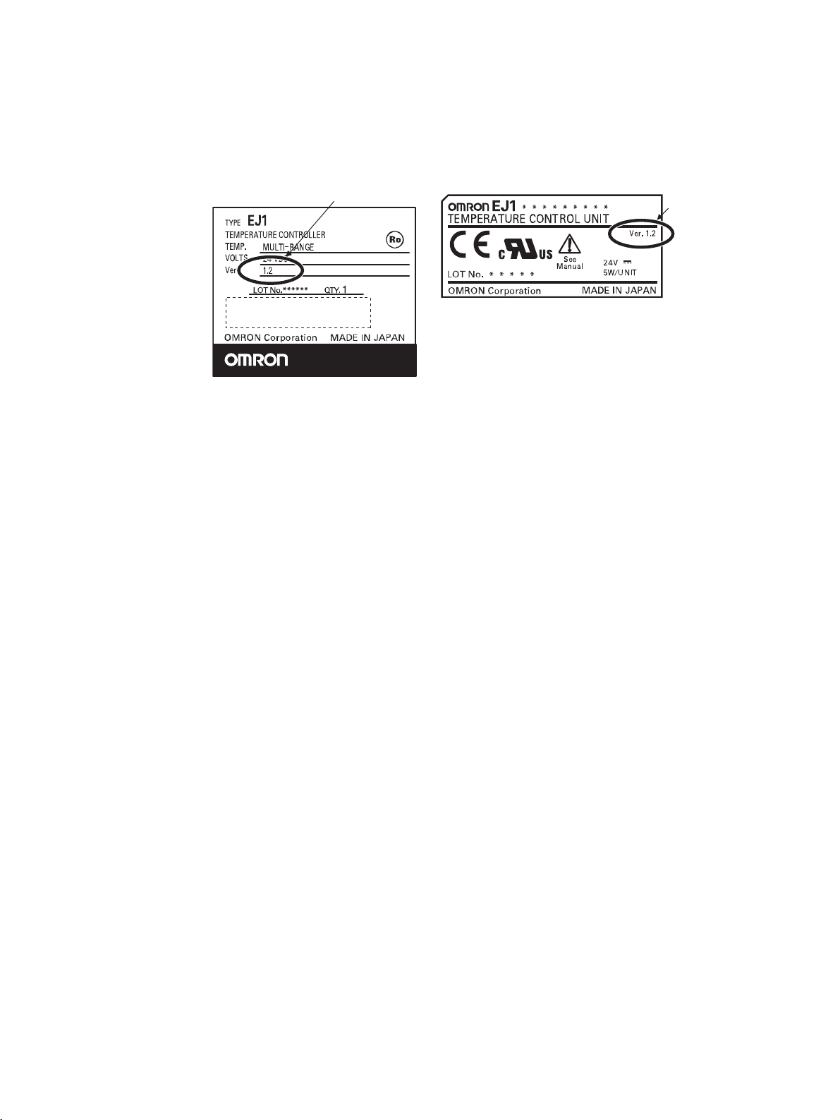
• Identifying Upgraded Models
The new functionality can be used with version 1.2 (V1.2). Check the label on the Temperature Controller or the box to determine the version. Models not marked “Ver. 1.1” are version 1.0.
Box Label
Version
Temperature Controller Label
Version
xxv

Functional Upgrades
EJ1 Temperature Controllers with linear outputs (EJ1N-TC2A-CNB and EJ1N-TC2B-CNB) have been
added and the functions of the previous EJ1 Controllers with pulse outputs have been improved. Information in this manual related to improved functionality is indicated with this mark: . The improved
functionality is outlined below.
• Basic Units (TC4/TC2)
• Modbus communications can be used on port B.
• Software version 2 of the G3ZA Multi-channel Power Controller can be used.
Note 1. When more than one G3ZA Multi-channel Power Controller is connected, version 1 and ver-
sion 2 can be mixed. (Up to 8 G3ZA Multi-channel Power Controllers can be connected.)
2. Software version 2 of G3ZA Multi-channel Power Controller can also be used with EJ1 version
1.0.
• Advanced Unit (HFU)
• Programless communications can be used with 1: N connections.
• The maximum number of parameters that can be specified for programless upload/download settings
has been increased from 300 to 600 each.
• Connection is now possible to MELSEC-QnA/An/AnS/FX3uc-series PLCs.
• A new setting read operation has been added to programless communications: Setting Read 2.
• The speed of programless communications has been increased.
• Either “continue” or “stop” can be selected for when errors occur in programless communications.
V1.1
V1.1
• Support Software
Use version 3.20 or higher of the CX-Thermo when using the upgraded functions.
• Identifying Upgraded Models
The new functionality can be used with version 1.1 (V1.1). Check the label on the Temperature Controller or the box to determine the version. Models not marked “Ver. 1.1” are version 1.0.
Box Label
TYPE
EJ1 ******
TEMPERATURE CONTROLLER
TEMP.
VOLTS
Ver.
MULTI-RANGE
24VDC
V1.1
LOT No.
****
Version
QTY. 1
Temperature Controller Label
Version
xxvi

This section describes the features, nomenclature, and functions of the EJ1.
1-1 Names of Parts . . . . . . . . . . . . . . . . . . . . . . . . . . . . . . . . . . . . . . . . . . . . . . . . 2
1-1-1 Appearance . . . . . . . . . . . . . . . . . . . . . . . . . . . . . . . . . . . . . . . . . . . . 2
1-1-2 Names of Parts on Front Panel . . . . . . . . . . . . . . . . . . . . . . . . . . . . . 2
1-1-3 Meanings of Indicators . . . . . . . . . . . . . . . . . . . . . . . . . . . . . . . . . . . 3
1-1-4 Using Setting Switches. . . . . . . . . . . . . . . . . . . . . . . . . . . . . . . . . . . 3
1-2 I/O Configuration and Main Functions. . . . . . . . . . . . . . . . . . . . . . . . . . . . . . 5
1-2-1 I/O Configuration . . . . . . . . . . . . . . . . . . . . . . . . . . . . . . . . . . . . . . . 5
1-2-2 Main Unit Functions. . . . . . . . . . . . . . . . . . . . . . . . . . . . . . . . . . . . . 6
1-2-3 Model Number Legend. . . . . . . . . . . . . . . . . . . . . . . . . . . . . . . . . . . 7
1-3 Internal Block Diagrams . . . . . . . . . . . . . . . . . . . . . . . . . . . . . . . . . . . . . . . . . 9
SECTION 1
Outline
1
Names of Parts Section 1-1
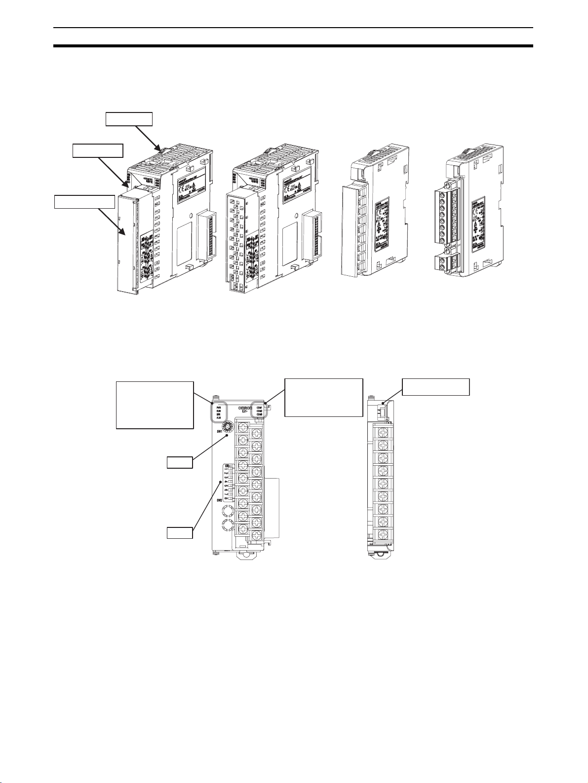
1-1 Names of Parts
1-1-1 Appearance
Slider
Front panel
Terminal block
TC4, TC2, or HFU
Screw Terminals
TC4, TC2, or HFU
Screw-Less Clamp Terminals
1-1-2 Names of Parts on Front Panel
Operation Indicators
PWR 1
RUN 2
ERR 3
ALM 4
SW1
SW2
TC4, TC2, or HFU EDU
Operation Indicators
COM1
COM2
COM3
EDUA
Models with Screw
Terminals
EDUC
Connector terminal
block model
Port A connector
2
Names of Parts Section 1-1
1-1-3 Meanings of Indicators
Operation Indicators
TC4 and TC2
Name Color Meaning: When SW2 No. 6 is OFF Meaning: When SW2 No. 6 is ON
PWR/1 Green Lights when the power is ON. Lit when output 1 is ON.
RUN/2 Green Lights during operation. Lit when output 2 is ON.
ERR/3 Red Flashes or lights when an error occurs. Lit when output 3 is ON.
ALM/4 Red Lights when an alarm is activated. Lit when output 4 is ON.
COM1 Orange Flashes during communications via port A on the End Unit.
COM2 Orange Flashes during communications via port B on the End Unit.
COM3 Orange Flashes during communications with the G3ZA.
HFU
V1.2
V1.2
V1.2
V1.2
Name Color Meaning
PWR Green Lights when the power is ON. (See note.)
RUN Green --ERR Red Flashes or lights when an error occurs.
ALM Red Lights when an alarm is activated.
COM1 Orange Flashes during communications via port A on the End Unit.
COM2 Orange Flashes when the EJ1 system is in operation.
COM3 Orange Flashes during communications via port C.
Note Some time is required for the indicators to light after the power is turned ON.
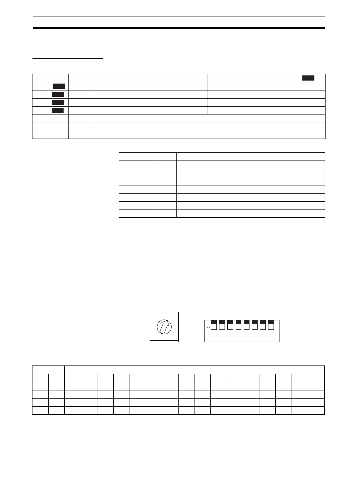
1-1-4 Using Setting Switches
• Check that the EJ1 is turned OFF before operating the switches. The settings are enabled when the power is turned ON.
• Set the switches with a small flat-blade screwdriver. Do not set the
switches midway between settings.
V1.2
Setting the Unit
Number
Unit Number Settings
SW2 SW1
120123456789ABCDE F
OFF OFF 00 01 02 03 04 05 06 07 08 09 10 11 12 13 14 15
ONOFF16171819202122232425262728293031
OFFON32333435363738394041424344454647
ON ON 48 49 50 51 52 53 54 55 56 57 58 59 60 61 62 63
SW1 and SW2 are used together to set the unit number to between 00 and
63.
Note The factory setting is unit number 01.
0
1
2
F
3
E
4
D
5
C
6
B
7
A
8
9
SW1 SW2
1 2 3 4 5 6 7 8
ON
3
Names of Parts Section 1-1
Setting Switch 2
(SW2) Settings
EJ1@-TC Basic Units
SW2 Meaning
3 Set to ON when using the Modbus communications protocol for port B.
V1.2
OFF: The setting for port B communications protocol is used.
ON: Modbus is used.
4 to 5 Set the baud rate of port B.
V1.2
4 = OFF, 5 = OFF: Use the baud rate parameter setting for port B
4 = ON, 5 = OFF: 19.2 kbps
4 = OFF, 5 = ON: 38.4 kbps
4 = ON, 5 = ON: 115.2 kbps
6 Set to ON to display the output status on the operation indicators.
V1.2
OFF: The operation status is displayed (PWR, RUN, ERR, and ALM).
ON: The output status is displayed (outputs 1, 2, 3, and 4).
Note Normally keep this pin set to OFF so that the operation status
can be checked.
7 ON: G3ZA Multi-channel Power Controller in operation
ON when using a G3PW Power Controller.
8 Use when an HFU is used and Units are distributed. (See note.)
(default: 9.6 kbps).
V1.1
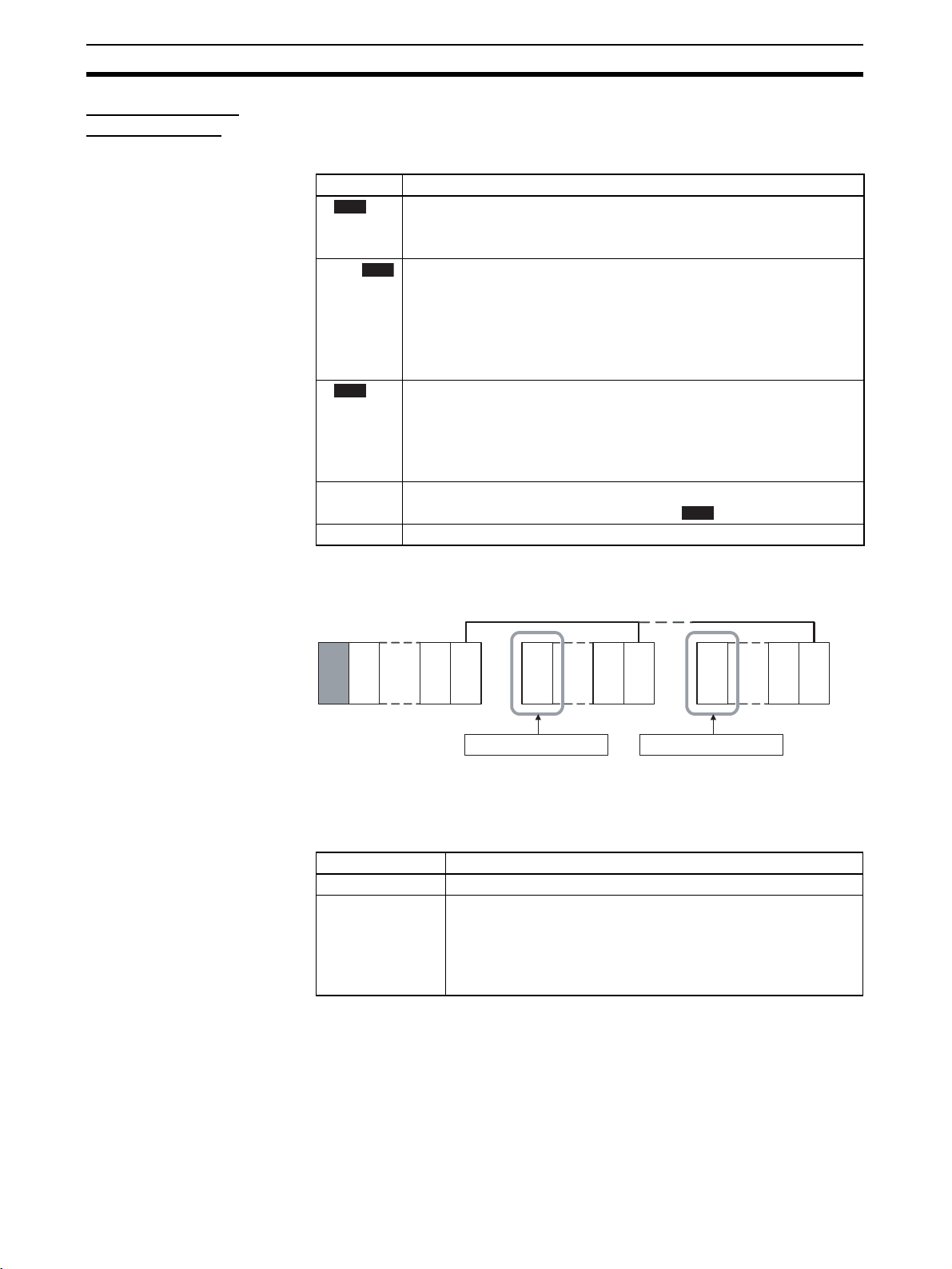
EJ1@-HFU (Advanced
Unit)
Note To use an HFU with distributed positioning, turn ON pin number 8 on SW2 on
the TC Unit connected at the left end of the Block.
Refer to SECTION 2 Preparations for information on wiring.
HFU
TC4/2
EDU
TC4/2
Turn ON pin 8 on SW2.
TC4/2
EDU
TC4/2
Turn ON pin 8 on SW2.
TC4/2
TC4/2
EDU
Note Make sure power to the Unit is turned OFF before making settings for No. 6.
Settings can be made for No. 6 can be turned ON or OFF with the power ON.
SW2 Meaning
3 to 7 Not used (OFF)
8•EJ1@-HFU@-NFLK
OFF: RS-485 is selected.
ON: RS-232C is selected.
•EJ1@-HFU@-NFL2
Not used (OFF).
4
I/O Configuration and Main Functions Section 1-2
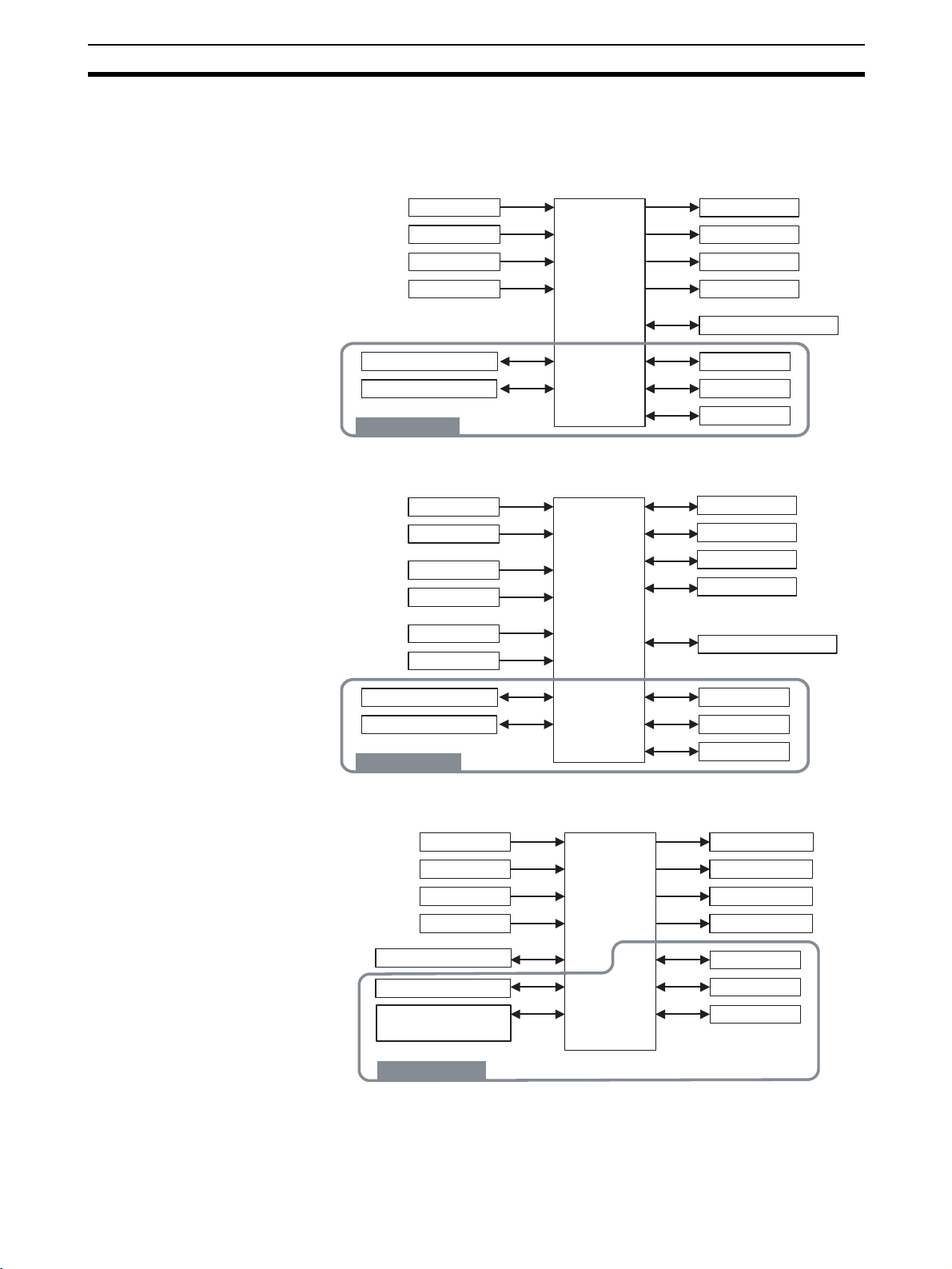
1-2 I/O Configuration and Main Functions
1-2-1 I/O Configuration
TC4: Four-channel Basic
Unit
Main input 1
Main input 2
Main input 3
Main input 4
Control
section
Control output 1
Control output 2
Control output 3
Control output 4
G3ZA communications
TC2: Two-channel Basic
Unit
HFU (Advanced Unit)
Port A communications
Port B communications
Inside the device
Internal bus 1
Internal bus 2
Internal bus 3
• Internal device I/O are connected via a connector to the adjacent Unit.
Main input 1
Main input 2
Event input 1
Event input 2
CT input 1
CT input 2
Port A communications
Port B communications
Inside the device
Control
section
Control output 1
Control output 2
Control output 3
Control output 4
G3ZA communications
Internal bus 1
Internal bus 2
Internal bus 3
• Internal device I/O are connected via a connector to the adjacent Unit.
Event input 1
Event input 2
Event input 3
Event input 4
Control
section
Auxiliary output 1
Auxiliary output 2
Auxiliary output 3
Auxiliary output 4
Port C communications
Port A communications
Communications
between Units
Inside the device
Internal bus 1
Internal bus 2
Internal bus 3
• Internal device I/O are connected via a connector to the adjacent Unit.
• Communications between devices are connected to TC4 or TC2 host
device communications.
5

I/O Configuration and Main Functions Section 1-2
EDU: End Unit
Adjacent Unit
Note Auxiliary outputs are output via an internal bus.
Port A communications
Port B communications
Auxiliary output 1 (See note.)
Auxiliary output 2 (See note.)
1-2-2 Main Unit Functions
Basic Units (TC4 and
TC2)
TC4 • One TC4 Unit controls temperature on 4 channels.
TC2 • One TC2 Unit controls temperature on 2 channels.
• The Basic Units are modular temperature controllers with I/O.
• There are two models of Basic Unit: The TC4 with four I/O channels and
the TC2 with two I/O channels.
• Up to eight G3ZA Multi-channel Power Controllers, or V1.1 G3PW Power
Controllers , can be connected to each Basic Unit.
• Multi-input is supported for thermocouple, platinum resistance thermometer, or analog input.
• The type of input can be set separately for each channel.
• Control outputs are pulse voltage outputs.
• Both screw terminals and screw-less clamp terminals are available.
• Terminal blocks can be detached and attached.
• Multi-input is supported for thermocouple, platinum resistance thermometer, or analog input.
• The type of input can be set separately for each channel.
• Control outputs are pulse voltage outputs or current outputs
• Connect a current transformer (CT) to use the heater burnout and heater
overcurrent alarms.
• There are two event inputs. Any of the following can be used by setting
event input assignments: Run/stop, auto/manual, remote SP/local SP, and
bank switching.
• Both screw terminals and screw-less clamp terminals are available.
• Terminal blocks can be detached and attached.
V1.1
Advanced Unit (HFU) • An HFU monitors the Basic Units and collects data.
• Up to sixteen Basic Units, or 32 version Units, can be connected to
one HFU.
• Data can be exchanged between the EJ1 and PLCs using programless
communications.
• With version V1.0, up to 300 data items can be read from a PLC to the
EJ1 and up to 300 data items can be written from the EJ1 to a PLC. With
version , up to 600 data items can be read from a PLC to the EJ1
and up to 600 data items can be written from the EJ1 to a PLC. With version , up to 1,200 data items can be read from a PLC to the EJ1 and
up to 1,200 data items can be written from the EJ1 to a PLC.
V1.1
V1.2
V1.2
6

I/O Configuration and Main Functions Section 1-2
• OMRON CS/CJ-series PLCs and Mitsubishi Q/QnA/QnAS/An/AnS/
FX3UC-series PLCs can be connected. (Version or higher must be
V1.1
used for An/AnS/FX3UC-series PLCs.
End Unit (EDU) • The End Unit supplies power to connected Basic Units and HFUs.
• An End Unit is always required when using the EJ1.
• A total of up to 16 HFUs and Basic Units can be connected to one End
Unit.
• The End Unit has two communications ports: port A and port B. Write
Mode is valid for port B. If settings are changed from port A, they are
always written to EEPROM. When using port A, be sure to consider the
write life of the EEPROM.
• Two communications ports are provided for port A: a connector and terminal block connections.
• The connector communications port can be used as a tool port. The End
Unit can be connected to a computer via a special E58-CIFQ1 USB-Serial
Conversion Cable to make EJ1 settings using the CX-Thermo Support
Software.
• The terminal block communications port can be used to wire between
more than one EJ1 for distributed positioning of the EJ1. Up to 64 HFUs
and Basic Units can be connected this way.
1-2-3 Model Number Legend
TC4 and TC2
Options
Outputs
Terminal
type
Unit name
Type Standard control
None
H
B
Q
N
A
B
T C 4
T C 2
N
2 CT inputs
2 event inputs
2 pulse voltage outputs
2 transistor outputs
Screw terminals
Screw-less clamp terminals
Four-channel Temperature Control Unit
Two-channel Temperature Control Unit
1 2 3 4 5 6 7 8 9 10 11 12 13 14
N - T C 4 A Q Q1JE -
N - T C 4 B Q Q1JE -
N - T C 2 A Q N H B1JE -
N
-
T
C
2
B
Q
N
J
E
N
-
T
1
J
E
N
1
J
E
C
-
T
C
-
2
A
-
2
B
-
H
C
N
B
C
N
B
B1
7

I/O Configuration and Main Functions Section 1-2
-
-
HFU
Communications
Outputs
Terminal
type
Unit name
Type
EDU
Communications
Outputs 2 transistor outputs
Terminal type
Unit name
Type
FLK
FL2
N
A
B
HFU
N
FLK
N
A
C
EDU
C
CompoWay/F (RS-485/RS-232C)
CompoWay/F (RS-422)
4 transistor outputs
Screw terminals
Screw-less clamp terminals
Advanced Unit
Standard control
CompoWay/F
Screw terminals
Connector terminal block model
End Unit
Common model
1 2 3 4 5 6 7 8 9 10 11 12 13 14
N - H F U A N F1JE -
N - H F U A N F1JE -
N - H F U B N F L K1JE -
N - H F U B N F L 2
1JE -
LK
L2
1 2 3 4 5 6 7 8 9 10 11 12 13 14
C - E D U A N F L K1JE C-
EDUC NF L K1JE-
8

Internal Block Diagrams Section 1-3
n
1-3 Internal Block Diagrams
TC4
Main input 1
Main input 2
Main input 3
Main input 4
TC2
Temperature/analog input circuit
Temperature/analog input circuit
Temperature/analog input circuit
Temperature/analog input circuit
Waveform
shaping
circuit
Waveform
shaping
circuit
Waveform
shaping
circuit
Waveform
shaping
circuit
Connector between Units
Switch
inputs
Port A communications circuit
Switch
inputs
Indicators
Microcomputer
Port B communications circuit
Internal buses 1 to 3
24 VDC
Indicators
EEPROM
G3ZA communications circuit
EEPROM
Drive
circuit
Drive
circuit
Drive
circuit
Drive
circuit
Pulse voltage
outputs
Pulse voltage
outputs
Pulse voltage
outputs
Pulse voltage
outputs
G3ZA communications
Connector between Units
Control output 1
Control output 2
Control output 3
Control output 4
(See
note.1)
Main input 1
Main input 2
CT input 1
CT input 2
Event input 1
Event input 2
Temperature/analog input circuit
Temperature/analog input circuit
CT input circuit
CT input circuit
Event input
circuit
Event input
circuit
Waveform
shaping
circuit
Waveform
shaping
circuit
Waveform
shaping
circuit
Waveform
shaping
circuit
Waveform
shaping
circuit
Waveform
shaping
circuit
Connector between Units
Port A communications circuit
Microcomputer
Port B communications circuit
Internal buses 1 to 3
24 VDC
G3ZA communications circuit
Drive
circuit
Drive
circuit
Drive
circuit
Drive
circuit
Pulse voltage
outputs
(See note.2)
Pulse voltage
outputs
Transistor
outputs
Transistor
outputs
G3ZA communications
Connector between Units
: Functional isolatio
Control output 1
Control output 2
Control output 3
Control output 4
Note (1) The CT inputs are not present on EJ1 Controllers with linear outputs.
(2) These are current outputs on EJ1 Controllers with linear outputs.
9

Internal Block Diagrams Section 1-3
3
HFU
Event input 1
Event input 2
Event input 3
Event input 4
EDU
Event input
circuit
Event input
circuit
Event input
circuit
Event input
circuit
Waveform
shaping
circuit
Waveform
shaping
circuit
Waveform
shaping
circuit
Waveform
shaping
circuit
SRAM
Connector between Units
Switch
inputs
Port A communications circuit
Indicators
Microcomputer
Port B communications circuit
Internal buses 1 to 3
24 VDC
EEPROM
Drive
circuit
Drive
circuit
Drive
circuit
Drive
circuit
Port C communications
circuit
Transistor
outputs
Transistor
outputs
Transistor
outputs
Transistor
outputs
Port C communications
Connector between Units
Auxiliary output 1
Auxiliary output 2
Auxiliary output
Auxiliary output 4
Connector between Units
TTL conversion circuit
Internal bus 1
Internal bus 2
24 VDC
Drive
circuit
Drive
circuit
Port A connector
Port A communications
Port B communications
Transistor
outputs
Transistor
outputs
Input power supply
24 VDC
Auxiliary output 1
Auxiliary output 2
10
: Functional isolation

SECTION 2
Preparations
This section describes the preparations required to use the EJ1, including installation, wiring, and switch settings.
2-1 Installation. . . . . . . . . . . . . . . . . . . . . . . . . . . . . . . . . . . . . . . . . . . . . . . . . . . . 12
2-1-1 Dimensions (Unit: mm) . . . . . . . . . . . . . . . . . . . . . . . . . . . . . . . . . . 12
2-1-2 Mounting and Removing Terminal Blocks. . . . . . . . . . . . . . . . . . . . 13
2-2 Wiring Terminals. . . . . . . . . . . . . . . . . . . . . . . . . . . . . . . . . . . . . . . . . . . . . . . 16
2-2-1 Terminal Arrangement . . . . . . . . . . . . . . . . . . . . . . . . . . . . . . . . . . . 16
2-2-2 Wiring Precautions . . . . . . . . . . . . . . . . . . . . . . . . . . . . . . . . . . . . . . 18
2-2-3 Wiring. . . . . . . . . . . . . . . . . . . . . . . . . . . . . . . . . . . . . . . . . . . . . . . . 19
2-3 Using Tool Ports . . . . . . . . . . . . . . . . . . . . . . . . . . . . . . . . . . . . . . . . . . . . . . . 26
2-3-1 Procedure . . . . . . . . . . . . . . . . . . . . . . . . . . . . . . . . . . . . . . . . . . . . . 26
2-4 Unit Configuration Examples . . . . . . . . . . . . . . . . . . . . . . . . . . . . . . . . . . . . . 27
2-4-1 Connection Precautions . . . . . . . . . . . . . . . . . . . . . . . . . . . . . . . . . . 29
11

Installation Section 2-1
2-1 Installation
2-1-1 Dimensions (Unit: mm)
TC4, TC2, and HFU
Models with Screw Terminals: 109
31
31
95.4
Models with Screw-less Clamp Terminals: 104.85
90
Models with Screw
Terminals
EDU
Models with Screw-less
Clamp Terminals
15.7 15.7
Models with Screw Terminals: 75.2
Connector terminal block model: 79.7
60
90
94.5
12
EDUA
Models with
Screw
Terminals
EDUC
Connector
terminal block
model

Installation Section 2-1
2-1-2 Mounting and Removing Terminal Blocks
Connecting Units
1,2,3... 1. Align the connectors and connect the Units to each other.
Note Connect the EDU on the right end of the EJ1 and the HFU on the left end.
2. Slide the yellow sliders on the top and bottom of the Units until they click
into place.
Slider Lock
3. Attach the cover seal to the connector on the Unit on the left end of the
EJ1.
Cover seal
13

Installation Section 2-1
Mounting to DIN Rail • Mount the EJ1 to DIN Rail.
• Use screws to secure the DIN Rail in at least 3 locations.
DIN Rail: PFP-50N (50 cm) or PFP-100N (100 cm)
• Install the DIN Rail vertically to the ground.
Vertical: OK
Horizontal: NG
Installation Method Pull down the hooks on the bottoms of the Units, and then catch the hooks on
the tops of the Units onto the DIN Rail and press the Units onto the DIN Rail
until they lock into place.
2. Catch the upper hooks onto the DIN Rail.
3. Press in on the Units.
1. Pull down the hooks.
4. Make sure the Units are
locked into place.
Removal Method Pull down on the hooks with a flat-blade screwdriver and lift up on the Units.
Flat-blade screwdriver
(unit: mm)
14
Flat-blade screwdriver
0.4
2.5

Installation Section 2-1
End Plate Installation Always mount an End Plate on each side of the EJ1.
PFP-M End Plates (2)
Removing Terminal
Blocks
1,2,3... 1. Pull down the terminal block lever.
Pull down the lever.
2. Pull off the terminal block.
PFP-M
Pull off the terminal block.
Note Screw and screw-less terminal blocks cannot be exchanged. Use the type of
terminal block supplied with the TC Unit.
15

Wiring Terminals Section 2-2
2-2 Wiring Terminals
2-2-1 Terminal Arrangement
TC4
Pulse voltage outputs
OUT2
OUT1
+
mA
−
V
+
+
mA
−
V
+
Analog inputs
A
B
A
B
B
Platinum
resistance
thermometer
inputs
• Terminals A10 and B10 are not used on models with screw-less clamp terminals.
Do not connect anything to these terminals.
• A G3ZA connector is located on the bottom of the Unit.
• When wiring voltage inputs, be sure to wire the correct terminals. Incorrect wiring
may cause the EJ1 to fail.
12 VDC
12 VDC
ch2
ch1
Thermocouple inputs
Infrared thermosensor
B1
+
B2
+
B3
−
A1
A2
A3
B4
B
B5
−
B6
+
A4
A5
A6
B7
−
B8
+
B9
A7
A8
A9
12 VDC
+
+
12 VDC
−
ch4
−
+
ch3
−
+
OUT4
OUT3
A
B
B
A
B
B
+
mA
−
V
+
+
mA
−
V
+
16

Wiring Terminals Section 2-2
TC2
Pulse voltage outputs
OUT2
OUT1
+
mA
−
V
+
+
mA
−
V
+
Analog inputs
A
B
B
A
B
B
Platinum
resistance
thermometer
inputs
• Terminals A10 and B10 are not used on models with screw-less clamp terminals.
Do not connect anything to these terminals.
• A G3ZA connector is located on the bottom of the Unit.
• When wiring voltage inputs, be sure to wire the correct terminals. Incorrect wiring
may cause the EJ1 to fail.
12 VDC
12 VDC
ch2
−
+
ch1
−
+
Thermocouple inputs
Infrared thermosensor
+
B1
+
B2
A1
OUT4
A2
A3
A4
A5
A6
Contact input
OUT3
EV2
EV1
+
+
−
Non-contact input
B3
−
B4
COM
B5
B6
B7
A7
B8
CT2
A8
B9
CT1
A9
HFU
Port C
SUB4
SUB3
SUB2
SUB1
RDB (+)
RDA (−)
RS-422 RS-485
B (+)
A (−)
DO NOT USE
B1
B2
B3
B4
B5
B6
B7
B8
B9
COM
COM
EV4
A1
EV3
A2
A3
EV2
A4
EV1
A5
A6
Contact input
A7
A8
A9
SD
RD
SG
RS-232C RS-422
+
+
−
+
+
−
Non-contact input
SDB (+)
SDA (−)
DO NOT USE
• Terminals A10 and B10 are not used on models with screw-less clamp terminals.
Do not connect anything to these terminals.
17

Wiring Terminals Section 2-2
EDU
Port A connector
Port A connector
Port A
SUB2
Port B
Input power supply
B (+)
RS-485
A (−)
SUB1
B (+)
RS-485
A (−)
+
24 VDC
−
Models with Screw
Terminals (EDUA)
2-2-2 Wiring Precautions
These two ports
1
2
3
4
5
6
7
8
9
cannot be used at
the same time.
COM
These terminals are
used for distributed
placement of Units
when an HFU is used.
Port A
Port B
Input power supply
B (+)
RS-485
A (−)
SUB2
SUB1
B (+)
RS-485
A (−)
24 VDC
1
2
3
4
5
6
7
8
+
9
10
−
Connector Terminal
Block Model (EDUC)
These two ports
cannot be used at
the same time.
COM
COM
These terminals are
used for distributed
placement of Units
when an HFU is used.
• Separate input leads and power lines to protect the EJ1 from external
noise.
• Use AWG22 (cross-sectional area: 0.326 mm
2
tional area: 2.081 mm
(cross-sectional area: 0.081 mm
2
1.309 mm
) for all other cables. The stripping length is 6 to 8 mm.
) twisted-pair cable for power supply and AWG28
2
) to AWG16 (cross-sectional area:
2
) to AWG14 (cross-sec-
• Use crimp terminals when wiring the terminals.
• Tighten the terminal screws to a torque of 0.40 to 0.56 N·m.
• Up to two wires of the same size and same type or two crimp terminals
can be inserted into a single terminal.
• Use the following types of crimp terminals for M3 screws.
5.8 mm max.
5.8 mm max.
18

Wiring Terminals Section 2-2
0
(
)
Wiring Procedure for
Screw-Less Clamp
Termina ls
There are two holes for each terminal. The hole on the right is the operating
hole; the hole on the left is the wire hole.
Insert a flat-blade screwdriver with a width of 2.5 mm into the operating hole
and then insert the wiring into the wire hole.
B1
B2
B3
B4
B5
B6
B7
B8
B9
B10
A1
A1
A2
A3
A4
A5
A6
A7
A8
A9
The wire will be clamped when the screwdriver is removed.
Use crimp terminals for wiring that match the cross-sectional area of the
wiring material.
We recommend the following crimp terminals:
Weidmuller H-sleeve Series
2-2-3 Wiring
Power Supply Voltage Connect the power supply to models with screw terminals (EDUA) 8 and 9 as
shown below. When using a connector terminal block model (EDUC), connect
the power supply to terminals 9 and 10.
1
2
3
4
5
6
7
8
9
EDUA
Models with Screw
Terminals
EDUA
Connector Terminal
Block Model (EDUC)
1
2
3
4
5
6
7
8
9
10
EDUC
24-VDC
input power supply
Models with Screw
Terminals (EDUA)
8
9
9
10
Connector Terminal
Block Model (EDUC)
• If reinforced insulation is required, connect the input and output terminals
to a device without any exposed current-carrying parts or to a device with
standard insulation suitable for the maximum operating voltage of the
power supply I/O section.
• Conforming to Safety Standards
The power supply terminals must be supplied from a SELV, limited-current
source. A SELV (separated extra-low voltage) source is a power supply
having double or reinforced insulation between the primary and the secondary circuits and having an output voltage of 30 V r.m.s. max. and 42.4
V peak max. or 60 VDC max.
Recommended power supply: S8VM Series or S8VS Series (both manufactured by OMRON)
Note Select a power supply that suits the operating environment.
• To comply with the standards for noise terminal voltage for class A in EN
61326, install a noise filter (Densei Lambda MXB-1206-33 or the equivalent) to the DC line as close as possible to the EJ1.
19

Wiring Terminals Section 2-2
Inputs Connect inputs according to the input type as shown below.
B1
B2
B3
B4
B5
B6
B7
B8
B9
B1
B2
B3
B4
B5
B6
B7
B8
B9
TC4
TC2
A1
A2
A3
A4
A5
A6
A7
A8
A9
A1
A2
A3
A4
A5
A6
A7
A8
A9
ch2
ch1
Thermocouple inputs
Infrared thermosensor
TC2
−
+
−
+
B4
B5
B6
B7
B8
B9
TC4
A4
A5
A6
A7
A8
A9
−
+
ch4
−
+
ch3
TC4
TC2
A
B4
B
B5
B
B6
ch2
A
B7
B
B8
B
B9
ch1
Platinum resistance
thermometer inputs
A4
A5
A6
A7
A8
A9
A
B
B
ch4
A
B
B
ch3
mA
V
ch2
mA
V
ch1
TC2
+
B4
−
B5
+
B6
+
B7
−
B8
+
B9
Analog inputs
TC4
A4
A5
A6
A7
A8
A9
+
−
+
ch4
+
−
+
ch3
mA
V
mA
V
Control Outputs Terminals B1 to B3 and A1 to A3 on the TC4/TC2 are for control outputs.
B1
A1
B2
B3
B4
B5
B6
B7
B8
B9
B1
B2
B3
B4
B5
B6
B7
B8
B9
TC4
TC2
A2
A3
A4
A5
A6
A7
A8
A9
A1
A2
A3
A4
A5
A6
A7
A8
A9
OUT2 12 VDC
OUT1
OUT2 12 VDC
OUT1
OUT2
OUT1
+
B1
+
B2
12 VDC
B3
−
+
B1
+
B2
12 VDC
B3
−
+
B1
4-20/0-20 mA DC
+
B2
4-20/0-20 mA DC
B3
−
TC4
TC2 with Pulse Outputs
+
+
12 VDC
−
COM
COM
A1
OUT412 VDC
A2
OUT3
A3
A1
OUT4
A2
OUT3
A3
A1
OUT4
A2
OUT3
A3
20
TC2 with Linear Outputs

Wiring Terminals Section 2-2
(
)
(
)
Output type Specifications
Pulse voltage
outputs
Transistor
outputs
Output voltage: 12 VDC ±15% (PNP)
Max. load current: 21 mA, with short circuit protection circuit.
Max. applicable voltage: 30 VDC
Max. load current: 100 mA
Residual voltage: 1.5 V max., Leakage current: 0.4 mA max.
Current outputs
Current output range: 4 to 20 mA (resolution: approx. 2,800)
0 to 20 mA (resolution: approx. 3,500)
Load: 500 Ω max.
Auxiliary Outputs Auxiliary outputs are sent from pins B1 to B6 with the HFU, and from pins 3 to
5 with the EDUA. When using an EDUC, auxiliary outputs are sent from pins 3
to 6.
B1
A1
B2
B3
B4
B5
B6
B7
B8
B9
1
2
3
4
5
6
7
8
9
EDUA
Models with
Screw
Terminals
EDUA
A2
A3
A4
A5
A6
A7
A8
A9
HFU
EDUC
Connector
Terminal
Block Model
EDUC
SUB2
SUB3
SUB1
B1
B2
B3
B4
B5
B6
COM
COM
HFU
SUB2
SUB1
Connector Terminal Block Model (EDUC)
SUB4
1
2
3
4
5
6
7
8
9
10
SUB2
3
4
SUB1
5
COM
Models with Screw Terminals (EDUA)
3
4
COM
5
6
COM
EDU
Output type Specifications
Transistor
outputs
Max. operating voltage: 30 VDC
Max. load current: 50 mA
Residual voltage: 1.5 V max., leakage current: 0.4 mA max.
CT Inputs (Only
Controllers with Pulse
Outputs)
When the heater burnout (HB), heater overcurrent (OC), or heater short (HS)
alarm is to be used, connect a Current Transformer (CT) across terminals A8
and A9 or terminals A7 and A9 (no polarity) on the TC2.
21

Wiring Terminals Section 2-2
B1
A1
B2
A2
B3
B4
B5
B6
B7
B8
B9
A3
A4
A5
A6
A7
A8
A9
TC2
A7
CT2
A8
CT1
A9
• Use a E54-CT1 or E54-CT3 Current Transformer.
Event Inputs Connect event inputs across terminals A4 and A6 for the TC2 and terminals
A1 and A6 for the HFU.
B1
A1
B2
A2
B3
B4
B5
B6
B7
B8
B9
B1
B2
B3
B4
B5
B6
B7
B8
B9
TC2
HFU
A3
A4
A5
A6
A7
A8
A9
A1
A2
A3
A4
A5
A6
A7
A8
A9
HFU
TC2
A1
EV4
A2
EV3
A3
A4
EV2
A5
EV1
A6
Contact inputs
+
A1
+
A2
−
A3
+
A4
+
A5
−
A6
Non-contact inputs
EV4
EV3
EV2
EV1
• The inflow current is approximately 4 mA.
• Use event inputs under the following conditions:
Contact inputs ON: 1 kΩ max., OFF: 100 kΩ min.
Non-contact
inputs
ON: Residual voltage: 1.5 V max., OFF: Leakage current: 0.1 mA
max.
Communications • For communications with the host, connect communications across termi-
nals B7 and B8 or terminals A7 to A9 on the HFU or connect across terminals 1 and 2 or terminals 6 and 7 on the EDU. When using a connector
terminal block model, connect communications across terminals 7 and 8.
22

Wiring Terminals Section 2-2
B1
A1
B2
B3
B4
B5
B6
B7
B8
B9
1
2
3
4
5
6
7
8
9
EDUA
Models with
Screw
Terminals
(EDUA)
A2
A3
A4
A5
A6
A7
A8
A9
HFU
1
2
3
4
5
6
7
8
9
10
EDUC
Connector
Terminal
Block Model
(EDUC)
RDB (+)
RDA (−)
RS-422 RS-422
B (+)
A (−)
Port A communications Port B communications
B (+)
A (−)
RS-485
RS-485
Port C communications
1
2
B7
B8
B (+)
A (−)
A7
A8
A9
RS-232C
SD
RD
SG
Models with
Screw
Terminals
(EDUA)
6
7
RS-485
SDB (+)
SDA (−)
DO NOTUSE
Connector
Terminal
Block Model
(EDUC)
7
8
Note • If there are problems with communications noise performance when using
the port A connector, connect 110 to 125
Ω of terminating resistance
across terminals 1 and 2 of port A on the EDU.
• Specify both ends of the transmission path, including the host computer,
as end nodes (i.e., connect terminators to both end). The minimum terminating resistance is 54
Ω.
■ Connection Example
Host Shield
R
EJ1 EDUA
EJ1 EDUA
B (+)
A (−)
B (+)
A (−)
+
−
FG
6
7
RS-485
Terminator
110 to 125 Ω (1/2 W)
6
7
R
23

Wiring Terminals Section 2-2
r
• The RS-485 connection can be either 1: 1 or 1: N. RS-232C connections
can only be 1: 1. A maximum of 64 Units (including the host) can be connected in 1: N systems. The maximum total cable length is 500 m. Use
AWG28 (cross-sectional area: 0.081 mm
area: 1.309 mm
2
) shielded twisted-pair cable.
2
) to AWG16 (cross-sectional
Cross-sectional area of conducto
AWG28: 0.081 mm2
AWG16: 1.309 mm
2
Connecting to the
G3ZA Multi-channel
Power Controller or
G3PW Power
Controller
Connecting to the G3ZA Power Controller
CN1
Connect the G3ZA
Connecting Cable to the
CN1 connector on the
bottom of the TC Unit.
READY
SD/RD
SW1
OCC
SW2
ERROR
Set SW2 to 3 (57.6 kbps).
Connect the black line with a white stripe
to terminal 7 on the G3ZA and the black
line with no stripe to terminal 8.
EJ1-CBLA050 (order separately) (cable
length: 5 m)
24

Wiring Terminals Section 2-2
Connecting to the G3PW Power Controller
Set the baud rate to 57.6 kbps
(default value) using key
operations. For details, refer to
the G3PW Operation Manual.
Connect the black line with a white stripe
to terminal 1 on the G3ZA and the black
line with no stripe to terminal 2.
CN1
1
2
TC4/2
B (+)
A (−)
EJ1-CBLA050 (order separately)
(cable length: 5 m)
Use a JST Mfg. Co. Ltd. PA connector.
Housings
Model: PAP-02V-S
Crimp Terminals
Model: SPHD-001T-P0.5
Use an EJ1-CBLA050 Cable (manufactured by OMRON).
The EJ1 contains 120
resistor (110 to 125
Ω of terminating resistance. Connect a terminating
Ω, 1/2 W) only to the end G3ZA node.
25

Using Tool Ports Section 2-3
w
2-3 Using Tool Ports
Tool ports are used to make EJ1 settings using the EST2-2C-MV@ CXThermo Support Software.
The E58-CIFQ1 USB-Serial Conversion Cable is required to make the connection.
2-3-1 Procedure
1,2,3... 1. Turn ON the power to the EJ1.
Note Do not connect the E58-CIFQ1 when power to the EJ1 is OFF. If
the Cable is connected when the power to the EJ1 is OFF, power
will be supplied from the computer and impose a load on the internal circuits of the EJ1.
2. Connect the Cable.
Connect the computer's USB port with the port A connector on the EJ1 using the Cable.
Port A connector
E58-CIFQ1
Computer
EDU Front Vie
3. Install the driver.
A driver must be installed to use the Cable.
• When the Cable is connected with the computer, the OS will detect a
new device.
Follow the installation wizard instructions and install the driver.
Note For details on installation methods, refer to the user's manual for
the E58-CIFQ1 USB-Serial Conversion Cable.
4. Make the communications port settings.
The USB-Serial Conversion Cable is used to communicate with the COM
port of the computer.
Set the communications port (COM port) number to be used for the CXThermo Support Software to the COM port assigned to the Cable.
26

Unit Configuration Examples Section 2-4
2-4 Unit Configuration Examples
Minimal Configuration • The two auxiliary alarm outputs (transistor outputs) provided on the End
Unit can be used.
• The G3ZA or G3PW can be connected.
EJ1@-TC4
or
EJ1@-TC2
EJ1@-EDU
Port A (connector): USB connection
can be made using the E58-CIFQ1
(sold separately).
CX-Thermo for
setting
Computer
Multiple Units without an
HFU
EJ1@-TC4
or
EJ1@-TC2
• The two auxiliary alarm outputs (transistor outputs) provided on the End
Unit can be used.
• G3ZA or G3PW outputs can be used.
• Distributed placement is possible by using multiple End Units.
EJ1@-EDU
Port A (connector): USB connection
can be made using the E58-CIFQ1
(sold separately).
Port B: RS-485 (CompoWay/F)
Computer
PLC PT
CX-Thermo for setting
Computer
G3ZAG3ZA G3ZA
27

Unit Configuration Examples Section 2-4
Multiple Units with an HFU • The two auxiliary alarm outputs (transistor outputs) provided on the End
Unit can be used.
• In addition to the two auxiliary alarm outputs provided on the End Unit, the
four event inputs and four transistor outputs on the HFU can be used.
• G3ZA or G3PW outputs can be used.
• Distributed placement is possible by using multiple End Units.
EJ1@-TC4
EJ1@-HFU
or
EJ1@-TC2
EJ1@-EDU
PLC
Port A (connector): USB connection
can be made using the E58-CIFQ1
(sold separately).
Port B is used for distributed
placement.
CX-Thermo for setting
Computer
G3ZA
G3ZA G3ZA
28

Unit Configuration Examples Section 2-4
2-4-1 Connection Precautions
Restrictions on the Number of Units that Can Be Connected
• Unit numbers 0 to 63 can be used for EJ1-HFU and EJ1-TC4/TC2 Units.
• Up to 16 Units, including the HFU, can be connected side by side.
Note EDU Units are not counted in the number of Units that can be connected.
Precautions When Using
an HFU
Note When using distributed positioning, turn ON power to the distributed Units first
• One HFU can control up to 16 TC4/TC2 Units. With version , one
V1.2
HFU can control up to 32 TC4/TC2 Units.
• The unit numbers of the TC4/TC2 Units can be set to between 0 and 31.
• To connect 16 or more TC4/TC2 Units, Communications Cables must be
used to distribute Unit positioning because the maximum number of Units
that can be connected horizontally will be exceeded.
• When using Communications Cables to distribute TC4/TC2 Unit positioning, connect the cables to port B on the End Units.
• If distributed positioning is used for an EJ1, power must be supplied separately to the terminal block on the End Units.
or turn ON power to the HFU and distributed Units simultaneously. Even if this
is done, there may still be problems with the startup timing depending on the
EJ1 configuration and power supply capacity. If problems occur at startup,
increase the delay between turning ON the power to the distributed Units and
the HFU.
One HFU can manage up to 32 TC Units (4 channels × 32 Units = 128 channels)
EDU Units are not included in the number of Units that can be managed.
Turn ON
pin 8 on
SW2.
Precautions when Not
Using an HFU
EJ1@-HFU
Up to 16 Units can be connected side by side.
EDU Units are not counted in the number of Units that can be connected.
EJ1@-TC4
or
EJ1@-TC2
EJ1@-EDU
EJ1@-TC4
or
EJ1@-TC2
EJ1@-EDU
• Up to 16 TC4/TC2 Units can be connected horizontally to one End Unit. If
End Units are connected with Communications Cables for distributed
position, then up to 64 Basic Units can be connected to one host device.
Note (1) The host device and End Units are not counted when calculating the limit
of 64 Basic Units.
(2) Set the unit numbers of the Basic Units to between 0 and 63. Be sure not
to set the same number for more than one Basic Unit.
• If distributed positioning is used for an EJ1, power must be supplied separately to the terminal block on the End Units.
29

Unit Configuration Examples Section 2-4
• When using distributed position, connect like ports on the End Units.
• If port A on the terminal blocks is connected for distributed position, then
the port A connector can be connected to a computer using an E58CIFQ1 USB-Serial Conversion Cable to use the CX-Thermo to set the
parameters for the distributed EJ1.
Wiring for Distributed
Placement
EJ1@-TC4 or EJ1@-TC2
EJ1@-TC4 or EJ1@-TC2
Group A
1
2
3
4
5
6
7
8
9
EJ1@-EDU
Up to 64 Basic Units can be connected
using distributed placement (4 channels x
64 Units = 256 channels).
EJ1@-EDU
Terminator
110 to 125 Ω
(1/2 W)
Host device
FG
Terminator
110 to 125 Ω
(1/2 W)
24 VDC
30
Group B
1
2
3
4
5
6
7
8
9
Terminator
110 to 125 Ω
(1/2W)
RS-485
Terminator
110 to 125 Ω (1/2 W)
24 VDC
RS-485

Unit Configuration Examples Section 2-4
Note Wire the connections indicated with dotted lines when settings for all EJ1
Controllers are being made from one port A connector. If the connections indicated with dotted lines are not wired, the settings for group A can be made
only using the port A connector for group A and the settings for group B can
be made only using the port A connector for group B.
Connecting the G3ZA or
G3PW to the EJ1
Note Either turn ON the power to the G3ZA or G3PW first, or turn ON the power to
• Up to 8 G3ZA Multi-channel Power Controllers or G3PW Power Controllers can be connected to one TC4/TC2 Unit. However, the G3ZA and
G3PW cannot be used together.
the G3ZA or G3PW simultaneously with the EJ1.
Connect a terminating resistor
only to the end G3ZA node.
110 to 125 Ω (1/2 W)
EJ1@-TC4
or
EJ1@-TC2
+
7
EJ1C-EDU
−
8
RS-485
G3ZA
Up to 8 G3ZA Power Controllers can be
connected to one TC Unit.
31

Unit Configuration Examples Section 2-4
Restrictions on
Connections and
Placement
• Always connect the HFU on the left side of the TC4/TC2 Units.
CorrectIncorrect
EJ1@-TC4
or
EJ1@-TC2
• Do not connect an EDU directly to an HFU. Always connect the EDU to a
TC4/TC2.
EJ1@-HFU EJ1@-TC4
Incorrect
EJ1@-HFU
Correct
or
EJ1@-TC2
EJ1@-HFU
EJ1@-EDU
EJ1@-HFU
EJ1@-TC4
or
EJ1@-TC2
EJ1@-EDU
32

Typical Control Examples
This section describes the basic applications of the EJ1 using specific control examples.
3-1 Minimum Configuration for Control . . . . . . . . . . . . . . . . . . . . . . . . . . . . . . . 34
3-1-1 Application . . . . . . . . . . . . . . . . . . . . . . . . . . . . . . . . . . . . . . . . . . . . 34
3-1-2 Wiring. . . . . . . . . . . . . . . . . . . . . . . . . . . . . . . . . . . . . . . . . . . . . . . . 35
3-1-3 Setup . . . . . . . . . . . . . . . . . . . . . . . . . . . . . . . . . . . . . . . . . . . . . . . . . 35
3-1-4 Adjustment . . . . . . . . . . . . . . . . . . . . . . . . . . . . . . . . . . . . . . . . . . . . 37
3-2 Multi-channel Control. . . . . . . . . . . . . . . . . . . . . . . . . . . . . . . . . . . . . . . . . . . 38
3-2-1 Application . . . . . . . . . . . . . . . . . . . . . . . . . . . . . . . . . . . . . . . . . . . . 38
3-2-2 Wiring. . . . . . . . . . . . . . . . . . . . . . . . . . . . . . . . . . . . . . . . . . . . . . . . 39
3-2-3 Setup . . . . . . . . . . . . . . . . . . . . . . . . . . . . . . . . . . . . . . . . . . . . . . . . . 39
3-2-4 Adjustment . . . . . . . . . . . . . . . . . . . . . . . . . . . . . . . . . . . . . . . . . . . . 40
3-3 Control Linked to a Host Device. . . . . . . . . . . . . . . . . . . . . . . . . . . . . . . . . . . 41
3-3-1 Application . . . . . . . . . . . . . . . . . . . . . . . . . . . . . . . . . . . . . . . . . . . . 41
3-3-2 Wiring. . . . . . . . . . . . . . . . . . . . . . . . . . . . . . . . . . . . . . . . . . . . . . . . 42
3-3-3 Setup . . . . . . . . . . . . . . . . . . . . . . . . . . . . . . . . . . . . . . . . . . . . . . . . . 43
3-3-4 Adjustment . . . . . . . . . . . . . . . . . . . . . . . . . . . . . . . . . . . . . . . . . . . . 44
3-4 Controlling G3ZA Controllers Connected to Output Devices . . . . . . . . . . . . 45
3-4-1 Application . . . . . . . . . . . . . . . . . . . . . . . . . . . . . . . . . . . . . . . . . . . . 45
3-4-2 Wiring. . . . . . . . . . . . . . . . . . . . . . . . . . . . . . . . . . . . . . . . . . . . . . . . 47
3-4-3 Setup . . . . . . . . . . . . . . . . . . . . . . . . . . . . . . . . . . . . . . . . . . . . . . . . . 48
3-4-4 Adjustment . . . . . . . . . . . . . . . . . . . . . . . . . . . . . . . . . . . . . . . . . . . . 48
SECTION 3
33

Minimum Configuration for Control Section 3-1
3-1 Minimum Configuration for Control
3-1-1 Application
This section shows an example configuration for a small electric oven and
explains how to set up and control the system using the CX-Thermo Support
Software.
Small electric oven
Temperature
Sensor
Heater
G3NA
Solid State Relay
Computer
Port A connector
TC2 EDU
EJ1
E58-CIFQ1
• The CX-Thermo Support Software can be used to set EJ1 parameters
from the personal computer.
34

Minimum Configuration for Control Section 3-1
3-1-2 Wiring
• Connect the Temperature Sensor to the input terminals according to the
sensor's input type.
• Connect the Solid State Relay to the output terminals.
When an EJ1@-TC2 is used, wire the circuits as shown below.
3-1-3 Setup
Small electric oven
Temperature
Sensor
SSR
Heater
Use the CX-Thermo Support Software to set EJ1 parameters from the personal computer.
Use the following procedure to set the parameters.
1,2,3... 1. Turn ON the power to the EJ1.
Note Do not connect the E58-CIFQ1 when power to the EJ1 is OFF. If
the Cable is connected when the power to the EJ1 is OFF, power
will be supplied from the computer and impose a load on the internal circuits of the EJ1.
2. Connect the computer's USB port to the port A connector on the EJ1 using
the Cable.
Note A driver must be installed to use the Cable.
For details on installation methods, refer to the user’s manual for
the E58-CIFQ1 USB-Serial Conversion Cable.
3. Connect the CX-Thermo Support Software to set the communications protocol.
Select Communications - Settings and set the following communications
parameters.
Serial port COM (See note 1.) (E58-CIFQ1 Serial Port)
Baud rate 38400
Data length 7
Stop bits 2
Parity Even
Unit number (See note 2.)
OUT2
EJ1@-TC2
OUT1
IN2
IN1
B1
A1
B2
A2
B3
A3
B4
A4
B5
A5
B6
A6
B7
A7
B8
A8
B9
A9
Note (1) The serial port (COM port) number depends on the computer's settings.
(2) Verify the unit number, which is set with switches SW1 and SW2 on the
EJ1's front panel.
35

Minimum Configuration for Control Section 3-1
4. The following table shows the related parameter settings for this example.
CX-Thermo Basic Mode Setting Example
Setting example Remarks
EJ1N-TC2A-QNHB 0
CH1
Control in progress parameters
Bank 0
Bank 0 Set Point - CH1 150
Bank 0 Proportional Band - CH1 8.0
Bank 0 Integral Time - CH1 233 s Default
Bank 0 Derivative Time - CH1 40.0 s Default
Bank 0 Alarm Value 1 - CH1 0
Bank 0 Alarm Upper Limit Value 1 - CH1
Bank 0 Alarm Lower Limit Value 1 - CH1
Bank 0 Alarm Value 2 - CH1 0
Bank 0 Alarm Upper Limit Value 2 - CH1
Bank 0 Alarm Lower Limit Value 2 - CH1
Adjustment settings
Manual MV - CH1 0.0% Disabled in Auto mode
HB/HS/OC settings 1
Heater Burnout 1 Detection 0.0 A HB alarm OFF
Heater Burnout 2 Detection 0.0 A HB alarm OFF
Control stopped parameters
Input settings
Input Type - CH1 5: Thermocouple (K)
Temperature Unit - CH1
Output settings
Control Period 1 2 OUT1 control period: 2 s
Alarm settings
Alarm 1 Type - CH1 2: Upper-limit alarm
Alarm 2 Type - CH1 2: Upper-limit alarm
Operation commands
RUN - CH1
STOP - CH1
Manual - CH1
Auto - CH1
100% AT Execute - CH1
AT Cancel - CH1
--- ---
°C
°C Default
°C
0°C Upper limit alarm; not used.
0°C Upper limit alarm; not used.
°C
0°C Upper limit alarm; not used.
0°C Upper limit alarm; not used.
--- ---
--- ---
°C
--- ---
--- ---
--- ---
36

Minimum Configuration for Control Section 3-1
3-1-4 Adjustment
Execute autotuning (AT) to make the PID adjustments.
If self-tuning (ST) is activated, the PID will be automatically calculated when
using standard control.
Refer to 4-3-8 Tuning.
When the CX-Thermo Support Software is being used, both EJ1 control and
autotuning can be started/stopped using operation commands.
Special Remarks The CX-Thermo Support Software starts in Basic Mode by default. If you want
to set parameters that are not displayed in Basic Mode, select View - View
Mode and switch to Advanced Mode to enable the advanced settings.
In addition, the View Mode can be set to level group display, or functional
group display. When functional group display is selected, items are grouped
by function rather than displayed separately as they are in the level group display mode.
V1.2
37

Multi-channel Control Section 3-2
3-2 Multi-channel Control
3-2-1 Application
In this example configuration, an EJ1 controls a 4-zone heater plate.
NS5
Programmable Terminal
RUN
CJ1W-CIF11
RS-422A Converter
RS-485
Temperature
Sensor
Control outputs: Channels 1 to 4
Sensor inputs:
Channels 1 to 4
TC4 EDU
Wafer
Heater plate
G3PB
Solid State Relays for
single-phase heaters
EJ1
38
• A single Temperature Controller can handle the 4-zone control if a 4-
channel Basic Unit (EJ1@-TC4) is used. Up to 16 Basic Units can be connected to one EJ1C-EDU End Unit to expand to a maximum of 64 channels.
Also, the Temperature Controller's settings, operation, and monitoring can
be performed from a Programmable Terminal (without creating a communications program) by using Smart Active Parts (SAP).

Multi-channel Control Section 3-2
3-2-2 Wiring
Connect the Temperature Sensor to the input terminals according to the sensor's input type.
Connect the Solid State Relays for zones 1, 2, 3, and 4 to output terminals
OUT1, OUT2, OUT3, and OUT4, respectively.
When an EJ1@-TC4 is used, wire the circuits as shown below.
EJ1@-TC4
B1
SSR
G3PB
Temperature
Sensor
OUT2
OUT1
IN2
IN1
Heater plate
A1
B2
B3
B4
B5
B6
B7
B8
B9
OUT4
A2
OUT3
A3
A4
A5
IN4
A6
A7
A8
IN3
A9
3-2-3 Setup
CH1 - Input Type (Variable type E0, Address 0100) 0006: K −20.0 to 500.0°C
CH2 - Input Type (Variable type E0, Address 0200) 0006: K −20.0 to 500.0°C
CH3 - Input Type (Variable type E0, Address 0300) 0006: K −20.0 to 500.0°C
CH4 - Input Type (Variable type E0, Address 0400) 0006: K −20.0 to 500.0°C
OUT1 - Control Output 1 Assignment (Variable type E1, Address 0100) 002F: Channel 1 MV (heating)
OUT2 - Control Output 2 Assignment (Variable type E1, Address 0200) 004F: Channel 2 MV (heating)
OUT3 - Control Output 3 Assignment (Variable type E1, Address 0300) 006F: Channel 3 MV (heating)
OUT4 - Control Output 4 Assignment (Variable type E1, Address 0400) 008F: Channel 4 MV (heating)
CH1 - Direct/Reverse Operation (Variable type E5, Address 0100) 0000: Reverse (default)
CH2 - Direct/Reverse Operation (Variable type E5, Address 0200) 0000: Reverse (default)
CH3 - Direct/Reverse Operation (Variable type E5, Address 0300) 0000: Reverse (default)
CH4 - Direct/Reverse Operation (Variable type E5, Address 0400) 0000: Reverse (default)
CH1 - PID/OnOff (Variable type E5, Address 0106) 0000: 2-PID (default)
CH2 - PID/OnOff (Variable type E5, Address 0206) 0000: 2-PID (default)
CH3 - PID/OnOff (Variable type E5, Address 0306) 0000: 2-PID (default)
CH4 - PID/OnOff (Variable type E5, Address 0406) 0000: 2-PID (default)
CH1 - Output Mode Selection (Variable type E5, Address 0107) 0000: Standard control (default)
CH2 - Output Mode Selection (Variable type E5, Address 0207) 0000: Standard control (default)
CH3 - Output Mode Selection (Variable type E5, Address 0307) 0000: Standard control (default)
CH4 - Output Mode Selection (Variable type E5, Address 0407) 0000: Standard control (default)
CH1 - Set Point (Variable type D4, Address 0100) 047E: 115.0°C
CH2 - Set Point (Variable type D4, Address 0200) 047E: 115. 0°C
The settings are made through communications. The CX-Thermo Support
Software can be connected using an E58-CIFQ1 Connecting Cable to set the
parameters from a personal computer.
The following table shows the related parameter settings for this example.
Related parameters Description
39

Multi-channel Control Section 3-2
Related parameters Description
CH3 - Set Point (Variable type D4, Address 0300) 047E: 115. 0°C
CH4 - Set Point (Variable type D4, Address 0400) 047E: 115. 0°C
CH1 - Control Period 1 (Variable type E1, Address 0101) 0000: 0.5 s
CH2 - Control Period 2 (Variable type E1, Address 0201) 0000: 0.5 s
CH3 - Control Period 3 (Variable type E1, Address 0301) 0000: 0.5 s
CH4 - Control Period 4 (Variable type E1, Address 0401) 0000: 0.5 s
Note • Connect the PT to port B.
• Set the write mode to backup mode.
• Set the PT's communications parameters the same as the port B communications parameters.
3-2-4 Adjustment
Execute autotuning (AT) to make the PID adjustments.
If self-tuning (ST) is activated, the PID will be automatically calculated when
using standard control.
Refer to 4-3-8 Tuning for details.
V1.2
40

Control Linked to a Host Device Section 3-3
3-3 Control Linked to a Host Device
3-3-1 Application
In this example configuration, a CJ1-series PLC controls a reflow oven and an
EJ1 performs temperature control on 6 zones and 12 control loops in the
oven.
NS8
Programmable Terminal
RUN
3G3RV
Inverter
RS-485
CJ1-series PLC
RS-232C
CJ1W-CIF11
RS-422A Converter
RS-422A/485
EJ1
HFU TC4 TC4 EDU
TC4
RS-232C
Workpiece
M
Processing in
2 atmosphere
N
Sensor
inputs
Control outputs
G3NA
Solid State Relays
• If an EJ1@-HFU is used, a ladder program does not have to be created to
exchange data such as temperature readings and alarm status with the
PLC.
Also, up to 16 Basic Units can be connected to a single HFU to expand
the system to a maximum of 64 channels. When using version , 32
V1.2
Basic Units can be connected to a single HFU to expand the system to a
maximum of 128 channels.
41

Control Linked to a Host Device Section 3-3
3-3-2 Wiring
Connect the Temperature Sensors to the input terminals according to the sensor's input type.
• Connect the Solid State Relays to the output terminals.
• Connect the PLC with an RS-232C communications cable.
Wire the circuits as shown below when using an EJ1@-HFU and three EJ1@-
TC4 Units.
(The following diagram shows the wiring for just one of the EJ1@-TC4 Units.)
EJ1@-TC4
B1
A1
B2
B3
B4
B5
B6
B7
B8
B9
OUT4
A2
OUT3
A3
A4
A5
IN4
A6
A7
A8
IN3
A9
SSR
G3NA
Heater
Temperature
Sensor
OUT2
OUT1
IN2
IN1
Serial Communications
Board/Unit
Pin
Signal
SD
2
RD
3
RS
4
CS
5
SG
9
FG
Shell
FG
1
●SW2 settings (EJ1@-HFU)
SW2
8 ON: RS-232C is selected.
Description
CJ1W-CIF11
To NS8
communications
port A
● DIP Switch Settings (CJ1W-CIF11)
Pin Description
1 ON: Terminator connected.
2 ON: 2-wire method
3 ON: 2-wire method
4 Not used
5
6 ON: RS control of SD
Signal
RDA−
RDB+
SDA−
SDB+
FG
OFF: No RS control of RD (continual reception)
Shield
EJ1@-HFU
B1
A1
B2
A2
B3
A3
B4
A4
B5
A5
B6
A6
B7
A7
B8
A8
B9
A9
EJ1C-EDU
SD
RS-232C
RD
SG
+
1
RS-485
2
−
3
4
5
6
7
8
9
24 VDC
42
Note Port B cannot be used when the HFU (EJ1@-HFU) is used.

Control Linked to a Host Device Section 3-3
3-3-3 Setup
TC4 Refer to 3-2 Multi-channel Control for details on the EJ1@-TC4 settings.
HFU The settings are made through communications. The CX-Thermo Support
Software can be connected using an E58-CIFQ1 Connecting Cable to set the
parameters from a personal computer.
• The following table shows the parameters related to communications
between the EJ1 and PLC, as well as example settings. Set the unit number of the HFU to 0.
Parameter Set value Remarks
Initial setting level
Port C Communications Baud Rate 115.2 (kbps) Default
Port C Communications Data Length (See note 1.) 8 (bit) Default
Port C Communications Parity (See note 1.) Even Default
Port C Communications Stop Bits (See note 1.) 1 (bit) Default
Programless
Common settings
Upload settings
Download settings
Programless Communications Protocol NT Link (1: N) Default
Programless Communications Upload Data Area (See note 1.) DM Default
Programless Communications Download Data Area (See note 1.) DM Default
Programless Communications Upload Start Address (See note 1.) 0 Default
Programless Communications Download Start Address (See note 1.) 1500 Default
Programless Upload Settings 4 Unit No. 1 - Common - Device A Status
Programless Upload Settings 5 Unit No. 1 - CH1 - Process Value
Programless Upload Settings 6 Unit No. 1 - CH2 - Process Value
Programless Upload Settings 7 Unit No. 1 - CH3 - Process Value
Programless Upload Settings 8 Unit No. 1 - CH4 - Process Value
Programless Upload Settings 9 Unit No. 2 - Common - Device A Status
Programless Upload Settings 10 Unit No. 2 - CH1 - Process Value
Programless Upload Settings 11 Unit No. 2 - CH2 - Process Value
Programless Upload Settings 12 Unit No. 2 - CH3 - Process Value
Programless Upload Settings 13 Unit No. 2 - CH4 - Process Value
Programless Upload Settings 14 Unit No. 3 - Common - Device A Status
Programless Upload Settings 15 Unit No. 3 - CH1 - Process Value
Programless Upload Settings 16 Unit No. 3 - CH2 - Process Value
Programless Upload Settings 17 Unit No. 3 - CH3 - Process Value
Programless Upload Settings 18 Unit No. 3 - CH4 - Process Value
Programless Upload Settings 19 Unit No. 0 - Common - End Code
Programless Download Settings 4 Unit No. 1 - CH1 - Set Point
Programless Download Settings 5 Unit No. 1 - CH2 - Set Point
Programless Download Settings 6 Unit No. 1 - CH3 - Set Point
Programless Download Settings 7 Unit No. 1 - CH4 - Set Point
Programless Download Settings 8 Unit No. 2 - CH1 - Set Point
Programless Download Settings 9 Unit No. 2 - CH2 - Set Point
Programless Download Settings 10 Unit No. 2 - CH3 - Set Point
Programless Download Settings 11 Unit No. 2 - CH4 - Set Point
Programless Download Settings 12 Unit No. 3 - CH1 - Set Point
Programless Download Settings 13 Unit No. 3 - CH2 - Set Point
Programless Download Settings 14 Unit No. 3 - CH3 - Set Point
Programless Download Settings 15 Unit No. 3 - CH4 - Set Point
Programless Download Settings 16 Unit No. 0 - Common - End Code
.
.
.
.
.
.
.
.
.
.
.
.
Note (1) Displayed when the CX-Thermo's View Mode is set to Advanced Mode.
43

Control Linked to a Host Device Section 3-3
Note • The Programmable Terminal and E58-CIFQ1 Connecting Cable cannot
be connected at the same time.
• When connecting the cable for the Support Software to an EJ1C-EDU
End Unit, either turn OFF the Programmable Terminal's power supply or
switch the Programmable Terminal's screen to the system menu.
PLC The following example settings are for communications with port 2 of a CJ1W-
SCU41 Serial Communications Unit.
Port 2: User/custom settings Custom settings
Port 2: Serial communications mode NT Link (1: N)
Port 2: Baud rate High-speed
Port 2: NT Link (1: N) maximum unit number 0
3-3-4 Adjustment
Execute autotuning (AT) to make the PID adjustments.
If ST is activated, the PID will be automatically calculated when using stan-
dard control.
Refer to 4-3-8 Tuning for details.
V1.2
44

Controlling G3ZA Controllers Connected to Output Devices Section 3-4
3-4 Controlling G3ZA Controllers Connected to Output
Devices
3-4-1 Application
In this example configuration, G3ZA Multi-channel Power Controllers are used
to control the temperature in a 4-zone heater plate with a single control loop
by applying a fixed coefficient (slope) to the results of the EJ1's PID calculations.
NS5
Programmable Terminal
RUN
EJ1
TC4 + EDU
CJ1W-CIF11
RS-422A Converter
Heater plate
Heater plate
Heater plate
Heater plate
CN1
EJ1 channel 1 Temperature Sensor
EJ1 channel 2 Temperature Sensor
EJ1 channel 3 Temperature Sensor
EJ1 channel 4 Temperature Sensor
• Up to eight G3ZA Controllers can be connected to the EJ1@-TC4 using
the special communications ports. It is not necessary to create a program
for communications between the EJ1 and G3ZA.
• Also, the G3ZA's internal parameters can be set to split a single EJ1
channel's control output into 4 branches (with the G3ZA-4H@03-FLK) or 8
branches (with the G3ZA-8A@03-FLK).
• A slope (coefficient) and offset value can be set for each branch output.
RS-485
EJ1C-CBLA050 Cable
MV 11
MV 12
MV 13
MV 14
MV 21
MV 22
MV 23
MV 24
MV 31
MV 32
MV 33
MV 34
MV 41
MV 42
MV 43
MV 44
G3PA
Power Solidstate Relays
G3ZA
Multi-channel
Power Controllers
Up to 8 Units
Terminating
resistance
45

Controlling G3ZA Controllers Connected to Output Devices Section 3-4
Using the G3ZA's MV
Calculations for Slope
(Gradient) Control
EJ1 G3ZA Multi-channel Power Controller
Channel 1
sensor input
PV1
SP1
PID
ch1
MV1
RS-485
Unit
No.1
MV1
a11
a12
a13
b11
b12
b13
MV 11
MV 12
MV 13
SSR
SSR
SSR
Channel 2
sensor input
Channel 3
sensor input
Channel 4
sensor input
PV2
PV3
PV4
SP2
SP3
SP4
PID
PID
PID
ch2
MV2
ch3
MV3
ch4
MV4
CN1
RS-485
RS-485
RS-485
Unit
No.2
MV2
Unit
No.3
MV3
Unit
No.4
MV4
a14
a21
a22
a23
a24
a31
a32
a33
a34
a41
a42
a43
a44
b14
b21
b22
b23
b24
b31
b32
b33
b34
b41
b42
b43
b44
MV 14
MV 21
MV 22
MV 23
MV 24
MV 31
MV 32
MV 33
MV 34
MV 41
MV 42
MV 43
MV 44
SSR
SSR
SSR
SSR
SSR
SSR
SSR
SSR
SSR
SSR
SSR
SSR
SSR
Control value = Source channel MV × Slope (a)
+ Offset (b)
46

Controlling G3ZA Controllers Connected to Output Devices Section 3-4
3-4-2 Wiring
Connect the Temperature Sensors to the input terminals according to the sensor's input type.
• Connect the EJ1 and G3ZA with the EJ1C-CBLA050 Cable.
• Connect the Solid State Relays to the G3ZA's output terminals.
When using an EJ1@-TC4 and G3ZA-4H203-FLK, wire the circuits as shown
in the following diagram.
G3ZA-4H203-FLK
To Unit 2
Control power
100 to 240 VAC
50 or 60 Hz
ch1
13 14 15 16 17 18
RS-485
−+
7 8 9 11
Black
Black with white stripe
1 2 4 6
supply
SW1 settings (G3ZA-4H203-FLK)
SW1
Unit number
ch3
ch4ch2
Load power supply
100 to 240 VAC
50 or 60 Hz
1 2 3 4
01 02 03 04
To NS5
communications
port A
DIP Switch Settings (CJ1W-CIF11)
Pin Description
1 ON: Terminator connected.
2 ON: 2-wire method
3 ON: 2-wire method
4 Not used
OFF: No RS control of RD
5
(continual reception)
6 ON: RS control of SD
SSR
G3PA
Heater plate
EJ1C-CBLA050 Cable
SW2 settings (G3ZA-4H203-FLK)
SW2 Description
3 Baud rate: 57.6 kbps
CJ1W-CIF11
Signal
RDA−
RDB+
SDA−
SDB+
FG
Temperature
Sensor
EJ1C-EDU
EJ1@-TC4
OUT2
1
2
3
4
5
6
7
8
9
B1
B2
OUT1
B3
B4
B5
IN2
B6
B7
B8
IN1
B9
CN1
SW2 settings (EJ1@-TC4)
SW2 Description
7 ON: Use G3ZA
+
RS-485
−
24 VDC
A1
OUT4
A2
OUT3
A3
A4
A5
IN4
A6
A7
A8
IN3
A9
47

Controlling G3ZA Controllers Connected to Output Devices Section 3-4
3-4-3 Setup
The settings are made through communications. The CX-Thermo Support
Software can be connected using an E58-CIFQ1 Connecting Cable to set the
parameters from a personal computer.
The following table shows the parameters related to the G3ZA that can be set
from the Temperature Controller, as well as example settings.
Variable type Address Parameter name Set value
DA 0100 G3ZA
0101 CH2 Slope 0288: 64.8%
0102 CH3 Slope 028F: 65.5%
0103 CH4 Slope 0280: 64.0%
0108 CH1 Offset 0032: 5.0%
0109 CH2 Offset 0032: 5.0%
010A CH3 Offset 0032: 5.0%
010B CH4 Offset 0032: 5.0%
0110 CH1 Source Channel 0001: Channel 1
0111 CH2 Source Channel 0001: Channel 1
0112 CH3 Source Channel 0001: Channel 1
0113 CH4 Source Channel 0001: Channel 1
0124 Offset control 0001: Enabled
0200 G3ZA Unit number 02 Same as G3ZA Unit number 01
0300 G3ZA Unit number 03
0400 G3ZA Unit number 04
Unit number 01
CH1 Slope 028A: 65.0%
Note • The Programmable Terminal and E58-CIFQ1 Connecting Cable cannot
3-4-4 Adjustment
be connected at the same time.
• When connecting the cable for the Support Software to an EJ1C-EDU
End Unit, either turn OFF the Programmable Terminal's power supply or
switch the Programmable Terminal's screen to the system menu.
Execute autotuning (AT) to make the PID adjustments.
If ST is activated, the PID will be automatically calculated when using stan-
dard control.
V1.2
Refer to 4-3-8 Tuning for details.
Set the slope and offset values independently to match the system. (The
default value for the slope is 100.0% and the default value for the offset is
0.0%.)
48

Basic Units (TC4 and TC2) Functions
This section describes the functions of EJ1 Basic Units.
4-1 Setting Input Specifications . . . . . . . . . . . . . . . . . . . . . . . . . . . . . . . . . . . . . . 51
4-1-1 Input Type . . . . . . . . . . . . . . . . . . . . . . . . . . . . . . . . . . . . . . . . . . . . . 51
4-1-2 Temperature Inputs . . . . . . . . . . . . . . . . . . . . . . . . . . . . . . . . . . . . . . 52
4-1-3 Analog Inputs . . . . . . . . . . . . . . . . . . . . . . . . . . . . . . . . . . . . . . . . . . 52
4-1-4 Input Shift (Correction) . . . . . . . . . . . . . . . . . . . . . . . . . . . . . . . . . . 53
4-1-5 Input Filter . . . . . . . . . . . . . . . . . . . . . . . . . . . . . . . . . . . . . . . . . . . . 56
4-2 Setting Output Specifications . . . . . . . . . . . . . . . . . . . . . . . . . . . . . . . . . . . . . 57
4-2-1 Control Output Assignments . . . . . . . . . . . . . . . . . . . . . . . . . . . . . . 57
4-2-2 Control Output Method. . . . . . . . . . . . . . . . . . . . . . . . . . . . . . . . . . . 58
4-2-4 Output ON Scheduling Function . . . . . . . . . . . . . . . . . . . . . . . . . . . 59
4-2-5 Output Scaling . . . . . . . . . . . . . . . . . . . . . . . . . . . . . . . . . . . . . . . . . 61
4-2-6 Transfer Outputs . . . . . . . . . . . . . . . . . . . . . . . . . . . . . . . . . . . . . . . . 62
4-3 Setting Control Specifications. . . . . . . . . . . . . . . . . . . . . . . . . . . . . . . . . . . . . 64
4-3-1 Starting and Stopping Control . . . . . . . . . . . . . . . . . . . . . . . . . . . . . 64
4-3-2 Selecting the Control Method. . . . . . . . . . . . . . . . . . . . . . . . . . . . . . 65
4-3-3 Selecting the Output Mode . . . . . . . . . . . . . . . . . . . . . . . . . . . . . . . . 68
4-3-4 Setting the Set Point . . . . . . . . . . . . . . . . . . . . . . . . . . . . . . . . . . . . . 71
4-3-5 Setting the SP Ramp . . . . . . . . . . . . . . . . . . . . . . . . . . . . . . . . . . . . . 72
4-3-6 Remote SP . . . . . . . . . . . . . . . . . . . . . . . . . . . . . . . . . . . . . . . . . . . . 73
4-3-7 Setting the Manipulated Variable (MV) . . . . . . . . . . . . . . . . . . . . . . 76
4-3-8 Tuning. . . . . . . . . . . . . . . . . . . . . . . . . . . . . . . . . . . . . . . . . . . . . . . . 78
4-3-9 Disturbance Overshoot Adjustment Function . . . . . . . . . . . . . . . . . 82
4-3-10 Operation during Errors . . . . . . . . . . . . . . . . . . . . . . . . . . . . . . . . . . 84
4-4 Setting Alarm Specifications. . . . . . . . . . . . . . . . . . . . . . . . . . . . . . . . . . . . . . 86
4-4-1 Alarm Types . . . . . . . . . . . . . . . . . . . . . . . . . . . . . . . . . . . . . . . . . . . 86
4-4-2 Alarm Value . . . . . . . . . . . . . . . . . . . . . . . . . . . . . . . . . . . . . . . . . . . 87
4-4-3 Alarm Hysteresis . . . . . . . . . . . . . . . . . . . . . . . . . . . . . . . . . . . . . . . 87
4-4-4 Standby Sequence. . . . . . . . . . . . . . . . . . . . . . . . . . . . . . . . . . . . . . . 88
4-4-5 Alarm Latch . . . . . . . . . . . . . . . . . . . . . . . . . . . . . . . . . . . . . . . . . . . 88
4-4-6 Closed in Alarm or Open in Alarm. . . . . . . . . . . . . . . . . . . . . . . . . . 89
4-4-7 Alarm Delay . . . . . . . . . . . . . . . . . . . . . . . . . . . . . . . . . . . . . . . . . . . 89
4-4-8 Alarm SP Selection. . . . . . . . . . . . . . . . . . . . . . . . . . . . . . . . . . . . . . 90
4-4-9 Channel Alarm Status. . . . . . . . . . . . . . . . . . . . . . . . . . . . . . . . . . . . 90
4-5 Detecting Current Errors. . . . . . . . . . . . . . . . . . . . . . . . . . . . . . . . . . . . . . . . . 91
4-5-1 CT Assignment (TC2) . . . . . . . . . . . . . . . . . . . . . . . . . . . . . . . . . . . 91
4-5-2 Heater Burnout Alarm (HB Alarm) . . . . . . . . . . . . . . . . . . . . . . . . . 91
4-5-3 Heater Short Alarm (HS Alarm). . . . . . . . . . . . . . . . . . . . . . . . . . . . 98
4-5-4 Heater Overcurrent Alarm (OC Alarm) . . . . . . . . . . . . . . . . . . . . . . 100
4-6 Using the Loop Break Alarm (LBA). . . . . . . . . . . . . . . . . . . . . . . . . . . . . . . . 102
SECTION 4
49

4-6-1 Loop Burnout Alarm (LBA) . . . . . . . . . . . . . . . . . . . . . . . . . . . . . . . 102
4-7 Other Functions (TC4 and TC2) . . . . . . . . . . . . . . . . . . . . . . . . . . . . . . . . . . . 104
4-7-1 Bank Function . . . . . . . . . . . . . . . . . . . . . . . . . . . . . . . . . . . . . . . . . . 104
4-7-2 Event Inputs (TC2) . . . . . . . . . . . . . . . . . . . . . . . . . . . . . . . . . . . . . . 105
4-7-3 Internal Buses (TC4 and TC2) . . . . . . . . . . . . . . . . . . . . . . . . . . . . . 106
4-7-4 Using G3ZA Multi-channel Power Controllers . . . . . . . . . . . . . . . . 108
4-7-5 Using the G3PW . . . . . . . . . . . . . . . . . . . . . . . . . . . . . . . . . . . . . . . . 111
50

Setting Input Specifications Section 4-1
4-1 Setting Input Specifications
4-1-1 Input Type
Set the input type to match the type of sensor being used.
Variable type Parameter name Setting range Default
E0/A0 Input Type (Channel) 0 to 29
0 to 30
Conditions for use No special conditions
V1.2
Note This parameter can be set only when operation is stopped.
List of Input Types
Input type Specifica-
Temperature
input
Analog
inputs
Temperature
Platinum
resistance
thermometer
Thermocouple
inputs
ES1B
Infrared
Temperature
Sensor
Current
input
Voltage
input
Thermocouple
tion
Pt100 0 −200 to 850 −300 to 1500
JPt100 3 −199.9 to 500.0 −199.9 to 900.0
K5−200 to 1300 −300 to 2300
J7−100 to 850 −100 to 1500
T9−200 to 400 −300 to 700
E 11 0 to 600 0 to 1100
L12−100 to 850 −100 to 1500
U13−200 to 400 −300 to 700
N15−200 to 1300 −300 to 2300
R 16 0 to 1700 0 to 3000
S 17 0 to 1700 0 to 3000
B 18 100 to 1800 300 to 3200
W 19 0 to 2300 0 to 4100
PLII 20 0 to 1300 0 to 2300
10 to 70°C 21 0 to 90 0 to 190
60 to 120°C 22 0 to 120 0 to 240
115 to 165°C 23 0 to 165 0 to 320
140 to 260°C 24 0 to 260 0 to 500
4 to 20 mA 25 Any one of the following ranges,
0 to 20 mA 26
1 to 5 V 27
0 to 5 V 28
0 to 10 V 29
K 30 −199.9 to 999.9 −199.9 to 999.9
Set value Setting range
(°C) (°F)
1 −199.9 to 500.0 −199.9 to 900.0
2 0.0 to 100.0 0.0 to 210.0
4 0.0 to 100.0 0.0 to 210.0
6 −20.0 to 500.0 0.0 to 900.0
8 −20.0 to 400.0 0.0 to 750.0
10 −199.9 to 400.0 −199.9 to 700.0
14 −199.9 to 400.0 −199.9 to 700.0
by scaling:
−1999 to 9999
−199.9 to 999.9
−19.99 to 99.99
−1.999 to 9.999
V1.2
5
51

Setting Input Specifications Section 4-1
4-1-2 Temperature Inputs
■ Temperature Unit
Either °C or °F can be selected.
Variable type Parameter name Setting range Default
E0/A0 Temperature unit (Channel) 0: °C/1: °F 0
Conditions for use The input type must be set to temperature input.
Note This parameter can be set only when operation is stopped.
■ Cold Junction Compensation Method
Specifies whether cold-junction compensation is performed in the Temperature Controller or externally.
Enable external cold-junction compensation when using two thermocouples
to measure a temperature difference or using a external cold-junction compensator for even greater precision.
Variable type Parameter name Setting range Default
E0/A0 Cold Junction Compensation
Method (Common)
0: External /
1: Internal
1
Note This parameter can be set only when operation is stopped.
4-1-3 Analog Inputs
Conditions for use
The input type must be set to thermocouple or infrared temperature sensor.
When an analog input is selected, scaling can be performed as needed by the
control application.
• The Scaling Upper Limit, Scaling Lower Limit, and Decimal Point Position
parameters are used for scaling. These parameters cannot be used when
a temperature input type is selected.
• The Scaling Upper Limit parameter sets the physical quantity to be
expressed by the upper limit value of input, and the Scaling Lower Limit
parameter sets the physical quantity to be expressed by the lower-limit
value of input. The Decimal Point Position parameter specifies the number of digits below the decimal point.
• The following example shows scaling of an analog input (4 to 20 mA).
After scaling, the humidity can be read directly. In this case, the decimal
point is set for 1 digit below the decimal point.
Display
(humidity)
Upper limit (95.0%)
52
Lower limit (10.0%)
4
20
Input (mA)

Setting Input Specifications Section 4-1
Variable type Parameter name Setting range Default
E0/A0
(See note.)
Conditions for use The input type must be set to analog input.
Note This parameter can be set only when operation is stopped.
Always set the Scaling Upper Limit > Scaling Lower Limit.
If the Scaling Lower Limit > Scaling Upper Limit, the larger value will function
as the Scaling Upper Limit.
■ Setting Example
In this example, scaling is set to display 0 to 5 V as 10.0% to 95.0%.
Scaling Upper Limit = 950
Scaling Lower Limit = 100
Decimal Point Position = 1
Scaling Upper Limit (Channel) −1999 to 9999 1000
Scaling Lower Limit (Channel) −1999 to 9999 0
Decimal Point Position (Channel) 0: **** (no decimal point)
1: ***.*
2: **.**
3: *.***
1
4-1-4 Input Shift (Correction)
If there is a significant difference between the temperature at the measurement point and the location where the temperature display is needed so that
the display/control performance is unsatisfactory at the present sensor position (measurement point), the temperature difference can be set as an input
shift (correction) value.
Variable type Parameter name Setting range Default
D5/95 Input Value 1 for Input Correction
Conditions for use No special conditions
Note (1) The decimal point position is determined by the sensor selection.
(2) The decimal point position is determined by the sensor selection. In this
case, however, the 0 (****) decimal point position setting will be treated as
setting 1 (***.*).
(Channel)
Input Shift 1 (Channel) −199.9 to 999.9 EU
Input Value 2 for Input Correction
(Channel)
Input Shift 2 (Channel) −199.9 to 999.9 EU
−199.9 to 999.9 EU
(See note 1.)
(See note 2.)
−1999 to 9999 EU
(See note 1.)
(See note 2.)
0
0.0
1000
0.0
53

Setting Input Specifications Section 4-1
t
p
p
r
Simple Shift: Onepoint Shift
Note It is not necessary to set the Input Value 1 for Input Correction or Input Value
Advanced Shift: Twopoint Shift
The temperature measurements at all points in the sensor range are shifted.
For example, make the following settings if you want to increase the temperature by 1.2°C.
• Input Shift 1 = Input Shift 2 = 1.2
2 for Input Correction parameters. Leave these parameters set to their default
settings.
When the measured value after the setting is 200°C, the process value will
become 201.2°C
Temperature
Upper
limit
Lower
limit
After
shifting
Input shift value
0
Before
shifting
Inpu
100%
A linear compensation can be applied by setting the Input Value 1 for Input
Correction in Input Shift 1 and independently setting the Input Value 2 for
Input Correction in Input Shift 2. If different shift values are set for Input Shift 1
and Input Shift 2, the slope of the line may be different before and after applying the input shift.
Display
Calculating Input
Shift Values
Input Shift 2
After shifting
Before
shifting
0
Input Value 1
for In
ut Correction
Input Shift 1
Input Value 2
for In
ut Correction
Input
Measure the temperature at two points: the present value displayed by the
EJ1 and the location (control target) that needs to be displayed.
Preparations
1. Set the input type to match the sensor being used.
2. Prepare a thermometer capable of measuring the temperature of the control target as shown in the following diagram so that a 2-point shift can be
performed.
500°C
(A) EJ1 Temperature Controlle
550°C
54
(B) Thermometer

Setting Input Specifications Section 4-1
Two-point Shift
Method
1,2,3... 1. Shift the controller readout at two reference temperatures, near room tem-
perature and near the value at which the temperature of the control target
is to be controlled. Bring the temperature of the control target close to room
temperature and close to the set point, and check control target temperature (B) and controller readout (A).
2. Check the temperature of the control target near room temperature (B) and
the controller readout (A), and calculate the temperature difference as
shown below.
Object temperature (B) − Controller readout (A)
Set the temperature difference as Input Shift 1 and set the controller readout (A) as Input Value 1 for Input Correction.
3. Check the temperature of the control target near set-point temperature (B)
and the controller readout (A), and calculate the temperature difference as
shown below.
Object temperature (B) − Controller readout (A)
Set the temperature difference as Input Shift 2 and set the controller readout (A) as Input Value 2 for Input Correction.
4. After you have set the calculated values, check controller readout (A) and
control target temperature (B).
5. In this case, the two-point shift was performed near room temperature and
the set-point temperature, but if you want to improve accuracy near the set
point, perform the two-point shift at points above and below the set-point
temperature. An example shift is shown in the following diagram.
Controller readout (A)
Controller readout after shifting (e.g., 550°C)
Controller readout before shifting (e.g., 500°C)
Input value 2 for Input Correction
Input value 1 for Input Correction
Controller readout before shifting (e.g., 40°C)
Controller readout after shifting (e.g., 25°C)
0
Room temperature
(e.g., 25°C)
After shifting
Input Shift 1
Input Shift 2
Before shifting
Control target temperature (B)
Temperature near set point
(e.g., 550°C)
■ Two-point Shift Example
In this example, the input type is set to K (5): −200°C to 1,300°C.
Check the temperature of the control target.
When room temperature (B) = 25°C,
the Controller readout (A) = 40°C.
When the temperature near the set point (B) = 550°C,
the Controller readout (A) = 500°C.
In this case, the input shift parameters are calculated as follows:
Input Value 1 for Input Correction = Controller readout (A) = 40°C
Input Shift 1 = Object temperature (B) - Controller readout (A) =
25°C
− 40°C = −15.00°C
55

Setting Input Specifications Section 4-1
r
Input Value 2 for Input Correction = Controller readout (A) = 500°C
Input Shift 2 = Object temperature (B) - Controller readout (A) =
550°C
− 500°C = 50.00°C
4-1-5 Input Filter
Sets the time constant of the digital input filter.
The following diagram shows the response of the digital filter to a step-wise
input of amplitude A.
A
Variable type Parameter name Setting range Default
D5/95 Input Digital Filter (Channel) 0.0 to 999.9 Seconds 0.0
Conditions for use No special conditions
PV before passing through filter
PV after passing through filte
0.63 A
(Time
constant)
Input digital filter
Time
56

Setting Output Specifications Section 4-2
4-2 Setting Output Specifications
4-2-1 Control Output Assignments
The parameters shown in the following diagram can be assigned to each output by setting the control output assignments.
The same parameter can be assigned to different outputs.
OUT1 OUT2 OUT3 OUT4
• OUT2, OUT3, and OUT4 can be set in the same way.
Settable
parameters
All channels
Disabled
Temperature Controller Error
All Alarm OR
All Alarm AND
Alarm 1 to 3 OR
Alarm 1 to 3 AND
Input Error OR
RSP Input Error OR
HB (Heater Burnout) Alarm OR
HS (Heater Short) Alarm OR
OC (Heater Overcurrent) Alarm OR
• Channels 3 and 4 are supported only by the TC4.
Channel 4
Channel 4
Alarm 1 to 3
Channel 3
Channel 4
All Alarm OR
Alarm 1 to 3
Channel 2
Channel 2
Alarm 1 to 3
Channel 1
All Alarm OR
Alarm 1 to 3
All Alarm AND
All Alarm OR
Input Error
All Alarm AND
RSP Input Error
Input Error
Heater Burnout Alarm
RSP Input Error
HS (SSR Failure) Alarm
HB (Heater Burnout) Alarm
OC (Heater Overcurrent) Alarm
HS (Heater Short) Alarm
Process Value
OC (Heater Overcurrent) Alarm
Internal SP
Process Value
Local SP
Internal SP
*1
*2
Remote SP
Local SP
Control Output (Heating)
Remote SP
Control Output (Cooling)
Control Output (Heating)
Transfer Output (Heating)
Control Output (Cooling)
Transfer Output (Cooling)
Transfer Output (Heating)
Transfer Output (Cooling)
All Alarm AND
All Alarm OR
Input Error
All Alarm AND
RSP Input Error
Input Error
Heater Burnout Alarm
RSP Input Error
HS (SSR Failure) Alarm
Heater Burnout Alarm
OC (Heater Overcurrent) Alarm
HS (SSR Failure) Alarm
Process Value
OC (Heater Overcurrent) Alarm
Internal SP
Process Value
Local SP
Internal SP
Remote SP
Local SP
Control Output (Heating)
Remote SP
Control Output (Cooling)
Control Output (Heating)
Transfer Output (Heating)
Control Output (Cooling)
Transfer Output (Cooling)
Transfer Output (Heating)
Transfer Output (Cooling)
Note (1) Temperature Controller Error
The Temperature Controller Error output will turn ON when an bit between bit 0 and bit 13 in the Device A Status is ON. It can be used to output EJ1 error status. Refer to Status Lists on page 255 for details on
Device A Status.
(2) If any parameters other than those marked with *1 and *2 are assigned
to outputs for Controllers with linear outputs, 100% will be output for ON
and 0% will be outputs for OFF. This will also apply to parameters marked
with *2 if the control method is set to ON/OFF control.
Variable type Parameter name Setting range Default
E1/A1 Control Output 1 Assignment (I/O) 0 to 144 47
Control Output 2 Assignment (I/O) 0 to 144 79
Control Output 3 Assignment (I/O) 0 to 144 111 32
Control Output 4 Assignment (I/O) 0 to 144 143 64
Conditions for use No special conditions
Note These parameters can be set only when operation is stopped.
Refer to Parameter List on page 233 for details on the settings.
TC4 TC2
57

Setting Output Specifications Section 4-2
4-2-2 Control Output Method
The time-proportional output method is used for the control output.
The MV determines the percentage of time that the output is ON during each
control period.
100% 80% 60% 40% 20%
ON
OFF
Control
period
Note Control responsiveness improves as the control period is short-
ened, but if relays are being used for heater control, the relay lifetime will also be shortened so we recommend using a control
period of at least 20 seconds.
Variable type Parameter name Setting range Default
E1/A1 Control Period 1 to 4 (I/O) 0 to 99 s 2
Conditions for use Control output must be assigned and set to 2-PID control.
These parameters are not valid for outputs 1 and 2 on Controllers with linear outputs.
Note This parameter can be set only when operation is stopped. If the parameter is
set to 0, the period will be 0.5 s.
4-2-3 Minimum output ON/OFF width
Set the minimum output ON/OFF width.
When using output relays, this function can be used to prevent the relay from
deteriorating. The relationship between MV and actual output is shown in the
following diagram.
100
Actual output %
Minimum output
ON/OFF width
0
MV %
V1.2
Minimum output
ON/OFF width
100
58
Example:
When the control period is 10 s, the minimum output ON/OFF width is 10.0%,
and the MV is less than 10.0%, the output will be 0%. When the MV is 90.0%
or greater, the output will be 100%.

Setting Output Specifications Section 4-2
Variable type Parameter name Setting range Default
E1/A1 Minimum output ON/OFF
width (IO)
Conditions for use Control output must be assigned and set to 2-PID control.
These parameters are not valid for outputs 1 and 2 on Controllers with linear outputs.
0.0 to 50.0% 1.0
Note (1) This parameter can be set only when operation is stopped.
(2) When the control cycle is short due to the 2-ms output resolution, the Unit
may not operate as set. For example, when the Control Cycle = 1 s and
the Output Minimum ON/OFF Duration = 0.1%, the calculation becomes
1 s (1,000 ms) x 0.1% = 1 ms, but the actual output minimum ON/OFF
duration is 2 ms.
!Caution If the Output Minimum ON/OFF Duration is too large, control performance
may suffer.
4-2-4 Output ON Scheduling Function
The ON time for each output can be reduced to one half or one fourth of the
control period to limit the number of outputs in the Unit that are ON simultaneously.
Output ON Scheduling
Method
No offset 4 100%
1/2 2 50%
1/4 1 (No others ON) 25%
Number of outputs ON
simultaneously
Each output's limit
(See note.)
Note When the MV is assigned to an output, the actual limit is either this value or
the MV limit value, whichever is lower.
Variable type Parameter name Setting range Default
F0/B0 Output ON Scheduling
Method (Common)
Delay between Outputs
(Common)
Conditions for use Control output must be assigned and set to standard control, 2-
PID control. A Controller with pulse outputs must be used.
0: No offset
1: 1/2
2: 1/4 (invalid for TC2)
0 to 1000 ms
(See note 2.)
Note (1) When this parameter has been changed, the new setting becomes effec-
tive the next time a software reset is performed for the Unit or the next
time power is turned ON.
(2) Set the Delay between Outputs parameter to an even number. If an odd
number is set, the next smaller even number will be used.
!Caution
• Set the Output Mode Selection parameters to Standard Control for all of the
Unit's channels. The Output ON Scheduling function will be disabled if the
parameter is not set to Standard Control.
0
10
59

Setting Output Specifications Section 4-2
• Even if the Output ON Scheduling Method is set, the outputs may be ON at
the same time due to the delay in the output device's operation. In this case,
you can prevent the outputs from being ON simultaneously by setting a
delay with the Delay between Outputs parameter. Refer to the following setting examples for details on using the delay.
• When using both this function and autotuning, always set this function
before performing autotuning. If this function is set after autotuning, control
performance may deteriorate.
• When using this function, set the following parameters to their default set-
tings: Output Scaling Upper Limit 1 to 4, Output Scaling Lower Limit 1 to 4,
and Decimal Point C1 to C4. If these parameters are not set to their
defaults, the Output ON Scheduling function will not operate properly.
• This function will also be applied to manual outputs, outputs during errors,
and outputs while stopped, so these outputs may be lower than their set values.
• When using the Output ON Scheduling function, all of the Unit's outputs will
operate with the OUT1 control period.
• ST will be disabled when using the Output ON Scheduling Method.
Example 1 Delay between Outputs = 0 ms
Unit TC4
Control period 10 s
Output ON Scheduling Method 1/4 (Limit to 25% of the maximum MV.)
Delay between Outputs 0 ms
MV for all channels 20%
V1.2
2 s=10 s × 20%
OUT1
Delay between Outputs: 0 ms
OUT2
2.5 s=10 s × 25%
OUT3
OUT4
Control period: 10 s
Example 2 Delay between Outputs = 1 s
Unit TC4
Control period 10 s
Output ON Scheduling Method 1/4 (Limit to 25% of the maximum MV.)
Delay between Outputs 1,000 ms = 1 s
MV for all channels 20%
60

Setting Output Specifications Section 4-2
2 s=10 s × 20%
OUT1
Delay between Outputs: 1,000 ms = 1 s
OUT2
2.5 s =10 s × 25%
OUT3
OUT4
4-2-5 Output Scaling
Control period: 10 s
Delay between outputs
for four channels
Note The Delay between Outputs parameter can be set to offset the ON
time for each output. The delay between outputs will, however, create an OFF period between outputs, making it appear that the control period has increased. The actual power is 2/(10 + 4)
× 100 =
14.3%.
A slope (gradient) and offset can be set for each value selected with the control output assignment.
The value selected with the control output assignment will be 100% when it
equals the Output Scaling Upper Limit and the value will be 0% when it equals
the Output Scaling Lower Limit.
The decimal point positions for the Output Scaling Upper and Lower Limits
are set with the Decimal Point C1 to C4 parameters. Change the decimal
point position setting if necessary.
Variable type Parameter name Setting range Default
E1/A1 Output Scaling Upper Limit 1 to 4
Output Scaling Lower Limit 1 to 4
Decimal Point C1 to C4 (IO) 0: **** (no deci-
−1999 to 9999 100
(I/O)
−1999 to 9999 0
(IO)
0
mal point)
1: ***.*
2: **.**
3: *.***
Conditions for use The Control Method must be set to 2-PID Control and the
Control Output Assignment must be set to Control output
(heating) or Control output (cooling).
Note (1) These parameters can be set only when operation is stopped.
(2) Use 40% AT when output scaling has been set. If 100% AT is used, hunt-
ing will occur.
61

Setting Output Specifications Section 4-2
Example: Making All TC4 Outputs into CH1 Control Output (Heating) with Different Slopes
Actual output
Output Parameter name Set value
100.0% Output 1
Output 2
Output 3
Output 4
Set value of control
0.0%
40.0%
60.0%
80.0%
output assignment
100.0%
Output 1 Control output 1 assignment CH1 Control out-
Output Scaling Upper Limit 1 100
Output Scaling Lower Limit 1 0
Output 2 Control output 2 assignment CH1 Control out-
Output Scaling Upper Limit 2 80
Output Scaling Lower Limit 2 0
Decimal Point C2 0
Output 3 Control output 3 assignment CH1 Control out-
Output Scaling Upper Limit 3 60
Output Scaling Lower Limit 3 0
Decimal Point C3 0
Output 4 Control output 4 assignment CH1 Control out-
Output Scaling Upper Limit 4 40
Output Scaling Lower Limit 4 0
Decimal Point C4 0
put (heating)
0
put (heating)
put (heating)
put (heating)
4-2-6 Transfer Outputs
Output 1 and output 2 on Controllers with linear outputs can be used as transfer outputs. Use the following procedure.
1,2,3... 1. Set the parameter to be output on the transfer output.
2. Set the type of linear output. Use the following parameter.
E1/A1 Linear Output 1/2 Type (I/O) 0: 4-20 mA
Conditions for use A Controller with linear outputs must be used.
3. Set the output range for the transfer output.
■ Example:
The following example outputs the process value on a transfer output.
Input Type 6 (−20.0 to 500.0°C)
Control Output 1 Assignment 43 (channel 1 process value)
Linear Output 1 Type 1 (0 to 20 mA)
The parameter to be output is set using the Control Output Assignment parameter. Select one of the following values. Refer to 4-2-1 Control Output
Assignments for details on the assigning the control output.
Process Value, Internal SP, Local SP, Remote SP, Transfer Output (Heating), Transfer Output (Cooling)
Variable type Parameter name Setting range Default
0
1: 0-20 mA
The range set for output scaling is used as the output range for the transfer
output. Refer to 4-2-5 Output Scaling for information on output scaling.
Parameter Default
62

Setting Output Specifications Section 4-2
Parameter Default
Output Scaling Upper Limit 1 300
Output Scaling Lower Limit 1 0
Decimal Point C1 0
Transfer output
(mA)
20
300.0 500.00
Reverse scaling can also be performed with output scaling.
Transfer output
(mA)
Process value (°C)
20
4
0
0
Output Scaling
Upper Limit
Reverse scaling
Transfer output (heating) (%)
100
Output Scaling
Lower Limit
63

Setting Control Specifications Section 4-3
4-3 Setting Control Specifications
4-3-1 Starting and Stopping Control
■ Start Control (RUN) and Stop Control (STOP)
The following two methods can be used to start/stop control. For details, refer
to the corresponding pages.
(1) Starting/stopping control with an operation command: 6-4-11 Operation
Commands
(2) Starting/stopping control with an event input: 4-7-2 Event Inputs (TC2)
■ Operation After Power ON
The operation after power goes ON can be set to Continue, Stop, or Manual
mode operation. This setting also applies to operation after a software reset.
Variable type Parameter name Setting range Default
F0/B0 Operation After Power ON
(Common)
Conditions for use No special conditions
0: Continue
1: Stop
2: Manual Mode
0
Note This parameter can be set only when operation is stopped.
When this parameter has been changed, the new setting becomes effective
the next time a software reset is performed for the Unit or the next time power
is turned ON.
Operation
After Power ON
Continue RUN/STOP Retains the status that existed before power went OFF. Same as 2-PID control
Auto/Manual Retains the status that existed before power went OFF. Auto
Manipulated
variable
Stop RUN/STOP Stop Same as 2-PID control
Auto/Manual Retains the status that existed before power went OFF. Auto
Manipulated
variable
Manual mode RUN/STOP Retains the status that existed before power went OFF. ---
Auto/Manual Manual --Manipulated
variable
• For Auto mode before power OFF:
MV depends on RUN/STOP status. When set to RUN,
operation starts from the initial value. When set to STOP,
operation starts from the MV at Stop parameter setting.
• For Manual mode before power OFF:
The manipulated variable from before power was interrupted is maintained.
• For Auto mode before power OFF:
Operation starts from the MV at Stop parameter setting.
• For Manual mode before power OFF:
The manipulated variable from before power was interrupted is maintained.
• For Auto mode before power OFF:
Operation starts from the MV at Stop parameter setting.
• For Manual mode before power OFF:
The manipulated variable from before power was interrupted is maintained.
Operation
2-PID control ON/OFF control
0.0% or 100.0%
0.0%
---
64

Setting Control Specifications Section 4-3
4-3-2 Selecting the Control Method
The control method can be set to either 2-PID control or ON/OFF control.
Variable type Parameter name Setting range Default
E5/A5 PID/OnOff (Channel) 0: 2-PID control
1: ON/OFF control
Conditions for use No special conditions
Note This parameter can be set only when operation is stopped.
ON/OFF Control In ON/OFF control, the control output turns OFF when the currently controlled
temperature reaches a preset set point. When the manipulated variable turns
OFF, the temperature begins to fall and the control output is turned ON again.
This operation is repeated at a certain level. The Hysteresis (Heating) parameter determines how much the temperature must fall before the control output
is turned ON again. Also, the Direct/Reverse Operation parameter determines
whether the manipulated variable is increased or decreased in response to an
increase or decrease in the process value.
■ Hysteresis
ON/OFF control incorporates a hysteresis setting to stabilize operation when
switching ON and OFF. The width of the hysteresis loop determines the sensitivity.
• The control output (heating) and control output (cooling) hysteresis settings are made with the Hysteresis (Heating) and Hysteresis (Cooling)
parameters, respectively.
• The sensitivity of standard control (heating or cooling) is set with the Hysteresis (Heating) parameter, regardless of the setting of the Direct/
Reverse Operation parameter.
• The Hysteresis (Cooling) parameter is effective only when using heating/
cooling control.
0
Hysteresis (Heating)
ON
OFF
Set point
PV
Heating control
Variable type Parameter name Setting range Default
D5/95 Hysteresis (Heating) (Channel) 0.1 to 999.9 EU 1.0
Hysteresis (Cooling) (Channel) 0.1 to 999.9 EU 1.0
Conditions for use The control method must be set to ON/OFF control.
ON
OFF
Set point
Cooling control
Hysteresis (Cooling)
PV
Note The decimal point position is determined by the sensor selection. In this case,
however, the 0 (****) decimal point position setting will be treated as setting 1
(***.*).
65

Setting Control Specifications Section 4-3
■ Three-position Control
In heating/cooling control, a dead band area can be set where the MV is 0%
for both heating and cooling. with a dead band, 3-position control can be
achieved.
Dead band
Hysteresis (Heating)
ON
Hysteresis (Cooling)
2-PID Control (Twodegrees-of-freedom
PID)
Heating side
OFF
Set point
Cooling side
PV
The proportional band (P), integral time (I), and derivative time (D) must be
set for 2-PID control.
■ PID Settings
When the control characteristics are unknown, perform autotuning (AT) or
self-tuning (ST with ). When AT (or ST with ) is executed, the opti-
V1.2 V1.2
mum PID constants for the set point at that time are set automatically.
When the control characteristics are already known, the PID parameters can
be set directly to adjust control. The PID parameters are set with the Proportional Band (P), Integral Time (I), and Derivative Time (D) parameters.
Note Refer to 4-3-8 Tuning for details on autotuning or self-tuning (ST
with ).
V1.2
Variable type Parameter name Setting range Default
D0/90 Proportional Band (BANK) 0.1 to 999.9 EU
(See note 1.)
Integral Time (BANK) 0 to 3999 Seconds 233
Derivative Time (BANK) 0.0 to 999.9 Seconds 40.0
8.0
Conditions for use The control method must be set to 2-PID control.
Note (1) Refer to 4-7-1 Bank Function for details on banks.
(2) The decimal point position is determined by the sensor selection. In this
case, however, the 0 (****) decimal point position setting will be treated as
setting 1 (***.*).
• Proportional action: In proportional action, the MV is proportional to the
deviation (control error).
• Integral action: This control action produces an output that is proportional to the time integral of the control error. An offset normally occurs in proportional control, so
proportional action is used in combination with integral action. As time passes, this offset disappears
and the control temperature (process value) matches
the set point.
66

Setting Control Specifications Section 4-3
• Derivative action: This control action produces an output that is proportional to the rate of change of the input. Since proportional control and integral control correct for errors in
the control result, the control system will be slow to
respond to sudden changes in temperature. The
derivative action performs a corrective action by
increasing the MV in proportion to the slope of the
temperature change.
• Effect of Changes to P (Proportional Band)
Increased P The curve rises gradually and the
Set value
Decreased P Overshooting and hunting occur, but
Set value
• Effect of Changes to I (Integral Time)
Increased I It takes a long time for the process
Set valueSet value
Decreased I Overshooting and undershooting
settling time is long, but overshooting
is prevented.
the set value is reached quickly and
the temperature stabilizes.
value to reach the set point. It takes
time to achieve a stable state, but
overshooting, undershooting, and
hunting are reduced.
occur. Hunting occurs. The process
value rises quickly.
• Effect of Changes to D (Derivative Time)
Increased D Overshooting, undershooting, and
the settling time are reduced, but fine
Set value
Decreased D Overshooting and undershooting are
Set value
hunting occurs on the changes themselves.
increased and it takes time for the
process value to reach the set point.
■ Proportional Band x 10 Compensation
When this parameter is set to Enabled, the proportional band is increased by
a factor of 10. Use this parameter when the proportional band setting range is
insufficient.
Variable type Parameter name Setting range Default
F0/B0 Proportional Band × 10
Compensation (Common)
Conditions for use The control method must be set to 2-PID control.
0: Disabled
1: Enabled
0
Note When this parameter has been changed, the new setting becomes effective
the next time a software reset is performed for the Unit or the next time power
is turned ON.
67

Setting Control Specifications Section 4-3
e
■ Setting the Alpha
This parameter sets the 2-PID constant alpha (α).
Note Normally, this parameter is left at its default value.
Variable type Parameter name Setting range Default
D5/95 Alpha (Channel) 0.00 to 1.00 0.65
Conditions for use The control method must be set to 2-PID control.
4-3-3 Selecting the Output Mode
Either standard control or heating/cooling control can be selected as the output method.
Variable type Parameter name Setting range Default
E5/A5 Output Mode Selection
(Channel)
Conditions for use No special conditions
Note This parameter can be set only when operation is stopped.
Standard Control This mode performs standard heating or cooling control. Set the Direct/
Reverse Operation parameter to reverse operation for heating control or direct
operation for cooling control.
0: Standard control
1: Heating/cooling control
0
■ Direct Operation (Cooling) and Reverse Operation (Heating)
Direct operation (cooling) refers to control where the manipulated variable is
increased in response to an increase in the process value. Alternatively,
reverse operation (heating) refers to control where the manipulated variable is
decreased in response to an increase in the process value.
Manipulated variable
100%
0%
Low
temperature
Set value
Direct operation
Time
High
temperature
Manipulated variable
100%
0%
Low
temperature
Set value
Reverse operation
Time
High
temperatur
For example, when the process value (PV) is lower than the set point (SP) in a
heating control system, the manipulated variable increases according to the
difference between the PV and SP. Accordingly, this is “reverse operation” in a
heating control system and “direct operation” in a cooling control system,
which performs the opposite operation.
Variable type Parameter name Setting range Default
E5/A5 Direct/Reverse Operation
(Channel)
0: Reverse operation
1: Direct operation
0
68
Conditions for use No special conditions
Note This parameter can be set only when operation is stopped.

Setting Control Specifications Section 4-3
Heating/Cooling
Control
To perform heating/cooling control, assign the control output (cooling) function
to one of the outputs. For example, when you want to perform heating/cooling
control with channel 1, assign channel 1 control output (cooling) to one of the
outputs.
• Refer to 4-2-1 Control Output Assignments for details on assigning the
control output for cooling.
• The Cooling Coefficient and Dead Band parameters must be set for this
PID control, in addition to the Proportional Band (P), Integral Time (I), and
Derivative Time (D) parameters.
■ Cooling Coefficient
If the heating characteristics and cooling characteristics of the control object
are very different and good control characteristics cannot be achieved with the
same PID constants, the cooling coefficient can be used to adjust the proportional band (P) for the control output assigned to cooling. Use this to achieve
balanced control between the heating side and cooling side.
The proportional bands (P) for the control outputs assigned to the heating/
cooling sides can be calculated using the following equations.
• P for the heating side = P
• P for the cooling side = P for the heating side
× Cooling coefficient
The cooling P is obtained by multiplying the heating P by the cooling coefficient, so the cooling output control characteristics are different from the heating output control characteristics.
Output
Output
Cooling P
Heating P
0
PV
Set point
Heating P × 0.8
Heating P
0
Heating P × 1.5
Variable type Parameter name Setting range Default
D0/90 Cooling Coefficient (BANK) 0.01 to 99.99 1.00
Conditions for use The control method must be set to heating/cooling control and
2-PID control, and the independent heating/cooling PID
method must be disabled.
Note Refer to 4-7-1 Bank Function for details on banks.
■ Dead Band
The dead band is set with the set point as its center.
Setting a negative value produces an overlap band.
Output
Heating
side
Dead band:
Positive dead band width
Cooling side
Set point
PV
Output
Heating
side
Set point
Cooling P
Set point
Overlap band:
Negative dead band width
Cooling side
PV
PV
69

Setting Control Specifications Section 4-3
Variable type Parameter name Setting range Default
D0/90 Dead Band (BANK) −199.9 to 999.9 EU 0.0
Conditions for use The control method must be set to heating/cooling control.
Note The decimal point position is determined by the sensor selection. In this case,
however, the 0 (****) decimal point position setting will be treated as setting 1
(***.*).
Refer to 4-7-1 Bank Function for details on banks.
■ Manual Reset Value
This parameter sets the required manipulated variable to remove the offset
during settling in P or PD control.
Variable type Parameter name Setting range Default
D0/90 Manual Reset Value (BANK) 0.0 to 100.0 % 50
Conditions for use The control method must be set to standard control and 2-PID
control and the integral time must be set to 0.
Note Refer to 4-7-1 Bank Function for details on banks.
Independent heating/
cooling PID method
V1.2
Note For more information on autotuning, refer to 4-3-8 Tuning.
Note (1) Refer to 4-7-1 Bank Function for details on banks.
When using the independent heating/cooling PID method, the heating and
cooling PID can each be set individually. Air cooling, water cooling, and linear
control methods can be selected depending on the control characteristics of
the cooling side. Also, autotuning (AT) will automatically set the PID constants
on the cooling side.
Variable type Parameter name Setting range Default
E5/A5 Independent heating/cooling
PID method (Channel)
D0/90 Proportional Band (Cooling)
(BANK)
Integral Time (Cooling)
(BANK)
Derivative Time (Cooling)
(BANK)
Conditions for use The control method must be set to heating/cooling control and
2-PID control.
0: Disabled
1. Air cooling
2. Water cooling
3: Linear
0.1 to 999.9 EU
(See note 2.)
0 to 3999 Seconds 233
0.0 to 999.9 Seconds 40.0
0
8.0
(2) The decimal point position is determined by the sensor selection. In this
case, however, the 0 (****) decimal point position setting will be treated as
setting 1 (***.*).
70
Air cooling/water
cooling
Linear Provides control for applications that have linear cooling char-
Provides control for applications that have non-linear cooling
characteristics (e.g., plastic molding machines). Provides
good adaptability and stable response.
acteristics.

Setting Control Specifications Section 4-3
r
Water
cooling
100
Cooling capacity %
0
Note When using a relay for cooling output, the minimum output ON/OFF width can
be used to prevent relay degradation. For details on this setting, refer to
page 58.
4-3-4 Setting the Set Point
These parameters set the set point.
Variable type Parameter name Setting range Default
D0/90 Set point (BANK) −1999 to 9999 EU 0
Note The decimal point position is determined by the sensor selection.
Refer to 4-7-1 Bank Function for details on banks.
Set the set point so that it is within the input range as well as the set point limiter range.
If the set point is out-of-range, the internal set point actually used for control
will be limited to a value within the input range and set point limiter range.
Air
cooling
MV % (cooling)
Linea
100
■ Set Point Limiter
These parameters apply a limit to the set point's setting range so that the control subject does not reach an abnormal temperature.
Variable type Parameter name Setting range Default
D5/95 SP Upper Limit (Channel) −1999 to 9999 EU 9999
SP Lower Limit (Channel) −1999 to 9999 EU −1999
Conditions for use No special conditions
Note The decimal point position is determined by the sensor selection.
Set the SP Upper and Lower Limits within the input range and also set the SP
Upper Limit > SP Lower Limit.
If the SP Lower Limit > SP Upper Limit, the larger value will function as the SP
Upper Limit. In addition, if the limit range is set outside of the input range, it
will be limited to the input range.
The SP will not be changed automatically, even if the input type or SP Limiter
is changed. Although the SP will not be changed automatically, the internal
SP used for control will be limited to the input range or SP Limiter (whichever
range is narrower).
71

Setting Control Specifications Section 4-3
Input range
SP Limiter range
SP
Internal SP
Input range
SP Limiter range
SP
Internal SP
Note The SP is not changed, but the internal SP used for control is lim-
ited by the upper limit of the input range.
■ SP Setting Example
The internal SP, which is actually used for control, is limited by the input range
and SP Limiter range.
Actual SP setting range
Input range
When the input type is changed,
the input range is narrowed.
4-3-5 Setting the SP Ramp
The SP ramp function restricts the width of changes in the set point as a rate
of change. When the SP ramp function is enabled and the change width
exceeds the specified rate of change, this function can restrict the set point
within an area, as shown in the following diagram.
While the SP ramp function is operating, control will be performed not for the
specified set point but rather for the set point restricted by the rate of change
set for the SP ramp function.
SP after change
SP before change
Set Point Limiter
SP
SP Ramp
Point of change
Internal SP
SP Ramp Time Unit
Time
SP
SP Ramp Rise
Value
72
The rate of change during SP ramp operation is specified by the SP Ramp
Rise Value, SP Ramp Fall Value, and SP Ramp Time Unit parameters. The
SP ramp function will operate when the SP Ramp Rise Value or SP Ramp Fall
Value is not set to 0 (disabled).
The Ramp SP can be checked by using the Internal SP parameter.

Setting Control Specifications Section 4-3
Variable type Parameter name Setting/monitoring
E5/A5 (See note 1.) SP Ramp Time Unit
(Channel)
D0/90 SP Ramp Rise Value
(BANK)
SP Ramp Fall Value
(BANK)
C4/84 Internal SP (Channel) −1999 to 9999 EU ---
0: Seconds
1: Minutes
0 to 9999 EU/s or min
(See note 2.)
0 to 9999 EU/s or min
(See note 2.)
range
Default
1
0
0
Conditions for use ST must be disabled.
V1.2
Note (1) This parameter can be set only when operation is stopped.
(2) The function is stopped if this parameter is set to 0. The unit is determined
by the setting of the SP Ramp Time Unit parameter.
The decimal point position is determined by the sensor selection.
Refer to 4-7-1 Bank Function for details on banks.
Note Refer to 4-4-8 Alarm SP Selection for details on alarms during SP
ramp operation.
Operation at Startup If the SP ramp function is enabled when the Controller is turned ON or
switched from STOP to RUN mode, the process value may reach the set point
using the SP ramp function in the same way as when changing the set point.
SP ramp operation at startup depends on the relationship between the process value and the set point, as shown in the following diagrams.
SP
Process
value
SP
PV < SP
Rising
SP ramp
Time
Power ON
Process
value
SP
SP
PV > SP
Falling
SP ramp
Time
Power ON
Restrictions during
SP Ramp Operation
4-3-6 Remote SP
• Autotuning is started after the SP ramp operation has been completed.
• The SP ramp operation will continue even if operation is switched to man-
ual mode.
• When control is stopped or an error occurs, the SP ramp function will be
disabled.
The remote SP function uses another channel's input as the set point for control. To operate the function, set the Remote SP Enable parameter to Enable
and select the remote SP with an event input or operation command.
73

Setting Control Specifications Section 4-3
TC2: CH1
TC4: CH1/CH2
Process value
Manipulated
variable
TC2: CH2
TC4: CH3/CH4
Selected bank's
SP
Local SP
Internal SPControl
Local SP Sets the selected bank's set point.
Remote SP Sets the process value of the channel specified as the remote SP input.
Internal SP This is the set point actually set for use in control.
Variable type Parameter name Setting/monitoring
F0/B0
(See note 1.)
C4/84 Local SP Monitor (Channel) −1999 to 9999 EU
Process value
Remote SP
SP Ramp
Remote SP Enable (Common) 0: Disabled
Remote SP Monitor
(See note 2.) (Channel)
Channel 3: Remote SP of channel 1
Channel 4: Remote SP of channel 2
If remote SP mode is enabled,
the process value operates as the
remote SP input.
Switch with an event input or
operation command.
range
1: Enabled
(See note 3.)
−1999 to 9999 EU
(See note 3.)
Default
0
---
---
Conditions for use No special conditions
Note (1) When this parameter has been changed, the new setting becomes effec-
tive the next time a software reset is performed for the Unit or the next
time power is turned ON.
(2) The remote SP function can be used for channel 1 or channel 2 for the
TC4, but only for channel 1 for the TC2.
(3) The decimal point position is determined by the sensor selection.
!Caution
• When remote SP is enabled, ST will be disabled.
V1.2
• If autotuning starts during remote SP operation, autotuning will be executed
with the SP that existed when autotuning started. After autotuning is completed, control will start based on the remote SP value.
• The remote SP cannot be used as a reset condition for a standby sequence.
• Effective Range of the Remote SP
The following diagram shows the internal SP that will actually be used in
control if the remote SP's range is wider than the input range or SP limiter
range.
74

Setting Control Specifications Section 4-3
Remote SP range
Input range
SP Limiter range
Internal SP
Note The remote SP's range will not be changed automatically, even if the input
Switching between
the Remote SP and
Local SP
If the remote SP exceeds the SP
Lower Limit, the internal SP is
limited to the SP Lower Limit.
If the remote SP exceeds the upper
limit of the input range, the internal
SP is limited to the sensor's upper
limit value.
type or SP Limiter is changed.
Use an event input or operation command to switch between the remote SP
and local SP. When using an event input for switching, set the Event Input
Assignment to Local SP (0)/Remote SP (1). After making the event input setting, the SP will operate as shown in the following table.
Event input Operation
OFF Selects the local SP.
ON Selects the remote SP.
Note Refer to 6-4-11 Operation Commands for details on using an oper-
ation command to switch the SP.
■ SP Tracking
If SP Tracking is enabled, the local SP inherits the remote SP value when the
SP is switched from the remote SP to the local SP.
The following diagram shows how the SP mode is switched when SP Tracking
is enabled.
LSP1
LSP2
RSP2
SP mode
SP
LSP RSP LSP
Remote SP (RSP) input
Time
1,2,3... 1. When the SP is at LSP1 and operation is switched to the remote SP, the
SP switches to RSP2.
2. The SP progresses according to the remote SP input.
3. If the SP Tracking function is enabled when control is switched to the local
SP, the SP will become LSP2. If SP Tracking is disabled, the SP will remain
LSP1.
• If the SP Ramp function was enabled when operation switched from the
local SP to the remote SP, the SP ramp function will operate.
75
 Loading...