

Page 1
eCobra 600, 800 and 800 Inverted Robots
User’s Guide
I593-E-05
Page 2

Copyright Notice
The information contained herein is the property of Omron Adept Technologies, Inc., and shall not be
reproduced in whole or in part without prior written approval of Omron Adept Technologies, Inc. The
information herein is subject to change without notice and should not be construed as a commitment by
Omron Adept Technologies, Inc. The documentation is periodically reviewed and revised.
Omron Adept Technologies, Inc., assumes no responsibility for any errors or omissions in the documentation. Critical evaluation of the documentation by the user is welcomed. Your comments assist us
in preparation of future documentation. Please submit your comments to: techpubs@adept.com.
Copyright 2017 - 2019 by Omron Adept Technologies, Inc. All rights reserved.
Any trademarks from other companies used in this publication
are the property of those respective companies.
Created in the United States of America
Page 3

Table of Contents
Chapter 1: Introduction 11
1.1 Product Description
eCobra Robot Models 12
eAIB (Amplifiers in Base) 13
1.2 eCobra Robot Features And Options
SmartController EX 15
ePLC Connect Software 15
IO Blox 15
SmartVision MX 15
T20 Pendant 15
Intelligent Force Sensing 15
ACE PackXpert Process Manager 15
1.3 How Can I Get Help?
Related Manuals 16
11
14
16
Chapter 2: Safety 17
2.1 Dangers, Warnings, and Cautions
Alert Levels 17
Alert Icons 17
Falling Hazards 17
Special Information 18
2.2 What to Do in an Emergency/Abnormal Situation
Releasing the Brakes 18
Releasing an E-Stop 18
Emergency Stop Circuit and Buttons 19
General Hazards 19
2.3 Safety Precautions
User's Responsibilities 19
Qualification of Personnel 20
2.4 Robot Behavior
Hardstops 21
Limiting Devices 21
Singularities 21
2.5 Intended and Non-intended Use
Intended Use 21
Non-Intended Use 22
Robot Modifications 22
2.6 Additional Safety Information
Manufacturer’s Declaration of Incorporation 22
17
18
19
21
21
22
14402-000 Rev. F eCobra User's Guide 3
Page 4

Table of Contents
Robot Safety Guide 23
T20 Manual Control Pendant (Option) 23
Disposal 23
Chapter 3: Robot Installation 25
3.1 Installation Overview
3.2 Transport and Storage
3.3 Unpacking and Inspecting the Equipment
Before Unpacking 26
Upon Unpacking 26
3.4 Repacking for Relocation
3.5 Environmental and Facility Requirements
3.6 Mounting an Upright eCobra Robot
Mounting Surface 28
Mounting Procedure 29
3.7 Mounting an eCobra 800 Inverted Robot
Mounting Surface 30
Mounting Procedure 30
3.8 Mounting the Front Panel
3.9 Connectors on Robot Interface Panel (eAIB)
25
25
26
26
27
27
30
32
33
Chapter 4: System Installation 35
4.1 System Cables, without SmartController EX
List of Cables and Parts 36
Cable Installation Overview 38
4.2 System Cables, with SmartController EX
Installing a SmartController EX Motion Controller 41
List of Cables and Parts 41
Cable Installation Overview 43
4.3 OptionalCables
XIOBreakout Cable 44
DB9 Splitter Cable 44
eAIB XBELTIOAdapterCable 44
SmartController EX Belt Encoder Y-Adapter Cable 44
4.4 ACE Software
User-supplied PC 49
Installing ACESoftware 49
4.5 Connecting 24 VDC Power to Robot
Specifications for 24 VDC Power 50
24 VDC Mating Connector 51
Creating 24 VDC Cable 52
Connecting 24 VDC Cable 52
35
40
44
49
50
4 eCobra User's Guide 14402-000 Rev. F
Page 5

Table of Contents
4.6 Connecting 200-240 VAC Power to Robot
Specifications for AC Power 54
AC Mating Connector 58
Creating the 200-240 VAC Cable 58
Connecting AC Power Cable 59
4.7 Grounding the Robot System
Grounding the Robot Base 59
Grounding Robot-Mounted Equipment 60
4.8 Configuring a PLC
4.9 Installing User-Supplied Safety Equipment
Emergency Stop Circuits 68
Remote Manual Mode 70
User Manual/Auto Indication 70
User High Power On Indication 70
Remote High Power On/Off Control 71
High Power On/Off Lamp 71
Remote Front Panel or User-Supplied Control Panel Usage 71
Remote Pendant Usage 72
54
59
60
62
Chapter 5: System Operation 73
5.1 Robot Status LED Description
5.2 Status Panel Fault Codes
Status Panel 74
5.3 Brakes
Brake Release Button 80
Remote Brake Release Feature 81
5.4 Front Panel
5.5 Connecting Digital I/O to the System
Optional I/O Products 83
Default Digital I/O Signal Configuration 84
eAIB XIO Connector Signals 86
XIO Input Signals 87
XIO Output Signals 90
XIO Breakout Cable 93
5.6 Starting the System for the First Time
Verifying Installation 95
Turning on Power 96
Starting ACE 96
Enabling High Power 97
Verifying E-Stop Functions 97
Verify Robot Motions 97
5.7 Learning to Program the eCobra Robot
73
73
80
81
83
94
97
14402-000 Rev. F eCobra User's Guide 5
Page 6

Table of Contents
Chapter 6: Maintenance 99
6.1 Field-Replaceable Parts
6.2 Periodic Maintenance Schedule
6.3 Warning Labels
6.4 Checking Safety Systems
6.5 Checking Robot Mounting Bolts
6.6 Checking for Oil Leakage
6.7 Lubricating Joint 3
6.8 Replacing the eAIB Chassis
Removing the eAIB Chassis 107
Installing a New eAIB Chassis 109
6.9 Commissioning a System With An eAIB
Safety Commissioning Utilities 110
E-Stop Configuration Utility 112
E-Stop Verification Utility 113
Teach Restrict Configuration Utility 113
Teach Restrict Verification Utility 114
6.10 Replacing a MicroSD Card
Removing a MicroSD Card from an eAIB 115
Installing a MicroSD Card into an eAIB 117
6.11 Replacing the Encoder Battery Pack
Battery Replacement Time Periods 118
Battery Replacement Procedure 118
6.12 Changing the Lamp In the Front Panel High-Power Indicator
99
99
100
103
103
103
104
107
110
115
117
119
Chapter 7: Optional Equipment Installation 123
7.1 Installing End-Effectors
7.2 Removing and Installing the Tool Flange
Removing the Flange 123
Installing the Flange 124
7.3 User Connections on the Robot
User Air Lines 125
User Electrical Lines 126
7.4 Internal User Connectors
SOLND Connector 127
OP3/4 Connector 128
EOAPWR Connector 129
Internal User Connector Output Specifications 129
ESTOP Connector 130
7.5 Mounting Locations for External Equipment
7.6 Installing the Robot Solenoid Kit
6 eCobra User's Guide 14402-000 Rev. F
123
123
125
126
132
132
Page 7

Table of Contents
Tools Required 133
Signal Setup 133
134
Installation 134
Testing 139
7.7 Installing the Camera Bracket Kit
Tools Required 140
Procedure 141
7.8 Installing Adjustable Hardstops
Joint 1 Adjustable Hardstops 142
Joint 2 Adjustable Hardstops 146
140
142
Chapter 8: Technical Specifications 153
8.1 Dimension Drawings
8.2 Robot Specifications
Physical 166
Performance 167
Stopping Distances and Times 167
Key to Graphs 168
Hardstops and Softstops 174
153
166
Chapter 9: IP65 Option 175
9.1 eCobra 800 Robots IP65 Classification
9.2 Installing Cable Seal Assembly
Cable Seal Identification 176
Installation Procedure 176
9.3 Robot Outer Link Cover Removal and Reinstallation
Cover Removal Procedure 178
Cover Reinstallation Procedure 180
9.4 Customer Requirements
Sealing the Tool Flange 181
Pressurizing the Robot 182
9.5 User Connectors
User Electrical and DeviceNet 183
User Air Lines 184
Robot Solenoid Option 184
9.6 Maintenance
IP65 Bellows Replacement 185
9.7 Dimension Drawing for Cable Seal Assembly
175
176
178
181
183
185
186
Chapter 10: Cleanroom Robots 189
Cleanroom Specifications 189
14402-000 Rev. F eCobra User's Guide 7
Page 8

Table of Contents
10.1 Connections
10.2 Requirements
10.3 Exclusions and Incompatibilities
10.4 Cleanroom Maintenance
Bellows Replacement 191
Lubrication 192
190
190
191
191
8 eCobra User's Guide 14402-000 Rev. F
Page 9
Revision History
Revision
code
Date Revised Content
01 June,
2016
02 February,
2017
03 August,
2017
04 April,
2018
05 March,
2019
Original release.
l Fixed default signal #s when no SmartController EX is present
l Updated Safety chapter, misc. regulatory.
l Clarified text about eAIB's RS-232 port when using a SmartCon-
troller EX.
l Clarified the use of "axis" and "joint".
l Removed duplicate row in Chapter 8 table.
l Minor clarifications to IP65 Option chapter to differentiate
between upright and inverted robots.
l Updated safety chapter and alert levels throughout manual.
l Updated recommended power supply part numbers, T20 part
numbers, and XMCPjumper cable part numbers.
l Error reporting and Line E-Stop clarification.
l Update ACE software disk to ACEsoftware media.
l Corrected "SmartVisionEX" to "SmartVision MX" in system
cable drawing.
l Added WEEE Icon and Disposal section to Safety chapter.
l Removed www.adept.com.
l Added English condition to www.ia.omron.com.
l Revised encoder battery replacement interval.
l Updated Safety chapter.
l Updated status code table in Chapter 5: Operation.
l Updated illustrations with call-outs and tables for translation
compatibility. Other minor illustration improvements applied.
l Removed references to obsolete sDIOunit.
l Corrections applied to Chapter 4: System Installation.
l Added new figures to illustrate all encoder cable configurations
and pinouts in Chapter 4: System Installation.
l Removed Class 1 cleanroom note in Chapter 10: Cleanroom
Robots.
l Adjusted vacuum flow rates and air supply specifications for reg-
ular and inverted robots in Chapter 10: Cleanroom Robots.
l Adjusted text in Emergency Stop Circuits section in Chapter 4:
System Installation.
l Added a note about typical IO Blox configurations in Chapter 5:
System Operation.
l Dual-Robot Configuration Guide renamed to Single and Multiple
Robot Configuration Guide.
14402-000 Rev. F eCobra User's Guide 9
Page 10

Page 11

1.1 Product Description
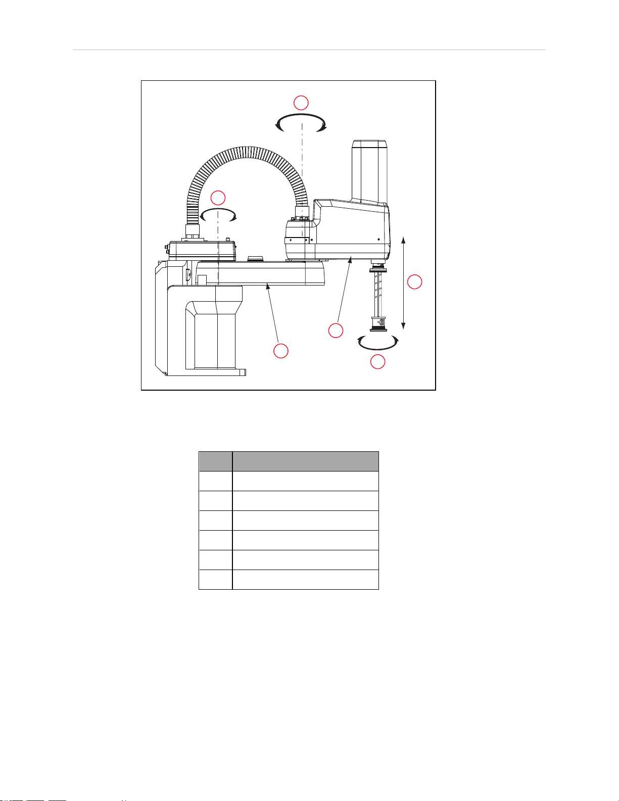
eCobra robots are four-joint SCARA industrial robots (Selective Compliance Assembly Robot
Arm). Joints 1, 2, and 4 are rotational, Joint 3 is translational. See Figure 1-2.
NOTE: The descriptions and instructions in this manual apply to the eCobra
600, eCobra 800, and eCobra 800 Inverted robots. When there are differences,
such as in dimensions and work envelopes, the different models will be covered
separately.
Chapter 1: Introduction
Figure 1-1. eCobra 800 Robot
By adding a SmartController EX or a PLC, the eCobra series robots replace the previous sCobra
and Cobra ePLC series robots, so this manual replaces previous eCobra, sCobra, and Cobra
ePLC User Guides.
14402-000 Rev. F eCobra User's Guide 11
Page 12
1.1 Product Description
1
2
6
5
4
3
Figure 1-2. Robot Joint Motions - eCobra 600 Robot Shown
Table 1-1. Robot Joint Descriptions
Item Description
1 Joint 1
2 Joint 2
3 Joint 3
4 Joint 4
5 Inner Link
6 Outer Link
eCobra Robot Models
There are three tiers of eCobra robots, with 600 and 800 mm upright models and an 800 mm
Inverted robot in each tier. In increasing order of performance and features, they are:
l
eCobra Lite
l
eCobra Standard
l
eCobra Pro
12 eCobra User's Guide 14402-000 Rev. F
Page 13
Chapter 1: Introduction
1
eCobra robots of any given size and orientation are identical physically for each of the three
tiers. The Pro models offer the fastest performance and the most features and connectivity. The
Lite models offer the least. All nine models are covered in this manual.
All eCobra robots will typically be connected to a user-supplied PC running the ACE software.
eCobra robots can optionally be used with a SmartController EX motion controller, if more features and connectivity are needed. A SmartVision MX industrial PC can be added for more vision support. The eCobra Standard and eCobra Pro robots can be used with a user-supplied
PLC and the ePLCConnect software option.
eAIB (Amplifiers in Base)
eCobra robots use an eAIB amplifier. The robots are programmed and controlled using the
eAIB. The eAIB, embedded in the robot's base, contains the amplifiers and full servo control for
the eCobra robots. The eAIB also provides the platform for running the eV+ OS and language.
eAIBFeatures
l
On-board digital I/O
l
Low EMI for use with noise sensitive equipment
l
No external fan, for quiet robot operation
l 8 kHz servo rate to deliver low positional errors and superior path following
l
Sine wave commutation to lower cogging torque and improve path following
l
Digital feed-forward design to maximize efficiency, torque, and velocity
l
Temperature sensors on all amplifiers and motors for maximum reliability and easy
troubleshooting
l
Hardware-based E-Stop and Teach Restrict controls
For improved safety relative to European standards implemented in 2012
The eAIB fits all eCobra robots.
Figure 1-3. (1) eAIB Amplifier on eCobra Robot
14402-000 Rev. F eCobra User's Guide 13
Page 14

1.2 eCobra Robot Features And Options
1.2 eCobra Robot Features And Options
The eAIB controller provides varying levels of vision support and connectivity. Some applications might call for more, in which case you could add a SmartController EX and/or a
SmartVision MX industrial PC.
Feature eCobra Lite
eCobra
Standard
eCobra Pro
SmartController
EX Option
Vision - Yes Yes -
on-the-fly - - Yes -
I/O - max
2
12/8 44/40 76/72 524/520
XIO 12/8 12/8 12/8 eAIB +12/8
IEEE1394 2 2 2 eAIB + 3
IOBlox option - 8/8 x max 4 8/8 x max 8 -
RS-422/485 - - - 1
RS-232 - 1
1
1
1
3
DeviceNet - - - Option
Conveyors
- - 2
1
4
tracked
PLC support - Yes Yes -
ePLCI/O - - Yes -
PackXpert - Yes Yes Yes
Force Sensing - Yes
1
Yes
1
-
T20 Pendant
Yes Yes Yes n/a
option
IP65 option Yes Yes Yes n/a
Cleanroom
Yes Yes Yes n/a
option
Max Robots 1 1 1 4
Dual Robots - - - Yes
Max Joints 4 4 4 16
Pass-through,
J1 to J2
1
Requires eAIB XBELT IO Adapter cable.
2
More I/Ocan be attained using DeviceNet and combinations of RS- ports, if needed.
5 air
24 user electric
1 DeviceNet
5 air
24 user electric
1 DeviceNet
5 air
24 user electric
1 DeviceNet
-
14 eCobra User's Guide 14402-000 Rev. F
Page 15

Chapter 1: Introduction
SmartController EX
The SmartController EX motion controller can coordinate up to 4 robots, increasing the number
of robot joints to 16 from the eCobra’s 4. It increases the I/O available, raises the number of
serial ports by 3, and provides for tracking up to 4 additional conveyors.
NOTE: Since the eAIB has only one RS-232 port, adding a SmartController EX to
the RS-232 port renders the port unusable. If using eV+, "SERIAL:0" will access
the eAIB's RS-232 port.
TheSmartController EX supports the DeviceNet option, and allows for the use of third-party
vision systems. One RS-485 port is available.
The SmartController EX is covered in the SmartController EX User's Guide.
ePLC Connect Software
The ePLC Connect software allows programming and operation of an eCobra robot directly
from a PLC, using the software as an interface between the PLC and the robot. Refer to ePLC
Connect 3.0 Software User's Guide.
IO Blox
Up to 8 IO Blox units can be added to increase the available I/O ports by 8 inputs and 8 outputs per unit. The IOBlox does not require a SmartController EX. Refer to the IO Blox User’s
Guide.
SmartVision MX
The SmartVision MX is an industrial PC that provides vision-oriented connectivity, as well as
extra I/O. It can drive up to 4 Gigabit and 4 USB 3.0 cameras. The Gigabit ports are PoE, so no
extra power is needed to the cameras. Refer to the SmartVision MX User's Guide.
T20 Pendant
The T20 pendant provides manual control of an eCobra robot. This is generally used when
teaching pick and place locations. Refer to the T20 Pendant User's Guide.
NOTE: Omron Adept Technologies, Inc. does not offer a cableless (wireless)
pendant.
Intelligent Force Sensing
The Intelligent Force Sensing system is a hardware and software package that allows eCobra
robots to react to sensed forces and moments at the tool flange, reducing force overshoot and
stopping time when forces or moments exceed preset thresholds. Refer to the Intelligent Force
Sensing System User's Guide.
ACE PackXpert Process Manager
PackXpert provides a point-and-click interface for configuring and programming the workcell.
The PackXpert Process Manager is the recommended method for programming most applications. Refer to the ACE User’s Guide.
14402-000 Rev. F eCobra User's Guide 15
Page 16
1.3 How Can I Get Help?
1.3 How Can I Get Help?
Refer to the corporate website:
http://www.ia.omron.com
Related Manuals
This manual covers the installation, operation, and maintenance of an eCobra robot system.
For additional manuals covering programming the system, reconfiguring installed components, and adding optional components, see the following table.
Manual Title Description
Robot Safety Guide Contains safety information for robots.
ACE User’s Guide Instruction for the use of the ACE software.
Table 1-2. Related Manuals
SmartController EX User's
Guide
SmartVision MX User's Guide Instructions for use of the optional SmartVision MX indus-
T20 Pendant User's Guide Describes the use of the optional T20 manual control
IO Blox User’s Guide Describes the IO Blox product.
Single and Multiple Robot Configuration Guide
Instructions for use of the optional SmartController EX
motion controller.
trial PC.
pendant.
Contains cable diagrams and configuration procedures for a
single and multi-robot system.
16 eCobra User's Guide 14402-000 Rev. F
Page 17
2.1 Dangers, Warnings, and Cautions
!
!
!
!
!
Alert Levels
There are three levels of alert notation used in our manuals. In descending order of importance, they are:
DANGER: Identifies an imminently hazardous situation which, if not
avoided, is likely to result in serious injury, and might result in fatality or
severe property damage.
WARNING: Identifies a potentially hazardous situation which, if not avoided,
will result in minor or moderate injury, and might result in serious injury, fatality, or significant property damage.
CAUTION: Identifies a potentially hazardous situation which, if not avoided,
might result in minor injury, moderate injury, or property damage.
Chapter 2: Safety
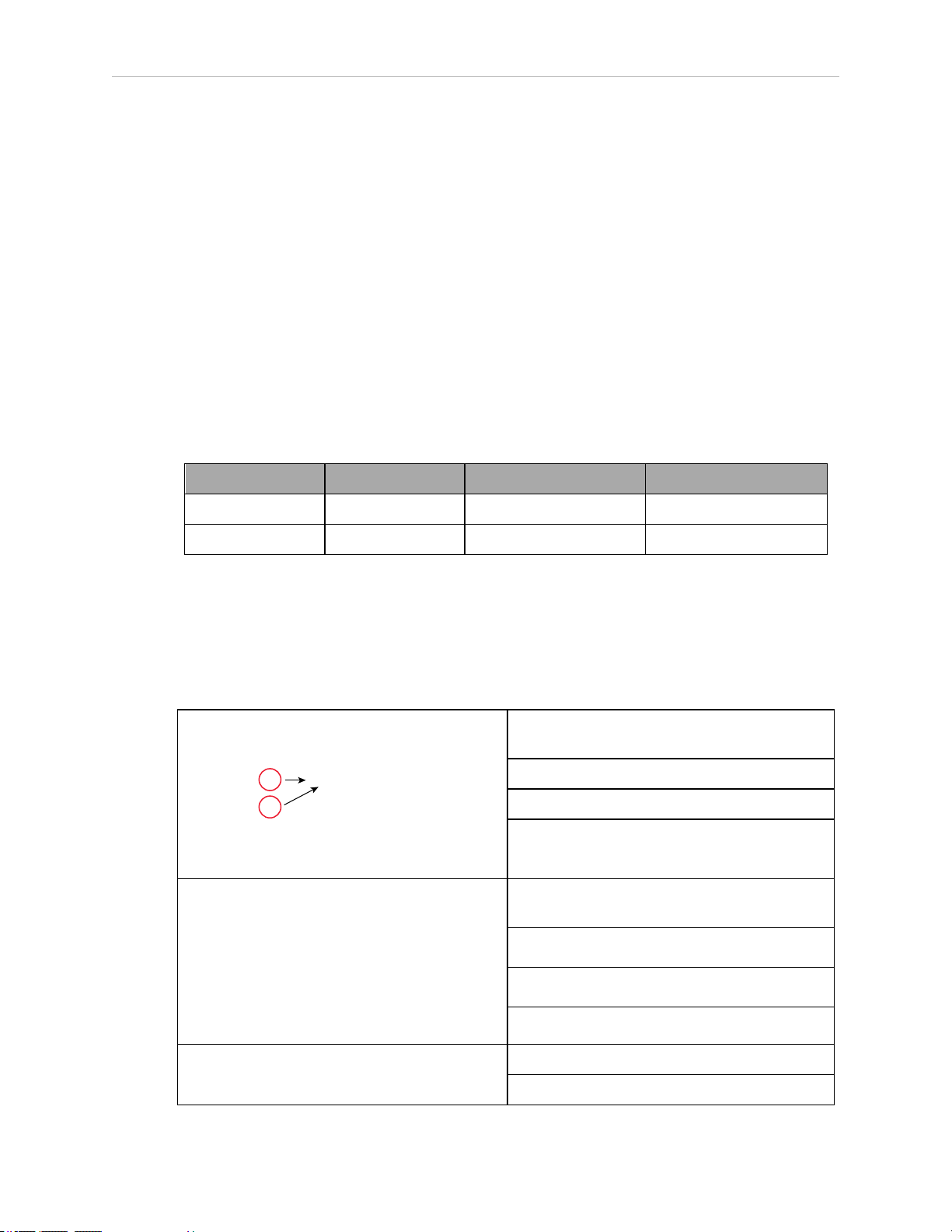
Alert Icons
The icon that starts each alert can be used to indicate the type of hazard. These will be used
with the appropriate signal word - Danger, Warning, or Caution - to indicate the severity of the
hazard. The text following the signal word will specify what the risk is, and how to avoid it.
Icon Meaning Icon Meaning
This is a generic alert
icon. Any specifics on
the risk will be in the
text following the signal word.
Falling Hazards
WARNING: PERSONALINJURYORPROPERTYDAMAGERISK
If mounted incorrectly, the robot can fall over and cause serious injury to personnel or damage to itself or other equipment.
This identifies a hazardous electrical situation.
14402-000 Rev. F eCobra User's Guide 17
Page 18
2.2 What to Do in an Emergency/Abnormal Situation
!
!
Safety Barriers
To protect personnel from coming in contact with robot unintentionally or objects entering
robot’s operation zone, install user-supplied safety barriers in the workcell.
Special Information
There are several types of notation used to call out special information.
IMPORTANT: Information to ensure safe use of the product.
NOTE: Information for more effective use of the product.
Additional Information: Offers helpful tips, recommendations, and best prac-
tices.
Version Information: Information on differences in specifications for different
versions of hardware or software.
2.2 What to Do in an Emergency/Abnormal Situation
Press any E-Stop button (a red push-button on a yellow background) and then follow the
internal procedures of your company or organization for an emergency situation. If a fire
occurs, use a type D extinguisher: foam, dry chemical, or CO2.
Releasing the Brakes
In case of entrapment of a person by the robot, or any other emergency of abnormal situation,
the robot can be manually moved to a safe state without high voltage electric power. However
only qualified personnel who have read and understood this manual and the Robot Safety
Guide should manually move the robot. See Brake Release Button on page 80.
WARNING: PERSONALINJURYRISK
eCobras are not collaborative robots. They require a dedicated work area that
will prevent personnel from coming into contact with them during operation.
Releasing an E-Stop
CAUTION: PERSONALINJURYORPROPERTYDAMAGERISK
If the robot’s E-Stop is triggered, ensure that the cause of the E-Stop is resolved,
and all surrounding areas are clear before releasing the E-Stop.
After the E-Stop button has been manually released, the robot will wait until the motors are
manually enabled.
There are two ways to enable the motors:
l
Enable power through ACE software installed on your PC.
ll
Press the ROBOTPOWER button on the Pendant.
18 eCobra User's Guide 14402-000 Rev. F
Page 19
Chapter 2: Safety
!
Once the motors are enabled, the robot will wait two seconds and then resume commanded
motion, if there is adequate space to maneuver.
Emergency Stop Circuit and Buttons
The E-Stop provided complies with ISO 10218-1 (Clause 5.5.2), with stop category 1 (per IEC
60204). The E-stop button complies with ISO 13850. The E-Stop meets the requirements of PL-d
per ISO 13849.
If you design your own front panel, it must meet the requirements of ISO13849, and be at least
PL-d. The E-Stop button must comply with IEC 60204-1 and ISO13850, Clause 5.5.2.
If you choose to use your own E-Stop buttons, they must meet the requirements of IEC 60204-1
and ISO 13850, Clause 5.5.2.
General Hazards
IMPORTANT: The following situations could result in injury or damage to the
equipment.
l
Do not place objects on the robot.
l
Do not exceed the maximum payload capacity.
l
Do not exceed the maximum recommended moment of Inertia, speed, and rotation limits. See Technical Specifications on page 153.
l
Do not drop the robot, put weights on it or otherwise operate it irresponsibly.
l
Do not use unauthorized parts.
2.3 Safety Precautions
WARNING: PERSONALINJURYORPROPERTYDAMAGERISK
An eCobra robot can cause serious injury or death, or damage to itself and
other equipment, if the safety precautions in this manual are not observed.
WARNING: ELECTROCUTIONRISK
During maintenance, disconnect AC power from the robot, and install a lockout tag-out to prevent anyone from reconnecting power.
User's Responsibilities
Safe use of the eCobra robot is your responsibility. To ensure compliance with safety rules and
regulations:
l
All personnel who install, operate, teach, program, or maintain an eCobra robot system
must read this guide, read the Robot Safety Guide, and complete a training course for
their responsibilities in regard to the robot.
14402-000 Rev. F eCobra User's Guide 19
Page 20

2.3 Safety Precautions
l
All personnel who design an eCobra robot system must read this guide, read the Robot
Safety Guide, and must comply with all local and national safety regulations for the location in which the robot is installed.
Figure 2-1. Read Manual and Impact Warning Labels
l
The eCobra robot system must not be used for purposes other than described in Intended Use on page 21. Contact Omron Adept Technologies, Inc. if you are not sure of the
suitability for your application.
l The environment must be suitable for safe operation of the robot.
l
The user is responsible for providing safety barriers around the robot to prevent anyone
from accidentally coming into contact with the robot when it is in motion.
l
Power to the robot and its power supply must be locked out and tagged out before any
maintenance is performed.
l
The eCobra Robots must be well maintained, so that their control and safety functions
continue to work properly.
Qualification of Personnel
It is the end-user’s responsibility to ensure that all personnel who will work with or around
robots have attended an appropriate Omron training course and have a working knowledge of
the system. The user must provide the necessary additional training for all personnel who will
be working with the system.
As noted in this and the Robot Safety Guide, certain procedures should be performed only by
skilled or instructed persons. For a description of the level of qualification, we use the standard
terms:
l
Skilled persons have technical knowledge or sufficient experience to enable them to
avoid the dangers, electrical and/or mechanical
l
Instructed persons are adequately advised or supervised by skilled persons to enable
them to avoid the dangers, electrical and/or mechanical
All personnel must observe industry-prescribed safety practices during the installation, operation, and testing of all electrically-powered equipment.
IMPORTANT: Before working with the robot, every entrusted person must confirm that they:
l
Have the necessary qualifications
l
Have received the guides (both this user’s guide, and the Robot Safety Guide)
20 eCobra User's Guide 14402-000 Rev. F
Page 21
l
!
Have read the guides
l
Understand the guides
l
Will work in the manner specified by the guides
2.4 Robot Behavior
Hardstops
If the eCobra Robot runs into one of its hardstops, the robot`s motion will stop completely, an
envelope error will be generated, and power will be cut to the robot motors. The robot cannot
continue to move after hitting a hardstop until the error has been cleared.
The eCobra’s hardstops are capable of completely stopping the robot at any speed, load, and
maximum or minimum extension.
Limiting Devices
There are no dynamic or electro-mechanical limiting devices provided by Omron Adept Technologies, Inc. The robot does not have safety-rated soft axis or space limiting.
Chapter 2: Safety
However, the user can install their own safety rated (category 0 or 1) dynamic limiting devices
if needed, that comply with ISO10218-1, Clause 5.12.2.
Singularities
No singularities exist that cause a hazardous situation with an eCobra robot.
2.5 Intended and Non-intended Use
Intended Use
The normal and intended use of these robots does not create hazards. The eCobra robots have
been designed and constructed in accordance with the relevant requirements of IEC60204-1.
The eCobra robots are intended for use in parts assembly and material handling for payloads
less than 5.5 kg (12.1 lb). See Robot Specifications on page 166 for complete information on the
robot specifications. Refer to the Robot Safety Guide for details on the intended use of eCobra
robots.
WARNING: PERSONALINJURYRISK
eCobra robots are not collaborative robots. They require a dedicated work area
that will prevent personnel from coming into contact with them during operation.
Guidelines for safe use:
l
Clean, dry mounting surfaces — surfaces that are routinely kept free of debris and
liquids.
14402-000 Rev. F eCobra User's Guide 21
Page 22

2.6 Additional Safety Information
l
Temperature — 5 to 40°C (41 to 104°F), with a recommended humidity range of 5% to
90%, non-condensing.
Non-Intended Use
The eCobra robots are not intended for use in any of the following situations:
l
Use in the presence of ionizing or non-ionizing radiation
l
Use in potentially explosive atmospheres
l
Use in medical or life saving applications
l
Use in a residential setting. They are for industrial use only
l
Use before performing a risk assessment
l
Where the equipment will be subject to extremes of heat or humidity
IMPORTANT: The instructions for operation, installation, and maintenance given in this guide and Robot Safety Guide must be strictly
observed.
Non-intended use of eCobra robots can:
l
Cause injury to personnel
l
Damage itself or other equipment
l
Reduce system reliability and performance
If there is any doubt concerning the application, ask your your local Omron support to determine if it is an intended use or not.
Robot Modifications
If the user or integrator makes any changes to the robot, it is their responsibility to ensure that
there are no sharp edges, corners, or protrusions.
Note that any change to the robot can lead to loss in safety or functionality. The user or integrator must ensure that all safety features are operational after modifications.
2.6 Additional Safety Information
Contact your local Omron support for other sources of safety information:
Manufacturer’s Declaration of Incorporation
This lists all standards with which the robot complies. The Manufacturer’s Declarations for
the eCobra robot and other products are in the Manufacturer's Declarations.
22 eCobra User's Guide 14402-000 Rev. F
Page 23

Chapter 2: Safety
Robot Safety Guide
The Robot Safety Guide, which ships with every robot system, provides detailed information
on safety for Omron Adept Technologies, Inc. robots. It also gives resources for information on
relevant standards.
T20 Manual Control Pendant (Option)
The protective stop category for the pendant enable switch is category 1, which complies with
the requirements of ISO 10218-1. The pendant is designed in accordance with the requirements
of IEC 60204-1 and ISO 13849. The E-Stop button is ISO 13850 compliant.
NOTE: Omron Adept Technologies, Inc. does not offer a cableless
(wireless)pendant.
The manual control pendant can only move one robot at a time, even if multiple robots are
connected to a SmartController EX, and the pendant is connected to the SmartController EX.
Disposal
Dispose of in accordance with applicable regulations.
Customers can contribute to resource conservation and protecting the environment by the
proper disposal of WEEE (Waste Electronics and Electrical Equipment). All electrical and electronic products should be disposed of separately from the municipal waste system via designation collection facilities. For information about disposal of your old equipment, contact
your local Omron support.
14402-000 Rev. F eCobra User's Guide 23
Page 24

Page 25
3.1 Installation Overview
The system installation process is summarized in the following table.
NOTE: For multi-robot installations, see the Single and Multiple Robot Con-
figuration Guide.
Task to be Performed Reference Location
Mount the robot to a flat, secure mounting surface. See Mounting an Upright eCobra
Chapter 3: Robot Installation
Table 3-1. Installation Overview
Robot on page 27 or Mounting an eCobra 800 Inverted Robot on page 30.
Install the Front Panel, pendant, and ACE software.
The pendant is an option.
Create a 24 VDC cable and connect it between the
robot and the user-supplied 24 VDC power supply.
Create a 200-240 VAC cable and connect it between
the robot and the facility AC power source.
Install user-supplied safety barriers in the workcell. See Installing User-Supplied Safety
Learn about connecting digital I/O through the XIO
connector on the eAIB.
Learn about starting the system for the first time. See Starting the System for the First
Learn about installing optional equipment, including end-effectors, user air and electrical lines,
external equipment, solenoids, etc.
3.2 Transport and Storage
This equipment must be shipped and stored in a temperature-controlled environment, within
the range –25 to +60° C (-13 to +140° F). The recommended humidity range is 5% to 90%, noncondensing. It should be shipped and stored in the supplied crate, which is designed to prevent damage from normal shock and vibration. You should protect the crate from excessive
shock and vibration.
See System Installation on page 35.
See Connecting 24 VDC Power to
Robot on page 50.
See Connecting 200-240 VAC Power to
Robot on page 54.
Equipment on page 62.
See eAIB XIO Connector Signals on
page 86.
Time on page 94.
See Optional Equipment Installation
on page 123.
Use a forklift or pallet jack to transport the packaged equipment. See Figure 3-1.
14402-000 Rev. F eCobra User's Guide 25
Page 26
3.3 Unpacking and Inspecting the Equipment
!
The robots must always be stored and shipped in an upright position in a clean, dry area that
is free from condensation. Do not lay the crate on its side or any other non-upright position;
this could damage the robot.
The eCobra 600 robot weighs 41 kg (90 lb), the eCobra 800 robot weighs 43 kg (95 lb), and the
eCobra 800 Inverted weighs 51 kg (112 lb), all with no options installed.
3.3 Unpacking and Inspecting the Equipment
Before Unpacking
Carefully inspect all shipping crates for evidence of damage during transit. Pay special attention to any tilt and shock indication labels on the exteriors of the containers. If any damage is
indicated, request that the carrier’s agent be present at the time the container is unpacked.
Upon Unpacking
Before signing the carrier’s delivery sheet, please compare the actual items received (not just
the packing slip) with your equipment purchase order and verify that all items are present and
that the shipment is correct and free of visible damage.
l
If the items received do not match the packing slip, or are damaged, do not sign the
receipt. Contact Omron Adept Technologies, Inc. as soon as possible.
l
If the items received do not match your order, please contact Omron Adept Technologies, Inc. immediately.
Inspect each item for external damage as it is removed from its container. If any damage is
evident, contact Omron Adept Technologies, Inc.. See How Can I Get Help? on page 16.
Retain all containers and packaging materials. These items may be necessary to settle claims
or, at a later date, to relocate equipment.
3.4 Repacking for Relocation
If the robot or other equipment needs to be relocated, reverse the steps in the installation procedures that follow. Reuse all original packing containers and materials and follow all safety
notes used for installation. Improper packaging for shipment will void your warranty. Specify
this to the carrier if the robot is to be shipped.
CAUTION: PROPERTYDAMAGERISK
Before unbolting the robot from the mounting surface, fold the outer arm
against the Joint 2 hardstops to help centralize the center of gravity. The robot
must always be shipped in an upright orientation.
26 eCobra User's Guide 14402-000 Rev. F
Page 27
3.5 Environmental and Facility Requirements
1
2
The robot system installation must meet the operating environment requirements shown in the
following table.
Table 3-2. Robot System Operating Environment Requirements
Ambient temperature 5 to 40° C (41 to 104° F)
Shipping/storage temperature –25 to 55° C (-13 to 131° F)
Humidity 5% to 90%, non-condensing
Altitude up to 2000 m (6500 ft)
Pollution degree 2
Robot protection class IP20 (NEMA Type 1)
IP65 Versions IP65
Cleanroom rating, cleanroom models only ISO 4, Fed Reg Class 10
Chapter 3: Robot Installation
NOTE: For robot dimensions, see Dimension Drawings on page 153.
3.6 Mounting an Upright eCobra Robot
This section applies to the eCobra 600 and eCobra 800 robots, but not the eCobra 800 Inverted
robot.
Figure 3-1. eCobra 800 Robot on a Transportation Pallet
14402-000 Rev. F eCobra User's Guide 27
Page 28
3.6 Mounting an Upright eCobra Robot
!
+0.015
6
2x R4
0
45
50
10
160
160
200
80
90
+0.015
0
Ø 8
4X
Ø 14 THRU
6
234
338
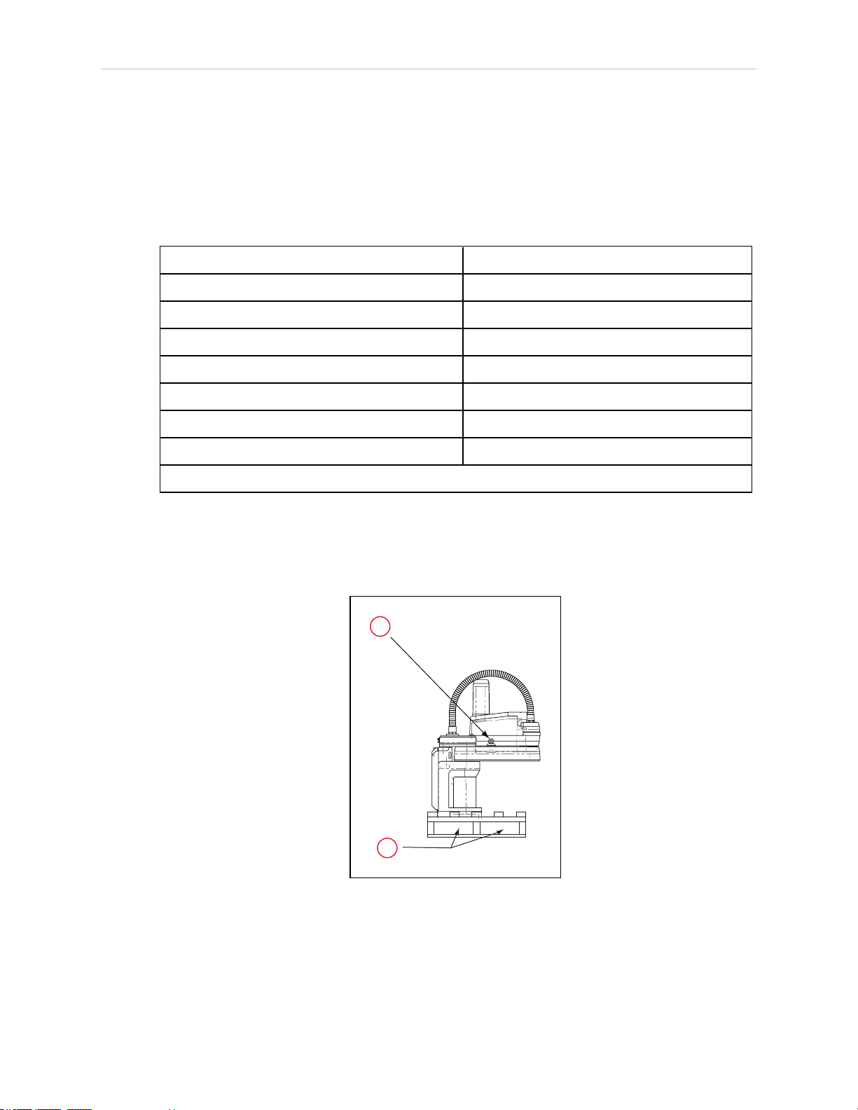
Table 3-3. Lifting Points for Robot while on a Transportation Pallet
Item Description
1 Eyebolt for lifting robot after robot has been unbolted from the transportation pallet.
2 Place for forklift or pallet-jack here.
WARNING: PERSONALINJURYORPROPERTYDAMAGERISK
Only qualified service personnel may install or service the robot system.
Mounting Surface
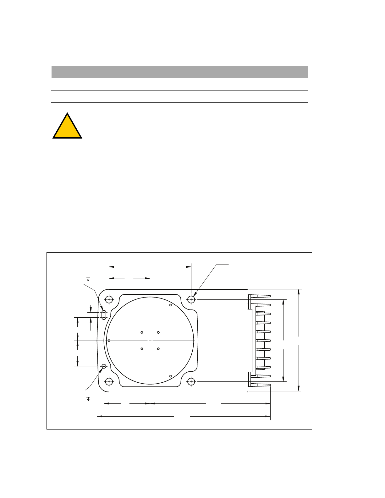
The upright eCobra robots are designed to be mounted on a smooth, flat, level surface. The
mounting structure must be rigid enough to prevent vibration and flexing during robot operation. We recommend a 25 mm (1 in.) thick steel plate mounted to a rigid tube frame. Excessive vibration or mounting flexure will degrade robot performance. The following figure shows
the mounting hole pattern for the eCobra robots.
NOTE: On the under side of the base there is a hole and a slot that can be used
as locating points for user-installed dowel pins in the mounting surface; see the
following figure. Using locating pins will improve the ability to remove and reinstall the robot in the same position.
Figure 3-2. Mounting Hole Pattern for Upright eCobra Robots (Units in mm)
28 eCobra User's Guide 14402-000 Rev. F
Page 29
Mounting Procedure
!
!
1.
Using the dimensions shown in the previous figure, drill and tap the mounting surface
for four M12 - 1.75 x 36 mm (or 7/16 - 14 UNC x 1.50 in.) machine bolts (mounting hardware is user-supplied).
2.
If you are using dowel pins for locating the robot, insert those in the mounting surface.
3.
While the robot is still bolted to the transportation pallet, connect a hydraulic lift to the
eyebolt at the top of the inner link. See Figure 3-1.
4.
Remove the four bolts securing the robot base to the pallet.
Retain these bolts for possible later relocation of the equipment.
Chapter 3: Robot Installation
WARNING: PERSONALINJURYORPROPERTYDAMAGERISK
Do not attempt to lift the robot at any points other than the eyebolt
provided. Do not attempt to extend the inner or outer links of the robot
until the robot has been secured in position. Failure to comply could result in the robot falling and causing either personnel injury or equipment
damage.
5.
Lift the robot and position it directly over the mounting surface.
6.
Slowly lower the robot while aligning the base and the tapped holes in the mounting
surface.
NOTE: The base casting of the robot is aluminum and can easily be dented if
bumped against a harder surface.
7.
Verify that the robot is mounted squarely (cannot rock back and forth) before tightening
the mounting bolts.
8.
Install the user-supplied mounting bolts and washers. Tighten bolts to the torque specified in the following table.
WARNING: PERSONALINJURYORPROPERTYDAMAGERISK
The center of mass of the robot may cause the robot to fall over if the
robot is not secured with the mounting bolts.
NOTE: Check the tightness of the mounting bolts one week after initial installation, and then recheck every 6 months. See Maintenance on page 99 for periodic
maintenance.
Table 3-4. Mounting Bolt Torque Specifications
Standard Size Specification Torque
Metric M12 x 1.75 ISO Property Class 8.8 85 N·m
SAE 7/16-14 UNC SAE J429 Grade 5 or
ASTM A449
14402-000 Rev. F eCobra User's Guide 29
65 ft-lb
Page 30
3.7 Mounting an eCobra 800 Inverted Robot
45
50
10
80
107
90
160
205
160
189
4X Ø 14 Thru
Ø 8
2X R 4
+ 0.015
0.000
+ 0.015
0.000
6
6
3.7 Mounting an eCobra 800 Inverted Robot
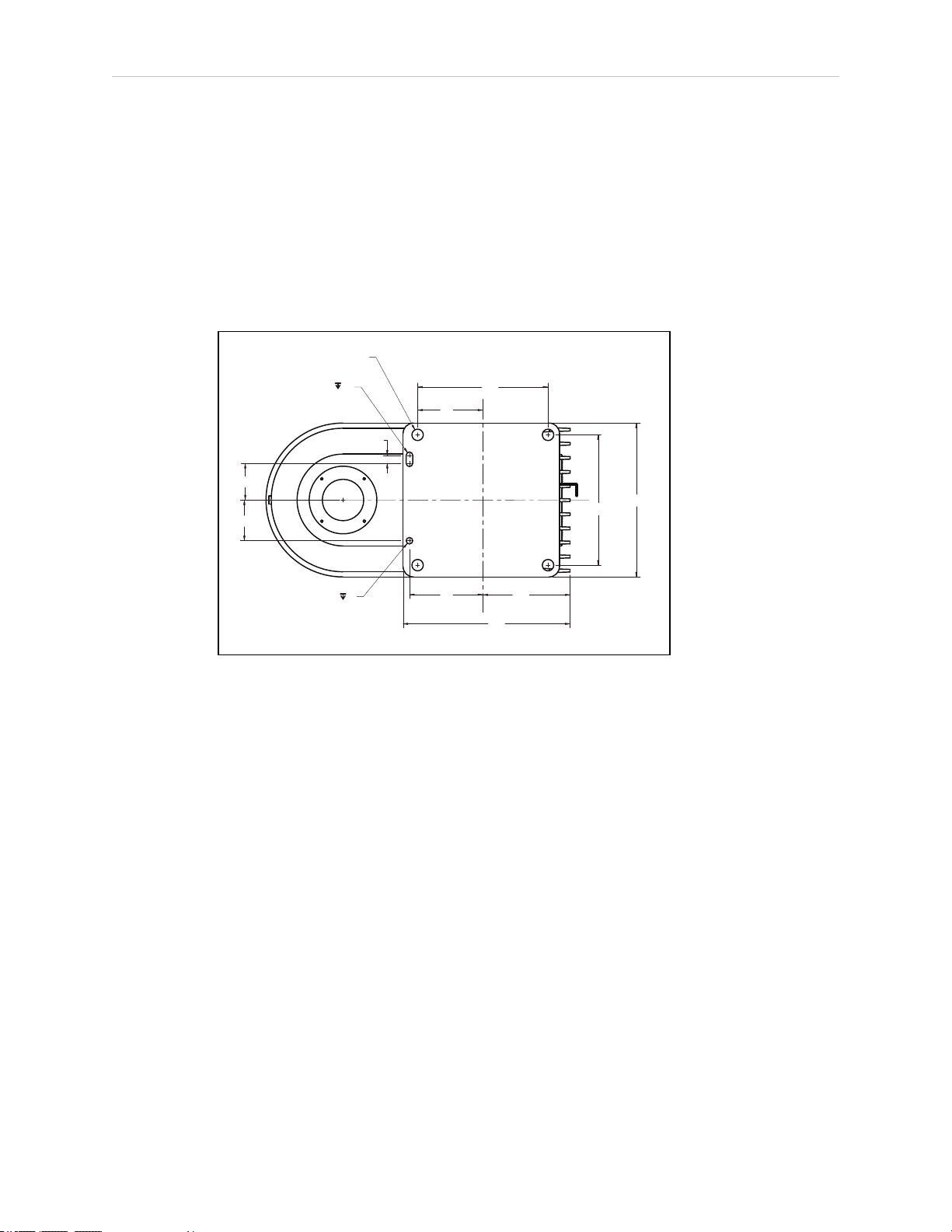
Mounting Surface
The eCobra 800 Inverted robot is designed to be mounted in an inverted position. When designing the mounting structure, you must account for both load and stiffness. The mounting structure must be rigid enough to prevent vibration and flexing during robot operation. Excessive
vibration or mounting flexure will degrade robot performance. The mounting structure should
be stiff enough so that the first vibration mode is greater than 70 Hz.
The following figure shows the mounting hole pattern.
Figure 3-3. Robot Mounting Dimensions for eCobra Inverted Robot (Units in mm)
NOTE: On the robot mounting surface, there is a hole and a slot that can be
used as locating points for user-installed dowel pins in the mounting surface.
Using locating pins can improve the ability to remove and reinstall the robot in
the same position.
Mounting Procedure
l
Always use at least two people, and preferably three, to mount the robot.
l
The robot should be in the folded position when lifting. See the following figure.
30 eCobra User's Guide 14402-000 Rev. F
Page 31

Chapter 3: Robot Installation
183.2
278
500
778
!
1
Figure 3-4. Robot in Folded Position (Units in mm)
WARNING: PERSONALINJURYORPROPERTYDAMAGERISK
Do not attempt to extend the inner or outer links of the robot until the robot has
been secured in position. Failure to comply could result in the robot falling and
causing either personnel injury or equipment damage.
1.
Using the dimensions shown in Figure 3-3. , drill and tap the mounting surface for four
M12 - 1.75 x 36 mm (or 7/16 - 14 UNC x 1.50 in.) machine bolts (mounting hardware is
user-supplied).
2.
If you are using dowel pins for locating the robot, insert those in the mounting surface.
3.
Remove the four screws on top of the wooden robot base protection box. See Figure 3-5.
l
Remove the robot base protection box.
l
Retain the four screws and box for possible later relocation of the equipment.
Figure 3-5. Pallet Lifting Device (1) Insertion Point
14402-000 Rev. F eCobra User's Guide 31
Page 32

3.8 Mounting the Front Panel
!
!
4.
While the robot is still bolted to the transportation pallet, use a forklift or other mechanical lifting device to lift the robot and position it directly under the mounting surface.
Make sure that one person watches the robot carefully as it is lifted and transported, to
ensure it does slip or become unbalanced.
WARNING: PERSONALINJURYORPROPERTYDAMAGERISK
The center of mass of the robot may cause the robot to fall over if the
robot is not secured to the pallet.
5.
Slowly lift the robot while aligning the base and the tapped mounting holes in the
mounting surface.
6.
Install, but do not tighten, the user-supplied mounting bolts and washers.
CAUTION: PROPERTYDAMAGERISK
The base casting of the robot is aluminum and can easily be dented if
bumped against a harder surface.
NOTE: Verify that the robot is mounted squarely (will not rock back and forth)
before tightening the mounting bolts.
7.
Remove the bolts securing the robot to the pallet.
l
Retain these bolts for possible later relocation of the equipment.
l
Move the pallet out of the way.
8.
Tighten the mounting bolts to the torque specified.
Table 3-5. Mounting Bolt Torque Specifications
Standard Size Specification Torque
Metric M12 x 1.75 ISO Property Class 8.8
SAE 7/16-14 UNC SAE J429 Grade 5 or
NOTE: Check the tightness of the mounting bolts one week after installation,
and then recheck every 6 months. See Maintenance on page 99 for periodic maintenance.
3.8 Mounting the Front Panel
The Front Panel must be installed outside of the workspace.
85 N·m
65 ft-lbf
ASTM A449
NOTE: European standards require that the remote High Power push-button be
located outside of the workspace of the robot.
32 eCobra User's Guide 14402-000 Rev. F
Page 33

3.9 Connectors on Robot Interface Panel (eAIB)
DC
IN
24
V
GND
A
C 1Ø
200-240 V
XBELTIO
XIO
Servo
ENETENET
XSYSTEM
24 VDC—for connecting user-supplied 24 VDC power to the robot. The mating connector is
provided.
Ground Point—for connecting cable shield from user-supplied 24 VDC cable.
200/240 VAC — for connecting 200-240 VAC, single-phase, input power to the robot. The mat-
ing connector is provided. The cable is user-supplied.
XIO (DB26, high density, female) — for user I/O signals for peripheral devices. This connector
provides 8 outputs and 12 inputs. For connector pin allocations for inputs and outputs, see
eAIB XIO Connector Signals on page 86. That section also contains signal numbers to access
these I/O signals via eV+.
XBELTIO — (this is not supported on eCobra Lite robots) adds two belt encoders (Pro only),
an RS-232 interface, and either Intelligent Force Sensing or IO Blox support. This requires the
eAIB XBELT IO Adapter cable.
SmartServo x2 (IEEE1394) — for connecting the IEEE 1394 cable from an optional controller to
the robot. The servo connectors can also be used to connect to a second robot or another 1394based motion axis.
Chapter 3: Robot Installation
XSYSTEM — The Front Panel, optional T20 pendant, and XUSR cable connect here. This uses
the eAIB XSYSTEM cable. See System Cables, without SmartController EX on page 35.
If you are using an optional SmartController EX, it uses the eAIB XSYS cable, instead of this
cable, and the Front Panel and T20 pendant connect to the SmartController EX.
ENET — Two Ethernet ports are available. One will be needed to connect to a PC running
ACE software or a user-supplied PLC.
Figure 3-6. Robot Interface Panel
14402-000 Rev. F eCobra User's Guide 33
Page 34

Page 35

Chapter 4: System Installation
DC
IN
24 V
GND
AC
200 -
240 V
Ø
1
XBELTIO
XIO
Servo
ENETENET
XSYSTEM
XMCP
XFP
XUSR
B
P
O
N
L
J
I
H
G
F
E
D
C
T
S
R
A
U
200 - 240 VAC
2
2a
3
3a
4
4
4b
4a
5
7
8
8a
9
10
1
3
K
M
K
6
11
12
eCobra Robot
Q
V
W
SmartVision MX
DC
IN
24V
GND
AC
200 240V
Ø
1
XBELTIO
XIO
Servo
ENETENET
XSYSTEM
This chapter does not cover I/O. Refer to Connecting Digital I/O to the System on page 83.
4.1 System Cables, without SmartController EX
The letters in the following figure correspond to the letters in Table 4-1. Cables and Parts
Description (without SmartController EX). The numbers in the following figure correspond to
the numbers in Table 4-2. Connections Installation Steps.
Figure 4-1. System Cable Diagram for eCobra Robots, Pendant and Vision Shown
14402-000 Rev. F eCobra User's Guide 35
Page 36

4.1 System Cables, without SmartController EX
The figure above includes the optional T20 pendant, optional SmartVision MX industrial PC,
and optional PLC. These items may not be present in your system.
NOTE: For additional system grounding information, see Connecting 24 VDC
Cable on page 52.
List of Cables and Parts
Open the Accessory box and locate the eAIB XSYSTEM cable. Connect the cables and peripherals as shown in the preceding figure. Installation steps are covered in Cable Installation
Overview on page 38.
Table 4-1. Cables and Parts Description (without SmartController EX)
Item Description Part #
A eAIB XSYSTEM Cable
Assembly
B User E-Stop, Safety
Gate
C XUSR Jumper Plug 04736-
D Front Panel 90356-
E Front Panel Cable 10356-
F Front Panel Jumper
Plug
13323000
n/a X
000
10358
10500
10053000
Standard Option
X
X Required if no
X X Front Panel (D)
X X
X Front Panel (D)
User-
supplied
Notes
E-stop, safety
gate or muted
safety gate
used.
or Front Panel
Jumper Plug (F)
must be used.
or Front Panel
Jumper Plug (F)
must be used.
G XMCP Jumper Plug 10052-
000
H T20 Pendant Bypass
Plug
10048000
X XMCPJumper
Plug (G), T20
Pendant
Bypass Plug
(H), or T20
Pendant
Assembly
(W)must be
used.
X XMCPJumper
Plug (G), T20
Pendant
36 eCobra User's Guide 14402-000 Rev. F
Page 37

Chapter 4: System Installation
Item Description Part #
I T20 Pendant Adapter
Cable
The following three items are available, as an option, in the power supply/cable kit 90565-010
J VAC Power Cable 04118-
K 24 VDC Power Cable 04120-
L 24 VDC, 6 A Power
Supply
M Ethernet Cable -
switch -> eAIB
N Ethernet Cable -
switch ->
SmartVisionMX
10051003
000
000
04536000
n/a X
n/a X
Standard Option
X
X X 200-240 VAC,
X X
X X 85-264 VAC
User-
supplied
Notes
Bypass Plug
(H), or T20
Pendant
Assembly (W)
must be used.
single phase
universal input
O Ethernet switch n/a X
P Camera and cable n/a X X
Q Ethernet Cable -
switch - > PLC (only
while programming
PLC)
R Robot Interface Panel n/a X
S User-supplied ground
wire
T PCrunning
ACESoftware
U Ethernet Cable - PC->
ethernet switch
V PLC(optional) X
W T20 Pendant
Assembly
n/a X
n/a X
n/a X
10054010
X X
X Optional T20
Pendant Kit
(10046- 010)
includes items
W, H, and I.
14402-000 Rev. F eCobra User's Guide 37
Page 38

4.1 System Cables, without SmartController EX
!
The XUSR, XMCP, and XFP jumpers intentionally bypass safety connections so you can test
the system functionality during setup.
WARNING: PERSONALINJURYRISK
Under no circumstances should you run an eCobra system, in production
mode, with all three jumpers installed. This would leave the system with no EStops.
Cable Installation Overview
Table 4-2. Connections Installation Steps
Step Connection Description Item
1 Connect eAIB XSYSTEM cable to XSYSTEM on eMB-40R. A, R
2 Connect a user E-Stop or Muted Safety Gate to the eAIB XSYSTEM cable
XUSR connector or verify XUSR jumper plug (2a) is installed in eAIB
XSYSTEM cable XUSR connector.
Refer to Installing User-Supplied Safety Equipment on page 62 for more
information.
3 Connect Front Panel cable to Front Panel and eAIB XSYSTEM cable XFP con-
nector.
If no Front Panel is used, install FP jumper (3a) on eAIB XSYSTEM cable XFP
connector. See NOTE after table.
4 Connect T20 adapter cable and the T20 Pendant to eAIB XSYSTEM cable
XMCP connector.
If no T20 Pendant, install XMCP jumper (4a) or T20 Adapter Cable with T20
bypass plug (4b).
5 Connect user-supplied ground.
Refer to Grounding the Robot System on page 59 for more information.
6 Connect Ethernet cable from PLCto switch, if a PLCis used.
Refer to Configuring a PLC on page 60 for more information.
7 Connect 200-240 VAC to VAC Input on eAIB Interface Panel; secure with
clamp.
B, C
D, E, F
G or H,
I, T20
Pendant
S
Q
J, R
Refer to System Installation on page 35 for more information.
8 Connect 24 VDC to DC Input on Interface Panel.
Connect 24 VDC and shield ground to SmartVision MX, if used (8a). See
SmartVision MX user's guide for location.
Refer to Connecting 24 VDC Power to Robot on page 50 for more information.
9 Connect Ethernet cable from switch to eAIB. M, O, R
K, L, R
38 eCobra User's Guide 14402-000 Rev. F
Page 39

Chapter 4: System Installation
Step Connection Description Item
10 Connect Ethernet cable from switch to SmartVision MX, if used. N, O
11 Connect optional camera and cable to SmartVision MX, if used. P
12 Connect Ethernet cable from PC to switch if used. T, U
NOTE: A front panel ships with each eCobra robot system, but you can choose
not to use it if you replace its functionality with equivalent circuits. That is beyond the scope of this guide.
14402-000 Rev. F eCobra User's Guide 39
Page 40

4.2 System Cables, with SmartController EX
SmartController EX
COM1
COM2
MOUSE
KEYBD
DVI
VGA
LAN1
USB
LAN2
USB
LOUT
LIN
MIC
POWER
HDD SYS
24VCD 6A
_
+
SmartVision EX
SmartVision MX
eCobra Robot
200-240 VAC
10 A
DC
IN
24V
GND
AC
200 -
240V
Ø
1
XBELTIO
XIO
Servo
ENETENET
XSYSTEM
U
V
DC
IN
24 V
GND
AC
200 240 V
Ø
1
XBELTIO
XIO
Servo
ENETENET
XSYSTEM
D
A
E
1
8
3
3a
F
C
2
2a
B
4b
4
4a
4
G
H
K
5
8b
5
5
O
I
J
K
L
M
N
P
Q
R
S
T
6
8a
7
9
10
11
12
R
R
13
W
4.2 System Cables, with SmartController EX
The letters in the following figure correspond to the letters in Table 4-3. Cables and Parts
Description (with SmartController EX). The numbers in the following figure correspond to the
numbers in Table 4-4. Connections Installation Steps(with SmartController EX).
When the optional SmartController EX is included in the system, the Pendant, Front Panel,
and XUSR connections must connect to the SmartController EX.
Figure 4-2. System Cable Diagram with SmartController EX
40 eCobra User's Guide 14402-000 Rev. F
Page 41

Chapter 4: System Installation
Installing a SmartController EX Motion Controller
Refer to the SmartController EX User’s Guide for complete information on installing the optional
SmartController EX. This list summarizes the main steps.
1.
Mount the SmartController EX and Front Panel.
2.
Connect the Front Panel to the SmartController EX.
3.
Connect the pendant (if purchased) to the SmartController EX.
Connect a jumper plug, if no pendant is being used.
4.
Connect user-supplied 24 VDC power to the controller.
Instructions for creating the 24 VDC cable, and power specification, are covered in the
SmartController EX User’s Guide.
5.
Install a user-supplied ground wire between the SmartController EX and ground.
List of Cables and Parts
Open the Accessory box and locate the eAIB XSYSTEM cable. Connect the cables and peripherals as shown in the preceding figure. Installation steps are covered in Cable Installation
Overview on page 43.
Table 4-3. Cables and Parts Description (with SmartController EX)
Part Cable and Parts
List
A eAIB XSYS Cable 13323-
B User E-Stop, Safety
Gate
C XUSR Jumper Plug 04736-
D Front Panel 90356-
E Front Panel Cable 10356-
F Front Panel Jumper
Plug
Part # Standard Option
000
n/a X
000
10358
10500
10053-
000
User-
supplied
X
X Required if no E-
X X Front Panel (D) or
X X
X Front Panel (D) or
Notes
stop, safety gate or
muted safety gate
used.
Front Panel Jumper
Plug (F) must be
used.
Front Panel Jumper
Plug (F) must be
used.
G XMCP Jumper Plug 10052-
000
X XMCP Jumper Plug
(G), T20 Pendant
14402-000 Rev. F eCobra User's Guide 41
Page 42

4.2 System Cables, with SmartController EX
Part Cable and Parts
List
H T20 Pendant Bypass
Plug
I T20 Pendant Adapter
Cable
The following three items are available, as an option, in the power supply/cable kit 90565-010
J VAC Power Cable 04118-
K 24 VDC Power Cable 04120-
L 24 VDC, 6 A Power
Supply
M Ethernet Cable,
Switch (if used) ->
SmartController EX
Part # Standard Option
10048-
000
10051-
003
000
000
04536-
000
n/a X
X XMCP Jumper Plug
X
X X 200-240 VAC,
X X
X X 85 - 264
User-
supplied
Notes
Bypass Plug (H), or
T20 Pendant (W)
must be used.
(G), T20 Pendant
Bypass Plug (H), or
T20 Pendant (W)
must be used.
single phase
VACuniversal input
N Ethernet Cable,
Switch (if used) ->
SmartVision MX, if
used
O IEEE 1394 cable 13632-
P Camera and cable n/a X X
Q Robot Interface Panel n/a X
R User-supplied ground
wire
S PCrunning ACE Soft-
ware
T Ethernet Switch n/a X
U Ethernet Cable - PC -
> ethernet switch
V PLC (optional) X X
W T20 Pendant
Assembly
n/a X
X
045
n/a X
n/a X
n/a X
10054-
010
X Optional T20 Pend-
ant Kit (10046-
010) includes items
W, H, and I.
42 eCobra User's Guide 14402-000 Rev. F
Page 43

Chapter 4: System Installation
!
The XUSR, XMCP, and XFP jumpers intentionally bypass safety connections so you can test
the system functionality during setup.
WARNING: PERSONALINJURYRISK
Under no circumstances should you run an eCobra system, in production
mode, with all three jumpers installed. This would leave the system with no EStops.
Cable Installation Overview
Power requirements for the SmartVision MX industrial PCare covered in that user guide. For
24 VDC, both the eCobra robot and a SmartVision MX can usually be powered by the same
power supply.
Table 4-4. Connections Installation Steps(with SmartController EX)
Step Connection Part
1 Connect eAIB XSYS cable to XSYSTEM on eAIB. A
2 Connect a user E-Stop or Muted Safety Gate to the XUSR connector
or verify XUSR jumper plug is installed in XUSR connector (2a).
Refer to Installing User-Supplied Safety Equipment on page 1 for
more information.
3 Connect Front Panel cable to Front Panel and XFP connector or if no
Front Panel, install FP jumper on XFP connector (3a).
4 Connect Pendant adapter cable to XMCP connector and T20 Pendant.
If no Pendant, install XMCP jumper (4a) or bypass plug (4b).
5 Connect user-supplied ground to robot, SmartController EX, and
Smart Vision MX. See user's guides for locations.
Refer to Grounding the Robot System on page 59 for more information.
6 Connect 200-240 VAC to VAC Input on eAIB Interface Panel; secure
with clamp.
Refer to Connecting 200-240 VAC Power to Robot on page 54 for
more information.
7 Connect 24 VDC to DC Input on Interface Panel.
Connect 24 VDC and shield ground to SmartVision MX, if used (8a).
See SmartVision MX user's guide for location.
B, C
D, E, F
H, I, G, T20
Pendant
R
J, Q
Q, K, L
Connect 24 VDC to SmartController EX, if used (8b).
Refer to Connecting 24 VDC Power to Robot on page 50 for more
information.
8 Connect Ethernet cable to SmartController EX, if used. M,T
9 Connect Ethernet cable to SmartVision MX, if used. N, T
14402-000 Rev. F eCobra User's Guide 43
Page 44

4.3 OptionalCables
Step Connection Part
10 Connect IEEE1394 cable between SmartController EXand eAIB
SmartServo.
11 Connect optional camera and cable to SmartVision MX, if used. P
12 Connect Ethernet cable from PC to switch if used. S, T, U
13 Connect optional PLC to switch, if used.
Refer to Configuring a PLC on page 60 for more information.
4.3 OptionalCables
XIOBreakout Cable
The XIO Breakout cable is for using the I/O on the eAIB. See Optional XIO Breakout Cable on
page 93. This cable provides access to 12 inputs and 8 outputs (5 m).
DB9 Splitter Cable
An optional Y cable attaches at the SmartController EX XSYS connector and splits it into two
XSYS connectors. This is part number 00411-000. See the Single and Multiple Robot Con-
figuration Guide.
eAIB XBELTIOAdapterCable
O, Q
T, V
The optional eAIBXBELT IO Adapter cable split the eAIB XBELTIO port into a belt encoder
lead, an Intelligent Force Sensor or IOBlox lead, and an RS-232 lead. If the system has a
SmartController EX, this is only needed for Intelligent Force Sensing.
Find the pin connection diagrams in the figures below.
SmartController EX Belt Encoder Y-Adapter Cable
The optional SmartController EX Belt Encoder Y-Adapter cable split the SmartController EX
BELTENCODER port into two belt encoder leads for encoders 1 and 2 and encoders 3 and 4.
Find the pin connection diagrams in the figures below.
44 eCobra User's Guide 14402-000 Rev. F
Page 45

Chapter 4: System Installation
DC
IN
24 V
GND
AC
200 -
240 V
Ø
1
XBELTIO
XIO
Servo
ENETENET
XSYSTEM
A
B
F
E
D
C
G
H
600 ± 25
3000 ± 50
I
J
K
L
F
G
H
G
H
F
500 ± 25
XBELT IO
13463-000
BELT
ENCODER
FORCE/
EXPIO
RS232
BELT ENC.
09443-000
12
BELT ENC.
09443-000
12
BELT ENC.
09443-000
12
BELT ENC.
09550-000
BELT ENC.
#1 AND #2
BELT ENC.
#3 AND #4
SmartController EX
Figure 4-3. System Cable Diagram with Belt Encoders (Units in mm)
14402-000 Rev. F eCobra User's Guide 45
Page 46

4.3 OptionalCables
Table 4-5. Conveyor Belt Encoder Cables Description
Item Description Part # Standard Option
A Robot InterfacePanel n/a X
B eAIBXBELTIOAdapterCable
Connector
C Belt Branch Connector DB 15 Male
D Force / EXPIOBranch Con-
nector
E RS232 Branch Connector DB9 Male
F Belt Y Splitter Cable Con-
nector
G Belt Encoder 1 Connector M12 Female,
H Belt Encoder 2 Connector M12 Female,
I SmartController EX
(optional)
J SmartController EX Belt
Encoder Y Adapter Cable Connector
13463000
09443000
19300000
09550000
X X HDB26
X X DB15
X
X X HDB26
User-
supplied
Notes
Female
DB9 Male
Female
8-pin
8-pin
Female
K Belt Branch Connector,
Encoder 1 and 2
L Belt Branch Connector,
Encoder 3 and 4
DB15 Male
DB15 Male
46 eCobra User's Guide 14402-000 Rev. F
Page 47

Chapter 4: System Installation
PIN 15
PIN 7
PIN 14
PIN 6
PIN 13
PIN 5
PIN 11
PIN 3
PIN 10
PIN 2
PIN 9
PIN 1
PIN 4
PIN 12
PIN 2 (ENC1_A+)
PIN 3 (ENC1_A-)
PIN 11 (ENC1_B+)
PIN 12 (ENC1_B-)
PIN 19 (ENC1_Z+)
PIN 20 (ENC1_Z-)
PIN 4 (ENC2_A+)
PIN 5 (ENC2_A-)
PIN 13 (ENC2_B+)
PIN 14 (ENC2_B-)
PIN 21 (ENC2_Z+)
PIN 22 (ENC2_Z-)
PIN 1 (5V)
PIN 10 (GND)
PIN 8 PIN 1
PIN 15 PIN 9
C
B
PIN 1
PIN 10
PIN 19
PIN 9
PIN 18
PIN 26
SHIELD
SHIELD
PIN 5
PIN 4
PIN 6
PIN 1
PIN 3
PIN 2
PIN 7 (CLK +)
PIN 8 (CLK -)
PIN 6 (EXPIO 5V)
PIN 15 (GND)
PIN 16 (DATA +)
PIN 17 (DATA -)
D
PIN 1 PIN 5
PIN 6
B
PIN 1
PIN 10
PIN 19
PIN 9
PIN 18
PIN 26
PIN 9
SHIELD
SHIELD
PIN 3
PIN 2
PIN 5
PIN 25 (TXD)
PIN 26 (RXD)
PIN 18 (GND)
E
B
PIN 1
PIN 10
PIN 19
PIN 9
PIN 18
PIN 26
PIN 1 PIN 5
PIN 6
PIN 9
SHIELD
SHIELD
Figure 4-4. eAIBXBELTIOAdapterCable Pinout - Encoder 1 and 2 Connections
NOTE: Cable shields connected to DSUBshell.
Figure 4-5. eAIBXBELTIOAdapterCable Pinout - Force / EXPIO Connections
NOTE: Cable shields connected to DSUBshell.
14402-000 Rev. F eCobra User's Guide 47
Figure 4-6. eAIBXBELTIOAdapterCable Pinout - RS232 Connections
NOTE: Cable shields connected to DSUBshell.
Page 48

4.3 OptionalCables
PIN 1 PIN 15 (ENC1_A+)
F
SHIELD
G
H
PIN 3
PIN 7 (ENC1_A-)
PIN 4
PIN 14 (ENC1_B+)
PIN 5
PIN 6 (ENC1_B-)
PIN 6
PIN 13 (ENC1_I+)
PIN 8
PIN 5 (ENC1_I-)
PIN 2
PIN 4 (5V)
PIN 7
PIN 12 (GND)
PIN 11 (ENC2_A+)
PIN 3 (ENC2_A-)
PIN 10 (ENC2_B+)
PIN 2 (ENC2_B-)
PIN 9 (ENC2_I+)
PIN 1 (ENC2_I-)
PIN 4 (5V)
PIN 12 (GND)
PIN 1
PIN 3
PIN 4
PIN 5
PIN 6
PIN 8
PIN 2
PIN 7
PIN 1
PIN 8
PIN 2
PIN 3
PIN 4
PIN 5
PIN 6
PIN 7
PIN 1
PIN 8
PIN 2
PIN 3
PIN 4
PIN 5
PIN 6
PIN 7
SHIELD
SHIELDSHIELD
PIN 8
PIN 1
PIN 15PIN 9
Figure 4-7. Belt YSplitter Cable Pinout - 2 Encoder Connections
NOTE: Cable shields connected to DSUBshell.
48 eCobra User's Guide 14402-000 Rev. F
Page 49

Chapter 4: System Installation
PIN 15 PIN 2 (ENC1_A+)
J
SHIELD
K
L
PIN 7
PIN 3 (ENC1_A-)
PIN 14
PIN 11 (ENC1_B+)
PIN 6 PIN 12 (ENC1_B-)
PIN 13 PIN 19 (ENC1_Z+)
PIN 5
PIN 20 (ENC1_Z-)
PIN 11
PIN 1 (5V)
PIN 3
PIN 10 (GND)
SHIELD
PIN 10
PIN 2
PIN 9
PIN 1
PIN 12
PIN 4
PIN 4 (ENC2_A+)
PIN 5 (ENC2_A-)
PIN 13 (ENC2_B+)
PIN 14 (ENC2_B-)
PIN 21 (ENC2_Z+)
PIN 22 (ENC2_Z-)
PIN 6 (ENC3_A+)
PIN 7 (ENC3_A-)
PIN 15 (ENC3_B+)
PIN 16 (ENC3_B-)
PIN 23 (ENC3_Z+)
PIN 24 (ENC3_Z-)
PIN 1 (5V)
PIN 10 (GND)
SHIELD
PIN 8 (ENC4_A+)
PIN 9 (ENC4_A-)
PIN 17 (ENC4_B+)
PIN 18 (ENC4_B-)
PIN 25 (ENC4_Z+)
PIN 26 (ENC4_Z-)
PIN 15
SHIELD
PIN 7
PIN 14
PIN 6
PIN 13
PIN 5
PIN 11
PIN 3
PIN 10
PIN 2
PIN 9
PIN 1
PIN 12
PIN 4
PIN 8 PIN 1
PIN 15 PIN 9
PIN 8 PIN 1
PIN 15 PIN 9
PIN 1
PIN 10
PIN 19
PIN 9
PIN 18
PIN 26
4.4 ACE Software
14402-000 Rev. F eCobra User's Guide 49
User-supplied PC
The user loads the ACE software onto the PC and connects it to the eAIB via an Ethernet cable.
Depending on the other equipment in the system, there may be an Ethernet switch between the
two.
Installing ACESoftware
The ACE software media will display a ReadMe file when inserted in your PC. This contains
hardware and software requirements for running ACE software.
You install ACE from the software media. ACE needs Microsoft .NET Framework. The ACE
Setup Wizard scans your PC for .NET, and installs it automatically if it is not already
installed.
Figure 4-8. SmartController EX Belt Encoder Y Adapter Cable Connections
NOTE: Cable shields connected to DSUBshell.
Page 50

4.5 Connecting 24 VDC Power to Robot
1.
Insert the ACEsoftware media into your PC.
If Autoplay is enabled, the menu is displayed. If Autoplay is disabled, you will need to
manually access the mediacontent.
NOTE: The online document that describes the installation process opens
in the background when you select one of software installation steps
below.
2.
Especially if you are upgrading your ACE software installation: from the ACE software
menu, click Read Important Information.
3.
From the ACE software menu, select:
Install the ACE Software
The ACE Setup wizard opens.
4.
Follow the online instructions as you step through the installation process.
5.
When the installation is complete, click Finish.
6.
After closing the ACE Setup wizard, click Exit on the menu to close the menu.
NOTE: You will have to restart the PC after installing ACE software.
4.5 Connecting 24 VDC Power to Robot
Specifications for 24 VDC Power
Table 4-6. Specifications for 24 VDC User-Supplied Power Supply
User-Supplied Power Supply 24 VDC (± 10%), 150 W (6 A)
Circuit Protection
Power Cabling 1.5 – 1.85 mm² (16-14 AWG)
Shield Termination Braided shield connected to frame ground
a
User-supplied 24 V power supply must incorporate overload protection to limit peak
power to less than 300 W, or 8 A in-line circuit protection must be added to the 24 V
power source. (In case of multiple units on a common 24 V supply, each unit must be
protected individually.)
a
(21.6 V < Vin< 26.4 V)
Output must be less than 300 W peak
or
8 Amp in-line circuit protection
terminal at both ends of cable. See Figure
4-9.
NOTE: Fuse information is located on the eAIB electronics.
The power requirements for the user-supplied power supply will vary depending on the configuration of the robot and connected devices. We recommend a 24 V, 6 A power supply to
50 eCobra User's Guide 14402-000 Rev. F
Page 51
Chapter 4: System Installation
A
B
allow for startup current draw and load from connected user devices, such as solenoids and
digital I/O loads. If multiple robots are sharing a 24 V power supply, increase the supply capacity by 3 A for each additional robot.
l
Single eCobra robot, no other units:6 A
l
Additional eCobra robots:add 3 A per robot
l
SmartVision MX:add 4 to 7 A, depending on camera load
l
SmartController EX:add 2 to 5 A, depending on I/O load
NOTE: Make sure you select a 24 VDC power supply that meets the specifications in the previous table. Using an under-rated supply can cause system
problems and prevent your equipment from operating correctly. See the following table for a recommended power supply.
Table 4-7. Recommended 24 VDC Power Supply
Vendor Name Model Ratings
Mount
OMRON S8FS-G15024C 24 VDC, 6.5 A, 150 W Front Mount
OMRON S8FS-G15024CD 24 VDC, 6.5 A, 150 W DIN-Rail Mount
24 VDC Mating Connector
The 24 VDC mating connector and two pins are supplied with each system. They are shipped
in the cable/accessories box.
Table 4-8. 24 VDC Mating Connector Specs
Connector Details
Connector receptacle, 2 position, type:
Molex Saber, 18 A, 2-Pin
Molex P/N 44441-2002
Digi-Key P/N WM18463-ND
A: 24 VReturn
B:24 VDC
Pin Details Molex connector crimp terminal,
female, 14-18 AWG
Molex P/N 43375-0001
Digi-Key P/N WM18493-ND
Recommended crimping tool, Molex Hand
Crimpers
Molex P/N 63811-0400
Digi-Key P/N WM9907-ND
14402-000 Rev. F eCobra User's Guide 51
Page 52

4.5 Connecting 24 VDC Power to Robot
NOTE: The 24 VDC cable is not supplied with the system, but is available in
the optional Power Cable kit. See List of Cables and Parts on page 41.
Creating 24 VDC Cable
1.
Locate the connector and pins shown in Table 4-8.
2.
Use 14-16 AWG wire to create the 24 VDC cable. Select the wire length to safely reach
from the user-supplied 24 VDC power supply to the robot base.
3.
Crimp the pins onto the wires using the crimping tool.
4.
Insert the pins into the connector. Confirm that the 24 V and 24 V return wires are in
the correct terminals in the plug.
5.
Prepare the opposite end of the cable for connection to the user-supplied 24 VDC power
supply.
NOTE: If you are using the optional SmartController EX motion controller, you
also must create a separate 24 VDC cable for it. That cable uses a different style
of connector. See the SmartController EX User's Guide.
Connecting 24 VDC Cable
1.
Connect one end of the shielded 24 VDC cable to your user-supplied 24 VDC power supply. The cable shield should be connected to frame ground on the power supply. Do not
turn on the 24 VDC power until instructed to do so in Turning on Power on page 96.
See the following figure.
2.
Plug the mating connector end of the 24 VDC cable into the 24 VDC connector on the
interface panel on the back of the robot. The cable shield should be connected to the
ground point on the interface panel.
52 eCobra User's Guide 14402-000 Rev. F
Page 53

Chapter 4: System Installation
–
+
eCobra Robot
-
+
SmartController EX
–
GND
+
-
+
SmartVision MX
1
2
8
7
6
5
4
4
4
3
3
3
Figure 4-9. User-Supplied 24 VDC Cable, Power Supply
Table 4-9. User-Supplied 24 VDCCable, Power Supply Description
Item Description
1 User-suppliedPower Supply, 24 VDC
2 Optional Equipment
3 User-supplied, Shielded PowerCable
4 Circuit Protection, 8 Amax.
5 Shield - attach from user-supplied cable to ground screw on eCobra robot interface
6 Shield - attach from user-supplied cable to frame ground on power supply.
7 Shield - attach from user-supplied cable to left wire slot of SmartVision MX.
8 Shield - attach from user-supplied cable to side of SmartController EX using star
panel.
washer and M3 x 6 screw.
14402-000 Rev. F eCobra User's Guide 53
Page 54

4.6 Connecting 200-240 VAC Power to Robot
!
CAUTION: PROPERTYDAMAGERISK
The 24 VDCoutput must be less than 300 W peak or 8 Amp (max) in-line circuit protection must be provided, separately, for each connected robot,
SmartController EX, and SmartVision MX.
NOTE: In order to maintain compliance with standards, we recommend that
DC power be delivered over a shielded cable, with the shield connected to frame
ground at both ends of the cable.
4.6 Connecting 200-240 VAC Power to Robot
WARNING: ELECTROCUTIONRISK
Appropriately sized Branch Circuit Protection and Lockout / Tagout Capability
must be provided in accordance with the National Electrical Code and any
local codes. Ensure compliance with all local and national safety and electrical
codes for the installation and operation of the robot system.
WARNING: ELECTROCUTIONRISK
During installation, user-supplied fail-safe lockout measures must be used to
prevent, unauthorized third parties from turning on power. This is mandated
by Clause 5.2.4 of ISO 10218-1.
During any maintenance-related activities, care must be taken involving AC
power lockout. It is the user’s responsibility to make sure adequate measures
are taken to
l lockout/ tagout power to the robot and related equipment.
l make sure that the robot cannot be energized during maintenance, as
mandated by Clause 5.2.4 of ISO 10218-1.
Specifications for AC Power
Table 4-10. Specifications for 200/240 VAC User-Supplied Power Supply
Auto-Ranging
Nominal
Voltage
200 V to 240 V 180 V 264 V 50/60 Hz
Minimum
Operating
Voltage
Maximum
a
Operating
Voltage
Frequency/
Phasing
External Circuit
Breaker,
User-Supplied
10 Amps
1-phase
a
Specifications are established at nominal line voltage. Low line voltage can affect robot
performance.
54 eCobra User's Guide 14402-000 Rev. F
Page 55

Chapter 4: System Installation
Table 4-11. Typical Robot Power Consumption
eCobra Robot
Move
600 No load—Adept cycle
5.5 kg—Adept cycle
b
b
Average
Power (W)
344 1.56 1559
494 2.25 2061
5.5 kg—all joints move 880 4.00 2667
800 No load—Adept cycle
5.5 kg—Adept cycle
b
377 1.71 1406
b
531 2.41 1955
5.5 kg—all joints move 794 3.61 2110
a
For short durations (100 ms).
b
For details on Adept cycle, see Robot Specifications on page 166.
NOTE: The eCobra robot system is intended to be installed as a piece of equipment in a permanently-installed system.
WARNING: ELECTROCUTIONRISK
eCobra robot systems require an isolating transformer for connection to mains
systems that are asymmetrical or use an isolated (impedant) neutral. Many
parts of Europe use an impedant neutral.
RMS Current
(A)
Peak Power
(W)
a
WARNING: ELECTROCUTIONRISK
AC power installation must be performed by a skilled and instructed person—
refer to the Robot Safety Guide. During installation fail-safe lockout measures
must be used to prevent, unauthorized third parties from turning on power.
This is mandated by Clause 5.2.4 of the ISO 10218-1.
Failure to use appropriate power (less than or more than the rated voltage
range of 200-240 VAC) can lead to malfunction or failures of the robot or hazardous situations.
Facility overvoltages Protection
The user must protect the robot from excessive overvoltages and voltage spikes. If the country
of installation requires a CE-certified installation, or compliance with IEC1131-2, the following
information may be helpful: IEC 1131-2 requires that the installation must ensure that
CategoryII overvoltages (i.e., line spikes not directly due to lightning strikes) are not exceeded.
Transient overvoltages at the point of connection to the power source shall be controlled not to
exceed overvoltages CategoryII, i.e., not higher than the impulse voltage corresponding to the
rated voltage for the basic insulation. The user-supplied equipment or transient suppressor
shall be capable of absorbing the energy in the transient.
14402-000 Rev. F eCobra User's Guide 55
Page 56
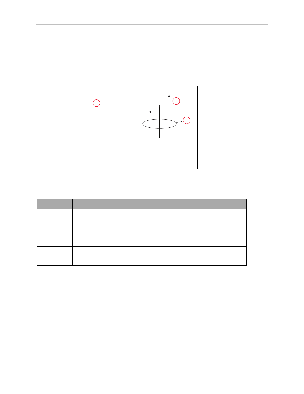
4.6 Connecting 200-240 VAC Power to Robot
EENNL
L
eCobra Robots
1Ø 200–240
VAC
1
2
3
In the industrial environment, nonperiodic overvoltage peaks may appear on mains power
supply lines as a result of power interruptions to high-energy equipment (such as a blown fuse
on one branch in a 3-phase system). This will cause high current pulses at relatively low
voltage levels. The user shall take the necessary steps to prevent damage to the robot system
(such as by interposing a transformer). See IEC 1131-4 for additional information.
AC Power Diagrams
Figure 4-10. Typical AC Power Installation with Single-Phase Supply
Table 4-12. Single-Phase Power Supply Description
Item Description
1 1 Ø, 200-240 VAC @ 20A
L = Line
N = Neutral
E = Earth Ground
2 User- supplied ACPower Cable
3 User- supplied fuse, slow blow, 10A
56 eCobra User's Guide 14402-000 Rev. F
Page 57

Chapter 4: System Installation
EENL3L
L1
L2
eCobra Robots
1Ø 200–240 VAC
1
2
4
3
3
5
Figure 4-11. Single-Phase Load across L1 and L2 of a Three-Phase Supply
Table 4-13. Three-phase Power Supply Description
Item Description
1 3 Ø, 200-240 VAC
2 200 -240 VAC
3 User-supplied fuses, slow blow, 10 A
4 User-supplied ACPower Cable
5 L = Line 1
N = Line 2
E = Earth Ground
NOTE: If a three-phase power source is used, it must be symmetrically-earthed
(with grounded neutral). Connections called out as single-phase can be wired
Line-to-Neutral or Line-to-Line.
14402-000 Rev. F eCobra User's Guide 57
Page 58

4.6 Connecting 200-240 VAC Power to Robot
AC Mating Connector
The AC mating connector is supplied with each system. It is shipped in the cable/accessories
box. The supplied plug is internally labeled for the AC power connections (L, E, N).
Table 4-14. AC Mating Connector Details
AC Connector details AC in-line power plug,
straight, female, screw terminal, 10 A, 250 VAC
Qualtek P/N 709-00/00
Digi-Key P/N Q217-ND
NOTE: The AC power cable is not supplied with the system.
Creating the 200-240 VAC Cable
1.
Locate the AC mating connector shown in the previous table.
2.
Open the connector by unscrewing the screw on the shell and removing the cover.
3.
Loosen the two screws on the cable clamp. See Figure 4-12.
4.
Use 18 AWG wire to create the AC power cable. Select the wire length to safely reach
from the user-supplied AC power source to the robot base.
5.
Strip approximately 18 to 24 mm insulation from each of the three wires.
6.
Insert the wires into the connector through the removable bushing.
7.
Connect each wire to the correct terminal screw, and tighten the screw firmly.
8.
Tighten the screws on the cable clamp.
9.
Reinstall the cover and tighten the screw to seal the connector.
10.
Prepare the opposite end of the cable for connection to the facility AC power source.
58 eCobra User's Guide 14402-000 Rev. F
Page 59

Chapter 4: System Installation
1
2
5
4
3
Figure 4-12. AC Power Mating Connector
Table 4-15. AC Power Mating Connector Description
Item Description
1 Earth
2 Neutral
3 Removable Bushing
4 Cable Clamp
5 Line
Connecting AC Power Cable
1.
Connect the unterminated end of the AC power cable to your facility AC power source.
See AC Power Diagrams on page 56. Do not turn on AC power at this time.
2.
Plug the AC connector into the AC power connector on the interface panel on the robot.
3.
Secure the AC connector with the locking latch.
4.7 Grounding the Robot System
Proper grounding is essential for safe and reliable robot operation. Follow these recommendations to properly ground your robot system.
Grounding the Robot Base
The user can install a ground wire at the robot base to ground the robot. See the following figure. The robot ships with an M8 x 12 stainless steel, hex-head screw, and M8 split and flat
14402-000 Rev. F eCobra User's Guide 59
Page 60

4.8 Configuring a PLC
1
2
washers installed in the grounding hole. The user is responsible for supplying the ground wire
to connect to earth ground.
Figure 4-13. (1) Ground Point on Robot Base and (2) Ground Label
NOTE: The resistance of the earth ground conductor must be ≤ 10 Ω.
Grounding Robot-Mounted Equipment
The following two parts of an eCobra robot are not grounded to protective earth: the Joint 3
quill and the tool flange. If hazardous voltages are present at any user-supplied robot-mounted
equipment or tooling, you must install a ground connection from that equipment or tooling to
the ground point on the robot base. Hazardous voltages can be considered anything in excess
of 30 VAC (42.4 VAC peak) or 60VDC.
Also, for the grounding point on the tool flange, see Figure 8-6.
WARNING: ELECTROCUTIONRISK
Failing to ground robot-mounted equipment or tooling that uses hazardous
voltages could lead to injury or death of a person touching the end-effector
when an electrical fault condition exists.
4.8 Configuring a PLC
A PLC is user-supplied. This section describes how to configure your PLC for automatic startup when the system boots.
1.
Start the ACE software.
2.
Open the Controller object.
3.
In the Configure tab, select Configure Controller, then click Finish.
60 eCobra User's Guide 14402-000 Rev. F
Page 61

4.
Select SYSTEM_SECTION >eplc_autostart.
Chapter 4: System Installation
5.
Click Edit (or double-click the selection).
6.
Check the eplc_autostart box. It defaults to unchecked.
14402-000 Rev. F eCobra User's Guide 61
Page 62

4.9 Installing User-Supplied Safety Equipment
7.
Save the configuration by clicking Accept and then Yes.
4.9 Installing User-Supplied Safety Equipment
The user is responsible for installing safety barriers to protect personnel from coming in contact with the robot unintentionally. Depending on the design of the workcell, safety gates, light
curtains, and emergency stop devices can be used to create a safe environment. Read the Robot
Safety Guide for a discussion of safety issues.
The user-supplied safety and power-control equipment connects to the system through the
XUSR and XFP connectors on the eAIB XSYSTEM cable. The XUSR connector (25-pin) and XFP
(15-pin) connector are both female D-sub connectors. Refer to the following table for the XUSR
pin-out descriptions. See "Contacts Provided by the XFP Connector" for the XFP pin-out descriptions. See the figure E-Stop Circuit on XUSR and XFP Connectors on page 66 for the XUSR wiring diagram.
62 eCobra User's Guide 14402-000 Rev. F
Page 63

Chapter 4: System Installation
Table 4-16. Contacts Provided by the XUSR Connector
Pin
Pairs
Description Comments
Voltage-Free Contacts Provided by Customer
1, 14 User E-Stop CH 1 (mushroom
N/C contacts, Shorted if NOT Used
push-button, safety gates, etc.)
2, 15 User E-Stop CH 2 (same as pins
N/C contacts, Shorted if NOT Used
1, 14)
3, 16 Line E-Stop (used for other robot or
N/C contacts, Shorted if NOT Used
assembly line E-Stop interconnection. Does not affect E-Stop
indication (pins 7, 20))
4, 17 Line E-Stop (same as pins 3, 16) N/C contacts, Shorted if NOT Used
5, 18 Muted safety gate CH 1 (causes E-
N/C contacts, Shorted if NOT Used
Stop in Automatic mode only)
6, 19 Muted Safety Gate CH 2 (same as
N/C contacts, Shorted if NOT Used
pins 5, 18)
Voltage-Free Contacts provided by eCobra
7, 20 E-Stop indication CH 1 Contacts are closed when Front Panel,
pendant, and customer E-Stops are not
tripped
8, 21 E-Stop indication CH 2 (same as
pins 7, 20)
Contacts are closed when Front Panel,
pendant, and customer E-Stops are not
tripped
9, 22 Manual/Automatic indication CH 1 Contacts are closed in Automatic mode
10, 23 Manual/Automatic indication CH 2 Contacts are closed in Automatic mode
11, 12,
No connection
13, 24,
25
14402-000 Rev. F eCobra User's Guide 63
Page 64

4.9 Installing User-Supplied Safety Equipment
Table 4-17. Contacts Provided by the XFP Connector
Pin
Pairs
Description Requirements for User-
Supplied Front Panel
Voltage-Free Contacts Provided by Customer
1, 9 Front Panel E-Stop CH 1 User must supply N/C con-
tacts
2, 10 Front Panel E-Stop CH 2 User must supply N/C con-
tacts
3, 11 Remote Manual/Automatic switch CH 1.
Manual = Open Automatic = Closed
4, 12 Remote Manual/Automatic switch CH 2.
Manual = Open Automatic = Closed
Optional - jumper closed for
Auto Mode-only operation
Optional - jumper closed for
Auto Mode-only operation
6, 14 Remote High Power on/off momentary push-button User must supply moment-
ary push-button to enable
High Power to system
Non-voltage-Free Contacts
5, 13 System-Supplied 5 VDC and GND for High Power
On/Off Switch Lamp
User must supply lamp, or
use 1 W, 47 ohm resistor system will not operate if
not present
a
7, 15
Controller system 5 V power on LED, 5 V, 20mA Optional - indicator only
8 No connection
See the figure Front Panel Schematic on page 68 for a schematic diagram of the Front Panel.
a
Users must exercise caution to avoid inadvertently connecting 24 V signals to these pins,
because this will damage the electronics.
NOTE: The system was evaluated by Underwriters Laboratory with a Front
Panel. Using a substitute front panel could void UL compliance.
64 eCobra User's Guide 14402-000 Rev. F
Page 65

Chapter 4: System Installation
Table 4-18. Remote Pendant Connections on the XMCP Connector
Pin XMCP
(15-Pin D-Sub)
Description
1, 9 Pendant E-Stop Push-button CH 1
2, 10 Pendant E-Stop Push-button CH 2
3, 11 Pendant Enable CH 1 (Hold-to-run)
4, 12 Pendant Enable CH 2 (Hold-to-run)
13 Serial GND/Logic GND
7 Pendant TXD: “eV+to Pendant TXD”
8 Pendant RXD: “eV+to Pendant RXD”
14 No connection
15 No connection
Shield Shield GND
6 24 V
5 No connection
The following figure shows an E-Stop diagram for the system. See Emergency Stop Circuits on
page 68 for a description of the functionality of this circuit.
14402-000 Rev. F eCobra User's Guide 65
Page 66

4.9 Installing User-Supplied Safety Equipment
ES1
ES2
XSYSTEM-31
(XFP-1)
XSYSTEM-20
(XFP-9)
(XPND-7)
XSYSTEM-24
(XPND-24)
(XUSR-1)
(XUSR-14)
XSYSTEM-13
(XUSR-3)
(XPND-9)
XSYSTEM-8
(XPND-26)
XSYSTEM-32
(XFP-2)
(XFP-10)
(XPND-6)
(XPND-23)
(XUSR-2)
(XUSR-15)
XSYSTEM-43
(XUSR-4)
XSYSTEM-39 (XUSR-17)
XSYSTEM-9 (XUSR-16)
(XPND-8)
XSYSTEM-38
(XPND-25)
XSYSTEM-29 (XUSR-18)
XSYSTEM-44 (XUSR-19)
ES1
ES2
SR1 SR2
AM2 AM1
XSYSTEM-14
(XUSR-5)
XSYSTEM-30
(XUSR-6)
XSYSTEM-33 (XFP-13)
XSYSTEM-3 (XFP-5)
XSYSTEM-31 (XFP-6)
XSYSTEM-34 (XFP-14)
XSYSTEM-5
(XFP-4)(XFP-3)
XSYSTEM-19
(XFP-12)
XSYSTEM-4
(XFP-11)
AM2
Coil
AM1
Coil
XSYSTEM-12 (XUSR-9)
XSYSTEM-28 (XUSR-10)
AM2
AM1
XSYSTEM-42 (XUSR-23)
XSYSTEM-27 (XUSR-22)
XSYSTEM-26 (XUSR-8)
XSYSTEM-10 (XUSR-7)
XSYSTEM-25 (XUSR-20)
XSYSTEM-40 (XUSR-21)
1
2
17
16
15
14
13
12
11
10
9
8
7
6
5
4
3
18
Figure 4-14. E-Stop Circuit on XUSR and XFP Connectors
66 eCobra User's Guide 14402-000 Rev. F
Page 67

Chapter 4: System Installation
Table 4-19. E-Stop Circuit on XUSR and XFPConnectors Description
Item Description
1 ESTOP 24 VSource
2 ESTOPGround
3 Front Panel ESTOPPushbutton
4 T20 ESTOPPushbutton
5 User E-Stop and Gate Interlock (jumper closed when not used, must open both chan-
nels independently if used)
6 LINEE-Stop (external user E-Stop system)
7 T20 Pendant Enable
8 Muted Safety Gate - Active in auto mode only (jumper closed when not used)
9 Manual Mode Path
10 Auto Mode Path
11 Force-Guided Relay Cyclic Check Control Circuit
12 Single-Phase AC Input, 200-240 VAC
13 High Power to Amplifiers (internal connections)
14 Front Panel High Power ON / OFF (6 V, 1.2 W bulb)
15 ESTOP24VSource
16 Front Panel Auto / Manuals Keyswitch
17 Auto / Manual Output
18 User ESTOP Output
14402-000 Rev. F eCobra User's Guide 67
Page 68

4.9 Installing User-Supplied Safety Equipment
ESTOPSRC
24 VS
5 VD
D
SYSPWRLT 7
6
5
4
2
3
1
17
16
8
10
9
11
12
13
14
15
XFP
15PDSUBM
MANUALSRC1
HIPWRREQ
MANUALRLY2
MANUALRLY1
HIPWRLT
ESTOPFP2
ESTOPFP1
HPLT5V
NC
MANUALSRC2
MANUALSRC1
SW1
MANUALRLY2
MANUALRLY1
MANUALSRC2
24 VS
SWL1
HIPWRREQ
HPLT5 V
HIPWRLT
D
ESTOPSRC
SW2
ESTOPFP2
ESTOPFP1
5 VD
D
2-PIN_MINI
SYSPWRLT
1
2 4
3
Figure 4-15. Front Panel Schematic
Table 4-20. Front Panel Schematic Description
Item Description
1 System Power LED
2 Manual / Auto
3 High Power ON / OFF
4 Emergency Stop
Emergency Stop Circuits
The eAIB XSYSTEM cable provides connections for Emergency Stop (E-Stop) circuits on the
XUSR and XFP connectors. This gives the controller system the ability to duplicate E-Stop functionality from a remote location using voltage-free contacts. See Figure 4-14.
The XUSR connector provides external two-channel E-Stop input on pin pairs 1, 14 and 2, 15.
The XFP connector provides two-channel E-Stop input on pin pairs 1, 9 and 2, 10.
NOTE: These pin pairs must be shorted if not used. Both channels must open
independently if used. The controller will flag an error state if one channel is
jumpered closed and the other channel is opened, although an Emergency Stop
will still occur. It will also flag an error state if the independent channels are
crossed, meaning one line from each channel is accidentally connected to the
other channel.
68 eCobra User's Guide 14402-000 Rev. F
Page 69

Chapter 4: System Installation
User E-Stop Indication Contacts - Remote Sensing of E-Stop
These contacts provide a method to indicate the status of the ESTOP chain, inclusive of the
Front Panel Emergency Stop push-button, the pendant Emergency Stop push-button, and the
User Emergency Stop Contacts.
NOTE: These contacts do not indicate the status of any connections below the
User E-Stop contacts. Thus, they will NOT indicate the status of the Line E-Stop,
MCP ENABLE, or the Muted Safety gate. If you have a specific need in this area,
contact your local Omron support for information on alternate indicating modes.
Two pairs of pins on the XUSR connector (pins 7, 20 and 8, 21) provide voltage-free contacts,
one for each channel, to indicate whether the E-Stop chain, as described above, on that channel
is closed. Both switches are closed on each of the redundant circuits in normal operation (no
E-Stop). The user may use these contacts to generate an E-Stop for other equipment in the workcell. The load on the contacts must not exceed 40 VDC or 30VAC at a maximum of 1 A.
These voltage-free contacts are provided by a redundant, cyclically-checked, positive-drive,
safety relay circuit for Category 3 PL-d per ISO 13849 operation (see Figure 4-14. and the table
Contacts Provided by the XFP Connector on page 64 for the customer E-Stop circuitry).
Line E-Stop Input
The XUSR connector on the controller contains a two-channel Line E-Stop input for workcell,
production line, or other equipment emergency-stop inputs. Generally, the customer E-Stop
Indication contact outputs are used to generate an emergency stop in such external equipment.
Thus, if one were to wire the same equipment’s outputs into the customer E-Stop input (that is,
in series with the local robot’s E-Stop push-buttons), a lock-up situation could occur.
The Line E-Stop input comes into the circuit at a point where it cannot affect the customer EStop indication relays and will not cause such a lock-up situation. For any situation where two
systems should be cross-coupled, for example, the customer E-Stop indication of one controller
is to be connected to the input of another controller, the Line E-Stop input is the point to bring
in the other controller’s output contacts. See the figure E-Stop Circuit on XUSR and XFP Connectors on page 66 for more information.
Do not use the Line E-Stop for such devices as local E-Stop push-buttons, since their status
should be reported to the outside on the local user E-Stop indication output contact while the
Line E-Stop inputs will not.
Muted Safety Gate E-Stop Circuitry
Two pairs of pins on the XUSR connector (pins 5, 18 and 6, 19) provide connections for a
safety gate designed to yield an E-Stop allowing access to the workspace of the robot in
Manual mode only, not in Automatic mode. It is up to the customer to determine if teaching
the robot in Manual Mode, by a skilled programmer (See Qualification of Personnel in the
Robot Safety Guide), wearing safety equipment and carrying a pendant, is allowable under local
regulations. The E-Stop is said to be “muted” in Manual mode (for the customer E-Stop circuitry, see the figures and tables at the beginning of this section).
The muted capability is useful for a situation where a shutdown must occur if the cell gate is
opened in Automatic mode, but you need to open the gate in Manual mode. If the mute gate is
opened in Automatic mode, the robot defaults to Manual mode operation when power is reenabled. In muted mode, the gate can be left open for personnel to work in the robot cell.
However, safety is maintained because of the speed restriction.
14402-000 Rev. F eCobra User's Guide 69
Page 70

4.9 Installing User-Supplied Safety Equipment
!
!
!
WARNING: PERSONALINJURYRISK
If you want the cell gate to always cause a robot shutdown, wire the gate
switch contacts in series with the user E-Stop inputs. Do not wire the gate
switch into the muted safety gate inputs.
Remote Manual Mode
The Front Panel provides for a Manual Mode circuit. See Remote High Power On/Off Control
on page 71 for further details about the customer Remote Manual Mode circuitry.
The Front Panel, or the user-supplied panel, must be incorporated into the robot workcell to
provide a “Single Point of Control” (the pendant) when the controller is placed in Manual
mode. Certain workcell devices, such as PLCs or conveyors, may need to be turned off when
the operating mode switch is set to Manual mode. This is to ensure that the robot controller
does not receive commands from devices other than from the pendant, the single point of control.
If the user needs to control the Manual/Automatic mode selection from other control equipment, then a custom splitter cable or complete replacement of the Front Panel may be required.
See Front Panel Schematic on page 68. In this situation, a pair of contacts should be wired in
series with the Front Panel Manual/Automatic mode contacts. Thus, both the Front Panel and
the customer contacts need to be closed to allow Automatic mode.
WARNING: PERSONALINJURYRISK
Do not wire user-supplied Manual/Automatic contacts in parallel with the
Front Panel switch contact. This would violate the “Single Point of Control”
principle and might allow Automatic (high-speed) mode to be selected while
an operator is in the cell.
User Manual/Auto Indication
Two pairs of pins on the XUSR connector (pins 9, 22 and 10, 23) provide a voltage-free
contact to indicate whether the Front Panel and/or remote Manual/Automatic switches are
closed. The user may use these contacts to control other mechanisms (for example, conveyor,
linear modules, etc.) when Manual mode is selected. The load on the contacts should not
exceed 40 VDC or 30 VAC at a maximum of 1 A.
WARNING: PERSONALINJURYRISK
Return any suspended safeguards to full functionality prior to selecting Automatic Mode.
User High Power On Indication
In the optional SmartController EX, eV+ controls a normally-open relay contact on the XDIO
connector (pins 45, 46, see the table XDIO Digital I/O Connector Pin Assignments in the
SmartController EX manual), that will close when high power has been enabled. The user can
use this feature to power an indicator lamp or other device, that signals High Power is On.
The limit on these contacts is 1 A at 30 VDC or 30 VAC.
70 eCobra User's Guide 14402-000 Rev. F
Page 71

Chapter 4: System Installation
!
Remote High Power On/Off Control
The easiest and most effective way to provide the high power on/off control in a remote location is to mount the Front Panel in the desired location with an extension cable.
However, if the user needs to control high power on/off from other control equipment or from
a location other than the Front Panel, then a custom splitter cable will be required. See the
Front Panel schematic (Front Panel Schematic on page 68) for details of the Front Panel’s wiring. In this situation, a second momentary contact for high power on/off would be placed in
parallel with the Front Panel push-button contact. This second contact should be suppressed
when in Manual mode (see the note on “Single Point of Control” below).
This method allows relocating the push-button switch to a more convenient location. Implementation of this method must conform to EN standard recommendations.
NOTE: European standards require that the remote High Power push-button be
located outside of the workspace of the robot.
Pins 6, 14 and 5, 13 of the XFP connector provide this remote capability. Pins 5, 13 provide
power for the lamp, +5 VDC and ground, respectively. Pins 6, 14 are inputs for voltage-free normally-open contacts from a user-supplied momentary push-button switch.
WARNING: PERSONALINJURYRISK
To fulfill the “Single Point of Control” requirement, do not place the Manual/Automatic and High Power On controls in multiple locations. After putting
the robot into Manual mode, the operator should remove the key for safety purposes. The system should not be wired so that a PLC or another operator can
put the system back into Automatic mode.
High Power On/Off Lamp
The Front Panel High Power On/Off Lamp (p/n: 27400-29006) will cause an error, from eV+, if
the lamp burns out. This error prevents High Power from being turned on. This safety feature
prevents a user from not realizing that High Power is enabled because the High Power indicator is burned out. See Changing the Lamp In the Front Panel High-Power Indicator on page
119 for information on changing this lamp.
Remote Front Panel or User-Supplied Control Panel Usage
Users can mount the Front Panel remotely by using an extension cable or by wiring a user-supplied Front Panel (control panel) to the controller using the 15-pin XFP connector. The Front
Panel contains no active components, only switches and lights. Customers should be able to
adapt the Front Panel’s functionality into their own Front Panel design. To automatically control the Front Panel’s signals, use relay contacts instead of switches. See the figure Front Panel
Schematic on page 68 for a schematic drawing of the Front Panel, and see the table System
Installation on page 35 for a summary of connections and pin numbers.
NOTE: The system was evaluated by Underwriters Laboratory with our Front
Panel. If you provide a substitute front panel, the system may no longer be UL
compliant.
14402-000 Rev. F eCobra User's Guide 71
Page 72

4.9 Installing User-Supplied Safety Equipment
Customers can build an extension cable to place the Front Panel in a remote location. The
extension cable must conform to the following specifications:
l
Wire Size: must be larger than 26 AWG.
l
Connectors: must be 15-pin, standard D-sub male and female.
l
Maximum cable length is 10 meters.
NOTE: The XMCP and XFP connectors can be interchanged without electrical
damage. However, neither the Front Panel nor the pendant will work properly
unless they are plugged into the correct connector.
Remote Pendant Usage
Customers can build an extension cable to place the pendant in a remote location. The extension cable must conform to the following specifications:
l
Wire Size: must be larger than 26 AWG.
l
Connectors: must be 15-pin, standard D-sub male and female.
l
Maximum cable length is 10 meters.
IMPORTANT: Do not modify the cable that is attached to the pendant. This
could cause unpredictable behavior from the robot system.
72 eCobra User's Guide 14402-000 Rev. F
Page 73

Chapter 5: System Operation
1
5.1 Robot Status LED Description
The robot Status LED indicator is located on the top of the upright robots, and at the top of the
status panel for the eCobra Inverted robot. The blinking pattern indicates the status of the
robot.
The eCobra robots support the UL standard. The LED on these robots is amber. See the following figure and table.
Figure 5-1. (1) Robot Status LED Indicator Location, Upright Model Shown
Table 5-1. Status LED Definitions on UL-Certified Robots
LED Status 2-Digit Status Panel Display Description
Off Off 24 VDC not present
Off OK High Power Disabled
Amber, Solid ON High Power Enabled
Amber, Slow Blink OK Selected Configuration Node
Amber, Fast Blink Fault Code(s) Fault, see the next section
Amber, Solid Fault Code(s) Fault, see the next section
5.2 Status Panel Fault Codes
The status panel, shown in the following figure, displays alpha-numeric codes that indicate
the operating status of the robot, including fault codes. The following table gives meanings of
the fault codes, which provide information for isolating problems during troubleshooting.
14402-000 Rev. F eCobra User's Guide 73
Page 74

5.2 Status Panel Fault Codes
1
2
The displayed fault code will continue to be displayed even after the fault is corrected or additional faults are recorded. All displayed faults will be cleared from the display, and reset to a
no-fault condition, upon successfully enabling high power to the robot, or power cycling the 24
V supply to the robot.
Figure 5-2. (1) Status Panel for Displaying Fault Codes, (2) ZBrake Release Button - Upright Model
Shown.
Status Panel
The status panel, shown in Figure 5-2. displays alpha-numeric codes that indicate the operating status of the robot. The following table gives definitions of the fault codes. These codes
provide details for quickly isolating problems during troubleshooting.
In the Status Panel Codes table, the '#' in the LED column represents a single digit. The digits
will be displayed as one of the following:
0 1 2 3 4 5 6 7 8 9
Table 5-2. Status Panel Codes
LED
Status
Code
OK None N/A STATUS message-High
V+
Error
Message
V+
Error
Code
Explanation User Action
None
Power OFF.
ON None N/A STATUS message-High
Power ON.
MA None N/A STATUS message-Robot
24 *RSC power fail-
ure*
is in Manual Mode.
-670 The 24 VDC input
voltage is out of bounds
None
None
Check connections
and voltage level
74 eCobra User's Guide 14402-000 Rev. F
Page 75

Chapter 5: System Operation
#
#
#
#
LED
Status
Code
A# *Motor Amplifier
Fault*
AC *RSC Power Fail-
ure*
V+
Error
Message
V+
Error
Code
-1018 A power amplifier fault is
-670 A loss of AC power was
Explanation User Action
(too high or low). from the user-sup-
indicated on axis #.
detected.
plied 24 VDC power
supply.
Check user motor
power connections
for shorts or opens.
Turn high power
back on and restart
the program. If the
error persists, contact your local
Omron support.
Check user AC power
connections for
shorts or opens.
Turn high power
back on and restart
the program. If the
error persists, contact your local
Omron support.
B# None N/A IO-Blox communications
error with IO-Blox (#).
BA None N/A The encoder backup bat-
tery is low.
D# *Duty-cycle
exceeded*
Mtr #
-1021 The indicated motor (#)
has been driven hard for
too long a period of time.
The servo system has disabled power to protect
the robot hardware.
Check user IOBlox
connections for
shorts or opens.
Check IOBlox
address switches for
proper configuration.
Cycle power to the
control system. If
the error persists,
contact your local
Omron support.
Replace the encoder
backup battery.
Turn high power
back on; reduce the
speed and/or acceleration for the
motion that was in
progress or for
motions that preceded that motion.
Repeat the motion
that failed.
E# *Encoder Fault* -1025 The servo system has User actions vary by
14402-000 Rev. F eCobra User's Guide 75
Page 76

5.2 Status Panel Fault Codes
#
#
LED
Status
Code
ES *E-STOP detected
by robot*
F1 *E-STOP detected
by robot*
FM None N/A Firmware version mis-
FW *1394 com-
munications
timeout*
V+
Error
Message
V+
Error
Code
-643 An E-STOP condition has
-643 The End-Of-Arm Break-
-927 The IEEE 1394 com-
Explanation User Action
detected an encoder
fault.
been detected by the
robot.
away Sensor has tripped
(open circuit). Reporting
of this error can be
enabled / disabled via
ACE.
match.
munications system has
failed to initialize or has
lost communications
with the SmartController EX.
product. Please reference individual
robot manuals for
appropriate actions.
This is a normal
response to many ESTOP conditions.
Remove the source
of the ESTOP and reenable high power.
Re-close the breakaway circuit and reenable high power.
Contact your local
Omron support.
This will occur normally if the
SmartController EX
is powered down separately from the
robot systems. If it
occurs unexpectedly, check the
connections and
integrity of the 1394
cabling.
h# *Robot over-
heated*
H# *Motor over-
heating* Mtr #
-606 The temperature sensor
on the embedded processor board has
reached its temperature
limit. It may be necessary to slow the motion
or insert pauses to
reduce overall heating.
-1016 The motor encoder temperature sensor indicates an
overtemperature.
Check for excessive
ambient temperature, inadequate ventilation,
and proper function
of any cooling fans.
Reduce the speed,
acceleration and/or
deceleration of the
robot motions, or
introduce delays in
the application cycle
to give the motor an
opportunity to cool.
76 eCobra User's Guide 14402-000 Rev. F
Page 77

Chapter 5: System Operation
#
#
LED
Status
Code
hV *RSC power fail-
ure*
I# None N/A Servo initialization
M# *Motor stalled*
Mtr #
V+
Error
Message
V+
Error
Code
-670 The high-voltage DC bus
-1007 A motor stall occurs
Explanation User Action
for the amplifiers is out
of bounds (too high or
low).
stages. These steps normally sequence (I0, I1,
…) on the display during
normal system boot.
when the maximum
allowed torque for a
given motor was applied
for longer than the
defined timeout period.
This typically occurs
when an obstacle is
encountered.
This may occur
when AC power is
unexpectedly
removed. Check AC
connections and reenable high power. If
the error persists,
contact your local
Omron support.
None, unless an initialization code persists longer than 30
seconds. This may
indicate servo initialization has failed.
Contact your local
Omron support.
Check for obstacles
and free movement
of all joints. Turn
high power back on
and repeat the
motion that failed.
P0 *Power system
failure* Code 0
P1 *Power system
failure* Code 1
P2 *Power system
failure* Code 2
P3 *Power system -1115 The regenerative energy Contact your local
-1115 The dual-channel brake
circuit has reported a cyclic check error.
-1115 The power system has
unexpectedly turned off
power.
-1115 The high-voltage DC bus
to the regenerative
energy dump circuit has
experienced an overvoltage.
Contact your local
Omron support.
On PA-4 chassis, further information
may be indicated on
the PA-4 status
lights. Refer to Adept
PA-4 Power Chassis
User's Guide for
details. Contact your
local Omron support
if the error persists.
Contact your local
Omron support.
14402-000 Rev. F eCobra User's Guide 77
Page 78

5.2 Status Panel Fault Codes
LED
Status
Code
failure* Code 3 dump circuit has
P4 *Power system
failure* Code 4
P5 *Power system
failure* Code 5
PR None N/A A servo task has overrun
V+
Error
Message
V+
Error
Code
-1115 The high-voltage DC bus
-1115 An inrush error was
Explanation User Action
exceeded its max shortterm dump rating.
did not discharge its
voltage when expected.
(Note: This error is only
relevant to legacy Cobra
AIB systems.)
detected by the power
sequencer. This means
the high-voltage DC bus
failed to rise at the expected rate when power
was enabled.
its allotted execution window.
Omron support.
Contact your local
Omron support.
This can occur if AC
power is abruptly
removed during the
high-power enable
sequence. If it
occurs unexpectedly, contact
your local Omron
support.
If the problem persists, contact your
local Omron support.
RC *RSC com-
munications failure*
S0 *Safety System
Fault* Code 0
S1 *Safety System
Fault* Code 1
S2 *Safety System
Fault* Code 2
-651 There is a failure to communicate with the Robot
Signature Card.
-1109* The robot hardware did
not detect that the
front-panel high-power
button was pressed prior
to the servo system
attempting to enable
power.
-1109* The SmartController EX
has signaled a power off
condition to the robot via
the HIPWR_DIS line on
the XSYS interface. This
fault indication typically
accompanies other fault
conditions that cause
"fatal error" on the
SmartController EX error
(such as a loss in IEEE1394 communication).
-1109* The safety system exper- If the problem per-
Contact your local
Omron support.
Contact your local
Omron support.
Check for other messages on the
SmartController EX
that may indicate a
fatal error. If the
error source can be
eliminated, reenable power.
sists, contact your
78 eCobra User's Guide 14402-000 Rev. F
Page 79

Chapter 5: System Operation
LED
Status
Code
S3 *Safety System
Fault* Code 3
S4 *Safety System
Fault* Code 4
V+
Error
Message
V+
Error
Code
-1109* The safety system exper-
-1109* The internal E-STOP
Explanation User Action
ienced a failure on channel 1 during the cyclic
check of dual-channel
power system. This may
indicate a welded relay
contact or other hardware failure.
ienced a failure on channel 2 during the cyclic
check of dual-channel
power system. This may
indicate a welded relay
contact or other hardware failure.
delay timer timed out
and power has been
turned off. Under normal
circumstances, software
sequences the shutdown prior to the timeout, averting this message.
local Omron support.
If the problem persists, contact your
local Omron support.
If the problem persists, contact your
local Omron support.
S5 *Safety System
Fault* Code 5
S6 *Safety System
Fault* Code 6
S9 *Safety System
Fault* Code 9
SE *Safety System -648 The E-Stop Delay has Commission and
-1109* The power system was
not properly unlocked by
software during a power
sequence while in
manual mode.
-1109* The CAT-3 hardware
safety system detected
an encoder OVERSPEED
and power has been
turned off. This circuitry
is active in manual mode
only, on select robots
which have the CAT-3
teach mode option
installed.
-1109* A watchdog circuit that
cross-checks the clocks
for the dual-channel
safety system is reporting an error.
Contact your local
Omron support.
This fault is triggered
on purpose during
specific commissioning tests for
the CAT-3 system. If
the fault occurs during normal operation, contact your
local Omron support.
Contact your local
Omron support.
14402-000 Rev. F eCobra User's Guide 79
Page 80

5.3 Brakes
#
LED
Status
Code
Not
Commissioned*
SW None N/A Software watchdog
T0 *Safety System
Fault* Code 10
TR *Safety System
Not
Commissioned*
V# *Hard envelope
error* Mtr #
V+
Error
Message
V+
Error
Code
-1109 An error was detected
-648 The Teach Restrict fea-
-1027 The indicated motor was
Explanation User Action
not been commissioned
and verified.
timer timeout. On some
products it is normal for
this to occur momentarily during a servo
reset.
during a software self
test of a secondary
safety and monitoring circuit (SRV_DIRECT /
SRV_STAT).
ture has not been commissioned and verified.
not tracking the commanded position with
sufficient accuracy as set
by ACE.
verify the E-Stop
Delay.
If the problem persists, contact your
local Omron support.
Contact your local
Omron support.
Commission and
verify the Teach
Restrict feature.
Turn on high power
and try to perform
the motion at a
slower speed. Make
sure that nothing is
obstructing the
robot's motion. If
the error recurs, contact your local
Omron support.
NOTE: For more information on status codes, refer to the Status Codes for
Embedded Products document.
5.3 Brakes
The robot has a braking system that decelerates the robot in an emergency or abnormal situation, such as when the emergency stop circuit is open or a robot joint passes its softstop.
The braking system will not prevent you from moving the robot manually once the robot has
stopped (and high power has been removed).
In addition, Joint 3 has an electromechanical brake. The brake is released when high power is
enabled. When high power is turned off, the brake engages and holds the position of Joint 3.
Brake Release Button
Under some circumstances you may want to manually position Joint 3 on the Z-Axis without
turning on high power. For such instances, a ‘Z’ Brake Release button is located above the
80 eCobra User's Guide 14402-000 Rev. F
Page 81

Chapter 5: System Operation
!
1
2
5
4
3
robot status panel, as shown in Figure 5-2. When system power is on, pressing this button
releases the brake, which allows movement of Joint 3.
NOTE: 24 Volt robot power must be on to release the brake.
If this button is pressed while high power is on, high power will automatically shut off.
CAUTION: PROPERTYDAMAGERISK
Pressing the Brake Release button may cause the quill and tool flange to fall.
When the Brake Release button is pressed, Joint 3 may drop to the bottom of its
travel. To prevent possible damage to the equipment, make sure that Joint 3 is
supported while releasing the brake and verify that the end-effector or other
installed tooling is clear of all obstructions.
Remote Brake Release Feature
You can also configure the XIO Input 6.2 (pin 18) to act as an alternate hardware brake release
input. The setting is available on the Robot page in the ACE software. The parameter is
Remote Brake Release Input. When enabled (True), activating XIO Input 6.2 is identical to
pressing the brake button on the status display. The input status will still reflect in the IO
register.
If an alternate (user-supplied)brake release button is used, ensure that the brake release button
displays a warning similar to the preceding WARNING. This is to comply with ISO 10218-1,
Clause 5.13.
5.4 Front Panel
NOTE: The factory-supplied Front Panel E-Stop is designed in accordance with
the requirements of IEC 60204-1 and ISO 13849.
IMPORTANT: Any user-supplied front panel E-Stop must be designed in accordance with the requirements of IEC 60204-1 and ISO 13849. The push button of
the E-Stop must comply with ISO 13850 (Clause 5.5.2).
14402-000 Rev. F eCobra User's Guide 81
Figure 5-3. Front Panel
Page 82

5.4 Front Panel
!
!
1.
XFP connector
Connects to the XFP connector on the eAIB XSYSTEM cable (or the optional SmartController EX, if one is being used).
2.
System 5 V Power-On LED
Indicates whether or not power is connected to the robot.
3.
Manual / Automatic Mode Switch
Switches between Manual ( ) and Automatic ( ) mode. In Automatic mode,
executing programs control the robot, and the robot can run at full speed. In Manual
mode, the system limits robot speed and torque so that an operator can safely work in
the cell. Manual mode initiates hardware and software restrictions on robot speed, commanding no more than 250 mm/sec.
There is no high speed mode in manual mode.
WARNING: PERSONALINJURYRISK
If an operator is going to be in the work cell in manual mode, it is
strongly recommended that the operator carry an enabling device. The
Enable button on the manual control pendant is such a device.
WARNING: PERSONALINJURYRISK
Whenever possible, manual mode operations should be performed with
all personnel outside the workspace.
4.
High Power On / Off Switch and Lamp
Controls high power, which is the flow of current to the robot motors. Enabling high
power is a two-step process. An “Enable Power” request must be sent from the user-supplied PC, an executing program, or a pendant. Once this request has been made and the
High Power On/Off lamp/button is blinking, the operator must press and release this
button, and high power will be enabled.
NOTE: The use of the blinking High Power button can be configured (or
eliminated) in software. Your system may not require this step.
IMPORTANT: Disabling the High Power button violates IEC 60204-1. It
is strongly recommended that you not alter the use of the High Power button.
NOTE: If enabled, the Front Panel button must be pressed while blinking
(default time-out is 10 seconds). If the button stops blinking, you must
enable power again.
5.
Emergency Stop Switch
The E-Stop is a dual-channel, passive E-Stop that supports Category 3 CE safety requirements. Pressing this button turns off high power to the robot motors.
NOTE: The Front Panel must be installed to be able to Enable Power to the
robot. To operate without a Front Panel, the user must supply the equivalent circuits.
82 eCobra User's Guide 14402-000 Rev. F
Page 83

5.5 Connecting Digital I/O to the System
You can connect digital I/O to the system in several different ways. See the following table and
figure.
NOTE: A typical IOBlox configuration is shown in Figure 5-4. Other configurations may be possible. Contact your local Omron support for more information.
Table 5-3. Digital I/O Connection Options
Product I/O Capacity For more details
Chapter 5: System Operation
XIO Connector on robot 12 inputs
8 outputs
Optional IO Blox Device,
connects to robot
8 inputs, 8 outputs per device;
up to eight IO Blox devices per
see eAIB XIO Connector Signals on page 86
see IO Blox User’s Guide. Not
available with eCobra Lite.
robot
The following I/Oconnector and module require the optional SmartController EX motion controller
XDIO Connector on
SmartController EX
12 inputs
8 outputs
SmartController EX User's
Guide
Optional I/O Products
These optional products are also available for use with digital I/O:
l
XIO Breakout Cable For information, see XIO Breakout Cable on page 93. This cable is
not compatible with the XIO Termination Block.
l
XIO Termination Block, with terminals for user wiring, plus input and output status
LEDs. Connects to the XIO connector with 6 foot cable. See the XIO Termination Block
Installation Guide for details.
14402-000 Rev. F eCobra User's Guide 83
Page 84

5.5 Connecting Digital I/O to the System
DC
IN
24V
GND
AC
200 240V
Ø
1
XBELTIO
XIO
Servo
ENETENET
XSYSTEM
SmartController EX
eCobra Robot
1
2
10
9
8
7
6
5
4
3
Default Digital I/O Signal Configuration
Figure 5-4. Connecting Digital I/O to the System
Table 5-4. Default Digital I/O Signal Configuration, Single Robot, no SmartController EX
Item Location Type Signal Range
2
Robot 1 XIO connector
On eAIB panel.
3
IO Blox 1 Inputs 1033–1040
a
Inputs 1001–1012
Outputs 0001–0008
Outputs 0033–0040
4
5
IO Blox 2 Inputs 1041–1048
Outputs 0041–0048
IO Blox 3 Inputs 1049–1056
Outputs 0049–0056
6
IO Blox 4 Inputs 1057–1064
Outputs 0057–0064
7
IO Blox 5 Inputs 1065–1072
Outputs 0065–0072
84 eCobra User's Guide 14402-000 Rev. F
Page 85

Chapter 5: System Operation
Item Location Type Signal Range
8
IO Blox 6 Inputs 1073–1080
Outputs 0073–0080
9
IO Blox 7 Inputs 1081–1088
Outputs 0081–0088
10
IO Blox 8 Inputs 1089–1096
Outputs 0089–0096
a
For Multi-Robot systems, see Single and Multiple Robot Configuration Guide.
Table 5-5. Default Digital I/O Signal Configuration, Single Robot, with SmartController EX
Item Location Type Signal Range
1
SmartController EX (optional)
XDIO connector
2
Robot 1 XIO connector
a
On eAIB panel.
3
IO Blox 1 Inputs 1113–1120
Inputs 1001–1012
Outputs 0001–0008
Inputs 1097–1108
Outputs 0097–0104
Outputs 0105–0112
4
IO Blox 2 Inputs 1121–1128
Outputs 0113–0120
5
IO Blox 3 Inputs 1129–1136
Outputs 0121–0128
6
IO Blox 4 Inputs 1137–1144
Outputs 0129–0136
NOTE: The signal number sequence at this point jumps ahead it is not contiguous from IO Blox 4 to IO Blox 5.
7
IO Blox 5 Inputs 1289–1296
Outputs 0257–0264
8
IO Blox 6 Inputs 1297–1304
Outputs 0265–0272
9
IO Blox 7 Inputs 1305–1312
Outputs 0273–0280
14402-000 Rev. F eCobra User's Guide 85
Page 86

5.5 Connecting Digital I/O to the System
Item Location Type Signal Range
10
IO Blox 8 Inputs 1313–1320
Outputs 0281–0288
a
For Multi-Robot systems, see Single and Multiple Robot Configuration Guide.
eAIB XIO Connector Signals
The XIO connector on the robot interface panel offers access to digital I/O, 12 inputs and 8 outputs. These signals can be used by eV+ to perform various functions in the workcell. See the
following table for the XIO signal designations.
l
12 Inputs, signals 1097 to 1108
l
8 Outputs, signals 0097 to 0104
Table 5-6. XIO Signal Designations
Pin No. Designation
Signal
Bank
eV+ Signal
Number
1 GND
2 24 VDC
3 Common 1 1
4 Input 1.1 1 1097
5 Input 2.1 1 1098
6 Input 3.1 1 1099
7 Input 4.1 1 1100
8 Input 5.1 1 1101
9 Input 6.1 1 1102
10 GND
11 24 VDC
12 Common 2 2
13 Input 1.2 2 1103
14 Input 2.2 2 1104
15 Input 3.2 2 1105
16 Input 4.2 2 1106
17 Input 5.2 2 1107
18 Input 6.2 2 1108
19 Output 1 0097
86 eCobra User's Guide 14402-000 Rev. F
Page 87

Chapter 5: System Operation
Pin 1Pin 9
Pin 10
Pin 18
Pin 26 Pin 19
Pin No. Designation
Signal
Bank
eV+ Signal
Number
20 Output 2 0098
21 Output 3 0099
22 Output 4 0100
23 Output 5 0101
24 Output 6 0102
25 Output 7 0103
26 Output 8 0104
XIO Input Signals
The 12 input channels are arranged in two banks of six. Each bank is electrically isolated from
the other bank and is optically isolated from the robot’s ground. The six inputs within each
bank share a common source/sink line.
The inputs are accessed through direct connection to the XIO connector (see the previous
table), or through the optional XIO Termination Block. See the documentation supplied with
the termination block for details.
For REACTI programming, high-speed interrupts, or vision triggers:
l
With a SmartController EX, you can only use the EXXDIO inputs.
l
Without a SmartController EX, you can only use the XIO inputs.
See the eV+ Language User’s Guide for information on digital I/O programming.
14402-000 Rev. F eCobra User's Guide 87
Page 88

5.5 Connecting Digital I/O to the System
XIO Input Specifications
Table 5-7. XIO Input Specifications
Operational voltage range 0 to 30 VDC
OFF state voltage range 0 to 3 VDC
ON state voltage range 10 to 30 VDC
Typical threshold voltage Vin= 8 VDC
Operational current range 0 to 7.5 mA
OFF state current range 0 to 0.5 mA
ON state current range 2.5 to 7.5 mA
Typical threshold current 2.0 mA
Impedance (Vin/I
Current at Vin= +24 VDC I
Turn on response time (hardware)
Software scan rate/response time
) 3.9 K Ω minimum
in
≤ 6 mA
in
5 µsec maximum
16 ms scan cycle/
32 ms max response time
Turn off response time (hardware)
Software scan rate/response time
5 µsec maximum
16 ms scan cycle/
32 ms max response time
NOTE: The input current specifications are provided for reference. Voltage
sources are typically used to drive the inputs.
88 eCobra User's Guide 14402-000 Rev. F
Page 89

Typical Input Wiring Example
1097
4
1098
5
1099
6
1100
7
1101
8
1102
+24V
GND
9
3
2
1
1103
13
1104
14
1105
15
1106
16
1107
17
1108
18
12
GND
10
+24V
11
1
2
10
9
8
7
6
5
4
3
12
11
Chapter 5: System Operation
14402-000 Rev. F eCobra User's Guide 89
NOTE: All input signals can be used for either sinking or sourcing configurations.
Figure 5-5. Typical User Wiring for XIO Input Signals
Page 90

5.5 Connecting Digital I/O to the System
Table 5-8. Typical User Wiring for XIOInput Signal Description
Item Description
1 Supplied Equipment
2
3 Equivalent Circuit
4 Wiring Terminal Block
5 Typical User Input Signals (part present sensor, feeder empty sensor, part jammed
6 Bank 1 configured for Sinking (NPN) inputs
7 Bank 2 configured for Sourcing (PNP)inputs
8 Input Bank 1
9 Input Bank 2
10 Bank 1 Common
11 Bank 2 Common
User-suppliedEquipment
sensor, sealant ready sensor, etc.)
NOTE: The OFF state current range exceeds the leakage current of XIO outputs.
This guarantees that the inputs will not be turned on by the leakage current from
the outputs. This is useful in situations where the outputs are looped-back to the
inputs for monitoring purposes.
XIO Output Signals
The eight digital outputs share a common, high side (sourcing) driver IC. The driver is
designed to supply any kind of load with one side connected to ground. It is designed for a
range of user-provided voltages from 10 to 24 VDC and each channel is capable of up to 0.7 A
of current. This driver has overtemperature protection, shorted load protection, and is current
limiting. In the event of an output short or other overcurrent situation, the affected output of
the driver IC turns off and back on automatically to reduce the temperature of the IC. The
driver draws power from the primary 24 VDC input to the robot through a self-resetting polyfuse.
The outputs are accessed through direct connection to the XIO connector. See Table 5-6.
Optionally, use the XIO Termination Block. See the documentation supplied with the termination block for details.
90 eCobra User's Guide 14402-000 Rev. F
Page 91

XIO Output Specifications
Parameter Value
Power supply voltage range See Specifications for 24 VDC
Chapter 5: System Operation
Table 5-9. XIO Output Circuit Specifications
Power on page 50.
Operational current range, per chan-
I
≤ 700 mA
out
nel
Total Current Limitation, all chan-
I
≤ 1.0 A @ 50° C ambient
total
nels on.
I
≤ 1.5 A @ 25° C ambient
total
On state resistance (I
Output leakage current I
out
= 0.5 A)
R
≤ 0.32 Ω @ 85° C
on
≤ 25 µA
out
Turn-on response time 125 µsec max., 80 µsec typical
(hardware only)
Turn-off response time 60 µsec max., 28 µsec typical
(hardware only)
Output voltage at inductive load
turnoff (I
= 0.5A, Load = 1 mH)
out
DC short circuit current limit 0.7A ≤ I
(+V - 65) ≤V
LIM
demag
≤ 2.5 A
≤ (+V - 45)
Peak short circuit current I
ovpk
≤ 4 A
14402-000 Rev. F eCobra User's Guide 91
Page 92

5.5 Connecting Digital I/O to the System
M
+24 VDC
19
0097
20
0098
21
0099
22
0100
23
0101
24
0102
25
0103
26
0104
GND
GND
1
10
M
L
N
1
2
8
7
6
5
4
3
Typical Output Wiring Example
Figure 5-6. Typical User Wiring for XIO Output Signals
Table 5-10. Typical User Wiring for XIOOutput Signal Description
Item Description
1 Supplied Equipment
2
3 Wiring Terminal Block
4 Typical User Loads
5 Equivalent Circuit
6 Outputs 1 - 8
7 XIOConnector (26-Pin Female D-Sub)
8 Customer ACPower Supply
User-supplied Equipment
92 eCobra User's Guide 14402-000 Rev. F
Page 93

Chapter 5: System Operation
XIO Breakout Cable
The XIO Breakout cable is available as an option—see the following figure. This cable connects
to the XIO connector on the eAIB, and provides flying leads on the user’s end, for connecting
input and output signals in the workcell. The cable length is 5 M (16.4 ft).
For the wire chart on the cable, see the following table.
NOTE: This cable is not compatible with the XIO Termination Block.
Figure 5-7. Optional XIO Breakout Cable
Table 5-11. XIO Breakout Cable Wire Chart
Signal
Pin No.
Designation Wire Color
1 GND White
2 24 VDC White/Black
3 Common 1 Red
4 Input 1.1 Red/Black
5 Input 2.1 Yellow
6 Input 3.1 Yellow/Black
7 Input 4.1 Green
8 Input 5.1 Green/Black
9 Input 6.1 Blue
10 GND Blue/White
11 24 VDC Brown
12 Common 2 Brown/White
14402-000 Rev. F eCobra User's Guide 93
Page 94

5.6 Starting the System for the First Time
Pin 9Pin 1
Pin 18Pin 10
Pin 19
Pin 26
Pin No.
Designation Wire Color
13 Input 1.2 Orange
14 Input 2.2 Orange/Black
15 Input 3.2 Gray
16 Input 4.2 Gray/Black
17 Input 5.2 Violet
18 Input 6.2 Violet/White
19 Output 1 Pink
20 Output 2 Pink/Black
21 Output 3 Light Blue
22 Output 4 Light Blue/Black
23 Output 5 Light Green
24 Output 6 Light Green/Black
Signal
25 Output 7 White/Red
26 Output 8 White/Blue
Shell Shield
5.6 Starting the System for the First Time
Follow the steps in this section to safely bring up your robot system. The steps include:
l
Verifying installation, to confirm all tasks have been performed correctly
l
Starting up the system by turning on power for the first time
l
Verifying all E-Stops in the system function correctly
l
Moving each joint of the robot (generally with the pendant) to confirm it moves in the
proper directions
94 eCobra User's Guide 14402-000 Rev. F
Page 95

Chapter 5: System Operation
!
Verifying Installation
Verifying that the system is correctly installed and that all safety equipment is working correctly is an important process. Before using the robot, make the following checks to ensure that
the robot system has been properly installed.
WARNING: PERSONALINJURYORPROPERTYDAMAGERISK
After installing the robot, you must test it before you use it for the first time.
Failure to do this could cause death, or serious injury or equipment damage.
Mechanical Checks
Verify that:
l
The robot is mounted level and that all fasteners are properly installed and tightened.
l
Any end-of-arm tooling is properly installed.
l
All other peripheral equipment is properly installed and in a state where it is safe to
turn on power to the robot system.
System Cable Checks
Verify the following connections:
NOTE: The first three connections are made via the eAIB XSYSTEM cable if you
are not using an optional SmartController EX motion controller.
l
Front Panel to the XSYSTEM on the eAIB.
l
Pendant to the XSYSTEM on the eAIB.
l
XUSR to the XSYSTEM on the eAIB.
l
User-supplied 200/240 VAC power to the robot 200/240 VAC connector.
l
User-supplied 24 VDC power to the robot 24 VDC connector.
If you are using an optional SmartController EX, you should check the following:
l
eAIBXSYScable between the robot interface panel XSYSTEM connector and XSYS connector on the SmartController EX, and the latching screws tightened.
l
Front Panel to the SmartController EX.
l
Pendant to the SmartController EX, via the pendant adapter cable.
l
User-supplied 24 VDC power to the controller.
l
User-supplied ground wire between the SmartController EX and ground.
l
One end of the IEEE 1394 cable into the SmartServo connector on the SmartController
EX, and the other end into a SmartServo connector on the robot interface panel.
14402-000 Rev. F eCobra User's Guide 95
Page 96

5.6 Starting the System for the First Time
User-Supplied Safety Equipment Checks
Verify that all user-supplied safety equipment and E-Stop circuits are installed correctly.
Turning on Power
After the system installation has been verified, you are ready to turn on AC and DC power to
the system and start up ACE.
1.
Manually move the robot joints away from the folded shipping position.
See Transport and Storage on page 25.
2.
Turn on the 200/240 VAC power.
WARNING: ELECTROCUTIONRISK
Make sure personnel are skilled and instructed—refer to the Robot Safety
Guide.
3.
Turn on the 24 VDC power to the robot.
l
The Status Panel will display OK.
l
The Robot Status LED will be off.
4.
Verify the Auto/Manual switch on the Front Panel is set to Auto Mode.
Starting ACE
The robot should be on, and the status panel should display OK before proceeding.
1.
Turn on the user-supplied PC and start ACE.
l
Double-click the ACE icon on your Windows desktop,
or
l
From the Windows Start menu bar, select:
Start > Programs > Omron > ACE x.y
where x is the ACE major version, and y is the ACEminor version. For example,
for ACE3.6, it would be:
Start > Programs > Omron > ACE 3.6
2.
On the ACE Getting Started screen:
l
Select Connect To Controller.
l
Select Create New Workspace for Selected Controller
to make the connection to the controller.
l
Select the IP address of the controller you wish to connect to, or manually type in
the IP address.
3.
Click OK. You will see the message “Working ... please wait”.
96 eCobra User's Guide 14402-000 Rev. F
Page 97

Chapter 5: System Operation
Enabling High Power
After you have started ACE and connected to the controller, enable high power to the robot
motors.
Using ACE to Enable High Power
1.
From the ACE main menu, click the Enable High Power icon.
2.
Press and release the blinking High Power button on the Front Panel within 10 seconds.
The Front Panel is shown in Figure 5-3. (If the button stops blinking, you must Enable
Power again.)
NOTE: The use of the blinking High Power button can be configured (or
eliminated) in software. Your system may not require this step.
IMPORTANT: Disabling the High Power button violates IEC 60204-1. It
is strongly recommended that you not alter the use of the High Power button.
This step turns on high power to the robot motors and calibrates the robot.
l
The Robot Status LED glows amber.
l
The code on the Robot Status Panel displays ON. See Status Panel Fault Codes on
page 73.
Verifying E-Stop Functions
Verify that all E-Stop devices are functional (pendant, Front Panel, and user-supplied). Test
each mushroom button, safety gate, light curtain, etc., by enabling high power and then opening the safety device. The High Power push button/light on the Front Panel should go out for
each.
Verify Robot Motions
Use the pendant (if purchased) to verify that the robot moves correctly. Refer to your pendant
user's guide for complete instructions on using the pendant.
If the optional pendant is not installed in the system, you can move the robot using the Robot
Jog Control in the ACE software. For details, see the ACE User’s Guide.
Verify that the Teach Restrict speed limitation is working correctly by running the Teach
Restrict verification procedure. Refer to the Teach Restrict Verification Utility on page 114.
5.7 Learning to Program the eCobra Robot
To learn how to use and program the robot, see the ACE User’s Guide, which provides information on robot configuration, control and programming through the ACE software “point and
click” user interface.
For eV+ programming information, refer to the eV+ user and reference guides.
14402-000 Rev. F eCobra User's Guide 97
Page 98

Page 99

6.1 Field-Replaceable Parts
WARNING: ELECTROCUTIONRISK
Only qualified service personnel may install or service the robot system. All
maintenance work must be performed by a skilled and instructed personnel refer to the Robot Safety Guide.
WARNING: ELECTROCUTIONRISK
During maintenance, user-supplied fail-safe lockout measures must be used to
prevent, unauthorized third parties from turning on power. This is mandated
by Clause 5.2.4 of ISO 10218-1.
During any maintenance-related activities, care must be taken involving AC
power lockout. It is the user’s responsibility to make sure adequate measures
are taken to
l lockout/ tagout power to the robot and related equipment.
l make sure that the robot cannot be energized during maintenance, as
mandated by Clause 5.2.4 of ISO 10218-1.
Chapter 6: Maintenance
The following parts are the only field-replaceable parts:
Table 6-1. Field-replaceable Parts
Part Omron Adept Technologies, Inc. Part Number
Encoder battery 09977-000 (3.6 V, 6.8 Ah)
(This has replaced part number 02704-000)
eCobra 600 eCobra 800
eAIB (Amp-In-Base)
MicroSD card 12053-000
These parts must only be replaced with the parts listed in the preceding table.
19800-600 19800-800
6.2 Periodic Maintenance Schedule
The following table gives a summary of the preventive maintenance procedures and
guidelines on frequency.
See also Cleanroom Maintenance on page 191 and Customer Requirements on page 181.
14402-000 Rev. F eCobra User's Guide 99
Page 100

6.3 Warning Labels
Table 6-2. Inspection and Maintenance
Item Period Reference
Safety Labels 1 week
Check E-Stop, enable and key
6 months Warning Labels on page 100
switches, and barrier interlocks
Check robot mounting bolts 6 months Checking Robot Mounting Bolts on page 103
Check for signs of oil around
3 months Checking for Oil Leakage on page 103.
Harmonic Drive®area.
Lubricate Joint 3 ball
3 months Lubricating Joint 3 on page 104
screw
Replace encoder battery 2 to 4
Replacing the Encoder Battery Pack on page 117
years
NOTE: The frequency of these procedures will depend on the particular system,
its operating environment, and amount of usage. Use the times in this table as
guidelines and modify the schedule as needed.
WARNING: ELECTROCUTIONRISK
Lockout and tagout power before servicing.
WARNING: ELECTROCUTIONRISK
The procedures and replacement of parts mentioned in this section should be
performed only by skilled or instructed persons, as defined in the Robot Safety
Guide. The access covers on the robot are not interlocked – turn off and disconnect power if covers or the eAIB will be removed.
6.3 Warning Labels
NOTE: Labels giving instructions for lifting or installing are not considered
warning labels. They may be removed by the user, and do not need to be
checked.
All warning labels on the eCobra robot should be checked on a weekly basis for being present
and legible. If any of the labels are missing or illegible, they should be replaced. The labels,
with part numbers, are:
l
Read User’s Guide, Impact Warning Label, 18241-000
These labels instruct the user to read the user’s guide before using the robot, and to be
aware of the potential of impact by the robot.
100 eCobra User's Guide 14402-000 Rev. F
 Loading...