

Page 1

eCobra 600 and 800 Robot
with EtherCAT
User's Manual
I653-E-02
Page 2

Copyright Notice
The information contained herein is the property of OMRON Robotics and Safety Technologies, Inc., and
shall not be reproduced in whole or in part without prior written approval of OMRON Robotics and
Safety Technologies, Inc.. The information herein is subject to change without notice and should not be
construed as a commitment by OMRON Robotics and Safety Technologies, Inc. The documentation is
periodically reviewed and revised.
OMRON Robotics and Safety Technologies, Inc., assumes no responsibility for any errors or omissions in
the documentation.
Copyright OMRON Robotics and Safety Technologies, Inc. by OMRON Corporation. All rights
reserved.
Sysmac and SYSMAC are trademarks or registered trademarks of OMRON Corporation in Japan and
other countries for OMRON factory automation products.
EtherCAT® is a registered trademark and patented technology, licensed by Beckhoff Automation GmbH,
Germany.
ODVA, CIP, DeviceNet, and EtherNet/IP are trademarks of ODVA.
Other company names and product names in this document are the trademarks or registered trademarks
of their respective companies.
Created in the United States of America.
Page 3

Table of Contents
Chapter 1: Introduction
Related Manuals
1.1 Intended Audience
1.2 Robot Overview
Robot Amplifier and Controller
IP65 and Cleanroom Versions
Robot Features
Robot Links and Joints
Robot Connections
iCS-ECAT Robot Interface Panel
1.3 Robot Options
Solenoid Valve Kit
End of Arm Break-away Sensor
IO Blox
Optional I/O Items
T20 Pendant
IPC Application Controller
Front Panel
Camera Bracket Kit
Adjustable Hardstops
Optional Cables
9
9
10
12
13
16
16
17
17
24
25
25
26
27
27
28
28
29
31
32
33
Chapter 2: Safety
2.1 Dangers, Warnings, and Cautions
Alert Levels
Alert Icons
Special Information
2.2 Safety Precautions
2.3 What To Do In An Emergency
Stopping the Robot
Fire Response
Entrapment and Brake Release Button
2.4 Robot Behavior
Hardstops
Limiting Devices
Singularities
2.5 Intended Use of the Robot
2.6 Additional Safety Information
Manufacturer’s Declarations
Robot Safety Guide
T20 Pendant (Option)
2.7 Disposal
2.8 How Can I Get Help?
37
37
37
37
38
38
39
39
39
39
39
39
39
39
40
40
40
40
40
41
41
24402-000 Rev B eCobra 600 and 800 Robots with EtherCAT 3
Page 4

Chapter 3: Robot Installation
3.1 Robot Installation Overview
Basic Installation Steps
3.2 Mounting an eCobra Robot
Mounting Surface
Mounting Procedure
3.3 Install the Tool Flange
Tool Flange InstallationProcedure
3.4 Installing the Front Panel
Connecting the Front Panel
Front Panel Schematic
3.5 Installing User-Supplied Safety Equipment
Contacts on XUSR Connector
Contacts on XFP Connector
Remote Pendant Signals on the XMCPConnector
E-Stop Circuits on XUSR and XFP Connectors
Emergency Stop Circuits
Remote Manual Mode
User Manual/Auto Indication
Remote High Power ON / OFF Control
Using a User-Supplied Control Panel
Remote Pendant Usage
3.6 Setting the EtherCATNodeID
Setting the EtherCATNode ID UsingHardware Switches
43
43
43
43
44
44
46
47
47
47
48
49
49
51
51
53
54
56
56
56
57
58
58
59
Chapter 4: System Cable Installation
4.1 Basic System Cable Layout
List of Cables and Parts
Cable Installation Steps
XBELT IO Belt Encoder Y Adapter Cable
4.2 Connecting Digital I/O to the System
Digital I/O Signal Configuration
XIO Connector Signals
4.3 Connecting the 24 VDC Cable to the Robot
24 VDC Power Supply Connector
Making the 24 VDC Power Supply Cable
Connecting the 24 VDC Cable
4.4 Connecting 200-240 VAC Power Cable
AC Power Diagrams
AC Power Supply Connector
Making the 200-240 VAC Power Supply Cable
Connecting the AC Power Supply Cable
4.5 Grounding the Robot System
Grounding the Robot Base
Grounding Robot-Mounted Equipment
Chapter 5: Optional Equipment Installation
5.1 Installing End-Effectors
61
61
62
64
65
67
68
76
78
78
79
79
81
81
83
83
84
84
85
85
87
87
4 eCobra 600 and 800 Robots with EtherCAT 24402-000 Rev B
Page 5

5.2 Mounting Locations for External Equipment
5.3 Installing the Solenoid Valve Kit
Solenoid Valve Kit Installation Procedure
Testing Solenoid Valve Kit Installation
5.4 Installing the Camera Bracket Kit
Tools Required
Procedure
5.5 Installing Adjustable Hardstops
Joint 1 Adjustable Hardstop Installation
Joint 2 Adjustable Hardstop Installation
88
89
90
93
93
93
93
95
95
96
Chapter 6: System Operation
6.1 Verifying Installation
Mechanical Checks
System Cable Checks
User-Supplied Safety Equipment Checks
Switch Position Checks
6.2 Robot Status LED and Display Panel
General Robot States
6.3 EtherCAT Communications Description
SystemBehavior with EtherCATCommunication Errors
6.4 Brakes
Brake Release Button
Remote Brake Release Feature
6.5 Robot Control Modes
Manual Mode
Automatic Mode
Operation Mode
Service Mode
6.6 Manually Jogging the Robot
6.7 Enabling Robot High Power
High Power Safety Timeout
High Power and Faults
High Power Request Methods
6.8 Disabling Robot High Power
99
99
99
99
100
101
101
101
102
103
103
103
104
104
104
105
105
105
106
106
106
107
107
108
Chapter 7: Maintenance
7.1 Periodic Maintenance
Periodic Maintenance Schedule
Checking Safety Systems
Checking Robot Mounting Bolts and CoverPlates
Checking Safety and Warning Labels
Checking for Oil Leaks
Lubricating Joint 3
Replacing the Encoder Battery Pack
7.2 Non-Periodic Maintenance
Field-Replaceable Parts
Remove the Tool Flange
111
24402-000 Rev B eCobra 600 and 800 Robots with EtherCAT 5
111
111
111
112
112
114
115
117
119
120
120
Page 6

Replacing the iCS-ECAT Amplifier Chassis
Remove and Replace a MicroSD Card
Change Front Panel High-Power ON Lamp
121
125
126
Chapter 8: Technical Specifications
8.1 Robot Physical Dimension Drawings
8.2 General Robot Specifications
8.3 Performance Specifications
General Performance Information
Stopping Distances and Times
Hardstop and Softstop Limits
8.4 Electrical Specifications
Internal Connection Specifications
External Connection Specifications
8.5 Environment and Facility Specifications
8.6 Other Specifications
Solenoid Valve Kit Specifications
ConnectorSpecifications
Power Consumption Specifications
8.7 Tool Flange Dimensions
8.8 Front Panel Dimensions
8.9 EtherCAT Communications Specifications
Chapter 9: IP65 Option Considerations
9.1 IP65 Option Classification
9.2 User Requirements to Meet IP65 Rating
Sealing the Tool Flange
Pressurizing the Robot
9.3 Cable Seal Assembly
Cable Seal Identification
Dimension Drawing for Cable Seal Assembly
9.4 Remove and Reinstall Outer Link Cover
Outer Link Cover Removal Procedure
Outer Link Cover Reinstallation Procedure
9.5 IP65 RobotConnections
Joint 1 Connections
Pneumatic Pass-through Connections
Robot Solenoid Option Consideration for IP65 Robots
9.6 IP65 Option Maintenance
IP65 Bellows Replacement
131
131
136
137
137
138
144
145
145
145
147
148
148
148
149
149
150
151
153
153
153
154
154
156
156
158
159
159
160
162
162
163
163
164
164
Chapter 10: Cleanroom Option Considerations
10.1 Cleanroom Option Classification
10.2 User Requirements to Meet Cleanroom Rating
10.3 Cleanroom Robot Connections
Robot Solenoid Option Consideration for Cleanroom Robots
10.4 Cleanroom Option Maintenance
Cleanroom Bellows Replacement
167
167
167
168
168
169
169
6 eCobra 600 and 800 Robots with EtherCAT 24402-000 Rev B
Page 7

Chapter 11: Status Codes
11.1 Robot Display Panel
11.2 Status Codes Table
171
171
171
Appendix
A.1 Unpacking and Inspecting the Equipment
Before Unpacking
After Unpacking
Inspecting the Equipment
A.2 Repacking for Relocation
A.3 Transportation and Storage
177
177
177
177
177
177
177
24402-000 Rev B eCobra 600 and 800 Robots with EtherCAT 7
Page 8

Revision History
Revision
Code
A July, 2020 Original release
B August, 2020 Minor corrections and updates
ReleaseDate Details
8 eCobra 600 and 800 Robots with EtherCAT 24402-000 Rev B
Page 9
Chapter 1: Introduction
This manual contains information that is necessary to install and use eCobra 600 and 800
Robots with EtherCAT. Please read this manual and make sure you understand the functionality, installation, and performance of the robot before attempting to use it.
Related Manuals
Use the following related manuals for reference.
Table 1-1. Related Manuals
Manual Description
Robot Safety Guide (Cat. No.
I590)
Sysmac Studio Robot Integrated System Building Function with Robot Integrated
CPU Unit Operation Manual
(Cat. No. W595)
Sysmac Studio Robot Integrated System Building Function with IPC Application
Controller Operation Manual
(Cat. No. W621)
eV+3 User'sManual (Cat.
No. I651)
eV+3 Keyword
ReferenceManual (Cat. No.
I652)
NJ-series Robot Integrated
CPU Unit User's Manual
(Cat. No. O037)
Contains safety information for OMRON industrial robots.
Describes the operating procedures of the Sysmac Studio.
Describes the operating procedures of the IPC
ApplicationController.
Provides a description of the eV+ programming language
and functionality.
Provides reference to eV+ Keyword use and functionality.
Provides information that is necessary to use the robot control function of the NJ-series CPU Unit.
IPC Application Controller
User’s Manual (Cat. No.
I632)
[[[Undefined variable
Primary.T20User'sGuide]]]
IO Blox User’s Guide (04638-
000)
24402-000 Rev B eCobra 600 and 800 Robots with EtherCAT 9
Provides information that is necessary to use the robot control function of the IPC Application Controller.
Describes the use of the optional T20 manual control
pendant.
Describes the IO Blox product, its connections, and input/output signals.
Page 10

1.1 Intended Audience
This manual is intended for the following personnel, who must also have knowledge of common programming practices and robotic control methods.
l Personnel in charge of introducing FA systems.
l Personnel in charge of designing FA systems.
l Personnel in charge of installing and maintaining FA systems.
l Personnel in charge of managing FA systems and facilities.
10 eCobra 600 and 800 Robots with EtherCAT 24402-000 Rev B
Page 11

Page 12

1.2 Robot Overview
NA-series
PT
Teaching pendant
T20
(with built-in EtherCAT
communications)
Slave
Terminal
Vision sensor
OMRON
robot
Robot Integrated CPU Unit
NJ501-R
I/O control
external devices
1S-series Servo Drives
G5-series Servo Drives
Server
Relational database
USB
Camera
FH-series Vision
Systems
Robots controllable by NJ Robotics function
EtherCAT
Application Controller
Sysmac Studio
EtherNet/IP
Front Panel
Safety
devices
Encoder,
digital I/O
The robots detailed in this manual are four-joint Selective Compliance Assembly Robot Arm
(SCARA) industrial robots. These next-generation robots are designed for a variety of automated applications where high speed and precision is required.
Built-in EtherCAT communications allow this robot to operate together with EtherCATslaves,
other Sysmac products, and the Sysmac Studio AutomationSoftware to achieve optimum functionality and ease of operation.
Figure 1-1. EtherCATSystem Topology
These robots are offered with two different arm reaches to provide different working envelopes.
The eCobra 600 Robot has a 600 mm radial reach and the eCobra 800 Robot has an 800 mm
radial reach, measured from Joint 1 to Joint 4. Refer to Robot Physical Dimension Drawings on
page 131
12 eCobra 600 and 800 Robots with EtherCAT 24402-000 Rev B
Page 13

Chapter 1: Introduction
eCobra 600 eCobra 800
Figure 1-2. eCobra 600 and 800 Models
There are two tiers of eCobra robots; the eCobra Pro and the eCobra Standard. The Pro and
Standard tiers are physically identical. The Pro models offer faster performance and more features and connectivity than the Standard models. Refer to Robot Features on page 16 for more
information.
NOTE: The descriptions and instructions in this manual apply to all eCobra
600 and 800 Robots with EtherCAT. If there are differences based on type or
options, this manual will provide details in the associated sections.
Robot Amplifier and Controller
The robot's amplifier and controller is integrated in the robot's base and referred to as the
Internal Control System, or iCS-ECAT.
The iCS-ECAT unit contains power amplifiers, safety circuitry, and I/O as well as full trajectory, kinematic, and servo robot control hardware.
This robot is intended to operate within an EtherCAT network. It receives commands and control signals from the NJ-series Robot Integrated CPU Unit over an EtherCAT network.
24402-000 Rev B eCobra 600 and 800 Robots with EtherCAT 13
Page 14

Figure 1-3. eCobra Robot with iCS-ECAT Highlighted
Internal Control System
The iCS-ECAT has a dedicated microprocessor to communicate, coordinate, and execute servo
commands. The iCS-ECAT unit receives eV+ commands from the NJ-series Robot Integrated
CPU Unit and processes these commands to execute robots motions and other functions.
The iCS-ECAT contains the robot interface panel which provides connections for power supply, peripheral devices such as the front panel, pendant, and user-supplied safety equipment,
and EtherCATnetwork cables. The robot interface panel also has switches for setting an explicit EtherCATNode address and operating mode as well as LED's to indicate operating status.
Additional Information: Refer to iCS-ECAT Robot Interface Panel on page 24 for
more information.
14 eCobra 600 and 800 Robots with EtherCAT 24402-000 Rev B
Page 15

Chapter 1: Introduction
Figure 1-4. iCS-ECAT
iCS-ECAT Features
The iCS-ECAT unit has the following general features.
l Integrated EtherCAT communications for distributed robot control.
l
Integrated digital I/O.
l
Dual 1 GHz Cortex A9 ARM Processors, 1 GB SDRAM.
l 8 GB MicroSD card.
l
Low EMI for use with noise sensitive equipment.
l
No external fan.
l
8 kHz servo rate to deliver low positional errors and high-performance path following.
l
Digital feed-forward control to maximize efficiency, torque, and positioning.
l
Internal temperature sensors for hardware protection and troubleshooting.
24402-000 Rev B eCobra 600 and 800 Robots with EtherCAT 15
Page 16

IP65 and Cleanroom Versions
eCobra robots are also available with options for IP65 or Class 10 Cleanroom ratings. These
options provide additional protection from dust and fluid, and are supplied with a bellows
device on the z-axis quill.
The following images show the IP65 version and the Cleanroom version.
Figure 1-5. IP65 Version (left), Cleanroom Version (right)
Robot Features
The following table lists the varying features and functionality that are available with different
system configurations.
Feature eCobra Standard eCobra Pro
Vision Support Yes Yes
Robot position latching No Yes
Local I/O (max. input / output) 44/40 76/72
XIO (max. input / output) 12/8 12/8
IOBlox (max. input / output) 32/32, max. 4 units per robot 64/64, max. units 8 per
Conveyor tracking No Yes (2 max.)
T20 Pendant option Yes Yes
IP65 option Yes (only for eCobra 800) Yes
Cleanroom option Yes Yes
Pass-through, J1 to J2 5 air lines
24 user electrical contacts
1 DeviceNet pass-through
robot
1
2
1
Requires XBELTIO Cablefor 2nd group of 4 units.
2
Requires XBELTIO Cable.
16 eCobra 600 and 800 Robots with EtherCAT 24402-000 Rev B
Page 17

Robot Links and Joints
The robot links and joints are described below.
Joints 1, 2, and 4 are rotational. Joint 3 is translational.
Chapter 1: Introduction
Figure 1-6. Robot Joint Motions - eCobra 600 Robot Shown
Key Meaning Key Meaning
A Joint 1 (Shoulder) D Joint 4 (Wrist)
B Joint 2 (Elbow) E Outer link
C Joint 3 (Z) F Inner link
Robot Connections
This section describes the various external and internal ports and connectors that are available
on the standard eCobra robot..
NOTE: Some connections may differ on robots with the IP65 or Cleanroom
options. Refer to IP65 Option Considerations on page 153 and Cleanroom Option
Considerations on page 167 for more information.
The external connections include:
l iCS-ECAT robot interface panel connections
l Pneumatic pass-through ports
24402-000 Rev B eCobra 600 and 800 Robots with EtherCAT 17
Page 18
l Electrical pass-through connections
l IO Blox connector
The internal connections include:
l Solenoid connector for the optional SolenoidValve Kit
l Connector for a second set of optional robot hand valve solenoids(OP3/4)
l End-of-arm power connector (EOAPWR)
l End of Arm Break-away Sensor Connector
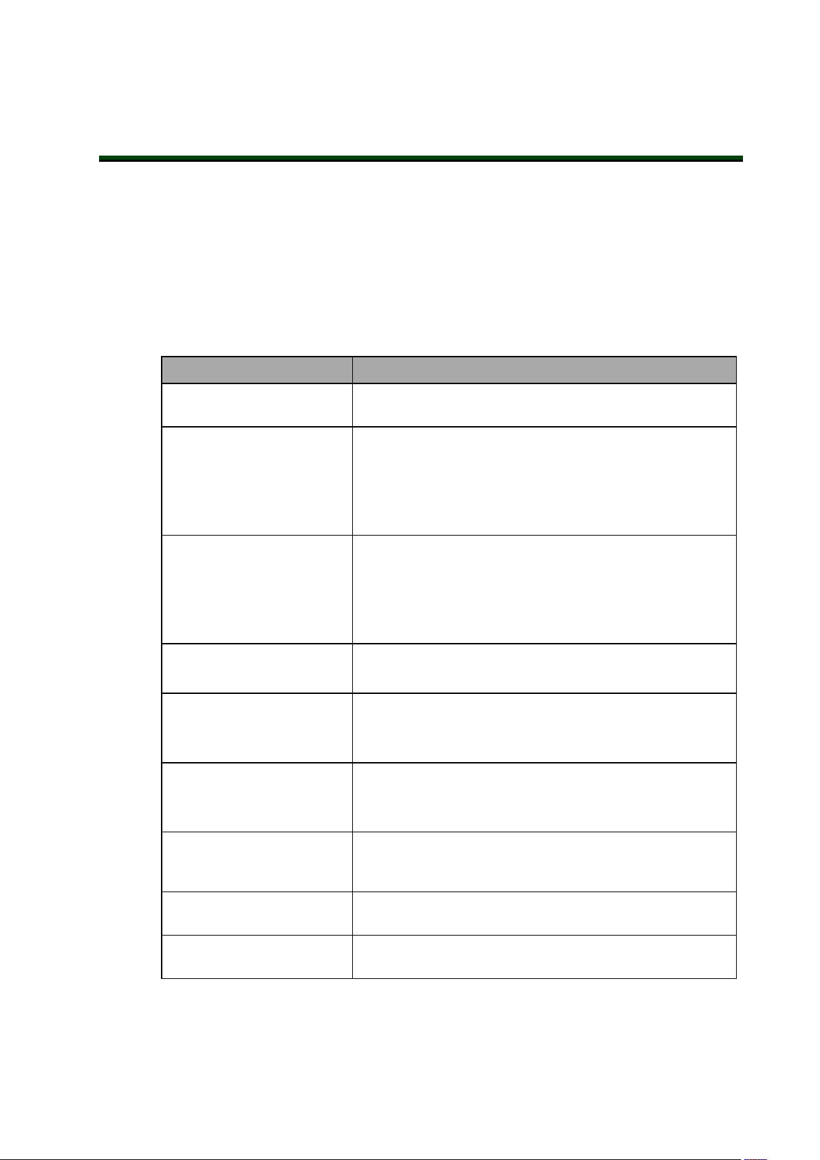
Pneumatic Pass-through Ports
The pneumatic pass-through ports on the back of Joint 1 are typically used for end-effector control. Internal air lines are routed internally through the robot to another set of matching connectors on the top of the outer link as shown below.
Additional Information: Refer to Technical Specifications on page 131 for more
information.
Figure 1-7. Pneumatic Pass-through ports on the back of Joint 1 (left) and Joint 2 (right)
Table 1-2. Pneumatic Pass-Through Port Descriptions
Item Description
A / C 4 mm ports
B / D 6 mm ports
Electrical Pass-through Connections
The electrical pass-through connectors on the back of Joint 1 are typically used for end-effector
sensing and control. Internal harnesses are routed through the robot to another set of mating
connectors on the top of the outer link as shown below.
Additional Information: Refer to Technical Specifications on page 131 for more
information.
18 eCobra 600 and 800 Robots with EtherCAT 24402-000 Rev B
Page 19

Chapter 1: Introduction
Figure 1-8. User Electrical Connectors on Joint 1 (left) and Joint 2 (right)
Item Description
A DeviceNet pass-through
B General purpose electrical pass-through.
IO Blox Connector
The IOBlox connector on Joint 1 provides an interface to addIOBlox expansion I/O modules
to a robot.
NOTE: Refer to Connecting Digital I/O to the System on page 67 and the IO Blox
User’s Guide (04638-000) for more information.
Figure 1-9. IOBlox Connector
24402-000 Rev B eCobra 600 and 800 Robots with EtherCAT 19
Page 20

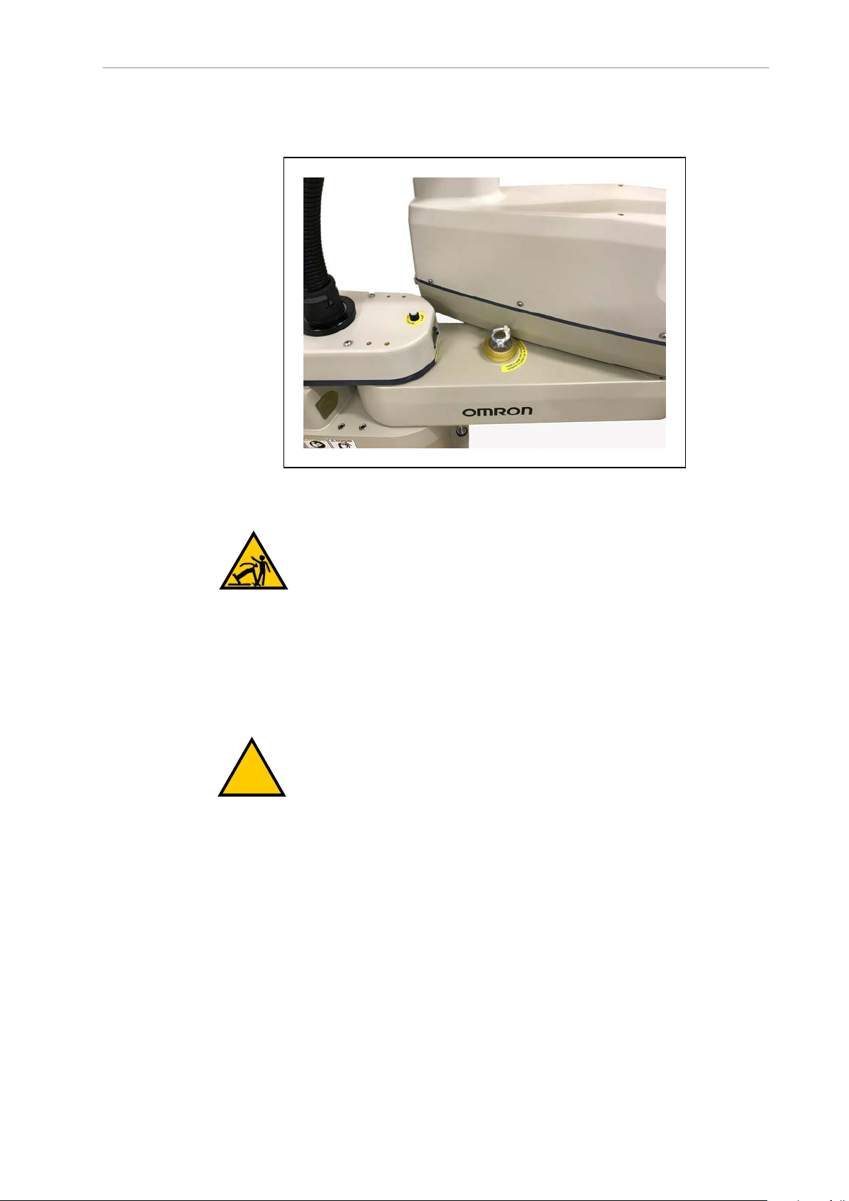
Solenoid Connector
The robot has been pre-wired to accommodate a bank of two 24 VDC solenoid valves. Power
for the internally mounted solenoid valves is accessible with a connector mounted inside the
outer link cover. This 4-pin connector provides the output signals for internally mounted solenoid valves. The solenoid connector location and pin details are provided below.
Additional Information: An optional Solenoid Valve Kit (part number 02853-
000) is available for use with the internal solenoid connector. Refer to Robot
Options on page 25 and Technical Specifications on page 131 for more information.
Figure 1-10. Solenoid Connector Location
Table 1-3. Solenoid Connector Pinout
Pin # Description Pin Location
1 Output 3001 (+24 VDC)
2 0 VDC
3 Output 3002 (+24 VDC)
4 0 VDC
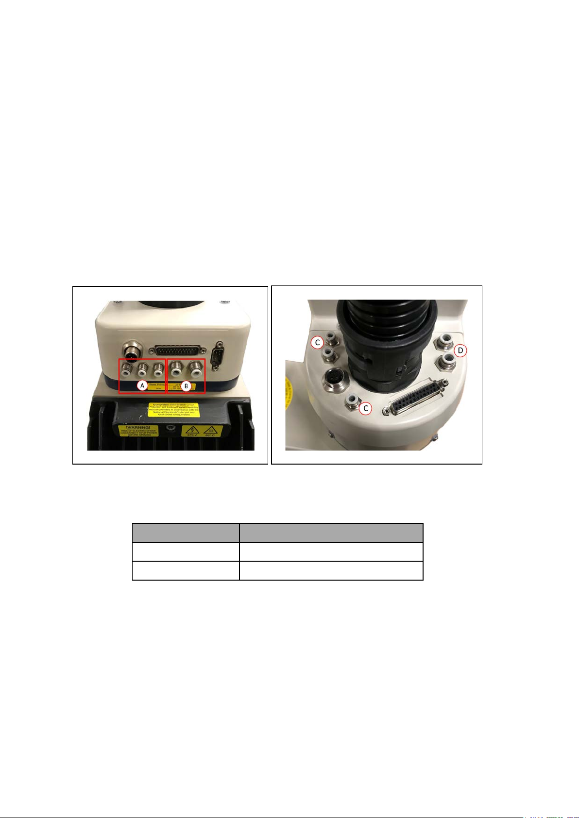
OP3/4 Connector
This 4-pin connector provides the output signals for a second set of optional robot hand valve
solenoids or other user-supplied devices. The OP3/4 connector location and pin details are
provided below.
20 eCobra 600 and 800 Robots with EtherCAT 24402-000 Rev B
Page 21
Chapter 1: Introduction
!
WARNING: Do not remove the J3-ENC or J4-ENC encoder cable connectors
that are located near the OP3/4 connector. If they are removed, the calibration
data will be lost and the robot must be factory recalibrated which requires special software and tools.
Additional Information: Technical Specifications on page 131 for more information.
Figure 1-11. OP3/4 Connector Location
Table 1-4. OP3/4 Connector Pinout
Pin # Description Pin Location
1 Output 3003 (+24 VDC)
2 0 VDC
3 Output 3004 (+24 VDC)
4 0 VDC
End of Arm Break-away Sensor Connector
The end of arm break-away sensor shutdown function provides a high power shutdown from
the outer link area. For example, if you want a break-away gripper to shut down robot high
power, this allows you disable high power through a user relay circuit inside the robot.
24402-000 Rev B eCobra 600 and 800 Robots with EtherCAT 21
Page 22

!
WARNING: Do not remove the J3-ENC or J4-ENC encoder cable connectors
that are located near the end of arm break-away sensor connector. If they are
removed, the calibration data will be lost and the robot must be factory recalibrated which requires special software and tools.
This is typically used with a break-away sensor at the end of arm tooling to immediately turn
OFF high power when the circuit becomes open. The end of arm break-away sensor connector
location and pin details are provided below.
Additional Information: Refer to End of Arm Break-away Sensor on page 26and
Technical Specifications on page 131 for more information.
IMPORTANT: When connecting a cable to the End of Arm Break-away Sensor
Connector, be careful to not dislodge or remove the encoder connectors nearby.
Figure 1-12. End of Arm Break-away Sensor Connector Location
Table 1-5. End-effector Break-away Connector Pin Details
Pin # Description Pin Location
1 Input
2 +24 VDC Supply
22 eCobra 600 and 800 Robots with EtherCAT 24402-000 Rev B
Page 23

Chapter 1: Introduction
!
EOAPWR Connector
The end of arm power (EOAPWR) connector is a 4-pin connector that provides 24 VDC power
and ground for end-of-arm tooling. The location of the EOAPWR connector and pin details are
provided below.
WARNING: Do not remove the J3-ENC or J4-ENC encoder cable connectors
that are located near the EOAPWR connector. If they are removed, the calibration data will be lost and the robot must be factory recalibrated which
requires special software and tools.
Figure 1-13. EOAPWR Connector Location
See the following table for the pinouts and the following section for the output specifications.
Table 1-6. EOAPWR Connector Pinout
Pin # Description Pin Location
1 24 VDC
2 Ground
3 24 VDC
4 Ground
24402-000 Rev B eCobra 600 and 800 Robots with EtherCAT 23
EOAPWR Connector
as viewed on robot
Page 24

Pin # Description Pin Location
Mating Connector:
Housing: AMP/Tyco #172167-1, 4-pin Mini-Universal Mate-N-Lok
Pins: AMP/Tyco #770985-1, Pin Contact, Mini-Univ. Mate-N-Lok
iCS-ECAT Robot Interface Panel
The iCS-ECAT includes the robot interface panel. It has connections for power (240 VAC, 24
VDC), communications, and other peripheral devices such as a pendant, IOBlox, or a Front
Panel..
Use the information below to understand all connection points for the iCS-ECAT robot
interfacepanel.
Figure 1-14. iCS-ECAT Robot Interface Panel
Item Meaning
A ACPower Supply Connector
Used for connecting 200-240 VAC, single-phase input power to the robot.
A connector is provided with the robot.
Refer to Connecting 200-240 VAC Power Cable on page 81
B DCPower Supply Connector
Used for connecting the user-supplied 24 VDC power to the robot.
A connector is provided with the robot.
Refer to Connecting the 24 VDC Cable to the Robot on page 78 for more
information.
C Ground Terminal
D XSYSTEM Connector
24 eCobra 600 and 800 Robots with EtherCAT 24402-000 Rev B
Page 25

Item Meaning
!
Refer to System Cable Installation on page 61
E EtherCAT Ports
Used for inbound and outbound EtherCAT communications.
Chapter 1: Introduction
F
G
H
Node ID Switches
Used to set the robot's EtherCATnodeID.
Refer to Setting the EtherCATNodeID on page 58
LEDs
Indicates the status of the EtherCAT connection.
Refer to EtherCAT Communications Description on page 102 for more information.
4-Position Mode Switches
Used to adjust the operating mode of the robot.
Refer to Robot Control Modes on page 104 for more information.
Additional Information: Switch 1 should remain in the NX / left
position. Functionality associated with switch 1 in the 3P / right
position is reserved for future use.
XBELTIO Connector
I
Used to connect up to two external belt encoders (eCobra Pro only) and IO Blox
external I/O. This requires the XBELTIO Adapter cable.
Refer to Basic System Cable Layout on page 61 for more information.
XBELTIO
J XIO Connector
Used for user I/O signals for peripheral devices.
Refer to Basic System Cable Layout on page 61 for more information.
1.3 Robot Options
This section describes the various options available for your eCobra robot.
WARNING: Ensure all optional equipment is installed properly and securely
fastened to the robot before operation. Failure to do so may result in personal
injury or equipment damage.
Solenoid Valve Kit
The Solenoid Valve Assembly (part number 02853-000) consists of two independent valvesmounted to a common manifold. Each valve has two output ports: A and B. The output ports
are arranged so that when Port A is pressurized, Port B is not pressurized. Conversely, when
Port B is pressurized, Port A is not pressurized.
24402-000 Rev B eCobra 600 and 800 Robots with EtherCAT 25
Page 26

The signals actuating the valves are directly switchable from the iCS-ECAT using software signals 3001 and 3002.
NOTE: Refer to the eV+3 Keyword ReferenceManual (Cat. No. I652), eV+3
User'sManual (Cat. No. I651), and Sysmac Studio Robot Integrated System Building
Function with Robot Integrated CPU Unit Operation Manual (Cat. No. W595) for
more information about robot signal control.
The supplied solenoids each require a nominal 75 mA at 24 VDC.
The air lines from Port A on each valve have factory-installed plugs at the solenoid assembly
so you can use the assembly as 3-way valves. If you need 4-way valves, remove the plugs.
The following image shows an installed SolenoidValveKit.
Additional Information: Refer to Solenoid Valve Kit Installation Procedure on
page 90 for more information.
Figure 1-15. Solenoid ValveKit Installed
End of Arm Break-away Sensor
The internal 2-pin end-of-arm break-away sensor connector provides a pair of contacts that
can be used for a user-supplied, break-away sensor at the end of the robot arm. The function is
disabled by default and you must enable it using the Sysmac Studio.
The break-away sensor requires a normally-closed circuit wired to Pins 1 and 2 of the connector. When the circuit is opened, the system will stop with a status code F1 (refer to Status
Codes Table on page 171 for more information).
Additional Information: Refer to End of Arm Break-away Sensor Connector on
page 21 for more information about the connector location.
26 eCobra 600 and 800 Robots with EtherCAT 24402-000 Rev B
Page 27

Chapter 1: Introduction
Pin 1 (input)
Pin 2 (+24 VDC)
Normally Closed
Switch
IMPORTANT: When connecting a cable to the end of arm break-away sensor
connector, be careful to not dislodge or remove the encoder connectors nearby.
The following figure shows a typical end-of-arm break-away sensor circuit.
Figure 1-16. End-of-arm break-away sensor Circuit
IO Blox
IO Blox units extend the robot's capabilities by providing expandable I/O capacity..
You can add up to 4 IO Blox units to the eCobra Standard model and up to 4 additional IO
Blox units (for a total of 8 units) to the eCobra Pro.
Additional Information: Refer to IO Blox Connections on page 68 and the IO
Blox User’s Guide (04638-000) for more information.
Figure 1-17. IO Blox
Optional I/O Items
The following optional items are available for use with digital I/O.
l
XIO Breakout Cable (part number 04465-000)
Refer to Optional Cables on page 33 for more information.
NOTE: This cable is not compatible with the XIO Termination Block
described below.
l
XIO Termination Block (part number 90356-40100)
Includes terminals for user wiring and I/O status LEDs. Connects to the XIO connector
with 2m cable.
24402-000 Rev B eCobra 600 and 800 Robots with EtherCAT 27
Page 28

T20 Pendant
The T20 pendant is an optional hand held device that allows you to move the robot, teach locations, and debug programs without a PC. The pendant can also be used to move the robot
before calibration has occurred.
Additional Information: Refer to the T20 Pendant User's Manual (Cat. No. I601)
for more information about operating a robot with the T20 pendant.
IMPORTANT: The T20 pendant can only communicate with the robot it is directly connected to.
Figure 1-18. T20 Pendant
IPC Application Controller
The IPCApplicationController can be added to your system to execute PackManager and
Robot VisionManager applications.
Refer to the following manuals for more information.
l AutomationControl Environment (ACE)Version 4 User'sManual (Cat. No. I633)
l NJ-series Robot Integrated CPU Unit User's Manual (Cat. No. O037)
l IPC Application Controller User’s Manual (Cat. No. I632)
28 eCobra 600 and 800 Robots with EtherCAT 24402-000 Rev B
Page 29

Chapter 1: Introduction
!
Figure 1-19. IPC Application Controller
Front Panel
The Front Panel is an optional device that provides the following functions.
l Setting the robot mode to manual or automatic. Refer to Robot Control Modes on page
104 for more information.
l Indicating the robot high power and system power state.
l Robot high power indicator burnout detection (see note below).
l Enabling robot high power. Refer to Enabling Robot High Power on page 106 for more
information.
l Emergency stop / disable robot high power.
Additional Information: Design of the factory-supplied Front Panel E-Stop is in
accordance with the requirements of IEC 60204-1 and ISO 13849.
IMPORTANT: If the Front Panel high power ON / OFF lamp (part number
27400-29006) fails, you might incorrectly assume that High Power is OFF and
the robot is safe. To prevent this, a failed lamp causes an error (-924) *Front
panel HIGHPOWERlamp failure* and locks out the High Power enabling until
you replace the lamp. Refer to the eV+3 User'sManual (Cat. No. I651) for more
information about error handling. Refer to Change Front Panel High-Power ON
Lamp on page 126 for more information about lamp replacement.
WARNING: PERSONALINJURYRISK
If you supply your own Front Panel, its design must comply with the requirements of IEC 60204-1 and ISO 13849. The E-Stop's push button must comply
with ISO 13850 (Clause 5.5.2).
24402-000 Rev B eCobra 600 and 800 Robots with EtherCAT 29
Page 30

Figure 1-20. Front Panel
!
!
Item Description
A XFP connector
Connects to the XFP connector on the XSYSTEM Adapter Cable.
(on the side of the Front Panel)
System 5 VDC Power-On LED
B
Indicates whether the robot is receiving power.
Manual mode
C
The system limits robot speed and torque so an operator can safely work near the
robotl. Manual mode initiates hardware and software limits to robot speed at no
more than 250 mm/sec.
There is no high speed motion available in Manual mode.
WARNING: PERSONALINJURYRISK
If an operator is going to be in the work cell with the switch in
Manual mode, the operator must carry an enabling device such as the
T20 pendant.
WARNING: PERSONALINJURYRISK
Whenever possible, perform manual mode operations with all personnel outside the workspace.
Automatic mode
D
Software programs control the robot allowing operation at full speed.
30 eCobra 600 and 800 Robots with EtherCAT 24402-000 Rev B
Page 31
Item Description
!
!
DANGER: PERSONAL INJURY RISK
In Automatic mode, the robot can move unexpectedly. Ensure all personnel remain clear of the cell when Automatic mode is enabled.
High Power ON/OFF Switch and Lamp
E
Controls high power, which is the flow of current to the robot motors. You can enable
high power by pressing and releasing the High Power switch twice. Once the High
Power ON/OFF lamp is blinking, you must press and release the button to enable
high power.
WARNING: PERSONALINJURYRISK
Disabling the High Power button violates IEC 60204-1. Do not alter its
use.
NOTE: If enabled, you must press the Front Panel button while it is
blinking (default time-out is 10 seconds). If the button stops blinking,
you must enable power again.
Chapter 1: Introduction
Emergency Stop Switch
F
A dual-channel, passive E-Stop that supports Category 3 CE safety requirements.
Pressing this button turns OFF high power to the robot motors.
NOTE: The Front Panel is required to enable power to the robot. To
operate without a Front Panel, you must supply the equivalent circuits.
Manual/Automatic Mode Switch
G
Switches between Manual and Automatic mode (figure shown in Automatic Mode).
Camera Bracket Kit
The eCobra Robot Camera Bracket Kit (P/N 95000-00100) provides a convenient way of mounting cameras to the outer link of the robot.
24402-000 Rev B eCobra 600 and 800 Robots with EtherCAT 31
Page 32

Camera Plate
Camera Brackets
Camera Channel
Camera
Mount
Figure 1-21. Camera Bracket Kit
The kit consists of the following items.
l One camera plate
l Two camera brackets
l One camera mount
l One camera channel
l M4 x 12 mm screws
l M4 flat washers
l M5 x 12 mm screws
Additional Information: Refer to Installing the Camera Bracket Kit on page 93
for more information.
Adjustable Hardstops
Optional adjustable hardstops are available to modify the robot's work envelope by installing
physical stops for Joint 1 and Joint 2.
The part number for the adjustable hardstop kit is 02592-000.
Additional Information: Refer to Installing Adjustable Hardstops on page 95 for
more information.
Table 1-7. Joint 1 Ranges for Adjustable Hardstops
Joint and Installation
Position
Joint 1, Position 1 ±50° Lower limit: – 49°
Hardstop
Value
Recommended SoftwareLimit
Settings
32 eCobra 600 and 800 Robots with EtherCAT 24402-000 Rev B
Page 33

Chapter 1: Introduction
Joint and Installation
Position
Joint 1, Position 2 ±88° Lower limit: – 87°
Joint 2, Position 1
Joint 2, Position 2
Joint 2, Position 3
Hardstop
Value
81° Lower limit: – 80°
±
± 51°
21° Lower limit: – 20°
±
Recommended SoftwareLimit
Upper limit: + 49°
Upper limit: + 87°
Upper limit: + 80°
Lower limit: – 50°
Upper limit: + 50°
Upper limit: + 20°
Optional Cables
The following table provides details about optional cables.
Table 1-8. Optional Cables
P/N
13463-000
Description
XBELT I/O Adapter Cable (600 mm)
The optional XBELT IO Adapter cable splits the XBELTIO port on the robot
interface panel into a belt encoder branch and an IO Blox branch, and an RS232 branch.
Settings
NOTE: You can use the FORCE / EXPIO connector on this cable
to connect a 2nd group of up to 4 IOBlox devices (eCobra Pro
only). For details on the pinouts for this cable, refer to Pinouts for
XBELT IO Adapter on page 66.
09443-000
Belt Encoder to M12 Y Adapter Cable (3 m)
This optional adapter cable splits the belt encoder connection on the XBELTIO
cable into two belt encoder branches.
NOTE: For details on using this cable, refer to XBELT IO Belt
Encoder Y Adapter Cable on page 65.
24402-000 Rev B eCobra 600 and 800 Robots with EtherCAT 33
Page 34

P/N
Description
04677-000
04465-000
EXPIO-to-IOBlox Cable (3 m)
This optional cable is used to connect IO Blox devices to the robot's EXPIO connector.
NOTE: For details on connecting IO Blox units to your system,
refer to IO Blox Connections on page 68.
XIO/TIN Cable (5 m)
This optional cable connects to the XIO connector on the robot interface panel
to add multiple I/O devices to the system without using an IOBlox unit.
IMPORTANT: This cable is not compatible with the XIO Termination Block.
Additional Information: Refer to XIOBreakout Cable Pinout on
page 34 for more information.
03695-000
XIO Cable (2 m)
The optional XIO cable is for connecting an XIO Termination Block to the XIO
port on the iCS-ECAT robot interface panel. For addtional details, refer to XIO
Termination Block on page 69.
XIOBreakout Cable Pinout
TheXIOBreakout cable pinouts are provided below.
Table 1-9. XIO Breakout Cable Wire Chart
Signal
Pin No.
Designation Wire Color
1 GND White
2 24 VDC White/Black
3 Common 1 Red
4 Input 1.1 Red/Black
34 eCobra 600 and 800 Robots with EtherCAT 24402-000 Rev B
Page 35

Signal
Pin 9Pin 1
Pin 18Pin 10
Pin 19
Pin 26
Pin No.
Designation Wire Color
5 Input 2.1 Yellow
6 Input 3.1 Yellow/Black
7 Input 4.1 Green
8 Input 5.1 Green/Black
9 Input 6.1 Blue
10 GND Blue/White
11 24 VDC Brown
12 Common 2 Brown/White
13 Input 1.2 Orange
14 Input 2.2 Orange/Black
15 Input 3.2 Gray
16 Input 4.2 Gray/Black
Chapter 1: Introduction
17 Input 5.2 Violet
18 Input 6.2 Violet/White
19 Output 1 Pink
20 Output 2 Pink/Black
21 Output 3 Light Blue
22 Output 4 Light Blue/Black
23 Output 5 Light Green
24 Output 6 Light Green/Black
25 Output 7 White/Red
26 Output 8 White/Blue
Shell Shield
24402-000 Rev B eCobra 600 and 800 Robots with EtherCAT 35
Page 36

Page 37

Chapter 2: Safety
!
!
!
!
This chapter describes the various alert icons used in this manual and their meaning,
provides important safety precautions for using OMRON industrial robots and their intended
uses, and gives guidance on proper disposal.
2.1 Dangers, Warnings, and Cautions
This section describes the various alert levels and icons which identify potentially hazardous
actions or situations
Alert Levels
There are three levels of safety warnings used in our manuals. In descending order of importance, they are:
DANGER: Identifies an imminently hazardous situation which, if not
avoided, is likely to result in serious injury, and might result in fatality or
severe property damage.
WARNING: Identifies a potentially hazardous situation which, if not avoided,
will result in minor or moderate injury, and might result in serious injury, fatality, or significant property damage.
CAUTION: Identifies a potentially hazardous situation which, if not avoided,
might result in minor injury, moderate injury, or property damage.
Alert Icons
Each alert consists of a standard warning triangle icon, a signal word, and a description of the
risk. In increasing severity, the signals words are: Caution, Warning, and Danger. The alert text
provides a description of the hazard and explains how you can prevent or avoid it.
Icon Meaning Icon Meaning
This is a generic alert icon. Any
specifics on the risk will be in
the text following the signal
word.
This identifies a hazardous electrical situation.
This identifies a potential
topple injury hazard.
This identifies a fire risk.
24402-000 Rev B eCobra 600 and 800 Robots with EtherCAT 37
Page 38

Icon Meaning Icon Meaning
!
This identifies a hazardous
burn-related situation.
This identifies a potential robot
impact risk.
Special Information
There are several types of notation used to call out special information.
IMPORTANT: Information to ensure safe use of the product.
NOTE: Information for more effective use of the product.
Additional Information: Offers helpful tips, recommendations, and best prac-
tices.
Version Information: Information on differences in specifications for different
versions of hardware or software.
2.2 Safety Precautions
This section provides important information about the safety precautions you must take to
ensure the safe operation of your robot system.
WARNING: PERSONAL INJURY/PROPERTY DAMAGE
These robots can cause serious injury or fatality, or damage to itself and other
equipment, if the following safety precautions are not observed:
l
If you install, operate, teach, program, or maintain the system, you must read this guide,
read the Robot Safety Guide, and complete a training course for your responsibilities in
regard to the robot.
Figure 2-1. Read Manual and Impact Warning Labels
l
All personnel who design the robot system must read this guide, read the Robot Safety
Guide, and must comply with all local and national safety regulations for the location in
which the robot is installed.
l
Never use the robot system for purposes other than described in Intended Use of the
Robot on page 40. Contact your local OMRON support if you are not sure of the suitability for your application.
l
You are responsible for providing safety barriers around the robot to prevent anyone
from accidentally coming into contact with the robot when it is in motion.
38 eCobra 600 and 800 Robots with EtherCAT 24402-000 Rev B
Page 39

Chapter 2: Safety
!
l
You must lock out and tag out power to the robot and its power supply before performing any maintenance.
2.3 What To Do In An Emergency
The following is important safety information for actions to take in an emergency.
Stopping the Robot
Press any E-Stop button (a red push-button on a yellow background) and then follow the
internal procedures of your company or organization for an emergency situation.
Fire Response
If a fire occurs, use CO2fire extinguisher to extinguish the fire.
Entrapment and Brake Release Button
In case of entrapment of a person by the robot, or any other emergency or abnormal situation,
a Brake Release button (above the Robot Status Display) allows you to manually position the
robot arms without enabling high power. When 24 VDC system power is ON, pressing this
button releases the brakes, which allows movement of the arms.
DANGER: PERSONAL INJURY RISK
This robot is not a collaborative robot. It requires a dedicated work area that
prevents personnel from coming into contact with the robot during operation.
2.4 Robot Behavior
This section provides important information about the devices used to limit robot movements.
Hardstops
If the robot runs into one of its hardstops, the robot’s motion will stop completely, the system
will generate an envelope error, and power will be cut to the robot motors.
The robot cannot continue to move after hitting a hardstop until you clear the error.
The robot’s hardstops can stop the robot at any speed, load, and maximum or minimum extension.
Limiting Devices
There are no dynamic or electro-mechanical limiting devices provided by OMRON Robotics
and Safety Technologies, Inc. The robot does not have safety-rated soft axis or space limiting.
However, users can install their own safety rated (category 0 or 1) dynamic limiting devices if
needed, that comply with ISO10218-1, Clause 5.12.2.
Singularities
Asingularity is a condition caused by the collinear alignment of two or more robot axes, resulting in unpredictable robot motion and velocities.
In the eCobra robot, any straight-line (MOVES) command sent to a fully-outstretched arm
Cartesian workspace boundary location is a singularity.
24402-000 Rev B eCobra 600 and 800 Robots with EtherCAT 39
Page 40

IMPORTANT: For safety reasons, you should always avoid all robot workspace
!
boundary locations.
2.5 Intended Use of the Robot
This section lists the intended uses, and prohibitions for use of OMRON industrial robots.
DANGER: PERSONAL INJURY RISK
This robot is not a collaborative robot. It requires a dedicated work area that
prevents personnel from coming into contact with the robot during operation.
The normal and intended use of these robots does not create hazards. The design and construction of eCobra robots was per the relevant requirements of IEC 60204-1.
These robots are for use in parts assembly and material handling for payloads up to 5.5 kg.
See Technical Specifications on page 131 for complete specifications. Refer to the Robot Safety
Guide for details on the intended use of OMRON robots.
Never use these robots in the following situations.
l
In the presence of ionizing or non-ionizing radiation
l
In hazardous environments with explosive gas or oil mist
l
In medical or life saving applications
l
In residential applications
l
Without performing a risk assessment
2.6 Additional Safety Information
OMRON provides other sources for more safety information:
Manufacturer’s Declarations
This lists all standards with which the robot complies. The Manufacturer’s Declarations for
your robot and other products are in the Manufacturer’s Declarations Guide (Cat. No 18305-000.
Robot Safety Guide
The Robot Safety Guide, which ships with every robot system, provides detailed information on
safety for OMRON robots. It also gives resources for more information on relevant standards.
T20 Pendant (Option)
The protective stop category for the pendant enable switch is category 1, which complies with
the requirements of ISO 10218-1.
The pendant's design is in accordance with the requirements of IEC 60204-1 and ISO 13849.
The E-Stop button complies with ISO 13850.
NOTE: OMRON does not offer a wireless pendant.
The manual control pendant can only move one robot at a time, even if your network contains
multiple robots.
40 eCobra 600 and 800 Robots with EtherCAT 24402-000 Rev B
Page 41

Chapter 2: Safety
2.7 Disposal
Dispose of in accordance with applicable regulations.
Customers can contribute to resource conservation and protecting the environment by the
proper disposal of Waste Electronics and Electrical Equipment (WEEE). All electrical and electronic products should be disposed of separately from the municipal waste system via designated collection facilities. For information about disposal of your old equipment, contact your
local OMRON support.
2.8 How Can I Get Help?
Contact your local OMRON Support, or refer to the corporate website:
http://www.ia.omron.com
24402-000 Rev B eCobra 600 and 800 Robots with EtherCAT 41
Page 42

Page 43
Chapter 3: Robot Installation
!
!
This chapter provides information about installing the robot and other necessary equipment.
3.1 Robot Installation Overview
This section provides an overview of the basic tasks that are required to install therobot.
WARNING: Robot installation must be completed before optional equipment
can be installed.
IMPORTANT: Prior to installing the robot, unpack and inspect the equipment.
Refer to Unpacking and Inspecting the Equipment on page 177 formore information.
Basic Installation Steps
Step Task Reference
1 Mount the robot. Mounting an eCobra Robot on page 43
2 Install the tool flange. Install the Tool Flange on page 46
3 Installing the Front Panel. Installing the Front Panel on page 47
4 Install user-supplied safety equip-
ment.
5 Set theEtherCATNode Address. Setting the EtherCATNodeID on page 58
6 Make robot system cable con-
nections.
7 Install any robot optional hard-
ware.
8 Verify the installation. Verifying Installation on page 99
Table 3-1. Installation Overview
Installing User-Supplied Safety Equipment on
page 49
System Cable Installation on page 61
Optional Equipment Installation on page 87
3.2 Mounting an eCobra Robot
This section describes the mounting procedure for the eCobra robot.
WARNING: PERSONALINJURYORPROPERTYDAMAGERISK
Only allow qualified service personnel to install or service the robot.
24402-000 Rev B eCobra 600 and 800 Robots with EtherCAT 43
Page 44

Mounting Surface
Mount eCobra robots on a smooth, flat, level surface that is rigid enough to prevent vibration
and flexing during robot operation. OMRON recommends a 25 mm thick steel plate mounted
to a rigid tube frame. The following figure shows the mounting hole pattern.
The underside of the base has a slot (A above) and hole (B above) you can use as locating
points for dowel pins in the mounting surface. Using locating pins allows you to remove and
reinstall the robot in the same position.
IMPORTANT: Excessive vibration or mounting flexure degrades robot performance.
Figure 3-1. Mounting Hole Pattern for eCobra Robots (units are in mm)
Mounting Procedure
Use the following procedure to mount the robot.
1.
Use the dimensions in the previous figure, drill and tap the mounting surface for four
M12 - 1.75 x 36 mm (or 7/16 - 14 UNC x 1.50 inch) machine bolts (user-supplied).
2.
If you are using dowel pins for locating the robot, insert those in the mounting surface.
44 eCobra 600 and 800 Robots with EtherCAT 24402-000 Rev B
Page 45
Chapter 3: Robot Installation
!
3.
While the robot is still bolted to the transportation pallet, connect a crane or hydraulic
lift to the eye bolt at the top of the inner link. Refer to the following figure.
Figure 3-2. Lifting Eye Bolt
WARNING: PERSONALINJURYORPROPERTYDAMAGERISK
Do not lift the robot at any point other than the eye bolt, or extend the
robot’s inner or outer links until the robot is secured in position. Failure
to comply could result in the robot falling and causing either personnel
injury or equipment damage.
4.
Remove the four bolts securing the robot base to the pallet.
Retain these bolts for possible later relocation of the equipment.
5.
Lift the robot and position it directly over the mounting surface.
WARNING: Always use at least two people when lifting the robot. Do
not attempt to extend robot inner or outer links until you have firmly
secured the robot in position. Failure to comply could result in the robot
falling and causing either personnel injury or equipment damage.
6.
Slowly lower the robot, align the base with the tapped holes in the mounting surface
and dowel pins, if used.
NOTE: The robot’s base is aluminum and can dent easily if bumped against a
harder surface.
7.
To eliminate the risk of toppling, screw in one bolt, finger-tight.
8.
Verify that the robot's base is squarely mounted (cannot rock back and forth) before
inserting and tightening the remaining mounting bolts.
9.
Install the user-supplied mounting bolts and washers. Tighten bolts to the torque
24402-000 Rev B eCobra 600 and 800 Robots with EtherCAT 45
Page 46
specified in the following table.
Table 3-2. Torque Specifications for Mounting Bolts
Standard Size Specification Torque
Metric M12 x 1.75 ISO Property Class 8.8 85 N·m
SAE 7/16-14 UNC SAE J429 Grade 5 or ASTM A449 65 ft-lb
WARNING: TOPPLEINJURYHAZARD
The robot's center of mass can cause the robot to fall over if the robot is
not secured with the mounting bolts.
NOTE: Check the mounting bolts one week after initial installation, and then
recheck every 6 months. See Maintenance on page 111 for periodic maintenance.
3.3 Install the Tool Flange
This section provides information to install the tool flange.
The tool flange, which you mount on the robot's quill, is the attachment point for all external
tooling and end-effectors that allow the robot to perform work.
To ensure proper tool flange alignment with the grooves on the quill, there is a setscrew on the
flange that holds the rotational position of the flange on the quill shaft (refer to the following
figure). A steel ball behind the setscrew contacts the shaft in one of the quill's vertical-spline
grooves to keep the flange aligned.
Additional Information: For flange dimensions, hole pattern, and location of
flange ground point, refer to Tool Flange Dimensions on page 149.
Figure 3-3. Tool Flange
46 eCobra 600 and 800 Robots with EtherCAT 24402-000 Rev B
Page 47
Chapter 3: Robot Installation
!
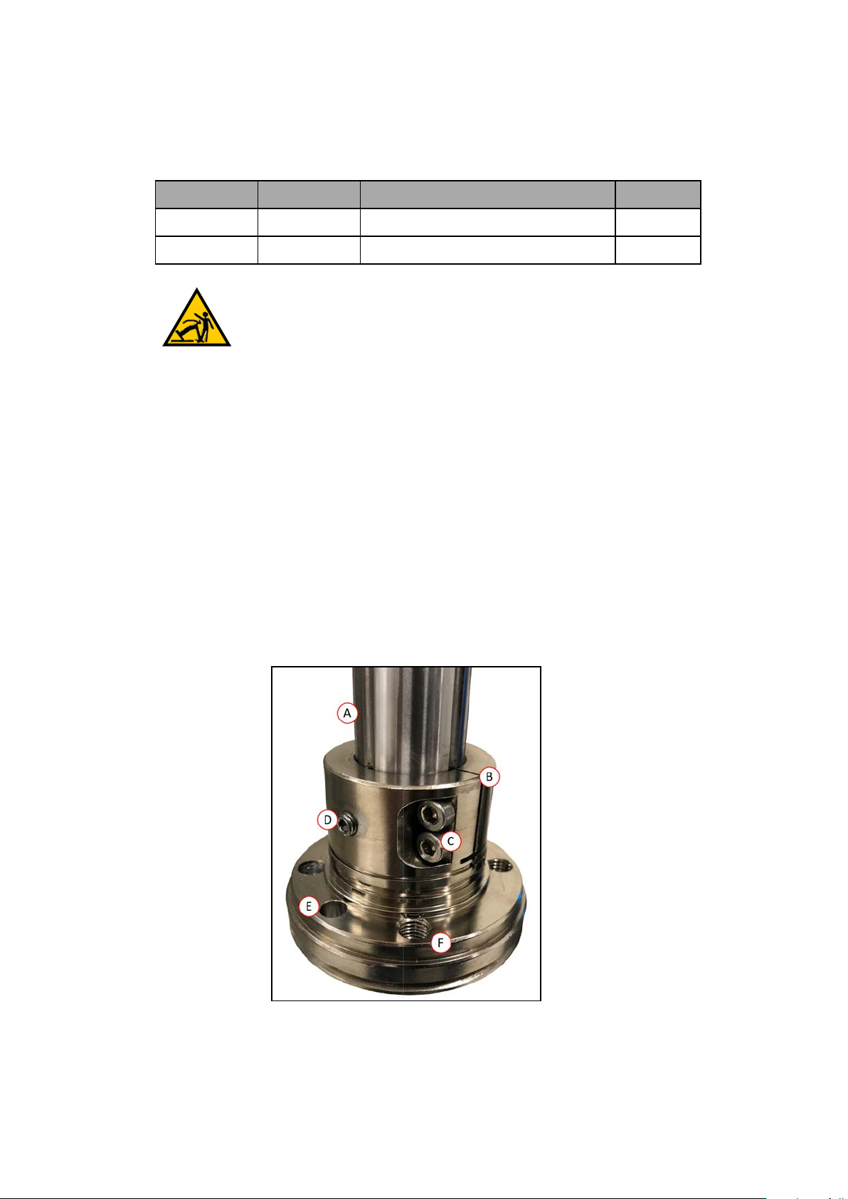
Figure 3-4. Tool Flange Details
Callout Meaning Callout Meaning
A Quill shaft
B Tool flange assembly
C M4 Socket-head cap screws F M6 X 1-6H Thru (x4)
Tool Flange InstallationProcedure
Use the following procedure to install the tool flange.
1.
Make sure the steel ball is in the setscrew hole inside the flange. Hold it in place with
your finger as you get ready to install the flange.
2.
Slide the flange up on the quill shaft as far as it will go, and rotate until the setscrew is
lined up with the original vertical groove.
3.
Support the flange while using a 2.5 mm hex wrench to tighten the setscrew to finger
tight. Do not over-tighten the setscrew. This would cause the flange to be off-center from
the quill shaft.
4.
Use a socket driver to tighten one of the socket-head screws part of the way, then tighten
the other one the same amount. Alternate between the two screws so there is even pressure on both. The torque specification for each screw is 8 N·m.
3.4 Installing the Front Panel
D Setscrew
E Dowel pin hole
Use the information provided in this section to install the Front Panel.
When mounting the Front Panel, you must select an installation location outside the robot's
workcell where it can immediately be reached in an emergency.
Possible mounting locations include immediately next to the workcell gate, on a nearby desk,
or other readily accessible location.
Additional Information: Refer to Front Panel Dimensions on page 150 for more
information.
DANGER: A remote High Power push-button must be installed outside of the
robot's workspace.
Connecting the Front Panel
You can connect the Front Panel either directly to the XFP connector on the XSYSTEM cable
(A), or to the Front Panel cable (B).
24402-000 Rev B eCobra 600 and 800 Robots with EtherCAT 47
Page 48

Figure 3-5. Front Panel Connections
!
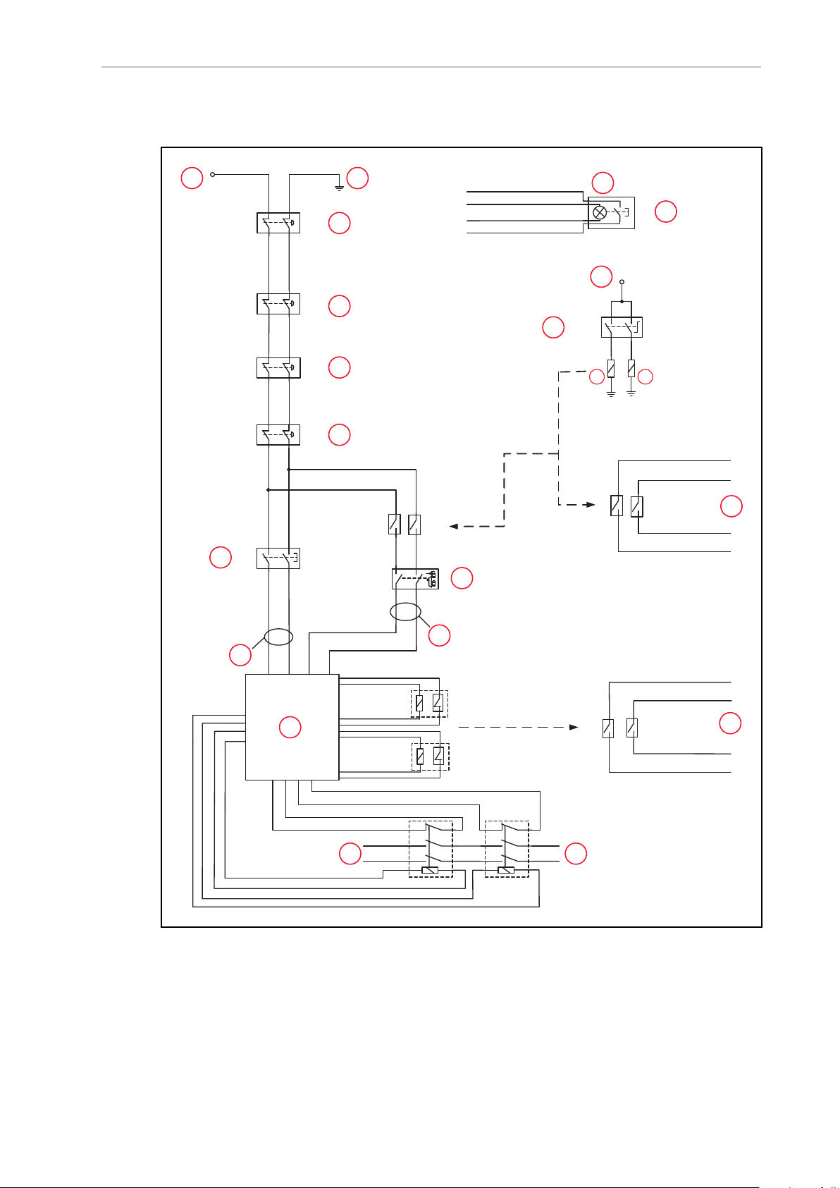
Front Panel Schematic
Use the following diagram to understand all Front Panelelectrical connections.
DANGER: PERSONAL INJURY RISK
If you supply your own Front Panel E-Stop, its design must comply with the
requirements of IEC 60204-1 and ISO 13849. The E-Stop's push button must
comply with ISO 13850.
48 eCobra 600 and 800 Robots with EtherCAT 24402-000 Rev B
Page 49

Chapter 3: Robot Installation
ESTOPSRC
24 VS
5 VD
D
SYSPWRLT 7
6
5
4
2
3
1
17
16
8
10
9
11
12
13
14
15
XFP
15PDSUBM
MANUALSRC1
HIPWRREQ
MANUALRLY2
MANUALRLY1
HIPWRLT
ESTOPFP2
ESTOPFP1
HPLT5V
NC
MANUALSRC2
MANUALSRC1
SW1
MANUALRLY2
MANUALRLY1
MANUALSRC2
24 VS
SWL1
HIPWRREQ
HPLT5 V
HIPWRLT
D
ESTOPSRC
SW2
ESTOPFP2
ESTOPFP1
5 VD
D
2-PIN_MINI
SYSPWRLT
A B C D
!
Figure 3-6. Front Panel Schematic showing the System Power LED (A), Manual/Auto Switch (B), High
Power On/Off (C), and Emergency Stop (D) circuits
IMPORTANT: Disabling the High Power button violates IEC 60204-1. We
strongly recommend that you not alter the use of the High Power button.
3.5 Installing User-Supplied Safety Equipment
You are responsible for properly installing safety equipment to protect personnel from unintentionally coming in contact with the robot. Depending on the design of the workcell, you can
use safety gates, light curtains, emergency stop devices, and other safety equipment to create a
safe environment.
WARNING: Installing, commissioning, or operation of any robot without
adequate safety equipment is strictly prohibited. This equipment must be compliant with all applicable and local standards. Failure to install suitable safety
equipment could result in injury or death.
Additional Information: Refer to the Robot Safety Guide (Cat. No. I590) for more
The user-supplied safety and power-control equipment connects to the system through the
XUSR and XFP connectors on the XSYSTEM cable. The XUSR connector (25-pin) and XFP (15pin) connector are both female D-sub connectors. Refer to the following sections for safety
equipment connection details.
Contacts on XUSR Connector
Use the information in the following table to understand the signals provided on the XUSR
connector.
information.
24402-000 Rev B eCobra 600 and 800 Robots with EtherCAT 49
Page 50

Table 3-3. XUSRConnectorSignals
Pin
Pairs
Description Comments
Voltage-Free Contacts Provided by Customer
1, 14 User E-Stop CH 1 (mushroom
push-button, safety gates, etc.)
2, 15 User E-Stop CH 2 (same as pins
N/C (Normally Closed) contacts, Shorted if
NOT Used
N/C contacts, Shorted if NOT Used
1, 14)
3, 16 Line E-Stop (used for other robot or
N/C contacts, Shorted if NOT Used
assembly line E-Stop interconnection. Does not affect E-Stop
indication (pins 7, 20))
4, 17 Line E-Stop (same as pins 3, 16) N/C contacts, Shorted if NOT Used
5, 18 Muted safety gate CH 1 (causes E-
N/C contacts, Shorted if NOT Used
Stop in Automatic mode only)
6, 19 Muted Safety Gate CH 2 (same as
N/C contacts, Shorted if NOT Used
pins 5, 18)
Voltage-Free Contacts provided by eCobra
7, 20 E-Stop indication CH 1 Contacts are closed when Front Panel,
pendant, and userE-Stops are not tripped
8, 21 E-Stop indication CH 2 (same as
pins 7, 20)
9, 22 Manual or Automatic indication
CH 1
10, 23 Manual or Automatic indication
CH 2
11, 12,
No connection
13, 24,
25
Contacts are closed when Front Panel,
pendant, and userE-Stops are not tripped
Contacts are closed in Automatic mode
Contacts are closed in Automatic mode
50 eCobra 600 and 800 Robots with EtherCAT 24402-000 Rev B
Page 51

Chapter 3: Robot Installation
Contacts on XFP Connector
Use the information in the following table to understand the signals provided on the XFP connector.
Table 3-4. XFP Connector Signals
Pin
Pairs
Description Requirements for User-
Supplied Front Panel
Voltage-Free Contacts Provided by Customer
1, 9 Front Panel E-Stop CH 1 User supplies N/C contacts
2, 10 Front Panel E-Stop CH 2 User supplies N/C contacts
3, 11 Remote Manual/Automatic switch CH 1.
Manual = Open Automatic = Closed
4, 12 Remote Manual/Automatic switch CH 2.
Manual = Open Automatic = Closed
Optional - jumper closed for
Auto Mode-only operation
Optional - jumper closed for
Auto Mode-only operation
6, 14 Remote High Power on/off momentary push-button User supplies momentary
push-button to enable High
Power to system
Non-voltage-Free Contacts
5, 13 System-Supplied 5 VDC and GND for High Power
On/Off Switch Lamp
User supplies lamp, or use 1
W, 47 ohm resistor - system
will not operate if not
present
a
7, 15
Controller system 5 V power on LED, 5 V, 20mA Optional - indicator only
8 No connection
See Figure 3-6. for a schematic diagram of the Front Panel.
a
Do not inadvertently connect 24 VDC signals to these pins as that will damage the elec-
tronics.
NOTE: Underwriters Laboratory evaluated the system with an OMRON Front
Panel. Using a substitute front panel could void UL compliance.
Remote Pendant Signals on the XMCPConnector
Use the information in the following table to understand the remote pendant signals provided
on the XMCP connector.
24402-000 Rev B eCobra 600 and 800 Robots with EtherCAT 51
Page 52

Table 3-5. Remote Pendant Connections on the XMCP Connector
Pin XMCP
(15-Pin D-Sub)
Description
1, 9 Pendant E-Stop Push-button CH 1
2, 10 Pendant E-Stop Push-button CH 2
3, 11 Pendant Enable CH 1 (Hold-to-run)
4, 12 Pendant Enable CH 2 (Hold-to-run)
13 Serial GND/Logic GND
7 Pendant TXD: “eV+to Pendant TXD”
8 Pendant RXD: “eV+to Pendant RXD”
14 No connection
15 No connection
Shield Shield GND
6 24 VDC
5 No connection
The preceding table gives descriptions of this circuit's functionality.
The following figure shows an E-Stop diagram for the system.
52 eCobra 600 and 800 Robots with EtherCAT 24402-000 Rev B
Page 53
E-Stop Circuits on XUSR and XFP Connectors
ES1
ES2
XSYSTEM-31
(XFP-1)
XSYSTEM-20
(XFP-9)
(XPND-7)
XSYSTEM-24
(XPND-24)
(XUSR-1)
(XUSR-14)
XSYSTEM-13
(XUSR-3)
(XPND-9)
XSY
STEM-8
(XPND-26)
XSYSTEM-32
(XFP-2)
(XFP-10)
(XPND-6)
(XPND-23)
(XUSR-2)
(XUSR-15)
XSYSTEM-43
(XUSR-4)
XSYSTEM-39 (XUSR-17)
XSYSTEM-9 (XUSR-16)
(XPND-8)
XSYSTEM-38
(XPND-25)
XSYSTEM-29 (XUSR-18)
XSYSTEM-44 (XUSR-19)
ES1
ES2
SR1 SR2
AM2 AM1
XSYSTEM-14
(XUSR-5)
XSYSTEM-30
(XUSR-6)
XSYSTEM-33 (XFP-13)
XSYSTEM-3 (XFP-5)
XSYSTEM-31 (XFP-6)
XSYSTEM-34 (XFP-14)
XSYSTEM-5
(XFP-4)
(XFP-3)
XSYSTEM-19
(XFP-12)
XSYSTEM-4
(XFP-11)
XSYSTEM-12 (XUSR-9)
XSYSTEM-28 (XUSR-10)
AM2
AM1
XSYSTEM-42 (XUSR-23)
XSYSTEM-27 (XUSR-22)
XSYSTEM-26 (XUSR-8)
XSYSTEM-10 (XUSR-7)
XSYSTEM-25 (XUSR-20)
XSYSTEM-40 (XUSR-21)
AM2 AM1
6 V, 1.2 W
G
B
A
C
D
F
I I
J
L
M
N
O
P
Q
R
H
K
S
A
E
Chapter 3: Robot Installation
Figure 3-7. E-Stop Circuit on XUSR and XFP Connectors
24402-000 Rev B eCobra 600 and 800 Robots with EtherCAT 53
Page 54

Key Meaning Key Meaning
A ESTOP 24 VDC Source K Auto/Manual Output
B Bulb, 6 V, 1.2 W L T20 Pendant Enable
C Front Panel High Power
ON/OFF
M Muted Safety Gate - Active in Auto mode
only (Jumper closed when not used)
D Front Panel E-Stop Pushbutton N Manual Mode Path
E T20 ESTOP Pushbutton O Auto Mode Path
F Front Panel Auto/Manual Key-
switch
P Force-Guided Relay Cycle Check Control
Circuit
G E-Stop Ground Q User E-Stop Output
User E-Stop and Gate Interlock
H
NOTE: Jumper closed when not used; MUSTopen both channels independently if used.
Coil R Single-Phase ACInput, 200-240 VAC
I
J LINEE-Stop (External User E-
Stop System)
S High Power to Amplifiers (Internal Con-
nections)
Emergency Stop Circuits
The information in this section describes emergency stop circuits used with the robot system.
NOTE: All pin numbers in this section correspond to the wiring diagram
shown in Figure 3-7.
The XSYSTEM cable provides connections for Emergency Stop (E-Stop) circuits on the XUSR
and XFP connectors. This means the controller system can duplicate E-Stop functionality from
a remote location using voltage-free contacts. Refer to Figure 3-7. .
The XUSR connector provides external two-channel E-Stop input on pin pairs 1, 14 and 2, 15.
The XFP connector provides two-channel E-Stop input on pin pairs 1, 9 and 2, 10.
NOTE: Short these pins if not used. If used, both channels must open independently. Although an Emergency Stop will occur, the controller will flag an
error state if one channel is jumpered closed and the other channel is opened. It
will also flag an error state if the channels are shorted together.
User E-Stop Indication Contacts - Remote Sensing of E-Stop
These contacts provide a method to indicate the status of the ESTOP chain, including the Front
Panel Emergency Stop push-button, the pendant Emergency Stop push-button, and the User
Emergency Stop Contacts. Refer to items D, E, H, J, and Qin Figure 3-7.
NOTE: These contacts do not indicate the status of any connections below the
User E-Stop contacts, so they will not indicate the status of the Line E-Stop, MCP
ENABLE, or the Muted Safety gate. If you have a specific need for this function,
contact your local OMRON support for information on alternate indicating
modes.
54 eCobra 600 and 800 Robots with EtherCAT 24402-000 Rev B
Page 55

Chapter 3: Robot Installation
!
Two pairs of pins on the XUSR connector (pins 7, 20 and 8, 21, Figure 3-7. ) provide voltagefree contacts, one for each channel, to indicate whether the E-Stop chain on that channel, as
described above, is closed. In normal operation (no E-Stop), both switches are closed on each
redundant circuit. You can use these contacts to generate an E-Stop for other equipment in the
workcell. The load on the contacts must not exceed 40 VDC or 30VAC at a maximum of 1 A.
NOTE: Per ISO 13849 operation, a redundant, cyclically-checked, positive-drive
safety relay circuit for Category 3 PL-d provides these voltage-free circuits (refer
to Figure 3-7. and Figure 3-6. for the user E-Stop circuitry).
Line E-Stop Input (KEY: J)
The XUSR connector on the controller contains a two-channel Line E-Stop input for workcell,
production line, or other equipment emergency-stop inputs. Refer to item Jin Figure 3-7.
Generally, the user E-Stop Indication contact outputs are used to generate an emergency stop
in such external equipment. A lock-up could occur if you were to wire the same equipment’s
outputs into the user E-Stop input (that is, in series with the local robot’s E-Stop push-buttons).
The Line E-Stop input comes into the circuit at a point where it cannot affect the user E-Stop
indication relays and will not cause such a lock-up situation.
For any situation where two systems should be cross-coupled, for example, the user E-Stop
indication of one controller is to be connected to the input of another controller, the Line E-Stop
input is the point to connect the other controller’s output contacts. See Figure 3-7. for more
information.
IMPORTANT: Do not use the Line E-Stop for devices such as local E-Stop pushbuttons. Their status should be reported to the outside on the local user E-Stop
indication output contact while the Line E-Stop inputs will not.
Muted Safety Gate E-Stop Circuitry
Two pairs of pins on the XUSR connector provide connections for a safety gate, allowing
access to the workspace of the robot in Manual mode only. Refer to items Mand L in Figure 3-
7. .
The muted capability is useful for a situation where a shutdown must occur if the cell gate is
opened in Automatic mode, but you need to open the gate in Manual mode. If the mute gate is
opened in Automatic mode, the robot defaults to Manual mode operation when power is reenabled. In muted mode, the gate can be left open for personnel to work in the robot cell.
However, safety is maintained because of the speed restriction.
IMPORTANT: It is up to the user to determine if teaching the robot in Manual
Mode by qualified personnel, wearing safety equipment, and carrying a pendant,
is allowable under local regulations. The E-Stop functionality can be muted in
Manual mode and careful consideration should be taken accordingly. Refer to
the Robot Safety Guide (Cat. No. I590) for more information.
CAUTION: PERSONALINJURYRISK
If you want the cell gate to always cause a robot shutdown, wire the gate
switch contacts in series with the user E-Stop inputs. Do not wire the gate
switch into the muted safety gate inputs.
24402-000 Rev B eCobra 600 and 800 Robots with EtherCAT 55
Page 56

Remote Manual Mode
!
!
!
The Front Panel provides for a Manual Mode circuit.
Additional Information: Refer to Remote High Power ON / OFF Control on page
56for further details about the user Remote Manual Mode circuitry.
You must incorporate either the Front Panel, or a user-supplied panel into the robot workcell
circuitry to provide a single point of control (the pendant) when the controller is placed in
Manual mode.
You may need to turn OFF certain workcell devices, such as PLCs or conveyors, when the operating mode switch is set to Manual mode. This is to ensure that the robot controller does not
receive commands from devices other than from the pendant (the single point of control in
this case).
Controlling the Manual / Automatic mode selection from other control equipment might
require a custom splitter cable or complete replacement of the Front Panel. Refer to the Front
Panel Schematic on page 48. In this situation, connect a pair of contacts in series with the
Front PanelManual / Automatic mode contacts. Both the Front Panel and the user contacts
need to be closed to allow Automatic mode.
WARNING: PERSONALINJURYRISK
Do not connect user-supplied Manual / Automatic contacts in parallel with the
Front Panel switch contact. This would violate the single point of control principle and might allow Automatic (high-speed) mode to be selected while an
operator is in the cell.
User Manual/Auto Indication
Two pairs of pins on the XUSR connector provide a voltage-free
contact to indicate whether the Front Panel and/or remote Manual / Automatic switches are
closed. Refer to item K in Figure 3-7. You can use these contacts to control other mechanisms
(for example, conveyor, linear modules, etc.) when Manual mode is selected.
IMPORTANT: The load on the contacts should not exceed 40 VDC or 30 VAC at
a maximum of 1 A.
WARNING: PERSONAL INJURY HAZARD
If you suspended any safeguards, you must return them to full functionality
before selecting Automatic Mode.
Remote High Power ON / OFF Control
There are two methods to provide high power ON / OFFcontrol in a remote location as
described below.
DANGER: A High Power push-button must be installed outside of the robot's
workspace.
56 eCobra 600 and 800 Robots with EtherCAT 24402-000 Rev B
Page 57
Chapter 3: Robot Installation
!
Extend the Front Panel ConnectionCable
The easiest and most effective way to provide the high power ON / OFF control in a remote location is to mount the Front Panel in the desired location with an extension cable. This method
allows you to relocate the Front Panel high power ON / OFF switch to a more convenient location. Implementation of this method must conform to EN standard recommendations.
NOTE: European standards require that a remote High Power push-button be
located outside of the robot's workspace.
You can build an extension cable to place the Front Panel in a remote location. The extension
cable must conform to the following specifications.
l
Wire Size: must be 26 AWG (0.13 mm2) or larger.
l
Connectors: must be 15-pin, standard D-sub male and female.
l
Maximum cable length is 10 meters.
IMPORTANT: Though the XMCP and XFP connectors can be interchanged
without electrical damage, neither the Front Panel nor the pendant will work
properly unless they are plugged into the correct connector.
Control High Power from Other Equipment
Controlling high power ON / OFF from other control equipment or from a location other than
the Front Panel requires a custom splitter cable. In this situation, place a second momentary
contact for high power ON / OFFin parallel with the Front Panel push-button contact. This
second contact should be suppressed when in Manual mode.
Additional Information: Refer to Front Panel Schematic on page 48 for more
information.
WARNING: PERSONALINJURYRISK
To fulfill the “Single Point of Control” requirement, do not place the Manual/Automatic and High Power On controls in multiple locations. After putting
the robot into Manual mode, the operator should remove the key for safety purposes.
Pins 6, 14 and 5, 13 of the XFP connector provide this remote capability. Pins 5, 13 provide
power for the lamp, +5 VDC and ground, respectively. Pins 6, 14 are inputs for voltage-free normally-open contacts from a user-supplied momentary push-button switch. Refer to items B
and C in Figure 3-7.
Using a User-Supplied Control Panel
You can create a user-supplied control panel that performs the same functions as the optional
Front Panel. The optional Front Panel contains only switches and lights(no active components).
Additional Information: Refer to Front Panel Schematic on page 48 for internal
wiring information.
24402-000 Rev B eCobra 600 and 800 Robots with EtherCAT 57
Page 58

IMPORTANT: Underwriters Laboratory evaluated the system with an OMRON
!
Front Panel. If you provide a substitute, the system may no longer be UL compliant.
IMPORTANT: Though the XMCP and XFP connectors can be interchanged
without electrical damage, neither the Front Panel nor the pendant will work
properly unless they are plugged into the correct connector.
Remote Pendant Usage
You can build an extension cable to place the pendant in a remote location. The extension
cable must conform to the following specifications:
l
Wire Size: must be 26 AWG (0.13 mm2) or larger.
l
Connectors: must be 15-pin, standard D-sub male and female.
l
Maximum cable length is 10 meters.
CAUTION: EQUIPMENT DAMAGE HAZARD
Do not modify the cable that is attached to the pendant. This could cause
unpredictable behavior from the robot system.
3.6 Setting the EtherCATNodeID
The EtherCATNode ID(address) can be set with two methods.
Use Hardware Switches on the Robot
Use the hardware switches on the robot interface panel to set an explicit EtherCATnode ID for
the robot. Refer to Setting the EtherCATNode ID UsingHardware Switches on page 59 for
more information.
Use Sysmac Studio Software
When the EtherCATnode ID is set with Sysmac Studio, it is retained in non-volatile memory
and will persist after subsequent power cycles.
Additional Information: Refer to the Sysmac Studio Version 1 Operation Manual
(Cat. No. W504) for more information about setting the EtherCATnodeID with
software.
IMPORTANT: When using Sysmac Studio to set the EtherCATnode ID, ensure
the switches are set to the default 0 positions as shown in the figure below. If the
switches are set to a non-zero value, the switch positions will dictate the
EtherCATnode ID and software adjustment of this value is not possible.
58 eCobra 600 and 800 Robots with EtherCAT 24402-000 Rev B
Page 59
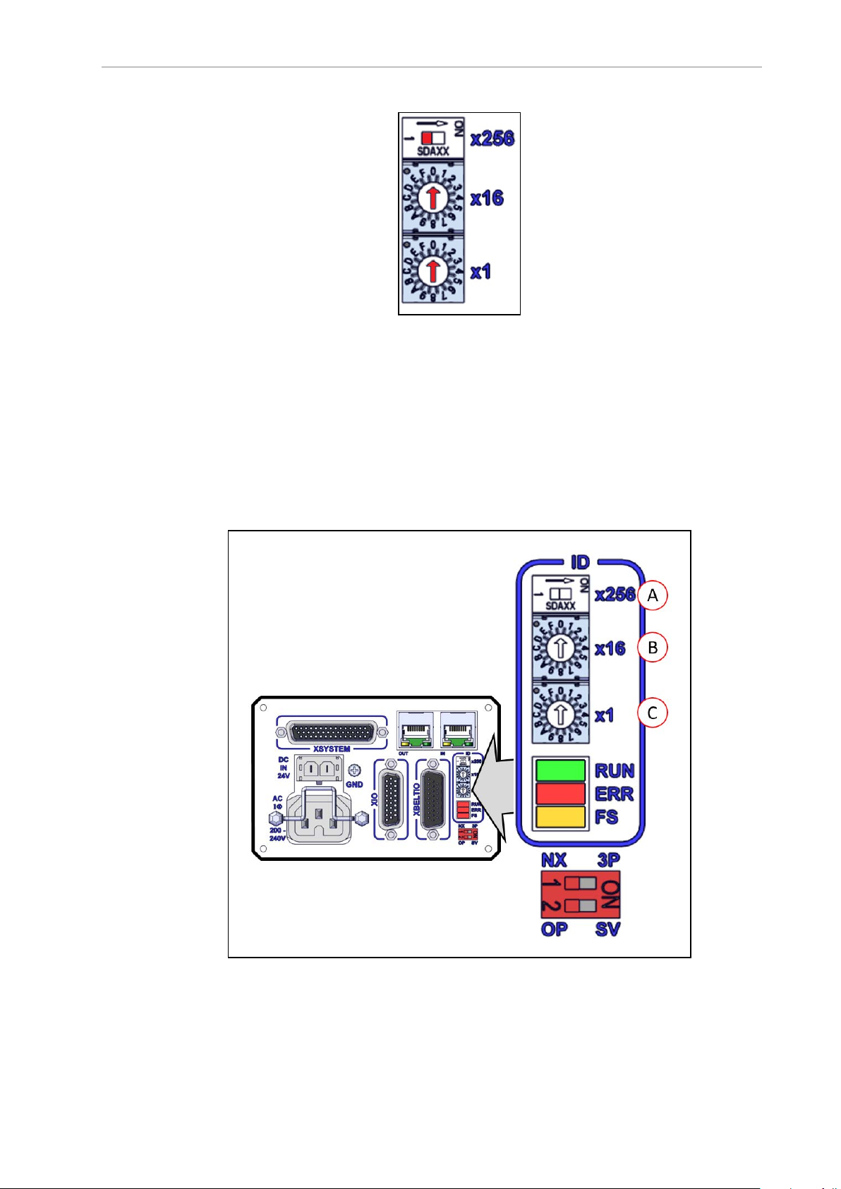
Chapter 3: Robot Installation
Figure 3-8. EtherCATNode ID 0 Switch Setting
Setting the EtherCATNode ID UsingHardware Switches
The robot interface panel has three physical switches that can be used for setting theEtherCAT
node ID (address) as described in the figure below.
The switch settings are checked when robot 24 VDC power is applied.
IMPORTANT: Turn OFF ACand DCpower before changing EtherCATnodeID
switches.
Figure 3-9. Robot Interface Panel EtherCAT ID Switches
24402-000 Rev B eCobra 600 and 800 Robots with EtherCAT 59
Page 60
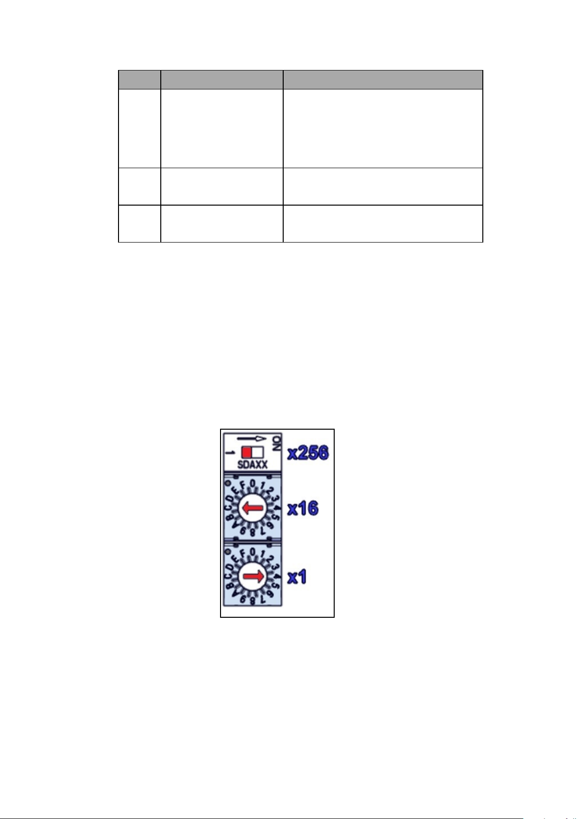
Item Switch Description
A 2-Position Dip Switch
x256
Sets the 8th (most significant bit) of the 9-bit
EtherCAT node ID.
Moving the switch to the right turns ON the
8th bit for the node ID.
The default position is OFF(left).
16-Position Rotary Switch
B
x16
16-Position Rotary Switchx1Sets bits 3 to 0 of the EtherCATnode ID.
C
Sets bits 7 to 4 of the EtherCATnodeID.
The default setting for this switch is 0.
The default setting for this switch is 0.
EtherCAT Node ID Address Example
Use the following example to understand how to set the EtherCATnode ID. An EtherCAT
nodeID of 196 is used in this example.
1.
Convert the node IDof 196 into hexadecimal format (0x0C4).
2. Set the x256 dip switch to OFF.
3.
Set the x16 rotary switch to C.
4. Set the x1 rotary switch to 4.
NOTE: Use Sysmac Studio to verify the EtherCATnode IDsetting. Refer to Sys-
mac Studio Version 1 Operation Manual (Cat. No. W504) for more information.
Figure 3-10. EtherCATNode IDSet to 196
60 eCobra 600 and 800 Robots with EtherCAT 24402-000 Rev B
Page 61
Chapter 4: System Cable Installation
!
This chapter provides details about system cable installation.
This chapter assumes that you have already installed the robot and mounted a Front Panel.
WARNING: ELECTROCUTION RISK.
Dangerous voltages are present during cable installation, and you must take
appropriate lockout / tagout measures to prevent powering up the robot during
installation.
WARNING: ELECTROCUTIONRISK
National Electrical Code (and/or local codes) require that you provide an appropriately sized Branch Circuit Protection and lockout / tagout capability. Ensure
that you comply with all local and national safety and electrical codes for the
installation and operation of the robot system.
WARNING: ELECTROCUTIONRISK
eCobra robot systems require an isolating transformer for connection to asymmetrical mains systems or those using an isolated (impedant) neutral. Many
parts of Europe use an impedant neutral.
DANGER: ELECTROCUTIONRISK
Only a skilled and instructed person must install ACpower. Clause 5.2.4 of the
ISO 10218-1 requires that the person installing the system must use fail-safe
lockout measures to prevent unauthorized third parties from turning on power.
Refer to the Robot Safety Guide (Cat. No. I590)for more information.
CAUTION: Ensure that all cables are installed with strain-relief to ensure they
are not damaged or accidentally removed during operation.
4.1 Basic System Cable Layout
The following diagram illustrates typical cable connections for a robot system.
The letters in the following figure correspond to the letters in the List of Cables and Parts on
page 62..
The numbers in the following figure correspond to the Cable Installation Steps on page 64.
NOTE: The figure below includes the optional and user-supplied equipment
that may not be present in your system.
Additional Information: Ethernet / EtherCAT network connections may differ for
your application. Contact your local OMRON support for more information.
24402-000 Rev B eCobra 600 and 800 Robots with EtherCAT 61
Page 62

Figure 4-1. Typical System Cable Connections
List of Cables and Parts
The following table identifies and provides details about cables and parts illustrated in Basic
System Cable Layout on page 61.
62 eCobra 600 and 800 Robots with EtherCAT 24402-000 Rev B
Page 63

Chapter 4: System Cable Installation
!
NOTE: The XUSR, XMCP, and XFP jumpers intentionally bypass safety connections so you can test the system functionality during setup.
WARNING: PERSONALINJURYRISK
Never run a robot system, in automatic mode, with all three jumpers installed.
This would leave the system with no E-Stops.
Part Cable and Parts List Part # Standard Option User
Supplied
A iCS-ECAT Robot Interface Panel X
B EtherCAT cable X
C EtherCATcable connection to
other EtherCAT peripherals (servos, vision systems, etc.)
D NJ-series Robot Integrated CPU NJ501-RXXX X
E Ethernet/IP cable X
F Network switch X
G User-supplied PC X
H Ethernet/IP cable
I Ethernet RJ45 Port X
J Ethernet/IP cable to IPC Applic-
ation Controller
K IPC Application Controller
L Power over Ethernet (PoE) cable
to Camera
M XBELTIO Cable 13463-000
1
X
X
X
X
X
X
N XIO Breakout Cable 03695-000
200-240 VAC AC Power Cable 04118-000 X
P
24 VDC Power Cable 04120-000 X
Q
Cable Assembly, XSYSTEM
R
Adapter with Jumpers
S XFP Connector on XSYSTEM
cable
XFP Jumper Plug
T
Front Panel
U
24402-000 Rev B eCobra 600 and 800 Robots with EtherCAT 63
4
2
3
13322-100
10052-000
90356-10358
X
X
X
X
X
X
X
Page 64

Part Cable and Parts List Part # Standard Option User
Supplied
V XUSRConnector on XSYSTEM
X
cable
XUSR Jumper Plug
W
X XMCP Connector on XSYSTEM
5
04736-000
X
X
cable
XMCP Jumper Plug
Y
T20 Pendant 10054-010 X
Z
6
10052-000
X
NOTES:
1
A USBcable can be used as a direct connection between thePC and the NJ-series Robot
Integrated CPU Unit.
2
This assembly also includes the XFP Jumper Plug, XMCP Jumper Plug, and the XUSR
Jumper Plug.
3
Required if not using a Front Panel.
4
Requires Front Panel Cable (part number 10356-10500).
5
Required if not using user-supplied E-Stop circuitry.
6
Required if not using a pendant.
Cable Installation Steps
Use the following procedure to install all necessary system cables. Refer to Basic System Cable
Layout on page 61 for references to item letters.
Additional Information: Refer to iCS-ECAT Robot Interface Panel on page 24 for
robot interface panel connector details.
Step Connection Item
1 Connect the XSYSTEM cable to the XSYSTEM connector on the robot
interface panel.
2 Connect a user E-Stop or Muted Safety Gate to the XSYSTEM cable XUSR
connector or verify XUSR jumper plug is installed in XSYSTEM cable
XUSR connector.
3 Connect the Front Panel cable to Front Panel and XSYSTEM cable XFP
connector.
If no Front Panelis present in the system, install FP jumper on XSYSTEM
cable XFP connector.
4 Connect T20 adapter cable (not shown) to XSYSTEM cable XMCP con-
nector.
If no T20 is present in the system, install XMCP jumper, or T20 Adapter
Cable with bypass plug.
R, A
W, V
S, U
T
X
Y
64 eCobra 600 and 800 Robots with EtherCAT 24402-000 Rev B
Page 65

Chapter 4: System Cable Installation
Step Connection Item
5 Connect a 24 VDC cable to the DC power supply connector on the robot
interface panel.
Connect user-supplied ground to the robot. Refer to See Grounding the
6
Robot System on page 84 for more information.
NOTE: The ground may be part of the 24 VDC cable.
7 Connect a 200-240 VAC cable to the AC power supply connector on
Robot Interface Panel and secure with clamp.
Connect user-supplied communication / network cables to their respect-
8
ive devices.
Additional Information: Ethernet / EtherCAT network connections may differ. Contact your local OMRON support
for more information.
XBELT IO Belt Encoder Y Adapter Cable
The XBELT IO Encoder Y Adapter Cable adds two additional encoder outputs (for ENC1 and
ENC2, to the Belt Branch.
Q
P
B, C, D,
E, F, G,
H, J, K,
L
Figure 4-2. System Cable Diagram with Belt Encoders (Units in mm)
Table 4-1. Belt Encoder Cables Description
Item
A Robot Interface
B XBELT IO
C Belt Branch Con-
Description
Panel
Adapter Cable
Connector
nector
Part # Standard Option
X
13463-000 X X HDB26
User-
supplied
Notes
Female
DB15
Male
24402-000 Rev B eCobra 600 and 800 Robots with EtherCAT 65
Page 66

Item
Description
Part # Standard Option
User-
supplied
Notes
D EXPIO Branch
Connector
E RS-232 Branch
Connector
F Belt Y Splitter
Cable Connector
G Belt Encoder 1
Connector
H Belt Encoder 2
Connector
Pinouts for XBELT IO Adapter
09443-000 X X DB15
NOTE: In the following figures, the callout letters (circled in red) correspond to
the Item letters in XBELT IO Belt Encoder Y Adapter Cable on page 65.
Belt Encoder
DB9 Male
DB9 Male
Female
M12
Female,
8 pin
M12
Female,
8-pin
Figure 4-3. XBELT I/O Adapter Cable Pinout - Encoder 1 and 2 Connections
RS-232
66 eCobra 600 and 800 Robots with EtherCAT 24402-000 Rev B
Page 67

Figure 4-4. XBELTI/O Adapter Cable Pinout - RS-232 Connections
FORCE / EXPIO
Figure 4-5. XBELT I/O Adapter Cable Pinout - EXPIO Connections
Splitter Cable
Chapter 4: System Cable Installation
Figure 4-6. Belt Y Splitter Cable Pinout - 2 Encoder Connections
4.2 Connecting Digital I/O to the System
Use the table below to understand the different digital I/O connection methods.
Table 4-2. Digital I/O Connection Options
Connection I/O Capacity Additional Information
XIO Connector on the
robot interface panel
Optional IO Blox Device,
connects to the RS232
connector on the back of
24402-000 Rev B eCobra 600 and 800 Robots with EtherCAT 67
12 inputs
8 outputs
8 inputs, 8 outputs per device;
up to 4 IO Blox devices for the
Standard eCobra, up to 8 IO Blox
Refer to XIO Connector Signals on page 76
Refer to the IO Blox User’s
Guide (04638-000)
Page 68

Connection I/O Capacity Additional Information
the robot's Joint 1.
devices for the eCobra Pro
2nd group of IO Blox connect to FORCE/EXPIO
branch of the XBELTIO
cable.
Optional XIO
Termination Block,
12 inputs
8 outputs
Refer to Digital I/O Signal
Configuration on page 68
connects to iCS-ECAT
robot interface panel
Digital I/O Signal Configuration
This section provides information about digital I/Osignal configuration..
NOTE: The eCobra Standard can only support a maximum of 4 daisy-chained
IOBlox devices.
IO Blox Connections
When installing more than one IO Blox unit in a system, you must connect the units with the
supplied cable(s) and set the address select switch correctly for each additional unit.
NOTE: Each IO Blox unit (up to 4 for Standard, 8 for Pro) must have a unique
address. IO Blox units with duplicate addresses will conflict. Refer to the IO Blox
User’s Guide (04638-000)for more information.
Figure 4-7. Connecting IO Blox to the system (maximum of 4 for Standard, 8 for Pro)
68 eCobra 600 and 800 Robots with EtherCAT 24402-000 Rev B
Page 69
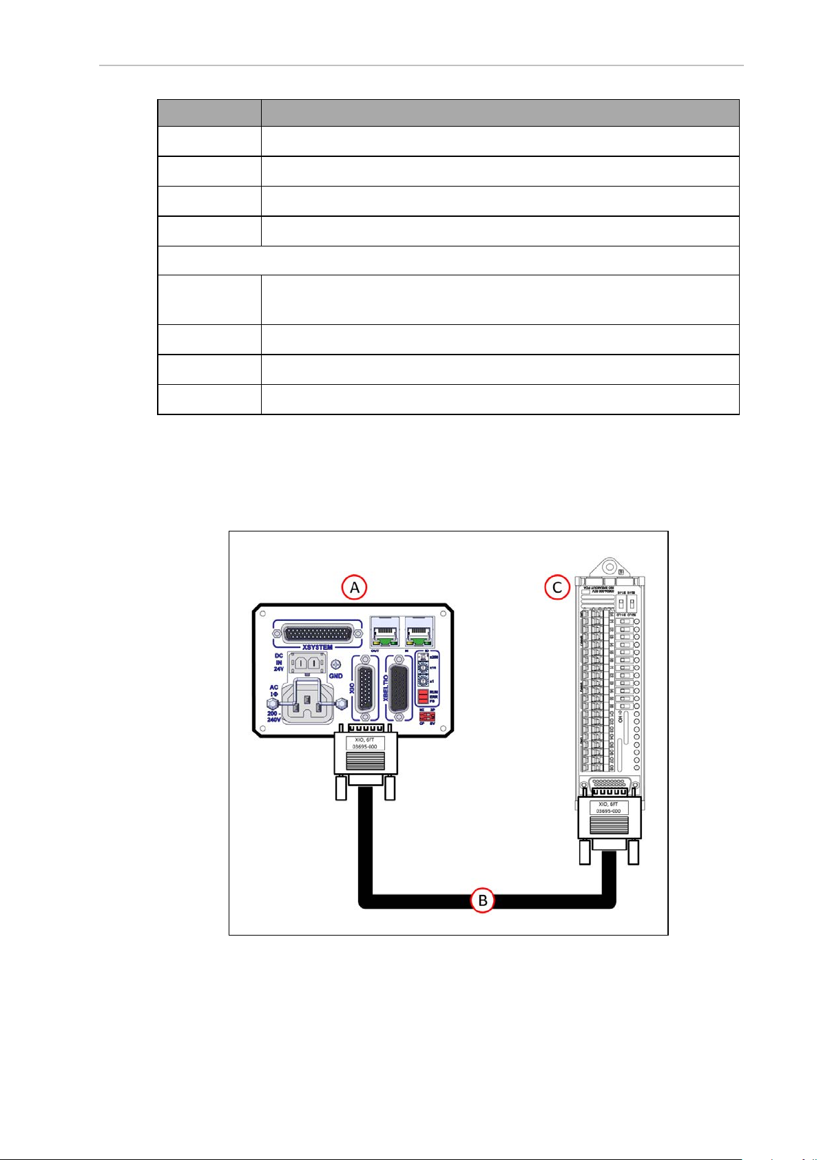
Chapter 4: System Cable Installation
Item Description
A
B
C
D
The following cables and connections apply to the eCobra Pro only.
E
eCobra Robot user connections on the back of Joint 1 (viewed from the rear)
IO Blox-to-Robot cable (3 m) P/N 04677-030
IO Blox-to-IO Blox Cable (3 m) P/N 04679-03
IO Blox Group 1 (eCobra Standard and Pro), maximum 4 IO Blox units
XBELTIO Cable P/N 13463-000 connected to XBELTIO connector on the
robot interface panel
F
G
H
XIO Termination Block
FORCE/EXPIO Connector on XBELTIO cable
IO Blox-to-Robot cable (3 m), part number 04677-030
IO Blox Group 2 (eCobra Pro only), maximum 4 IO Blox units
You can also expand digital I/O by connecting an XIO Termination Block to the XIO connector
on the robot interface panel. The XIO Termination Block provides 12 inputs and 8 outputs
(refer to the following figure). This offers the same signal capacity as the XIO connector on the
robot interface panel.
Figure 4-8. Connecting XIO Termination Block
24402-000 Rev B eCobra 600 and 800 Robots with EtherCAT 69
Page 70

Callout Function
A
B
C
Robot Interface Panel
XIO Termination Cable, part number 03695-000
XIO Termination Block, part number 90356-40100
NOTE: The supplied XIO Termination cable is 2m long and made using shielded 26 AWG wire(wired 1:1). You can construct your own extended length
cables using similar cable stock. Give careful attention to voltage drops on the
I/O outputs when using extended length cables and high current loads.
Default Signal Allocations
The digital I/O for the eV+ programming language uses numeric signal numbers, with possible
outputs, inputs, software signals, robot signals and external signals in the ranges below.
NOTE: Each IOBlox group has a maximum of 4 IOBlox units, daisy-chained for
a range of 32 signals (4 units x 8 inputs/outputs).
Default Input SignalAllocations
Use the table below to understand default input allocations.
Table 4-3. Default Input Signal Allocations
Robot Connector Channel
1 XIO XIO N/A Inputs on the
EXPIO IOBlox
Group 1
XBELTIO IOBlox
Group 2
Switch Position
(1, 2)
OFF, OFF Inputs on IOBlox11033 to
ON, OFF Inputs on IOBlox21041 to
OFF, ON Inputs on IOBlox31049 to
ON, ON Inputs on IOBlox41057 to
OFF, OFF Inputs on IOBlox51065 to
ON, OFF Inputs on IOBlox61073 to
OFF, ON Inputs on IOBlox71081 to
ON, ON Inputs on IOBlox81089 to
Type
iCS-ECAT
Signal
Number
1001 to
1012
1040
1048
1056
1064
1072
1080
1088
1096
2 XIO XIO N/A Inputs on the
iCS-ECAT
1097 to
1108
70 eCobra 600 and 800 Robots with EtherCAT 24402-000 Rev B
Page 71

Chapter 4: System Cable Installation
Robot Connector Channel
EXPIO IOBlox
Group 1
XBELTIO IOBlox
Group 2
3 XIO XIO N/A Inputs on the
Switch Position
(1, 2)
OFF, OFF Inputs on IOBlox11129 to
ON, OFF Inputs on IOBlox21137 to
OFF, ON Inputs on IOBlox31145 to
ON, ON Inputs on IOBlox41153 to
OFF, OFF Inputs on IOBlox51161 to
ON, OFF Inputs on IOBlox61169 to
OFF, ON Inputs on IOBlox71177 to
ON, ON Inputs on IOBlox81185 to
Type
iCS-ECAT
Signal
Number
1136
1144
1152
1160
1168
1176
1184
1192
1193 to
1204
EXPIO IOBlox
Group 1
XBELTIO IOBlox
Group 2
4 XIO XIO N/A Inputs on the
EXPIO IOBlox
Group 1
OFF, OFF Inputs on IOBlox11225 to
ON, OFF Inputs on IOBlox21233 to
OFF, ON Inputs on IOBlox31241 to
ON, ON Inputs on IOBlox41249 to
OFF, OFF Inputs on IOBlox51257 to
ON, OFF Inputs on IOBlox61265 to
OFF, ON Inputs on IOBlox71273 to
ON, ON Inputs on IOBlox81281 to
iCS-ECAT
OFF, OFF Inputs on IOBlox11321 to
1232
1240
1248
1256
1264
1272
1280
1288
1289 to
1300
1328
ON, OFF Inputs on IOBlox21329 to
1336
24402-000 Rev B eCobra 600 and 800 Robots with EtherCAT 71
Page 72

Robot Connector Channel
Switch Position
(1, 2)
OFF, ON Inputs on IOBlox31337 to
ON, ON Inputs on IOBlox41345 to
Type
Signal
Number
1344
1352
XBELTIO IOBlox
Group 2
5 XIO XIO N/A Inputs on the
EXPIO IOBlox
Group 1
XBELTIO IOBlox
Group 2
OFF, OFF Inputs on IOBlox51353 to
ON, OFF Inputs on IOBlox61361 to
OFF, ON Inputs on IOBlox71369 to
ON, ON Inputs on IOBlox81377 to
iCS-ECAT
OFF, OFF Inputs on IOBlox11417 to
ON, OFF Inputs on IOBlox21425 to
OFF, ON Inputs on IOBlox31433 to
ON, ON Inputs on IOBlox41441 to
OFF, OFF Inputs on IOBlox51449 to
1360
1368
1376
1384
1385 to
1396
1424
1432
1440
1448
1456
ON, OFF Inputs on IOBlox61457 to
OFF, ON Inputs on IOBlox71465 to
ON, ON Inputs on IOBlox81473 to
6 XIO XIO N/A Inputs on the
iCS-ECAT
EXPIO IOBlox
Group 1
OFF, OFF Inputs on IOBlox11513 to
ON, OFF Inputs on IOBlox21521 to
OFF, ON Inputs on IOBlox31529 to
ON, ON Inputs on IOBlox41537 to
1464
1472
1480
1481 to
1492
1520
1528
1536
1544
72 eCobra 600 and 800 Robots with EtherCAT 24402-000 Rev B
Page 73

Chapter 4: System Cable Installation
Robot Connector Channel
XBELTIO IOBlox
Group 2
7 XIO XIO N/A Inputs on the
EXPIO IOBlox
Group 1
Switch Position
(1, 2)
OFF, OFF Inputs on IOBlox51545 to
ON, OFF Inputs on IOBlox61553 to
OFF, ON Inputs on IOBlox71561 to
ON, ON Inputs on IOBlox81569 to
OFF, OFF Inputs on IOBlox11609 to
ON, OFF Inputs on IOBlox21617 to
OFF, ON Inputs on IOBlox31625 to
ON, ON Inputs on IOBlox41633 to
Type
iCS-ECAT
Signal
Number
1552
1560
1568
1576
1577 to
1588
1616
1624
1632
1640
XBELTIO IOBlox
Group 2
8 XIO XIO N/A Inputs on the
EXPIO IOBlox
Group 1
XBELTIO IOBlox
Group 2
OFF, OFF Inputs on IOBlox51641 to
ON, OFF Inputs on IOBlox61649 to
OFF, ON Inputs on IOBlox71657 to
ON, ON Inputs on IOBlox81665 to
iCS-ECAT
OFF, OFF Inputs on IOBlox11705 to
ON, OFF Inputs on IOBlox21713 to
OFF, ON Inputs on IOBlox31721 to
ON, ON Inputs on IOBlox41729 to
OFF, OFF Inputs on IOBlox51737 to
1648
1656
1664
1672
1673 to
1684
1712
1720
1728
1736
1744
ON, OFF Inputs on IOBlox61745 to
1752
24402-000 Rev B eCobra 600 and 800 Robots with EtherCAT 73
Page 74
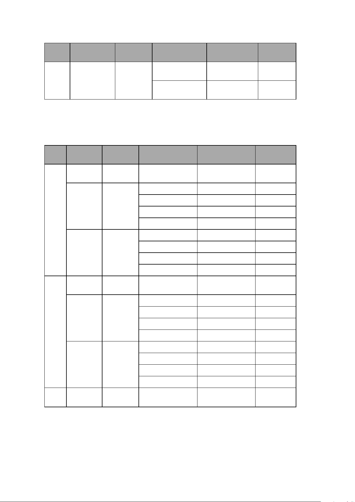
Robot Connector Channel
DefaultOutput Signal Allocations
Switch Position
(1, 2)
OFF, ON Inputs on IOBlox71753 to
ON, ON Inputs on IOBlox81761 to
Use the table below to understand default output allocations.
Table 4-4. Default Output Signal Allocations
Type
Signal
Number
1760
1768
Robot Connector Channel
1 XIO XIO N/A Outputs on the iCS-
EXPIO IOBlox
Group 1
XBELTIO IOBlox
Group 2
2 XIO XIO N/A Outputs on the iCS-
EXPIO IOBlox
Group 1
Switch Position
(1, 2)
ECAT
OFF, OFF Outputs on IOBlox 1 33 to 40
ON, OFF Outputs on IOBlox 2 41 to 48
OFF, ON Outputs on IOBlox 3 49 to 56
ON, ON Outputs on IOBlox 4 57 to 64
OFF, OFF Outputs on IOBlox 5 65 to 72
ON, OFF Outputs on IOBlox 6 73 to 80
OFF, ON Outputs on IOBlox 7 81 to 88
ON, ON Outputs on IOBlox 8 89 to 96
ECAT
OFF, OFF Outputs on IOBlox 1 129 to 136
ON, OFF Outputs on IOBlox 2 137 to 144
OFF, ON Outputs on IOBlox 3 145 to 152
Type
Signal
Number
1 to 8
97 to 104
ON, ON Outputs on IOBlox 4 153 to 160
XBELTIO IOBlox
Group 2
3 XIO XIO N/A Outputs on the iCS-
OFF, OFF Outputs on IOBlox 5 161 to 168
ON, OFF Outputs on IOBlox 6 169 to 176
OFF, ON Outputs on IOBlox 7 177 to 184
ON, ON Outputs on IOBlox 8 185 to 192
193 to 200
ECAT
74 eCobra 600 and 800 Robots with EtherCAT 24402-000 Rev B
Page 75
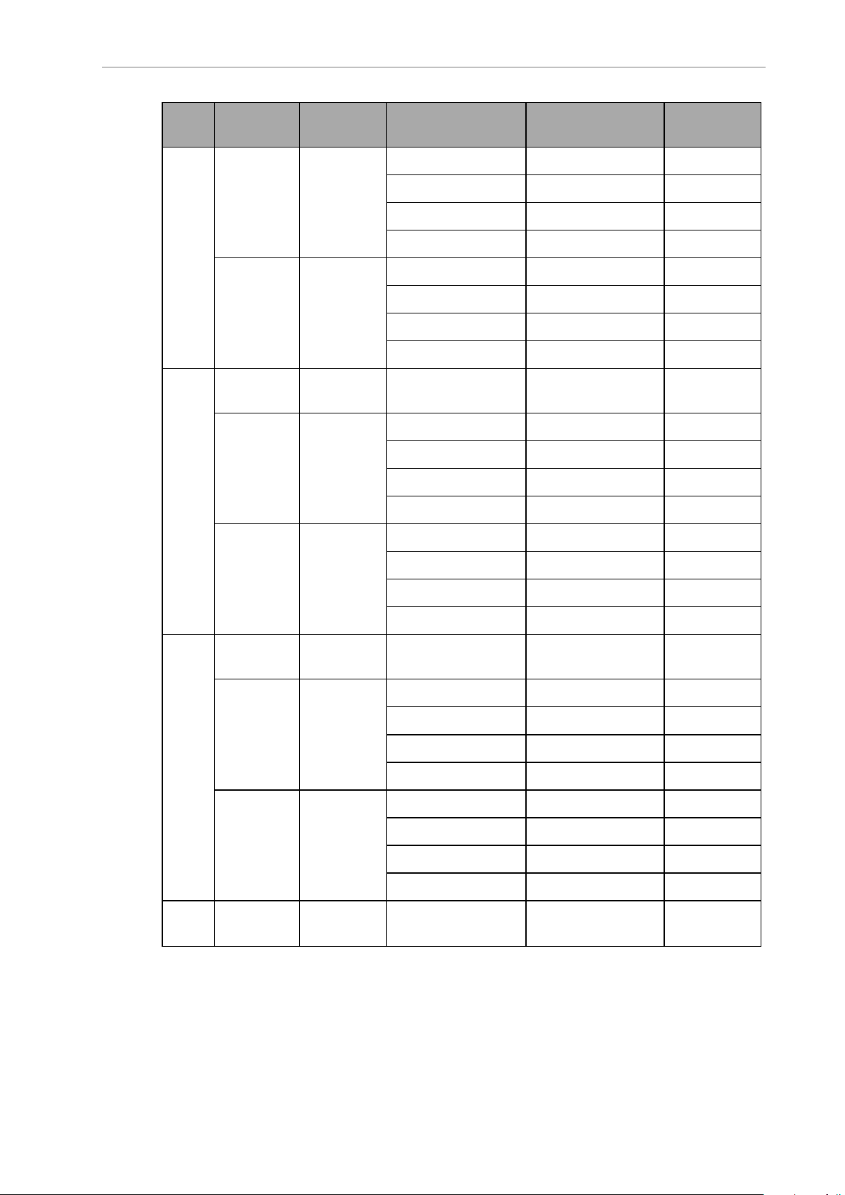
Chapter 4: System Cable Installation
Robot Connector Channel
EXPIO IOBlox
Group 1
XBELTIO IOBlox
Group 2
4 XIO XIO N/A Outputs on the iCS-
EXPIO IOBlox
Group 1
Switch Position
(1, 2)
OFF, OFF Outputs on IOBlox 1 225 to 232
ON, OFF Outputs on IOBlox 2 233 to 240
OFF, ON Outputs on IOBlox 3 241 to 248
ON, ON Outputs on IOBlox 4 249 to 256
OFF, OFF Outputs on IOBlox 5 257 to 264
ON, OFF Outputs on IOBlox 6 265 to 272
OFF, ON Outputs on IOBlox 7 273 to 280
ON, ON Outputs on IOBlox 8 281 to 288
ECAT
OFF, OFF Outputs on IOBlox 1 321 to 328
ON, OFF Outputs on IOBlox 2 329 to 336
OFF, ON Outputs on IOBlox 3 337 to 344
ON, ON Outputs on IOBlox 4 345 to 352
Type
Signal
Number
289 to 296
XBELTIO IOBlox
Group 2
5 XIO XIO N/A Outputs on the iCS-
EXPIO IOBlox
Group 1
XBELTIO IOBlox
Group 2
6 XIO XIO N/A Outputs on the iCS-
OFF, OFF Outputs on IOBlox 5 353 to 360
ON, OFF Outputs on IOBlox 6 361 to 368
OFF, ON Outputs on IOBlox 7 369 to 376
ON, ON Outputs on IOBlox 8 377 to 384
ECAT
OFF, OFF Outputs on IOBlox 1 417 to 424
ON, OFF Outputs on IOBlox 2 425 to 432
OFF, ON Outputs on IOBlox 3 433 to 440
ON, ON Outputs on IOBlox 4 441 to 448
OFF, OFF Outputs on IOBlox 5 449 to 456
ON, OFF Outputs on IOBlox 6 457 to 464
OFF, ON Outputs on IOBlox 7 465 to 472
ON, ON Outputs on IOBlox 8 473 to 480
ECAT
385 to 392
481 to 488
24402-000 Rev B eCobra 600 and 800 Robots with EtherCAT 75
Page 76

Robot Connector Channel
Switch Position
(1, 2)
Type
Signal
Number
EXPIO IOBlox
Group 1
OFF, OFF Outputs on IOBlox 1 513 to 520
ON, OFF Outputs on IOBlox 2 521 to 528
OFF, ON Outputs on IOBlox 3 529 to 536
ON, ON Outputs on IOBlox 4 537 to 544
XBELTIO IOBlox
Group 2
OFF, OFF Outputs on IOBlox 5 545 to 552
ON, OFF Outputs on IOBlox 6 553 to 560
OFF, ON Outputs on IOBlox 7 561 to 568
ON, ON Outputs on IOBlox 8 569 to 576
7 XIO XIO N/A Outputs on the iCS-
ECAT
EXPIO IOBlox
Group 1
OFF, OFF Outputs on IOBlox 1 609 to 616
ON, OFF Outputs on IOBlox 2 617 to 624
OFF, ON Outputs on IOBlox 3 625 to 632
ON, ON Outputs on IOBlox 4 633 to 640
XBELTIO IOBlox
Group 2
OFF, OFF Outputs on IOBlox 5 641 to 648
ON, OFF Outputs on IOBlox 6 649 to 656
577 to 584
OFF, ON Outputs on IOBlox 7 657 to 664
ON, ON Outputs on IOBlox 8 665 to 672
8 XIO XIO N/A Outputs on the iCS-
673 to 680
ECAT
EXPIO IOBlox
Group 1
OFF, OFF Outputs on IOBlox 1 705 to 712
ON, OFF Outputs on IOBlox 2 713 to 720
OFF, ON Outputs on IOBlox 3 721 to 728
ON, ON Outputs on IOBlox 4 729 to 736
XBELTIO IOBlox
Group 2
OFF, OFF Outputs on IOBlox 5 737 to 744
ON, OFF Outputs on IOBlox 6 745 to 752
OFF, ON Outputs on IOBlox 7 753 to 760
ON, ON Outputs on IOBlox 8 761 to 768
XIO Connector Signals
The XIO connector on the robot interface panel offers access to digital I/O (12 inputs and 8 outputs). Refer to the following table for the XIO signal designations.
l
12 Inputs, signals 1097 to 1108
l
8 Outputs, signals 0097 to 0104
76 eCobra 600 and 800 Robots with EtherCAT 24402-000 Rev B
Page 77
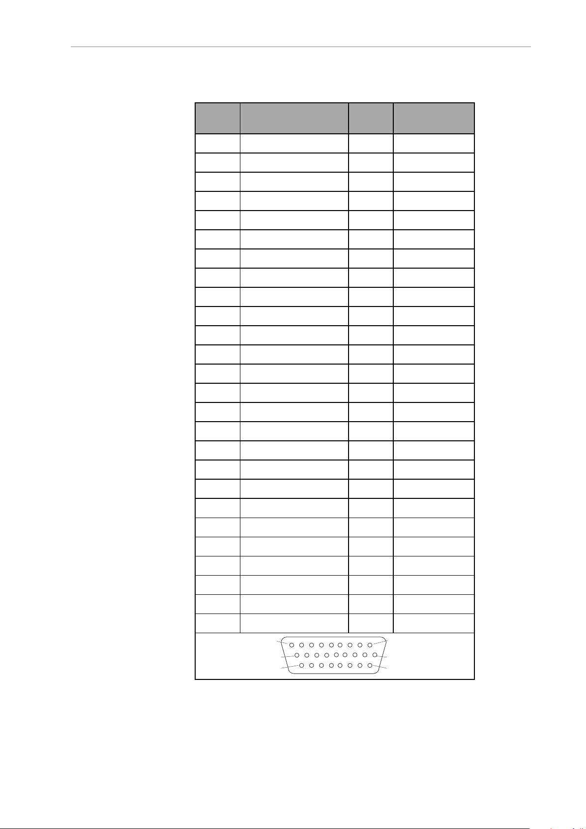
Chapter 4: System Cable Installation
Pin 1Pin 9
Pin 10
Pin 18
Pin 26
Pin 19
Table 4-5. XIO Signal Designations
Pin No. Designation
Signal
Bank
eV+ Signal
1 GND
2 24 VDC
3 Common 1 1
4 Input 1.1 1 1097
5 Input 2.1 1 1098
6 Input 3.1 1 1099
7 Input 4.1 1 1100
8 Input 5.1 1 1101
9 Input 6.1 1 1102
10 GND
11 24 VDC
12 Common 2 2
13 Input 1.2 2 1103
14 Input 2.2 2 1104
Number
15 Input 3.2 2 1105
16 Input 4.2 2 1106
17 Input 5.2 2 1107
18 Input 6.2 2 1108
19 Output 1 0097
20 Output 2 0098
21 Output 3 0099
22 Output 4 0100
23 Output 5 0101
24 Output 6 0102
25 Output 7 0103
26 Output 8 0104
24402-000 Rev B eCobra 600 and 800 Robots with EtherCAT 77
Page 78

XIO Input Signals
The 12 input channels are arranged in two banks of six. Each bank is electrically isolated from
the other bank and is optically isolated from the robot’s ground. The six inputs within each
bank share a common source and/or sink line.
The inputs are accessed through direct connection to the XIO connector (see the previous
table), or through the optional XIO Termination Block. See the documentation supplied with
the termination block for details.
XIO Output Signals
The eight digital outputs share a common, high side (sourcing) driver integrated circuit. The
driver is designed to supply any kind of load with one side connected to ground. It is designed
for a range of user-provided voltages from 10 to 24 VDC and each channel is capable of
switching up to 0.7 A of current. This driver has overtemperature protection, shorted load protection, and is current limiting. If there is an output short or other overcurrent situation, the
affected output of the driver integrated circuit turns OFF and back ON automatically to reduce
the internal temperature. The driver draws power from the primary 24 VDC input to the robot
through a self-resetting polyfuse.
The outputs are accessed through direct connection to the XIO connector. Optionally, use the
XIO Termination Block. See the documentation supplied with the termination block for details.
High Power Indicator Output Assignment
Output 8 can be assigned to indicate the robot's high power state. When high power is
enabled, this output will turn ON. When high power is not enabled, this output will be OFF.
Use Sysmac Studio to make this configuration if needed.
4.3 Connecting the 24 VDC Cable to the Robot
Power requirements for the user-supplied power supply vary depending on the configuration
of the robot and connected devices. OMRON recommends a 24 VDC, 6 A power supply to
allow for startup current draw from connected user devices, such as solenoids and digital I/O
loads.
Additional Information: Refer to External Connection Specifications on page
145for more information about 24VDCpower requirements.
24 VDC Power Supply Connector
The cable and accessory box that came with your system contains the 24 VDC power supply
connector and two pins. Use the following figure to determine the pin arrangement.
Additional Information: Refer to ConnectorSpecifications on page 148 for more
information.
Figure 4-9. 24 VDCMating Connector Pin Arrangement
78 eCobra 600 and 800 Robots with EtherCAT 24402-000 Rev B
Page 79

Chapter 4: System Cable Installation
Making the 24 VDC Power Supply Cable
Use the following procedure to make a 24 VDCcable.
Additional Information: The 24 VDC cable is not supplied with the system, but
is available in the optional Power Cable kit (part number 04120-000) Refer to
Basic System Cable Layout on page 61for more information. See Figure 4-11.
1.
Locate the connector and pins.
2.
Use 2.08-1.31 mm2(14-16 AWG) wire to create the 24 VDC cable. Select the wire length
to safely reach from the user-supplied 24 VDC power supply to the robot interface
panel.
3.
Crimp the pins to the wires using a crimping tool.
4.
Insert the pins into the connector. Confirm that the 24 VDC and 24 VDC return wires
are in the correct terminals in the plug.
Connecting the 24 VDC Cable
Use the following procedure to connect the 24 VDC cable from the power supply to the robot
interface panel.
Additional Information: Refer to External Connection Specifications on page 145
for more information.
IMPORTANT: Do not apply 24 VDC power until all installation steps are complete and verified and all safety measures are in place.
The following instructions correspond to the numbered steps in green boxes in the following
figure. The red circled letters identify specific items.
24402-000 Rev B eCobra 600 and 800 Robots with EtherCAT 79
Page 80

Figure 4-10. User-Supplied 24 VDC Cable, Power Supply
!
Item Description
A Robot interface panel
B User-supplied 24 VDC power supply
C Power Supply frame ground
D 8 A (max) in-line circuit protection
E User-supplied 24 VDC (14-16 AWG) Shielded Cable
F Molex Saber 18 A, 2-pin Connector
G Ground screw on robot interface panel
NOTE: To comply with standards, DC power should be supplied over a shielded cable with the shield connected to frame ground at both ends of the cable.
1.
Connect one end of the shielded 24 VDC cable (E)to the 24 VDC power supply (B)
observing the correct polarity.
CAUTION: PROPERTYDAMAGERISK
The 24 VDCoutput must be less than 300 W peak or 8 Amp (max) inline circuit protection must be provided for each connected robot. Refer
to (D) in Figure 4-10. .
80 eCobra 600 and 800 Robots with EtherCAT 24402-000 Rev B
Page 81

Chapter 4: System Cable Installation
2.
Connect the cable shield (D) to frame ground on the power supply (C).
3.
Plug the mating connector end of the 24 VDC cable (F) into the 24 VDC connector on
the robot interface panel(A).
4. Connect the cable shield (G) to the ground point on the robot interface panel (A).
4.4 Connecting 200-240 VAC Power Cable
Use the following procedure to connect the 200-240 VAC cable from the power supply to the
robot interface panel.
Additional Information: Refer to External Connection Specifications on page 145
for more information.
IMPORTANT: Do not apply AC power until all installation steps are complete
and verified and all safety measures are in place.
WARNING: ELECTROCUTIONRISK
National Electrical Code (and/or local codes) require that you provide an appropriately sized branch circuit protection and lockout/tagout capability. Ensure
you comply with all local and national safety and electrical codes for the
installation and operation of the robot system.
DANGER: ELECTROCUTIONRISK
ISO 10218-1, Clause 5.2.4 mandates that, during installation, you must provide
a fail-safe lockout to prevent unauthorized third parties from turning on power.
WARNING: ELECTROCUTIONRISK
eCobra robot systems require an isolating transformer for connection to asymmetrical mains systems or those using an isolated (impedant) neutral. Many
parts of Europe use an impedant neutral.
DANGER: ELECTROCUTIONRISK
Only a skilled and instructed person must install ACpower. Clause 5.2.4 of the
ISO 10218-1 requires that the person installing the system must use fail-safe
lockout measures to prevent unauthorized third parties from turning on power.
Refer to the Robot Safety Guide (Cat. No. I590) for more information.
NOTE: Install the robot system as a piece of equipment in a permanentlyinstalled system.
AC Power Diagrams
If using a three-phase power source, it must be symmetrically-earthed (with grounded neutral).
Connections called out as single-phase can be wired Line-to-Neutral or Line-to-Line.
24402-000 Rev B eCobra 600 and 800 Robots with EtherCAT 81
Page 82

Figure 4-11. Typical AC Power Installation with Single-Phase Supply
Key Meaning
A Robot 1Ø 200-240 VAC
B User-supplied AC power cable
C F1 - 10A
D NOTE: F1 is user-supplied, and must be slow-blow
E L=Line
F N=Neutral
G E=Earth Ground
Figure 4-12. Single-Phase Load across L1 and L2 of a Three-Phase Supply
82 eCobra 600 and 800 Robots with EtherCAT 24402-000 Rev B
Page 83

Chapter 4: System Cable Installation
Key Meaning
A Robot 1Ø 200-240 VAC
B User-supplied AC power cable
C 200-240 VAC
Fuses F4 and F5
D
NOTE: These fuses must be slow-blow
E L=Line 1
F N=Line 2
G L3=Line 3 (not used)
H E= Earth Ground
AC Power Supply Connector
The cable and accessory box that came with your system contains the AC power supply connector. The supplied plug is internally labeled for the AC power connections (L, E, N).
Additional Information: Refer to ConnectorSpecifications on page 148 for more
information.
Figure 4-13. ACPowerSupply Connector
Making the 200-240 VAC Power Supply Cable
Use the following procedure to make the 200-240 VACpower supply cable.
Before you begin, you will need 3-wire, 0.8 mm2(18 AWG) cable long enough to reach from
the AC power source to the robot.
1.
Locate the AC power supply connector.
2.
Unscrew the shell screw, open the connector, and remove the cover.
3.
Loosen the two screws on the cable clamp.
4.
Strip approximately 18 to 24 mm of insulation from each of the three wires.
5.
Insert the wires into the connector through the removable bushing.
6.
Connect each wire to the correct terminal screw and tighten the screw firmly.
7.
Tighten the screws on the cable clamp, then reinstall the cover and tighten the screw.
8.
Prepare the opposite end of the cable for connection to the facility AC power source.
24402-000 Rev B eCobra 600 and 800 Robots with EtherCAT 83
Page 84

Figure 4-14. AC Power Mating Connector
Key Meaning Key Meaning
A Removable Bushing D Neutral
B Cable Clamp E Earth
C Line
Connecting the AC Power Supply Cable
Use the following procedure to connect the ACpower supply cable from the power source to
the robot interface panel.
Additional Information: Refer to External Connection Specifications on page 145
for more information.
IMPORTANT: Do not apply AC power until all installation steps are complete
and verified and all safety measures are in place.
1.
With the ACsupply OFF, connect the unterminated end of the AC power cable to your
facility AC power source.
2.
Plug the AC connector into the AC power connector on the robot interface panel on the
robot.
3.
Secure the AC connector with the locking latch.
4.5 Grounding the Robot System
Proper grounding is essential for safe and reliable robot operation. Follow these recommendations to properly ground your robot.
84 eCobra 600 and 800 Robots with EtherCAT 24402-000 Rev B
Page 85

Chapter 4: System Cable Installation
Grounding the Robot Base
You can ground the robot base by using a ground wire at the robot base (see the following figure). The robot ships with an M8 x 12 stainless steel, hex-head screw, and M8 split and flat
washers installed in the grounding hole. You must supply the ground wire.
Figure 4-15. Ground Point on Robot Base
IMPORTANT: The earth ground conductor resistance must be ≤ 10 Ω.
Callout Description
A Ground point location on robot base
B Ground lug
C Ground label
Grounding Robot-Mounted Equipment
The Joint 3 quill and the tool flange are not grounded to protective earth. If hazardous voltages
are present at any user-supplied robot-mounted equipment or tooling, you must install a
ground connection from that equipment or tooling to the ground point on the robot base. Hazardous voltages are anything over 30 VAC (42.4 VAC peak) or 60VDC.
Additional Information: Refer to Tool Flange Dimensions on page 149 for more
information about the tool flange grounding point.
DANGER: ELECTROCUTION HAZARD
Failing to ground robot-mounted equipment or tooling that uses hazardous
voltages could lead to injury or fatality of a person touching the end-effector
during an electrical fault.
24402-000 Rev B eCobra 600 and 800 Robots with EtherCAT 85
Page 86

Page 87
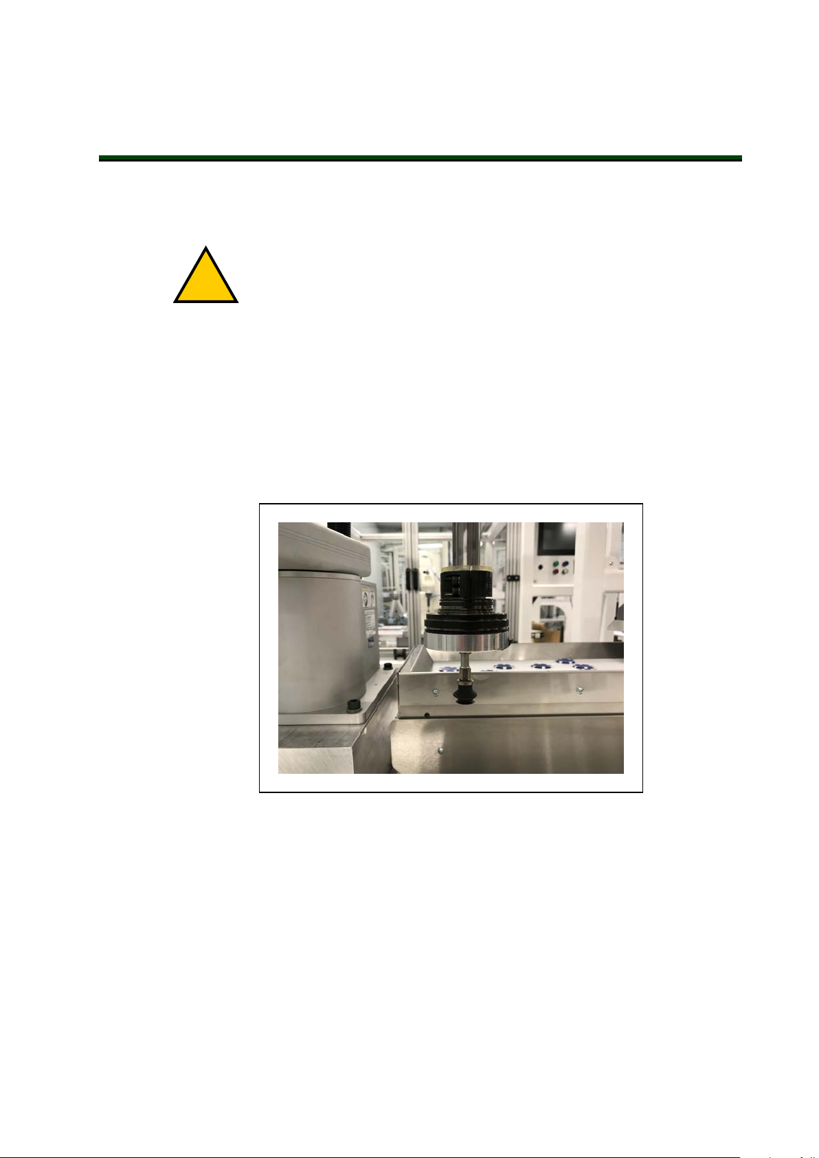
Chapter 5: Optional Equipment Installation
!
This chapter describes the process for installing various robot options such as end-effectors,
solenoids, camera brackets, and adjustable hardstops.
DANGER: Do not make modifications to the robot that are not described in
this document. Doing so can result in personal and equipment danger.
NOTE: Additional optional equipment installation may be necessary for IP65
and Cleanroom robot options. Refer to IP65 Option Considerations on page
153Cleanroom Option Considerations on page 167
5.1 Installing End-Effectors
You must provide, install, and ground (if necessary) end-effector or other end-of-arm tooling.
An installed end-effector is shown in the figure below as an example.
Figure 5-1. Suction Cup End-effector Installed
You can attach end-effectors to the tool flange using four M6 screws. Refer to Tool Flange
Dimensions on page 149 formore information.
A 6 mm diameter x 12 mm dowel pin (user-supplied) fits into the hole in the tool flange and
can be used as a keying or anti-rotation device with a user-designed end-effector.
The Joint 3 quill and the tool flange are not grounded to protective earth. If hazardous voltages
are present at the end-effector, you must install a ground connection from the base of the robot
or the outer link to the end-effector. Refer to Grounding Robot-Mounted Equipment on page
85 for more information.
24402-000 Rev B eCobra 600 and 800 Robots with EtherCAT 87
Page 88

If the end-effector requires a pneumatic supply or electrical connections, use the pass-through
connections on the robot body. Refer to Robot Connections on page 17for more information.
5.2 Mounting Locations for External Equipment
The robot arm has three multi-purpose mounting locations for adding external equipment.
Each location has a set of four tapped holes.
NOTE: The cover on the outer link must be removed for lubrication maintenance. Consider this when mounting any external equipment to the outer link
cover. Refer to Maintenance on page 111 for more information.
Additional Information: Refer to Robot Physical Dimension Drawings on page
131 for mounting hole dimensional information.
The first location is on the J1 harness support as shown in the figure below at the top side of
the inner link.
Figure 5-2. External Equipment Mounting location, J1
A second external equipment mounting location is on the top side of the outer link as shown
in the figure below.
Figure 5-3. External Tooling Location, Outer Link (top)
A third external equipment mounting location is on the bottom side of the outer link.
88 eCobra 600 and 800 Robots with EtherCAT 24402-000 Rev B
Page 89
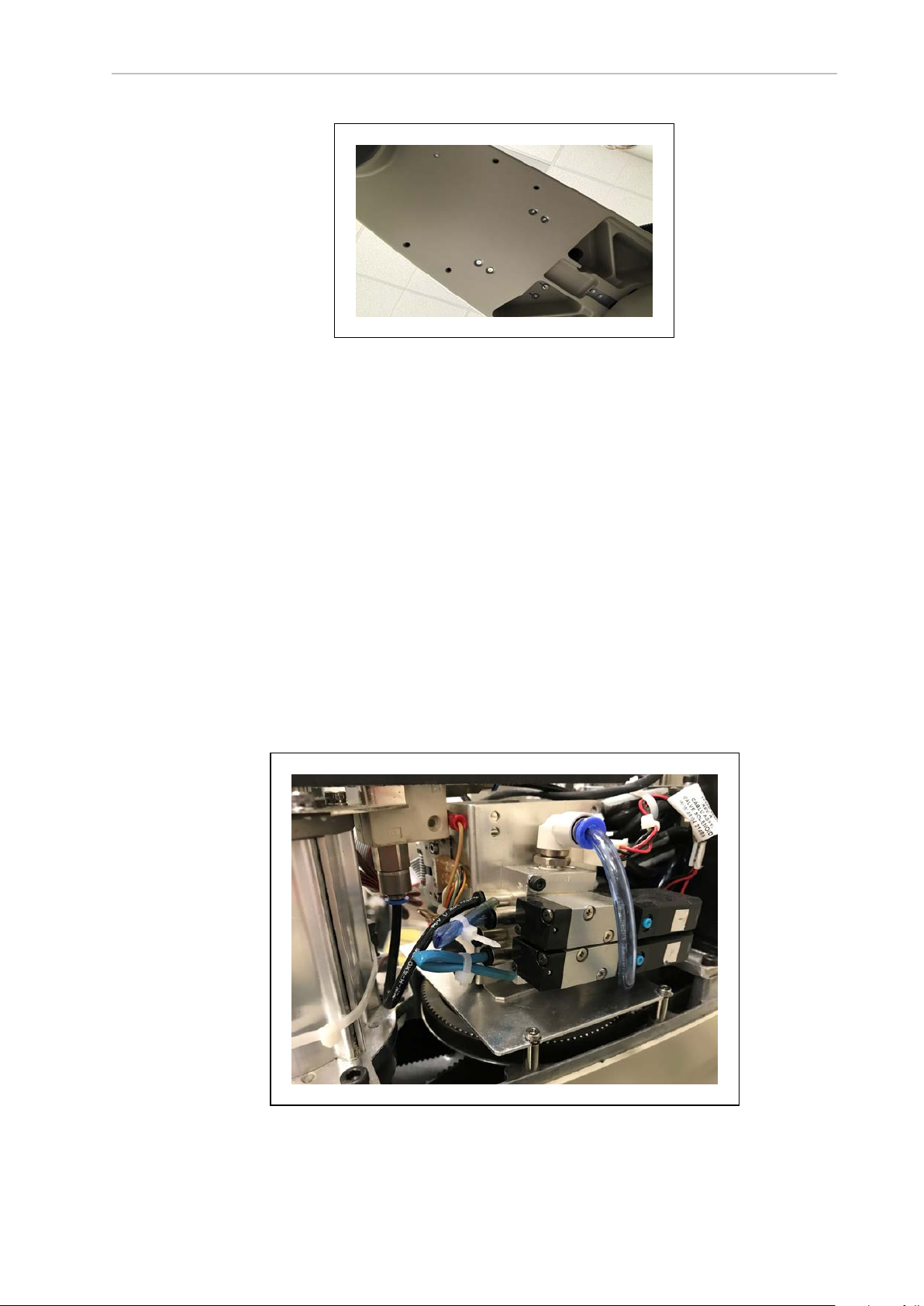
Chapter 5: Optional Equipment Installation
Figure 5-4. External Tooling Location, Outer Link (bottom)
5.3 Installing the Solenoid Valve Kit
This procedure describes how to install the SolenoidValve Kit (part number 02853-000) on a
standard robot.
NOTE: If you are installing the Solenoid Valve Kit on a robot with the IP65
option or the Cleanroom option, special considerations must be made. Refer to
Robot Solenoid Option Consideration for IP65 Robots on page 163 and Robot
Solenoid Option Consideration for Cleanroom Robots on page 168 for more
information.
Before beginning this procedure, have the following items available.
l
Hex drives
l
Cable ties
l
Diagonal wire cutters
l
Solenoid Valve Kit
Figure 5-5. Solenoid Valve Kit Assembly Installed
24402-000 Rev B eCobra 600 and 800 Robots with EtherCAT 89
Page 90
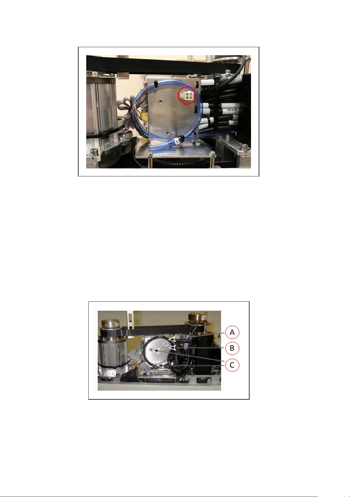
Figure 5-6. Solenoid Connector Location and Spare Air Line (blue, coiled)
Solenoid Valve Kit Installation Procedure
Use the following procedure to install the Solenoid Valve Kit.
1.
Turn OFF all power to the robot.
2.
Remove the screws from each side of the outer link cover (two screws on an eCobra 600,
three screws on an 800). Remove two screws on top and remove the cover. Retain the
screws for reassembly.
For IP65 and Cleanroom versions, refer to Outer Link Cover Removal Procedure on
page 159 for instructions on removing the link cover. Retain the screws for reassembly.
3.
Connect the Internal Solenoid Valve Cableassembly to the Solenoid Manifold assembly,
by plugging the SOL 1 connector into Valve 1 and SOL 2 into Valve 2.
Figure 5-7. Solenoid Mounting Bracket with Connector and Spare Air Line
90 eCobra 600 and 800 Robots with EtherCAT 24402-000 Rev B
Page 91

Chapter 5: Optional Equipment Installation
Key Meaning
A Spare air line
B Connector for solenoid valve (labeled SOLND)
C
Self-clinching nuts to mount the solenoid manifold
4.
Cut and discard the cable ties holding the spare air line at the top of the mounting
bracket. Move the air line out of the way to mount the solenoid manifold. See the preceding figure.
5.
Mount the solenoid manifold onto the bracket using the supplied M3 x 25 mm screws
and washers.
Figure 5-8. Solenoid Placement Using Mounting Hardware
Key Meaning
A Air intake coupling with spare air line
B Tubing connected to output port
C
Mounting screws for solenoid assembly
6.
Insert the spare air line into the air intake coupling of the solenoid manifold. Make sure
to push the air line in all the way and secure it in place by the intake coupling. Confirm
by gently pulling the air line.
NOTE: If you are installing on a Cleanroom or IP65 robot, the spare air line is
used to either evacuate or pressurize the robot. You will have to provide 6 mm
tubing to run connect one of the 6 mm user air lines at the Joint 2 cover to the air
intake coupling mentioned above.
7.
Plug the connector plug into the female connector jack (marked SOLND) on the bracket.
8.
Use cable ties to secure air line to the bracket as needed.
9.
Install the appropriate lengths of approximately 4 inch plastic tubing (supplied) into the
two output ports on the manifold.
10.
Route the tubing up along the tower bracket next to the quill and down through the
24402-000 Rev B eCobra 600 and 800 Robots with EtherCAT 91
Page 92
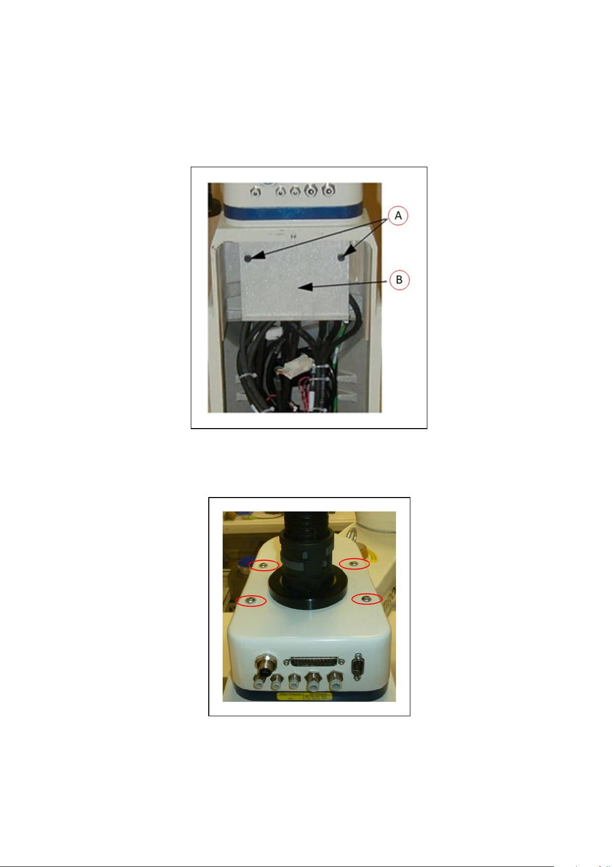
center of the quill. Use cable ties as needed to secure the tubing.
11.
Loosen the securing screw on the robot chassis and lower the chassis down flat.
12.
Remove the cable strap plate by removing two screws and split washers. See the following figure. This allows the harness to move when you lift the J1 cover in the next
step. Retain the screws for re-assembly.
Figure 5-9. Removing the Cable Strap Plate showing two M5x8 screws (A) and the cable strap
plate (B)
13.
Remove the four screws from the Joint 1 cover. Retain the screws for re-assembly.
Figure 5-10. Joint 1 Cover Screws (circled)
92 eCobra 600 and 800 Robots with EtherCAT 24402-000 Rev B
Page 93

14.
!
Disconnect the tubing from the 6 mm User Air fitting shown in the two preceding figures. Fold the tubing out of the way and restrain using cable ties.
15.
Locate the spare air line contained in the tubing bundle inside the front end of the
cover. Remove the spare air line from the bundle.
16.
Insert the spare air line into the back of the empty 6 mm User Air fitting.
NOTE: This 6 mm User Air connector and the 6 mm User Air connector at the
top of are not available for other uses after this modification.
17.
Reinstall the Joint 1 cover, ensuring that all tubing is inside the cover and nothing gets
crimped or pinched while pushing the cover into position. Reinstall four screws to
secure the cover. Tighten the screws to 1.6 N·m.
18.
Reinstall the cable strap plate removed earlier in the procedure.
19.
Raise the robot chassis to the closed position and tighten the securing screw.
20.
Reinstall the outer link cover and tighten the screws to 1.6 N·m.
Testing Solenoid Valve Kit Installation
Chapter 5: Optional Equipment Installation
Use the following procedure to test the solenoid valve kit installation.
WARNING: INJURY RISK.
Disconnect robot high pressure air until this test has been done to prevent unsecured pneumatic lines from accidentally injuring personnel.
1. Connect the low-pressure air supply to the 6 mm User Air connector (for non-IP65
robots, this is the modified air connector).
2. Test each solenoid by turning ON the output signal associated with the valve(s).
5.4 Installing the Camera Bracket Kit
Use the following information to understand the installation procedure for the Camera Bracket
Kit.
Tools Required
l
M4 hex wrench
l
M3 hex wrench
Procedure
Use the following procedure to install the Camera Bracket Kit.
1.
Install the camera plate to the outer link with four M5 x 12 mm screws using the mounting holes shown in the figure below.
24402-000 Rev B eCobra 600 and 800 Robots with EtherCAT 93
Page 94

Figure 5-11. External Camera Mounting Holes
2.
Install the two camera brackets to the camera plate with two washers and two M4 x 12
mm screws for each bracket. The camera brackets are not required unless you are mounting more than one camera.
3.
Mount the camera channel to the camera brackets or camera plate with
M4 x 12 mm screws.
4.
Mount the camera to the camera mount.
5.
Mount the camera and camera mount to the camera channel using M5 x 12 mm
screws.
Figure 5-12. Mounting a Camera Plate (A), Camera Brackets (B), Camera Channel (C), and Camera
Mount (D) on the Robot.
94 eCobra 600 and 800 Robots with EtherCAT 24402-000 Rev B
Page 95
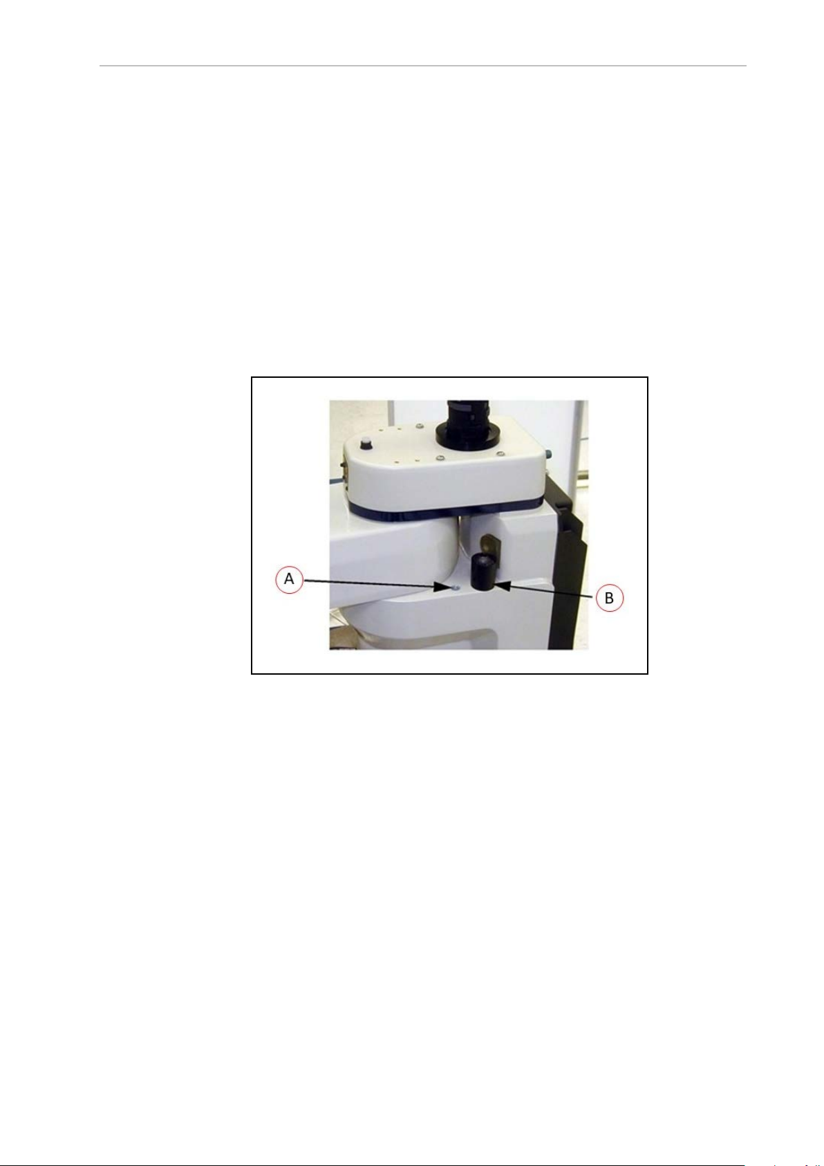
Chapter 5: Optional Equipment Installation
5.5 Installing Adjustable Hardstops
Use the following information to understand the installation procedure for the adjustable hardstops.
Joint 1 Adjustable Hardstop Installation
The Joint 1 Adjustable Hardstops consist of two black rubber stop cylinders and the required
screws to install them. There are two locations for the hardstops on each side of the robot, Position 1 and Position 2.
Tools Required
l Torque wrench
l 8mm hex bit
Figure 5-13. Hardstop Mounting Positions - Position 1 (A), Position 2 (B)
Installation Procedure
1.
Remove the plug from desired threaded hole, Position 1 or 2, on each side of the robot.
2.
Install the adjustable hardstop into the threaded hole using an 8 mm hex wrench.
Tighten to a torque of 5.1 N·m.
3.
Repeat the process on the other side of the robot.
NOTE: The two sides do not have to have a hardstop in the same position. You
can use Position 1 on one side and Position 2 (or none) on the other side.
IMPORTANT: After installing any adjustable hardstops, modify the robot joint
motion limit(s). Refer to the Sysmac Studio Version 1 Operation Manual (Cat. No.
W504) for more information. Refer to Adjustable Hardstops on page 32 for
information about robot joint range limitations.
24402-000 Rev B eCobra 600 and 800 Robots with EtherCAT 95
Page 96

Joint 2 Adjustable Hardstop Installation
The Joint 2 Adjustable Hardstops consists of two curved plates for adjustmentand a small,
black rectangular device that is the fixed hardstop. You can install the adjustable hardstop
plates in different locations, depending on how much you need to limit the Joint 2 range of
motion. The positions are spaced 30° apart.
Figure 5-14. Joint 2 Hardstop Kit
Tools Required
l Torque wrench
l 4mm hex bit
l 3mm hex bit
Installation Procedure
1.
Slide the two adjustable hardstop plates into the space between inner and outer links
(see Figure 5-15. Looking up at the inner link from underneath, align the holes in the
plates with the holes in the inner link(see Figure 5-16.
96 eCobra 600 and 800 Robots with EtherCAT 24402-000 Rev B
Page 97

Chapter 5: Optional Equipment Installation
Figure 5-15. Joint 2 Adjustable Hardstop Plates installed in Position 2 (A)
Figure 5-16. Screw Locations for Joint 2 Adjustable Hardstops (as seen from below)
Item Meaning Item Meaning
A Joint 2 Left Hardstop
D Joint 2 Negative direction
Plate installed in +81°
position
B Joint 2 Right Hardstop E Joint 2 Positive direction
24402-000 Rev B eCobra 600 and 800 Robots with EtherCAT 97
Page 98

Item Meaning Item Meaning
Plate installed in -81°
position
C 12 thru holes for M5 x
F Joint 2 Fixed Hardstop device
10 screws to install
Joint 2 hardstops, located 30° apart
2.
Use a 4 mm hex wrench to install three supplied M5 x 10 screws to secure the plate.
Tighten the screws to 4.5 N·m. Repeat the process for the second plate. The plates can be
installed in a number of different positions, depending on how much you need to limit
the range of Joint 2.
NOTE: The two hardstop sides do not have to be in the same position, so the
workspace does not have to be symmetrical.
3.
Slide the fixed hardstop device into the slot on the underside of the outer link. See Figure 5-17.
Figure 5-17. Fixed Hardstop Block for Joint 2 installed on underside of Outer Link
4.
Use a 3 mm hex wrench to install two supplied M4 x 10 screws to secure the hardstop
device. Tighten the screws to a torque of 2.5 N·m.
IMPORTANT: After installing any adjustable hardstops, modify the robot joint
motion limit(s). Refer to the Sysmac Studio Version 1 Operation Manual (Cat. No.
W504) for more information. Refer to Adjustable Hardstops on page 32 for
information about robot joint range limitations.
98 eCobra 600 and 800 Robots with EtherCAT 24402-000 Rev B
Page 99

Chapter 6: System Operation
!
!
This chapter provides information necessary to operate the robot. Read and understand this
information before attempting to use the robot.
6.1 Verifying Installation
Before using the robot after installation or other modifications, you must verify that the system
is correctly installed and that all safety equipment is working.
DANGER: PERSONAL INJURY/FATALITY HAZARD
After installing the robot, you must test it before using it for the first time. Failure to do this could result in fatality, or serious injury, or equipment damage.
Mechanical Checks
Make the following checks to verify proper mechanical installation.
l The robot is mounted in a level manner.
l
All fasteners are properly installed and tightened to the specified torque.
l
Any end-of-arm tooling is properly installed and grounded (if necessary).
l
All other peripheral equipment is properly installed and in a state where it is safe to
turn ON power to the robot.
System Cable Checks
Make the following checks to verify proper system cable installation.
IMPORTANT: Inspect all cables and connectors to ensure they are securely
fastened and free of damage.
Additional Information: Refer to Basic System Cable Layout on page 61
NOTE: The XUSR, XMCP, and XFP jumpers intentionally bypass safety con-
nections so you can test the system functionality during setup.
WARNING: PERSONALINJURYRISK
Never run a robot system, in automatic mode, with all three jumpers installed.
This would leave the system with no E-Stops.
l If a Front Panel is present, ensure it is connected to the XFP connector on the
XSYSTEMcable. If not using a Front Panel, ensure the appropriate jumper is installed.
l If a pendant is present, ensure it is connected to the XMCP on the XSYSTEM cable. If
not using a pendant, ensure the appropriate jumper is installed.
l Ensure the XSYSTEMcable is connected to the XSYSTEM connector on the robot inter-
face panel.
24402-000 Rev B eCobra 600 and 800 Robots with EtherCAT 99
Page 100

l Ensure the 24 VDC supply cable and ground wire are connected to the robot interface
panel. If required, ensure the tool flange is properly grounded.
l Ensure the 200-240 VACsupply cable is connected to the robot interface panel.
l Ensure all optional cabling is properly connected.
User-Supplied Safety Equipment Checks
Verify that all user-supplied safety equipment and E-Stop circuits are properly installed and
functioning.
Use Sysmac Studio utilities to check the safety settings of the robot as described in the table
below. Refer to the Sysmac Studio Robot Integrated System Building Function with Robot Integrated
CPU Unit Operation Manual (Cat. No. W595) for more information.
Additional Information: If the robot will not enter the high power state and dis-
plays or *Safety Systemnot Commissioned* on the Robot
StatusLEDpanel, use the utilities below to troubleshoot the system.
Table 6-1. Safety Utilities in Sysmac Studio
Utility
Description
E-Stop Configuration Utility This utility sets the E-Stop hardware delay to factory
specification.
E-Stop Verification Utility This utility verifies that the hardware E-Stop is func-
tioning correctly.
Teach Restrict Configuration Utility This utility sets the hardware Teach Restrict max-
imum speed to factory specifications.
Teach Restrict Verification Utility This utility verifies that the hardware Teach Restrict
is functioning correctly.
Safety Equipment Check Prerequisites
When checking safety equipment with the utilities described above, the following prerequisites
are necessary.
l Sysmac Studio must be installed and available.
l If Teach Restrict verification is necessary, a TeachPendant must be available.
l The Front Panel mode selection must be in Auto.
l All E-Stops must be deactivated.
l If E-Stop or Teach Restrict configuration is necessary, the supplied jumper plug (11901-
000) must be installed on the XBELLTIO connector on the robot interface panel.
Figure 6-1. Safety Equipment CheckJumper Plug
100 eCobra 600 and 800 Robots with EtherCAT 24402-000 Rev B
 Loading...