

Page 1

Cat. No. I548-E1-01
COMMUNICATIONS MANUAL
3G3JE
Compact Simplified Inverters
Page 2

Preface
Thank you for choosing this 3G3JE-series Compact Simplified Inverter.
This Communications Manual describes Inverter communications specifications and communications setting methods.
Serial communications using the CompoWay/F communications format are supported by
3G3JE Inverters with Communications. This Communications Manual describes Inverter
communications. For information on 3G3JE installation, wiring, and operating methods,
refer to the 3G3JE User's Manual.
• This manual is to be delivered to the final end user of the product.
• After reading the manual, always keep it close at hand for reference when operating the
Inverter.
• Every effort has been made to provide detailed specifications, information on functions,
and interrelationships betw een them. Assume th at an ything not described in this man ual
cannot be performed.
• This manual is intended for the following personnel, who are assumed to have sufficient
knowledge of electrical systems (i .e., an electrical engineer or the equivalent ).
• Personnel in charge of introducing control devices
• Personnel designing the control system
• Personnel installing and connecting control devices
• Personnel managing the site where the Inverter is used
Page 3

OMRON, 2006
r
f
All rights reserved. No part of this publication may be reproduced, stored in a retrieval system, or tran smit ted, in any form, o
by any means, mechanical, electronic, photocopying, recording, or otherwise, without the prior written permission o
OMRON.
No patent liability is assumed with respect to th e use of the in fo rmation c ontain ed he rein. M oreover, because OMRON is constantly striving to improve its high-quality products, the information contained in this manual is subject to change without
notice. Every precaution has been taken in the preparation of this manual. Nevertheless, OMRON assumes no responsibility
for errors or omissions. Neither is any liability assumed for damages resulting from the use of the information contained in
this publication.
II
Page 4

Read and Understand this Manual
Please read and understand this manual before using the products. Please consult your OMRON
representative if you have any questions or comments.
Warranty and Limitations of Liability
WARRANTY
OMRON's exclusive warranty is that the products are free from defects in materials and workmanship for a
period of one year (or other period if specified) from date of sale by OMRON.
OMRON MAKES NO WARRANTY OR REPRESENTATION, EXPRESS OR IMPLIED, REGARDING NONINFRINGEMENT, MERCHANTABILITY, OR FITNESS FOR PARTICULAR PURPOSE OF THE
PRODUCTS. ANY BUYER OR USER ACKNOWLEDGES THAT THE BUYER OR USER ALONE HAS
DETERMINED THAT THE PRODUCTS WILL SUITABLY MEET THE REQUIREMENTS OF THEIR
INTENDED USE. OMRON DISCLAIMS ALL OTHER WARRANTIES, EXPRESS OR IMPLIED.
LIMITATIONS OF LIABILITY
OMRON SHALL NOT BE RESPONSIBLE FOR SPECIAL, INDIRECT, OR CONSEQUENTIAL DAMAGES,
LOSS OF PROFITS OR COMMERCIAL LOSS IN ANY WAY CONNECTED WITH THE PRODUCTS,
WHETHER SUCH CLAIM IS BASED ON CONTRACT, WARRANTY, NEGLIGENCE, OR STRICT
LIABILITY.
In no event shall the responsibility of OMRON for any act exceed the individual price of the product on which
liability is asserted.
IN NO EVENT SHALL OMRON BE RESPONSIBLE FOR WARRANTY, REPAIR, OR OTHER CLAIMS
REGARDING THE PRODUCTS UNLESS OMRON'S ANALYSIS CONFIRMS THAT THE PRODUCTS
WERE PROPERLY HANDLED, STORED, INSTALLED, AND MAINTAINED AND NOT SUBJECT TO
CONTAMINATION, ABUSE, MISUSE, OR INAPPROPRIATE MODIFICATION OR REPAIR.
III
Page 5

Application Considerations
SUITABILITY FOR USE
OMRON shall not be responsible for conformity with any standards, codes, or regulations that apply to the
combination of products in the customer's application or use of the products.
At the customer's request, OMRON will provide applicable third party certification documents identifying
ratings and limitations of use that apply to the products. This information by itself is not sufficient for a
complete determination of the suitability of the products in combination with the end product, machine,
system, or other application or use.
The following are some examples of applications for which particular attention must be given. This is not
intended to be an exhaustive list of all possible uses of the products, nor is it intended to imply that the uses
listed may be suitable for the products:
• Outdoor use, uses involving potential chemical contamination or electrical interference, or conditions or
uses not described in this manual.
• Nuclear energy control systems, combustion systems, railroad systems, aviation systems, medical
equipment, amusement machines, vehicles, safety equipment, and installations subject to separate
industry or government regulations.
• Systems, machines, and equipment that could present a risk to life or property.
Please know and observe all prohibitions of use applicable to the products.
NEVER USE THE PRODUCTS FOR AN APPLICATION INVOLVING SERIOUS RISK TO LIFE OR
PROPERTY WITHOUT ENSURING THAT THE SYSTEM AS A WHOLE HAS BEEN DESIGNED TO
ADDRESS THE RISKS, AND THA T THE OMRON PR ODUCTS ARE PROPERLY RATED AND INSTALLED
FOR THE INTENDED USE WITHIN THE OVERALL EQUIPMENT OR SYSTEM.
PROGRAMMABLE PRODUCTS
OMRON shall not be responsible for the user's programming of a programmable product, or any
consequence thereof.
IV
Page 6

Disclaimers
CHANGE IN SPECIFICATIONS
Product specifications and accessories may be changed at any time based on improvements and other
reasons.
It is our practice to change model numbers when published ratings or features are changed, or when
significant construction changes are made. However, some specifications of the products may be changed
without any notice. When in doubt, special model numbers may be assigned to fix or establish key
specifications for your application on your request. Please consult with your OMRON representative at any
time to confirm actual specifications of purchased products.
DIMENSIONS AND WEIGHTS
Dimensions and weights are nominal and are not to be used for manufacturing purposes, even when
tolerances are shown.
PERFORMANCE DATA
Performance data given in this manual is provided as a guide for the user in determining suitability and does
not constitute a warranty. It may represent the result of OMRON's test conditions, and the users must
correlate it to actual application requirements. Actual performance is subject to the OMRON Warranty and
Limitations of Liability.
ERRORS AND OMISSIONS
The information in this manual has been carefully checked and is believed to be accurate; however, no
responsibility is assumed for clerical, typographical, or proofreading errors, or omissions.
COPYRIGHT AND COPY PERMISSION
This document shall not be copied for sales or promotions without permission.
This document is protected by copyright and is intended solely for use in conjunction with the product.
Please notify us before copying or reproducing this document in any manner, for any other purpose. If
copying or transmitting this document to another, please copy or transmit it in its entirely.
V
Page 7
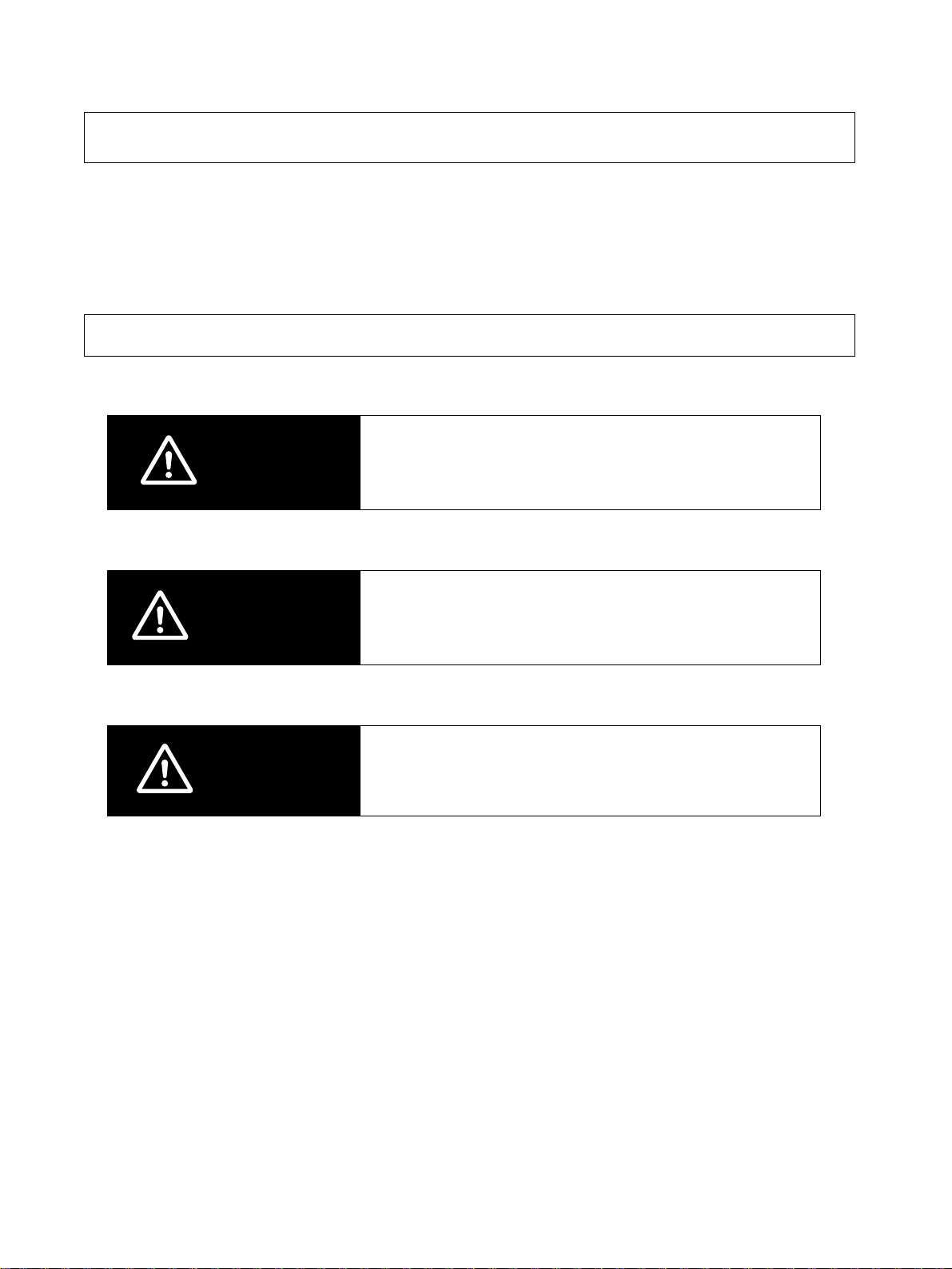
Safety Precautions
● Indications and Meanings of Safety Information
The following precautions and signal words are used to provide information to ensure the safe use of
the 3G3JE Inverter. The information provided here is vital to safety. Always observe the precautions
provided.
Meanings of Signal Words
The following signal words are used in this manual.
Indicates an imminently hazardous situation which, if
DANGER
(There are no alert statements with “DANGER” contained in this manual.)
WARNING
not avoided, is l ikely to result in serious injury or may
result in death. Additionally there may be severe property damage.
Indicates a potentially hazardous situation which, if not
avoided, will result in minor or moderate injury, or may
result in serious injury or death. Additionally there may
be significant property damage.
(There are no alert statements with “WARNING” contained in this manual.)
Indicates a potentially hazardous situation which, if not
CAUTION
avoided, may result in minor or moderate injury or in
property damage.
VI
Page 8
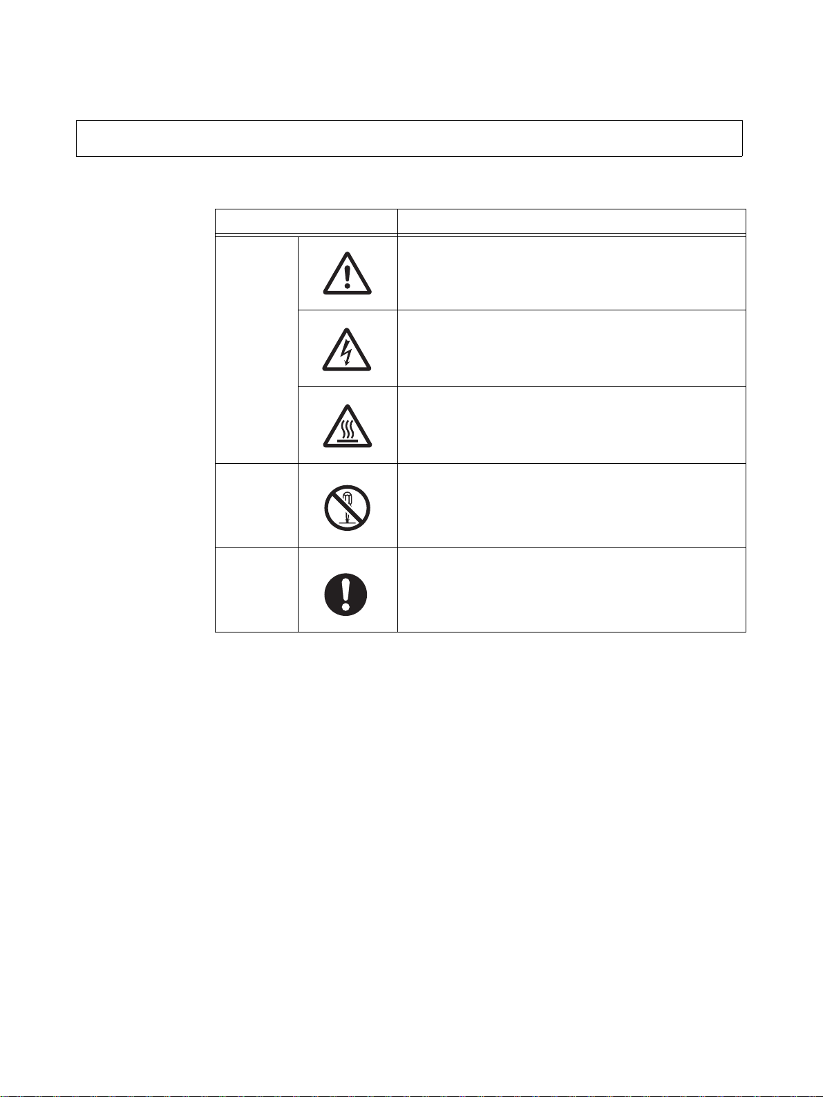
Meanings of Alert Symbols
The following alert symbols are used in this manual.
Symbol Meaning
General Caution
Indicates non-specific general cautions, warnings, and
dangers.
Electrical Shock Caution
Caution
Prohibition
Indicates possibility of electric shock under specific
conditions.
High Tempe rature Caution
Indicates possibility of burns due to high temperatures
under specific conditions.
Disassembly Prohibition
Indicates prohibitions when there is a possibility of
injury, such as from electric shock, as the result of
disassembly.
Mandatory
Caution
General Caution
Indicates non-specific general cautions, warnings, and
dangers.
VII
Page 9
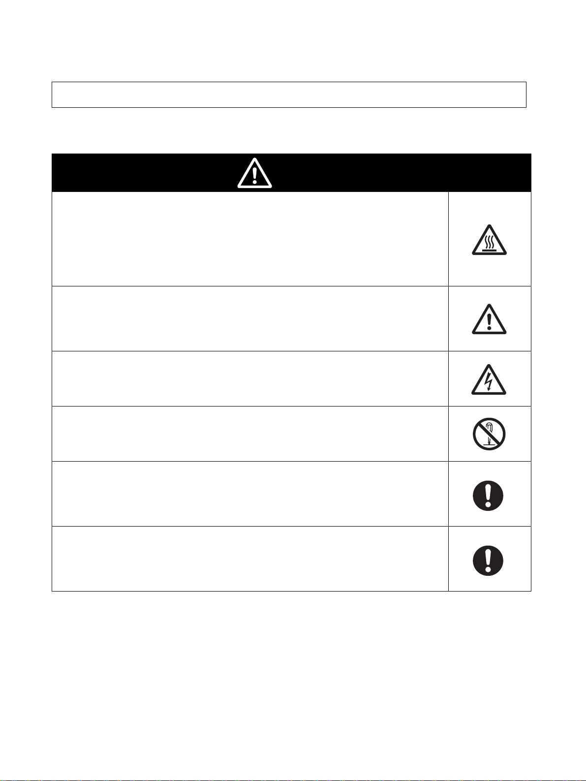
Alert Statements in this Manual
The following alert statements apply to the products in this manual. Each alert statement also
appears at the locations needed in this manual to attract your attention.
Caution
Be sure to use the specified Braking Resistor or Braking Resistor Unit.
Not doing so may occasionally result in moderate burns due to heating of the
Braking Resistor or Braking Resist or Unit.
When using a Braking Resistor or Braking Resistor Unit, be sure to install a
thermal relay to monitor the resistor temperature.
Include a sequence to turn OFF the power supply to the Inverter if the Braking
Resistor or Braking Resistor Unit overheats.
Terminals B1 and B2 are for connecting an opti onal Braking Resistor or Br aking
Resistor Unit. Do not connect an y device other than a Brakin g Resi stor or Braking Resistor Unit to these terminals.
Doing so may occasionally result in moderate fire, heating, or equipment damage.
Do not open terminal covers while the po wer is being supplied or for at least
one minute after the power has been turned OFF.
Doing so may occasionally result in minor injury from electrical shock.
Do not remove the fan cover except when replacing the fan. Before replacing
the fan, first turn OFF the power and disconnect the wiring.
Doing so may occasionally result in minor injury from electrical shock.
Install external brea k ers (MCCB) s uitab le for the Inv erter capacity o n the po wer
supply side of the Inverter and take other safety meas ures again st sh ort-circuiting in load wiring.
Not doing so may occasionally result in property damage from short-circuiting
in load wiring.
Cover the Inverter or take other measures to prevent filings or lead clippings
from entering the Inverter during installation and wiring.
The Inverter contains high-voltage components and Inv erter damage or property damage may occasionally occur if the high-voltage components are shortcircuited.
VIII
Page 10

Precautions for Safe Use
■ Installation and Storage Environment
• Do not store, install, or operate the product in any of the following locations.
• Locations subject to direct sunlight.
• Locations subject to temperatures outside the range specified in the specifications.
• Locations subject to humidity outside the range specified in the specifications.
• Locations subject to condensation resulting from severe changes in temperature.
• Locations subject to corrosive or flammable gases.
• Locations subject to exposure to combustibles.
• Locations subject to dust (especially iron dust) or salts.
• Locations subject to exposure to water, oil, or chemicals.
• Locations subject to shock or vibration.
■
Transporting, Installation, and Wiring
• Always use the original shipping box when transporting the Inverter.
• Do not apply e xcessiv e shock to t he Inv erter or drop the In verter . The In verter may mal function
or may be damaged.
• Do not connect an AC po w er suppl y v ol tage to t he U, V , and W outpu t t erminals. Doing so wi ll
damage the Inverter.
• Do not connect any load other than a three-phase inductive motor to the U, V, and W output
terminals.
• Do not connect an A C po wer supply vol tage to t he contr ol I/O t erminals. Doin g so wil l damage
the Inverter.
2
• Use 600-V polyvinyl chloride (PVC) cable with a wire size of 0.75 to 2 mm
to wire the main
circuit terminals. Also, tighten the terminal screws on the terminal block to a torque of 0.8 to
1.0 N·m.
• Take appropriate and sufficient shielding countermeasures when installing systems in the f o llowing locations. Not doing so may result in malfunctio n or equipment damage.
• Locations subject to static electricity or other forms of noise.
• Locations subject to strong electromagnetic fields and magnetic fields.
• Locations close to power lines.
■
Operation and Maintenance
• This Inverter can be set to operate from low speed to high speed. Operate the Inverter only
after sufficiently conf irming the allowable range for the motor installation being used.
• Take measures to assure safety before performing maintenance or inspection, or replacing
components.
IX
Page 11

Precautions for Correct Use
■ Installation
• Mount the product vertically on a wall or on a DIN Track. Lea v e the prescribed space bet ween
this product and the control panel surface and other devices.
■ Main Circuit Power Supply
• Use a three-phase, 200 to 230 V, 50/60 Hz power supply.
■ Operation after Power Interruptions
• If continuing operation is selected for the momentary power interruption restart selection parameter (P09), the system may unexpectedly start operation after a momentary power interruption is reset. Exercise suitable caution.
■ Operation Command Selection
• If the operation command s election parameter (P10) is set to “PLC” to enable usi ng the control
circuit terminal inputs (STF and STR), the motor may start operation when the power supply
is turned ON or an alarm is reset if the control circuit terminals are left ON. Exercise suitable
caution. Also , if signals are chec ked during operation and a v oltage is inc orrectly applied to t he
control circuit terminals , the moto r ma y start moving une xpected ly. Always chec k saf ety befor e
performing signal checks.
■ Motor Overheating Protection (Electronic Thermal)
• The Inverter uses an electronic thermal to protect the motor from overheating. Set the rated
current of the motor in the rated motor current parameter (P01). If more than one motor is operated with one Inverter, set the rated motor current parameter (P01) to 0.0 to disable motor
overload detection, and install a thermal relay between the Inverter and each motor. Set the
thermal relay to the nameplate current at 50 Hz and to 1.1 times the nameplate current at 60
Hz.
■ EEPROM Lif e
• The EEPROM has a limited life. Use RAM mode when using communications or other methods to frequently write data.
■ Disposing of the Inverter
• Observe all applicable legal requirements when disposing of the Inverter.
X
Page 12

About this Manual
This manual is divided into the chapters described in the fol lowi ng tab le. Understanding ho w inf ormation is organized will enable you to use the manual more efficiently.
Chapter Contents
Chapter 1
Communications Methods
Chapter 2
CompoWay/F Communications Procedures
Chapter 3
Communications Data
Chapter 4
Appendix
Provides an overview of the communications methods used for the
3G3JE.
Describes the procedures required to use the CompoWay/F communications protocol.
Provides tables of data used in CompoWay/F communications.
Provides a table of ASCII characters.
XI
Page 13

Table of Contents
Chapter 1. Communications Methods . . . . . . . . . . . . . . . . . . . . . . . . 1-1
1-1 Overview of Communications Methods. . . . . . . . . . . . . . . . . . . . . . . . . . . . . . . . . . . . . . . . . 1-2
■Introduction . . . . . . . . . . . . . . . . . . . . . . . . . . . . . . . . . . . . . . . . . . . . . . . . . . . . . . . . . . . . 1-2
■Communications Specifications . . . . . . . . . . . . . . . . . . . . . . . . . . . . . . . . . . . . . . . . . . . . . 1-2
■Transmission Procedure . . . . . . . . . . . . . . . . . . . . . . . . . . . . . . . . . . . . . . . . . . . . . . . . . . . 1-3
■Interface . . . . . . . . . . . . . . . . . . . . . . . . . . . . . . . . . . . . . . . . . . . . . . . . . . . . . . . . . . . . . . . 1-3
■Connections and Wiring . . . . . . . . . . . . . . . . . . . . . . . . . . . . . . . . . . . . . . . . . . . . . . . . . . . 1-3
■Communications Parameters . . . . . . . . . . . . . . . . . . . . . . . . . . . . . . . . . . . . . . . . . . . . . . . 1-4
Chapter 2. CompoWay/F Communications Procedures . . . . . . . . . 2-1
2-1 Data Format . . . . . . . . . . . . . . . . . . . . . . . . . . . . . . . . . . . . . . . . . . . . . . . . . . . . . . . . . . . . . . 2-2
■Command Frame . . . . . . . . . . . . . . . . . . . . . . . . . . . . . . . . . . . . . . . . . . . . . . . . . . . . . . . . 2-2
■BCC Calculation Example . . . . . . . . . . . . . . . . . . . . . . . . . . . . . . . . . . . . . . . . . . . . . . . . . 2-3
■Communications Data . . . . . . . . . . . . . . . . . . . . . . . . . . . . . . . . . . . . . . . . . . . . . . . . . . . . 2-3
■Response Frame . . . . . . . . . . . . . . . . . . . . . . . . . . . . . . . . . . . . . . . . . . . . . . . . . . . . . . . . .2-4
■End Code Examples . . . . . . . . . . . . . . . . . . . . . . . . . . . . . . . . . . . . . . . . . . . . . . . . . . . . . . 2-5
2-2 Structure of Command Text . . . . . . . . . . . . . . . . . . . . . . . . . . . . . . . . . . . . . . . . . . . . . . . . . . 2-7
■PDU Structure . . . . . . . . . . . . . . . . . . . . . . . . . . . . . . . . . . . . . . . . . . . . . . . . . . . . . . . . . . 2-7
■Area Definitions . . . . . . . . . . . . . . . . . . . . . . . . . . . . . . . . . . . . . . . . . . . . . . . . . . . . . . . . . 2-7
■Type Code (Variable Type) . . . . . . . . . . . . . . . . . . . . . . . . . . . . . . . . . . . . . . . . . . . . . . . . 2-7
■Addresses . . . . . . . . . . . . . . . . . . . . . . . . . . . . . . . . . . . . . . . . . . . . . . . . . . . . . . . . . . . . . . 2-8
■Number of Elements . . . . . . . . . . . . . . . . . . . . . . . . . . . . . . . . . . . . . . . . . . . . . . . . . . . . . . 2-8
■List of Services . . . . . . . . . . . . . . . . . . . . . . . . . . . . . . . . . . . . . . . . . . . . . . . . . . . . . . . . . . 2-8
2-3 Detailed Description of Services . . . . . . . . . . . . . . . . . . . . . . . . . . . . . . . . . . . . . . . . . . . . . . 2-9
■Read Variable Area . . . . . . . . . . . . . . . . . . . . . . . . . . . . . . . . . . . . . . . . . . . . . . . . . . . . . . 2-9
■Write Variable Area . . . . . . . . . . . . . . . . . . . . . . . . . . . . . . . . . . . . . . . . . . . . . . . . . . . . . . 2-10
■Read Controller Attributes . . . . . . . . . . . . . . . . . . . . . . . . . . . . . . . . . . . . . . . . . . . . . . . . . 2-11
■Read Controller Status . . . . . . . . . . . . . . . . . . . . . . . . . . . . . . . . . . . . . . . . . . . . . . . . . . . . 2-11
■Echoback Test . . . . . . . . . . . . . . . . . . . . . . . . . . . . . . . . . . . . . . . . . . . . . . . . . . . . . . . . . . 2-12
■Operation Command . . . . . . . . . . . . . . . . . . . . . . . . . . . . . . . . . . . . . . . . . . . . . . . . . . . . . 2-13
2-4 Response Code List . . . . . . . . . . . . . . . . . . . . . . . . . . . . . . . . . . . . . . . . . . . . . . . . . . . . . . . . 2-16
Chapter 3. Communications Data . . . . . . . . . . . . . . . . . . . . . . . . . . . 3-1
3-1 Variable Area Setting Range List . . . . . . . . . . . . . . . . . . . . . . . . . . . . . . . . . . . . . . . . . . . . . . 3-2
3-2 Status . . . . . . . . . . . . . . . . . . . . . . . . . . . . . . . . . . . . . . . . . . . . . . . . . . . . . . . . . . . . . . . . . . . 3-4
Chapter 4. Appendix . . . . . . . . . . . . . . . . . . . . . . . . . . . . . . . . . . . . . . 4-1
4-1 ASCII List . . . . . . . . . . . . . . . . . . . . . . . . . . . . . . . . . . . . . . . . . . . . . . . . . . . . . . . . . . . . . . . 4-2
Index . . . . . . . . . . . . . . . . . . . . . . . . . . . . . . . . . . . . . . . . . . . . . . . . . . . I-1
Revision History. . . . . . . . . . . . . . . . . . . . . . . . . . . . . . . . . . . . . . . . . . R-1
XIII
Page 14

Chapter 1
Communications
Methods
1-1 Overview of Communications Methods
Page 15

Communications Methods
Chapter 1
1-1 Overview of Communications Methods
■ Introduction
3G3JE Inver ters with Communications (referred to as “Communications Models”) use communications to monitor set values and make settings. In addition, programs for communications are created
at the Inverter's host computer (e.g., a personal computer), and the host computer is used to read
and write data, send operation commands, and change the setup area. Therefore the description
provided here is from the viewpoint of the host computer.
CompoWay/F is OMRON's standard communications protocol for general serial communications.
This protocol uses a stan dard frame format, as well as commands conforming to the well-establ is hed
FINS* commands used for OMRON PLCs. This simplifies communications between the host computer and components.
*FINS (Factory In terface Network Serv ice)
The FINS protocol pro vides message communications between controllers in OMRON FA networks.
● The 3G3JE supports the following communications functions.
• Reading/writing parameters
• Operation commands
• Changing the setup area
■ Communications Specificatio ns
Item Specifications Default
Transmission line connection Multidrop --Communications method RS-485 (2-wire, half-duplex) --Synchronization method Start-s top sync hr oniz ati on --Communications baud rate 2.4, 4.8, 9.6, or 19.2 kbps 9.6 kbps
Communi cations code ASCII --Communications data bits 7 or 8 bits 7 bits
Communications stop bits 1 or 2 bits 2 bits
Error detection Verti c al par i ty (n one, even, or odd)
and BCC (Block Check Character)
Flow control --- --Interface RS-485 --Retry function --- --Communications buffer 40 bytes ---
Even
1-2
Page 16

Communications Methods
■ Transmission Procedure
Chapter 1
When the host computer transmits a command frame, the 3G3JE transmits a response frame that
corresponds to the command frame. A single response frame is returned for each command frame.
The followi ng diagram shows the operation of the command and resp onse frames.
Command frame
Host computer
3G3JE
Response frame
Command frame
Note Allow a wait time of at least 2 ms before the next command is sent after the host computer
receives a response from the 3G3JE.
■ Interface
A K3SC Interface Converter is recommended for RS-485/RS-232C (or USB) interface conversion.
Name Model Description
K3SC Interface Converter
(OMRON)
■ Connections and Wiring
● Connections
K3SC This Converter is used to convert RS-232C (or USB) to RS-485.
• Make the connections accordi ng to the host computer and 3G3JE communications specifications.
• The connection format can be either 1:1 or 1:N.
• Up to 32 nodes including the host computer can be connected in a 1:N system.
• When connecting in a 1:N system, make sure that the communications specifications are the same
for all the nodes that are connected. In addition, set a communications unit number for each node.
(For details, refer to t he communications setting items for the communications unit number setting.)
• Use shielded twisted-pair cab le for RS-485 signal wires.
● Wiring
• The total cable length is 500 m max.
• Use shielded twisted-pair cable with a wires size of AWG24 to AWG16.
• Do not solder the ends of power lines. Doing so may result in faulty contact.
• For ease of wiring and enhanced reliability, it is recommended that solderless terminals be crimped
to the control circuit wires.
• When solderless terminals are not used, the end of each wire for the control lines must be stripped
for approximately 6 mm.
• Cover the shield with tape so that the shield will not come into contact with other signal wires or
machines.
1-3
Page 17

Communications Methods
● Applicable Line Wire Size, Terminal Screws, and Torque
Chapter 1
Terminal
screw size
M3 0.5 to 0.6 N·m Stranded wire
Torque Wire type Wire size Recommended
wire size
0.2 to 1.5 mm
(AWG24 to
2
0.75 mm2
(AWG18)
Cable
Shielded twisted-pai r
cable
AWG16)
Note For details on solderless terminal siz es and wiring methods, refer to the User's Manual.
● Wiring Diagram
RS-232C/USB
USB/RS-485 or
RS-232C/RS-485
Converter
Host computer
RS-485
Signal
FG
+
−
SG
Inverter 3G3JE -A2001-FLK
-A2002B-FLK
-A2004B-FLK
RS-485
Terminal No. Signal
A
RS-485 (+)
B
RS-485 (−)
Communications
terminals
Shield
Terminator
(1/2 W)
Shield
3G3JE node
120 Ω
at end of line
RS-485
Terminal No.
A
B
Use a 120 Ω (1/2 W) terminator.
Signal
RS-485 (+)
RS-485 (−)
Communications
terminals
Note For information on wiring between the USB/RS-485 or RS-232C/RS-485 Converter and the
host computer, refer to the manual for the Conv erter.
■ Commun ications Parameters
With 3G3JE Communications Models (RS-485), communications parameters (communications unit
number, baud rate, data length, stop bits, and parity) can be set. The following table shows the communications parameters and their setting ranges.
Item Parameter No. Settings Default
Communications unit number P15 0 to 99 1
Communications baud rate P16 2.4, 4.8, 9.6, or 19.2 kbps 9.6 kbps
Communications data length P17 7 or 8 bits 7 bits
Communications stop bits P18 1 or 2 bits 2 bits
Communications parity P19 None, even, or odd Even
1-4
Page 18

Communications Methods
● Communications Unit Number
Chapter 1
P15 Communications unit number Changes during
operation
Setting range 0 to 99 Default setting 1
No
To communicate with the host computer, set a unit number for each Inverter so that the Inverters can
be recognized by the host computer. The unit number can be set to an integer value between 0 and
99.
Note When communicating with multiple Inverters, do not set the same unit number for more than
one Inv erter . If the same uni t n umber is set for more than one node, t he sy stem wil l not operat e
correctly.
• Up to 32 nodes including the host computer can be connected in a 1:N system.
• When connecting a 1:N system, mak e sure that the communi cations spec ifications are the same f o r
all the node that are connected. In addition, set a unique communications unit number for each
node.
● Communications Baud Rate
P16 Communications baud rate Changes during
operation
Setting range 2.4/4.8/9.6/19.2 (kbps) Default setting 9.6
No
This parameter sets the baud rate for communications with the host computer. The communications
baud rate settings are as follows:
2.4 (2,400 bps), 4.8 (4,800 bps), 9.6 (9,600 bps), and 19.2 (19,200 bps).
● Communications Data Length
P17 Communications data length Changes during
operation
Setting range 7/8 (bits) Default setting 7
No
This parameter sets the number of communications data bits. Set either “7 bits” or “8 bits.”
● Communications Stop Bits
P18 Communications stop bits Changes during
operation
Setting range 1/2 (bits) Default setting 2
No
This parameter sets the number of communications stop bits. Set either “1 bit” or “2 bits.”
● Communications Parity
P19 Communications parity Changes during
operation
Selected item None/even/odd Default setting Even
No
This parameter sets the communicati ons parit y. Set the parity to “none,” “even,” or “odd.”
1-5
Page 19

Communications Methods
● Communications Settings and Operation
With 3G3JE Communications Models, communications parameters are set in the initial settings
mode. Before communicating with the 3G3JE, use the Digital Operator keys to set all of the parameters. For details on making settings other than communications parameters, refer to the 3G3JE
User's Manual.
• While the motor is stopped, the mode can be changed from RUN mode or adjustment mode to initial settings mode at any time by pressing the Mode Key for one second or longer.
• The mode can be changed from initial settings mode to RUN mode by pressing the Mode Key for
one second or longer while a parameter name (P01 to P21) is displayed. (To display a parameter
name, press the Enter Key while the set value is displayed.)
• After a set value has been changed, it goes into effect when the mode is changed to RU N mode. If
the power is turned OFF while a parameter is being set and before RUN mode is entered, the
changed set value will be lost .
Chapter 1
1-6
Page 20

Communications Methods
Moving to Communications Parameters
Power ON
RUN Mode Screen Display
Frequency reference
Initial Settings
Mode Screen Display
45. 2
p01
U
When the power is turned ON, the data display and indicators (setting
and monitoring indicators) will all light, and then the present frequency
reference be displayed on the data display.
When the Mode Key is pressed for 1 s or longer, the mode will change
MM
from RUN mode to initial settings mode, and p01 will appear on the
data display.
Use the Increment and Decrement Keys to move to parameters P15
D
to P19. (The parameter that is to be set will be displayed.)
p14
(See
note.)
U
Communications
unit number
U
Communications
baud rate
U
Communications
data length
U
Communications
stop bits
U
Communications
parity
U
p15
p16
p17
p18
p19
D
D
D
D
D
D
Chapter 1
Note: Communications
parameters
U
p20
D
p21
1-7
Page 21

Communications Methods
Example: Setting Communications Parameters
Chapter 1
U
p01
p16
Display the initial settings mode screen, and then use the Increment and
Decrement Keys to display P16 (the parameter for which the setting is to
be changed in this example).
D
When the Enter Key is pressed, the present set value
for the selected parameter will be displayed.
24
Use the Increment and Decrement Keys to set a
new value. The data display will flash.
U
D
48
Press the Enter Key to enter the new setting. The data display will
stop flashing, and the parameter display will return.
1-8
Page 22

Chapter 2
CompoWay/F
Communications
Procedures
2-1 Data Format
2-2 Structure of Command Text
2-3 Detailed Description of Services
2-4 Response Code List
Page 23

CompoWay/F Communications Procedures
C
Chapter 2
2-1 Data Format
This section describes the procedures for communications according to the CompoWay/F protocol.
• Hexadecimal values are expressed by adding the prefix H' before the number, e.g., H'02.
• Numbers shown without the H' prefix are ASCII characters. (For a tabl e of ASCII codes, ref er to the
appendix.)
• The number underneath each item in a frame indicates the number of bytes.
■ Command Frame
Text
Node number
STX
1
Name Description
STX • This code (H'02) indicates the beginning of the communications frame (text).
• Always set this character in the first byte.
• If STX is received aga in dur ing recep tion, rec eption is carr ied out ag ain from the point
where STX w as received.
Node number • This number specifies the transmission's destination.
• Specify the 3G3JE's communications unit number.
• A BCD value between 00 and 99 or ASCII “XX” can be set.
• Specify “XX” for a broadcast transmission. No responses will be returned for broadcast
transmissions.
• No resp onses will be returned f rom node numbers other than the ones in the above
range.
Sub-address • The sub-address is not used with the 3G3JE.
• Always set the sub-address to “00.”
SID • This is the service ID.
• The service ID is not used with the 3G3JE.
• Always set the service ID to “0.”
Command text This is the command text area. For details, refer to 2-2 Structure of Command Text.
ETX This code (H'03) indicates the end of the text.
BCC • This is the Block Check Character.
• The BCC result is found by calculating the exclusive OR of all bytes from the node number through ETX.
Sub-address
000
2
SID
Command text
21 11
BCC calculation range
BC
ETX
2-2
Page 24

CompoWay/F Communications Procedures
■ BCC Calculation Example
Chapter 2
The BCC (Block Check Character) is determined by calculating the exclusive OR of the bytes from
the node number through ETX. The 8-bit result is written to the BCC b yte at the end of the frame.
STX Node number
H'02 0 (H'30)
BCC = H'30 + H'30 + H'30 + H'30 + H'30 + H'30 + H'35 + H'30 + H'33 + H'03 = H'35
The result of the calculation (H'35) is written to the BCC byte.
■ Communications Data
Communications
protocol
Compoway/F 8-digit hexadecimal 2's comple-
0 (H'30) 0 (H'30)
The + symbols indicate exclusive OR operations.
Sub-address SID
0 (H'30)
Set values Negative
0 (H'30)
values
ment
0 (H'30)
The decimal point is removed and the result is converted to hexadecimal.
Example conversion: 105.0
Command text
5 (H'35)
0 (H'30)
ETX
3 (H'33)
Data
→ 1050 → H'0000041A
H'03 H'35
BCC
2-3
Page 25

CompoWay/F Communications Procedures
■ Response Frame
Chapter 2
Node
number
STX
12
Sub-
address
End code BCCCommand text
ETX00
22 11
Normal Completion
End code Name Description Error detection priority
00 Normal completion The command ended normally without error. None
Error Completion
End code Name Descr ip tio n Error detection priority
0F FINS command
error
10 Parity error The sum total of bits whose received data is “1”
11 Framing error Stop bit is “0.” 1
12 Overrun error An attempt was made to transfer new data when
13 BCC error The calculated BCC value is different from the
14 Format error • The command text contains characters other
16 Sub-address error • Illegal (unsupported) sub-address.
18 Frame length error The received frame exceeds the specified (sup-
• The sp ecified FIN S comman d could n ot be executed.
• The FINS response code should indicate why
the command could not be executed.
does not match the set value of the communications parity bit.
the reception data buffer was already full.
received BCC value.
than 0 to 9 and A to F. This error do es not apply
to Echoback Tests.
(Refer to Echoback Test on page 2-12 for
details.)
• There was no SID and command text.
• “MRC/SRC” not included in command text.
• There was no sub-address, S ID, and command
text.
• The sub-ad dress was less than two characters,
and there was no SID and command text.
ported) number of bytes.
8
2
3
5
7
6
4
• An end code is returned for each command frame received that was addressed to the local node.
• No response will be returned unless the frame contained all elements up to the ETX and BCC.
• The “Error Detection Priority” indicates the priority when two or more errors occur simultaneously.
2-4
Page 26

CompoWay/F Communications Procedures
■ End Code Examples
Chapter 2
The following examples show the end code when a command did not end normally.
Example 1: Illegal Sub-address, No SID, and No Command Text
• If there is an illegal sub-address , and no SID or command te xt, the resp onse end code will be
16 (sub-address error). (If the sub-address is received, the response end code is 16 because
a sub-address error has a higher error detection priority than a format error.)
Command
Node
number
STX
Sub-
address
BCC
ETX0A
Response
Node
number
STX
End code is “16” (sub-address error).
Sub-
address
End
code BCC
ETX0A16
Example 2: No Command Text
• If there is no command text , the response end code will be 14 (format error).
Command
Node
number
STX
Sub-
address
BCCSID
ETX000
Response
Node
number
STX
Sub-
address
0014
End
code
ETX
The end code is “14” (format error).
BCC
2-5
Page 27

CompoWay/F Communications Procedures
C
Chapter 2
Example 3: No Node Number Provided
• If there is no node number (or if it is lacking a character), there will be no response.
Command
BCC
STX
ETX
The node number is lacking one character.
Response
There is no response.
Example 4: No Sub-address and Illegal BCC
• If there is no sub-address, and the BCC is illegal, the sub-address will be regarded as 00 and
the end code will be 13 (BCC error).
Command
Node
number
STX
BCC
ETX Err
Response
Node
number
STX
The sub-address is “00” and the end code is “13” (BCC error).
Sub-
address
0013
End
code
BC
ETX
2-6
Page 28

CompoWay/F Communications Procedures
Chapter 2
2-2 Structure of Command Text
■ PDU Structure
• An MRC (Main Request Code) and SRC (Sub-Request Code) follo wed b y the v arious required data
are transferred in the command text field.
Service Request P D U
MRC SRC Data
• The MRES (Main Response Code) and SRES (Sub-Response Code) are transferred in the
response frame following the MRC and SRC. Data is then transferred following the MRES and
SRES.
Service Response PDU (Normal Response)
MRC SRC MRES SRES Data
• If the specified command text could not be executed, the service response PDU will contain only
the MRC, SRC, MRES, and SRES.
MRC SRC MRES SRES
MRES and SRES will provide a response code other than a code for normal completion.
■ Area Definitions
Only the variable area is used.
■ Type Code (Variable Type)
The followi ng tables show the variable area type codes.
Variable type (1 byte)
MSB LSB
110000
Read/Write
0: Read only
Access size
11: Double word
Area
0: Setup area 0
1: Setup area 1
1: Read/Write
The followi ng table summarizes setup areas 0 and 1.
Area Description
Setup area 0 This area groups together the RUN Mode and Adjustment Mode.
Setup area 1 This is the area for the Initial Settings Mode.
2-7
Page 29

CompoWay/F Communications Procedures
Chapter 2
The variable type is converted to 2-byte ASCII and appended to the frame.
The followi ng table shows the available variable types.
Variable type Description
C0 Double-word data. R/O (read only) parameters for setup area 0.
C1 Double-word data. R/W (read/write) parameters for setup area 0.
C3 Double-word data. R/W parameters for setup area 1.
Note Setup area 1 has no read-only parameters, so there is no variable type “C2.”
■ Addresses
An address is appended to the variable type. Express addresses in 2-byte hexadecimal and append
them for each specified access size.
■ Number of Elements
Specify the number of elements within the range “0000 to 0002.” The number of elements is
expressed in 2-byte hexadecimal.
■ List of Services
MRC SRC Name of service Processing
01 01 Read Variable Area This service reads from the variable area.
01 02 Write Variable Area This service writes to the variable area.
05 03 Read Controller Attributes This service reads the model number and communications
buffer size.
06 01 Read Controller Status This service reads the operating status.
08 01 Echoback Test This service performs an echoback test.
30 05 Operation Command This service performs operations such as resets and mov-
ing to Setup Area 0 or 1.
Note No services will be accepted and no responses will be returned when a memory error occurs
or during initial status (until normal operati on begins after the power is turned ON).
2-8
Page 30

CompoWay/F Communications Procedures
2-3 Detailed Description of Services
■ Read Variable Area
This service reads data from the variable area.
Service Request P D U
Chapter 2
MRC
0001
222 4 2 4
SRC
01
Variable type
Bit position
Number of elementsRead start address
Service Response PDU
MRC
01
2 2 4 0, 8, or 16
1.Variable Type and Read Start Address
For details on variable types and read start addresses, refer to Chapter 3 Communications Data.
2.Bit Position
Always “00.” The 3G3JE does not support bit access.
3.Number of Elements
0000 The read operation is not performed (read data is not appended to the service
0001 or 0002 The read operation is performed, and processing ends in a normal comple-
4.Response Code
SRC Response code Read data (for number of elements)
01
Number of elements Processing
response PDU), and processing ends in a normal completion.
tion.
Normal Completion
Response code Name Description
0000 Normal completion No errors were found.
Error Completion
Response code Error name Description
1001 Command too long The command is too long.
1002 Command too short The command is too short.
1101 Area type error The variable type is wrong.
1103 Start address out-of-range
error
110B Response too long The number of elements is larger than 0002. (Number
1100 Parameter error Bit position is not 00.
2203 Operation error CPU or EEPROM error
The read start address is out of range.
of elements > 0002)
2-9
Page 31

CompoWay/F Communications Procedures
■ Write Variable Area
This service writes data to the variable area.
Service Request PDU
Chapter 2
MRC
01
2
SRC
02
Variable type
2
Write start address
4
Bit position
00
Number of elements
22 4 0, 8, or 16
Write Data (for number of elements)
Service Response PDU
MRC
01
22 4
1.Variable Type and Write Start Address
For details on variable types and write start addresses, refer to Chapter 3 Communications Data.
2.Bit Position
Always “00.” The 3G3JE does not support bit access.
3.Number of Elements
Number of elements Processing
0000 The write operation is not performed and processing ends in a normal completion.
0001 to 0002 The write operation is performed and processing ends in a normal completion.
4.Response Code
SRC Response code
02
(Do not append write data to the service request PDU.)
Normal Completion
Response code Name Description
0000 Norm al co mpl eti on No errors were found.
Error Completion
Response code Error name Description
1002 Command too short The command is too short.
1101 Area type error The variable type is wrong.
1103 Start address out-of-range
error
1104 End address out-of-range
error
1003 Number of elements/data
mismatch
1100 Parameter error • Bit position is not 00.
3003 Read-only error An attempt was made to write to variable type “C0.”
2203 Operation error • Attempted to write to a parameter in setup area 1
The write start address is out of range.
The write end address (write start address + number of
elements) exceeds the final address of the variable
area.
The number of data does not match the number of elements.
• The write data is out of the setting range.
from setup area 0.
• CPU or EEPROM error
2-10
Page 32

CompoWay/F Communications Procedures
■ Read Controller Attributes
This service reads the model number and communications b uffer size.
Service Request P D U
Chapter 2
MRC
05
22
SRC
03
Service Response PDU
MRC
0 0028503
22 4 10 4
1.Model Number
The model number is expressed in 10-b yte ASCII. When 10 b ytes are not required, the remaining
bytes are filled with spaces.
Example of the Model Number:
The model number will be given as f ollows f or the 3G3JE-A2002B-FLK (maximum motor capaci ty:
0.2 kW, braking resistance contr ol, RS-485 communications).
2.Buffer Size
The communications buf fer si ze is e xpressed in 2- byte he xadecimal, and read af ter being con verted to 4-byte ASCII.
Buffer size: 40 bytes (= H'0028)
3.Response Code
SRC Model No. Buffer sizeResponse code
3G3J E202 BF
Normal Completion
Response code Name Description
0000 Normal completion No errors were found.
Error Completion
Response code Error name Description
1001 Command too long The command is too long.
2203 Operation error CPU or EEPROM error
■ Read Controller Status
This service reads the operating status and error status .
Service Request P D U
MRC
06
22
SRC
01
2-11
Page 33

CompoWay/F Communications Procedures
Service Response PDU
Chapter 2
MRC
06
22 242
SRC
01
Response code
Operating
status
Related
information
1.Operating Status
Operating status Description
00 Operation is being performed (including when operation has stopped automatically
because a protective function has operated).
01 Operation is not being performed.
2.Related Information
76543210
Bit position
Forward operation
Reverse operation
Protective function operated (when any protective function is ON)
Multifunction output operation (when multifunction output terminal is ON)
Not used.
Not used.
Not used.
Not used.
3.Response Code
Normal Completion
Response code Name Description
0000 Norm al co mpl eti on No errors were found.
Error Completion
Response code Error name Description
1001 Command too long The command is too long.
2203 Operation error CPU or EEPROM error
■ Echoback Test
This service performs an echoback test.
Service Request PDU
MRC
08
2 2 0 to 23
SRC Test data
01
Service Response PDU
MRC
08
2 2 0 to 23
SRC4Response code Test Data
01
2-12
Page 34

CompoWay/F Communications Procedures
Chapter 2
1.Test Data
Set between 0 and 23 bytes of user-defined test data.
Set a valu e f or the t est data within t he range s sho wn bel ow accor ding to the comm unications data
length.
Communications data length Test Data
8 bits ASCII data: H'20 to H'7E or H'A1 to H'FE
7 bits ASCII data: H'20 to H'7E
Note Do not set the value H'40. No response will be returned if this value is included.
2.Response Code
Normal Completion
Response code Name Description
0000 Normal completion No errors were found.
Error Completion
Response code Error name Description
1001 Command too long The command is too long.
2203 Operation error CPU or EEPROM error
■ Operation Command
The commands supported by the 3G3JE are listed in the following table. Refer to this table for command codes and related inf ormation.
Service Request P D U
MRC
30
2222
SRC
05
Command
code
Related
information
Service Response PDU
MRC
30
22 4
SRC
05
Response code
2-13
Page 35

CompoWay/F Communications Procedures
1.Command Codes and Related Information
Command code Command Related information
01 RUN/STOP 00: Run
01: Stop/Reset protective function
02 Frequency References 1 to 4 00: Frequency reference 1
01: Frequency reference 2
02: Frequency reference 3
03: Frequency reference 4
03 Forward/Rev erse Operation 00: Forward operation
01: Reverse operation
04 Write Mode 00: Backup
01: RAM
05 Save RAM Data 00
06 Parameter Initialization 00
07 Software Reset 00
08 Move to Setup Area 00: Move to setup area 0
01: Move to setup area 1
09 Accumulated Operating Time
Clear
2.Operation Commands and Precautions
00
Chapter 2
•RUN/STOP
Command code 01 is used to start and stop operation. It is also used to clear error s when an
error has occurred or a pr otective functi on has operated. R UN/ST OP can be used only in setup
area 0.
• Frequency References 1 to 4
Command code 02 is used to switch between four frequency references that are set in advance. All four frequency references can be recorded in t he Inverter. Frequency References 1
to 4 can be used only in setup area 0.
• Forward/Reverse Operation
Command code 03 is used to change the direction of motor rotation and can be used regardless of the RUN/STOP status. The direction will return to f orwa rd rotation whenever the power
supply is turned ON or setup area 1 is entered. An operation error will occur if reverse operation is set in the related information when reverse operation is prohibited. The Forward/Reverse Operation can be used only in setup area 0.
• Write Mode
Command code 04 is used to set the mode for writing frequency references using communications. The Write Mode can be used only in setup area 0. (The default setting for the write
mode is Backup Mode.)
• Backup Mode: The frequency reference is written to EEPROM using communications.
• RAM Mode: The frequency reference cannot be written to EEPROM using communications. Changes to the frequency reference made with key operations are writ ten each ti me to EEPROM. When
frequently changing the frequency reference, use RAM Mode.
• Save RAM Data
Command code 05 is used to write the frequency reference to
RAM data can be saved in setup area 0 or 1. The write mode will not be changed.
EEPROM usin g co mm un i c at io ns.
• Paramet er Initialization
Command code 06 is used to initialize all parameters except for the Accumulate Operating
Time to their default values. Parameters can be initialized only in setup area 1.
2-14
Page 36

CompoWay/F Communications Procedures
• Software Reset
Command code 07 is used to start the processing that occurs when the power is turned ON.
A software reset can be performed in setup area 0 or 1. (There is no response to this command.)
• Move to Setup Area
Command code 08 is used to change the setup area under the f ollo wing conditions . Changing
the setup area can be performed in setup area 0 or 1.
• Operation must be stopped to move from setup area 0 to 1.
• Moving from setup area 1 to 0 is possible at any time.
• Accumulated Operating Time Clear
Command code 09 is used to clear the Accumulated Operating Time of the motor to 0.0 (0 h) .
The Accumulated Operating Time can be cleared onl y in setup area 1.
3.Response Code
Normal Completion
Response code Name Description
0000 Normal completion No errors were found.
Chapter 2
Error Completion
Response code Error name Description
1001 Command too long The command is too long.
1002 Command too short The command is too short.
1100 Parameter error The write data is out of the setting range.
2203 Operation error • A RUN/STOP command was se nt in Initial Settings
Mode.
• A Parameter Initialization command was sent in RUN
Mode or Adjustment Mode.
• EEPROM error or initialization has not been performed.
• A RUN/STOP command was output when the Operation Command Selection was set to use the PLC
(i.e., operation according to the STF/STR control
inputs).
• Reverse operation was specified even though
reverse operation is prohibited.
2-15
Page 37

CompoWay/F Communications Procedures
Chapter 2
2-4 Response Code List
Normal Completion
Response code Name Description Error detection
priority
0000 Norm al co mpl eti on No errors were found. Non e
Error Completion
Response code Name Description Error detection
priority
0401 Unsupported command The service function for the relevant
command is not supported.
1001 Command too long The command is too long. 2
1002 Command too short The command is too short. 3
1101 Area type error Wrong variable type 4
1103 Start address out-of-range
error
1104 End address out-of-range
error
1003 Number of elements/data
mismatch
110B Response too long The response exceeds the communi-
1100 Parameter error • Bit position is not “00.”
3003 Read-only error An attempt was made to write to vari-
2203 Operation error • Attempted to write to a parameter in
The read/write start address is out of
range.
The write end address (write start
address + number of elements)
exceeds the final address of the vari-
able area.
The amount of data does not match
the number of elements.
cations buffer size (when the number
of elements is larger than 0002).
• The wr ite data is out of the settin g
range.
• The command code or related information in the operation command is
wrong.
able type “C0.”
setup area 1 from setup area 0.
• CPU or EEPROM error
1
5
6
7
8
9
10
11
2-16
Page 38

Chapter 3
Communications Data
3-1 Variable Area Setting Range List
3-2 Status
Page 39

Communications Data
Chapter 3
3-1 Variable Area Setting Range List
The following table lists the data ranges for each type of variable. Refer to the individual items for
details.
● Variable Type C0
Address Name Setting range Communications notation Default Unit
0000 Frequency reference 0.0 to 120 H’00000000 to H’000004B0 10.0 Hz
0001 Output frequency --- H’00000000 to H’000004B0 --- Hz
0002 Output current --- H’00000000 to H’00000032 --- A
0003 Accumulated operat-
ing time
0004 Status --- --- --- ---
● Variable Type C1
Address Name Setting range Communications notation Default Unit
0000 Frequency reference 0.0 to 120 H’00000000 to H’000004B0 10.0 Hz
0001 Frequency reference 1 H’00000000 to H’000004B0 10.0 Hz
0002 Frequency reference 2 H’00000000 to H’000004B0 0.0 Hz
0003 Frequency reference 3 H’00000000 to H’000004B0 0.0 Hz
0004 Frequency reference 4 H’00000000 to H’000004B0 0.0 Hz
0005 Acceleration time 0.1 to 999 H’00000001 to H’00002706 10.0 s
0006 Deceleration time 0.1 to 999 H’00000001 to H’00002706 10.0 s
0007 Application selection 0: Fan applica-
--- H’00000000 to H’000003E7 --- kh
tion or pump
application
1: Conveyo r
application
H’00000000
H’00000001
1 ---
• The unit for the frequency reference, output frequency, output current, accumulated operating time,
frequency references 1 to 4, acceleration time, and deceleration time is 0.1.
Examples:
→ H’00000007
0.7
→ H’000001F4
50.0
120 (120.0)
→ H’000004B0
• The frequency reference range depends on the frequency reference upper limit and the frequency
reference lower limit.
• The acceleration time, deceleration time, and application selection cannot be written during operation. (They can be read during operation.)
• 1 kh = 1,000 hours
3-2
Page 40

Communications Data
Chapter 3
● Variable Type C3
Address Name Setting range Communications nota ti on Default Unit
0000 Rated motor current 0.0 to 2.5 H’00000000 to H’00000019 0.1 kW: 0.6
0001 Accumulated operating time
0002 DC injection braking fre-
0003 Star tup DC injection braking
0004 DC injection braking-to-stop
0005 Maximum output frequency 50.0 to 120 H’000001F4 to H’000004B0 60.0 Hz
0006 Frequency reference upper
0007 Frequency reference lower
0008 Momentar y power interrup-
0009 Operation command selection 0: Operate using Digital Operator key
000A Frequency reference selec-
000B Multi-function output selection 000: Not assigned.
000C Reverse rotation prohibit
000D Carrier frequency selection 0: 4 KHz
000E Communications unit number 0 to 99 H’00000000 to H’00000063 1 --000F Communications baud rate 0: 2.4 Kbps
10 Communications data length 0: 7 bits
11 Communications stop bit 0: 1 bit
12 Communications parity 0: None
standard
quency
time
time
limit
limit
tion restart selection
tion
selection
0.0 to 99.9 H’00000000 to H’000003E7 20.0 kh
0.0 to 5.0 H’00000000 to H’00000032 3.0 Hz
0.0 to 10.0 H’00000000 to H’00000064 0.0 s
0.0 to 10.0 H’00000000 to H’00000064 0.5 s
0.1 to 120 H’00000001 to H’000004B0 60.0 Hz
0.0 to 120 H’00000000 to H’000004B0 0.0 Hz
0: Do not continue operation.
1: Continue operation if power interrup-
tion is 0.5 s or less.
2: Always continue operation.
operations.
1: Operate using the STF/SFR control
inputs. (RUN/STOP commands sent
via communications will be disabled.)
The communications type is always 0.
(The frequency references set by Digital
Operator keys and by communications
are enabled).
001: Zero speed (Output turned ON
when the output frequency is 0 Hz
or operation is stopped.)
002: Frequency matching (Output turned
ON when the output frequency and
the frequency reference are the
same.)
003: Reverse operation (Output turned
ON when the direction of rotation is
set for reverse operation.)
0: Reverse rotation enabled.
1: Reverse operation prohibited (i.e.,
reverse operation not possible).
1: 7 KHz
1: 4.8 Kbps
2: 9.6 Kbps
3: 19.2 Kbps
1: 8 bits
1: 2 bits
1: Even
2: Odd
H’00000000
H’00000001
H’00000002
H’00000000
H’00000001
H’00000000 0
H’00000000
H’00000001
H’00000002
H’00000003
H’00000000
H’00000001
H’00000000
H’00000001
H’00000000
H’00000001
H’00000002
H’00000003
H’00000000
H’00000001
H’00000000
H’00000001
H’00000000
H’00000001
H’00000002
0.2 kW: 1.0
0.4 kW: 2.0
0 ---
0 ---
0 ---
1 ---
0 ---
2 ---
0 ---
1 ---
1 ---
A
• The unit for the rated motor current, accumulated operating time standard, DC injection braking frequency, star tup DC injection braking time, DC injection braking-to-stop time, maximum output frequency, frequency reference upper limit, and frequency reference lower limit is 0.1.
Examples:
0.7→ H’00000007
50.0 → H’000001F4
120 (120.0) → H’000004B0
3-3
Page 41

Communications Data
3-2 Status
The figure below shows the st ructure of the stat us data.
16 15 14 13 12 11 10 9 8 7 6 5 4 3 2 1 0
0
00 0
0
0
Chapter 3
0
Overcurrent protection
Not used.
Not used.
Motor overload protection
Overvoltage protection
Undervoltage protection
Not used.
Radiation fin overheat protection
Cooling fan fault
Braking IGBT fault
Accumulated time alarm
Not used.
Charge indication
Not used.
Not used.
Not used.
Status
0 (OFF) 1 (ON)
Not triggered
Not triggered
Not triggered
Not triggered
Not triggered
Not triggered
No alarm
Not triggered
Triggered
---
--Triggered
Triggered
Triggered
--Triggered
Triggered
No fault
--Triggered
---
---
---
---
---
---
Fault
Alarm
---
---
---
---
31 30 29 28 27 26 25 24 23 22 21 20 19 18 17 16 15
0
00
000
000
Status 0 (OFF)
Write mode
EEPROM
Setup area
Not used.
Not used.
Not used.
Not used.
Not used.
Forward/stop
Reverse/stop
Frequency matching
Zero speed
Not used.
Not used.
Not used.
Not used.
Backup
RAM = EEPROM
Setup area 0
---
---
---
---
--Forward
Reverse
Doesn't match
Not zero
---
---
---
---
1 (ON)
RAM
RAM = EEPROM
Setup area 1
---
---
---
---
--Stop
Stop
Match
Zero
---
---
---
---
3-4
Page 42

Appendix
4-1 ASCII List
Chapter 4
Page 43

Appendix
4-1 ASCII List
Chapter 4
b8
b7 0 0 0 0 1 1 1 1
b6 0 0 1 1 0 0 1 1
b5 0 1 0 1 0 1 0 1
b8 b7 b6 b5 b4 b3 b2 b1
0 0 0 0
0 0 0 1
0 0 1 0
Even parity
0 0 1 1
0 1 0 0
0 1 0 1
0 1 1 0
0 1 1 1
1 0 0 0
1 0 0 1
1 0 1 0
1 0 1 1
1 1 0 0
1 1 0 1
1 1 1 0
1 1 1 1
C
0 1 2 3 4 5 6 7
R
SPACE
0 NUL DLE
1 SOH DC1 ! 1 A Q a q
2 STX DC2 " 2 B R b r
3 ETX DC3 # 3 C S c s
4 EOT DC4 $ 4 D T d t
5 ENQ NAK % 5 E U e u
6 ACK SYN & 6 F V f v
7 BEL ETB ' 7 G W g w
8 BS CAN ( 8 H X h x
9 HT EM ) 9 I Y i y
A LF SUB * : J Z j z
B VT ESC + ; K [ k {
C FF FS , < L \ l |
D C R GS - = M ] m }
E SO RS . > N ^ n ~
F SI US / ? O _ o DEL
0 @ P ` p
4-2
Page 44

Index
A
addresses, 2-8
area definitions
ASCII list, 4-2
, 2-7
B
BCC, 2-2
C
command frame, 2-2
command text, 2-2
structure
communications baud rate, 1-4
communicati ons data, 2-3
communications data length
communications functions, 1-2
communications methods, 1-2
communications parity
communications specifications, 1-2
communications stop bits, 1-4
communications unit number
connections, 1-3
controller attributes
reading
controller status
reading
, 2-7
, 1-4
, 1-4
, 1-4
, 2-11
, 2-11
D
data format, 2-2
data ranges, 3-2
E
Echoback Test, 2-12
EEPROM, X, 2-14
electronic thermal
elements, number of, 2-8
end codes, 2-4
ETX
, 2-2
, X
number of elements
, 2-8
O
Operation Command, 2-13
P
parameters
P15 (communications unit number), 1-4
P16 (communications baud rate)
P17 (communications data length), 1-4
P18 (communications stop bits), 1-4
P19 (communications parity)
PDU structure, 2-7
, 1-4
R
Read Controller Attributes, 2-11
Read Controller Status, 2-11
Read Variable Area
response codes, 2-16
response frame, 2-4
, 2-9
S
services
details
, 2-9
list, 2-8
SID
, 2-2
status, 3-4
STX, 2-2
sub-address
, 2-2
T
transmission procedure, 1-3
type codes, 2-7
V
variable area, 3-2
reading, 2-9
writing
, 2-10
, 1-4
I
interface, 1-3
M
motor overheating protection, X
N
node number, 2-2
W
wire size, 1-4
wiring, 1-3
wiring diagram, 1-4
I-1
Page 45

Revision History
A manual revisi on code appears as a suffix to the catalog number on the front cover of the manual.
Cat. No. I548-E1-01
Revision code
The following table outlines the changes made to the manual during each revision. Page numbers
refer to the previous version.
Revision code Date Revised content
01 June 2006 Original production
R-1
 Loading...