

Page 1

3G3JE
Compact Simplified Inverters
Cat. No. I547-E1-02
USER’S MANUAL
Page 2

Preface
Thank you for choosing this 3G3JE-series Compact Simplified Inverter.
This User's Manual describes Inverter installation and wiring, the parameter
settings required for operation, and troubleshooting and inspection procedures.
• This manual is to be delivered to the final end user of the product.
• After reading the manual, always keep it close at hand for reference when operating the
Inverter.
• Every effort has been made to provide detailed specifications, information on functions,
and interrelationships between them. Assume that anything not described in this manual
cannot be performed.
• This manual is intended for the following personnel, who are assumed to have sufficient
knowledge of electrical systems (i.e., an electrical engineer or the equivalent).
• Personnel in charge of introducing control devices
• Personnel designing the control system
• Personnel installing and connecting control devices
• Personnel managing the site where the Inverter is used
• Refer to the Communications Manual for information on communications commands for
3G3JE Inverters with communications.
Page 3

USER’S MANUAL
3G3JE
Compact Simplified Inverters
Page 4

II
OMRON, 2006
All rights reserved. No part of this publication may be reproduced, stored in a retrieval system, or transmitted, in any form, o
r
by any means, mechanical, electronic, photocopying, recording, or otherwise, without the prior written permission o
f
OMRON.
No patent liability is assumed with respect to the use of the information contained herein. Moreover, because OMRON is constantly striving to improve its high-quality products, the information contained in this manual is subject to change without
notice. Every precaution has been taken in the preparation of this manual. Nevertheless, OMRON assumes no responsibility
for errors or omissions. Neither is any liability assumed for damages resulting from the use of the information contained in
this publication.
Page 5

III
Read and Understand this Manual
Please read and understand this manual before using the products. Please consult your OMRON
representative if you have any questions or comments.
Warranty and Limitations of Liability
WARRANTY
OMRON's exclusive warranty is that the products are free from defects in materials and workmanship for a
period of one year (or other period if specified) from date of sale by OMRON.
OMRON MAKES NO WARRANTY OR REPRESENTATION, EXPRESS OR IMPLIED, REGARDING NONINFRINGEMENT, MERCHANTABILITY, OR FITNESS FOR PARTICULAR PURPOSE OF THE
PRODUCTS. ANY BUYER OR USER ACKNOWLEDGES THAT THE BUYER OR USER ALONE HAS
DETERMINED THAT THE PRODUCTS WILL SUITABLY MEET THE REQUIREMENTS OF THEIR
INTENDED USE. OMRON DISCLAIMS ALL OTHER WARRANTIES, EXPRESS OR IMPLIED.
LIMITATIONS OF LIABILITY
OMRON SHALL NOT BE RESPONSIBLE FOR SPECIAL, INDIRECT, OR CONSEQUENTIAL DAMAGES,
LOSS OF PROFITS OR COMMERCIAL LOSS IN ANY WAY CONNECTED WITH THE PRODUCTS,
WHETHER SUCH CLAIM IS BASED ON CONTRACT, WARRANTY, NEGLIGENCE, OR STRICT
LIABILITY.
In no event shall the responsibility of OMRON for any act exceed the individual price of the product on which
liability is asserted.
IN NO EVENT SHALL OMRON BE RESPONSIBLE FOR WARRANTY, REPAIR, OR OTHER CLAIMS
REGARDING THE PRODUCTS UNLESS OMRON'S ANALYSIS CONFIRMS THAT THE PRODUCTS
WERE PROPERLY HANDLED, STORED, INSTALLED, AND MAINTAINED AND NOT SUBJECT TO
CONTAMINATION, ABUSE, MISUSE, OR INAPPROPRIATE MODIFICATION OR REPAIR.
Page 6

IV
Application Considerations
SUITABILITY FOR USE
OMRON shall not be responsible for conformity with any standards, codes, or regulations that apply to the
combination of products in the customer's application or use of the products.
At the customer's request, OMRON will provide applicable third party certification documents identifying
ratings and limitations of use that apply to the products. This information by itself is not sufficient for a
complete determination of the suitability of the products in combination with the end product, machine,
system, or other application or use.
The following are some examples of applications for which particular attention must be given. This is not
intended to be an exhaustive list of all possible uses of the products, nor is it intended to imply that the uses
listed may be suitable for the products:
• Outdoor use, uses involving potential chemical contamination or electrical interference, or conditions or
uses not described in this manual.
• Nuclear energy control systems, combustion systems, railroad systems, aviation systems, medical
equipment, amusement machines, vehicles, safety equipment, and installations subject to separate
industry or government regulations.
• Systems, machines, and equipment that could present a risk to life or property.
Please know and observe all prohibitions of use applicable to the products.
NEVER USE THE PRODUCTS FOR AN APPLICATION INVOLVING SERIOUS RISK TO LIFE OR
PROPERTY WITHOUT ENSURING THAT THE SYSTEM AS A WHOLE HAS BEEN DESIGNED TO
ADDRESS THE RISKS, AND THAT THE OMRON PRODUCTS ARE PROPERLY RATED AND INSTALLED
FOR THE INTENDED USE WITHIN THE OVERALL EQUIPMENT OR SYSTEM.
PROGRAMMABLE PRODUCTS
OMRON shall not be responsible for the user's programming of a programmable product, or any
consequence thereof.
Page 7

V
Disclaimers
CHANGE IN SPECIFICATIONS
Product specifications and accessories may be changed at any time based on improvements and other
reasons.
It is our practice to change model numbers when published ratings or features are changed, or when
significant construction changes are made. However, some specifications of the products may be changed
without any notice. When in doubt, special model numbers may be assigned to fix or establish key
specifications for your application on your request. Please consult with your OMRON representative at any
time to confirm actual specifications of purchased products.
DIMENSIONS AND WEIGHTS
Dimensions and weights are nominal and are not to be used for manufacturing purposes, even when
tolerances are shown.
PERFORMANCE DATA
Performance data given in this manual is provided as a guide for the user in determining suitability and does
not constitute a warranty. It may represent the result of OMRON's test conditions, and the users must
correlate it to actual application requirements. Actual performance is subject to the OMRON Warranty and
Limitations of Liability.
ERRORS AND OMISSIONS
The information in this manual has been carefully checked and is believed to be accurate; however, no
responsibility is assumed for clerical, typographical, or proofreading errors, or omissions.
COPYRIGHT AND COPY PERMISSION
This document shall not be copied for sales or promotions without permission.
This document is protected by copyright and is intended solely for use in conjunction with the product.
Please notify us before copying or reproducing this document in any manner, for any other purpose. If
copying or transmitting this document to another, please copy or transmit it in its entirely.
Page 8
VI
● Indications and Meanings of Safety Information
The following precautions and signal words are used to provide information to ensure the safe use of
the 3G3JE Inverter. The information provided here is vital to safety. Always observe the precautions
provided.
The following signal words are used in this manual.
(There are no alert statements with “DANGER” contained in this manual.)
(There are no alert statements with “WARNING” contained in this manual.)
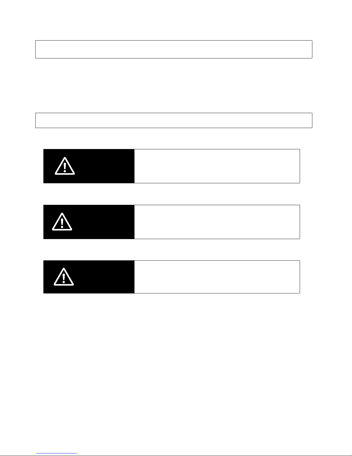
Safety Precautions
Meanings of Signal Words
DANGER
Indicates an imminently hazardous situation which, if
not avoided, is likely to result in serious injury or may
result in death. Additionally there may be severe property damage.
WARNING
Indicates a potentially hazardous situation which, if not
avoided, will result in minor or moderate injury, or may
result in serious injury or death. Additionally there may
be significant property damage.
CAUTION
Indicates a potentially hazardous situation which, if not
avoided, may result in minor or moderate injury or in
property damage.
Page 9
VII
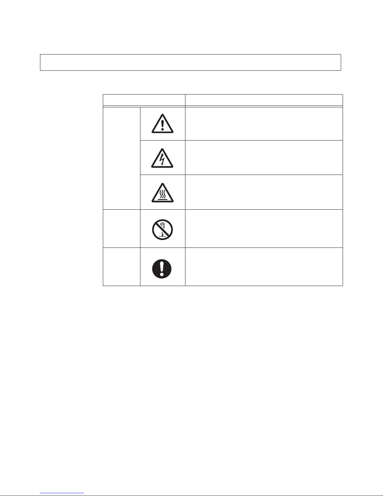
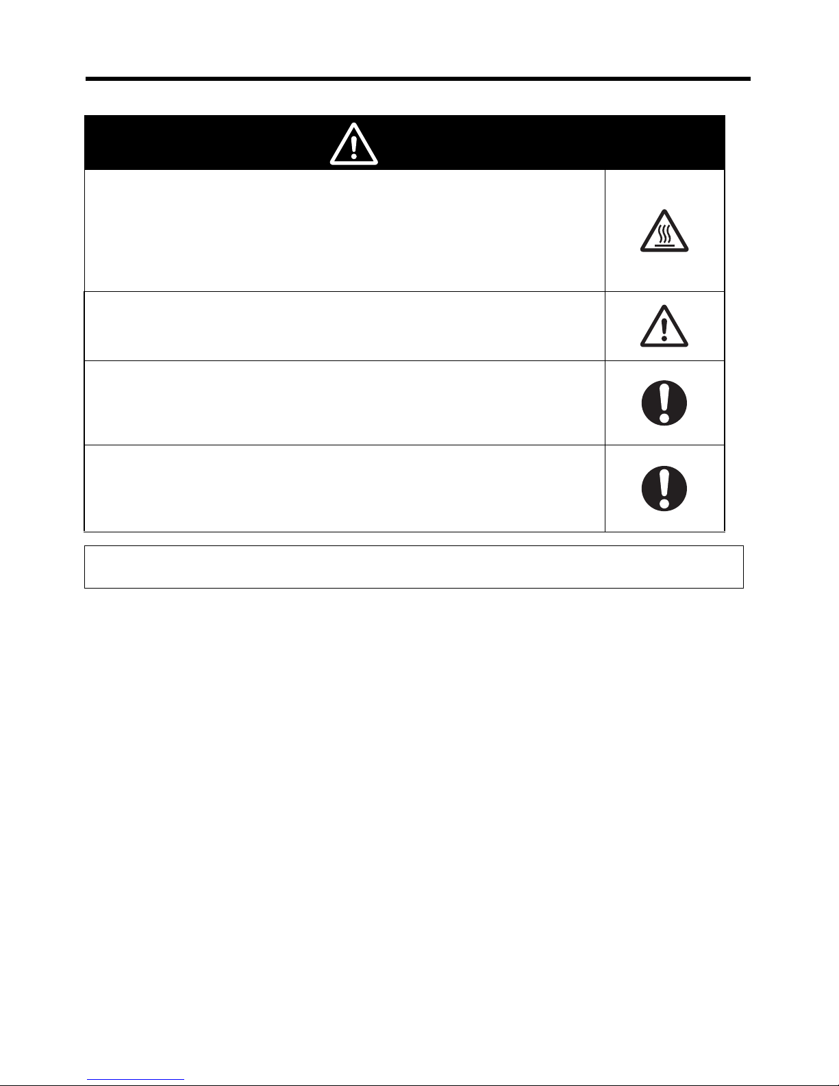
The following alert symbols are used in this manual.
Meanings of Alert Symbols
Symbol Meaning
Caution
General Caution
Indicates non-specific general cautions, warnings, and
dangers.
Electrical Shock Caution
Indicates possibility of electric shock under specific
conditions.
High Temperature Caution
Indicates possibility of burns due to high temperatures
under specific conditions.
Prohibition
Disassembly Prohibition
Indicates prohibitions when there is a possibility of
injury, such as from electric shock, as the result of
disassembly.
Mandatory
Caution
General Caution
Indicates non-specific general cautions, warnings, and
dangers.
Page 10
VIII
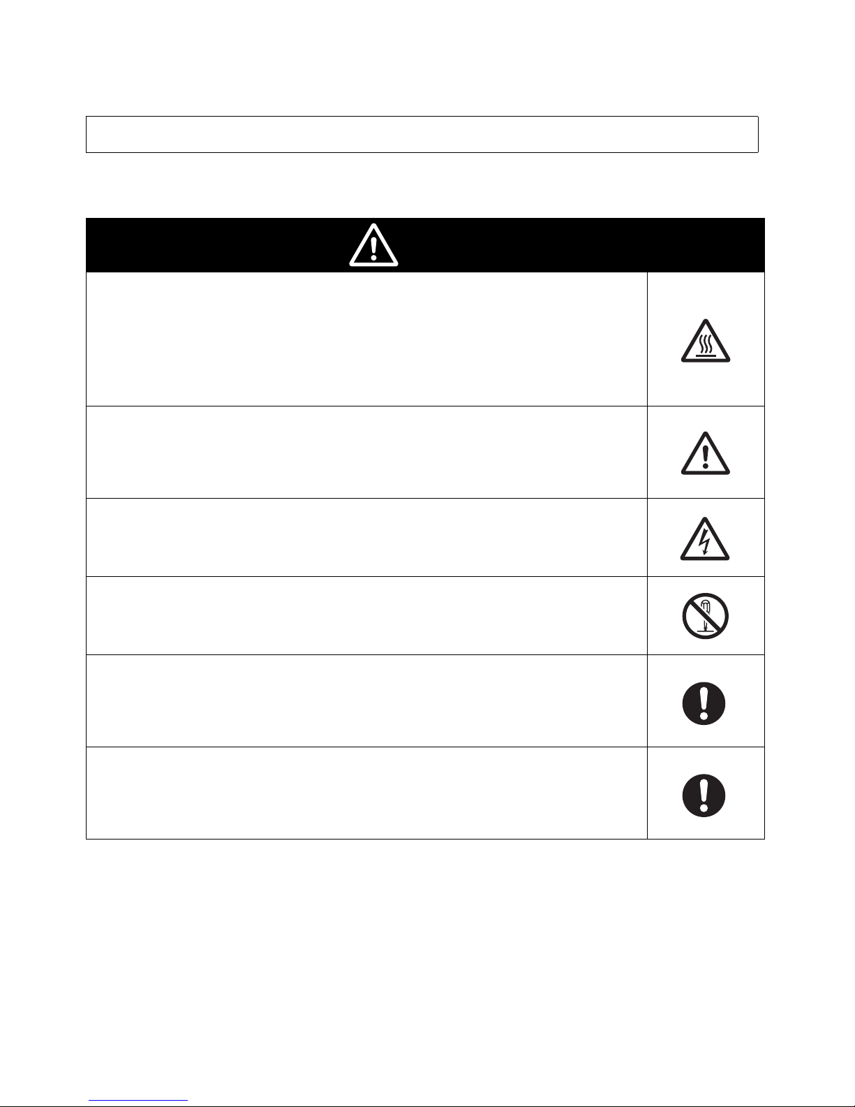
The following alert statements apply to the products in this manual. Each alert statement also
appears at the locations needed in this manual to attract your attention.
Alert Statements in this Manual
Caution
Be sure to use the specified Braking Resistor or Braking Resistor Unit.
Not doing so may occasionally result in moderate burns due to heating of the
Braking Resistor or Braking Resistor Unit.
When using a Braking Resistor or Braking Resistor Unit, be sure to install a
thermal relay to monitor the resistor temperature.
Include a sequence to turn OFF the power supply to the Inverter if the Braking
Resistor or Braking Resistor Unit overheats.
Terminals B1 and B2 are for connecting an optional Braking Resistor or Braking
Resistor Unit. Do not connect any device other than a Braking Resistor or Braking Resistor Unit to these terminals.
Doing so may occasionally result in moderate fire, heating, or equipment damage.
Do not open terminal covers while the power is being supplied or for at least
one minute after the power has been turned OFF.
Doing so may occasionally result in minor injury from electrical shock.
Do not remove the fan cover except when replacing the fan. Before replacing
the fan, first turn OFF the power and disconnect the wiring.
Doing so may occasionally result in minor injury from electrical shock.
Install external breakers (MCCB) suitable for the Inverter capacity on the power
supply side of the Inverter and take other safety measures against short-circuiting in load wiring.
Not doing so may occasionally result in property damage from short-circuiting
in load wiring.
Cover the Inverter or take other measures to prevent filings or lead clippings
from entering the Inverter during installation and wiring.
The Inverter contains high-voltage components and Inverter damage or property damage may occasionally occur if the high-voltage components are shortcircuited.
Page 11

IX
■ Installation and Storage Environment
• Do not store, install, or operate the product in any of the following locations.
• Locations subject to direct sunlight.
• Locations subject to temperatures outside the range specified in the specifications.
• Locations subject to humidity outside the range specified in the specifications.
• Locations subject to condensation resulting from severe changes in temperature.
• Locations subject to corrosive or flammable gases.
• Locations subject to exposure to combustibles.
• Locations subject to dust (especially iron dust) or salts.
• Locations subject to exposure to water, oil, or chemicals.
• Locations subject to shock or vibration.
■
Transporting, Installation, and Wiring
• Always use the original shipping box when transporting the Inverter.
• Do not apply excessive shock to the Inverter or drop the Inverter. The Inverter may malfunction
or may be damaged.
• Do not connect an AC power supply voltage to the U, V, and W output terminals. Doing so will
damage the Inverter.
• Do not connect any load other than a three-phase inductive motor to the U, V, and W output
terminals.
• Do not connect an AC power supply voltage to the control I/O terminals. Doing so will damage
the Inverter.
• Use 600-V polyvinyl chloride (PVC) cable with a wire size of 0.75 to 2 mm
2
to wire the main
circuit terminals. Also, tighten the terminal screws on the terminal block to a torque of 0.8 to
1.0 N·m.
• Take appropriate and sufficient shielding countermeasures when installing systems in the following locations. Not doing so may result in malfunction or equipment damage.
• Locations subject to static electricity or other forms of noise.
• Locations subject to strong electromagnetic fields and magnetic fields.
• Locations close to power lines.
■
Operation and Maintenance
• This Inverter can be set to operate from low speed to high speed. Operate the Inverter only
after sufficiently confirming the allowable range for the motor installation being used.
• Take measures to assure safety before performing maintenance or inspection, or replacing
components.
Precautions for Safe Use
Page 12

X
■ Installation
• Mount the product vertically on a wall or on a DIN Track. Leave the prescribed space between
this product and the control panel surface and other devices.
■ Main Circuit Power Supply
• Use a three-phase, 200 to 230 V, 50/60 Hz power supply.
■ Operation after Power Interruptions
• If continuing operation is selected for the momentary power interruption restart selection parameter (P09), the system may unexpectedly start operation after a momentary power interruption is reset. Exercise suitable caution.
■ Operation Command Selection
• If the operation command selection parameter (P10) is set to “PLC” to enable using the control
circuit terminal inputs (STF and STR), the motor may start operation when the power supply
is turned ON or an alarm is reset if the control circuit terminals are left ON. Exercise suitable
caution. Also, if signals are checked during operation and a voltage is incorrectly applied to the
control circuit terminals, the motor may start moving unexpectedly. Always check safety before
performing signal checks.
■ Motor Overheating Protection (Electronic Thermal)
• The Inverter uses an electronic thermal to protect the motor from overheating. Set the rated
current of the motor in the rated motor current parameter (P01). If more than one motor is operated with one Inverter, set the rated motor current parameter (P01) to 0.0 to disable motor
overload detection, and install a thermal relay between the Inverter and each motor. Set the
thermal relay to the nameplate current at 50 Hz and to 1.1 times the nameplate current at 60
Hz.
■ Disposing of the Inverter
• Observe all applicable legal requirements when disposing of the Inverter.
Precautions for Correct Use
Page 13

XI
■ Warning Label Position
• A warning label is pasted on the product as shown in the following illustration.
Be sure to follow the instructions given there.
■ Contents of Warning
Warning label
Front panel
Page 14
XII
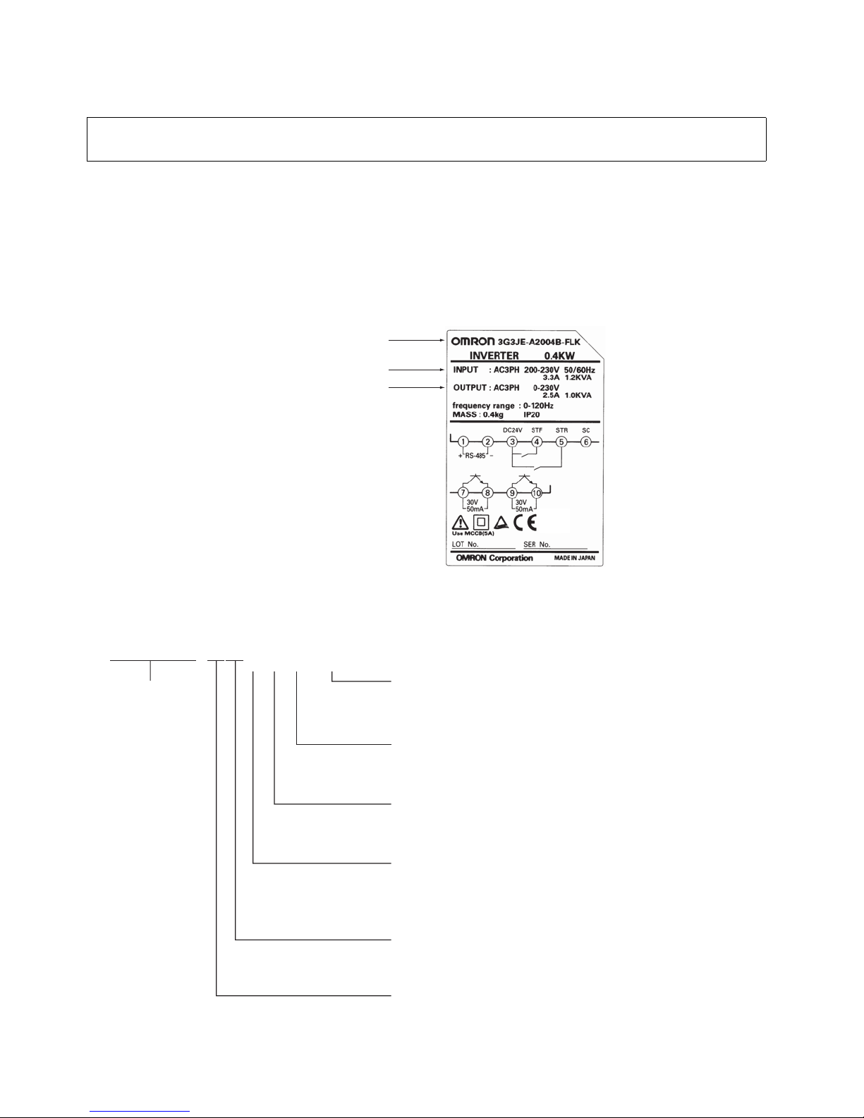
■ Checking the Product
On delivery, always check that the delivered product is the 3G3JE Inverter that you ordered.
Should you find any problems with the product, immediately contact your nearest local sales representative.
● Checking the Nameplate
● Checking the Model
Checking Before Unpacking
Inverter model
Input specifications
Output specifications
Series name
3G3JE Series
Voltage Class
2: Three-phase 200 V AC
Degree of Protection
A: Panel-mountin
g (
IP10 or higher)/Closed wall-mountin
g
(1) (2) (3) (4)
3G3JE−A2@@@−@
(4) Communications
Blank: No communications function
FLK: CompoWay/F
(3) Control Circuit Terminals (Input Side)
Blank: PNP input
N: NPN input
(2) Braking Resistor Control
Blank: No Braking Resistor control.
B: Braking Resistor control provided.
(1) Maximum Applicable Motor Capacity
001: 0.1 kW
002: 0.2 kW
004: 0.4 kW
Page 15

XIII
■ Checking the Accessories
An Instruction Manual is the only accessory provided with the 3G3JE. Set screws and other necessary parts must be provided by the user.
Page 16

XIV
About this Manual
This manual is divided into the chapters described in the following table. Understanding how information is organized will enable you to use the manual more efficiently.
Chapter Contents
Chapter 1
Overview
Describes Inverter features and nomenclature.
Chapter 2
Design
Provides dimensions, installation methods, peripheral device design
information, and peripheral device selection information.
Chapter 3
Operation
Describes initial setting methods, operation confirmation methods,
and functions.
Chapter 4
Maintenance Operations
Describes Inverter maintenance.
Provides troubleshooting information for when errors occur in the
Inverter and periodic inspection and maintenance information.
Chapter 5
Specifications
Provides Inverter specifications, as well as the specifications and
dimensions of peripheral devices.
Chapter 6
Parameter Tables
Provides tables of basic information on Inverter parameters in RUN
Mode, Adjustment Mode, and Initial Settings Mode as a reference for
users already familiar with Inverter operation. Use this chapter when
adjusting the Inverter.
Parameters are listed with the page numbers of further information for
easy reference.
Chapter 7
Appendix
Provides information on selecting the Inverter and precautions on
using the Inverter for a motor.
Page 17

Table of Contents
XV
Chapter 1. Overview . . . . . . . . . . . . . . . . . . . . . . . . . . . . . . . . . . . . . . 1-1
1-1 Functions . . . . . . . . . . . . . . . . . . . . . . . . . . . . . . . . . . . . . . . . . . . . . . . . . . . . . . . . . . . . . . . . 1-2
1-2 Nomenclature . . . . . . . . . . . . . . . . . . . . . . . . . . . . . . . . . . . . . . . . . . . . . . . . . . . . . . . . . . . . . 1-3
Chapter 2. Design. . . . . . . . . . . . . . . . . . . . . . . . . . . . . . . . . . . . . . . . . 2-1
2-1 Installation . . . . . . . . . . . . . . . . . . . . . . . . . . . . . . . . . . . . . . . . . . . . . . . . . . . . . . . . . . . . . . . 2-4
2-2 Wiring. . . . . . . . . . . . . . . . . . . . . . . . . . . . . . . . . . . . . . . . . . . . . . . . . . . . . . . . . . . . . . . . . . . 2-6
Chapter 3. Operation. . . . . . . . . . . . . . . . . . . . . . . . . . . . . . . . . . . . . . 3-1
3-1 Key Operation Flowchart . . . . . . . . . . . . . . . . . . . . . . . . . . . . . . . . . . . . . . . . . . . . . . . . . . . . 3-3
3-2 Procedure for Test Run . . . . . . . . . . . . . . . . . . . . . . . . . . . . . . . . . . . . . . . . . . . . . . . . . . . . . . 3-4
3-3 Performing a Test Run . . . . . . . . . . . . . . . . . . . . . . . . . . . . . . . . . . . . . . . . . . . . . . . . . . . . . . 3-5
3-4 RUN Mode . . . . . . . . . . . . . . . . . . . . . . . . . . . . . . . . . . . . . . . . . . . . . . . . . . . . . . . . . . . . . . . 3-9
3-5 Adjustment Mode . . . . . . . . . . . . . . . . . . . . . . . . . . . . . . . . . . . . . . . . . . . . . . . . . . . . . . . . . . 3-12
3-6 Initial Settings Mode . . . . . . . . . . . . . . . . . . . . . . . . . . . . . . . . . . . . . . . . . . . . . . . . . . . . . . . 3-17
Chapter 4. Maintenance Operations . . . . . . . . . . . . . . . . . . . . . . . . . 4-1
4-1 Protective and Diagnostic Functions . . . . . . . . . . . . . . . . . . . . . . . . . . . . . . . . . . . . . . . . . . . 4-3
4-2 Troubleshooting . . . . . . . . . . . . . . . . . . . . . . . . . . . . . . . . . . . . . . . . . . . . . . . . . . . . . . . . . . . 4-7
4-3 Maintenance and Inspection. . . . . . . . . . . . . . . . . . . . . . . . . . . . . . . . . . . . . . . . . . . . . . . . . .4-12
Chapter 5. Specifications. . . . . . . . . . . . . . . . . . . . . . . . . . . . . . . . . . . 5-1
5-1 Inverter Specifications . . . . . . . . . . . . . . . . . . . . . . . . . . . . . . . . . . . . . . . . . . . . . . . . . . . . . . 5-2
5-2 Option Specifications . . . . . . . . . . . . . . . . . . . . . . . . . . . . . . . . . . . . . . . . . . . . . . . . . . . . . . . 5-4
Chapter 6. Parameter Tables . . . . . . . . . . . . . . . . . . . . . . . . . . . . . . . 6-1
Chapter 7. Appendix . . . . . . . . . . . . . . . . . . . . . . . . . . . . . . . . . . . . . . 7-1
7-1 Selecting the Inverter . . . . . . . . . . . . . . . . . . . . . . . . . . . . . . . . . . . . . . . . . . . . . . . . . . . . . . . 7-2
7-2 Precautions on Using the Inverter for a Motor . . . . . . . . . . . . . . . . . . . . . . . . . . . . . . . . . . . . 7-9
Revision History . . . . . . . . . . . . . . . . . . . . . . . . . . . . . . . . . . . . . . . . . . R-1
Page 18

Table of Contents
XVI
Page 19

Chapter 1
Overview
1-1 Functions
1-2 Nomenclature
Page 20

Chapter 1
1-2
Overview
1-1 Functions
■ 3G3JE Models
• Rated power supply voltage: Three-phase 200 to 230 V AC
• Enclosure rating: IP20
(1) Models with PNP Input
(2) Models with NPN Input
■ Conformance with International Standards
■ Convenient Functions for Easy Operation
• Easy torque adjustment according to load torque characteristics.
• Replaceable cooling fan.
• Standard models include an interface for connecting to time-shared proportional pulse output,
enabling direct connection to digital controllers or temperature controllers.
• Models with RS-485 communications support the CompoWay/F OMRON communications protocol.
Maximum applicable motor capacity 0.1 kW 0.2 kW 0.4 kW
No braking resistor control
Standard models
4 inputs and 2 outputs
3G3JE-A2001 3G3JE-A2002 3G3JE-A2004
RS-485 communications models
2 inputs and 2 outputs
3G3JE-A2001-FLK --- ---
Braking resistor
control
Standard models
4 inputs and 2 outputs
--- 3G3JE-A2002B 3G3JE-A2004B
RS-485 communications models
2 inputs and 2 outputs
--- 3G3JE-A2002B-FLK 3G3JE-A2004B-FLK
Maximum applicable motor capacity 0.1 kW 0.2 kW 0.4 kW
No braking resistor control
Standard models
4 inputs and 2 outputs
3G3JE-A2001N 3G3JE-A2002N 3G3JE-A2004N
RS-485 communications models
2 inputs and 2 outputs
3G3JE-A2001NFLK
--- ---
Braking resistor
control
Standard models
4 inputs and 2 outputs
--- 3G3JE-A2002BN 3G3JE-A2004BN
RS-485 communications models
2 inputs and 2 outputs
--- 3G3JE-A2002BNFLK
3G3JE-A2004BNFLK
Classification Applicable standard
EC Directives EMC Directive EN 61800-3
Low-voltage Directive EN 61800-5-1 (Pollution Degree 2/Overvoltage Category II)
Page 21
Chapter 1
1-3
Overview
1-2 Nomenclature
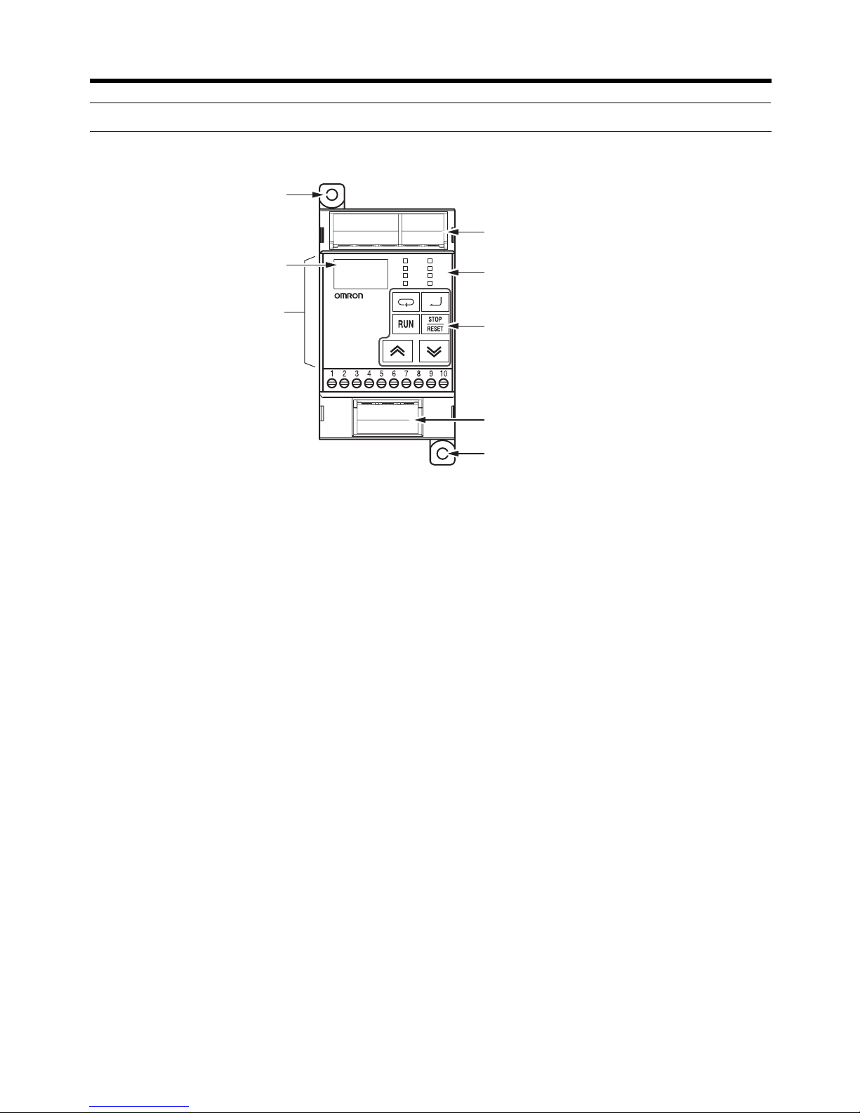
■ Part Names
Hz set
Hz out
A
Kh
RUN
RVS
ALM
COM
EasySpeed
3G3JE INVERT ER
8.8.8
3-Phase
AC power supply
B1 B2
Braking
resistor
R/L1 S/L2 T/L3
Motor
U/T1 V/T2 W/T3
Mounting hole
Digital Operator
Terminal block
cover
Data display
Simplified-LED
indicators
Operation keys
Terminal block
cover
Mounting hole
Page 22
Chapter 1
1-4
Overview
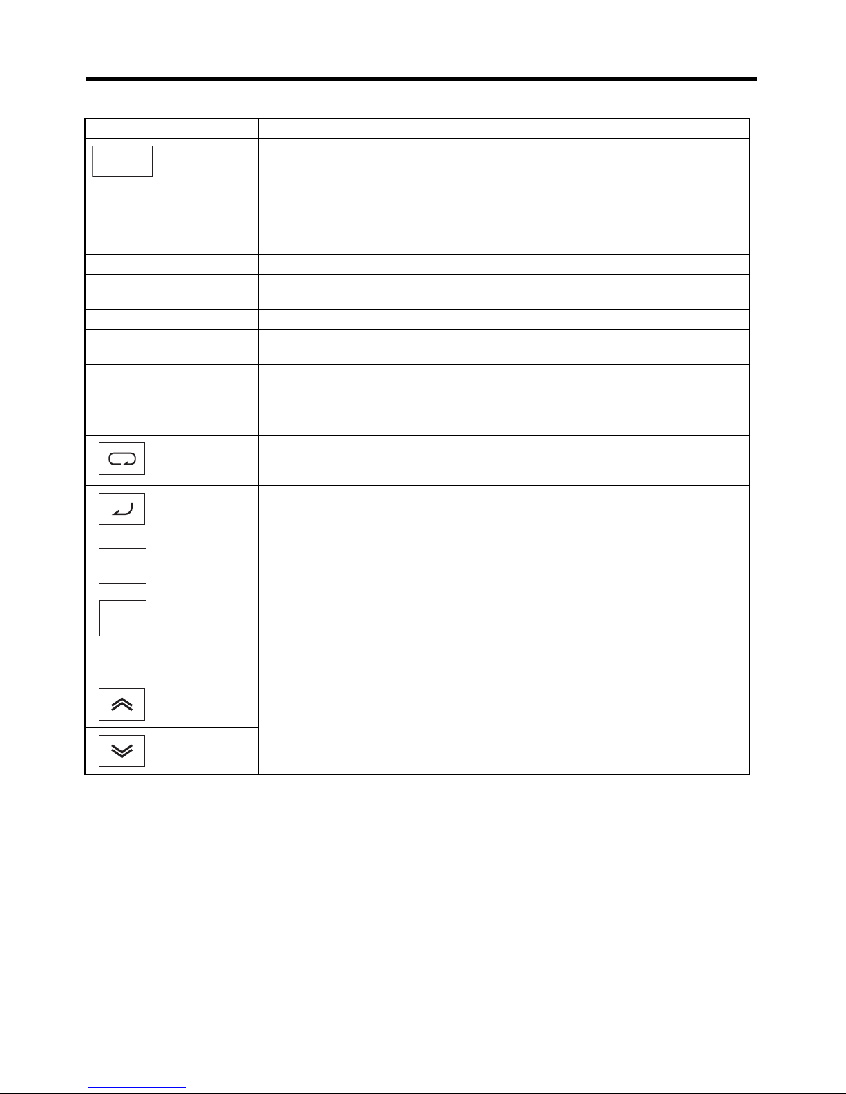
■ Digital Operator Part Names
Note Refer to Section 3 Operation for information on moving between modes.
Name Function
Data display Displays relevant data, such as the frequency reference, output frequency, out-
put current, parameter set values, and accumulated operating time.
@ Hz set Frequency ref-
erence
Lit when the data display shows the frequency reference.
@ Hz out Output fre-
quency
Lit when the data display shows the output frequency.
@ A Output current Lit when the data display shows the output current.
@ Kh Accumulated
operating time
Lit when the data display shows the accumulated operating time.
@ RUN RUN indicator Lit while the Inverter is operating.
@ RVS Reverse oper-
ation indicator
Lit while the Inverter is operating in reverse.
@ ALM Alarm indica-
tor
Lit when a fault is detected or a protective function has been triggered. (Error
information can be monitored in RUN mode.)
@ COM Communica-
tions indicator
Lit while data is being sent or received. (Communications models only.)
Mode Key In RUN mode, switches the setting/monitoring indicators. When pressed for one
second or longer, the mode changes from the RUN mode to the initial settings
mode.
Enter Key Enters displayed items, set values, etc.
When this key is pressed for one second or longer, the mode is changed from
RUN mode to adjustment mode.
RUN Key Starts the Inverter if operation with the Digital Operator is selected.
STOP/RESET
Key
Stops the Inverter.
This key also clears errors when errors are detected or a protection function
operates.
Operating with the Digital Operator must be selected to use the above key func-
tions.
Increment Key These keys change the displayed set value. They also change the parameter
set in the adjustment mode or initial settings mode.
Decrement
Key
888
RUN
STOP
RESET
Page 23

Chapter 2
Design
2-1 Installation
2-2 Wiring
Page 24
Chapter 2
2-2
Design
■ Installation and Storage Environment
• Do not store, install, or operate the product in any of the following locations.
• Locations subject to direct sunlight.
• Locations subject to temperatures outside the range specified in the specifications.
• Locations subject to humidity outside the range specified in the specifications.
• Locations subject to condensation resulting from severe changes in temperature.
• Locations subject to corrosive or flammable gases.
• Locations subject to exposure to combustibles.
• Locations subject to dust (especially iron dust) or salts.
• Locations subject to exposure to water, oil, or chemicals.
• Locations subject to shock or vibration.
Caution
Be sure to use the specified Braking Resistor or Braking Resistor Unit.
Not doing so may occasionally result in moderate burns due to heating of the Braking
Resistor or Braking Resistor Unit.
When using a Braking Resistor or Braking Resistor Unit, be sure to install a thermal
relay to monitor the resistor temperature.
Include a sequence to turn OFF the power supply to the Inverter if the Braking Resis-
tor or Braking Resistor Unit overheats.
Terminals B1 and B2 are for connecting an optional Braking Resistor or Braking
Resistor Unit. Do not connect any device other than a Braking Resistor or Braking
Resistor Unit to these terminals.
Doing so may occasionally result in moderate fire, heating, or equipment damage.
Install external breakers (MCCB) suitable for the Inverter capacity on the power sup-
ply side of the Inverter and take other safety measures against short-circuiting in load
wiring.
Not doing so may occasionally result in property damage from short-circuiting in load
wiring.
Cover the Inverter or take other measures to prevent filings or lead clippings from
entering the Inverter during installation and wiring.
The Inverter contains high-voltage components and Inverter damage or property
damage may
occasionally occur if the high-voltage components are short-cir-
cuited.
Precautions for Safe Use
Page 25

Chapter 2
2-3
Design
■ Transporting, Installation, and Wiring
• Always use the original shipping box when transporting the Inverter.
• Do not apply excessive shock to the Inverter or drop the Inverter. The Inverter may malfunction
or may be damaged.
• Do not connect an AC power supply voltage to the U, V, and W output terminals. Doing so will
damage the Inverter.
• Do not connect any load other than a three-phase inductive motor to the U, V, and W output
terminals.
• Do not connect an AC power supply voltage to the control I/O terminals. Doing so will damage
the Inverter.
• Use 600-V polyvinyl chloride (PVC) cable with a wire size of 0.75 to 2 mm
2
to wire the main
circuit terminals. Also, tighten the terminal screws on the terminal block to a torque of 0.8 to
1.0 N·m.
• Take appropriate and sufficient shielding countermeasures when installing systems in the following locations. Not doing so may result in malfunction or equipment damage.
• Locations subject to static electricity or other forms of noise.
• Locations subject to strong electromagnetic fields and magnetic fields.
• Locations close to power lines.
■
Installation
• Mount the product vertically on a wall or on a DIN Track. Leave the prescribed space between
this product and the control panel surface and other devices.
■ Main Circuit Power Supply
• Use a three-phase, 200 to 230 V, 50/60 Hz power supply.
Precautions for Correct Use
Page 26
Chapter 2
2-4
Design
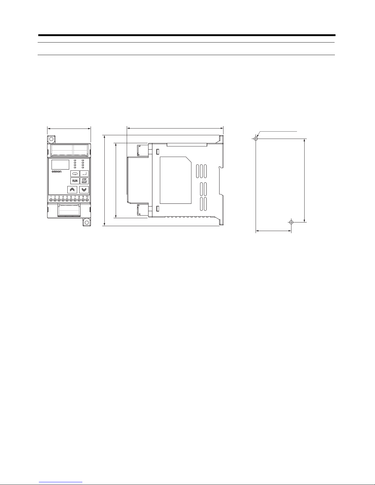
2-1 Installation
2-1-1 Dimensions
● 3G3JE-A2001/-A2002/-A2004: Three-phase 200-V AC Input
Note All models are the same size.
2-1-2 Installation Conditions
■ Installation Direction
• Screw the Inverter to a wall or mount it to DIN Track so that the characters on the nameplate read
normally when facing the Inverter in a normal vertical position.
■ Clearances from Peripheral Devices
• When installing the Inverter, always provide the following clearances to allow normal heat dissipation from the Inverter. If using a line of 0.1-kW Inverters, leave ample space at the top of each one
to allow airflow.
Hz set
Hz out
A
Kh
RUN
RVS
ALM
COM
EasySpeed
3G3JE INVERTER
55
3-Phase
AC power supply
B1 B2
Braking
resistor
R/L1 S/L2 T/L3
Motor
U/T1 V/T2 W/T3
115
95
123.3
(including 0.3 for height of raised characters)
45
106
4.5 dia. or M4
(
Unit: mm
)
Panel Mounting Dimensions
Page 27

Chapter 2
2-5
Design
• Side-by-side mounting is possible as long as the ambient temperature is −10 to 45°C. (All models)
Inverter capacity Model W (clearance: −10 to 50°C)
0.1 kW 3G3JE-A2001 3G3JE-A2001N 10 mm
3G3JE-A2001-FLK 3G3JE-A2001N-FLK
0.2 kW 3G3JE-A2002 3G3JE-A2002N 10 mm
3G3JE-A2002B 3G3JE-A2002BN
3G3JE-A2002B-FLK 3G3JE-A2002BN-FLK
0.4 kW 3G3JE-A2004 3G3JE-A2004N 10 mm
3G3JE-A2004B 3G3JE-A2004BN
3G3JE-A2004B-FLK 3G3JE-A2004BN-FLK
WW W
100 mm min.
100 mm min.
Air
Air
Inverter Inverter Inverter
Side
100 mm min.
100 mm min.
Air
Air
Inverter Inverter Inverter
Side
W
Page 28
Chapter 2
2-6
Design
2-2 Wiring
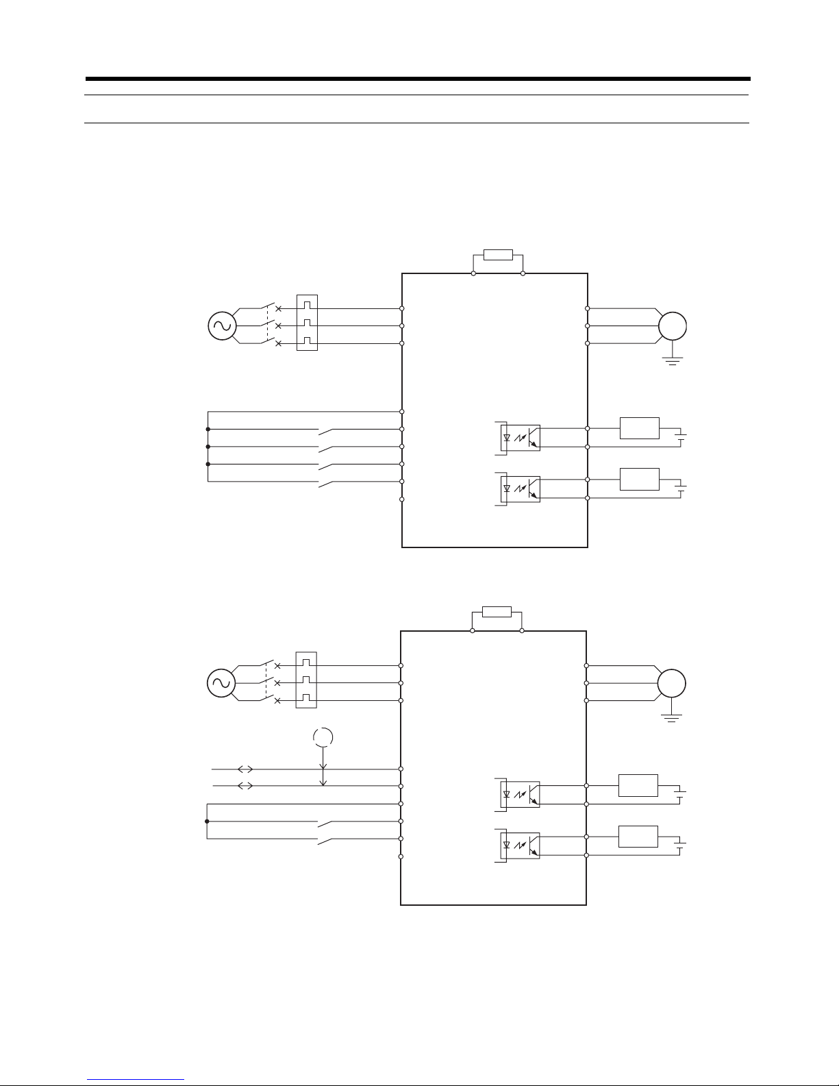
2-2-1 Standard Connection Diagrams
■ Standard Models
■ Communications Models
Note 1. Refer to 2-2-4 Wiring Control Circuit Terminals for information on wiring the control circuit
terminals.
2. An optional Braking Resistor can be connected only to Inverters with braking resistor control.
Forward/stop
Reverse/stop
R/L1
B1 B2
S/L2
T/L3
24 VDC/SC (See note 1.)
U/T1
V/T2
W/T3
Braking Resistor (option) (See note 2.)
SS0
SS1
STF
STR
SC/24 VDC
Load
Load
1
2
3
4
5
6
ALM (+)
ALM (−)
STA (+)
STA (−)
7
8
9
10
Multi-step speed reference 0
3G3JE
Inverter
Three-phase
200 to 230 V AC
M
3~
MCCB
Multi-step speed reference 1
R/L1
B1 B2
S/L2
T/L3
U/T1
V/T2
W/T3
Load
Load
Forward/stop
Reverse/stop
1
2
3
4
5
6
7
8
9
10
3G3JE
Inverter
MCCB
Three-phase
200 to 230 V AC
RS-485 (+)
RS-485 (−)
RS-485 (+)
RS-485 (−)
24 VDC/SC (See note 1.)
STF
STR
SC/24 VDC
ALM (+)
ALM (−)
STA (+)
STA (−)
Braking Resistor (option) (See note 2.)
M
3~
Page 29
Chapter 2
2-7
Design
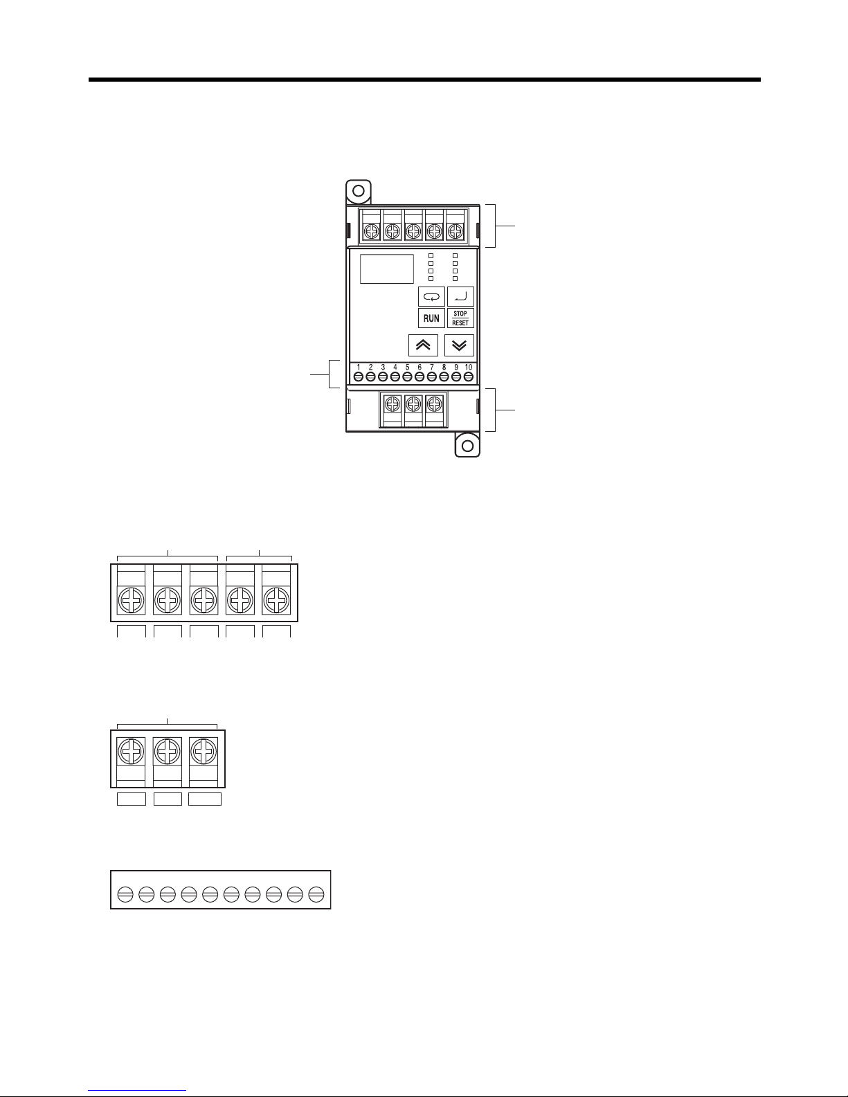
2-2-2 Terminal Block
■ Terminal Arrangement
■ Arrangement of Main Circuit Input Terminals
■ Arrangement of Main Circuit Output Terminals
■ Control Circuit Terminals
Hz set
Hz out
A
Kh
RUN
RVS
ALM
COM
888
OMRON
EasySpeed
3G3JE INVERTER
Main circuit input terminals
Main circuit output terminals
Control circuit terminals
R/L1 S/L2 T/L3 B1 B2
Power supply input
Braking Resistor
connection
U/T1 V/T2 W/T3
Motor output
1 2 3 4 5 6 7 8 9 10
Page 30

Chapter 2
2-8
Design
■ Terminal Arrangement for Standard Models
■ Terminal Arrangement for Models with Communications
■ Main Circuit Terminals
■ Control Circuit Terminals for Standard Models
Terminal123456 7 8 910
Models with
PNP input
24
VDC
SS0 SS1 STF STR SC ALM (+) ALM (
−) S TA (+ ) S TA (−)
Models with
NPN input
(@@@@N)
SC SS0 SS1 STF STR 24
VDC
ALM (+) ALM (
−) S TA (+ ) S TA (−)
Terminal123456 7 8 910
Models with
PNP input
RS-485
(+)
RS-485
(
−)
24
VDC
STF STR SC ALM (+) ALM (
−) S TA (+ ) S TA (−)
Models with
NPN input
(@@@@N)
RS-485
(+)
RS-485
(
−)
SC STF STR 24
VDC
ALM (+) ALM (
−) S TA (+ ) S TA (−)
Symbol Name Description
R/L1 Power supply inputs Inputs for connecting three-phase 200 to 230-V AC power sup-
ply.
S/L2
T/L3
U/T1 Motor outputs Three-phase power supply outputs for driving the motor.
V/T2
W/T3
B1 Between B1 and B2: Braking
Resistor connection terminals
Connect between B1 and B2 to connect a Braking Resistor or a
Braking Resistor Unit. (3G3JE-A2@@@B models with braking
resistor control only)
B2
Symbol Name Function Specifications
Input 24VDC Internal 24-V power sup-
ply
The 24-VDC power supply input for
Inverter control circuits. Do not use this
power supply for any other purpose.
Photocoupler
(24 V DC, 5 mA
per input)
SS0 Multi-step speed refer-
ence 0
Executes multi-step speed reference in
combination with SS0 and SS1 when
P11 (Frequency reference selection) is
set to MSP (multi-step speed reference). (See note.)
SS1 Multi-step speed refer-
ence 1
STF Forward/stop command Executes forward operation.
STR Reverse/stop command Executes reverse operation.
SC External power supply
common
Common terminal for when internal
24-V power supply is not used.
Output ALM (+) Alarm output Turns ON when an alarm occurs. Open collector
(30 V DC, 50 mA
max.)
ALM (
−)
STA (+) Multi-function output Turns ON when the operating status
selected in P12 (Multi-function output
selection) is reached.
STA (
−)
Page 31

Chapter 2
2-9
Design
Note If P11 (Frequency reference selection) is set to T.C (Temperature controller time-shared pro-
portional pulses), multi-step speed reference 0 (SS0) will be the temperature controller timeproportional pulse input and multi-step speed reference 1 (SS1) will be ignored.
■ Control Circuit Terminals for Communications Models
● Relation between Control Circuit Terminals and Frequency Reference
Multi-step speed reference 0 (SS0) and multi-step speed reference 1 (SS1) can be used together to
select one of the following frequency references.
Note Multi-step speed references are supported only for Standard Models.
● Relation between Control Circuit Terminals and Forward/Reverse Commands
The operation commands from control input are as follows:
Symbol Name Function Specifications
Input RS-485 (+) RS-485 communications
terminals
Refer to the separate Communications Manual for communications specifications, wiring, communications commands, and other related information.
RS-485 (
−)
24 VDC Internal 24-V power sup-
ply
The 24-VDC power supply input for
Inverter control circuits. Do not use this
power supply for any other purpose.
Photocoupler
(24 V DC, 5 mA per
input)
STF Forward/stop command Executes forward operation.
STR Reverse/stop command Executes reverse operation.
SC External power supply
common
Common terminal for when internal 24V power supply is not used.
Output ALM (+) Alarm output Turns ON when an alarm occurs. Open collector
(30 V DC, 50 mA
max.)
ALM (
−)
STA (+) Multi-function output Turns ON when the operating status
selected in P12 (Multi-function output
selection) is reached.
STA (
−)
Multi-step speed reference SS0 SS1
Frequency reference 1 (SP1) OFF OFF
Frequency reference 2 (SP2) ON OFF
Frequency reference 3 (SP3) OFF ON
Frequency reference 4 (SP4) ON ON
Operation Command STF STR
Stop OFF OFF
Forward ON OFF
Reverse OFF ON
Stop ON ON
Page 32

Chapter 2
2-10
Design
2-2-3 Main Circuit Terminal Wiring
■ Main Circuit Terminal Connections
• Use insulated wiring with a rated voltage of 600 V and a temperature rating of 80°C min. for main
circuit terminals.
• For terminal connections, use crimp terminals with insulating sleeves.
• When not connecting a Braking Resistor or a Braking Resistor Unit, screw crimp terminals with
insulating sleeves to the Inverter's braking resistance connection terminals.
• Up to two power lines can be connected per terminal.
• If there is a possibility of voltage drops, increase the wire size according to the cable length.
● Wire Sizes, Terminal Screws, Screw Tightening Torque, and Molded-case Circuit
Breaker (MCCB) Capacities
■ Main Circuit Connection Diagram
■ Wiring the Input Side of the Main Circuit
● Installing Molded-case Circuit Breakers
• Always install molded-case circuit breakers (MCCBs) in the power supply wiring to protect against short-circuit accidents.
• Always connect the power input terminals (R/L1, S/L2, and T/L3) and power supply via an MCCB suitable to
the Inverter.
• Install one MCCB per Inverter.
• Choose an MCCB with the capacity indicated in the previous tables (Wire Size, Terminal Screw,
Tightening Torque, and Molded-case Circuit Breaker Capacities).
Model Terminal symbol Terminal
screw
Screw
tightening
torque (N·m)
Wire size
(mm
2
)
Recom-
mended wire
size (mm
2
)
MCCB
capacity
(A)
3G3JE-A2001 R/L1, S/L2, T/L3, B1, B2,
U/T1, V/T2, W/T3
M3.5 0.8 to 1.0 0.75 to 2 2 3 to 5
3G3JE-A2002 R/L1, S/L2, T/L3, B1, B2,
U/T1, V/T2, W/T3
M3.5 0.8 to 1.0 0.75 to 2 2 3 to 5
3G3JE-A2004 R/L1, S/L2, T/L3, B1, B2,
U/T1, V/T2, W/T3
M3.5 0.8 to 1.0 0.75 to 2 2 5
R/L1
S/L2
T/L3
U/T1
V/T2
W/T3
3G3JE
Inverter
M
3~
MCCB
B1 B2
Braking Resistor (option)
Three-phase
200 to 230 V AC
Page 33

Chapter 2
2-11
Design
• For the MCCB's time characteristics, be sure to consider the Inverter's overcurrent protection (one
minute at 150% of the rated output current).
• A sequence that turns OFF the power supply using the alarm (ALM) output of the 3G3JE can be
made as shown in the following diagram.
● Installing a Ground Fault Interrupter
• Inverter outputs use high-speed switching, so high-frequency leakage current is generated. (In general, a leakage current of approximately 100 mA will occur for each Inverter when the power cable
is 1 m and approximately 5 mA for each additional meter of power cable.)
• Use a separate breaker for the power supply input section of the Inverter that removes high-frequency leakage currents and detects only leakage currents with frequencies hazardous to human
beings. Use a breaker with a sensitivity amperage of at least 10 mA per Inverter.
• When using a general leakage breaker, choose a ground fault interrupter with a sensitivity amperage of 200 mA or more per Inverter and with an operating time of 0.1 s or more.
● Installing a Magnetic Contactor
• If the power supply of the main circuit is to be turned OFF because of the sequence, a magnetic
contactor (MC) can be used. (When a magnetic contactor is installed on the primary side of the
main circuit to forcibly stop a load, however, the regenerative braking will not work and the load will
coast to a stop.)
• A load can be started and stopped by switching the magnetic contactor. Frequently switching the
magnetic contactor, however, may cause the Inverter to break down. To maintain the service life of
the Inverter's internal electrolytic capacitors, it is recommended that the MC be switched to start/
stop operation no more than once every 30 minutes.
• When the Inverter is operated with the Digital Operator, automatic operation cannot be performed
after recovery from a power interruption.
● Connecting Input Power Supply to the Terminal Block
Input power supply can be connected to any terminal on the terminal block because the phase
sequence of input power supply is irrelevant to the phase sequence (R/L1, S/L2, and T/L3).
R/L1
S/L2
T/L3
X1
X2
ONOFF
3G3JE
Inverter
ALM (+)
ALM (−)
Three-phase
200 to 230 V AC
X1
X1
X2
MCCB
(30 VDC, 50 mA max.)
DC (24 V) relay
Page 34

Chapter 2
2-12
Design
● Installing an AC Reactor
If the Inverter is connected to a large-capacity power transformer (660 kVA or more) or the phase
advance capacitor is switched, an excessive peak current may flow through the input power circuit,
causing the converter unit to break down. To prevent this, install an optional AC reactor on the input
side of the Inverter. This also improves the power factor on the power supply side.
● Installing a Surge Absorber
Always use a surge absorber or diode for the inductive loads near the Inverter. These inductive loads
include magnetic contactors, electromagnetic relays, solenoid valves, solenoid, and magnetic
brakes.
● Connecting a Braking Resistor or a Braking Resistor Unit
When driving a vertical axis or a load with a large inertia, regenerative energy is returned to the
Inverter.
If main circuit overvoltage (E05) is generated during deceleration, the regenerative energy will
exceed the Inverter's capacity. If this occurs, use a Braking Resistor or a Braking Resistor Unit.
• Connect the Braking Resistor as shown in the following diagram.
• When using a Braking Resistor, be sure to install a thermal relay to monitor the resistor temperature.
• Include a sequence to turn OFF the power supply to the Inverter if the Braking Resistor or
Braking Resistor Unit overheats. Not doing so may result in fire.
• Braking Resistor: Use thermal relay output for temperature monitoring.
• Braking Resistor Unit: Use the Unit's fault contact output.
Braking Resistors and Braking Resistor Units for 200 V-class Inverters
Inverter Braking Resistor
(Usage rate: 3% ED)
Braking Resistor Unit
(Usage rate: 10% ED)
Minimum connection
resistance
3G3JE-A2002 3G3IV-PERF150WJ201
(200
Ω, 150 W)
3G3IV-PLKEB20P7
(200 Ω, 70 W)
200
Ω
3G3JE-A2004
R/L1
S/L2
T/L3
ON
MC
SA
SA
XB
3G3JE
Inverter
Three-phase
200 to 230 V AC
OFF
B1
(1)
(2)
Braking Resistor/
Braking Resistor Unit
MC
XB
(P)
B2
(B)
Braking Unit thermal trip contacts
or external thermal rela
y
contacts
MCCB MC
Page 35

Chapter 2
2-13
Design
• Do not connect a resistance below the minimum. Doing so will damage the Inverter.
• The usage rate is expressed as the percentage of braking time in one cycle. For example, if the cycle time is
10 s and a Braking Resistor Unit with a usage rate of 10% ED is used, braking will be possible for up to 1 s.
● Installing a Noise Filter on the Power Supply Side
• The Inverter's outputs utilize high-speed switching, so noise may be transmitted from the Inverter to
the power line and adversely affect other devices in the vicinity.
• It is recommended that a Noise Filter be installed at the power supply to minimize the noise transmission. (Noise from the power line to the Inverter will also be reduced.)
Recommended Inverter Input-side Noise Filters
Note Noise filters not designed for Inverters are less effective and may not reduce noise.
■ Wiring the Output Side of the Main Circuit Terminals
● Connecting the Terminal Block to the Load
• Connect output terminals U/T1, V/T2, and W/T3 to motor lead wires U, V, and W.
• Check that the motor rotates forward with the forward command. Switch over any two of the output
terminals (U/T1, V/T2, and W/T3) with each other and reconnect if the motor rotates in reverse with
the forward command.
● Never Connect a Power Supply to Output Terminals
If voltage is applied to the output terminals, the internal circuit of the Inverter will be damaged. Never
connect a power supply to output terminals U/T1, V/T2, or W/T3.
● Never Short or Ground Output Terminals
• Do not touch the output terminals with bare hands.
• If the output wires come into contact with the Inverter casing, an electrical shock or grounding will
occur. This is extremely hazardous. Be careful not to short the output wires.
● Do Not Use a Phase Advancing Capacitor or Noise Filter
• Never connect a phase advance capacitor or LC/RC noise filter to the output circuit. Doing so will
result in damage to the Inverter or cause other parts to burn.
General purpose For EMC compliance
3G3EV-PLNFD2103DY 3G3JV-PRS2010J
Inverter input
side
(See note.)
3G3JE
Inverter
M
3~
Three-phase
200 to 230 V AC
MCCB
MCCB
Noise Filter
Other control
device
Page 36

Chapter 2
2-14
Design
● Do Not Use an Electromagnetic Switch of Magnetic Contactor
• If a load is connected to the Inverter during operation, an inrush current will trigger the overcurrent
protective circuit in the Inverter. Do not connect an electromagnetic switch or a magnetic contactor
to the output circuit.
● Installing a Thermal Relay
The Inverter uses an electronic thermal to protect the motor from overheating. Take the following
countermeasures if more than one motor is operated with one Inverter or a multi-polar motor is used.
• Install a thermal relay between the Inverter and each motor and set P01 (Rated motor current) to
0.0. (Motor overload detection (E03) will be disabled.)
• Make a sequence so that the magnetic contactor on the input side of the main circuit is turned OFF
by the contacts of the thermal relay.
● Installing a Noise Filter on the Output Side
Connect a noise filter to the output side of the Inverter to reduce radio noise and induction noise.
Inductive Noise:Electromagnetic induction generates noise on the signal line, causing the controller
to malfunction.
Radio Noise: Electromagnetic waves from the Inverter and cables cause the broadcasting radio
receiver to make noise.
● Countermeasures against Induction Noise
Use the following method to prevent induction noise from being generated on the output side.
• Route cables through a grounded metal pipe. Keeping the metal pipe at least 30 cm away from the
signal lines considerably reduces induction noise.
Signal line
Inductive noise
Radio noise
Controller
AM radio
3G3JE
Inverter
3G3IV-PLF310KA
Noise Filter
Three-phase
200 to 230 V AC
M
3~
MCCB
30 cm min.
Controller
M
3~
Metal pipe
Three-phase
200 to 230 V AC
MCCB
3G3JE
Inverter
Signal line
Page 37

Chapter 2
2-15
Design
● Countermeasures against Radio Noise
Radio noise is generated from the Inverter as well as the input and output lines. Take the following
countermeasures to reduce radio noise.
• Keep the cable between the Inverter and the motor as short as possible.
• Install noise filters on both input and output sides, and also install the Inverter in a totally enclosed
steel box.
● Cable Length between Inverter and Motor
We recommend always keeping the wiring distance between the Inverter and motor to 50 m or less.
As the cable length between the Inverter and the motor increases, the floating capacity between the
Inverter outputs and the ground increases proportionally. The increase in floating capacity at the
Inverter output causes the high-frequency leakage current to increase, and this may adversely affect
peripheral devices and the current detector in the Inverter's output section.
If the cable must be longer than 50 meters, take the following countermeasures.
• Wire in metallic ducts.
• Use a separate cable for each phase.
• Reduce the carrier frequency selection (P14) (select 4 kHz).
● Single-phase Motors Cannot Be Used
The Inverter is not suited for the variable speed control of single-phase motors because they use
either capacitor starting or split-phase starting methods to determine the rotation direction at startup.
Do not use a single-phase motor.
Note If a capacitor start motor is used, the capacitor may be damaged by a sudden electric dis-
charge caused by Inverter output. If a split-phase start motor is used, the starting coil may burn
because the centrifugal switch does not operate.
Metal box
3G3IV-PLF310KA
Noise Filter
3G3IV-PLF310KA
Noise Filter
M
3
~
Three-phase
200 to 230 V AC
MCCB
3G3JE
Inverter
Page 38

Chapter 2
2-16
Design
2-2-4 Wiring Control Circuit Terminals
■ Control Circuit Terminal Connections
• Use insulated wiring with a temperature rating of 80°C min. for control circuit terminals.
• A control signal line must be 50 m maximum and separated from power lines.
• Shielded, twisted-pair cable must be used for RS-485 signal lines, and the lines must be no more
than 500 m long.
• Do not solder the wires to the control circuit terminals. The wires may not contact well with the control circuit terminals if the wires are soldered.
• When solderless terminals are not used, the end of each wire for the control lines must be stripped
for approximately 6 mm.
• Cover the shield with tape so that the shield will not come into contact with other signal wires or
machines.
• To simplify wiring and improve reliability, it is recommended that solderless terminals be attached to
control circuit lines.
● Applicable Wire Sizes, Terminal Screws, and Screw Tightening Torque
A maximum of two wires can be connected to each terminal.
1. When connecting one wire to each terminal, use the following wire size.
2. When connecting two wires to each terminal, use the following wire size.
● Solderless Terminal Size
To simplify wiring and improve reliability, it is recommended that solderless terminals be attached to
control circuit lines. Use solderless terminals that match the size of the wire being used.
A maximum of two solderless terminals can be connected to each terminal.
Terminal
screw size
Tightening
torque
(N·m)
Wire
Wire size (mm
2
)
Recommended
wire size (mm
2
)
Cable
M3 0.5 to 0.6 Solid wire 0.2 to 1.5
(AWG24 to AWG16)
0.75 (AWG18) Polyethylene-insulated
vinyl-sheath cable
Stranded
wire
0.2 to 1.5
(AWG24 to AWG16)
Shielded twisted-pair
cable
0.2 to 1.5
(AWG24 to AWG16)
Terminal
screw size
Tightening
torque
(N·m)
Wire
Wire size (mm
2
)
Recommended
wire size (mm
2
)
Cable
M3 0.5 to 0.6 Solid wire 0.2 to 0.75
(AWG24 to AWG18)
0.5 (AWG20) Polyethylene-insulated
vinyl-sheath cable
Stranded
wire
0.2 to 0.75
(AWG24 to AWG18)
Shielded twisted-pair
cable
0.2 to 0.75
(AWG24 to AWG18)
Page 39

Chapter 2
2-17
Design
1. When connecting one solderless terminal to each terminal, use the following size.
2. When connecting two solderless terminals to each terminal, use the following size.
3. When connecting one 2-wire (twin) solderless terminal to each terminal, use the following size.
● Wiring Method
Wire the control I/O terminals using the following procedure.
1. Loosen the terminal screws with a thin flat-blade screwdriver.
2. Insert the wires from underneath the terminal block.
3. Tighten the terminal screws to the torque specified in the previous table.
Note Applying a torque that is greater than the specified torque may damage the terminal block. If
the tightening torque is insufficient, however, it may cause malfunction or short circuiting.
Terminal
screw size
Tightening
torque
(N·m)
Wire Solderless terminal
size (mm
2
)
Insulating
sleeve
Recommended
solderless terminal
model
(Mfd. by Phoenix
Contact)
M3 0.5 to 0.6 Stranded
wire
0.25 to 1.5 With/without AI 0,25-6 BU
AI 0,34-8 TQ
AI 0,5-8 WH
AI 0,75-8 GY
AI 1-8 RD
AI 1,5-8 BK
Terminal
screw size
Tightening
torque
(N·m)
Wire Solderless terminal
size (mm
2
)
Insulating
sleeve
Recommended
solderless terminal
model
(Mfd. by Phoenix
Contact)
M3 0.5 to 0.6 Stranded
wire
0.25 to 0.5 Without A 0,5-6
Terminal
screw size
Tightening
torque
(N·m)
Wire Solderless terminal
size (mm
2
)
Insulating
sleeve
Recommended
solderless terminal
model
(Mfd. by Phoenix
Contact)
M3 0.5 to 0.6 Stranded
wire
0.5 to 1 With AI-TWIN 2x0,5-8 WH
AI-TWIN 2x0,75-8 GY
AI-TWIN 2x1-8 RD
Thin flat-blade screwdriver
Terminal bloc
k
Wires
Strip the end for approx.
6 mm if a solderless
terminal is not used.
Attach solderless terminal
or wire without soldering.
Page 40

Chapter 2
2-18
Design
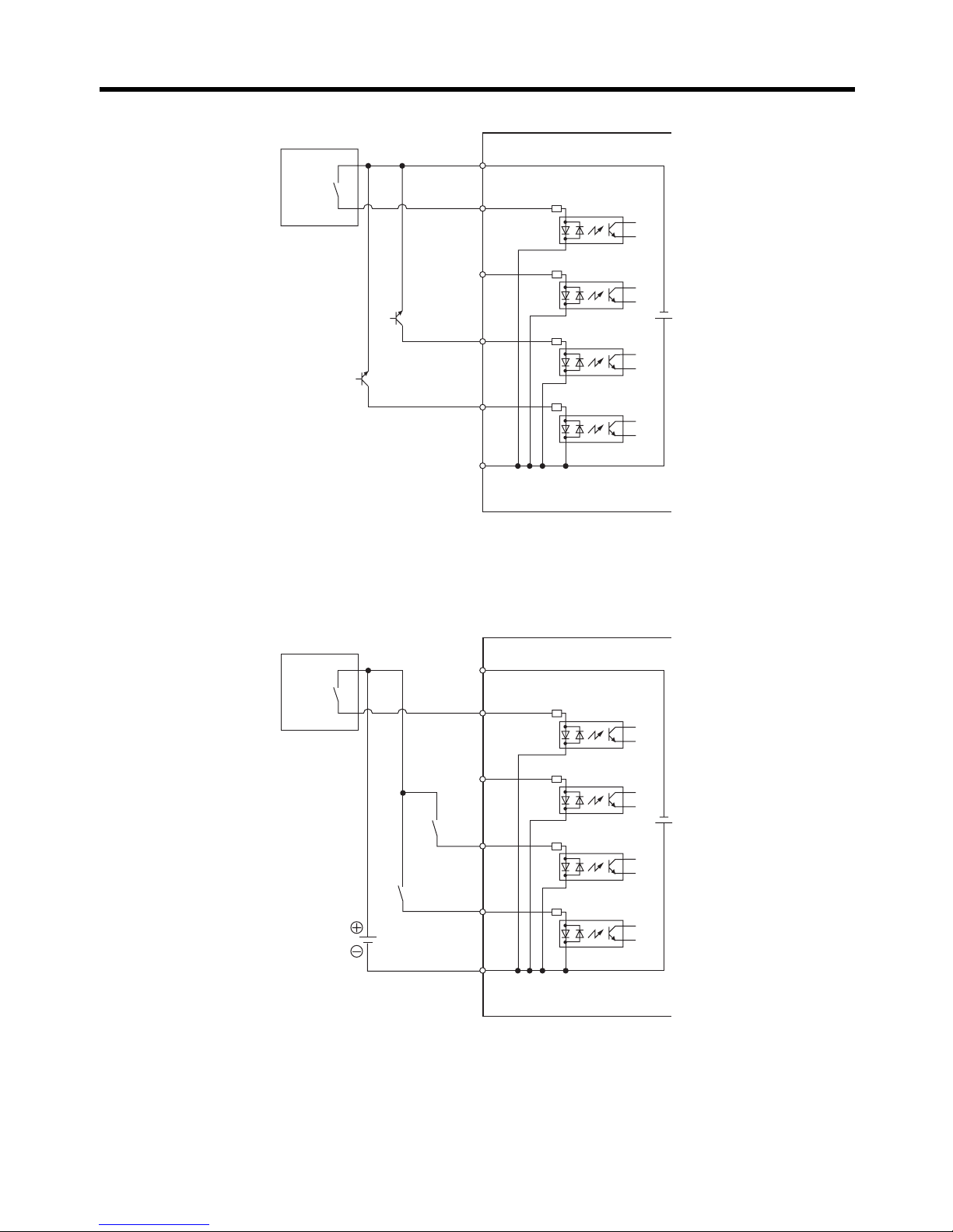
■ Control Circuit Input Terminal Connection Examples Using Internal 24-
V Power Supply for Models with PNP Input
● Connecting to Relay Circuits
● Connecting to PNP Transistors
Standard Models Communications Models
24 VDC
SS1
SS0
STF
STR
SC
1
3
4
5
6
2
RS-485 (+)
RS-485 (−)
24 VDC
STF
STR
SC
RS-485 (+)
RS-485 (−)
1
3
4
5
6
2
Standard Models Communications Models
1
3
4
5
6
2
SS0
SS1
STF
STR
SC
24 VDC
RS-485 (+)
RS-485 (−)
24 VDC
STF
STR
SC
RS-485 (+)
RS-485 (−)
1
3
4
5
6
2
Page 41

Chapter 2
2-19
Design
■ Control Circuit Input Terminal Connection Examples Using External 24-
V Power Supply for Models with PNP Input
● Connecting to Relay Circuits
● Connecting to PNP Transistors
24 VDC
24 VDC
RS-485 (+)
RS-485 (−)
Standard Models Communications Models
SS1
SS0
STF
STR
SC
1
3
4
5
6
2
STF
STR
SC
1
3
4
5
6
2
RS-485 (+)
RS-485 (−)
24 VDC
24 VDC
24 VDC
24 VDC
24 VDC
24 VDC
RS-485 (+)
RS-485 (−)
Standard Models Communications Models
SS1
SS0
STF
STR
SC
1
3
4
5
6
2
STF
STR
SC
1
3
4
5
6
2
RS-485 (+)
RS-485 (−)
Page 42

Chapter 2
2-20
Design
● Connecting to NPN Transistors
■ Control Circuit Input Terminal Connection Examples Using Internal 24-
V Power Supply for Models with NPN Input
● Connecting to Relay Circuits
24 VDC
24 VDC
24 VDC
24 VDC
RS-485 (+)
RS-485 (−)
Standard Models Communications Models
1
3
4
5
6
2
SS0
SS1
STF
STR
SC
STF
STR
SC
1
3
4
5
6
2
RS-485 (+)
RS-485 (−)
Standard Models Communications Models
SC
SS1
SS0
STF
STR
24
VDC
1
3
4
5
6
2
RS-485 (+)
RS-485 (−)
SC
STF
STR
24 VDC
RS-485 (+)
RS-485 (−)
1
3
4
5
6
2
Page 43

Chapter 2
2-21
Design
● Connecting to NPN Transistors
■ Control Circuit Input Terminal Connection Examples Using External 24-
V Power Supply for Models with NPN Input
● Connecting to Relay Circuits
Standard Models Communications Models
1
3
4
5
6
2
SS0
SS1
STF
STR
24
VDC
SC
RS-485 (+)
RS-485 (−)
SC
STF
STR
24 VDC
RS-485 (+)
RS-485 (−)
1
3
4
5
6
2
24 VDC
SC
RS-485 (+)
RS-485 (−)
Standard Models Communications Models
SS1
SS0
STF
STR
24
VDC
1
3
4
5
6
2
STF
STR
24 VDC
1
3
4
5
6
2
RS-485 (+)
RS-485 (−)
SC
24 VDC
Page 44

Chapter 2
2-22
Design
● Connecting to PNP Transistors
● Connecting to NPN Transistors
SC
24 VDC
24 VDC
SC
RS-485 (+)
RS-485 (−)
Standard Models Communications Models
SS1
SS0
STF
STR
24
VDC
1
3
4
5
6
2
STF
STR
24 VDC
1
3
4
5
6
2
RS-485 (+)
RS-485 (−)
SC
24 VDC
SC
24 VDC
RS-485 (+)
RS-485 (−)
Standard Models Communications Models
1
3
4
5
6
2
SS0
SS1
STF
STR
24
VDC
STF
STR
24 VDC
1
3
4
5
6
2
RS-485 (+)
RS-485 (−)
Page 45

Chapter 2
2-23
Design
■ Control Circuit Output Terminal Connection Examples
● Connecting Sinking Outputs
● Connecting Sourcing Outputs
(+)
(−)
Load
(+)
(−)
Load
Page 46

Chapter 2
2-24
Design
2-2-5 Connecting to a Digital Controller or Temperature
Controller
The 3G3JE provides an interface for connecting to the time-shared proportional pulse output of a
digital controller or temperature controller, so frequency references can be used when these devices
are used.
This section describes how to connect the Inverter to a digital controller.
Note The frequency references for time-shared proportional pulse output and frequency reference
selections cannot be used at the same time. If P11 (Frequency reference selection) is set to
T.C (Temperature controller time-shared proportional pulses), multi-step speed reference 0
(SS0) will be the temperature controller time-proportional pulse input and multi-step speed reference 1 (SS1) will be ignored.
■ Overview of Operation
The frequency setting is determined based on the ratio of ON time to OFF time within the frequency
reference upper and lower limit range.
• If the ON time is 0% and the OFF time is 100%, the frequency setting will be the frequency reference lower limit.
• If the ON time is 100% and the OFF time is 0%, the frequency setting will be the frequency reference upper limit.
For example, if time-shared proportional pulses are input when the frequency reference lower limit is
20 Hz, the upper limit is 60 Hz, the control period is 10 s, the ON time is 2 s, and the OFF time is 8 s,
then the frequency setting will be 28 Hz.
Frequency setting = Frequency reference lower limit + (Frequency reference upper limit
− Frequency
reference lower limit)
× (ON time/Control period)
= 20 Hz + (60 Hz
− 20 Hz) × (2 s/10 s)
= 20 Hz + 40 Hz
× 0.2
= 28 Hz
● Time Required to Switch Frequency Reference
The frequency of the time-proportional pulse input is calculated based on the ratio between the ON
time and OFF time. At least one time-shared proportional pulse control cycle of the digital controller
or temperature controller is required to switch the 3G3JE’s frequency reference.
■ Digital Controller and Temperature Controller Output Specifications
The digital controller or temperature controller that is connected must have the following output specifications.
• Relay output models
• Voltage output models (12 V
±10% output or 24 V ±10% output)
ON
OFF
2 s (ON time)
10 s (Control period of digital controller)
8 s (OFF time)
Page 47

Chapter 2
2-25
Design
Note When connecting to a digital controller or temperature controller with a voltage output, use a
3G3JE model with a PNP input. If a model with an NPN input is used, the power supply may be
short-circuited depending on the insulation method between the controller’s voltage output section and the power supply for other control input circuits.
■ Digital Controller and Temperature Controller Settings
• Set the control period as shown below for digital controllers and temperature controllers.
• If the control period is set shorter than the lower limit or longer than the upper limit, correct operation will not be possible.
■ 3G3JE Settings
• Set the frequency reference upper limit (P07) and frequency reference lower limit (P08).
• Operation will be at the frequency reference lower limit with the time-shared proportional pulse at
0%.
• Operation will be at the frequency reference upper limit with the time-shared proportional pulse at
100%.
Note If the frequency reference upper limit is greater than the maximum frequency, change the
setting of the maximum output frequency (P06).
• Set the frequency reference selection (P11) is set to time-shared proportional pulses (T.C).
Control period lower limit 3 s
Control period upper limit 10 s
Page 48

Chapter 2
2-26
Design
■ Connecting to a Digital Controller or a Temperature Controller with a
Relay Output for Models with PNP Input
Connect the controller to multi-step speed reference 0 (SS0) terminal. The multi-step speed reference 1 (SS1) terminal input will be disabled.
● Control Circuit Input Terminal Connection Examples Using Internal 24-V Power
Supply
Example 1
Example 2
Digital
Controller
1
3
4
5
6
2
SS0
SS1
STF
STR
SC
24 VDC
Digital
Controller
1
3
4
5
6
2
SS0
SS1
STF
STR
SC
24 VDC
Page 49

Chapter 2
2-27
Design
● Control Circuit Input Terminal Connection Examples Using External 24-V Power
Supply
Example 1
Example 2
Digital
Controller
24 VDC
1
3
4
5
6
2
SS0
SS1
STF
STR
SC
24 VDC
1
3
4
5
6
2
SS0
SS1
STF
STR
SC
Digital
Controller
24 VDC
24 VDC
Page 50

Chapter 2
2-28
Design
Example 3
■ Connecting to a Digital Controller or a Temperature Controller with a
Relay Output for Models with NPN Input
Connect the controller to multi-step speed reference 0 (SS0) terminal. The multi-step speed reference 1 (SS1) terminal input will be disabled.
● Control Circuit Input Terminal Connection Examples Using Internal 24-V Power
Supply
Example 1
Digital
Controller
24 VDC
1
3
4
5
6
2
SS0
SS1
STF
STR
SC
24 VDC
Digital
Controller
1
3
4
5
6
2
SS0
SS1
STF
STR
24
VDC
SC
Page 51
Chapter 2
2-29
Design
Example 2
● Control Circuit Input Terminal Connection Examples Using External 24-V Power
Supply
Example 1
Digital
Controller
1
3
4
5
6
2
SS0
SS1
STF
STR
24
VDC
SC
Digital
Controller
24 VDC
1
3
4
5
6
2
SS0
SS1
STF
STR
24
VDC
SC
Page 52

Chapter 2
2-30
Design
Example 2
Example 3
1
3
4
5
6
2
SS0
SS1
STF
STR
24
VDC
Digital
Controller
24 VDC
SC
Digital
Controller
SC
1
3
4
5
6
2
SS0
SS1
STF
STR
24
VDC
24 VDC
Page 53

Chapter 2
2-31
Design
■ Connecting to a Digital Controller or a Temperature Controller with a
Voltage Output for Models with PNP Input
Note When connecting to a digital controller or temperature controller with a voltage output, use a
3G3JE model with a PNP input. If a model with an NPN input is used, the power supply may be
short-circuited depending on the insulation method between the controller’s voltage output section and the power supply for other control input circuits.
• Connect the controller between the multi-step speed reference 0 (SS0) terminal and the external
power supply common terminal (SC).
• Connect the controller's positive (+) terminal to SS0, and the negative (
−) terminal to SC. The multi-
step speed reference 1 (SS1) terminal input will be disabled.
Page 54

Chapter 2
2-32
Design
● Control Circuit Input Terminal Connection Examples Using Internal 24-V Power
Supply
Example 1
Example 2
12/24 V OUT
GND
1
3
4
5
6
2
SS0
SS1
STF
STR
SC
24 VDC
Digital Controller
12/24 V OUT
GND
1
3
4
5
6
2
SS0
SS1
STF
STR
SC
24 VDC
Digital Controller
Page 55

Chapter 2
2-33
Design
● Control Circuit Input Terminal Connection Examples Using External 24-V Power
Supply
Example 1
Example 2
12/24 V OUT
GND
1
3
4
5
6
2
SS0
SS1
STF
STR
SC
24 VDC
Digital Controller
24 VDC
12/24 V OUT
GND
1
3
4
5
6
2
SS0
SS1
STF
STR
SC
24 VDC
Digital Controller
24 VDC
Page 56

Chapter 2
2-34
Design
2-2-6 Harmonics Suppression in General-purpose Inverters
(Input Current of 20 A Maximum)
When equipped with the AC Reactor specified in section 5-2-5, the 3G3JE meets the harmonic suppression guideline for general-purpose inverters (inverters with an input current of 20 A maximum)
issued by the Japan Electronic Device Industrial Council (JEDIC).
2-2-7 Guideline to Reduce Harmonics Emissions in Appliances
Receiving High Voltages or Special High Voltages
The 3G3JE meets the Guideline to Reduce Harmonics Emissions in Appliances Receiving High Voltages or Special High Voltages (JEITA).
■ Guideline Applicability
This guideline is applicable to the following appliances.
1. Appliances receiving power from a 6.6-kV network with a total capacity exceeding 50 kVA considering the harmonics emission rate for each type of installed device emitting harmonics (called the
equivalent capacity)
2. Appliances receiving power from a 22-kV or 33-kV network with equivalent capacity exceeding
300 kVA
3. Appliances receiving power from a 66-kV or higher network with equivalent capacity exceeding
2,000 kVA
The limit for harmonic current, calculation methods for the equivalent capacity, and calculation methods for the harmonic current for appliances receiving 6.6 kV are described below.
● Limit of Harmonic Current
The allowable value for the harmonic current flowing to the network from special appliances is calculated for each harmonic number by multiplying the harmonic current limit per kilowatt of contracted power given in the following table by the contracted power (in kilowatts).
Limits to Harmonic Current per kW of Contracted Power
(Unit: mA/kW)
Received
voltage (kV)
5th 7th 11th 13th 17th 19th 23rd Higher
than 23rd
6.6 3.5 2.5 1.6 1.3 1.0 0.90 0.76 0.70
Page 57

Chapter 2
2-35
Design
● Calculating the Equivalent Capacity per Inverter
The equivalent capacity for an inverter is calculated as follows:
Equivalent capacity = Inverter’s rated input capacity (Pi) x Coefficient
Here, the Inverter’s rated input capacity (Pi) is calculated based on the rated capacity of the applicable motor, as shown in the following table.
Inverter’s Rated Input Capacity
The coefficient is as shown in the following table for a three-phase general-purpose inverter.
■ Calculating the Harmonic Current per Inverter
Use the following formula: nth harmonic current [A] =
Fundamental frequency input current [A] x nth harmonic current ratio (%)/100
Here, the values in the following table are used for the fundamental frequency input current and
converted for a received voltage of 6.6 kV.
The following table is used to obtain the nth harmonic current ratio (%). Normally calculations are
performed only for the 5th and 7th harmonics.
Three-phase Bridge (Capacitor Smoothing)
(Unit: %)
Motor capacity
(kW)
Rated input capacity (Pi)
(kVA)
200 V 400 V
0.4 0.57
0.75 0.97
1.5 1.95
3 Three-phase
bridge (capacitor smoothing)
3-1 No reactor K
31
= 3.4 General-purpose inverters
Servo amplifiers
Elevators
Refrigeration and air condi-
tioning equipment
Other general-purpose
equipment
3-2 Reactor on AC side K
32
= 1.8
3-3 Reactor on DC side K
33
= 1.8
3-4 Reactors on AC and DC side K
34
= 1.4
Applicable motor [kW] 0.4 0.75 1.5
Fundamental frequency
input current [A]
200 V 1.61 2.74 5.50
400 V 0.81 1.37 2.75
Value converted for 6.6 kV [mA] 49 83 167
Harmonic number 5 7 11 13 17 19 23 25
No reactor 65 41 8.5 7.7 4.3 3.1 2.6 1.8
Reactor on AC side 38 14.5 7.4 3.4 3.2 1.9 1.7 1.3
Reactor on DC side 30 13 8.4 5.0 4.7 3.2 3.0 2.2
Reactors on AC and DC side 28 9.1 7.2 4.1 3.2 2.4 1.6 1.4
Page 58

Chapter 2
2-36
Design
As described below, the result is multiplied by the maximum equipment operating rate to reduce
the current.
The harmonic currents emitted by all devices at the rated operating status are totaled and then
multiplied by the maximum equipment operating rate to calculate the harmonic emission current.
The maximum equipment operating rate is the ratio of the total capacity of the devices emitting
harmonic current to the maximum capacity of the equipment when operating. The maximum capacity of the equipment when operating is the average value over a 30-minute period.
■ 3G3JE Harmonic Current Countermeasures
● AC Reactors
AC reactors are used to suppress harmonic current. Using an AC reactor will reduce the emission
rate of harmonic current as shown in the following table to improve the power rate on the Inverter’s
input side. The AC reactor functions to suppress sudden currents.
● Effect of AC Reactor
Harmonic
countermeasure
Harmonic current rate for harmonic numbers (%)
5th 7th 11th 13th 17th 19th 23rd 25th
None
(only Inverter)
65 41 8.5 7.7 4.3 3.1 2.6 1.8
AC Reactor 38 14.5 7.4 3.4 3.2 1.9 1.7 1.3
B1 B2
3G3JE
Inverter
AC Reactor
(optional)
R/L1
S/L2
T/L3
U/T1
V/T2
W/T3
Three-phase
200 to 230 VAC
M
3~
MCCB
Page 59

Chapter 2
2-37
Design
2-2-8 Conforming to EC Directives
■ Applicable Directives
• EMC Directive: EN 61800-3
• Low Voltage Directive: EN 61800-5-1
■ Concepts
● EMC Directive
OMRON products are designed for compliance with related EMC standards so that they can be more
easily built into other devices or the overall machine. The 3G3JE has been checked for conformity to
EN 61800-3 when the following installation and wiring methods are used. EMC-related performance
of the OMRON products that comply with EC Directives will vary depending on the configuration, wiring, installation, and other conditions of the equipment or control panel on which the OMRON products are installed. The customer must, therefore, perform the final check to confirm that devices and
the overall machine conform to EMC standards.
● Wiring the Power Supply
• Always connect the power input terminals (R/L1, S/L2, and T/L3) and power supply via a 3G3JVPRS2010J Noise Filter (rated current: 10 A).
• Reduce the length of the ground wire as much as possible.
• Locate the Noise Filter as close as possible to the Inverter.
● Connecting a Motor to the Inverter
• When connecting a motor to the Inverter, be sure to use a cable with a braided shield.
• Reduce the length of the cable as short as possible.
■ Conforming to the Low Voltage Directive
The 3G3JE conforms to EN 61800-5-1 when the following installation and wiring methods are used.
• The 3G3JE is an open-frame device. Always install it in a control panel.
• Always use reinforced or double insulated power supply/voltage (SELV) wiring for the control circuit
terminals.
• The Low Voltage Directive requires that protection from short-circuiting in the power supply wiring
be provided with a molded-case circuit breaker (MCCB). Always install an MCCB on the power supply side of the Inverter.
• Use one MCCB per Inverter.
• Use an MCCB with the rated current given in the following table.
Model number Rated current MCCB model examples
3G3JE-A2001 3 to 5 A ABS33Fb
ABS53Fb
ABS33b
ABS53b
3G3JE-A2002 3 to 5 A
3G3JE-A2004 5 A
Page 60

Chapter 2
2-38
Design
• Use crimp terminals with insulated sleeves for connection to the main circuit terminals.
• When not using a Braking Resistor or Braking Resistor Unit, connect crimp terminals with insulated
sleeves to the braking resistor connection terminals (B1 and B2).
Standard Wiring Diagram for Conformance to EC Directives
● Precaution on Models with NPN Input (3G3JE-A2@@@N)
NPN circuits cannot be used for safety circuits. Therefore, models with an NPN input cannot be
used for safety circuits specified in EN/IEC 60204-1.
L1 L1'
L2'
L3'
L2
L3
R/L1
S/L2
T/L3
U/T1
V/T2
W/T3
M
3~
1
2
3
4
5
7
8
9
10
6
Control circuit
terminal
Control circuit
terminal
SELV circuit SELV circuit
MCCB
EMC-compliant,
input-side noise filter
3G3JV-PRS2010J
3G3JE Inverter
Three-phase
200 to 230 V AC
Page 61

Chapter 3
Operation
3-1 Key Operation Flowchart
3-2 Procedure for Test Run
3-3 Performing a Test Run
3-4 RUN Mode
3-5 Adjustment Mode
3-6 Initial Settings Mode
Page 62

Chapter 3
3-2
Operation
■ Operation
• This Inverter can be set to operate from low speed to high speed. Operate the Inverter only after
sufficiently confirming the allowable range for the motor installation being used.
■ Operation after Power Interruptions
• If continuing operation is selected for the momentary power interruption restart selection (P09), the
system may unexpectedly start operation after a momentary power interruption is reset. Exercise
suitable caution.
■ Operation Command Selection
• If the operation command selection parameter (P10) is set to “PLC” to enable using the control circuit terminal inputs (STF and STR), the motor may start operation when the power supply is turned
ON or an alarm is reset if the control circuit terminals are left ON. Exercise suitable caution. Also, if
signals are checked during operation and a voltage is incorrectly applied to the control circuit terminals, the motor may start moving unexpectedly. Always check safety before performing signal
checks.
■ Motor Overheating Protection (Electronic Thermal)
• The Inverter uses an electronic thermal to protect the motor from overheating. Set the rated current
of the motor in the rated motor current parameter (P01). If more than one motor is operated with
one Inverter, set the rated motor current parameter (P01) to 0.0 to disable motor overload detection, and install a thermal relay between the Inverter and each motor. Set the thermal relay to 1.0
times the nameplate current at 50 Hz and to 1.1 times the nameplate current at 60 Hz.
Precautions for Safe Use
Precautions for Correct Use
Page 63

Chapter 3
3-3
Operation
3-1 Key Operation Flowchart
SP1
SP2
SP3
45 5
40.0
50.0
.
sp2
sp1
sp3
SP1: Frequency reference1
SP2: Frequency reference 2
SP3: Frequency reference 3
SP4: Frequency reference 4
ACC: Acceleration time
DEC: Deceleration time
LOD: Application selection
Frequency reference: Hz set
Output frequency: Hz out
Output current: A
P01: Rated motor current
P16: Communications
baud rate
P18: Communications
stop bits
P19: Communications parity
P20: Parameter initialization
Changed by Mode Key.
Changed by Mode Key.
Changed by Mode Key.
Changed by Mode Key.
Changed by Mode Key.
Display
Display
Display
Display/setting
Display/setting
Example: Changing the Set Value
Adjustment Mode
(1) Move to Adjustment Mode and
press the Enter Key to display
the present set value.
The data display will flash while
a set value is being changed.
(3) Press the Enter Key to enter
the desired setting.
Changed by Increment
and Decrement Keys.
Changed by Increment
and Decrement Keys.
Changed by Increment
and Decrement Keys.
Changed by Increment
and Decrement Keys.
Changed by Increment
and Decrement Keys.
Changed by Increment
and Decrement Keys.
Accumulated operating time:
Kh
Forward/reverse operation
selection: FWD/REV
P02: Accumulated operating
time standard
P03: DC injection braking
frequency
P04: Startup DC injection
braking time
P05: DC injection braking-
to-stop time
P06: Maximum output
frequency
P07: Frequency reference
upper limit
P08: Frequency reference
lower limit
P09:
Momentary power
interruption restart selection
P10: Operation command
selection
P11: Frequency reference
selection
P12: Multi-function output
selection
P14: Carrier frequency
selection
P15: Communications unit
number
P17: Communications
data length
P21: Accumulated operating
time clear
P15 through P19 are displayed and can be
set only for Communications Models.
Changed by
Increment and
Decrement Keys.
Changed by
Increment and
Decrement Keys.
Changed by
Increment and
Decrement Keys.
Changed by
Increment and
Decrement Keys.
Changed by
Increment and
Decrement Keys.
Changed by
Increment and
Decrement Keys.
Changed by
Increment and
Decrement Keys.
Changed by
Increment and
Decrement Keys.
Changed by
Increment and
Decrement Keys.
Changed by
Increment and
Decrement Keys.
Changed by
Increment and
Decrement Keys.
Changed by
Increment and
Decrement Keys.
Changed by
Increment and
Decrement Keys.
Changed by
Increment and
Decrement Keys.
Changed by
Increment and
Decrement Keys.
Changed by
Increment and
Decrement Keys.
Changed by
Increment and
Decrement Keys.
Changed by
Increment and
Decrement Keys.
Changed by
Increment and
Decrement Keys.
Changed by
Increment and
Decrement Keys.
Note: The data display will flash
while the setting is being
entered and will return to the
setting item name when the
flashing stops.
Mode can be change during
operation or when stopped.
Mode can be change
only when stopped.
Mode can be change only when stopped.
Mode cannot be change directly.
Adjustment Mode
RUN Mode
Power ON
Initial Settings Mode
All the indicators light when the power is turned ON.
(Key operations are disabled.)
(See
note 1.)
(See
note 2.)
Note 1:
2:
P11 can be set only on Standard Models.
P13: Reverse rotation prohibit
selection
(2) Use the Increment and
Decrement Keys to change
the set value.
Press the Mode Key for at least 1 s.
Press the Enter Key for at least 1 s.
Press the Mode Key for at least 1 s.
Page 64

Chapter 3
3-4
Operation
3-2 Procedure for Test Run
1. Installation and Mounting
Install the Inverter according to the installation conditions. Refer to page 2-4.
• Make sure that the installation conditions are met.
2. Wiring and Connection
Connect to the power supply and peripheral devices. Refer to page 2-6.
• Select peripheral devices that meet the specifications and wire correctly.
3. Power ON
Carry out the following pre-connection checks before turning ON the power supply.
Refer to page 3-5.
4. Checking the Display Status
Check to be sure that there are no faults in the Inverter. Refer to page 3-5.
5. Initializing Parameters
Initialize the parameters. Refer to page 3-5.
6. Setting Parameters
Set the parameters required for a test run. Refer to page 3-6.
7. No-load Operation
Start the motor without a load using the RUN Key. Refer to page 3-7.
8. Actual Load Operation
Connect the mechanical system and use the Digital Operator for operation. Refer to page 3-8.
9. Operation
Page 65

Chapter 3
3-5
Operation
3-3 Performing a Test Run
This section describes performing a test run. Refer to Chapter 2 Design for information on Inverter
installation and wiring.
■ Confirmation before Performing a Test Run
• Confirm that all installation conditions have been met.
• Confirm that peripheral devices that conform to all specifications have been used and that they are
wired correctly.
■ Checkpoints before Connecting the Power Supply
• Check that the power supply is of the correct voltage and that the power input terminals (R/L1, S/
L2, and T/L3) are connected correctly.
•3G3JE-A2@: Three-phase 200 to 230 V AC
• Make sure that the motor output terminals (U/T1, V/T2, and W/T3) are connected to the motor correctly.
• Make sure that the control circuit terminals and the control device are wired correctly. Make sure
that all control terminals are turned OFF.
• Set the motor to no-load status (i.e., not connected to the mechanical system).
■ Connecting the Power Supply
• After conducting the above checks, connect the power supply.
• The entire display and setting/monitoring indicators will light (except for the COM indicator) when
the power supply is turned ON. The display and indicators will read as follows if the Inverter is normal.
Data display: Shows the present frequency reference.
Simplified-LED indicators: Only frequency reference indicator (Hz set) will be lit.
• If an error has occurred, the error parameter will be displayed on the data display.
If that occurs, refer to Chapter 4 Maintenance Operations and take the required action.
■ Using Parameter Initialization (P20)
• Initialize the parameters using the following procedure before performing a trial run. When the
parameters are initialized, all values except for the accumulated operating time will be returned to
their default settings.
1 Turning ON the Power
2 Checking the Display Status
3 Initializing Parameters
Page 66

Chapter 3
3-6
Operation
• Parameter initialization is executed using P20 (parameter initialization) in the initial settings mode.
■ Setting the Rated Motor Current (P01)
• Set the motor current parameter in P01 before the trial run to prevent the motor from burning due to
overloading.
• Set the rated current indicated on the specifications nameplate of the motor that is to be used.
• This parameter is used for the electronic thermal function for detecting motor overload (E03). Setting it correctly protects the motor by preventing it from burning even if an overload occurs.
• Motor overload (E03) detection is disabled by setting the parameter to 0.0
• Refer to 3-6-1 Setting the Rated Motor Current for details on the rated motor current (P01).
Note The default setting for the rated motor current is the standard rated current of the maximum
applicable motor.
Key sequence Indicator Display example Description
None @ Hz set The entire display and simplified-LED indicators
will light (except for the COM indicator) when the
power supply is turned ON. The present frequency
reference will be displayed on the data display.
1s min.
None Press the Mode Key for at least 1 s to move to Ini-
tial Settings Mode.
None Set p20 using the Increment and Decrement Keys.
None Press the Enter Key. The set value will be entered.
None Press the Increment and Decrement Keys and
select ini. The data display will flash.
None Press the Enter Key. The set values will be initial-
ized to their default values except for the accumulated operating time. The data display will stop
flashing and p20 will be displayed.
1 s min.
@ Hz set Press the Mode Key for at least 1 s to return to the
RUN mode.
4 Setting Parameters
P01 Rated motor current Changes during
operation
No
Setting range 0.0 to 2.5 (A) Setting unit 0.1 A Default setting See note.
Maximum applicable
motor capacity
Default dated
current setting [A]
0.1 kW 0.6
0.2 kW 1.0
0.4 kW 2.0
10.0
p01
p20
abt
ini
p20
10.0
Page 67

Chapter 3
3-7
Operation
■ No-load Motor Operation
Before performing operation with the mechanical system actually connected, operate the motor with
no load (i.e., not connected to the mechanical system) using the Digital Operator keys.
• Check that no faults have occur in the Inverter during operation.
• Check that the directions of rotations match. If operation is in the wrong direction, reverse any two
of the motor output wires.
• The Increment and Decrement Keys can be used to change the frequency when the
@ Hz set indi-
cator is lit.
• Refer to 3-4-3 Changing the Frequency Reference for information on changing the frequency refer-
ence.
Key sequence Indicator Display example Explanation
1 s min.
None Press the Mode Key for at least 1 s to move to Ini-
tial Settings Mode.
None Use the Increment or Decrement Key to display
p01.
None Press the Enter Key to display the value currently
set in P01.
None Use the Increment or Decrement Key to set the
rated motor current for the motor that is to be used.
The display will flash while the value is being set.
None Press the Enter Key to enter the set value. The
data display will stop flashing and p01 will be displayed.
5 No-load Operation
Key sequence Indicator Display example Explanation
@ Hz set Go to RUN mode and press the Mode Key to light
the @
Hz set indicator. The present frequency
reference will be displayed on the data display.
@ Hz set Set the frequency using the Increment and Decre-
ment Keys.(It is recommended that the test run be
first conducted at low frequency.)
@ Hz set
@ RUN
Press the RUN Key.
The @ RUN Indicator will be lit.
@ Hz set
@ RUN
The frequency can be changed using the Increment and Decrement Keys.
p01
p01
2.0
1.8
p01
10.0
12.3
RUN
12.3
20.0
Page 68

Chapter 3
3-8
Operation
■ Stopping the Motor
• When finished operating the motor in the no-load state, press the STOP/RESET Key. The motor will
stop.
After checking the operation with the motor in no-load status, connect the mechanical system and
operate with an actual load using the Digital Panel keys.
• Confirm that the motor has stopped completely before connecting the mechanical system.
• Be sure to tighten all the screws when connecting the motor axis to the mechanical system.
• If an error occurs during operation, immediately press the STOP/RESET Key on the Digital Operator.
• First set the frequency reference to a low speed of one tenth the normal operating speed. (Set the
frequency reference somewhat lower than the actual operating speed.)
■ Checking the Operating Status
• Check that the operating direction is correct and that the machine is operating smoothly at slow
speed before increasing the frequency reference.
• After changing the frequency reference or the rotation direction, check that there is no vibration or
abnormal sound from the motor. Check the monitor display to confirm that the output current is not
becoming excessive.
• Refer to 3-4-4 Selecting Forward or Reverse Operation for information on forward/reverse operation
selection. If parameter initialization (P20) is performed, reverse operation will be prohibited (P13).
To change the direction of rotation for actual load operation, enable reverse operation (P13). Refer
to 3-6-9 Selecting Reverse Rotation Prohibition for information on the reverse rotation prohibit
selection (P13).
Key sequence Indicator Display example Explanation
@ RUN
Goes out.
Press the STOP/RESET Key to stop the motor.
The @ RUN indicator will go out and the motor
will stop.
6 Actual Load Operation
STOP
RESET
20.0
Page 69

Chapter 3
3-9
Operation
3-4 RUN Mode
3-4-1 Run/Stop Command
Set P01 in the initial settings mode to the rated current given on the motor’s nameplate before operation. Setting the rated current correctly will protect the motor from burning due to an overload. For
details on the procedure, refer to 3-6-1 Setting the Rated Motor Current.
■ Operating and Stopping
• Press the RUN KEY to operate the motor.
• Press the STOP/RESET KEY to stop the motor.
• The @ RUN indicator will light during operation.
• In RUN mode, operation can always be started or stopped regardless of whatever item is currently
being displayed.
Key sequence Indicator Display example Explanation
@ Hz set Go to RUN mode and press the Mode Key to
light the @
Hz set indicator. The present frequency reference will be displayed on the
data display.
@ RUN Press the RUN Key to start the motor. The @
RUN indicator will light.
@ RUN
Goes out.
Press the STOP/RESET Key to stop the motor.
The @
RUN indicator will go out.
60.0
RUN
60.0
STOP
RESET
60.0
Page 70

Chapter 3
3-10
Operation
3-4-2 Selecting the Item to be Displayed
■ Changing the Display Item
• The Mode Key can be pressed to change the display item in the order shown below.
• The display item can be change during operation or when operation is stopped.
Note The
@ RVS indicator will not light when forward operation is set and fwd will be displayed on the
data display
. If reverse operation is set, the @ RVS indicator will light and rev will be displayed
on the data display.
3-4-3 Changing the Frequency Reference
■ Range for Changing the Frequency Reference
• The frequency reference is set in increments of 0.1 Hz for less than 100 Hz and in increments of
1 Hz at 100 Hz or higher. The setting range for the frequency reference is between the frequency
reference upper limit (P07) and the frequency reference lower limit (P08) set in the initial settings
mode. (Set the frequency reference upper limit and frequency reference lower limit in initial settings
mode.)
■ Setting the Frequency Reference
• The frequency reference can be set during operation or while operation is stopped.
Display Key
sequence
Indicator Display
example
Explanation
Frequency reference
@ Hz set The entire display and simplified-LED indi-
cators will light (except for the COM indicator) when the power supply is turned ON.
The present frequency reference will be
displayed on the data display.
Output frequency
@ Hz out When the Mode Key is pressed while the @
Hz set indicator is lit, the output frequency
will be displayed. At the same time the @
Hz out indicator will light.
Output current @ A When the Mode Key is pressed while the @
Hz out indicator is lit, the present output
current will be displayed. At the same time
the @ A indicator will light.
Accumulated
operating time
@ Kh When the Mode Key is pressed while the @
A indicator is lit, the present accumulated
operating time will be displayed. At the
same time the @ Kh indicator light will light.
Forward/
reverse operation selection
None (See
note.)
(@ RVS)
When the Mode Key is pressed while the
@ Kh indicator is lit, the present direction of
rotation will be displayed. No indicator will
light.
60.0
0.0
0.0
0.0
fwd
Page 71

Chapter 3
3-11
Operation
3-4-4 Selecting Forward or Reverse Operation
• The rotation direction can be changed during operation or while operation is stopped.
• If parameter initialization (P20) is performed, reverse operation will be prohibited (P13). To change
the direction of rotation for actual load operation, enable reverse operation (P13). Refer to 3-6-9
Selecting Reverse Rotation Prohibition for information on the reverse rotation prohibit selection
(P13).
■ Selecting the Rotation Direction
Note The @ RVS indicator will not light when forward operation is set and fwd will be displayed on the
data display
. If reverse operation is set, the @ RVS indicator will light and rev will be displayed
on the data display.
Key sequence Indicator Display example Explanation
@ Hz set The entire display and simplified-LED indicators
will light (except for the COM indicator) when
the power supply is turned ON. The present frequency reference will be displayed on the data
display. (If @ Hz set does not light, press the
Mode Key to light it.)
@ Hz set Set the frequency reference using the Incre-
ment and Decrement Keys.
None @ Hz set The set value will be entered when the Incre-
ment and Decrement Keys are released and
acceleration or deceleration will start.
Key sequence Indicator Display example Explanation
None @ Hz set The entire display and simplified-LED indicators
will light (except for the COM indicator) when
the power supply is turned ON. The present frequency reference will be displayed on the data
display.
None Press the Mode Key. The forward/reverse oper-
ation setting will be displayed. (The present
rotation direction will be displayed on the data
display.)
None (See note.)
(@ RVS)
Set the direction of rotation using the Increment
and Decrement Keys. (Press the Increment Key
during forward operation to switch to reverse
operation. Press the Decrement Key during
reverse operation to switch to forward operation.)
60.0
10.0
10.0
6.0
fwd
reV
Page 72

Chapter 3
3-12
Operation
3-5 Adjustment Mode
• Switching from RUN mode to adjustment mode is possible at any time by pressing the Enter Key for
1 second or longer.
• Switching from adjustment mode back to RUN mode is possible by pressing the Enter Key for
1 second or longer when any of the following adjustment items is being displayed: SP1 to SP4,
ACC, DEC, or LOD. If a set value is being displayed, press the Enter Key to display the setting item
name.
3-5-1 Setting Frequency References 1 to 4
• Four frequency references can be remembered internally in the Inverter.
• The frequency references 1 to 4 are set in increments of 0.1 Hz for less than 100 Hz and in increments of 1 Hz for 100 Hz or greater.
• Frequency references 1 to 4 are enabled when P11 (frequency reference selection) is set to MSP
(multi-step speed reference).
■ Relation between Control Circuit Terminals and Frequency Reference
Multi-step speed reference 0 (SS0) and multi-step speed reference 1 (SS1) can be used together to
select one of the following frequency references.
Note Multi-step speed references are supported only for Standard Models.
SP1 Frequency reference 1 Changes during
operation
Ye s
Setting range 0.0 to 120 (Hz) Setting unit 0.1 Hz Default setting 10.0
SP2 Frequency reference 2 Changes during
operation
Ye s
Setting range 0.0 to 120 (Hz) Setting unit 0.1 Hz Default setting 0.0
SP3 Frequency reference 3 Changes during
operation
Ye s
Setting range 0.0 to 120 (Hz) Setting unit 0.1 Hz Default setting 0.0
SP4 Frequency reference 4 Changes during
operation
Ye s
Setting range 0.0 to 120 (Hz) Setting unit 0.1 Hz Default setting 0.0
Multi-step speed reference SS0 SS1
Frequency reference 1 (SP1) OFF OFF
Frequency reference 2 (SP2) ON OFF
Frequency reference 3 (SP3) OFF ON
Frequency reference 4 (SP4) ON ON
Page 73

Chapter 3
3-13
Operation
■ Setting Frequency References 1 to 4
3-5-2 Setting Acceleration and Deceleration Times
• The acceleration time and the deceleration time are set separately.
• The acceleration time is the time required to accelerate from 0% to 100% of the maximum output
frequency (P06), and the deceleration time is the time required to decelerate from 100% to 0% of
the maximum output frequency.
• The setting unit for the acceleration and deceleration times is 0.1 s for less than 100 s, and 1 s for
100 s or more.
• If the load inertia is high, the acceleration and deceleration times must be increased. For details,
refer to 7-1 Selecting the Inverter at the end of this manual.
• The acceleration/deceleration time between 0 and the frequency reference is calculated with the
following formula.
Acceleration/deceleration time = (Acceleration/deceleration time setting)
× (Frequency reference)
÷ (Maximum output frequency setting)
Note When accelerating from a stopped condition, the starting DC breaking time must be added.
Key sequence Indicator Display example Explanation
None @ Hz set The entire display and simplified-LED indicators
will light (except for the COM indicator) when
the power supply is turned ON. The present frequency reference will be displayed on the data
display.
1 s min.
None Pressing the Enter Key for 1 s or longer
changes the mode to the adjustment mode.
sp1 will be displayed on the data display.
None Select the item to be displayed using the Incre-
ment and Decrement Keys.
None When the Enter Key is pressed, the present set
value for the selected item will be displayed.
None Set the frequency reference using the Incre-
ment and Decrement Keys. The data display
will flash.
None When the Enter Key is pressed, the set value
will be entered. When the data display stops
flashing, operation will be returned to the set
item selection.
1 s min.
@ Hz set None Press the Enter Key for at least 1 s to return to
the RUN mode.
sp1 sp3
50
6.0
sp1
sp3
28.3
32.0
sp3
Page 74

Chapter 3
3-14
Operation
■ Setting the Acceleration Time
■ Setting the Deceleration Time
ACC Acceleration time Changes during
operation
No
Setting range 0.1 to 999 (s) Setting unit 0.1 s Default setting 10.0
DEC Deceleration time Changes during
operation
No
Setting range 0.1 to 999 (s) Setting unit 0.1 s Default setting 10.0
Key sequence Indicator Display example Explanation
None @ Hz set The entire display and simplified-LED indicators
will light (except for the COM indicator) when
the power supply is turned ON. The present frequency reference will be displayed on the data
display.
1 s min.
None Pressing the Enter Key for 1 s or longer
changes the mode to the adjustment mode.
sp1 will be displayed on the data display.
None Use the Increment and Decrement Keys to dis-
play acc on the data display.
None When the Enter Key is pressed, the present set
value will be displayed.
None Set the acceleration time using the Increment
and Decrement Keys. The data display will
flash.
None Pressing the Enter Key will enter the set value.
When the data displays stops flashing, the
adjustment item name will again appear on the
data display.
Key sequence Indicator Display example Explanation
None @ Hz set The entire display and simplified-LED indicators
will light (except for the COM indicator) when
the power supply is turned ON. The present frequency reference will be displayed on the data
display.
1 s min.
None Pressing the Enter Key for 1 s or longer
changes the mode to the adjustment mode.
sp1 will be displayed on the data display.
(Hz)
100%
0%
(t)
(Hz)
100%
0%
(t)
Acceleration time Deceleration time
Maximum output frequency (P06)
6.0
sp1
acc
10.0
20.5
acc
6.0
sp1
Page 75

Chapter 3
3-15
Operation
3-5-3 Selecting the Application (Setting V/f Patterns)
• Set the V/f pattern so that the motor output torque is adjusted to the required load torque.
• With the 3G3JE, either of the two patterns below can be selected as the pattern for V/f characteristics.
• The 3G3JE has an automatic torque boost function. The suitable torque characteristics can be
obtained by simply selecting the load application.
None Use the Increment and Decrement Keys to dis-
play dec on the data display.
None When the Enter Key is pressed, the present set
value will be displayed.
None Set the deceleration time using the Increment
and Decrement Keys. The data display will
flash.
None Pressing the Enter Key will enter the set value.
When the data displays stops flashing, the
adjustment item name will again appear on the
data display.
LOD Application selection Changes during
operation
No
Selected item CNV/FAN Default setting CNV
Selected item Characteristics and
application
Description
CNV (cnv) Constant torque character-
istics (for conveyers)
Select for applications such as conveyers, where the load
torque is uniform regardless of the rotation speed and the
load moment of inertia is high.
FAN (fan) Gradual decrease torque
characteristics (for fan)
Select for applications such as fans and pumps, where the
load torque is lower when the rotation speed is slower.
Key sequence Indicator Display example Explanation
dec
10.0
20.5
dec
0
Output voltage (V)
Frequency (Hz)
Constant torque
characteristics
Gradual decrease
torque characteristics
Page 76

Chapter 3
3-16
Operation
■ Setting the Application Selection
Key sequence Indicator Display example Explanation
None @ Hz set The entire display and simplified-LED indicators
will light (except for the COM indicator) when
the power supply is turned ON. The present frequency reference will be displayed on the data
display.
1 s min.
None Pressing the Enter Key for 1 s or longer
changes the mode to the adjustment mode.
sp1 will be displayed on the data display.
None Use the Increment and Decrement Keys to dis-
play lod on the data display.
None When the Enter Key is pressed, the present set
value will be displayed.
None Press the Increment and Decrement Keys to
select the application to match the usage. The
data display will flash.
None Pressing the Enter Key will enter the set value.
When the data displays stops flashing, the
adjustment item name will again appear on the
data display.
6.0
sp1
lod
fan
cnV
lod
Page 77

Chapter 3
3-17
Operation
3-6 Initial Settings Mode
• It is always possible to change from the RUN mode or adjustment mode to the initial settings mode
by pressing the Mode Key for at least one second while the motor is stopped.
• It is possible to change from the initial settings mode to the RUN mode by pressing the Mode Key
for at least one second while an initial settings mode parameter name (P01 to P21) is displayed.
Display the initial settings mode parameter name by pressing the Enter Key while the set value is
displayed.
• Any set values that are changed will become valid when the RUN mode is entered.
• If the power is turned OFF while a setting has being changed but before RUN mode is entered, the
change will be lost when power is turned back ON.
■ Example Settings in Initial Settings Mode
3-6-1 Setting the Rated Motor Current
• Set P01 to the rated current given on the motor’s nameplate before operation. Setting the rated current correctly will protect the motor from burning due to an overload. Read the information in Motor
Overheating Protection (Electronic Thermal) under Precautions for Correct Use on page 3-2.
Key sequence Indicator Display example Explanation
None @ Hz set The entire display and simplified-LED indicators
will light (except for the COM indicator) when
the power supply is turned ON. The present frequency reference will be displayed on the data
display.
1 s min.
None Pressing the Mode Key for 1 s or longer
changes the mode to the initial settings mode.
p01 will be displayed on the data display.
None Select the item to be displayed using the Incre-
ment and Decrement Keys.
None When the Enter Key is pressed, the present set
value for the selected item will be displayed.
None Use the Increment and Decrement Keys to
make the setting. The data display will flash.
None Pressing the Enter Key will enter the set value.
When the data displays stops flashing, the
adjustment item name will again appear on the
data display.
1 s min.
@ Hz set Press the Mode Key for at least 1 s to return to
the RUN mode.
p01 p06
60.0
6.0
p01
p06
60.0
58.3
p06
6.0
Page 78

Chapter 3
3-18
Operation
• Motor overload (E03) detection is disabled by setting the parameter to 0.0.
Note The default setting for this parameter is the common rated current of the maximum applicable
motor.
3-6-2 DC Injection Braking Function
The DC injection braking function applies a DC voltage to the induction motor for braking control.
• Startup DC Injection Braking Time
This braking is used for stopping and starting a motor rotating by inertia with no regenerative processing.
• DC Injection Braking-to-stop Time
Adjust the stop DC injection braking time if the motor rotating does not decelerate to a stop in normal operation due to inertia. Increasing the DC injection braking time or DC injection braking frequency reduces the time required to stop the motor.
• When starting, acceleration will start after the startup DC injection braking time (P04) has elapsed.
• After decelerating to the DC injection braking frequency (P03) when stopping, DC injection braking
will be applied for the DC injection braking-to-stop time (P05).
P01 Rated motor current Changes during
operation
No
Setting range 0.0 to 2.5 (A) Setting unit 0.1 A Default setting See note.
Maximum applicable
motor capacity
Default dated
current setting [A]
0.1 kW 0.6
0.2 kW 1.0
0.4 kW 2.0
P03 DC injection braking frequency Changes during
operation
No
Setting range 0.0 to 5.0 (Hz) Setting unit 0.1 Hz Default setting 3.0
P04 Startup DC injection braking time Changes during
operation
No
Setting range 0.0 to 10.0 (s) Setting unit 0.1 s Default setting 0.0
P05 DC injection braking-to-stop time Changes during
operation
No
Setting range 0.0 to 10.0 (s) Setting unit 0.1 s Default setting 0.5
Page 79

Chapter 3
3-19
Operation
DC Braking Operation
3-6-3 Maximum Output Frequency
• This parameter functions as a frequency limiter.
• Acceleration and deceleration times are defined as the times required to reach the maximum output
frequency (P06) from 0 Hz and to reach 0 Hz from the maximum output frequency (P06).
Note The setting unit for the frequency reference upper and lower limits is 0.1 Hz for less than
100 Hz, and 1 Hz for 100 Hz or higher.
3-6-4 Setting Frequency Reference Upper and Lower Limits
• Upper and lower limits are set for the frequency reference input from the Digital Operation, frequency references 1 to 4, time-proportional pulse inputs, or communications.
• If the frequency reference lower limit (P08) is higher than the frequency reference upper limit (P07),
operation will be at the frequency lower limit.
• If the frequency reference upper limit (P07) or frequency reference lower limit (P08) is set higher
than the maximum output frequency (P06), the maximum output frequency will be used for the frequency reference upper limit or frequency reference lower limit. (The settings will be automatically
replaced when RUN mode is entered.)
Note The setting unit for the frequency reference upper and lower limits is 0.1 Hz for less than 100
Hz, and 1 Hz for 100 Hz or greater.
P06 Maximum output frequency Changes during
operation
No
Setting range 50.0 to 120 (Hz) Setting unit 0.1 Hz (See note.) Default setting 60.0
P07 Frequency reference upper limit Changes during
operation
No
Setting range 0.1 to 120 (Hz) Setting unit 0.1 Hz (See note.) Default setting 60.0
Time
(P05)
(P04)
Output frequency
Startup DC injection braking time
DC injection
braking frequency
(P03)
DC injection braking-tostop time
Page 80

Chapter 3
3-20
Operation
3-6-5 Selecting the Processing after Recovery from a
Momentary Interruption
• Use this parameter to select the processing to be performed when a momentary power interruption
occurs.
• When setting 1 or 2 is selected, an alarm is output when low voltage is detected in the main circuit,
and the alarm is automatically cancelled when the normal voltage resumes.
• If the power interruption is longer that the time for which Inverter operation can be performed, the
operation after recovery from the power interruption will be the same as the startup operation.
3-6-6 Selecting Operation Commands
• This parameter selects the input method for specifying Inverter starting, stopping, and direction of
rotation.
• There are two methods that can be selected for operation commands. Select the best method for
the application.
P08 Frequency reference lower limit Changes during
operation
No
Setting range 0.1 to 120 (Hz) Setting unit 0.1 Hz (See note.) Default setting 0.0
P09 Momentary power interruption restart selection Changes during
operation
No
Setting range 0 to 2 Default setting 0
Set value Description
0 (0) Inverter stops operating. (If the interruption lasts for 15 ms or longer, main circuit low voltage
will be detected and an error will occur.)
1 (1) Inverter continues operating if power interruption is 0.5 s or less. (If a power interruption
occurs when 1 is set for 0.5 s, the main circuit low voltage is detected and outputs are
stopped while waiting for power to be restored. If power is restored within 0.5 s, operation
resumes.)
2 (2) Inverter always continues operating. (If a power interruption occurs when 2 is set, outputs are
stopped while waiting for power to be restored. When power is restored, outputs are
resumed.)
P10 Operation command selection Changes during
operation
No
Selected item Key/PLC Default setting Key
Selected item Description
Key (key) Operation commands are performed using the Digital Operator keys.
PLC (plc) Operation commands are performed using the STF and STR control inputs.
Page 81

Chapter 3
3-21
Operation
3-6-7 Frequency Reference Selection
• This parameter selects the method for inputting frequency references for the Inverter.
• There are three methods for inputting frequency references. Select the method according to the
application.
Note 3G3JE Communications Models (RS-485) do not have external inputs to select the frequency,
so this parameter is not displayed.
Description of Selections
3-6-8 Selecting the Function for the Multi-function Output
This parameter is used to select the function of the multi-function output.
Description of Set Values
P11 Frequency reference selection Changes during
operation
No
Selected item Key/MSP/T.C Default setting Key
Selected item Description
Key (key) Frequency reference set using Digital Operator keys.
MSP (msp) Frequency reference according to multi-step speed reference 0 (SS0) and multi-step speed
reference 1 (SS1).
T.C ( t.c) Frequency reference using temperature controller time-shared proportional pulses via multi-
step speed reference 0 (SS0).
P12 Multi-function output selection Changes during
operation
No
Setting range 0 to 3 Default setting 0
Set value Function name Description
0 (0) Not allocated --1 (1) Zero speed Output turned ON when the output frequency is 0 Hz or opera-
tion is stopped.
2 (2) Frequency matching Output turned ON when the output frequency and the frequency
reference are the same.
3 (3) Reverse operation Output turned ON when the direction of rotation is set for
reverse operation.
Page 82

Chapter 3
3-22
Operation
3-6-9 Selecting Reverse Rotation Prohibition
• This parameter is used to specify whether to enable or disable a reverse rotation command sent to
the Inverter.
• The parameter must be set to prohibit reverse operation when the Inverter is applied to applications
in which reverse rotation of the Inverter would cause problems.
3-6-10 Setting the Carrier Frequency
• With the 3G3JE, it is possible to switch between two carrier frequencies.
• Change the carrier frequency in the following cases.
Reduce the carrier frequency to 4 kHz if there are fluctuations in the speed or torque at low speeds
or if the wiring distance between the Inverter and motor is excessively long.
3-6-11 Initializing Parameters
• The parameters can be initialized to their default values.
• Parameters are initialize when P20 is set to “ini” and then the Enter Key is pressed.
• The frequency reference will also be initialized to the default value.
• The motor accumulated operating time will not be initialized.
P13 Reverse rotation prohibit selection Changes during
operation
No
Selected item F. R / F W D Default setting FWD
Selected item Description
F. R ( f.r) Allow reverse operation
FWD (fwd) Prohibit reverse operation (reverse operation disabled)
Wiring distance Carrier frequency (guideline)
50 m or less 4 kHz or 7 kHz
Longer than 50 m 4 kHz
P14 Carrier frequency selection Changes during
operation
No
Setting range 4/7 (kHz) Default setting 4k
Set value Description
4 (4k)4 kHz
7 (7k)7 kHz
P20 Parameter initialization Changes during
operation
No
Setting range ini/abt Default setting abt
Set value Description
ini (ini) Initialize
abt (abt) Abort
Page 83

Chapter 3
3-23
Operation
3-6-12 Motor Accumulated Operating Time
• The 3G3JE keeps track of the motor's accumulated operating time. An alarm is output when the
motor's total operating time reaches the accumulated operating time standard. This function can be
useful in managing the equipment's maintenance periods.
● Accumulated Operating Time Standard
This parameter sets the accumulated operating time standard for outputting the accumulated operating time alarm (E09).
Note 1 Kh=1000 hours
● Accumulated Operating Time Clear
• This parameter is used to reset the accumulated operating time to zero when equipment maintenance is performed or when the motor is replaced. The time is cleared when the parameter is set to
“ini”.
• To clear the accumulated operating time alarm, either or both of the following two methods must be
used.
1.Increase the accumulated operating time standard to a value greater than the present set value.
This method does not reset the accumulated operating time, so the alarm will be output again
when the motor's operating time reaches the new accumulated operating time standard.
2.Reset the accumulated operating time.
The alarm will again be output at the point where the motor's operating time reaches the accumulated operating time standard from the point where it was cleared.
3-6-13 Setting Communications
■ Communications Settings
This section describes how to set the parameters (P15 to P19) for Communications Models (RS-
485). There are five parameters that can be set: Communications unit number, baud rate, data
length, stop bits, and parity.
Note For details on communications specifications, wiring, and communications commands, refer to
the Communications Manual.
P02 Accumulated operating time standard Changes during
operation
No
Setting range 0.0 to 99.9 Setting unit 0.1 Kh Default setting 20.0
P21 Accumulated operating time clear Changes during
operation
No
Setting range ini/abt Default setting abt
Set value Description
ini (ini) Resets the accumulated operating time to 0.0.
abt (abt)Abort
Page 84

Chapter 3
3-24
Operation
● Setting the Communications Unit Number
Sets the Communications unit number.
● Setting the Communications Baud Rate
Sets the communications baud rate.
● Setting the Communications Data Length
Sets the communications data length.
● Setting the Communications Stop Bits
Sets the number of communications stop bits.
P15 Communications unit number Changes during
operation
No
Setting range 0 to 99 Default setting 1
P16 Communications baud rate Changes during
operation
No
Setting range 2.4/4.8/9.6/19.2 (kbps) Default setting 9.6
Selected item Description
24 (24) 2.4 kbps
48 (48) 4.8 kbps
96 (96) 9.6 kbps
192 (192) 19.2 kbps
P17 Communications data length Changes during
operation
No
Setting range 7/8 (bits) Default setting 7
Selected item Description
7 (7) 7 bits
8 (8) 8 bits
P18 Communications stop bits Changes during
operation
No
Setting range 1/2 (bits) Default setting 2
Selected item Description
1 (1)1 bit
2 (2) 2 bits
Page 85

Chapter 3
3-25
Operation
● Setting the Communications Parity
Sets the communications parity.
P19 Communications parity Changes during
operation
No
Selected item None/even/odd Default setting Even
Selected item Description
non (non)None
evn (evn)Even
odd (odd)Odd
Page 86

Chapter 3
3-26
Operation
Page 87

Chapter 4
Maintenance Operations
4-1 Protective and Diagnostic Functions
4-2 Troubleshooting
4-3 Maintenance and Inspection
Page 88

Chapter 4
4-2
Maintenance Operations
■ Operation and Maintenance
• Take measures to assure safety before performing maintenance or inspection, or replacing components.
■ Operation Command Selection
• If the operation command selection parameter (P10) is set to “PLC” to enable using the control circuit terminal inputs (STF and STR), the motor may start operation when the power supply is turned
ON or an alarm is reset if the control circuit terminals are left ON. Exercise suitable caution. Also, if
signals are checked during operation and a voltage is incorrectly applied to the control circuit terminals, the motor may start moving unexpectedly. Always check safety before performing signal
checks.
■ Disposing of the Inverter
• Observe all applicable legal requirements when disposing of the Inverter.
Caution
Do not touch the Inverter terminals while the power is being supplied or for at least
one minute after the power has been turned OFF.
Doing so may occasionally result in minor injury from electrical shock.
Do not remove the fan cover except when replacing the fan. Before replacing the fan,
first turn OFF the power and disconnect the wiring.
Doing so may occasionally result in minor injury from electrical shock.
Precautions for Safe Use
Precautions for Correct Use
Page 89

Chapter 4
4-3
Maintenance Operations
4-1 Protective and Diagnostic Functions
This section describes the fault information output for Inverter protection, motor burning protection,
and Inverter internal circuit protection. If a fault occurs, refer to Fault Displays and Corrective Mea-
sures on page 4-4 and take suitable corrective measures.
■ Inverter Faults
• If a fault occurs, the Inverter will display a fault message on the Digital Operator.
• The fault contact output will operate and the Inverter output will be turned OFF, causing the motor to
coast to a stop.
Note The stopping method can be selected for some faults.
• Inverter output will not be interrupted for an accumulated operating time fault.
■ Clearing Faults
Faults can be cleared using any of the following methods.
• Turn the power supply OFF and back ON again.
• If the PLC has been selected for the operation command selection (P10), turn STF ON and then
OFF again.
• If key operations have been selected for the operation command selection (P10), press the STOP/
RESET Key on the Digital Operator.
• Execute the STOP/RESET operation command with a communications command. (This can be
done with Communications Models only.)
Page 90

Chapter 4
4-4
Maintenance Operations
■ Fault Displays and Corrective Measures
Fault
display
Fault name and
meaning
Probable cause Correction
e02 Overcurrent
The momentary overcurrent (250% of rated
output current) was
exceeded.
The overload rated
current (150% of rated
output current for
1 min) was detected.
A short-circuit or ground fault has
occurred at the Inverter output.
Check and correct the motor
power cable.
A fault has occurred in the machine. Correct the machine fault.
The motor capacity is too large for the
Inverter.
Reduce the motor capacity to
the maximum permissible
motor capacity or less.
The Inverter capacity is insufficient. Increase the Inverter capacity.
The magnetic contactor on the output
side of the Inverter has been opened
and closed.
Rearrange the sequence so
that the magnetic contactor
will not open or close while the
Inverter is outputting a
current.
The acceleration/deceleration time is
too short.
Increase the acceleration/
deceleration time.
The output circuit of the Inverter is
damaged.
Replace the Inverter.
The load is too large. Reduce the load.
e03 Motor overload
The electronic thermal
relay actuated the
motor overload protective function.
The load is too large. • Reduce the load.
• Increase the motor capacity.
The acceleration/deceleration time is
too short.
Increase the acceleration/
deceleration time.
The value in P01 for rated motor cur-
rent is incorrect.
Check the motor nameplate
and set P01 to the rated cur-
rent.
The Inverter is driving more than one
motor.
Disable the motor overload
detection function and install a
thermal relay for each of the
motors. The motor overload
detection function is disabled
by setting P01 to 0.0.
e04 Overvoltage
The main circuit DC
voltage reached the
overvoltage detection
level (410 V DC min.)
during Inverter operation.
The deceleration time is too short. Increase the deceleration
time.
The power supply voltage is too high. Decrease the voltage to within
specifications.
There is excessive regenerative energy
due to overshooting at the time of
acceleration.
Suppress the overshooting as
much as possible.
Page 91

Chapter 4
4-5
Maintenance Operations
e05 Main circuit under-
voltage
The main circuit DC
voltage reached the
undervoltage detection level (200 V DC)
during Inverter operation.
Power supply to the Inverter has phase
loss or the power cable is disconnected.
Check the wiring and check
for loose screws and disconnected wires and correct any
problems.
Incorrect power supply voltage Make sure that the power sup-
ply voltage is within specifications
Momentary power interruption has
occurred.
• Use the momentary power
interruption restart (Set P09
to 1 or 2.)
• Improve the power supply
The internal circuitry of the Inverter is
damaged.
Replace the Inverter.
e06 Radiation fin over-
heated
The temperature of the
radiation fins of the
Inverter has exceeded
the specified temperature.
The ambient temperature is too high. Ventilate the Inverter or install
a cooling unit.
The installation space is insufficient. Increase the space around the
Inverter.
The load is too large. • Reduce the load.
• Increase the Inverter capacity.
The acceleration/deceleration time is
too short.
Increase the acceleration/
deceleration time.
The ventilation is obstructed. Change the location of the
Inverter to meet the installation conditions.
The cooling fan of the Inverter does not
work. (The cooling fan's service life has
expired, or the fan is broken.)
Replace the cooling fan.
(Applies to Inverters with
fans.)
e07 Cooling fan fault
The cooling fan has
been locked (stopped)
or the rotation speed is
down by 30% or more.
Note: The motor output
will stop if it’s locked or
the speed is down by
50% or more. A fault
will be output if the
speed is down 30% or
more.
The cooling fan wiring has a fault. Turn OFF the Inverter, remove
the Inverter, and check and
repair the wiring.
The cooling fan is not in good condition. Check and remove the for-
eign material or dust on the
fan.
The cooling fan is faulty or beyond its
service life.
Replace the fan.
e08 Braking IGBT fault
The brake IGBT is malfunctioning.
The IGBT is damaged. Turn OFF the Inverter power
immediately, and replace the
Inverter.
e09 Accumulated time
alarm
The Inverter's accumulated time has
reached the accumulated operating
time standard (P02) that was set.
To cancel the alarm, set the
accumulated operating time
clear parameter (P21) to ini, or
increase the existing accumulated operating time standard
(P02).
Fault
display
Fault name and
meaning
Probable cause Correction
Page 92

Chapter 4
4-6
Maintenance Operations
e01 Memory fault
A fault was detected in
the Inverter's internal
memory.
Internal circuit fault If the fault persists even after
the power has been turned
OFF and back ON, then
replace the Inverter.
t5t EEPROM write error A power interruption occurred during
an overload.
Turn the Inverter power OFF
and back ON. (The immediately preceding accumulated
operating time is not added.)
Not lit Power supply fault,
power supply undervoltage, control
power supply fault,
or hardware error
No power supply is provided. Check and correct the power
supply wire and voltage.
Terminal screws are loosened. Check and tighten the termi-
nal screws.
The Inverter is damaged. Replace the Inverter.
Fault
display
Fault name and
meaning
Probable cause Correction
Page 93

Chapter 4
4-7
Maintenance Operations
4-2 Troubleshooting
Due to parameter setting errors, faulty wiring, and so on, the Inverter and motor may not operate correctly. If that should occur, use this section as a reference and take the appropriate measures.
Refer to 4-1 Protective and Diagnostic Functions, if a fault is displayed.
Parameters cannot be set.
The motor does not operate.
• The stall prevention function has operated during acceleration. The acceleration time is automatically increased to make tripping less likely to occur due to overcurrent during acceleration.
• The stall prevention function has operated during deceleration. The deceleration time is automatically increased to make tripping less likely to occur due to overvoltages during deceleration.
Problem Probable cause Correction
The display does not
change when a key is
pressed.
Initial settings mode cannot be
entered during operation.
Turn OFF the Inverter and then make the settings.
Nothing is displayed on
the Digital Operator.
Cannot be determined. If the fault persists even after the power has
been turned OFF and back ON, then replace
the Inverter.There is an internal circuit fault.
Problem Probable cause Correction
The motor does not
operate with input
through the control circuit terminals
PLC is not selected in the operation command selection (P10).
If “Key” (Digital Operator keys) is selected for
the operation command selection (P10), operations cannot be specified from the control circuit terminals. Select PLC in the operation
command selection (P10).
The wiring of the control circuit
terminals of the Inverter is incorrect.
The Inverter cannot check the input signal if
the input line of the control circuit terminals is
incorrectly wired. Refer to 2-2-4 Wiring Control
Circuit Terminals and check that the terminals
are wired according to the correct wiring
method.
The motor stops during
acceleration/deceleration or when a load is
connected.
The load may be too big. The 3G3JE has a stall prevention function and
automatic torque boost function, but the motor
responsiveness limit may be exceeded if
acceleration is too rapid or if the load is too
big. Lengthen the acceleration time or reduce
the load. Also consider increasing the motor
capacity.
The motor operates at a
frequency lower than
the frequency reference.
The load may be too big. The overcurrent protection may operate when
the output current exceeds 150% of the
Inverter’s rated current, lowering the output frequency. Reduce the load.
Page 94

Chapter 4
4-8
Maintenance Operations
■ The Inverter does not operate or the motor operates only briefly when
the Controller power supply is turned OFF.
● Faulty Sequence
The motor will not operate if both the Forward/Stop Command (STF) and the Reverse/Stop Command (STR) are input at the same time. Correct the sequence.
● Malfunction due to Unwanted Current Path (when Using an Internal Power Supply
for a Model with an NPN Input)
The Inverter input may remain ON if there is an unwanted current path in the controller output.
With the wiring shown below, the Inverter input will operate due to the current path indicated by the
arrow if the controller output power supply is less than 24 VDC or the power supply is OFF. If this
occurs, insert a diode as indicated in the diagram at section A.
Controller (Output Unit)
Inverter (Control input)
SS0
SS1
STF
STR
SC
GND
Section A
24 V
Page 95

Chapter 4
4-9
Maintenance Operations
The motor only rotates in one direction.
The motor is rotating in the wrong direction.
The motor is burning out.
Problem Probable cause Correction
Reverse rotation prohibition is selected.
If P13 (reverse rotation prohibit
selection) is set to FWD (prohibit
reverse operation), the Inverter
will not accept reverse-rotation
commands.
To use both forward and reverse rotation, set
P13 to “F.R.”
Problem Probable cause Correction
The output wiring of the
motor is faulty.
The U/T1, V/T2, and W/T3 terminals of the Inverter are not properly connected to the U, V and W
terminals of the motor.
When the U/T1, V/T2, and W/T3 terminals of
the Inverter are properly connected to the U, V
and W terminals of the motor, the motor will
operate in a forward direction when a forward
rotation command is executed. The forward
direction depends on the manufacturer and the
motor type. Therefore, be sure to check the
specifications.Switching two wires among the
U/T1, V/T2, and W/T3 will reverse the direction
of rotation.
Problem Probable cause Correction
The load is too big. If the load of the motor is too big
and the motor is used with the
effective torque exceeding the
rated torque of the motor, the
motor will burn out.
Reduce the load amount by either reducing the
load or lengthening the acceleration/deceleration time. Also consider increasing the motor
capacity.
Note: For example, the rated torque of the
motor and capacity may be limited to eight
hours of use if the inscription on the motor
states that the motor is rated for eight hours. If
the 8-hour rated torque is used for normal
operation, it may cause the motor to burn out.
The ambient temperature is too high
The rating of the motor is determined within a particular ambient
operating temperature range. The
motor will burn out if it runs continuously at the rated torque in an
environment in which the maximum ambient operating temperature is exceeded.
Lower the ambient temperature of the motor to
within the acceptable ambient operating temperature range.
The withstand voltage
between the phases of
the motor is insufficient.
When the motor is connected to
the output of the Inverter, a surge
will be generated between the
switching of the Inverter and the
coil of the motor. Normally, the
maximum surge voltage is
approximately three times the
input power supply voltage of the
Inverter (i.e., approximately 600 V
for 200-V Inverters).
Therefore, the dielectric strength of the motor
to be used must be higher than the maximum
surge voltage.
Page 96

Chapter 4
4-10
Maintenance Operations
Controller or AM radio receives noise when Inverter is started.
The ground fault interrupter is actuated when Inverter is started.
There is mechanical vibration.
Problem Probable cause Correction
Noise derives from
Inverter switching.
Take the measures to prevent
noise. Noise can be reduced to
some extent.
Lower the carrier frequency of the Inverter in
P14 to 4 kHz.
Install an Input Noise Filter on the power input
area of the Inverter.
Install an Output Noise Filter on the output
area of the Inverter.
Enclose the Inverter with a metal shield and
ground the shield.
Problem Probable cause Correction
Leakage current flows
through the Inverter.
The Inverter performs internal
switching. Therefore, a leakage
current flows through the Inverter.
This leakage current may actuate
the ground fault interrupter, shutting the power OFF.
Note: In addition, remember that a
leakage current increases in proportion to the cable length. (Normally, approximately 5 mA of
leakage current is generated for
each meter of cable.)
Use a ground fault interrupter with a high leakage-current detection value (sensitivity amperage of 200 mA or more, operating time of 0.1 s
or more) or one with high-frequency countermeasures for Inverter use. Reducing the carrier frequency value in P14 is also effective.
Problem Probable cause Correction
The mechanical system is making unusual
noise.
Resonance is occurring between
the characteristic frequency of the
mechanical system and the carrier frequency.
If the motor is running with no problems and
the machinery system is vibrating with a highpitched whine, it may indicate that there resonance is occurring between the characteristic
frequency of the mechanical system and the
carrier frequency. To prevent this type of resonance, adjust the carrier frequency value in
P14.
Resonance is occurring between
the characteristic frequency of the
mechanical system and the output frequency of the Inverter.
Install vibration-proof rubber on the motor
base to prevent the resonance of the mechanical system.
The motor vibrates
excessively and does
not rotate normally.
Motor Phase Interruption.
If one or two of the three phases
of the motor are open, the motor
will vibrate excessively and will
not rotate.
Check that the motor is wired correctly without
any disconnection. The same phenomenon
will occur if the output transistor of the Inverter
is open and damaged. Check the balance of
the Inverter's output voltage as well.
Page 97

Chapter 4
4-11
Maintenance Operations
The motor rotates even after Inverter output is stopped.
When the motor starts, an overcurrent fault (E02) is detected and the motor stalls.
Problem Probable cause Correction
The motor rotates even
after Inverter output is
stopped.
If the motor continues operating at
low speed, without completely
stopping, even after a deceleration stop has been executed, it
means that the DC injection braking is not decelerating enough.
Increase the parameter in P05 for DC injection
braking-to-stop time or increase the deceleration time.
Problem Probable cause Correction
When the motor starts,
an overcurrent fault
(E02) is detected and
the motor stalls.
DC injection braking is insufficient
at startup. This can also occur if
the motor is already turning when
the motor is started.
This can be prevented by slowing the rotation
of the motor by DC injection braking before
starting the motor. Increase the parameter in
P04 for startup DC injection braking time.
Page 98

Chapter 4
4-12
Maintenance Operations
4-3 Maintenance and Inspection
■ Daily Inspection
Check the following items with the Inverter in operation.
• The motor must not be vibrating or making unusual noises.
• There must be no abnormal heat generation.
• The output current value shown on the monitor display must not be higher than normal.
• The cooling fan must be operating normally. (This applies only to Inverter models that have a cooling fan.)
■ Periodic Inspection
Check the following items during periodic maintenance.
• The terminal screws of the Inverter must not be loose.
• There must be no conductive dust or oil mist on the terminal block or inside the Inverter.
• The mounting screws of the Inverter must not be loose.
• No dust must be accumulating on the vents of the Inverter.
• There must be no abnormalities in the outward appearance of the Inverter.
• The control panel cooling fan must be operating normally.
■ Periodic Maintenance of Parts
The Inverter is configured of many parts, and these parts must operate properly to make full use of
the Inverter's functions. Among the electronic components, there are some that require maintenance
depending on their usage conditions. To keep the Inverter operating normally over a long period of
time, it is necessary to perform periodic inspections and replace parts according to their service life.
(Taken from the JEMA publication Recommended Periodic Inspections of General-purpose Invert-
ers.)
Periodic inspection standards vary with the installation environment and usage conditions of the
Inverter. To lengthen the maintenance period, it is recommended that you lower the ambient temperature, and minimize the time during which the power is ON. The maintenance period of the Inverter is
described below. Keep this as reference.
Note For details regarding maintenance, consult your OMRON representative.
• Cooling fan: 5 years
Usage Conditions (When mounted as described in the User’s
Manual)
Ambient temperature 40
°C
Load ratio 80%
Operating time per day 12 hours
Page 99

Chapter 4
4-13
Maintenance Operations
■ Replacing the Cooling Fan
If a cooling fan fault (E07) is displayed, or if the cooling fan needs replacement, take the following
steps to replace it.
1.Remove the fan cover mounting screws.
2.Insert a flat-blade screwdriver into the slot (indicated by “A”), and pull off the fan cover in the direction indicated by “1.”
3.Remove the fan and pull out the fan connector (in the direction indicated by “2”) from the socket
on the board side in the case. Do not pull on the wires alone. Doing so may break the wires.
4.Insert the connector for the new fan into the socket on the board side in the case.
Position the connector so that the connector latches are aligned.
5.Secure the fan in the case.
Check that the wiring direction is as shown in Fig. 2, and mount the fan with the seal facing outwards.
6.Replace the fan cover and tighten the mounting screws.
The cooling fan replacement is now complete.
● Replacement Cooling Fan Model (for 3G3JE)
For details on cooling fan models, refer to 5-2 Option Specifications.
1
Fan cover mounting screw
Fig. 1
A
2
Fig. 2
Fan connector
Keep the fan seal to the outside.
Page 100

Chapter 4
4-14
Maintenance Operations
 Loading...