

Page 1
1
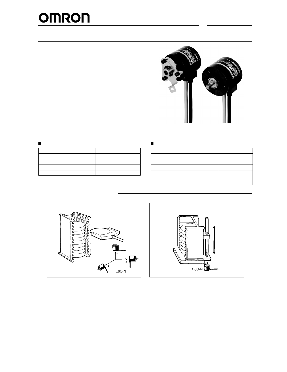
Absolute Rotary Encoder E6C-N
Ideal for the Tripping Detection of
Stepping Motors and the Position
Control of Loaders and Unloaders
<READ AND UNDERSTAND THIS CATALOG>
Please read and understand this catalog before purchasing the
products. Please consult your OMRON representative if you have
any questions or comments.
Ordering Information
Absolute Rotary Encoders
Name Model
Shaft model with cable E6C-NN5C
Hollow-shaft model with cable E6C-NN5CA
Shaft model with connector E6C-NN5C-C
Hollow-shaft model with connector E6C-NN5CA-C
Accessories (Order Separately)
Name Model Remarks
Coupling E69-06B ---
Coupling E69-C06M Metal construction
Flange E69-FCA ---
Flange E69-FCA02 ---
Mounting Bracket E69-2 Provided with
E69-FCA02 Flange
Application Examples
Control of Wafer Transporting Robot Control of Wafer Cassette Movement
Page 2
E6C-N
E6C-N
2
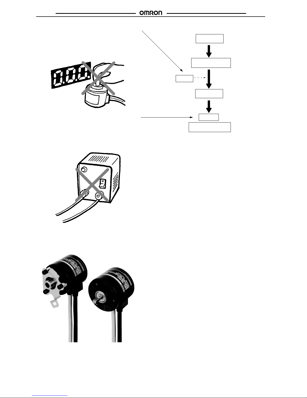
Origin Reset Ensures Easy Origin Setting
after Enclosed Mounting
In addition to the conventional reset function for multi-rotation
data, a reset function for single-rotation data is available, which
ensures easy origin setting of the E6C-N after enclosed mounting and saves the number of steps required for the reset operation.
Data Stored with No Backup Power Supply
Multi-rotation data is stored in the non-volatile built-in memory
at the time of power failure, thus eliminating the need for a conventional backup power supply and simplifying the system configuration. Multi-rotation detection is, however, not possible at
the time of power failure, and multi-rotation data is compensated according to the rotational operation within ±80° of the
position at the time of power failure.
Select from Two Models According to the
Application
Select one suited to the application from a line of shaft and hollow shaft models. The hollow shaft model absorbs the vibration
of the driving axis with the special built-in spring.
Power turned on
Data read from built-in memory
Data output
(data after power turned off)
Data reset
Single-rotation data is output with
the arithmetic operation of absolute codes. Therefore, the reliability of data after reset is ensured.
Power turned off
Data stored in built-in memory
Data storage
Compensating multi-rotation
data within ±80°
Great Cost Reduction
The E6C-N is considerably less expensive than the conventional E6C-M. This was achieved through the use of a plastic
casing and ASIC, the minimization of functions to ones that are
truly useful, and improvements in assembly.
CE Marking
Note: Data: Single-rotation, Multi-rotation data
Page 3

E6C-N
E6C-N
3
Specifications
Ratings/Characteristics
Power supply voltage 12 VDC
–10%
to 24 VDC
+10%
, ripple (p-p): 5% max.
Current consumption 80 mA max.
Resolution
Single-rotation
absolute
500 P/R
Multi-rotation
absolute
–128 to 127 rotations (see note 2)
Rotational limitation at power failure ±80° (see note 3)
Output
Output code Binary code
p
Alarm output Counter Overflow Output (see note 4)
Output configuration NPN open-collector output
Output capacity Applied voltage: 30 VDC max.
I
sink
: 10 mA max. (with 30-mA Counter Overflow Output)
Residual voltage: 0.4 V max.
Logic Negative logic output
Rotational direction Clockwise, as viewed from the face of the shaft.
Input
Input signal Single-rotation data reset and multi-rotation data reset (see note 5)
p
Input current 1 mA max.
Input logic L active, normally open
Input time 100 ms max.
Max. response frequency 12.5 kHz
Rise and fall times of output 1 µs max.
Starting torque
30 gf S cm (2.94 mN S m) max.
Moment of inertia
1.5 x 10⁻⁶ kg S m2 (15 g S cm2) max.
Shaft loading
Radial: 3 kgf (29.4N)
g
Thrust: 2 kgf (19.6N)
Max. permissible rotation 1,500 rpm
Ambient temperature
Operating: –10°C to 55°C with no icing (see note 6)
p
Storage: –25°C to 65°C
Ambient humidity 35% to 85% with no condensation
Insulation resistance 20 MΩ min. (at 100 VDC) between carry parts and case
Dielectric strength 500 VAC, 50/60 Hz for 1 min between carry parts and case
Vibration resistance Destruction: 10 to 500 Hz, 1.0-mm single amplitude or 150 m/s2 (15G) for 11 min, 3 times
each in X, Y, and Z directions
Shock resistance Destruction: 1,000 m/s2 (100G) 3 times each in X, Y, and Z directions
Enclosure rating IEC IP50
Housing material Mechanism: PPS resin
Case: ABS resin
Weight 400 g max. (with 2-m cord)
Note: 1. When the power supply is turned off, all data output is turned off and no data can be input.
2. Multi-rotation absolute negative values are expressed with 2’s complements. Refer to the following list of codes.
3. At the time of power failure, no multi-rotation detection is performed, and multi-rotation data is compensated by comparing the data
values immediately before and after the power fails. Therefore, the accuracy of multi-rotation data will be affected if the power fails
and there is a rotation exceeding ±80° of the position at the time of power failure. Be sure that the rotation is within the specified
range in such cases.
4. Counter Overflow Output will turn ON if the multi-rotation counter exceeds a range between –128 and 127 rotations. This error flag
will be reset if the count returns to a value within the above range.
5. If single- and multi-rotation data reset signals are input, single-rotation data will be reset to address 0 and multi-rotation data is reset
to rotation 0 independently.
6. Be sure that the equipment connected to the Encoder shaft is within the rated operating range.
Page 4

E6C-N
E6C-N
4
Multi-rotation Absolute Value Codes
Multi-rotation
absolute value
Code
10
9
8
7
6
5
4
3
2
1
0
–1
–2
–3
–4
–5
–6
–7
–8
–9
–10
–11
00001010
00001001
00001000
00000111
00000110
00000101
00000100
00000011
00000010
00000001
00000000
11111111
11111110
11111101
11111100
11111011
11111010
11111001
11111000
11110111
11110110
11110101
Note: By replacing values 1 and 0 of a positive value with each
other and adding 1, a negative value is expressed.
Page 5

E6C-N
E6C-N
5
Operation
Connection
E6C-NN5Cj Cable Specifications
Cable color: Gray Cable color: Black
Lead wire color Signal name Description Lead wire color Signal name Description
Brown ABS0
Single-rotation
20Brown TKN0
Multi-rotation
2
0
Orange ABS1
g
absolute data
21Orange TKN1
absolute data
2
1
Yellow ABS2 22Yellow TKN2 2
2
Green ABS3 23Green TKN3 2
3
Blue ABS4 24Blue TKN4 2
4
Purple ABS5 25Purple TKN5 2
5
Gray ABS6 26Gray TKN6 2
6
White ABS7 27White TKN7 2
7
Pink ABS8 28Pink C0F Counter overflow alarm
Light blue ARST Single-rotation data reset Light blue TRST Multi-rotation data reset
Black GND 0 V (see note 2) Black GND 0 V (see note 2)
Red V
CC
12 to 24 VDC (see note 2) Red V
CC
12 to 24 VDC (see note 2)
--- SHIELD Shield --- SHIELD Shield
E6C-NN5Cj-C Connector Specifications
Cable color: Gray Cable color: Black
Pin Signal name Description Pin Signal name Description
A1 ABS0
Single-rotation
20B1 TKN0
Multi-rotation
2
0
A2 ABS1
g
absolute data
21B2 TKN1
absolute data
2
1
A3 ABS2 22B3 TKN2 2
2
A4 ABS3 23B4 TKN3 2
3
A5 ABS4 24B5 TKN4 2
4
A6 ABS5 25B6 TKN5 2
5
A7 ABS6 26B7 TKN6 2
6
A8 ABS7 27B8 TKN7 2
7
A9 ABS8 28B9 C0F Counter overflow alarm
A10 ARST Single-rotation data reset B10 TRST Multi-rotation data reset
A11 GND 0 V (see note 2) B11 GND 0 V (see note 2)
A12 V
CC
12 to 24 VDC (see note 2) B12 V
CC
12 to 24 VDC (see note 2)
A13 SHIELD Shield B13 SHIELD Shield
Note: 1. Connectors:
PS-D4C26 (Hood: PS-HD26) (Nippon Koku Denshi)
Connection connectors:
PS26PE-D4Tj-Mj (straight type) (Nippon Koku
Denshi)
PS-26PE-D4LTj-Mj (angle type) (Nippon Koku
Denshi)
2. It is recommended that both V
CC
lines and GND lines be
connected.
Terminal Arrangement
Page 6

E6C-N
E6C-N
6
Input Circuit Diagram
Main
circuit
Reset input
TRST
ARST
Output Circuit Diagram
Main
circuit
12 to 24 VDC
Output
Shield
Note: The output of each bit shares the same circuit.
Output Mode
Rotational Direction: Clockwise, as viewed from the face of the shaft.
Output transistor
Address
Page 7

E6C-N
E6C-N
7
Dimensions
Note: All units are in millimeters unless otherwise indicated.
E6C-NN5C (with Cable)
E6C-NN5C-C (with Connector)
38 dia.
Three, M4 holes
Depth: 8
6 dia.
25 dia.
50 dia.
6 external dia. PVC, shielded
12-conductor cable (7/0.18 dia.)
E6C-NN5C-C
E6C-NN5CA (with Cable)
E6C-NN5CA-C (with Connector)
Two, M3
8 dia.
14 dia.
50 dia.
6 external dia. PVC, shielded
12-conductor cable (7/0.18 dia.)
E6C-NN5CA-CMounting Dimensions
Center of shaft
Two, M4
Page 8

E6C-N
E6C-N
8
Accessories (Order Separately)
Couplings
E69C-C06B
15 dia.
6H8 dia.
Four, M3 hexagon
set screws
Note: Material: Glass-reinforced PBT
E69-C06M (Metal Construction)
6H8 dia.
19.1 dia.
Four, M3 hexagon
set screws
Note: Material: Super duralumin
Flanges
E69-FCA
Four, 4.5-dia. holes
Three, 4.5 screw-head holes
Note: Material: SPCC, t=3.2
52 x 52
Four, R3
25.2-dia. holes
E69-FCA02
Three, 5.5
screw-head
holes
Note: Material: SPCC, t = 3.2
38 dia.
56 dia.
25.2 dia.
5.5-dia. hole
Mounting Bracket:
(A set of three Brackets provided with the
E69-FCA02)
Mounting Dimensions
Panel
68 dia.
Three, M5
25 dia.
Two, C1
±0.05
0
Servo Mounting Bracket
E69-2 (Set of three)
5.5-dia. hole
Note: A set of E69-2 Servo Mounting
Brackets is provided with the
E69-FCA02 Flange.
Two, C1
Page 9

E6C-N
E6C-N
9
Installation
Connection Example
Connection with CPM1A
E6C-NN5C
CPM1A-40CDj-j
Wiring between E6C-NN5C and CPM1A
E6C-NN5C output signal CPM1A
input signal
Single-rotation
Cable cover
Brown (20) 00000
g
data color (gray)
Orange (21) 00001
Yellow (22) 00002
Green (23) 00003
Blue (24) 00004
Purple (25) 00005
Gray (26) 00006
White (27) 00007
Pink (28) 00008
Multi-rotation
Cable cover
Brown (20) 00100
data color (black)
Orange (21) 00101
Yellow (22) 00102
Green (23) 00103
Blue (24) 00104
Purple (25) 00105
Code + = 0
Gray (26) 00106
– = 1
White (27) 00107
Output Timing
E6C-NN5C’s absolute data
1 rotation 2 rotations 127 rotations
DM Setting
DM 0000
0000
0001
0002
0003
0004
0005
0006
0007
0008
0009
0010
0011
0012
0013 0001
0500
0000
9000
Data program work area
Linear absolute data
Comparison data
Upper-limit setting
Lower-limit setting
Ladder Program Example
ANDW(34)
000
#01FF
D0000
BCD(24)
D0000
D0001
ANDW(34)
001
#007F
D0003
BCD(24)
D0003
D0004
MUL(32)
D0004
#0005
D0005
ADDL(54)
D0001
#0005
D0007
25313
(Always ON)
Transfers only the data of
bits 0 through 8 of word 000
to DM 0000 (single-rotation
BIN data).
Converts single-rotation BIN
data into a BCD code signal.
Transfers only the data of
bits 0 through 7 of word 001
to DM 0003 (multi-rotation
BIN data).
Converts multi-rotation BIN
data into a BCD code signal.
The result of multi-rotation
BCD data x 500 (single-rotation resolution) is input to
DM 0005 and DM 0006.
Adds single-rotation data
and multi-rotation data as
linear absolute data.
CMPL(60)
D0007
D0010
000
CMPL(60)
D0007
D0012
000
25506
25505
(>)
(=)
10000
25506
25507
(<)
(=)
10001
10000 10001
01000
Compares the
band and output
bit 01000 is ON if
linear absolute
data exists between the value of
DM 0010 and
DM 0011 and that
of DM 0012 and
DM 0013. The
band is compared
in the forward
rotational direction
only.
Page 10

E6C-N
E6C-N
10
Precautions
!
WARNING
This product is not designed or rated for ensuring
safety of persons.
Do not use it for such purposes.
Precautions for Safe Use
Do not use the E6C-N at a voltage exceeding the rated voltage
range, otherwise the E6C-N may be damaged.
Do not wire power lines or high-tension lines alongside the lines of
the E6C-N in the same conduit, otherwise the E6C-N may be damaged or malfunction due to induction. Be sure to wire the lines of the
E6C-N separated from power lines or high-tension lines or laid in an
separate, shielded conduit.
Do not make mistakes in wiring, such as mistakes in polarity, otherwise the E6C-N may be damaged.
Be sure that the E6C-N is turned off when wiring, otherwise the output circuit may be damaged if active output line comes in contact
with the power line.
Precautions for Correct Use
If the power supply has surge voltage, connect a surge absorber in
parallel to the power supply to absorb the surge voltage.
To protect the E6C-N from noise interference, be sure that each wire
connected to the E6C-N is as short as possible.
The E6C-N may output a pulse signal when the E6C-N is turned on
or off. Therefore, turn on each device connected to the E6C-N one
second after turning on the E6C-N and turn each device off one second before turning off the E6C-N.
The E6C-N consists of high-precision components. Be sure to handle the E6C-N with care.
• Be sure that the E6C-N is free of water or oil drops.
• Do not short-circuit the load, otherwise the E6C-N may be
damaged.
• If the E6C-N is mounted with a cable wired, do not pull the cable
with a force exceeding 3 kgf (29.4 N).
• The torque required to tighten each screw must be 5 kgf S cm
(0.49 N S m) maximum. Excessive tightening torque may
damage the E6C-N.
• Do not impose excessive loads on the shaft, otherwise the shaft
may be damaged.
Do not directly connect the shaft to chains, timing belts, or gears.
Be sure to connect the shaft through appropriate bearings and
couplings.
• If there is a difference in angle between the shaft and the other
shaft connected, an excessive load that may damage the shaft
will be imposed on the shaft. Be sure that the shaft is connected
properly.
• When inserting the shaft to a coupling, do not strike the shaft or
coupling with a hammer or impose any other shock to the shaft or
coupling.
• When connecting or disconnecting the coupling to or from the
shaft, do not excessively bend, press, or pull the coupling.
Page 11

E6C-N
E6C-N
11
Page 12

WARRANTY
OMRON’s exclusive warranty is that the products are free from defects in materials and workmanship for a period of one year (or other period if
specified) from date of sale by OMRON.
OMRON MAKES NO WARRANTY OR REPRESENTATION, EXPRESS OR IMPLIED, REGARDING NON–INFRINGEMENT,
MERCHANTABILITY, OR FITNESS FOR PARTICULAR PURPOSE OF THE PRODUCTS. ANY BUYER OR USER ACKNOWLEDGES THAT
THE BUYER OR USER ALONE HAS DETERMINED THAT THE PRODUCTS WILL SUITABLY MEET THE REQUIREMENTS OF THEIR
INTENDED USE. OMRON DISCLAIMS ALL OTHER WARRANTIES, EXPRESS OR IMPLIED.
LIMITATIONS OF LIABILITY
OMRON SHALL NOT BE RESPONSIBLE FOR SPECIAL, INDIRECT, OR CONSEQUENTIAL DAMAGES, LOSS OF PROFITS OR
COMMERCIAL LOSS IN ANY WAY CONNECTED WITH THE PRODUCTS, WHETHER SUCH CLAIM IS BASED ON CONTRACT, WARRANTY,
NEGLIGENCE, OR STRICT LIABILITY.
In no event shall responsibility of OMRON for any act exceed the individual price of the product on which liability is asserted.
IN NO EVENT SHALL OMRON BE RESPONSIBLE FOR WARRANTY, REPAIR, OR OTHER CLAIMS REGARDING THE PRODUCTS UNLESS
OMRON’S ANALYSIS CONFIRMS THAT THE PRODUCTS WERE PROPERLY HANDLED, STORED, INSTALLED, AND MAINTAINED AND
NOT SUBJECT TO CONTAMINATION, ABUSE, MISUSE, OR INAPPROPRIATE MODIFICATION OR REPAIR.
SUITABILITY FOR USE
THE PRODUCTS CONTAINED IN THIS DOCUMENT ARE NOT SAFETY RATED. THEY ARE NOT DESIGNED OR RATED FOR ENSURING
SAFETY OF PERSONS, AND SHOULD NOT BE RELIED UPON AS A SAFETY COMPONENT OR PROTECTIVE DEVICE FOR SUCH
PURPOSES. Please refer to separate catalogs for OMRON’s safety rated products.
OMRON shall not be responsible for conformity with any standards, codes, or regulations that apply to the combination of products in the customer’s
application or use of the product.
At the customer’s request, OMRON will provide applicable third party certification documents identifying ratings and limitations of use that apply to
the products. This information by itself is not sufficient for a complete determination of the suitability of the products in combination with the end
product, machine, system, or other application or use.
The following are some examples of applications for which particular attention must be given. This is not intended to be an exhaustive list of all
possible uses of the products, nor is it intended to imply that the uses listed may be suitable for the products:
• Outdoor use, uses involving potential chemical contamination or electrical interference, or conditions or uses not described in this document.
• Nuclear energy control systems, combustion systems, railroad systems, aviation systems, medical equipment, amusement machines, ve-
hicles, safety equipment, and installations subject to separate industry or government regulations.
• Systems, machines, and equipment that could present a risk to life or property.
Please know and observe all prohibitions of use applicable to the products.
NEVER USE THE PRODUCTS FOR AN APPLICATION INVOLVING SERIOUS RISK TO LIFE OR PROPERTY WITHOUT ENSURING THAT
THE SYSTEM AS A WHOLE HAS BEEN DESIGNED TO ADDRESS THE RISKS, AND THAT THE OMRON PRODUCT IS PROPERLY RATED
AND INSTALLED FOR THE INTENDED USE WITHIN THE OVERALL EQUIPMENT OR SYSTEM.
PERFORMANCE DATA
Performance data given in this document is provided as a guide for the user in determining suitability and does not constitute a warranty. It may
represent the result of OMRON’s test conditions, and the users must correlate it to actual application requirements. Actual performance is subject to
the OMRON Warranty and Limitations of Liability.
CHANGE IN SPECIFICATIONS
Product specifications and accessories may be changed at any time based on improvements and other reasons.
It is our practice to change model numbers when published ratings or features are changed, or when significant construction changes are made.
However, some specifications of the product may be changed without any notice. When in doubt, special model numbers may be assigned to fix or
establish key specifications for your application on your request. Please consult with your OMRON representative at any time to confirm actual
specifications of purchased products.
DIMENSIONS AND WEIGHTS
Dimensions and weights are nominal and are not to be used for manufacturing purposes, even when tolerances are shown.
ERRORS AND OMISSIONS
The information in this document has been carefully checked and is believed to be accurate; however, no responsibility is assumed for clerical,
typographical, or proofreading errors, or omissions.
PROGRAMMABLE PRODUCTS
OMRON shall not be responsible for the user’s programming of a programmable product, or any consequence thereof.
OMRON Corporation
Industrial Automation Company
Sensing Devices Division H.Q.
Industrial Sensors Division
Shiokoji Horikawa, Shimogyo-ku,
Kyoto, 600-8530 Japan
Tel: (81)75-344-7022/Fax: (81)75-344-7107
ALL DIMENSIONS SHOWN ARE IN MILLIMETERS.
To convert millimeters into inches, multiply by 0.03937. To convert grams into ounces, multiply by 0.03527.
Cat. No. Q110-E1-02 In the interest of product improvement, specifications are subject to change without notice.
Printed in Japan
0805-0.5C (0997) (M)
 Loading...