

Omron E6C-N DATASHEET
Absolute Rotary Encoder E6C-N
Ideal for the Tripping Detection of
Stepping Motors and the Position
Control of Loaders and Unloaders
<READ AND UNDERSTAND THIS CATALOG>
Please read and understand this catalog before purchasing the
products. Please consult your OMRON representative if you have
any questions or comments.
Ordering Information
Absolute Rotary Encoders
Name Model
Shaft model with cable E6C-NN5C
Hollow-shaft model with cable E6C-NN5CA
Shaft model with connector E6C-NN5C-C
Hollow-shaft model with connector E6C-NN5CA-C
Accessories (Order Separately)
Name Model Remarks
Coupling E69-06B ---
Coupling E69-C06M Metal construction
Flange E69-FCA ---
Flange E69-FCA02 ---
Mounting Bracket E69-2 Provided with
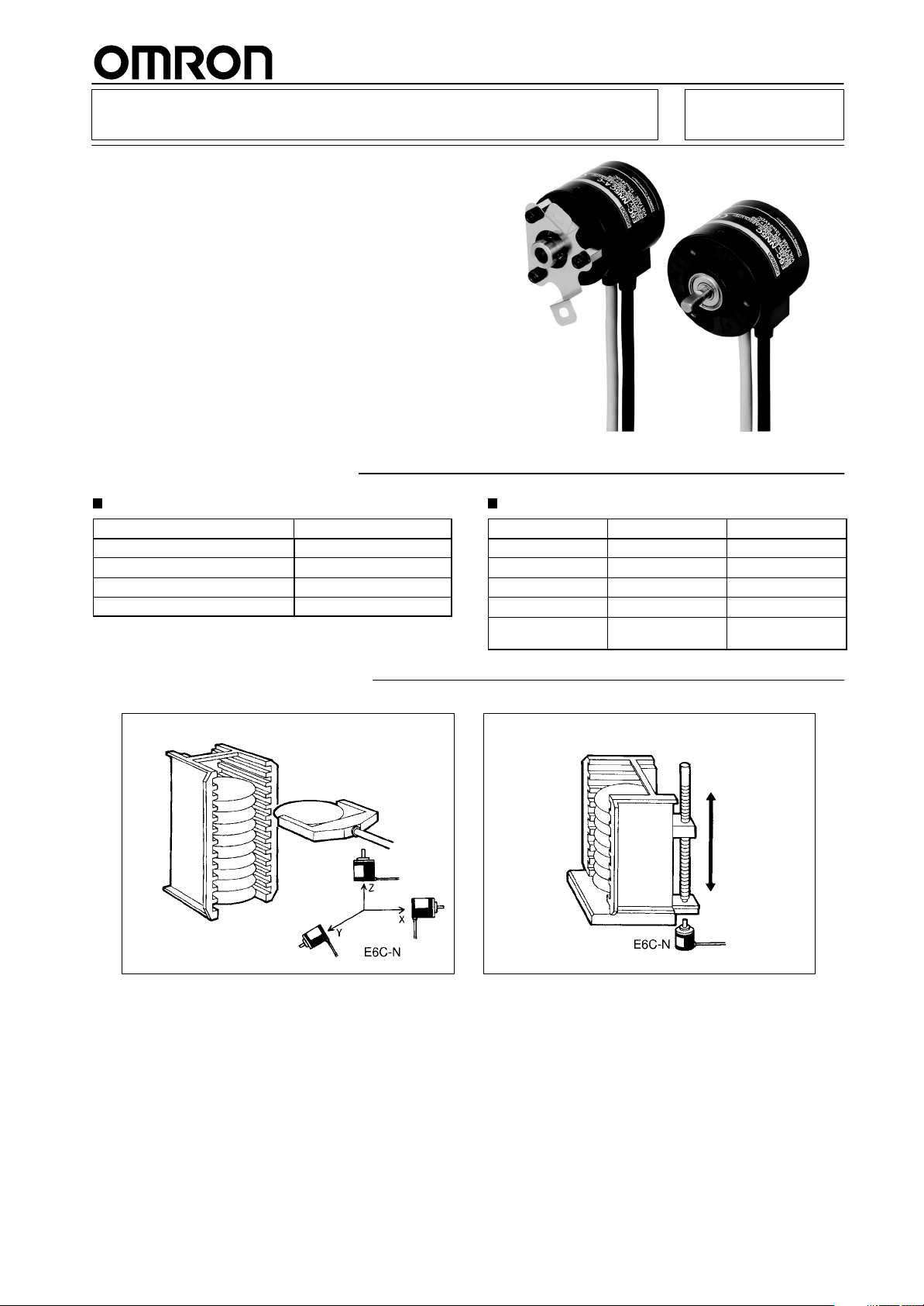
Application Examples
Control of Wafer Transporting Robot Control of Wafer Cassette Movement
E69-FCA02 Flange
1
E6C-N
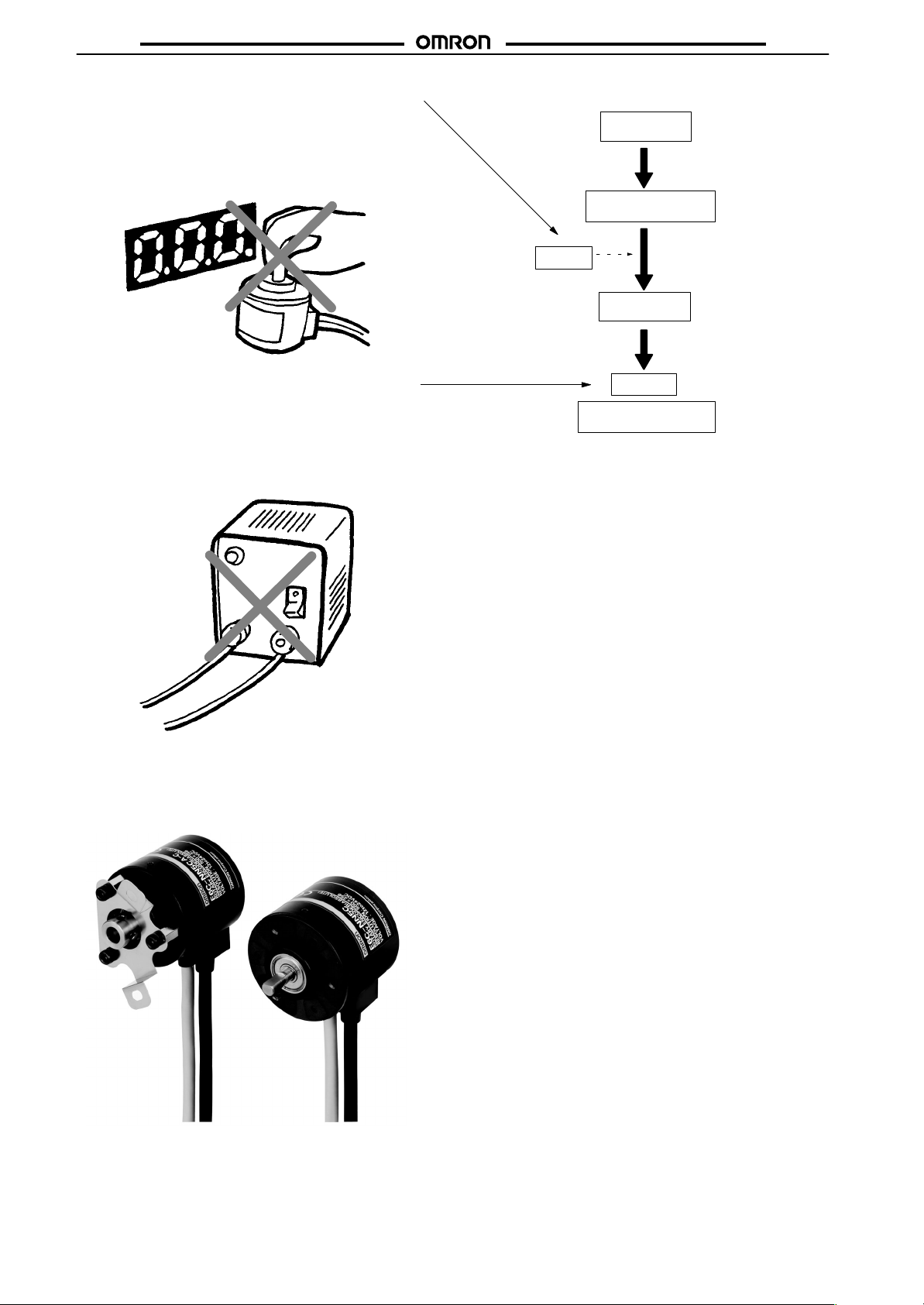
Origin Reset Ensures Easy Origin Setting
after Enclosed Mounting
In addition to the conventional reset function for multi-rotation
data, a reset function for single-rotation data is available, which
ensures easy origin setting of the E6C-N after enclosed mounting and saves the number of steps required for the reset operation.
Data reset
Power turned on
Data read from built-in memory
Data output
(data after power turned off)
Single-rotation data is output with
the arithmetic operation of absolute codes. Therefore, the reliability of data after reset is ensured.
Power turned off
Data stored in built-in memory
E6C-N
Data Stored with No Backup Power Supply
Multi-rotation data is stored in the non-volatile built-in memory
at the time of power failure, thus eliminating the need for a conventional backup power supply and simplifying the system configuration. Multi-rotation detection is, however, not possible at
the time of power failure, and multi-rotation data is compensated according to the rotational operation within ±80° of the
position at the time of power failure.
Select from Two Models According to the
Application
Select one suited to the application from a line of shaft and hollow shaft models. The hollow shaft model absorbs the vibration
of the driving axis with the special built-in spring.
Data storage
Compensating multi-rotation
data within ±80°
Note: Data: Single-rotation, Multi-rotation data
Great Cost Reduction
The E6C-N is considerably less expensive than the conventional E6C-M. This was achieved through the use of a plastic
casing and ASIC, the minimization of functions to ones that are
truly useful, and improvements in assembly.
CE Marking
2

E6C-N
p
p
g
p
E6C-N
Specifications
Ratings/Characteristics
Power supply voltage 12 VDC
Current consumption 80 mA max.
Resolution
Rotational limitation at power failure ±80° (see note 3)
Output
Input
Max. response frequency 12.5 kHz
Rise and fall times of output 1 µs max.
Starting torque
Moment of inertia
Shaft loading
Max. permissible rotation 1,500 rpm
Ambient temperature
Ambient humidity 35% to 85% with no condensation
Insulation resistance 20 MΩ min. (at 100 VDC) between carry parts and case
Dielectric strength 500 VAC, 50/60 Hz for 1 min between carry parts and case
Vibration resistance Destruction: 10 to 500 Hz, 1.0-mm single amplitude or 150 m/s2 (15G) for 11 min, 3 times
Shock resistance Destruction: 1,000 m/s2 (100G) 3 times each in X, Y, and Z directions
Enclosure rating IEC IP50
Housing material Mechanism: PPS resin
Weight 400 g max. (with 2-m cord)
Single-rotation
absolute
Multi-rotation
absolute
Output code Binary code
Alarm output Counter Overflow Output (see note 4)
Output configuration NPN open-collector output
Output capacity Applied voltage: 30 VDC max.
Logic Negative logic output
Rotational direction Clockwise, as viewed from the face of the shaft.
Input signal Single-rotation data reset and multi-rotation data reset (see note 5)
Input current 1 mA max.
Input logic L active, normally open
Input time 100 ms max.
–10%
to 24 VDC
500 P/R
–128 to 127 rotations (see note 2)
I
: 10 mA max. (with 30-mA Counter Overflow Output)
sink
Residual voltage: 0.4 V max.
30 gf S cm (2.94 mN S m) max.
1.5 x 10⁻⁶ kg S m2 (15 g S cm2) max.
Radial: 3 kgf (29.4N)
Thrust: 2 kgf (19.6N)
Operating: –10°C to 55°C with no icing (see note 6)
Storage: –25°C to 65°C
each in X, Y, and Z directions
Case: ABS resin
+10%
, ripple (p-p): 5% max.
Note: 1. When the power supply is turned off, all data output is turned off and no data can be input.
2. Multi-rotation absolute negative values are expressed with 2’s complements. Refer to the following list of codes.
3. At the time of power failure, no multi-rotation detection is performed, and multi-rotation data is compensated by comparing the data
values immediately before and after the power fails. Therefore, the accuracy of multi-rotation data will be affected if the power fails
and there is a rotation exceeding ±80° of the position at the time of power failure. Be sure that the rotation is within the specified
range in such cases.
4. Counter Overflow Output will turn ON if the multi-rotation counter exceeds a range between –128 and 127 rotations. This error flag
will be reset if the count returns to a value within the above range.
5. If single- and multi-rotation data reset signals are input, single-rotation data will be reset to address 0 and multi-rotation data is reset
to rotation 0 independently.
6. Be sure that the equipment connected to the Encoder shaft is within the rated operating range.
3

E6C-N
Multi-rotation Absolute Value Codes
Multi-rotation
absolute value
10
9
8
7
6
5
4
3
2
1
0
–1
–2
–3
–4
–5
–6
–7
–8
–9
–10
–11
Note: By replacing values 1 and 0 of a positive value with each
other and adding 1, a negative value is expressed.
Code
00001010
00001001
00001000
00000111
00000110
00000101
00000100
00000011
00000010
00000001
00000000
11111111
11111110
11111101
11111100
11111011
11111010
11111001
11111000
11110111
11110110
11110101
E6C-N
4
 Loading...