


Cat. No. H078-E1-03C
E5CK
Digital Controller
USER’S MANUAL

E5CK
Digital Controller
User's Manual
Cat. No. H078-E1-03C

Terms and Conditions of Sale
1. Offer; Acceptance. These terms and conditions (these "Terms") are deemed
part of all quotes, agreements, purchase orders, acknowledgments, price lists,
catalogs, manuals, brochures and other documents, whether electronic or in
writing, relating to the sale of products or services (collectively, the "Products
by Omron Electronics LLC and its subsidiary companies (“Omron
objects to any terms or conditions proposed in Buyer’s purchase order or other
documents which are inconsistent with, or in addition to, these Terms.
2. Prices; Payment Terms.
out notice by Omron. Omron reserves the right to increase or decrease prices
on any unshipped portions of outstanding orders. Payments for Products are
due net 30 days unless otherwise stated in the invoice.
3. Discounts.
sent to Buyer after deducting transportation charges, taxes and duties, and will
be allowed only if (i) the invoice is paid according to Omron’s payment terms
and (ii) Buyer has no past due amounts.
4. Interest.
the maximum legal rate, whichever is less, on any balance not paid within the
stated terms.
5. Orders
6. Governmental Approvals.
costs involved in, obtaining any government approvals required for the importation or sale of the Products.
7. Taxes
real property and income taxes), including any interest or penalties thereon,
imposed directly or indirectly on Omron or required to be collected directly or
indirectly by Omron for the manufacture, production, sale, delivery, importation, consumption or use of the Products sold hereunder (including customs
duties and sales, excise, use, turnover and license taxes) shall be charged to
and remitted by Buyer to Omron.
8. Financial.
to Omron, Omron reserves the right to stop shipments or require satisfactory
security or payment in advance. If Buyer fails to make payment or otherwise
comply with these Terms or any related agreement, Omron may (without liability and in addition to other remedies) cancel any unshipped portion of Products sold hereunder and stop any Products in transit until Buyer pays all
amounts, including amounts payable hereunder, whether or not then due,
which are owing to it by Buyer. Buyer shall in any event remain liable for all
unpaid accounts.
9. Cancellation; Etc.
unless Buyer indemnifies Omron against all related costs or expenses.
10. Force Majeure
resulting from causes beyond its control, including earthquakes, fires, floods,
strikes or other labor disputes, shortage of labor or materials, accidents to
machinery, acts of sabotage, riots, delay in or lack of transportation or the
requirements of any government authority.
11. Shipping; Delivery.
a. Shipments shall be by a carrier selected by Omron; Omron will not drop ship
b. Such carrier shall act as the agent of Buyer and delivery to such carrier shall
c. All sales and shipments of Products shall be FOB shipping point (unless oth-
d. Delivery and shipping dates are estimates only; and
e. Omron will package Products as it deems proper for protection against nor-
12. Claims.
Products occurring before delivery to the carrier must be presented in writing
to Omron within 30 days of receipt of shipment and include the original transportation bill signed by the carrier noting that the carrier received the Products
from Omron in the condition claimed.
13. Warranties
Products will be free from defects in materials and workmanship for a period of
twelve months from the date of sale by Omron (or such other period expressed
in writing by Omron). Omron disclaims all other warranties, express or implied.
(b) Limitations
EXPRESS OR IMPLIED, ABOUT NON-INFRINGEMENT, MERCHANTABIL-
Cash discounts, if any, will apply only on the net amount of invoices
Omron, at its option, may charge Buyer 1-1/2% interest per month or
. Omron will accept no order less than $200 net billing.
. All taxes, duties and other governmental charges (other than general
If the financial position of Buyer at any time becomes unsatisfactory
except in “break down” situations.
constitute delivery to Buyer;
erwise stated in writing by Omron), at which point title and risk of loss shall
pass from Omron to Buyer; provided that Omron shall retain a security interest in the Products until the full purchase price is paid;
mal handling and extra charges apply to special conditions.
Any claim by Buyer against Omron for shortage or damage to the
. (a) Exclusive Warranty. Omron’s exclusive warranty is that the
All prices stated are current, subject to change with-
Buyer shall be responsible for, and shall bear all
Orders are not subject to rescheduling or cancellation
. Omron shall not be liable for any delay or failure in delivery
Unless otherwise expressly agreed in writing by Omron:
. OMRON MAKES NO WARRANTY OR REPRESENTATION,
”). Omron
ITY OR FITNESS FOR A PARTICULAR PURPOSE OF THE PRODUCTS.
BUYER ACKNOWLEDGES THAT IT ALONE HAS DETERMINED THAT THE
PRODUCTS WILL SUITABLY MEET THE REQUIREMENTS OF THEIR
")
INTENDED USE. Omron further disclaims all warranties and responsibility of
any type for claims or expenses based on infringement by the Products or otherwise of any intellectual property right. (c) Buyer Remedy
gation hereunder shall be, at Omron’s election, to (i) replace (in the form
originally shipped with Buyer responsible for labor charges for removal or
replacement thereof) the non-complying Product, (ii) repair the non-complying
Product, or (iii) repay or credit Buyer an amount equal to the purchase price of
the non-complying Product; provided that in no event shall Omron be responsible for warranty, repair, indemnity or any other claims or expenses regarding
the Products unless Omron’s analysis confirms that the Products were properly handled, stored, installed and maintained and not subject to contamination, abuse, misuse or inappropriate modification. Return of any Products by
Buyer must be approved in writing by Omron before shipment. Omron Companies shall not be liable for the suitability or unsuitability or the results from the
use of Products in combination with any electrical or electronic components,
circuits, system assemblies or any other materials or substances or environments. Any advice, recommendations or information given orally or in writing,
are not to be construed as an amendment or addition to the above warranty.
See http://oeweb.omron.com or contact your Omron representative for published information.
14. Limitation on Liability; Etc
FOR SPECIAL, INDIRECT, INCIDENTAL, OR CONSEQUENTIAL DAMAGES,
LOSS OF PROFITS OR PRODUCTION OR COMMERCIAL LOSS IN ANY
WAY CONNECTED WITH THE PRODUCTS, WHETHER SUCH CLAIM IS
BASED IN CONTRACT, WARRANTY, NEGLIGENCE OR STRICT LIABILITY.
Further, in no event shall liability of Omron Companies exceed the individual
price of the Product on which liability is asserted.
15. Indemnities
their employees from and against all liabilities, losses, claims, costs and
expenses (including attorney's fees and expenses) related to any claim, investigation, litigation or proceeding (whether or not Omron is a party) which arises
or is alleged to arise from Buyer's acts or omissions under these Terms or in
any way with respect to the Products. Without limiting the foregoing, Buyer (at
its own expense) shall indemnify and hold harmless Omron and defend or settle any action brought against such Companies to the extent based on a claim
that any Product made to Buyer specifications infringed intellectual property
rights of another party.
16. Property; Confidentiality.
sive property of Omron Companies and Buyer shall not attempt to duplicate it
in any way without the written permission of Omron. Notwithstanding any
charges to Buyer for engineering or tooling, all engineering and tooling shall
remain the exclusive property of Omron. All information and materials supplied
by Omron to Buyer relating to the Products are confidential and proprietary,
and Buyer shall limit distribution thereof to its trusted employees and strictly
prevent disclosure to any third party.
17. Export Controls.
licenses regarding (i) export of products or information; (iii) sale of products to
“forbidden” or other proscribed persons; and (ii) disclosure to non-citizens of
regulated technology or information.
18. Miscellaneous
and no course of dealing between Buyer and Omron shall operate as a waiver
of rights by Omron. (b) Assignment
without Omron's written consent. (c) Law.
law of the jurisdiction of the home office of the Omron company from which
Buyer is purchasing the Products (without regard to conflict of law principles). (d) Amendment
Buyer and Omron relating to the Products, and no provision may be changed
or waived unless in writing signed by the parties. (e) Severability
sion hereof is rendered ineffective or invalid, such provision shall not invalidate
any other provision. (f) Setoff
against the amount owing in respect of this invoice. (g) Definitions
herein, “including” means “including without limitation”; and “Omron Companies” (or similar words) mean Omron Corporation and any direct or indirect
subsidiary or affiliate thereof.
. Buyer shall indemnify and hold harmless Omron Companies and
Buyer shall comply with all applicable laws, regulations and
. (a) Waiver. No failure or delay by Omron in exercising any right
. OMRON COMPANIES SHALL NOT BE LIABLE
Any intellectual property in the Products is the exclu-
. Buyer may not assign its rights hereunder
These Terms are governed by the
. These Terms constitute the entire agreement between
. Buyer shall have no right to set off any amounts
. Omron’s sole obli-
. If any provi-
. As used
Certain Precautions on Specifications and Use
1. Suitability of Use. Omron Companies shall not be responsible for conformity
with any standards, codes or regulations which apply to the combination of the
Product in the Buyer’s application or use of the Product. At Buyer’s request,
Omron will provide applicable third party certification documents identifying
ratings and limitations of use which apply to the Product. This information by
itself is not sufficient for a complete determination of the suitability of the Product in combination with the end product, machine, system, or other application
or use. Buyer shall be solely responsible for determining appropriateness of
the particular Product with respect to Buyer’s application, product or system.
Buyer shall take application responsibility in all cases but the following is a
non-exhaustive list of applications for which particular attention must be given:
(i) Outdoor use, uses involving potential chemical contamination or electrical
interference, or conditions or uses not described in this document.
(ii) Use in consumer products or any use in significant quantities.
(iii) Energy control systems, combustion systems, railroad systems, aviation
systems, medical equipment, amusement machines, vehicles, safety equipment, and installations subject to separate industry or government regulations.
(iv) Systems, machines and equipment that could present a risk to life or property. Please know and observe all prohibitions of use applicable to this Product.
NEVER USE THE PRODUCT FOR AN APPLICATION INVOLVING SERIOUS
RISK TO LIFE OR PROPERTY OR IN LARGE QUANTITIES WITHOUT
ENSURING THAT THE SYSTEM AS A WHOLE HAS BEEN DESIGNED TO
ADDRESS THE RISKS, AND THAT THE OMRON’S PRODUCT IS PROPERLY RATED AND INSTALLED FOR THE INTENDED USE WITHIN THE
OVERALL EQUIPMENT OR SYSTEM.
2. Programmable Products.
user’s programming of a programmable Product, or any consequence thereof.
3. Performance Data
and other materials is provided as a guide for the user in determining suitability and does not constitute a warranty. It may represent the result of Omron’s
test conditions, and the user must correlate it to actual application requirements. Actual performance is subject to the Omron’s Warranty and Limitations
of Liability.
4. Change in Specifications
changed at any time based on improvements and other reasons. It is our practice to change part numbers when published ratings or features are changed,
or when significant construction changes are made. However, some specifications of the Product may be changed without any notice. When in doubt, special part numbers may be assigned to fix or establish key specifications for
your application. Please consult with your Omron’s representative at any time
to confirm actual specifications of purchased Product.
5. Errors and Omissions.
checked and is believed to be accurate; however, no responsibility is assumed
for clerical, typographical or proofreading errors or omissions.
Omron Companies shall not be responsible for the
. Data presented in Omron Company websites, catalogs
. Product specifications and accessories may be
Information presented by Omron Companies has been


Preface
Thank you for your purchase of your E5CK compact, intelligent digital controller.
The E5CK allows the user to carry out the following:
• Select from many types of temperature and analog input (multiple input)
• Select output functions such as control output or alarm (output assignment)
• Use two setpoints (multiĆSP function)
• Monitor the control loop by LBA (Loop Break Alarm)
• Use the communications function
• Calibrate input or transfer output
• It also features a watertight construction (NEMA4: equivalent to IP66)
This User's Manual describes how to use the E5CK compact, highĆfunction digital conĆ
troller.
Before using your E5CK, thoroughly read and understand this manual in order to
ensure correct use.
About this manual
E OMRON, 1995
(1) All rights reserved. No part of this publication may be reproduced, stored in a retrieval system, or transmitted,
in any form, or by any means, mechanical, electronic, photocopying, recording, recording, or otherwise, without
the prior written permission of OMRON.
(2) No patent liability is assumed with respect to the use of the information contained herein.
(3) Moreover, because OMRON is constantly striving to improve its high-quality products, the information in this
manual is subject to change without notice. Every precaution has been taken in the preparation of this manual.
Nevertheless, OMRON assumes no responsibility for errors or omissions. Neither is any liability assumed for
damages resulting from the use of the information contained in this publication.
I

Conventions Used in This Manual
JHow to Read Display Symbols
The following tables show the correspondence between the symbols displayed on the displays
and alphabet characters.
ABCDEFGH I JKLM
NOPQRSTUVWXY Z
J“Reference” mark
This mark indicates that extra, useful information follows, such as supplementary explanations
and how to apply functions.
JNotice:
OMRON products are manufactured for use according to proper procedures by a qualified operaĆ
tor and only for the purposes described in this manual.
The following conventions are used to indicate and classify precautions in this manual. Always
heed the information provided with them. Failure to heed precautions can result in injury to
people or damage to the product.
DANGER
WARNING
Caution
Indicates information that, if not heeded, is likely to result in loss of life
or serious injury.
Indicates information that, if not heeded, could possibly result in loss
of life or serious injury.
Indicates information that, if not heeded, could result in relatively seriĆ
ous or minor injury, damage to the product, or faulty operation.
JOMRON Product References
All OMRON products are capitalized in this manual. The word Unit" is also capitalized when
it refers to an OMRON product, regardless of whether or not it appears in the proper name of
the product.
The abbreviation Ch," which appears in some displays and on some OMRON products, often
means word" and is abbreviated Wd" in documentation in this sense.
The abbreviation PC" means Programmable Controller and is not used as an abbreviation for
anything else.
II

JHow this Manual is Organized
Purpose Title Description
Learning about the general features of the E5CK
Chapter 1 Introduction This chapter describes the feaĆ
tures of the E5CK, names of
parts, and typical functions.
Setting up the E5CK
Basic E5CK operations
Applied E5CK operations
Communications with a
host computer
Calibration
Chapter 2 Preparations This chapter describes the operaĆ
tions that you must carry out
(e.g. installation, wiring and
switch settings) before you can
use the E5CK.
Chapter 3 Basic Operation
Chapter 5 Parameters
Chapter 4 Applied Operation
Chapter 5 Parameters
Chapter 6 Using the CommuĆ
nications Function
Chapter 4 Applied Operation
/ 4.5 Calibration
These chapters describe how to
use the front panel keys and how
to view the display when setting
the parameters of the major funcĆ
tions for the E5CK.
These chapters describe the
important functions of the E5CK
and how to use the parameters
for making full use of the E5CK.
This chapter mainly describes
the communications commands,
and gives program examples.
This chapter describes how the
user should calibrate the E5CK.
Troubleshooting
Chapter 7 Troubleshooting This chapter describes what to do
if any problems occur.
III

Pay Attention to the Following when Installing
this Controller
F If you remove the controller from its case, never touch nor apply shock to the electronic
parts inside.
F Do not cover the top and bottom of the controller. (Ensure sufficient space around the
controller to allow heat to escape.)
F Use a voltage (AC100Ć240V
scribed voltage level must be attained within two seconds.
F When wiring input or output lines to your controller, keep the following points in mind
to reduce the influence from inductive noise:
Ă• Allow adequate space between the high voltage/current power lines and the input/outĆ
put lines.
Ă• Avoid parallel or common wiring with high voltage sources and power lines carrying
large currents.
Ă• Using separating pipes, duct, and shielded line is also useful in protecting the controller,
and its lines form inductive noise.
F Allow as much space as possible between the controller and devices that generate a powĆ
erful, high frequency (highĆfrequency welders, highĆfrequency sewing machines, and so
forth) or surge. These devices may cause malfunctions.
F If there is a large powerĆgenerating peripheral device and any of its lines, attach a surge
suppressor or noise filter to the device to stop the noise affecting the controller system.
In particular, motors, transformers, solenoids and magnetic coils have an inductance
component, and therefore can generate very strong noises.
F When mounting a noise filter, be sure to first check the filter's voltage and current
capacity, then mount the filter as close as possible to the controller.
F Do not use the controller in places where icing, condensation, dust, corrosive gas (espeĆ
cially sulfurized gas or ammonia gas), shock, vibration, splashing liquid, or oil atmoĆ
sphere occur. Also, avoid places where the controller can be subjected to intense heat
radiation (like from a furnace) or sudden temperature changes.
or AC/DC24V at 50 to 60 Hz). At power ON, the preĆ
IV
F Ambient temperature must be kept between Ć10_C to 55_C. Ambient humidity must be
kept between 35%RH to 85%RH (with no icing or condensation). If the controller is
installed inside a control board, the ambient temperature must be kept under 55_C,
including the temperature around the controller. If the controller is subjected to heat
radiation, use a fan to cool the surface of the controller to under 55_C.
F Store the controller at an ambient temperature between Ć25_C to 65_C. The ambient
humidity must be between 35%RH to 85%RH (with no icing or condensation).
F Never place heavy objects on, or apply pressure to the controller that may cause it to
deform and deterioration during use or storage.
F Avoid using the controller in places near a radio, television set, or wireless installation.
These devices can cause radio disturbances which adversely affect the performance of
the controller.

Table of Contents
Preface I. . . . . . . . . . . . . . . . . . . . . . . . . . . . . . . . . . . . . .
Conventions Used in This Manual II. . . . . . . . . . . . . . .
Pay Attention to the Following when Installing
this Controller IV. . . . . . . . . . . . . . . . . . . . . . . . . . . . . . . . .
CHAPTER 1 INTRODUCTION 1–1. . . . . . . . . . . . . . . . . . . . . . . . . .
This chapter introduces the E5CK. First-time users should read this chapter without fail.
For details on how to use the controller and parameter settings, see Chapters 2
onwards.
1.1 Names of parts 1–2. . . . . . . . . . . . . . . . . . . . . . . . . . . . . . . . . . . . . . . . . .
1.2 Input and Output 1–4. . . . . . . . . . . . . . . . . . . . . . . . . . . . . . . . . . . . . . . . .
1.3 Parameters and Menus 1–6. . . . . . . . . . . . . . . . . . . . . . . . . . . . . . . . . . .
1.4 About the Communications Function 1–9. . . . . . . . . . . . . . . . . . . . . . .
1.5 About Calibration 1–10. . . . . . . . . . . . . . . . . . . . . . . . . . . . . . . . . . . . . . . .
CHAPTER 2 PREPARATIONS 2–1. . . . . . . . . . . . . . . . . . . . . . . . . .
This chapter describes the operations you should carry out before turning the
E5CK ON.
2.1 Setting up 2–2. . . . . . . . . . . . . . . . . . . . . . . . . . . . . . . . . . . . . . . . . . . . . . .
2.2 Installation 2–4. . . . . . . . . . . . . . . . . . . . . . . . . . . . . . . . . . . . . . . . . . . . . .
2.3 Wiring Terminals 2–6. . . . . . . . . . . . . . . . . . . . . . . . . . . . . . . . . . . . . . . . .
CHAPTER 3 BASIC OPERATION 3–1. . . . . . . . . . . . . . . . . . . . . . . .
This chapter describes an actual example for understanding the basic operation
of the E5CK.
3.1 Control Example 3–2. . . . . . . . . . . . . . . . . . . . . . . . . . . . . . . . . . . . . . . . .
3.2 Setting Input Specifications 3–3. . . . . . . . . . . . . . . . . . . . . . . . . . . . . . .
3.3 Setting Output Specifications 3–5. . . . . . . . . . . . . . . . . . . . . . . . . . . . . .
3.4 Setting Alarm Type 3–7. . . . . . . . . . . . . . . . . . . . . . . . . . . . . . . . . . . . . . .
3.5 Protect Mode 3–10. . . . . . . . . . . . . . . . . . . . . . . . . . . . . . . . . . . . . . . . . . . .
3.6 Starting and Stopping Operation 3–11. . . . . . . . . . . . . . . . . . . . . . . . . . .
3.7 Adjusting Control Operation 3–12. . . . . . . . . . . . . . . . . . . . . . . . . . . . . . .
CHAPTER 4 APPLIED OPERATION 4–1. . . . . . . . . . . . . . . . . . . . .
This chapter describes each of the parameters required for making full use of the
features of the E5CK. Read this chapter while referring to the parameter descriptions in chapter 5.
4.1 Selecting the Control Method 4–2. . . . . . . . . . . . . . . . . . . . . . . . . . . . . .
4.2 Operating Condition Restrictions 4–4. . . . . . . . . . . . . . . . . . . . . . . . . . .
4.3 How to Use Option Functions 4–7. . . . . . . . . . . . . . . . . . . . . . . . . . . . .
4.4 LBA 4–9. . . . . . . . . . . . . . . . . . . . . . . . . . . . . . . . . . . . . . . . . . . . . . . . . . . .
4.5 Calibration 4–11. . . . . . . . . . . . . . . . . . . . . . . . . . . . . . . . . . . . . . . . . . . . . .

CHAPTER 5 PARAMETERS 5–1. . . . . . . . . . . . . . . . . . . . . . . . . . . .
This chapter describes the parameters of the E5CK. Use this chapter as a reference guide.
Conventions Used in this Chapter 5–2. . . . . . . . . . . . . . . . . . . . . . . . . . . . . .
Protect Mode 5–3. . . . . . . . . . . . . . . . . . . . . . . . . . . . . . . . . . . . . . . . . . . . . . . .
Manual Mode 5–5. . . . . . . . . . . . . . . . . . . . . . . . . . . . . . . . . . . . . . . . . . . . . . . .
Level 0 Mode 5–6. . . . . . . . . . . . . . . . . . . . . . . . . . . . . . . . . . . . . . . . . . . . . . . .
Level 1 Mode 5–9. . . . . . . . . . . . . . . . . . . . . . . . . . . . . . . . . . . . . . . . . . . . . . . .
Level 2 Mode 5–15. . . . . . . . . . . . . . . . . . . . . . . . . . . . . . . . . . . . . . . . . . . . . . . .
Setup Mode 5–21. . . . . . . . . . . . . . . . . . . . . . . . . . . . . . . . . . . . . . . . . . . . . . . . .
Expansion Mode 5–27. . . . . . . . . . . . . . . . . . . . . . . . . . . . . . . . . . . . . . . . . . . . .
Option Mode 5–32. . . . . . . . . . . . . . . . . . . . . . . . . . . . . . . . . . . . . . . . . . . . . . . . .
Calibration Mode 5–36. . . . . . . . . . . . . . . . . . . . . . . . . . . . . . . . . . . . . . . . . . . . .
CHAPTER 6 USING THE COMMUNICATIONS FUNCTION 6–1.
This chapter mainly describes communications with a host computer and communications commands.
6.1 Outline of the Communications Function 6–2. . . . . . . . . . . . . . . . . . . .
6.2 Preparing for Communications 6–3. . . . . . . . . . . . . . . . . . . . . . . . . . . .
6.3 Command Configuration 6–5. . . . . . . . . . . . . . . . . . . . . . . . . . . . . . . . . .
6.4 Commands and Responses 6–6. . . . . . . . . . . . . . . . . . . . . . . . . . . . . . .
6.5 How to Read Communications Error Information 6–10. . . . . . . . . . . . .
6.6 Program Example 6–12. . . . . . . . . . . . . . . . . . . . . . . . . . . . . . . . . . . . . . .
CHAPTER 7 TROUBLESHOOTING 7–1. . . . . . . . . . . . . . . . . . . . . .
This chapter describes how to find out and remedy the cause if the E5CK does
not function properly.
7.1 Initial Checks 7–2. . . . . . . . . . . . . . . . . . . . . . . . . . . . . . . . . . . . . . . . . . . .
7.2 How to Use the Error Display 7–3. . . . . . . . . . . . . . . . . . . . . . . . . . . . . .
7.3 How to Use Error Output 7–5. . . . . . . . . . . . . . . . . . . . . . . . . . . . . . . . . .
7.4 Checking Operation Restrictions 7–6. . . . . . . . . . . . . . . . . . . . . . . . . . .
APPENDIX
SPECIFICATIONS A–2. . . . . . . . . . . . . . . . . . . . . . . .
CONTROL BLOCK DIAGRAM A–5. . . . . . . . . . . . . .
SETTING LIST A–6. . . . . . . . . . . . . . . . . . . . . . . . . . .
PARAMETER OPERATIONS LIST A–8. . . . . . . . . .
FUZZY SELF–TUNING A–10. . . . . . . . . . . . . . . . . . . .
MODEL LIST A–13. . . . . . . . . . . . . . . . . . . . . . . . . . . . .
X FORMAT A–14. . . . . . . . . . . . . . . . . . . . . . . . . . . . . . .
ASCII CODE LIST A–17. . . . . . . . . . . . . . . . . . . . . . . .
INDEX
REVISION HISTORY

CHAPTER1
CHAPTER 1
INTRODUCTION
This chapter introduces the E5CK. FirstĆtime users should read this
chapter without fail.
For details on how to use the controller and parameter settings, see
Chapters 2 onwards.
CHAPTER 1 INTRODUCTION
1.1 Names of parts 1-2. . . . . . . . . . . . . . . . . . . . . . . .
Main parts 1-2. . . . . . . . . . . . . . . . . . . . . . . . . . . .
Front panel 1-2. . . . . . . . . . . . . . . . . . . . . . . . . . .
About the displays 1-3. . . . . . . . . . . . . . . . . . . . .
How to use keys 1-3. . . . . . . . . . . . . . . . . . . . . . .
1.2 Input and Output 1-4. . . . . . . . . . . . . . . . . . . . . .
Input 1-4. . . . . . . . . . . . . . . . . . . . . . . . . . . . . . . . .
Output 1-5. . . . . . . . . . . . . . . . . . . . . . . . . . . . . . . .
1.3 Parameters and Menus 1-6. . . . . . . . . . . . . . . . .
Parameter types 1-6. . . . . . . . . . . . . . . . . . . . . . .
Selecting modes 1-7. . . . . . . . . . . . . . . . . . . . . . . .
Selecting parameters 1-8. . . . . . . . . . . . . . . . . . .
Fixing settings 1-8. . . . . . . . . . . . . . . . . . . . . . . . .
1.4 About the Communications Function 1-9. . . .
1.5 About Calibration 1-10. . . . . . . . . . . . . . . . . . . . . .
1–1

CHAPTER 1 INTRODUCTION
1.1 Names of parts
JMain parts
Terminals
P 2-6
Output unit
P 2-3
Rear case
Input type jumper
connector
JFront panel
Operation indicators
OUT1
OUT2
SUB1
MANU
STOP
RMT
AT
A/M key
A/M
P 2-2
Option unit
P 2-3
PV
SV
OUT1
OUT2 MANU STOP RMT AT SUB1
A
M
E5CK
Front panel
No.1 display
No.2 display
1–2
Display key Down key Up key

JAbout the displays
1.1 Names of parts
F No.1 display
F No.2 display
F Operation indica-
tors
JHow to use keys
A/M
F key
F key
Displays the process value or parameter symbols.
Displays the set point, manipulated variable or parameter settings.
Ă• OUT1 : Lits when the pulsed output function assigned to “control
output 1" is ON.
Ă• OUT2 : Lits when the output function assigned to “control output 2"
is ON.
Ă• SUB1 : Lits when the output function assigned to “auxiliary output
1" is ON.
Ă• MANU : Lits in the manual operation mode.
Ă• STOP : Lits when operation has stopped.
Ă• RMT : Lits during remote operation.
Ă• AT : Flashes during autoĆtuning.
The following describes basic key operations.
Each press of this key switches between the auto and manual operations.
The functions of this key change according to how long it is pressed. If the
key is pressed for less than one second, the parameters are switched. If the
key is pressed for one second or more, the menu display appears. In key
operations from here on, “press the key" refers to pressing the key for less
than one second.
For details on parameter switching and menu display items, see page 1-7.
F key
Each press of the
on the No.2 display, while each press of the
the values or settings on the No.2 display.
Functions vary, for example, when the
neously with the display key, or a key is held down continuously. For
details, see page 1Ć7. Also, chapters 3 and 4 describe examples using variĆ
ous key combinations.
key increments or advances the values or settings
key decrements or returns
A/M
key is held down simultaĆ
1–3
CHAPTER 1 INTRODUCTION
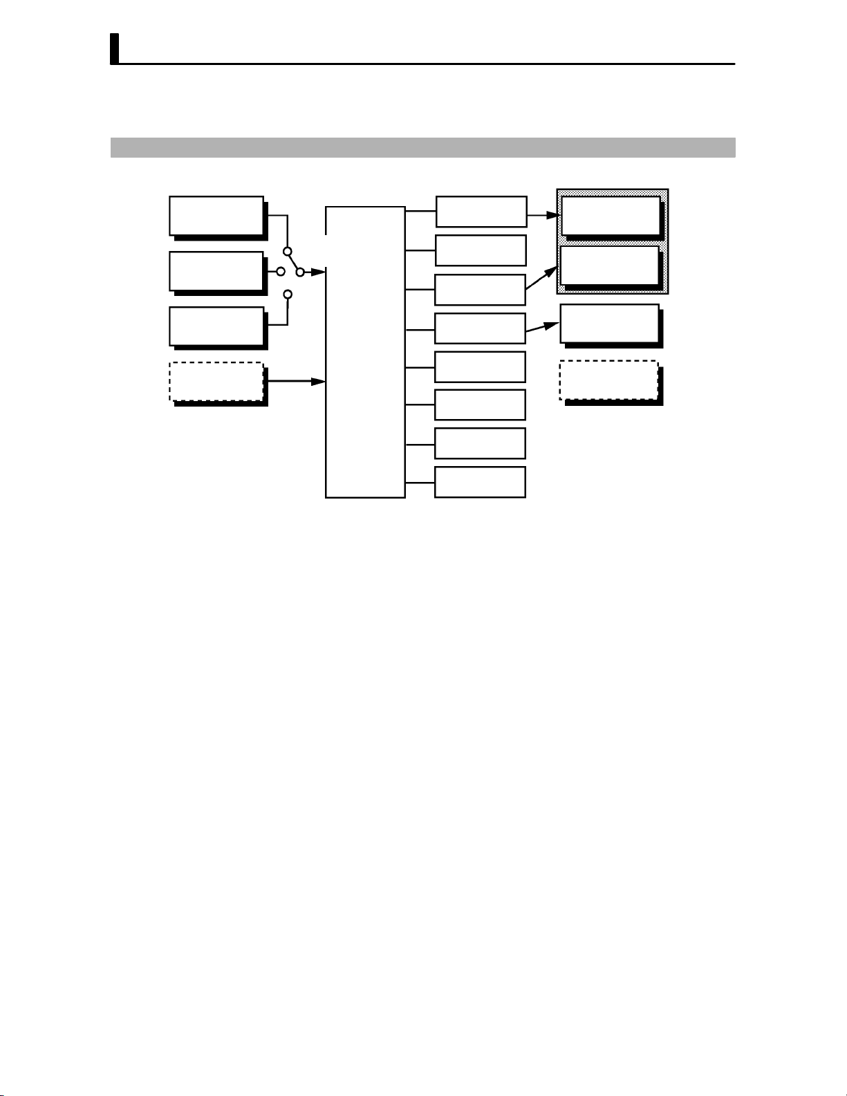
1.2 Input and Output
Control output
(heat)
Control output
(cool)
JInput
Temperature
input
Voltage input
Current input
Event input
Controller
Input type
jumper
The E5CK supports four inputs.
F Temperature input/Voltage input/Current input
Ă• Only one of temperature input, voltage input and current input can be
selected and connected to the controller. The above figure shows temperĆ
ature input connected to the controller.
Ă• The following input sensors can be connected for temperature input:
Thermocouple: K, J, T, E, L, U, N, R, S, B, W, PLII
Platinum resistance thermometer: JPt100, Pt100
Ă• The following currents can be connected for current input:
4 to 20 mA, 0 to 20 mA
Ă• The following voltages can be connected for voltage input:
1 to 5 VDC, 0 to 5 VDC, 0 to 10 VDC
Alarm 1
Alarm 2
Alarm 3
LBA
Error 1
Error 2
Control output
1
Control output
2
Auxiliary
output 1
Transfer
output 1
F Event input
1–4
When using event input, add on the input unit (E53-CKB).
You can select from the following five event inputs:
MultiĆSP
Run/Stop
Auto/Manual

JOutput
1.2 Input and Output
The E5CK supports the following four outputs.
Control output 1
Control output 2
Auxiliary output 1
Transfer output
When using control outputs 1 and 2, set the output unit (sold separately).
Eight output units are available to suit the output circuit configuration.
When using transfer output, add on the communication unit (E53-CKF).
Note: The output functions of the E5CK do not operate for five seconds afĆ
ter the E5CK is turned ON.
F Output assign-
ments
The E5CK supports the following eight output functions.
Control output (heat)
Control output (cool)
Alarms 1 to 3
LBA
Error 1 (input error)
Error 2 (A/D converter error)
Assign these output functions to control outputs 1 and 2 and auxiliary outĆ
put 1.
Only control output (heat), control output (cool), alarms 1 to 3, and LBA
can be assigned to control outputs 1 and 2. Also, only alarms 1 to 3, LBA,
and errors 1 and 2 can be assigned to auxiliary output 1.
In the example on the previous page, control output (heat)" is assigned
to control output 1", alarm 1" is assigned to control output 2", and
alarm 2" is assigned to auxiliary output 1". Accordingly, the configuraĆ
tion is such that heating control output is connected to control output 1,
and alarm output is connected to control output 2 and auxiliary output 1.
In a heating and cooling control, assign control output (cool)" to either
of control output 1" or control output 2".
F Transfer output
The E5CK supports the following five transfer outputs.
Set point
Set point during SP ramp
Process value
Heating side manipulated variable
Cooling side manipulated variable
These transfer outputs can be output after being scaled. Setting of an
upper limit value smaller than the lower limit value is allowed, so reverse
scaling can also be carried out.
1–5

CHAPTER 1 INTRODUCTION
1.3 Parameters and Menus
JParameter types
F Protect mode
F Manual mode
E5CK parameters are distributed between the following nine modes.
Protect mode
Manual mode
Level 0 mode
Level 1 mode
Level 2 mode
Setup mode
Expansion mode
Option mode
Calibration mode
The settings of parameters in each of seven modes (excluding the protect
mode and manual mode) can be checked and modified by selection on the
menu display.
This mode is used to limit use of the menu and
tion is for preventing unwanted modification of parameters and switching
between the auto and manual operation.
In this mode, the controller can be switched manual operation. The
manipulated variable can be manipulated manually only in this mode.
A/M
keys. The protect funcĆ
F Level 0 mode
F Level 1 mode
F Level 2 mode
F Setup mode
F Expansion mode
Set the controller to this mode during normal operation. In this mode, you
may change the set point during operation, and stop and start operation.
You can also monitor (not change) the process value, ramp SP and manipĆ
ulated variable.
This is the main mode for adjusting control. In this mode, you can execute
AT (autoĆtuning), and set alarm values, the control period and PID paramĆ
eters.
This is the auxiliary mode for adjusting control. In this mode, you can set
the parameters for limiting the manipulated variable and set point, switch
between the remote and local modes, and set the loop break alarm (LBA),
alarm hysteresis and the digital filter value of inputs.
This is the mode for setting the basic specifications. In this mode, you can
set parameters that must be checked or set before operation such as the
input type, scaling, output assignments and direct/reverse operation.
This is the mode for setting expanded functions. In this mode, you can set
ST (selfĆtuning), SP setting limiter, selection of advanced PID or ON/OFF
control, specification of the standby sequence resetting method, initializaĆ
tion of parameters, time for automatic return to the monitoring display.
1–6

1.3 Parameters and Menus
F Option mode
F Calibration mode
JSelecting modes
This is the mode for setting option functions. You can select this mode only
when the option unit is set in the controller. In this mode, you can set the
communications conditions, transfer output and event input parameters
to match the type of option unit set in the controller.
This mode is provided so that the user can calibrate inputs and transfer
output.
When calibrating input, the selected input type is calibrated. Whereas,
transfer output can be calibrated only when the communications unit
(E53-CKF) is set in the controller.
The following diagram shows the order in which modes are selected.
Power ON
A/M
1 second min.
1 second min.
1 second min.
1 second min.
1 second min.
1 second min.
Level 0 mode
Level 1 mode
Level 2 mode
Setup mode
Expansion
mode
1 second min.
Manual mode
A/M
++
1 second min. 1 second min.
Protect mode
A/M
1 second min.
A/M
A/M
+
1 second min.
Option mode
F Menu display
F Level 0 to 2
modes
1 second min.
Calibration
mode
Ă• To select the menu display in any of the above modes (excluding the proĆ
tect mode and manual mode), press the
If you select the desired mode using the
key, the top parameter in the specified mode is displayed.
Ă• When you have selected the menu display, the previous mode is selected.
For example, if you selected the menu display while in the level 0 mode,
the No.2 display changes to [
] as shown on the left.
Ă• Protected modes cannot be selected. Also, the menu display does not
appear when modes are protected up to the level 1 mode.
Ă• If you select [
] [ ] or [ ] in the menu display, the level 0,
level 1 and level 2 modes, respectively, are selected.
Ă• These modes are selected with control still continuing.
key for 1 second minimum.
or keys and press the
1–7

CHAPTER 1 INTRODUCTION
F Setup mode
F Expansion mode
F Option mode
F Calibration mode
F Protect mode
F Manual mode
JSelecting
parameters
Ă• If you select [ĂĂ
setup, expansion, option and calibration modes, respectively, are
selected.
Ă• When these modes are selected, the control is reset. So, control outputs
and auxiliary output are turned OFF. When another mode is selected
while in these modes, reset is canceled.
Ă• To set the controller to the protect mode or to return to the level 0 mode
from the protect mode, press the
mun simultaneously.
Ă• To set the controller to the manual mode, press the
minimun in the level 0 to 2 mode. To return to the level 0 mode from the
manual mode, press the
Ă• When not in the manual mode, each press of the
parameter.
Ă• If you press the
to the first parameter.
Parameter
1
] [ĂĂ ] [ĂĂ ] or [ĂĂ ] in the menu display, the
A/M key and key for 1 second miniĆ
A/M key for 1 second
A/M key for 1 second minimum.
key switches the
key when at the final parameter, the display returns
Parameter
2
Parameter
3
Parameter
n
JFixing settings
Ă• When you have changed a parameter setting, specify the parameter
using the
seconds or press the
Ă• When another mode is selected, the content of the parameters before the
mode was selected is fixed.
Ă• When turning the power OFF, you must first fix the settings and paramĆ
eter contents (by pressing the
settings and parameter contents are sometimes not changed by merely
pressing the
or keys, and either leave the setting for at least two
key. This fixes the setting.
key or selecting another mode). The
or keys.
1–8

1.4 About the Communications Function
1.4 About the Communications Function
The E5CK can be provided with a communications function that allows
you to check and set controller parameters from a host computer. If the
communications function is required, add on the communications unit.
For details on the communications function, refer to Chapter 6.
F RS-232C
F RS-485
When using the communications function on the RS-232C interface, add
on the communications unit (E53-CK01).
When using the communications function on the RS-485 interface, add
on the communications unit (E53-CK03).
1–9

CHAPTER 1 INTRODUCTION
1.5 About Calibration
The E5CK controller is calibrated before shipment from the factory. So,
the user need not calibrate the E5CK controller during regular use.
However, if the E5CK controller must be calibrated by the user, use the
parameters provided for user to calibrate temperature input, analog input
(voltage, current) and transfer output.
Also, note that calibration data is updated to the latest value each time the
E5CK controller is calibrated. Calibration data set before shipment from
the factory cannot be returned to after calibration by the user.
F Calibrating
inputs
F Calibrating trans-
fer output
F Registering cal-
ibration data
The input type selected in the parameter is the item to be calibrated. The
E5CK is provided with the following four calibration parameters.
Ă• Thermocouple
Ă• Platinum resistance thermometer
Ă• Current input
Ă• Voltage input
Two parameters are provided for thermocouple and voltage input.
Transfer output can be calibrated when the communications unit
(E53-CKF) is added on.
When calibrating each item, the calibration data is temporarily regisĆ
tered. This data can be registered as final calibration data only when all
items have been newly calibrated. So, all items must be temporarily regisĆ
tered when calibrating the E5CK controller.
When registering data, information regarding whether or not calibration
has been carried out is also registered.
To calibrate these items, the user must prepare separate measuring
devices and equipment. For details on handling these measuring devices
and equipment, refer to the respective manuals.
1–10
For details, see 4.5 Calibration (page 4-11).

CHAPTER2
CHAPTER 2
PREPARATIONS
This chapter describes the operations you should carry out before turnĆ
ing the E5CK ON.
CHAPTER 2 PREPARATIONS
2.1 Setting up 2-2. . . . . . . . . . . . . . . . . . . . . . . . . . . . .
DrawĆout 2-2. . . . . . . . . . . . . . . . . . . . . . . . . . . . . .
Setting the input type 2-2. . . . . . . . . . . . . . . . . .
Setting up the output unit 2-3. . . . . . . . . . . . . .
Setting up the option unit 2-3. . . . . . . . . . . . . . .
2.2 Installation 2-4. . . . . . . . . . . . . . . . . . . . . . . . . . . .
Dimensions 2-4. . . . . . . . . . . . . . . . . . . . . . . . . . . .
Panel cutout 2-4. . . . . . . . . . . . . . . . . . . . . . . . . . .
Mounting 2-5. . . . . . . . . . . . . . . . . . . . . . . . . . . . .
2.3 Wiring Terminals 2-6. . . . . . . . . . . . . . . . . . . . . .
Terminal arrangement 2-6. . . . . . . . . . . . . . . . .
Precautions when wiring 2-6. . . . . . . . . . . . . . .
Wiring 2-6. . . . . . . . . . . . . . . . . . . . . . . . . . . . . . . .
2–1

CHAPTER 2 PREPARATIONS
2.1 Setting up
This section describes how to set the input type jumper, and set up the outĆ
put unit or option unit.
JDraw-out
First, draw out the internal mechanism from the housing
(1) Pull out the internal mechanism while pressing the hooks on the left
and right sides of the front panel.
(2) Draw out the internal mechanism towards you holding both sides of
the front panel.
JSetting the input type
Ă• For details on the jumper connector position, see page 1Ć2.
Ă• Set the input type jumper connector to one of temperature input, voltage
Ă• The factory setting is TC/PT (temperature input)."
Ă• When removing or inserting the jumper connector, do not touch the pins
Ă• When you have set the jumper connector, insert the internal mechanism
Ă• When inserting the internal mechanism, push in until you hear the
2–2
input or current input matched to the sensor connected to the input terĆ
minal.
I : Current input V : Voltage input
TC.PT : Temperature input
directly with your fingers.
into the rear case.
hooks on the front panel click into place.

JSetting up the output unit
2.1 Setting up
F Output unit list
F Setup
The following table shows the output units that can be set in the E5CK
controller.
Model
E53-R4R4
E53-Q4R4
E53-Q4HR4
E53-C4R4
E53-C4DR4
E53-V44R4
E53-Q4Q4
E53-Q4HQ4H
(control output 1/control output 2)
Relay/Relay
Voltage (NPN)/Relay
Voltage (PNP)/Relay
4 to 20 mA/Relay
0 to 20 mA/Relay
0 to 10 V/Relay
Voltage (NPN)/Voltage (NPN)
Voltage (PNP)/Voltage (PNP)
(1) Two rectangular holes for slotting are proĆ
vided on the power board (on right side of
controller). Fit the two protrusions on the
output unit into these two holes.
(2) With the output unit fitted into the power
board, fit the output unit into the connector
on the control board (on left side of controlĆ
ler).
Specifications
JSetting up the option unit
F Option unit list
F Setup
The following table shows the option units that can be connected to the
E5CK controller.
Communications unit
Communications unit
Input unit
Communications unit
Unit
Model Specifications
E53-CK01
E53-CK03
E53-CKB
E53-CKF
(1) Place the controller with its bottom facing
up, and fit the board horizontally into the
connector on the power board (on right side
of controller).
(2) With the power board connected, fit the
board vertically into the connector on the
control board (on left side of controller).
Communications (RS-232C)
Communications (RS-485)
Event input: 1 input
Transfer output: 4 to 20 mA
2–3

CHAPTER 2 PREPARATIONS
2.2 Installation
JDimensions
58
53j 13 100
j
44.8
48
JPanel cutout
Unit (mm)
60 mm min
45
+0.6
0
65 mm min
+0.6
45
0
Ă• Recommended panel thickness is 1 to 5
mm.
Ă• Maintain the specified vertical and horiĆ
zontal mounting space between each conĆ
troller.
Controllers must not be closely mounted
vertically or horizontally.
2–4

JMounting
2.2 Installation
Adapter
Panel
Watertight
packing
About the Terminal
Cover
(1) Insert the E5CK controller into the mounting hole in the panel at the
position shown in the figure above.
(2) Push the adapter along the controller body from the terminals up to
the panel, and fasten temporarily.
(3) Tighten the two fixing screws on the adapter. When tightening
screws, tighten the two screws alternately keeping the torque to
approximately 0.29 to 0.39 N·m, or 3 to 4 kgf·cm.
E5CKĆAA1Ć500 controller is provided with a terminal cover (E53ĆCOV07). Fasten
the terminal cover as follows by using the snap pin.
2–5

CHAPTER 2 PREPARATIONS
2.3 Wiring Terminals
JTerminal arrangement
AC100-240V
(AC/DC24V )
SOURCE
SUB1
OUT1
5
11 12
4
3
2
13 14
1
OPTION
10
9
OUT2
8
7
IN
6
JPrecautions
when wiring
JWiring
F Power supply
5
4
3
2
1
11 1 2
13 14
10
Ă• Use ducts to separate input leads and power lines in order to protect the
controller and its lines from external noise.
Ă• We recommend using solderless terminals when wiring the controller.
Ă• Tighten the terminal screws using a torque no greater than 0.78 N·m,
or 8 kgf·cm max. Take care not to tighten the terminal screws too tightly.
Ă• Use the following type of solderless terminals for M3.5 screws.
7.2mm max.
7.2mm max.
In the following wiring diagrams, the left side of the terminal Nos. indiĆ
cates the inside of the controller
Ă• Input power to terminal Nos. 4 and 5. Power specifications are as follows:
AC100Ć240V
(AC/DC24V
9
8
7
6
, 50/60Hz, 15VA
, 50/60Hz, 6VA, 3.5W)
2–6
About the power
blocks
The E5CK has independent power supplies for each of the terĆ
minal blocks shown on the right. However, note that the
power supplies for blocks C (exclude relay output) and D are
shared for the following option unit.
Ă• Option unit : E53-CKB or E53-CKF
AC
5
4
3
C
2
1
10
11 12
13 14
DB
9
8
7
6

2.3 Wiring Terminals
F Input
5
4
3
2
1
11 12
13 14
10
9
8
7
6
F Control output
5
4
3
2
1
11 12
13 14
10
9
8
7
6
Ă• Connect the input to terminal Nos. 6 to 8 as follows according to the
input type.
mA
8
-
7
6
+
8
-
7
6
8
7
6
+
Thermocouple Platinum resistance
thermometer
TC ⋅ PT V I
8
-
7
V
6
+
Voltage input Current input
Ă• Match the inputs with the internal jumper settings for each input type.
For thermocouple or platinum resistance thermometer inputs, set the
inputs to a common position (TC/PT) as the temperature input. For
details on jumper connector positions, see page 2Ć2.
Ă• Terminal Nos. 11 and 12 are for control output 1 (OUT1). The five outĆ
put types and internal equalizing circuits are available according to outĆ
put unit:
+v
11
12
GND
Relay
E53-R4R4 E53-Q4R4
+
11
12
-
NPN PNP 0 to 10V 4 to 20mA/0 to 20mA
E53-Q4Q4
L
GND
E53-Q4HR4
E53-Q4HQ4H
+v
11
12
+
L
-
+
11
12
L
-
V
E53-V44R4 E53-C4R4
11
mA
12
E53-C4DR4
+
L
-
Ă• Terminal Nos. 9 and 10 are for control output 2 (OUT2). The three outĆ
put types and internal equalizing circuits are available according to outĆ
put unit:
10
9
Relay
E53-R4R4 /E53-V44R4
E53-Q4R4 /E53-C4R4
E53-Q4HR4/E53-C4DR4
+v
GND
+
10
L
9
NPN PNP
E53-Q4Q4 E53-Q4HQ4H
GND
-
+v
10
+
L
9
-
Ă• The following table shows the specifications for each output type.
Output Type
Relay
Voltage (NPN)
Voltage (PNP)
0 to 10V
4 to 20mA
0 to 20mA
250VAC, 3 A
12VDC, 20 mA (with short-circuit protection)
12VDC, 20 mA (with short-circuit protection)
0 to 10VDC, Permissible load impedance:
1 kΩ min., Resolution: Approx. 2600
4 to 20 mA, Permissible load impedance:
500 Ω max., Resolution: Approx. 2600
0 to 20 mA, Permissible load impedance:
500 Ω max., Resolution: Approx. 2600
Specifications
2–7

CHAPTER 2 PREPARATIONS
F Auxiliary output 1
5
4
3
2
1
11 12
13 14
10
9
8
7
6
F Option
5
4
3
2
1
11 12
13 14
10
9
8
7
6
Ă• Terminal Nos. 2 and 3 are for auxiliary output 1 (SUB1).
Ă• The internal equalizing circuit for auxiliary output 1 is as follows:
3
2
Ă• Relay specifications are as follows:
SPSTĆNO, 250VAC, 1A
Ă• Terminal Nos. 1, 13 and 14 are valid only when the option unit is set in
the controller.
Ă• The following four connections are possible depending on the type of
option unit.
13
14
1
RS-232C
E53-CK01
SD
RD
SG
A
13
B
14
1
RS-485
E53-CK03
13
14
1
Event input Transfer output
E53-CKB E53-CKF
13
14
+
1
4 to 20mA
–
Ă• For details on RSĆ232C and RSĆ485 communications functions, see
Chapter 6 Using the Communications Function.
Ă• Use event inputs under the following conditions
Contact input ON: 1 kΩ max., OFF: 100 kΩ min.
No-contact input ON: residual voltage 1.5V max., OFF: leakage current 0.1mA
max.
Polarities during noĆcontact input are as follows:
+
13
14
–
1
Ă• Transfer output specifications are as follows:
4 to 20 mA, Load 500 Ω max., Resolution approx. 2600
2–8

CHAPTER3
CHAPTER 3
BASIC OPERATION
This chapter describes an actual example for understanding the basic
operation of the E5CK.
CHAPTER 3 BASIC OPERATION
3.1 Control Example 3-2. . . . . . . . . . . . . . . . . . . . . . .
3.2 Setting Input Specifications 3-3. . . . . . . . . . . . .
Input type 3-3. . . . . . . . . . . . . . . . . . . . . . . . . . . . .
Scaling 3-3. . . . . . . . . . . . . . . . . . . . . . . . . . . . . . . .
3.3 Setting Output Specifications 3-5. . . . . . . . . . .
Output assignments 3-5. . . . . . . . . . . . . . . . . . . .
Direct/reverse operation 3-5. . . . . . . . . . . . . . . .
Control period 3-6. . . . . . . . . . . . . . . . . . . . . . . . .
3.4 Setting Alarm Type 3-7. . . . . . . . . . . . . . . . . . . .
Alarm type 3-7. . . . . . . . . . . . . . . . . . . . . . . . . . . .
Alarm value 3-7. . . . . . . . . . . . . . . . . . . . . . . . . . .
Alarm hysteresis 3-8. . . . . . . . . . . . . . . . . . . . . . .
Close in alarm/open in alarm 3-8. . . . . . . . . . . .
3.5 Protect Mode 3-10. . . . . . . . . . . . . . . . . . . . . . . . . .
Security 3-10. . . . . . . . . . . . . . . . . . . . . . . . . . . . . . .
A/M key protect 3-10. . . . . . . . . . . . . . . . . . . . . . . .
3.6 Starting and Stopping Operation 3-11. . . . . . . .
3.7 Adjusting Control Operation 3-12. . . . . . . . . . . .
Changing the set point 3-12. . . . . . . . . . . . . . . . .
Manual operation 3-12. . . . . . . . . . . . . . . . . . . . . .
AutoĆtuning (A.T.) 3-13. . . . . . . . . . . . . . . . . . . . .
3–1

CHAPTER 3 BASIC OPERATION
3.1 Control Example
This chapter describes the following control example to facilitate underĆ
standing of the basic operation of the E5CK controller.
This description assumes that the controller is operated under the followĆ
ing conditions.
Ă• A humidity sensor of output 4 to 20 mA is connected to the controller.
The measuring range of the humidity sensor is set to 10 to 95%.
Ă• A humidifier is controlled by pulse output to maintain humidity at a
constant 60%.
Ă• An alarm is output when the humidity exceeds the upper limit value
(70%) or lower limit value (50%).
F Setup
AC100-240V
(AC/DC24V )
SOURCE
Ă• Output unit: relay/relay type (E53ĆR4R4)
Ă• Input type jumper connector: I (current input)"
Humidity sensor
Humidifier
OUT1
Control target
5
4
3
2
1
11 12
13 14
10
9
8
7
6
OUT2
4 to 20mA
E5CK
Alarm 1
(deviation upper-and
lower-limit)
3–2
3.2 Setting Input Specifications
3.2 Setting Input Specifications
JInput type
JScaling
Ă• Set the type No. (0 to 21) in the input type" parameter. The factory setĆ
ting is 2: K1 (thermocouple)."
Ă• For details on input types and setting ranges, see page 5Ć22.
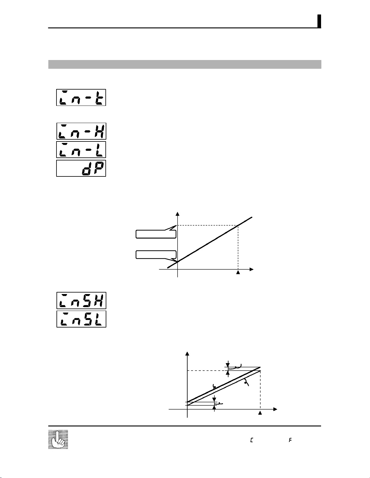
Ă• When the voltage input and current input are selected, scaling matched
to the control is required.
Ă• The scaling upper limit", scaling lower limit" and decimal point"
parameters (setup mode) are use for scaling.
Ă• The scaling upper limit" parameter sets the physical quantity to be
expressed by the upper limit value of input, and the scaling lower limit"
parameter sets the physical quantity to be expressed by the lower limit
value of input. The decimal point" parameter sets the number of digits
past the decimal point.
Ă• The following figure shows scaling example of 4 to 20 mA input. After
scaling, the humidity can be directly read. In this case, the decimal
point" parameter is set to 1".
Readout (humidity)
Scaling upper limit
value (95.0%)
Scaling lower limit
value (10.0%)
F Input shift
About the temperature unit
0
100%FS
Input (4 to 20 mA)
Ă• When temperature input is selected, scaling is not required. This is
because input is treated as the temperature" as it is matched to the
input type. However, note that the upper and lower limit values of the
sensor can be shifted. For example, if both the upper and lower limit valĆ
ues are shifted by 1.2_C, the process value (before shift) is regarded as
201.2_C after shift when input is 200_C before shift.
Ă• To set input shift, set shift values in the input shift upper limit" and
input shift lower limit" parameters (level 2 mode).
Temperature
Input shift upper limit value
Upper limit value
After shift
Before shift
Input shift lower
Lower limit value
0
To switch the temperature unit from _C" to _F" for temperature unit, switch the
setting of the _C/_F selection" parameter to [ăăăăăă] from [ăăăăăăă].
limit value
Input (%FS)
100
3–3
CHAPTER 3 BASIC OPERATION
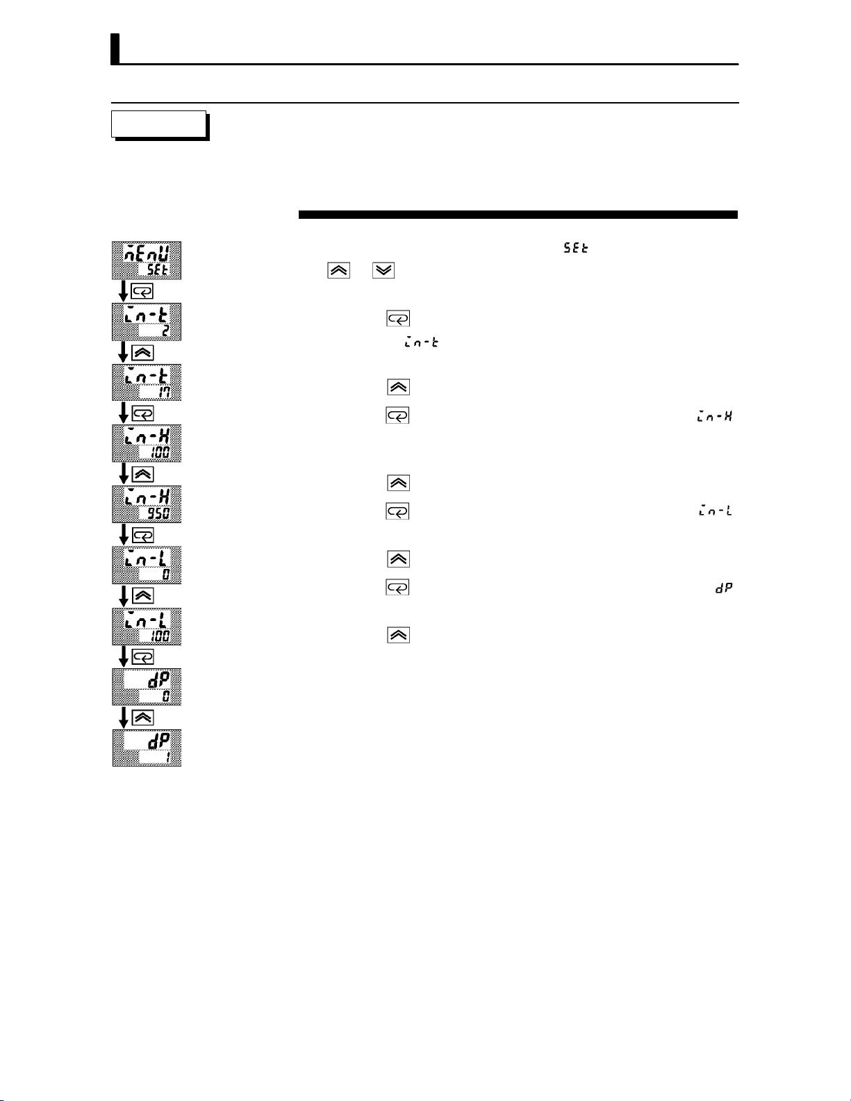
Setting Example
In this example, let's set the parameters as follows:
input type" = 17 (4 to 20 mA)"
scaling upper limit value" = 950"
scaling lower limit value" = 100"
decimal point" = 1"
(1) Select the menu display, and select [ăă ] (setup mode) using the
or keys. For details on selecting the menu display, see page
1Ć7.
(2) Press the
setup mode [
key to enter the setup mode. The top parameter in the
] input type" is displayed. The parameter default
is 2".
(3) Press the
(4) Press the
key until the display indicates 17".
key to fix the set value. The display changes to [ ]
(scaling upper limit value" parameter). The parameter default is
100".
(5) Press the
(6) Press the
key until the display indicates 950".
key to fix the set value. The display changes to [ ]
(“scaling lower limit value" parameter). The parameter default is 0".
(7) Press the
(8) Press the
key until the display indicates 100".
key to fix the set value. The display changes to [ĂĂĂĂĂ ]
(decimal point" parameter). The parameter default is 0".
(9) Press the
key until the display indicates 1".
3–4

3.3 Setting Output Specifications
Destinati
3.3 Setting Output Specifications
JOutput assign-
ments
Ă• Eight output are supported :
control output (heat)
control output (cool)
alarm outputs 1 to 3
LBA, and
error 1 (input error)
error 2 (A/D converter error).
These functions are assigned to control outputs 1 and 2, and auxiliary
output 1.
Ă• Restrictions on assignment destination are placed on some of the outĆ
puts. The following table shows where outputs may be assigned to.
Assignment
Output Function
Control output (heat) F F
Control output (cool) F F
Alarm 1 F F F
Alarm 2 F F F
Alarm 3 F F F
LBA F F F
Error 1; Input error F
Error 2; A/D converter error F
With control output (cool) the conditions for switching from standard
control to heating and cooling control are reached when the output
function is assigned at the cooling side during heating and cooling
control.
Control Output Auxiliary Output
on
1 2 1
JDirect/reverse
operation
In other words, heating and cooling control is carried out when control
output (cool) is assigned, and standard control is carried out when outĆ
put is not assigned. For details on heating and cooling control, see 4.1
Selecting the Control Method (page 4Ć2).
Ă• The same output function can not be assigned to a single destination
more than once.
Ă• Factory settings are as follows:
Control output (heat) = control output 1
Alarm 1 = control output 2
Alarm 2 = auxiliary output 1.
Ă• Output assignments are set in the control output 1 assignment", conĆ
trol output 2 assignment" and aux output 1 assignment" parameters
(setup mode).
Ă• Direct operation" (or normal operation) refers to control where the
manipulated variable is increased according to the increase in the proĆ
cess value. Alternatively, reverse operation" refers to control where the
manipulated variable is decreased according to the decrease in the proĆ
cess value.
For example, when the process value (PV), is lower than the set point
(SP), in a heating control system, the manipulated variable increases by
the difference between the PV and SP values.
Accordingly, this becomes reverse operation" in a heating control system.
Alternatively, this becomes direct operation" in a cooling control system.
Ă• Direct/reverse operation is set in the [
parameter (setup mode).
]direct/reverse operation"
3–5
CHAPTER 3 BASIC OPERATION
JControl period
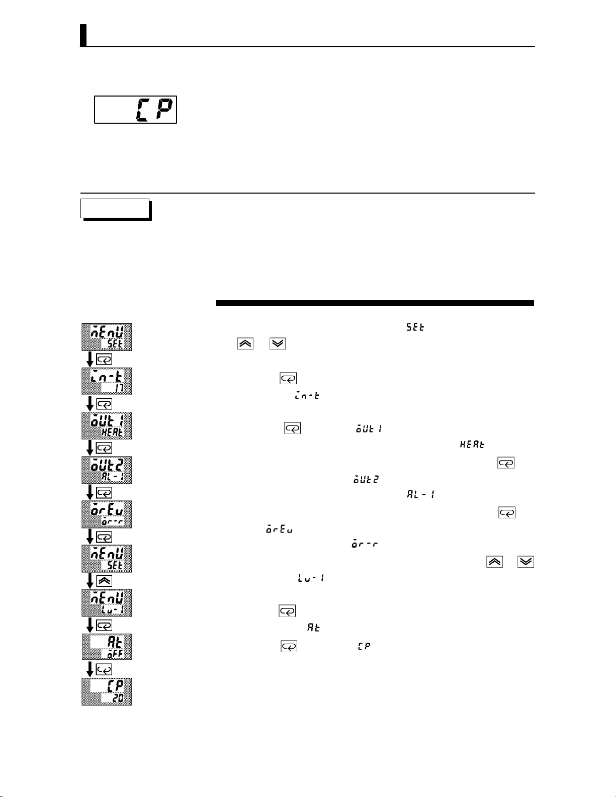
Setting Example
Ă• When the output unit is pulse output such as relay output, set the pulse
output cycle (control period). Though a shorter pulse period provides
better control performance, the control period should be set taking the
life expectancy of the output unit into consideration when the output
unit is relay.
Ă• The control period is set in the control period (heat)" parameter (level
1 mode). Factory setting is 20:20 seconds."
In this example, let's set the parameters as follows:
control output 1 assignment" = control output (heat)"
control output 2 assignment" = alarm output 1"
direct/reverse operation" = reverse operation"
control period" = 20 seconds"
All of the above settings in this example are factory settings. So, in this
example, we are only going to check the parameter settings.
(1) Select the menu display, and select [ĂĂĂ ] (setup mode) using the
or keys. For details on selecting the menu display, see page
1Ć7.
1 second min.
(2) Press the
setup mode [
key to enter the setup mode. The top parameter in the
] input type" is displayed. In this example, the
parameter setting is 17: 4 to 20 mA."
(3) Press the
parameter) is displayed. The parameter default is [
key until [ ] (control output 1 assignment"
].
(4) As the setting in this example is to be left as it is, press the
The display changes to [
parameter). The parameter default is [
] (control output 2 assignment"
].
(5) As the setting in this example is to be left as it is, press the
until [
The parameter default is [
] (direct/reverse operation" parameter) is displayed.
].
(6) As the setting in this example is to be left as it is, press the
keys to select [ ] (level 1 mode). For details on selecting the menu
display, see page 1Ć7.
(7) Press the
level 1 mode [ĂĂĂĂ
(8) Press the
key to enter the level 1 mode. The top parameter in the
] AT execute/cancel" is displayed.
key until [ĂĂĂĂ ] (control period" parameter) is disĆ
played. The parameter default is 20". As the setting in this example
is to be left as it is, quit key operation.
key.
key
or
3–6
3.4 Setting Alarm Type
Al
Ă• Three alarm outputs are supported: alarms 1 to 3. Of these, only the
alarm assigned as the output can be used.
Ă• Alarm output conditions are determined according to the combination
of the alarm type", alarm value" and alarm hysteresis" parameter
settings.
Ă• The contact conditions when alarm output is ON can be set to open"
or closed" in the close in alarm/open in alarm" parameter.
3.4 Setting Alarm Type
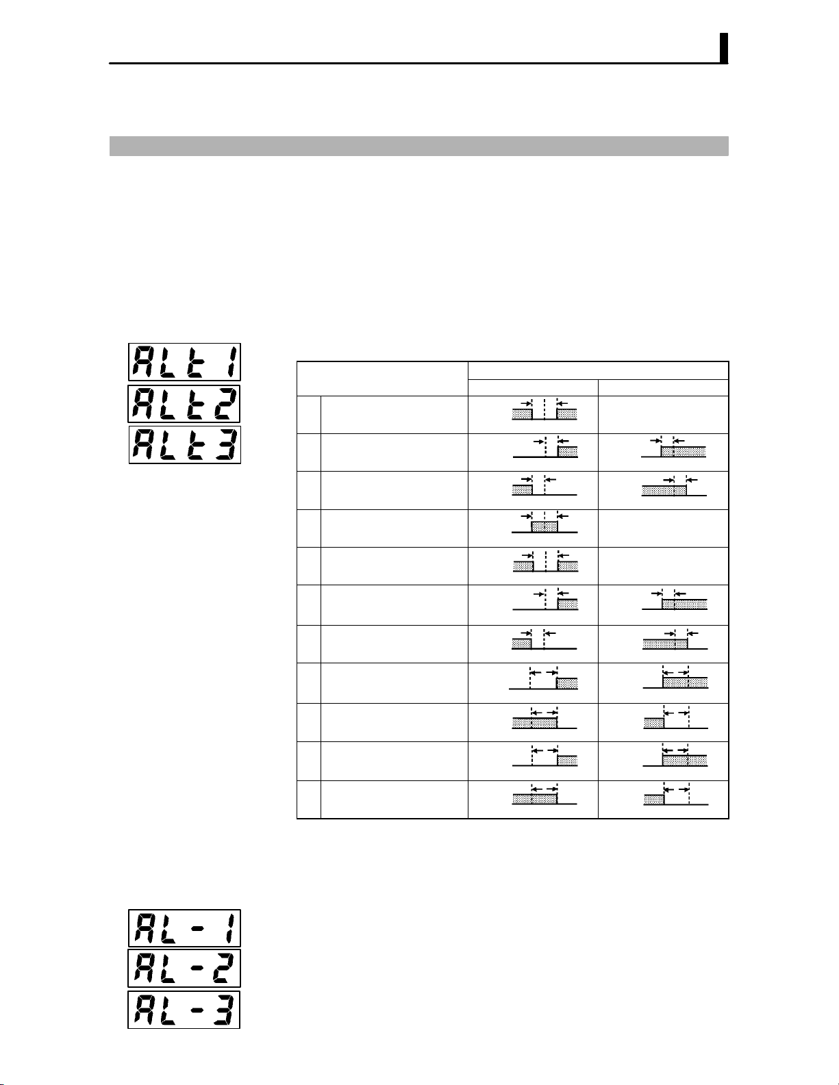
JAlarm type
Ă• The following table shows the alarm types supported by the E5CK conĆ
troller and their respective operations.
armType
Upper-and lower-limit alarm
1
(deviation)
Upper-limit alarm (deviation)
2
Lower-limit alarm (deviation)
3
Upper-and lower-limit range
4
alarm (deviation)
Upper-and lower-limit alarm
with standby sequence
5
(deviation)
Upper-limit alarm with
6
standby sequence (deviation)
Lower-limit alarm with
7
standby sequence (deviation)
Absolute-value upper-limit
8
alarm
Absolute-value lower-limit
9
alarm
Absolute-value upper-limit
10
alarm with standby sequence
Absolute-value lower-limit
11
alarm with standby sequence
When X is positive When X is negative
ON
OFF
ON
OFF
ON
OFF
ON
OFF
ON
OFF
ON
OFF
ON
OFF
ON
OFF
ON
OFF
ON
OFF
ON
OFF
Alarm Output Operation
XX
SP
X
SP
X
SP
XX
SP
XX
SP
X
SP
X
SP
X
0
X
0
X
0
X
0
Always ON
ON
OFF
ON
OFF
Always OFF
Always OFF
ON
OFF
ON
OFF
ON
OFF
ON
OFF
ON
OFF
ON
OFF
X
SP
X
SP
X
SP
X
SP
X
0
X
0
X
0
X
0
Ă• Alarm types are set independently for each alarm in the alarm 1 to 3"
parameters (setup mode). Factory setting is 2: UpperĆlimit alarm (deviĆ
ation)".
JAlarm value
Ă• Alarm values are indicated by X" in the table above. Alarm output
operation differs according to whether the value of the alarm is positive
or negative.
Ă• Alarm values are set independently for each alarm in the alarm value
1 to 3" parameters (level 1 mode). Factory setting is 0".
3–7

CHAPTER 3 BASIC OPERATION
Cl
O
JAlarm hysteresis
Ă• The hysteresis of alarm outputs when alarms are switched ON/OFF can
be set as follows.
Upper limit alarm Lower limit alarm
ON
OFF
Ă• Alarm hysteresis is set independently for each alarm in the alarm 1 to
3 hysteresis" parameters (level 2 mode). Factory setting is 0.02:
0.02%FS".
F Standby
sequence
Ă• “Standby sequence" is a function for unconditionally turning alarm outĆ
put OFF when the process value has left the alarm range once and it next
enters the alarm range.
Ă• For example, when the alarm type is set to “deviation lower limit," generĆ
ally the process value is within the alarm range, and alarm output
become ON as it is as the process value when the power is turned ON is
smaller than the set point. However, if the alarm type is set to deviation
lower limit with standby sequence", alarm output first becomes ON
when the process value exceeds the alarm setting value to leave the
alarm range and once again falls below the alarm value.
JClose in alarm/open in alarm
Ă• When the controller is set to “close in alarm," the status of the alarm outĆ
put function is output as it is. When set to “open in alarm," the status of
the alarm output function is output inverted.
osein alarm
penin alarm
Ă• Alarm type and close in alarm (normally open)/open in alarm (normally
close) can be set independently for each alarm.
Ă• Close in alarm/open in alarm is set in the alarm 1 to 3 open in alarm"
parameters (setup mode). Factory setting is [ĂĂ
Alarm hysteresis
Alarm value
Alarm hysteresis
ON
OFF
Alarm value
Alarm
ON ON Lit
OFF OFF Not lit
ON OFF Lit
OFF ON Not lit
Output Output LED
] close in alarm".
F Summary of
alarm operations
3–8
The figure below visually summarizes the above description of alarm
operations (when alarm type is set to lower limit alarm (deviation) with
standby sequence"):
Alarm type: lower limit alarm (deviation)
with standby sequence
PV
Alarm value
Alarm hysteresis
Time
Standby sequence
canceled
Alarm output
(close in alarm)
Close (ON)
Open (OFF)

3.4 Setting Alarm Type
Setting Example
When a set point for a humidity exceeds "10.0%, alarm1 will be output.
In this example, let's set the parameters as follows:
alarm type 1" = 1: (deviation upperĆand lowerĆlimit)"
alarm value 1" = 10.0"
alarm hysteresis" = 0.20"
close in alarm/open in alarm"=
: close in alarm"
Meanings of parameters, alarm histeresis" and open in alarm/close in
alarm" are the same settings at the shipment, so settings for operations
are omitted.
(1) Select the menu display, and select [ĂĂ
] (setup mode) using the
or keys. For details on selecting the menu display, see page 1Ć7.
(2) Press the
setup mode [
key to enter the setup mode. The top parameter in the
] input type" is displayed. In this example, the
parameter setting is 17: 4 to 20 mA".
(3) Press the
key until [ ] (alarm type 1" parameter) is disĆ
played. The parameter default is 2: deviation upper limit".
(4) Press the
key to return to 1: deviation upper and lower limit".
1 second min.
(5) Select the menu key, and select [
] (level 1 mode) using the
or keys. For details on selecting the menu display, see page 1Ć7.
(6) Press the
level 1 mode [ĂĂĂĂ
(7) Press the
key to enter the level 1 mode. The top parameter in the
] AT execute/cancel" is displayed.
key until [ ] (alarm value 1" parameter) is disĆ
played.
(8) In this example, the parameter setting is 0.0" so press the
until 10.0" is displayed.
key
About the Decimal
Point of the Alarm
Value
The decimal point of the alarm value conforms to the setting of the decimal point"
parameter (setup mode). In this example, the decimal point" parameter is set to
1". (During temperature input, the decimal point of the alarm value conforms to
the set sensor.)
3–9

CHAPTER 3 BASIC OPERATION
3.5 Protect Mode
JSecurity
JA/M key protect
Ă• This parameter allows you to protect until start of operation parameters
that do not change during operation to prevent unwanted modification.
Ă• The set value of the security" (protect) parameter specifies the range
of protected parameters.
Ă• When this parameter is set to 0", parameters are not protected.
Ă• When this parameter is set to 1" to 3", the number of modes that can
be displayed on the menu display is limited.
When set to 1", level 0 to 2, setup, expansion and option modes only can
be selected. When set to 2", only level 0 to 2 modes can be selected. When
set to 3", only level 0 and 1 modes can be selected.
Ă• When this parameter is set to 4" to 6", operations in only the level 0
mode can be selected, and the mode is not displayed on the menu display.
Ă• When this parameter is set to 5", only the PV/SP" parameter can be
used.
Ă• When this parameter is set to 6", only the PV/SP" parameter can be
used. (The set point can not change.)
Ă• Default is 1".
A/M
Ă• This parameter disables use of the
A/M
ple, if you protect use of the
key by the A/M key protect" parameter
key during operation. For examĆ
(protect mode) during auto operation, the controller cannot be set to the
manual mode, preventing manual operation of the controller during
operation.
Setting Example
A/M
A/M
• Let's protect the setup, expansion, option and calibration modes. Set the
parameters as follows:
security" = 2: Usable only in level 0 to 2 modes"
(1) Press for 1 second minium the
A/M
and keys simultaneously, the
controller enters the protect mode.
(2) In the protect mode, the top parameter in the protect mode security"
is displayed. The parameter default is 1". Press the
key to change
the parameter setting to 2".
A/M
(3) Press for 1 second minium the
and keys simultaneously, the
display changes to the PV/SP monitor" parameter (level 0 mode).
3–10
3.6 Starting and Stopping Operation
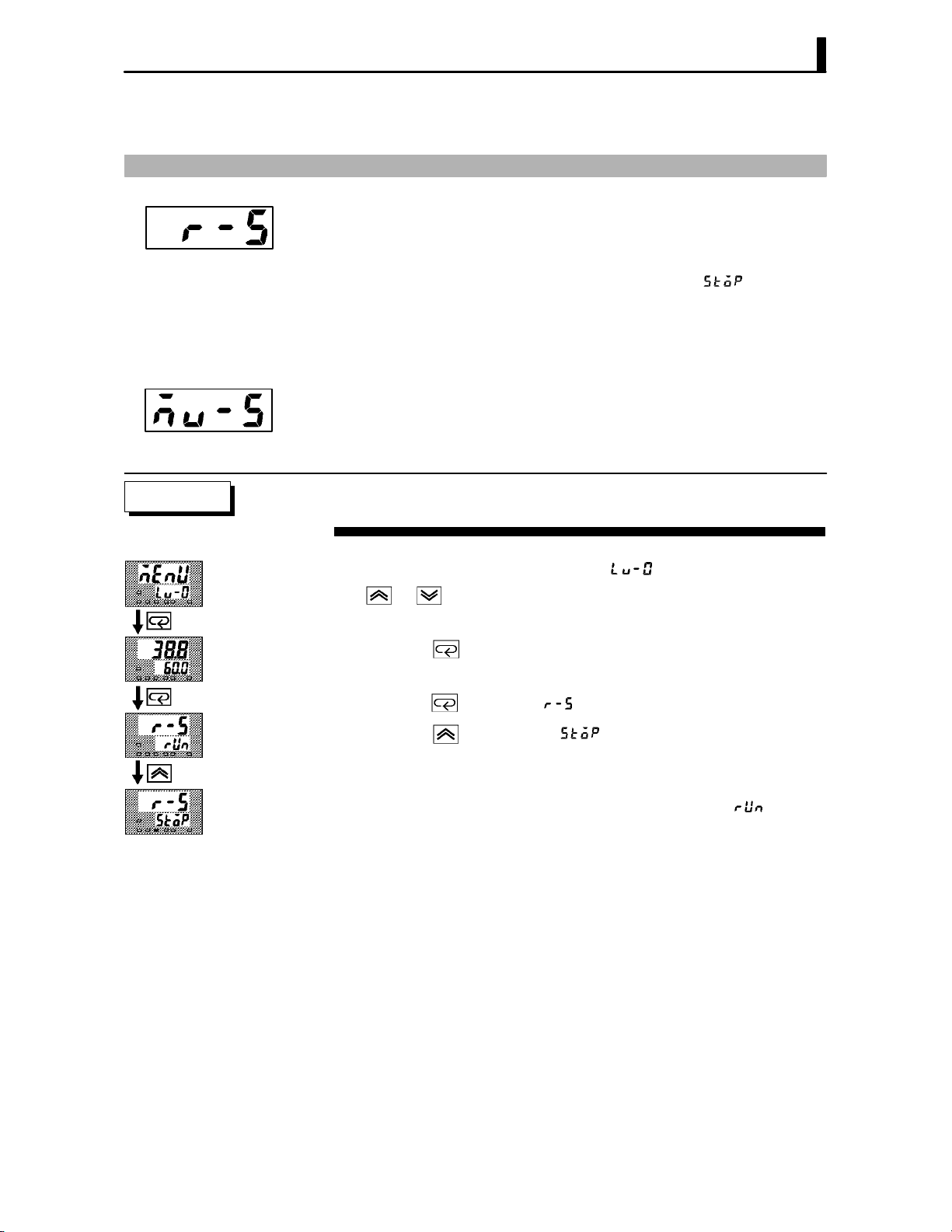
3.6 Starting and Stopping Operation
Ă• You can start and stop operation by changing the setting of the run/
stop" parameter (level 0 mode).
Ă• You can switch the RUN/STOP function up to 100,000 times.
Ă• To stop operation, set the run/stop" parameter to [Ă
stop state, the STOP" LED lights.
] (stop). In a
F Manipulated vari-
able at stop
Setting Example
Ă• To set output during a stop, specify the manipulated variable (Standard:
Ć5.0 to 105.0%, Heating and cooling: Ć105.0 to 105.0%) in the MV at
stop" parameter (level 2 mode). Factory setting is 0.0: 0.0%".
The following example describes the procedure to follow to stop control
during operation of the controller.
(1) Select the menu display, and select [ ] (level 0 mode) using the
or keys. For details on selecting the menu display, see page
1Ć7.
(2) Press the
played.
(3) Press the
(4) Press the
and operation stops.
key to enter the level 0 mode. The PV and SP are disĆ
key until [ĂĂĂ ] (run/stop" parameter) is displayed.
key to select [Ă ] (stop). The STOP" LED lights,
To resume operation, follow the above procedure to select [ĂĂĂ
The STOP" LED goes out and operation starts.
] (run").
3–11

CHAPTER 3 BASIC OPERATION
3.7 Adjusting Control Operation
JChanging the set
point
Setting Example
JManual operation
Ă• You can change the set point in the set point" parameter (level 0 mode).
Ă• However, note that you cannot change the set point when the security"
parameter (protect mode) is set to 6".
Ă• To change the set point, press the
value. If you leave the setting for two seconds, the set point is updated
to the new setting.
In the following example, let's change the humidity set point from 60%"
to 50%".
(1) Select the PV/SP monitor display.
(2) Press the
Ă• To set manual operation and manually set the manipulated variable,
press for 1 second minimum the
manual mode.
Ă• The manipulated variable is displayed on the No.2 display. To change the
manipulated variable, press the
manipulated variable is updated to the new setting.
Ă• Other modes cannot be selected while in the manual mode. To select
other modes, press for 1 second minimum the
is quit.
Ă• The automatic return of display function does not work while in the
manual mode.
Ă• When switching between manual and auto operation, the manipulated
variable is subject to balanceĆless, bumpĆless operation.
Ă• If the power is interrupted during manual operation, manual operation
is resumed at the manipulated variable at power interruption when the
power is reset.
Ă• You can switch the AUTO/MANUAL function up to 100,000 times.
key to change the setting to 50.0: 50.0%".
or keys to select the desired
A/M
key. The controller enters the
or keys. After two seconds, the
A/M
key. The manual mode
3–12
Balance-less,
Bump-less Operation
To prevent sudden changes in the manipulated variable when switching between
manual and auto operation, operation is resumed using the value that was active
immediately before operation was switched, and the value is brought gradually
closer to the value immediately after operation was switched.
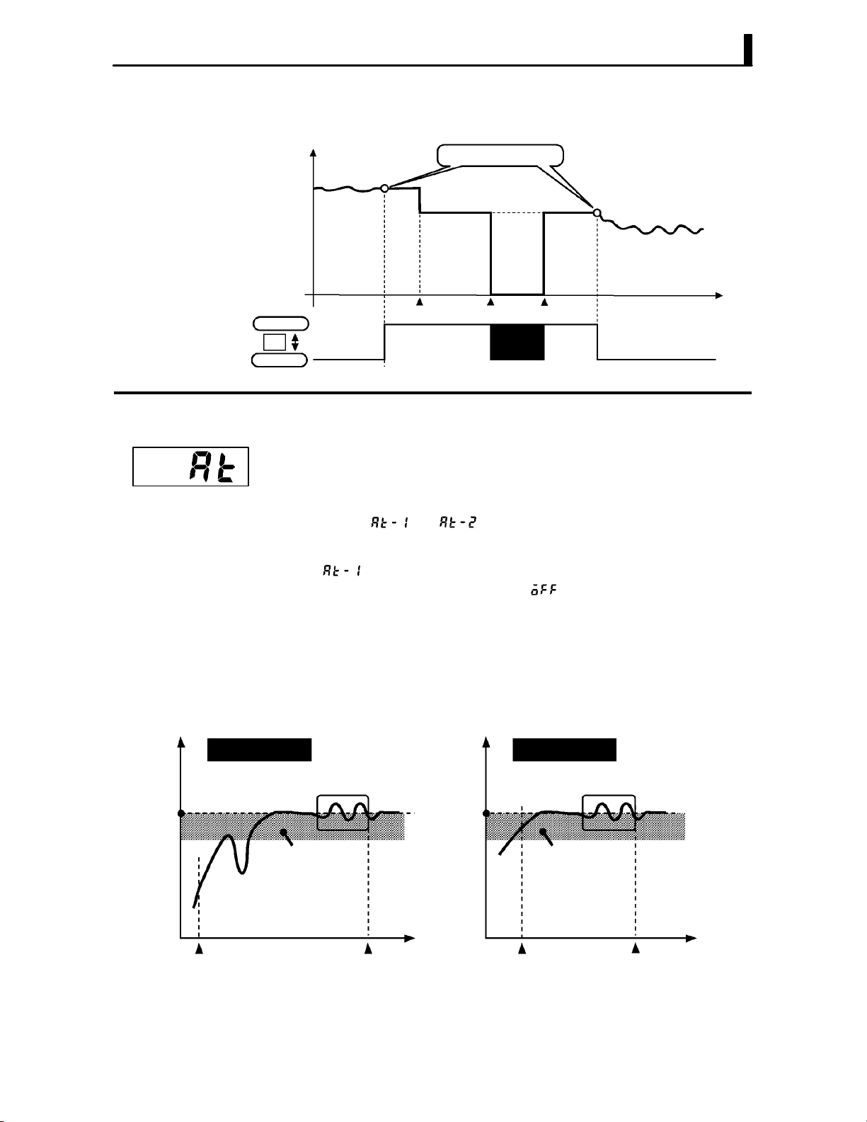
3.7 Adjusting Control Operation
The following diagram summarizes manual operation.
Manipulated variable (%)
Balance-less, bump-less points
JAuto-tuning
(A.T.)
F 40%AT
0
Manual
A/M
Auto
Manipulated variable
switched
OFF ON
Power interruption
Ă• AT (autoĆtuning) cannot be executed while operation is canceled or durĆ
ing ON/OFF control.
Ă• When you execute autoĆtuning, the optimum PID parameters are autoĆ
matically set by forcibly changing the manipulated variable to calculate
the characteristics (called the limit cycle method") of the control target.
During autoĆtuning, the AT LED flashes.
Ă• 40%AT or 100%AT can be selected by the limit cycle of MV change width.
Specify [
] or [ ], respectively, in the “AT execute/cancel" paĆ
rameter (level 1 mode).
Ă• During heating and cooling control, only 100%AT can be executed. (So,
[
Ă• To cancel AT execution, specify [ĂĂĂ
] (40%AT) will not be displayed.)
] (AT cancel").
In order to set the limit cycle of MV change width to 40%, select 40%AT
to execute autoĆtuning with fluctuations in the process value kept to a
minimum. However, note that autoĆtuning takes longer to execute
compared with 100%AT.
The timing by which limit cycles are generated varies according to whethĆ
er or not the deviation (DV) at the start of AT execution is 10% fullĆscale
or less.
Time
Deviation at start of AT
execution y 10% full-scale
Limit cycle of MV change
width 40%
Set point Set point
Deviation 10%
full-scale
Start of AT
execution
End of AT Start of AT
Time Time
Deviation at start of AT
execution < 10% full-scale
Deviation 10%
full-scale
execution
Limit cycle of MV change
width 40%
End of AT
3–13

CHAPTER 3 BASIC OPERATION
F 100%AT
Setting Example
In order to set the limit cycle of MV change width to 100%, select 100% AT
to shorten the AT execution time without worrying about fluctuations in
the process value.
Limit cycle of MV
change width 100%
Set point
Time
Start of AT
execution
End of AT
In this example, let's execute 40%AT.
AT execute
(1) Select [ ] (level 1 mode) using the or keys. For details on
selecting the menu display, see page 1Ć7.
(2) Press the
setup mode [ĂĂĂĂ
the parameter setting is [ĂĂĂ
(3) Press the
key to enter the level 1 mode. The top parameter in the
] AT execute/cancel" is displayed. In this example,
] AT cancel"
key to specify [ ].
(4) The AT LED flashes, and AT execution starts. When the AT LED goes
out (end of AT execution), the parameter automatically returns to
[ĂĂĂ
] (AT cancel").
Ă• In addition to AT, the E5CK is also provided with fuzzy selfĆtuning (ST)
that allows automatic calculation of the PID parameters suited to the
control target. However, note that the ST function operates only during
standard control by temperature input. For further information regardĆ
ing the ST, please see page 5Ć29 and AĆ10.
3–14
About PID Parameters
When control characteristics are already known, the PID parameters can be set
directly to adjust control.
PID parameters are set in the proportional band" (P), integrated time" (I) and
derivative time" (D) parameters (level 1 mode).
For details on the setting ranges of these parameters, see chapter 5 Level 1 Mode
(page 5Ć11).

CHAPTER4
CHAPTER 4
APPLIED OPERATION
This chapter describes each of the parameters required for making full
use of the features of the E5CK. Read this chapter while referring to the
parameter descriptions in chapter 5.
CHAPTER 4 APPLIED OPERATION
4.1 Selecting the Control Method 4-2. . . . . . . . . . . .
Heating and cooling control 4-2. . . . . . . . . . . . .
ON/OFF control 4-3. . . . . . . . . . . . . . . . . . . . . . .
4.2 Operating Condition Restrictions 4-4. . . . . . . .
Manipulated variable restrictions 4-4. . . . . . . .
Set point limiter 4-5. . . . . . . . . . . . . . . . . . . . . . .
SP ramp 4-5. . . . . . . . . . . . . . . . . . . . . . . . . . . . . .
4.3 How to Use Option Functions 4-7. . . . . . . . . . .
Event input 4-7. . . . . . . . . . . . . . . . . . . . . . . . . . .
Transfer output 4-8. . . . . . . . . . . . . . . . . . . . . . . .
4.4 LBA 4-9. . . . . . . . . . . . . . . . . . . . . . . . . . . . . . . . . .
4.5 Calibration 4-11. . . . . . . . . . . . . . . . . . . . . . . . . . . .
Calibrating thermocouple 4-12. . . . . . . . . . . . . . .
Calibrating platinum
resistance thermometer 4-15. . . . . . . . . . . . . . . . .
Calibrating current input 4-17. . . . . . . . . . . . . . .
Calibrating voltage input 4-18. . . . . . . . . . . . . . .
Checking indication accuracy 4-20. . . . . . . . . . . .
4–1

CHAPTER 4 APPLIED OPERATION
4.1 Selecting the Control Method
When selecting the control method, set the parameters according to the
following table. (Parameters are factoryĆset to heating control.)
Parameter
Control
Method
Heating control
(Standard)
Cooling control
(Standard)
Heating and cooling
control
For details on how to assign outputs, see 3.3 Setting Output Specifications
(page 3-5).
JHeating and
cooling control
F Dead band
Ă• When heating and cooling control is selected, the deadband" and coolĆ
ing coefficient" parameters can be used.
The dead band is set with the set point as its center. The dead band width
is the set value of the dead band" parameter (level 1 mode). Setting a posiĆ
tive value produces a dead band, while setting a negative value produces
an overlap band.
Output Output
Dead band: dead
band width = positive
Control output 1
assignment
Control output (heat)
Control output (heat)
Control output (heat) Control output (cool) Reverse operation
Control output 2
assignment
–
–
Overlap band: dead
band width = negative
Direct/Reverse
operations
Reverse operation
Direct operation
Heating
side
0
Set point Set point
F Cooling coeffi-
cient
F Manipulated vari-
able at stop
Switching with
Manual operation
Cooling
side
PV
Heating
side
0
Cooling
side
PV
If the heating and cooling characteristics of the control target greatly difĆ
fer, preventing satisfactory control characteristics from being obtained by
the same PID parameters, adjust the proportional band (P at cooling side)
using the cooling coefficient to balance control between the heating and
cooling sides. In heating and cooling control, P at the heating or cooling
side is calculated by the following formula:
Heating side P = P; Cooling side P = cooling coefficient P
Ă• In heating and cooling control, the manipulated variable output that is
output when controller operation is stopped is dependent on the set
value of the “MV at stop" parameter (level 2 mode) in the same way as
for standard control.
Ă• However, note that in heating and cooling control, the manipulated variĆ
able at the cooling side is treated as a negative value for the sake of conveĆ
nience. When the manipulated variable at STOP is a negative value, the
manipulated variable is output to only the cooling side, and when a posiĆ
tive value, the manipulated variable is output to only the heating side.
The factory setting is 0". If the controller is operated using the factory
setting, the manipulated variable is not output to both the heating and
cooling sides.
When the overlap band is set, the bumpless function that operates when switching
between manual and automatic operation may not work.
4–2

4.1 Selecting the Control Method
JON/OFF control
F Hysteresis
Ă• Switching between advanced PID control and ON/OFF control is carĆ
ried out by the PID / ON/OFF" parameter (expansion mode). When this
parameter is set to [ĂĂĂ
set to [
], ON/OFF control is selected. Default is [ĂĂĂ ].
], advanced PID control is selected, and when
Ă• In ON/OFF control, hysteresis is provided in the program when switchĆ
ing between ON and OFF to stabilize operation. The hysteresis width
provided during ON/OFF control is simply referred to as “hysteresis."
Control output (heat) and control output (cool) functions are set in the
“hysteresis (heat)" and “hysterisis (cool)" parameters, respectively.
Ă• In standard control (heating or cooling control), hysteresis can be set
only for the heating side.
Hysteresis (heat)
ON
OFF
Set point
PV
Ă• In heating and cooling control, a dead band can be set. So, 3Ćposition conĆ
trol is made possible.
Dead band
Parameters
Hysteresis (heat)
OFF
Symbol
Control output 1
Control output 2
Direct/Reverse
Dead band : Level 1 Heating and cooling control
Cooling coefficient : Level 1 Heating and cooling control
MV at stop : Level 2 Manipulated variable when control
Hysteresis (heat) : Level 1 ON/OFF control
Hysteresis (cool) : Level 1 ON/OFF control
PID / ON/OFF : Expansion ON/OFF control
Hysteresis (cool)
ON
Heating
side
Set point
Parameter Name: Mode Description
assignment : Setup
assignment : Setup
operation : Setup
Cooling side
For specifying control method
For specifying control method
For specifying control method
operation is stopped
PV
4–3

CHAPTER 4 APPLIED OPERATION
4.2 Operating Condition Restrictions
JManipulated vari-
able restrictions
F MV limiter
The upperĆand lowerĆlimit values of the manipulated variable can be
restricted by the MV limiter, and the change rate of the manipulated variĆ
able can be restricted by the MV change rate limiter.
The upperĆand lowerĆlimit values of the manipulated variable are set in
the MV upper limit" and MV lower limit" parameters (level 2 mode).
When the manipulated variable calculated by the E5CK is outside of the
range of the MV limiter, actual outputs are dependent on the set value of
these parameters.
Output (%)
100
0
MV upper limit value
MV lower
limit value
PV
In heating and cooling control, the manipulated variable at the cooling
side is treated as a negative value for the sake of convenience. The upper
limit is set for the heating side (positive value), and the lower limit is set
for the cooling side (negative value) as shown in the following figure.
F MV change rate
limiter
Output (%)
100
MV lower limit value
MV upper limit value
Heating
side
Set point
Cooling
side
PV
100
The MV change rate limit" parameter (level 2 mode) sets the maximum
permissible change width per second of the manipulated variable. If a
change in the manipulated variable exceeds this parameter setting, the
value calculated by the E5CK is reached while changing the value by the
perĆsecond value set in this parameter.
Output (%)
100
MV change rate
limit value
1 second
0
Switching point
Time
4–4

4.2 Operating Condition Restrictions
F Limiter operation
conditions
JSet point limiter
The limiters are invalid or cannot be set when any of the following condiĆ
tions occurs:
Ă• During ON/OFF control
Ă• During ST execution
Ă• During AT execution (only by MV change rate limiter)
Ă• During manual operation
Ă• When operation is stopped
Ă• When an error has occurred.
The setting range of the set point is limited by the set point limiter. The
upperĆand lowerĆlimit values of this set point limiter are set in the “Set
point upper limit" and “Set point lower limit" parameters (expansion
mode), respectively. However, note that when the set point limiter is reset,
the set point is forcibly changed to the upperĆor lowerĆlimit value of the set
point limiter if the set point is out of the limiter range. Also, when the inĆ
put type, temperature unit and scaling (sensor) range are changed, set
point limiter is forcibly reset to the scaling (sensor) range.
Scaling (sensor) range
Set point limiter
Setting range
Changed to upper
limit value
Changed to
the new upper limit
value
A
ĘB
SP
SP
JSP ramp
Input type changed
Set point Upper-and lower-limit values of the limiter
Scaling (sensor) upper-and lower-limit values
With the SP ramp function, the controller operates according to the value
(set point during SP ramp) limited by a change rate, instead of the changed
set point when set point is changed. The interval in which the set point
during SP ramp is limited is referred to as the “SP ramp".
SP
Set point
Switching point
SP ramp
SP ramp set
value
SP ramp time unit
Time
CB
Ę
4–5
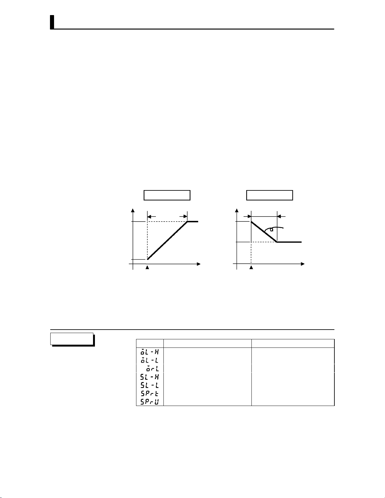
CHAPTER 4 APPLIED OPERATION
The change rate during the SP ramp is specified by the “SP ramp set value"
and “SP ramp time unit" parameters. At the “SP ramp set value" default
“0", the SP ramp function is disabled.
The set point changing in SP ramp can be monitored in the “Set point durĆ
ing SP ramp" parameter (level 0 mode).
F Operation at start
Set point
PV
F Restrictions dur-
ing SP ramp
The limiters are invalid or cannot be set when any of the following condiĆ
tions occurs:
If the SP ramp function is enabled when the power is turned ON, and when
“run" is switched to from “stop," process value may reach the set point afĆ
ter SP ramp in the same way as when the set point is changed. In this case,
operation is carried out with the process value regarded as the set point
before the change was made.
The direction of the SP ramp changes according to the relationship beĆ
tween the process value and the set point.
PV < SP PV > SP
SP
SP ramp
Set point
Time Time
Power ON
SP
SP ramp
PV
Same change
rate
Power ON
Ă• Execution of autoĆtuning starts after the end of SP ramp.
Ă• When the controller is switched to the manual mode, the set point
changes continuously until SP ramp ends.
Ă• When an error occurs, the SP ramp function becomes invalid.
Parameters
4–6
Symbol Parameter Name: Mode Description
MV upper limit : Level 2 Manipulated variable restrictions
MV lower limit : Level 2 Manipulated variable restrictions
MV change rate limit : Level 2 Manipulated variable restrictions
SP setting upper limit: Expansion SP setting restrictions
SP setting lower limit : Expansion SP setting restrictions
SP ramp set value : Level 2 SP changing restrictions
SP ramp time unit : Level 2 SP changing restrictions

4.3 How to Use Option Functions
Ă• For details on the communications function, refer to Chapter 6 Using
the Communications Function.
4.3 How to Use Option Functions
JEvent input
F Input assign-
ments
Multi-SP function
01
Run/Stop
Auto/Manual
F Run/Stop
Multi-SP
Ă• When using event input, add on the input unit (E53ĆCKB).
Ă• You can choose from the following three event input functions:
Run/Stop
Auto/Manual
MultiĆSP
Ă• When selecting an option function, first determine whether or not the
multiĆSP function is to be used. You can select two of the remaining
option functions only when the multiĆSP function is not in use.
Ă• When using the multiĆSP function, set the multiĆSP function" parameĆ
ter (option mode) to 1: ON". When using other functions, set this
parameter to 0: OFF".
Ă• When specifying event input other than the multiĆSP function, specify
event input in the event input assignmen 1" parameter (option mode).
The following table shows the relationship between parameter settings
and event input functions.
Setting Function
ON : Stop /OFF : Run
ON : Manual /OFF : Auto
Ă• When event input is set to ON", controller operation is stopped and the
STOP" LED lights. The content of event input is reflected in the “run/
stop" parameter (level 0 mode).
Ă• Run/Stop can be switched up to 100,000 times.
F Auto/Manual
About the event input and key operation
Ă• When event input is set to ON", the controller is switched for manual
operation, and the MANU" LED lights.
Ă• Turn event input ON/OFF while the controller is ON.
Ă• Auto/Manual can be switched up to 100,000 times.
There is no order of priority when inputting events and operating the keys. However,
because event input of run/stop or auto/manual must be carried out in either of the
physical ON/OFF states, parameters ultimately conform to event input even if an
attempt is made to switch the setting by key operation.
4–7

CHAPTER 4 APPLIED OPERATION
F Multi-SP
JTransfer output
Transfer output Transfer output
Ă• The set points set to the set point 0" and set point 1" parameters (level
1 mode) can be switched for use. However, note that these parameters
cannot be set when the multiĆSP function is not selected.
Ă• The set point can be switched up to 100,000 times.
Ă• When event input is OFF", set point 0 is used, and when ON" set point
1 is used.
Ă• When you have changed the set point, the set point of the currently
selected parameter is changed.
Ă• When you have switched between set point 0" and set point 1", the SP
ramp function works if the SP ramp function is enabled. The following
examples shows how the set point changes when you switch from set
point 0 and set point 1.
set point 1
set point 0
Event input
SP
OFF
SP
ramp
Time
ON
Ă• When using transfer output, add on the communications unit (E53ĆCKF).
Ă• You can select the following data items in the transfer output type"
parameter (option mode) as the transfer outputs:
Set point
Set poing during SP ramp
Process value
Manipulated variable (heat), and
Manipulated variable (cool).
Ă• These transfer outputs can be scaled according to the settings of the
transfer output upper limit" and transfer output lower limit" paramĆ
eters before output. Setting of an upper limit value smaller than the
lower limit value is allowed, so reverse scaling can also be carried out.
Also, the scale can be enlarged by the upperĆand lowerĆlimit width speciĆ
fied for each data item. The following example shows scaling of the readĆ
ing side manipulated variable.
(mA)
Reverse scaling Enlarged scale
(mA)
Parameters
4–8
20
4
Transfer output
upper limit: 0
Transfer
output lower
limit: 100
Manipulated
variable
(%)
20
4
0
Transfer
output lower
limit: 10
Transfer
output upper
limit: 80
100
Symbol Parameter Name: Mode Application
Multi-SP function : Option Event input functions
Event input assignment 1 : Option Event input functions
Set point 0 : Level 1 Multi-SP
Set point 1 : Level 1 Multi-SP
Transfer output type : Option Transfer output designation
Transfer output upper limit : Option Transfer output scaling
Transfer output lower limit : Option Transfer output scaling
Manipulated
variable (%)

4.4 LBA
4.4 LBA
Ă• The LBA (Loop Break Alarm) function can be used only when assigned
as an output. Also, the LBA function does not work when a memory
error or A/D converter error occurs.
Ă• LBA (Loop Break Alarm) is a function for judging that an error has
occurred somewhere on the control loop and outputting an alarm when
the process value does not change with the manipulated variable at a
maximum or minimum state. Accordingly, the LBA function can be used
as a means for detecting a malfunctioning control loop.
F LBA detection
time
F LBA detection
width
F LBA detection
example
Ă• Normally, when output is set to maximum or minimum, the process
value rises or falls after the dead time has elapsed. LBA is output if the
process value does not change in the predicted direction after a fixed
amount of time has elapsed. This fixed amount of time is the LBA detecĆ
tion time."
Ă• LBA operation sometimes becomes unstable when the process value
fluctuates considerably due to the control characteristics. The LBA
detection width is provided so that changes with respect to output can
be correctly detected. Changes smaller than the detection width due to
LBA detection timing are not regarded as changes.
Ă• The following example describes what happens when a heater burnout
at maximum output.
LBA detection time
PV
LBA detection time
LBA detection width
Output
Time
Heater burnout
Ă• LBA judgment is carried out at each LBA detection time from the point
of maximum output. In above figure, the process value (PV) is changing
greatly at the 1st judgment timing, so LBA remains OFF.
Ă• At the 2nd judgment timing, the process value increases as indicated by
the broken line of the process value is normal. This means that the
change width exceeds the LBA detection width, and LBA output remains
OFF.
Ă• If the heater burns out at the point shown in the above figure, the process
value decreases." Accordingly, it is judged that the process value is not
changing in the increasing direction" at the 2nd judgment timing and
the LBA output becomes ON.
LBA=ON
4–9
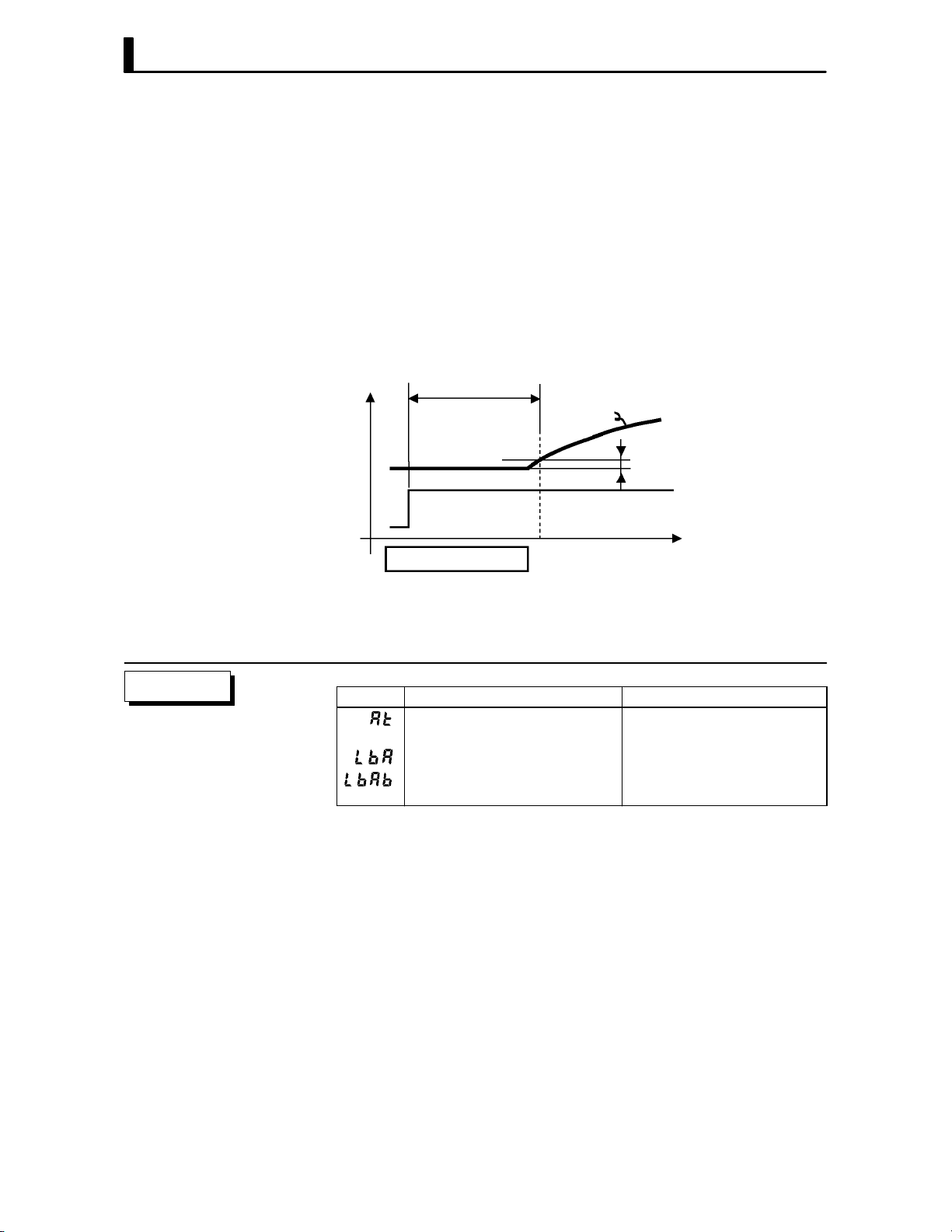
CHAPTER 4 APPLIED OPERATION
F Setting the LBA
detection time
F Determining the
LBA detection
time
Ă• The LBA detection time is automatically set by autoĆtuning (except in
heating and cooling control).
Ă• If the optimum LBA detection time cannot be obtained by autoĆtuning,
set the time in the “LBA detection time" parameter (level 2 mode).
Ă• Calculate the LBA detection time as follows:
(1) Set output to maximum.
(2) Measure the time it takes for the input change width to reach the LBA
detection width (default: 0.2 % fullĆscale).
(3) Take a value twice that of the measurement time as the LBA detection
time.
Measurement time Tm
PV
0.2%FS
Output
Time
LBA detection time = Tm x 2
Parameters
(4) In the case of ON/OFF operation, set the LBA detection time to a valĆ
ue longer than the control period.
Symbol Parameter Name: Mode Application
AT Execute/Cancel : Level 1 Automatic setting of LBA detec-
tion time
LBA detection time : Level 2 Setting of LBA detection time
LBA detection width : Expansion Changing of LBA detection
width
4–10

4.5 Calibration
Thermocouple
4.5 Calibration
Ă• To calibrate the E5CK controller, select [ĂĂ ] in the menu display to
select the calibration mode. [ĂĂ
Ă• However, note that [ĂĂ
] may not be displayed on the menu display
] is displayed.
when, for example, the user is calibrating the E5CK controller for the
first time. If this happens, [ĂĂ
] is displayed by changing the secuĆ
rity" parameter (protect mode) to 0".
Ă• The parameters in the calibration mode are configured as follows.
Platinum resistance
thermometer
Voltage inputCurrent input
Thermocouple 1
Transfer output
Data save
Thermocouple 2
Only when transfer
output function is
supported
Thermocouple 1 : K1/J1/L1/E/N/W/PLII
Thermocouple 2 : K2/J2/L2/R/S/B/T/U
Platinum resistance
thermometer
: JPt100/Pt100
Ă• To select the desired parameter, press the key. Parameters are disĆ
played in the following order:
Calibration of inputs → Calibration of transfer output →
Saving of calibration data
If the E5CK controller does not support the transfer output function,
calibration of transfer output is automatically deleted from the calibraĆ
tion procedure as follows:
Calibration of inputs → Saving of calibration data
Ă• Only inputs that have been set in the input type" parameter (setup
mode) can be calibrated. To temporarily save data for each of the calibraĆ
tion parameters, press the
key for 1 second.
Ă• Transfer output can be calibrated only when the communications unit
(E53ĆCKF)ĂisĂsetĂinĂtheĂcontroller.ăToăadjustĂdataĂitems,ĂpressĂthe
or keys.
Ă• The data save menu is displayed only when all calibration items have
temporarily been saved.
Ă• After calibrating input, you must always check indication accuracy. For
details, see page 4Ć20.
0 to 10V0 to 5V 1 to 5V
4–11

CHAPTER 4 APPLIED OPERATION
F Calibration item
menu
Calibration item
parameter
Process value
F Calibration save
mark
calibration save mark
JCalibrating ther-
mocouple
F Preparations
AC100-240V
(AC/DC24V )
Ă• Parameters are displayed on the No.1 display, and the process value is
displayed in Hexadecimal on the No.2 display.
Ă• Normally, the process value changes by several digits. The process value
flashes, for example, when a sensor error causes the process value to
stray from the calibration target range.
Ă• When the process value display is flashing, the process value is not saved
as data even if the
Ă• Once the E5CK controller has been calibrated by the user, [ĂĂĂ
key is pressed.
] is preĆ
ceded by the ." mark when the calibration mode is selected.
Ă• Calibrate according to the type of thermocouple, thermocouple 1 group
(K1, J1, L1, E, N, W, PLII) and thermocouple 2 group (K2, J2, L2, R, S,
B, T, U).
Ă• When calibrating, do not cover the bottom or top of the controller. Also,
do not touch the input terminals (Nos. 6 and 7) and compensating conĆ
ductor on the E5CK controller.
SOURCE
5
4
3
2
1
11 12
13 14
10
9
STV
8
7
6
Cold junction
compensator
0°C/32°F
Connecting the
Cold Junction Conductor
Compensating
DMM
conductor
Ă• Set the cold junction compensator to 0_C. However, make sure that
internal thermocouples are disabled (tips are open).
Ă• In the above figure, STV refers to a standard DC current/voltage source,
and DMM refers to a precision digital multimeter.
Ă• Use a compensating conductor selected thermocouple. However, note
that when thermocouple R, S, E, B, W or PLII is used, the compensating
conductor can be substituted with the cold junction compensator for
thermocouple K and compensating conductor.
Correct process values cannot be obtained if you touch the contact ends of the comĆ
pensating conductor during calibration of a thermocouple. Accordingly, short
(enable) or open (disable) the tip of the compensating conductor inside the cold juncĆ
tion compensator as shown in the figure below to create a contact or nonĆcontact
state for the cold junction compensator.
Cold junction
compensator
E5CK
controller
Compensating conductor Compensating conductor
0°C/32°F0°C/32°F
Short
E5CK
controller
Cold junction
compensator
Open
4–12
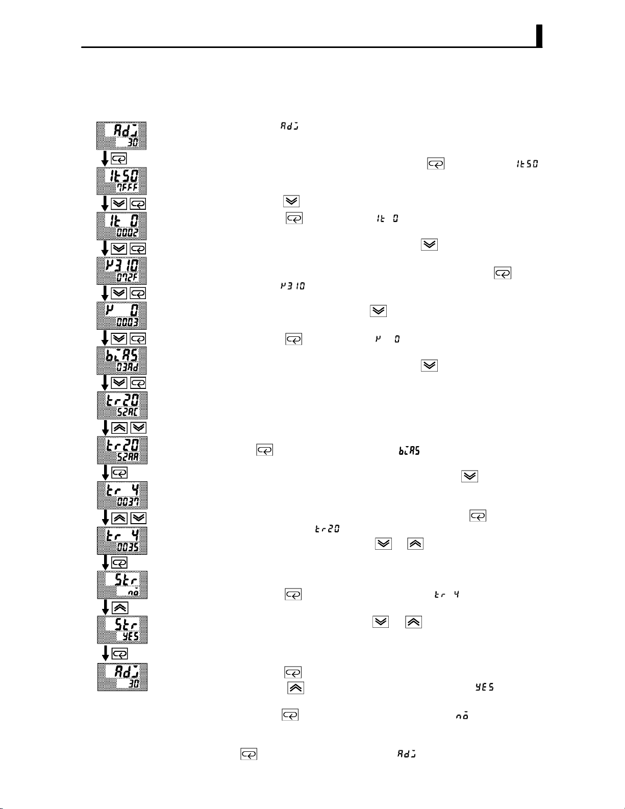
4.5 Calibration
F Calibration:
thermocouple 1
This example describes how to calibrate a thermocouple when the transfer
output function is supported. If the transfer output function is not supĆ
ported, skips steps (7) to (10).
(1) When [ĂĂĂ
No.2 display and counts down. This timer serves as a guide for the
aging time when aging is required.
(2) First, calibrate the main input. Press the
(50mV calibration display). Set STV output to 50mV. When the value
on the No.2 display has stabilized (changes of several digits max.),
press the
(3) Press the
STV output to 0mV. When the value on the No.2 display has stabilized
(changes of several digits max.), press the
the calibration data.
(4) Next, calibrate the cold junction compensator. Press the
display [
310mV. When the value on the No.2 display has stabilized (changes of
several digits max.), press the
tion data.
(5) Press the
STV output to 0mV. When the value on the No.2 display has stabilized
(changes of several digits max.), press the
the calibration data.
(6) Finally, calibrate the bias compensation value. Disconnect the STV,
and enable the thermocouple of the cold junction compensator. When
carrying this out, make sure that the wiring on the STV is disconĆ
nected.
Make sure that the cold junction compensator is set to 0_C and press
the
bias compensation value). When the value on the No.2 display has staĆ
bilized (changes of several digits max.), press the
rarily save the calibration data.
(7) Next, calibrate the transfer output function. If the transfer output
function is not supported, skip to step (11). Press the
play changes to [ ] (20mA calibration display).
(8) Set the output to 20mA by the
voltage on the digital multimeter. In the example on the left, the disĆ
play indicates that the value two digits smaller than before calibraĆ
tion is 20mA".
(9) Press the
display).
(10) Set the output to 4mA by the
voltage on the digital multimeter. In the example on the left, the disĆ
play indicates that the value two digits smaller than before calibraĆ
tion is 4mA".
(11) Press the
Press the
seconds later the calibration data is saved to internal memory. If you
press the
data is invalidated.
(12) This completes calibration of the thermocouple 1 group. Press the
key to return the display to [ĂĂĂ ].
] is displayed, the 30Ćminute timer is displayed on the
key to display [ ]
key to temporarily save the calibration data.
key to display [ ] (0mV calibration display). Set
key to temporarily save
key to
] (310mV calibration display). Set STV output to
key to temporarily save the calibraĆ
key to display [ ] (0mV calibration display). Set
key to temporarily save
key. The display changes to [ ] (calibration display for the
key to tempoĆ
key. The disĆ
or keys while monitoring the
key. The display changes to [ ] (4mA calibration
or keys while monitoring the
key until the display changes to the data save display.
key. The No.2 display changes to [ĂĂ ], and two
key when the No.2 display reads [ĂĂĂ ], the calibration
4–13

CHAPTER 4 APPLIED OPERATION
F Calibration:
thermocouple 2
This example describes how to calibrate a thermocouple when the transfer
output function is supported. If the transfer output function is not supĆ
ported, skips steps (7) to (10).
(1) When [ĂĂĂ
No.2 display and counts down. This timer serves as a guide for the
aging time when aging is required.
(2) First, calibrate the main input. Press the
(20mV calibration display). Set STV output to 20mV. When the value
on the No.2 display has stabilized (changes of several digits max.),
press the
(3) Press the
STV output to 0mV. When the value on the No.2 display has stabilized
(changes of several digits max.), press the
the calibration data.
(4) Next, calibrate the cold junction compensator. Press the
display [
310mV. When the value on the No.2 display has stabilized (changes of
several digits max.), press the
tion data.
(5) Press the
STV output to 0mV. When the value on the No.2 display has stabilized
(changes of several digits max.), press the
the calibration data.
(6) Finally, calibrate the bias compensation value. Disconnect the STV,
and enable the thermocouple of the cold junction compensator. When
carrying this out, make sure that the wiring on the STV is disconĆ
nected.
Make sure that the cold junction compensator is set to 0_C and press
the
the bias compensation value). When the value on the No.2 display has
stabilized (changes of several digits max.), press the
rarily save the calibration data.
(7) Next, calibrate the transfer output function. If the transfer output
function is not supported, skip to step (11). Press the
play changes to [ ] (20mA calibration display).
(8) Set the output to 20mA by the
voltage on the digital multimeter. In the example on the left, the disĆ
play indicates that the value two digits smaller than before calibraĆ
tion is 20mA".
(9) Press the
display).
(10) Set the output to 4mA by the
voltage on the digital multimeter. In the example on the left, the disĆ
play indicates that the value two digits smaller than before calibraĆ
tion is 4mA".
(11) Press the
Press the
seconds later the calibration data is saved to internal memory. If you
press the
data is invalidated.
(12) This completes calibration of the thermocouple 2 group. Press the
key to return the display to [ĂĂĂ ].
] is displayed, the 30Ćminute timer is displayed on the
key to display [ ]
key to temporarily save the calibration data.
key to display [ ] (0mV calibration display). Set
key to temporarily save
key to
] (310mV calibration display). Set STV output to
key to temporarily save the calibraĆ
key to display [ ] (0mV calibration display). Set
key to temporarily save
key. The display changes to [ ] (calibration display for
key to tempoĆ
key. The disĆ
or keys while monitoring the
key. The display changes to [ ] (4mA calibration
or keys while monitoring the
key until the display changes to the data save display.
key. The No.2 display changes to [ĂĂ ], and two
key when the No.2 display reads [ĂĂĂ ], the calibration
4–14

JCalibrating platinum resistance thermometer
F Preparation
AC100-240V
(AC/DC24V )
5
SOURCE
Ă• Use leads of the same thickness when connecting to the platinum resisĆ
tance thermometer.
Ă• In the above figure, 6Ćdial refers to a precision resistance box, and DMM
stands for a digital multimeter. However, note that the DMM is required
only when the transfer output function is supported.
Ă• Connect (short) the leads from terminal Nos. 6 and 7.
4
3
2
1
11 12
13 14
DMM
10
4.5 Calibration
9
8
7
6-dial
6
F Calibration
Short terminal
Nos.6 to 8
Change wiring.
Short terminal
Nos.6 to 8
Cont’d on next page
This example describes how to calibrate a platinum resistance thermomeĆ
ter when the transfer output function is supported. If the transfer output
function is not supported, skips steps (7) to (10).
(1) When [ĂĂĂ
No.2 display and counts down. This timer serves as a guide for the
aging time when aging is required.
(2) First, calibrate the main input. Press the
(300Ω calibration display). Set the 6Ćdial to 300Ω. When the value on
the No.2 display has stabilized (changes of several digits max.), press
the
(3) Press the
terminal No.6 to 8. When the value on the No.2 display has stabilized
(changes of several digits max.), press the
store the calibration data.
(4) Next, calibrate the BĆB' input. Change the wiring as follows.
] is displayed, the 30Ćminute timer is displayed on the
key to display [ ]
key to temporarily store the calibration data.
key to switch [ ] (0Ω calibration) display. Short
key to temporarily
10
9
8
7
6-dial
6
Make the connection across terminals 6 and 7 and the 6Ćdial as short
as possible. Short terminals 6 and 8.
(5) Press the
6Ćdial to 10Ω.. When the value on the No.2 display has stabilized
(changes of several digits max.), press the
store the calibration data.
(6) Press the
6Ćdial to 10Ω.. When the value on the No.2 display has stabilized
(changes of several digits max.), press the
store the calibration data.
key to display [ ] (10Ω calibration display). Set the
key to temporarily
key to display [ ] (0Ω calibration display). Set the
key to temporarily
4–15

CHAPTER 4 APPLIED OPERATION
From previous page
(7) Next, calibrate the transfer output function. If the transfer output
function is not supported, skip to step (11). Press the
play changes to [
(8) Set the output to 20mA by the
] (20mA calibration display).
or keys while monitoring the
key. The disĆ
voltage on the digital multimeter. In the example on the left, the disĆ
play indicates that the value two digits smaller than before calibraĆ
tion is 20mA".
(9) Press the
key. The display changes to [ ] (4mA calibration
display).
(10) Set the output to 4mA by the
or keys while monitoring the
voltage on the digital multimeter. In the example on the left, the disĆ
play indicates that the value two digits smaller than before calibraĆ
tion is 4mA".
(11) Press the
Press the
key until the display changes to the data save display.
key. The No.2 display changes to [ĂĂ ], and two
seconds later the calibration data is saved to internal memory. If you
press the
key when the No.2 display reads [ĂĂĂ ], the calibration
data is invalidated.
(12) This completes calibration of the platinum resistance thermometer.
Press the
key to return the display to [ĂĂĂ ].
4–16
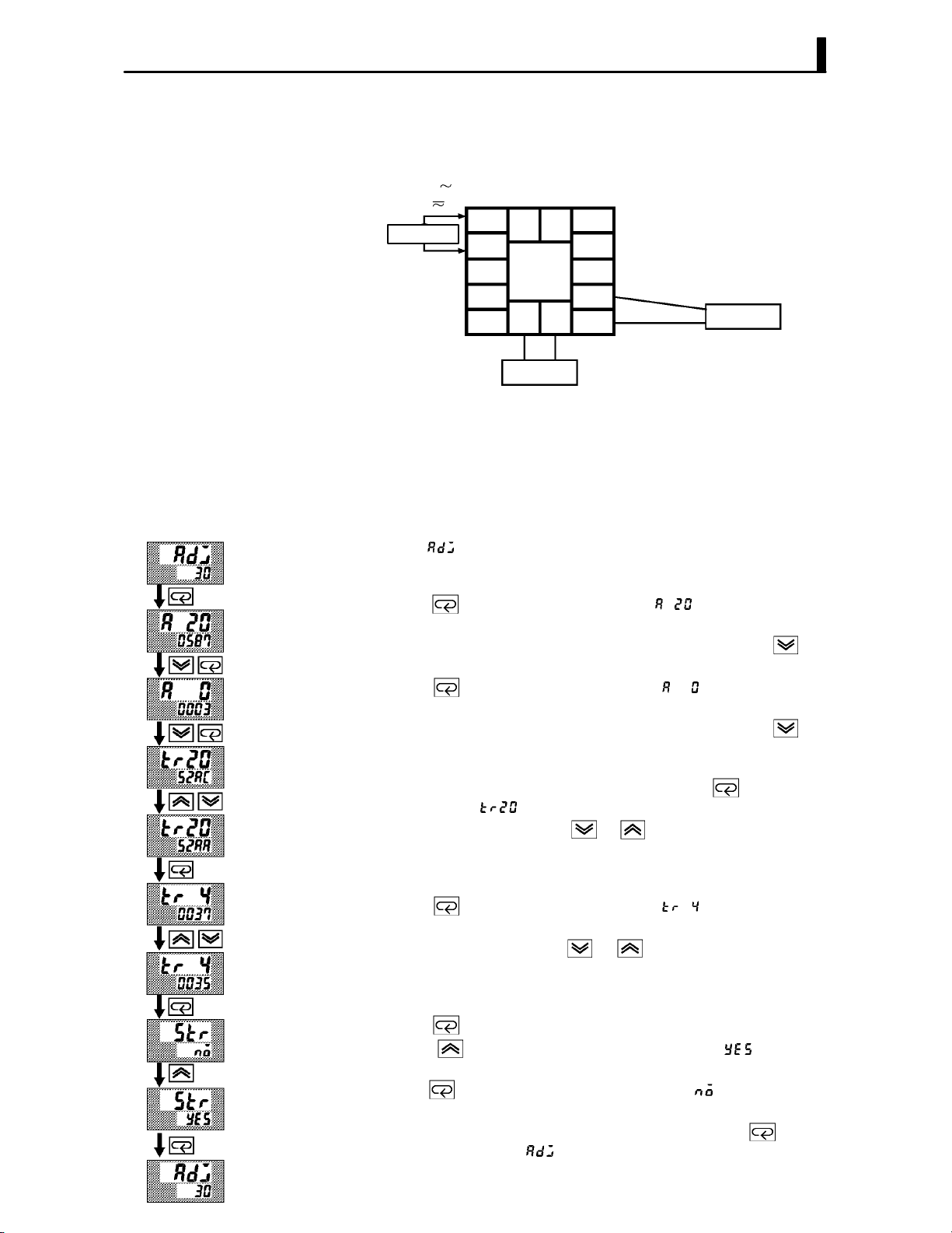
JCalibrating current input
F Preparation
AC100-240V
(AC/DC24V )
Ă• In the above figure, STV refers to a standard DC current/voltage source,
and DMM refers to a precision digital multimeter. However, note that
the DMM is required only when the transfer output function is supĆ
ported.
SOURCE
5
4
3
2
1
11 12
13 14
DMM
10
9
8
7
6
4.5 Calibration
STV
F Calibration
This example describes how to calibrate a current input when the transfer
output function is supported. If the transfer output function is not supĆ
ported, skips steps (4) to (7).
(1) When [ĂĂĂ
No.2 display and counts down. This timer serves as a guide for the
aging time when aging is required.
(2) Press the
display). Set the STV output to 20mA. When the value on the No.2 disĆ
play has stabilized (changes of several digits max.), press the
to temporarily store the calibration data.
(3) Press the
display). Set the STV output to 0 mA. When the value on the No.2 disĆ
play has stabilized (changes of several digits max.), press the
to temporarily store the calibration data.
(4) Next, calibrate the transfer output function. If the transfer output
function is not supported, skip to step (8). Press the
play changes to [
(5) Set the output to 20mA by the
voltage on the digital multimeter. In the example on the left, the disĆ
play indicates that the value two digits smaller than before calibraĆ
tion is 20mA".
(6) Press the
display).
(7) Set the output to 4mA by the
voltage on the digital multimeter. In the example on the left, the disĆ
play indicates that the value two digits smaller than before calibraĆ
tion is 4mA".
(8) Press the
Press the
seconds later the calibration data is saved to internal memory. If you
press the
data is invalidated.
(9) This completes calibration of current input. Press the
return the display to [ĂĂĂ ].
] is displayed, the 30Ćminute timer is displayed on the
key. The display changes to [ ] (20mA calibration
key
key. The display changes to [ ] (0mA calibration
key
key. The disĆ
] (20mA calibration display).
or keys while monitoring the
key. The display changes to [ ] (4mA calibration
or keys while monitoring the
key until the display changes to the data save display.
key. The No.2 display changes to [ĂĂ ], and two
key when the No.2 display reads [ĂĂĂ ], the calibration
key to
4–17

CHAPTER 4 APPLIED OPERATION
JCalibrating voltage input
F Preparation
AC100-240V
(AC/DC24V )
Ă• In the above figure, STV refers to a standard DC current/voltage source,
and DMM refers to a precision digital multimeter. However, note that
the DMM is required only when the transfer output function is supĆ
ported.
SOURCE
5
4
3
2
1
11 12
13 14
DMM
10
9
8
7
6
STV
F Calibration:
0 to 5 V, 1 to 5 V
This example describes how to calibrate voltage input when the transfer
output function is supported. If the transfer output function is not supĆ
ported, skips steps (4) to (7).
(1) When [ĂĂ
No.2 display and counts down. This timer serves as a guide for the
aging time when aging is required.
(2) Press the
play). Set the STV output to 5V. When the value on the No.2 display
has stabilized (changes of several digits max.), press the
temporarily store the calibration data.
(3) Press the
play). Set the STV output to 0V. When the value on the No.2 display
has stabilized (changes of several digits max.), press the
temporarily store the calibration data.
(4) Next, calibrate the transfer output function. If the transfer output
function is not supported, skip to step (8). Press the
play changes to [
(5) Set the output to 20mA by the
voltage on the digital multimeter. In the example on the left, the disĆ
play indicates that the value two digits smaller than before calibraĆ
tion is 20mA".
(6) Press the
display).
(7) Set the output to 4mA by the
voltage on the digital multimeter. In the example on the left, the disĆ
play indicates that the value two digits smaller than before calibraĆ
tion is 4mA".
(8) Press the
Press the
seconds later the calibration data is saved to internal memory. If you
press the
data is invalidated.
(9) This completes calibration of voltage input (0 to 5V, 1 to 5V). Press the
key to return the display to [ĂĂ ].
] is displayed, the 30Ćminute timer is displayed on the
key. The display changes to [ ] (5 V calibration disĆ
key to
key. The display changes to [ ] (0V calibration disĆ
key to
key. The disĆ
] (20mA calibration display).
or keys while monitoring the
key. The display changes to [ ] (4mA calibration
or keys while monitoring the
key until the display changes to the data save display.
key. The No.2 display changes to [ĂĂ ], and two
key when the No.2 display reads [ĂĂĂ ], the calibration
4–18

4.5 Calibration
F Calibration :
0 to 10V
This example describes how to calibrate voltage input when the transfer
output function is supported. If the transfer output function is not supĆ
ported, skips steps (4) to (7).
(1) When [ĂĂ
No.2 display and counts down. This timer serves as a guide for the
aging time when aging is required.
(2) Press the
display). Set the STV output to 10V. When the value on the No.2 disĆ
play has stabilized (changes of several digits max.), press the
to temporarily store the calibration data.
(3) Press the
play). Set the STV output to 0V. When the value on the No.2 display
has stabilized (changes of several digits max.), press the
temporarily store the calibration data.
(4) Next, calibrate the transfer output function. If the transfer output
function is not supported, skip to step (8). Press the
play changes to [
(5) Set the output to 20mA by the
voltage on the digital multimeter. In the example on the left, the disĆ
play indicates that the value two digits smaller than before calibraĆ
tion is 20mA".
(6) Press the
display).
(7) Set the output to 4mA by the
voltage on the digital multimeter. In the example on the left, the disĆ
play indicates that the value two digits smaller than before calibraĆ
tion is 4mA".
(8) Press the
Press the
seconds later the calibration data is saved to internal memory. If you
press the
data is invalidated.
(9) This completes calibration of voltage input (0 to 10V). Press the
key to return the display to [ĂĂ ].
] is displayed, the 30Ćminute timer is displayed on the
key. The display changes to [ ] (10V calibration
key
key. The display changes to [ ] (0V calibration disĆ
key to
key. The disĆ
] (20mA calibration display).
or keys while monitoring the
key. The display changes to [ ] (4mA calibration
or keys while monitoring the
key until the display changes to the data save display.
key. The No.2 display changes to [ĂĂ ], and two
key when the No.2 display reads [ĂĂĂ ], the calibration
4–19
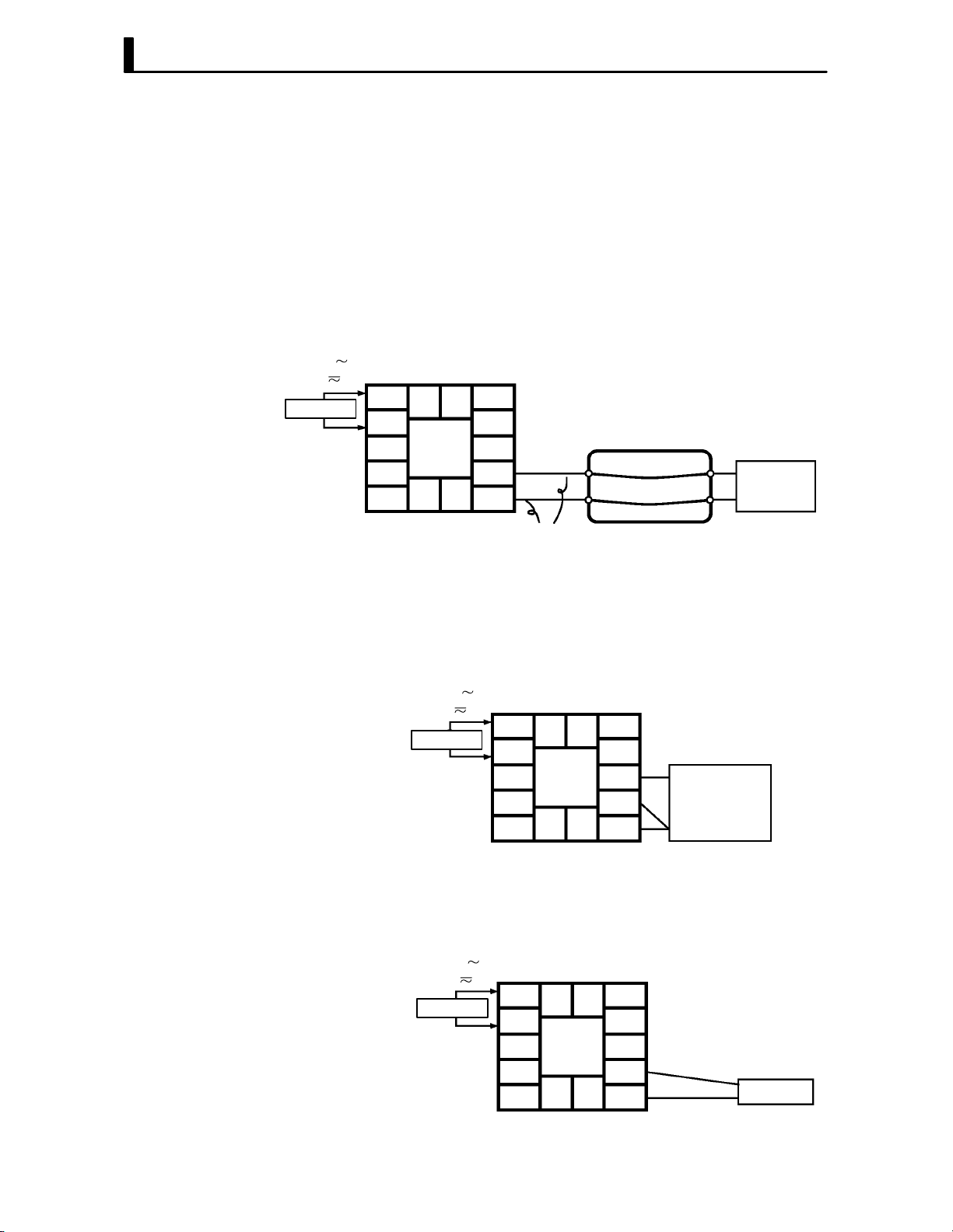
CHAPTER 4 APPLIED OPERATION
JChecking indica-
tion accuracy
F Thermocouple
AC100-240V
(AC/DC24V )
SOURCE
Ă• After calibrating input, make sure that you check indication accuracy to
make sure that the E5CK controller has been correctly calibrated.
Ă• Operate the E5CK controller in the PV/SP monitor (level 0 mode) mode.
Ă• Check the indication accuracy at the upper and lower limits and midĆ
point.
Ă• Preparation
The following figure shows the required device connection. Make sure
that the E5CK controller and cold junction compensator are connected
by a compensating conductor for the input type that is to be used during
actual operation.
5
11 12
4
3
2
13 14
1
Ă• Operation
Make sure that the cold junction compensator is at 0_C, and set STV outĆ
put to the voltage equivalent to the starting power of the check value.
10
9
8
7
6
Compensating
conductor
Cold junction
compensator
STV
F Platinum resis-
tance thermometer
F Current or volt-
age input
Ă• Preparation
The following figure shows the required device connection.
AC100-240V
(AC/DC24V )
5
SOURCE
11 12
4
3
2
13 14
1
Ă• Operation
Set the 6Ćdial to the resistance equivalent to the check value.
Ă• Preparation
The following figure shows the required device connection.
10
9
8
7
6
6-dial
AC100-240V
(AC/DC24V )
SOURCE
5
4
3
2
1
11 12
13 14
10
9
8
7
6
STV
4–20
Ă• Operation
Set the STV to the current or voltage value equivalent to the check value.

CHAPTER5
CHAPTER 5
PARAMETERS
This chapter describes the parameters of the E5CK. Use this chapter as
a reference guide.
CHAPTER 5 PARAMETERS
Conventions Used in this Chapter 5Ć2. . . . . . . . . . . .
Protect Mode 5Ć3. . . . . . . . . . . . . . . . . . . . . . . . . . . . . . .
Manual Mode 5Ć5. . . . . . . . . . . . . . . . . . . . . . . . . . . . . .
Level 0 Mode 5Ć6. . . . . . . . . . . . . . . . . . . . . . . . . . . . . . .
Level 1 Mode 5Ć9. . . . . . . . . . . . . . . . . . . . . . . . . . . . . . .
Level 2 Mode 5Ć15. . . . . . . . . . . . . . . . . . . . . . . . . . . . . . .
Setup Mode 5Ć21. . . . . . . . . . . . . . . . . . . . . . . . . . . . . . . .
Expansion Mode 5Ć27. . . . . . . . . . . . . . . . . . . . . . . . . . . .
Option Mode 5Ć32. . . . . . . . . . . . . . . . . . . . . . . . . . . . . . .
Calibration Mode 5Ć36. . . . . . . . . . . . . . . . . . . . . . . . . . .
5–1
CHAPTER 5 PARAMETERS
Conventions Used in this Chapter
JThe meaning of icons used in this chapter
Describes the functions of the parameter.
Function
Describes the range and defaults of the parameter setting.
Comment
Used for monitorĆdedicated parameters.
Describes the range of the monitor values.
Monitor
Describes a procedure using parameters in operating instructions.
Example
of use
Describes related parameters and items.
See
Describes models of the E5CK or option units supporting the parameter being
described.
Model
JAbout parameter display
On the E5CK controller, only parameters that can be used are displayed. These parameters are
displayed only when the Conditions of Use" on the right of the parameter heading are satisfied.
However, note that the settings of protected parameters are still valid, and are not displayed
regardless of the conditions of use.
AT Execute/cancel
Conditions of Use
The controller must
be in operation.
5–2

Mod
Protect Mode
Ă• The protect mode is for disabling (protecting) the functions of the menu key or
A/M
key. Before changing parameters in this mode, first make sure that protecting the
menu key or
Ă• To select this mode, press the
mum. To exit this mode, press the
A/M
key will not cause any problems in operation.
A/M
key and key simultaneously for 1 second miniĆ
A/M
key and key down again simultaneously
for 1 second minimum.
Ă• The following table shows the parameters supported in this mode and the page where
the parameter is described.
Symbol
Parameter Name Page
Security 5-3
[A/M] key protect 5-4
Security
Ă• This parameter specifies which parameters are protected. However, note that the
protect mode and manual mode cannot be protected.
Function
Comment
Ă• When this parameter is set to 0" to 3", only the modes indicated by the f" mark
in the table below can be selected on the menu display. For example, when this paramĆ
eter is set to 2", only level 0 to 2 modes can be selected.
e
Calibration f
Option f f
Expansion f f
Setup f f
Level 2 f f f
Level 1 f f f f
Level 0 f f f f f f ∗
0 1 2 3 4 5 6
Set value
Ă• When this parameter is set to 4" to 6", operations in only the level 0 mode can be
selected, and the mode is not displayed on the menu display.
Ă• When this parameter is set to 5", only the PV/SP" parameter in the level 0 mode
can be used.
Ă• When this parameter is set to 6", only the PV/SP" parameter in the level 0 mode
can be used. (The set point cannot change.)
Ă• Default is 1". (Only the calibration mode is protected.)
FĂRelated article
3.5 Protect Mode (page 3Ć10)
See
5–3
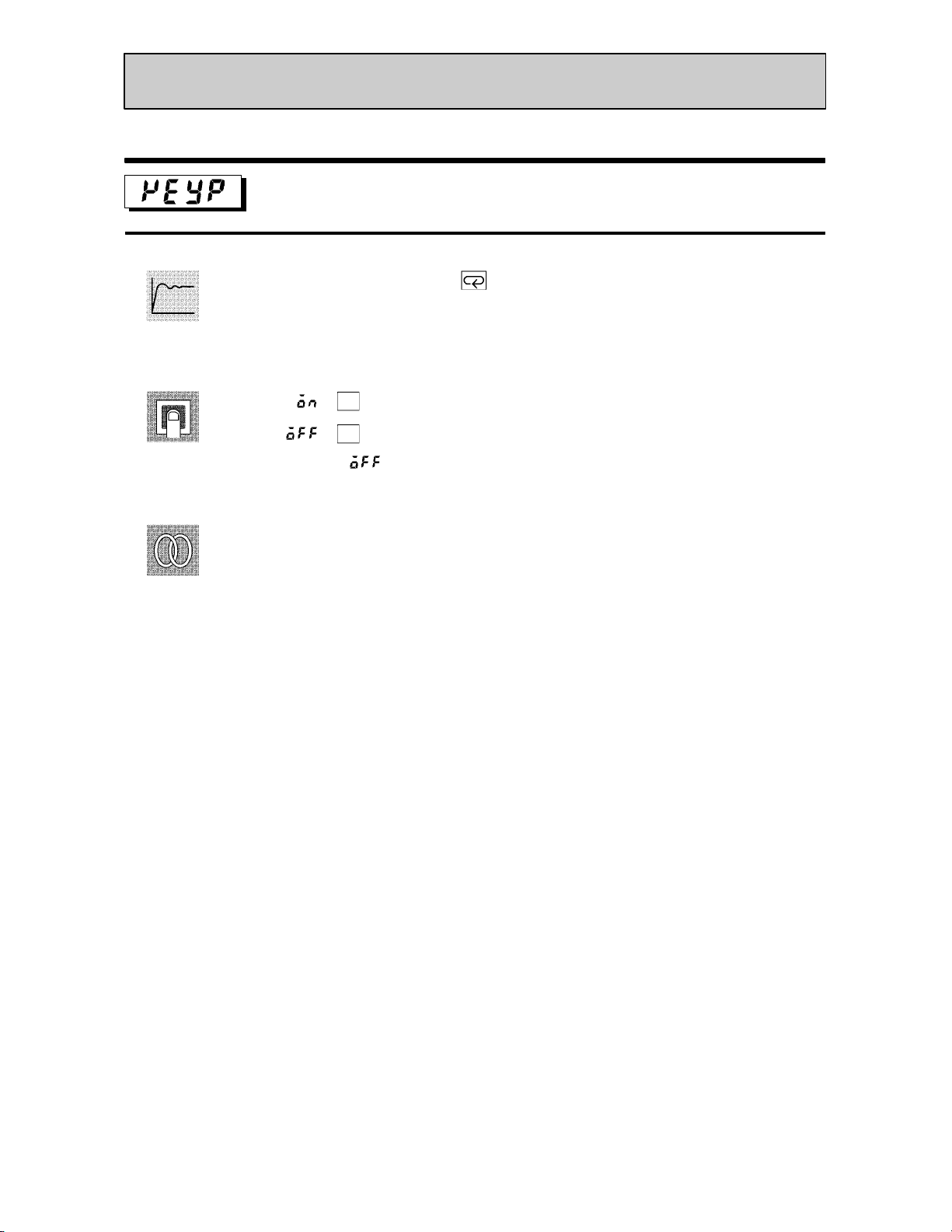
CHAPTER 5 PARAMETERS
Protect Mode
[A/M] key protect
Ă• Invalidate the function of the key. In other words, you cannot switch between the
auto and manual operations by key operation.
Function
Ă• [Ă ĂĂĂ
Ă• [
Comment
Ă• Default = [
]:
]:
A/M
key protect ON
A/M
key protect canceled
]
See
FĂRelated article
3.5 Protect Mode (page 3Ć10)
5–4
Function
Manual Mode
Ă• In this mode, manual operations are possible, and the MANU" LED lights.
Ă• When this mode is selected, the manipulated variable that was active immediately
before the mode was switched to is output. When changing the manipulated variable,
change it using the
autoĆtuning is canceled.
Ă• To select this mode when in the level 0 to 2 modes, press the
mum. To exit this mode, press the
to the level 0 mode.
Ă• Manual MV" is the only parameter available in this mode.
Manual MV
Ă• Set the manipulated variable for manual operation.
Ă• The process value is displayed on the No.1 display, and the manipulated variable is
displayed on the No.2 display. Change the manipulated variable using the
keys.
or keys. When this mode is selected during autoĆtuning,
A/M
key for 1 second miniĆ
A/M
key for 1 second minimum. The mode changes
or
Comment
See
Process value
Manipulated variable
[MANU] LED
The manual manipulated variable is held when the power is interrupted.
Control Method Setting Range
Standard -5.0 to 105.0 % 0
Heating and cooling -105.0 to 105.0 % 0
Unit Default
FĂRelated article
3.7 Adjusting Control Operation (page 3Ć12)
5–5

CHAPTER 5 PARAMETERS
Level 0 Mode
Ă• The parameters in this mode can be used only when the security" parameter (proĆ
tect mode) is set to 0" to 4".
Ă• The PV/SP" parameter can also be used when the Security" parameter is set to 5"
or 6". However, note that when set to 6", the SP cannot be changed.
Ă• This mode is used for monitoring the process value, set point and manipulated variĆ
able during operation, and for checking and setting the SP setting value. It is also
used for starting and stopping controller operation.
Ă• To select this mode when in the levels 1 and 2, setup, expansion, option and calibraĆ
tion modes, press the
menu display. If you select [
controller enters the level 0 mode.
Ă• To select parameters in this mode, press the
use the
Ă• The following table shows the parameters supported in this mode and the page where
the parameter is described.
Symbol Parameter Name
key for 1 second minimum. The display changes to the
] then press key for 1 second minimum, the
key. To change parameter settings,
or keys.
Page
PV/SP 5-6
Set point during SP ramp 5-7
MV monitor (heat) 5-7
MV monitor (cool) 5-7
Run/Stop 5-8
Function
Comment
See
PV/SP
Process value
Set point
Ă• The process value is displayed on the No.1 display, and the set point is displayed on
the No.2 display. The set point can be set.
Ă• When the multiĆSP function is in use, the value of whichever is set, set point 0 or 1,
is linked.
Ă• The decimal point position is dependent on the selected sensor during temperature
input and on the results of scaling during analog input.
Ă• Process value
Monitor Range
Scaling lower limit -10%FS to scaling upper limit +10%FS
During temperature input, the range of the currently selected sensor is taken as the
monitor range.
Ă• Set point
Setting Range
SP setting lower limit to SP setting upper limit EU 0
FĂRelated article
3.7 Adjusting Control Operation (page 3Ć12)
FĂRelated parameters
Input type" Scaling upper limit" Scaling lower limit" Decimal point" (setup mode)
SP setting upper limit" SP setting lower limit" (expansion mode)
Unit
EU
Unit Default
5–6

Level 0 Mode
Function
Monitor
See
Set point during SP ramp
Conditions of Use
The SP ramp function must be enabled.
Ă• Sets the set point.
Moniter Range
SP setting lower limit to SP setting upper limit EU 0
Unit Default
FĂRelated article
3.7 Adjusting Control Operation (page 3-12)
FĂRelated parameters
PV/SP" (level 0 mode)
SP ramp time unit" SP ramp set value" (level 2 mode)
Set point upper limit" Set point lower limit (expansion mode)
MV monitor (heat)
Function
Monitor
MV monitor (cool)
Ă• This parameter cannot be set.
Ă• Monitors the manipulated variable on the heating or cooling side.
Ă• The manipulated variable in a standard control system is checked in the MV moniĆ
tor (heat)" parameter.
Ă• The MV monitor (cool)" parameter can be used only during heating and cooling conĆ
trol.
Ă• MV monitor (heat)
Control
Standard -5.0 to 105.0 %
Heating and cooling 0.0 to 105.0 %
Monitor Range
Ă• MV monitor (cool)
Control
Heating and cooling 0.0 to 105.0 %
Monitor Range
Unit
Unit
5–7
CHAPTER 5 PARAMETERS
Level 0 Mode
Run/Stop
Ă• This parameter is used for checking the operating status of the controller, and for
specifying start and stop of operation.
Function
Ă• When the run/stop" function is assigned to event input, stop" is set when event inĆ
put is ON, and run" is set when event input is OFF. There is no order of priority in
key operations.
Example
of use
See
Ă• To start operation, set this parameter to [ĂĂĂ
operation, set this parameter to [
LED lights.
Ă• Default is [ĂĂĂ
FĂRelated article
3.6 Starting and Stopping Operation (page 3Ć11)
]
]. When operation is stopped, the STOP"
] press the or keys. To stop
5–8

Level 1 Mode
Ă• The parameters in this mode can be used only when the security" parameter (proĆ
tect mode) is set to 0" to 3".
Ă• This mode contains the main parameters for adjusting control. These parameters
include parameters for executing AT (autoĆtuning), setting the alarm values, setting
the control period, and setting PID parameters.
Ă• To select this mode when in the levels 0 and 2, setup, expansion, option and calibraĆ
tion modes, press the
menu display. If you select [
key for 1 second minimum. The display changes to the
] then press the key for 1 second minimum, the
controller enters the level 1 mode.
Ă• To select parameters in this mode, press the
use the
or keys.
key. To change parameter settings,
Ă• The following table shows the parameters supported in this mode and the page where
the parameter is described.
Symbol Parameter Name Page
AT Execute/Cancel 5-10
Set point 0
Set point 1
Alarm value 1
Alarm value 2
Alarm value 3
Proportional band
Integral time
Derivative time
Cooling coefficient
Dead band
Manual reset value
5-10
5-10
5-11
5-11
5-11
5-11
5-11
5-11
5-12
5-12
5-13
Hysteresis (heat)
Hysteresis (cool)
Control period (heat)
Control period (cool)
5-13
5-13
5-14
5-14
5–9

CHAPTER 5 PARAMETERS
Level 1 Mode
Function
Example
of use
See
AT Execute/Cancel
Conditions of Use
The controller must be in operation, control must be advanced PID control, and ST
must be set to OFF.
Ă• Selects the limit cycle of MV change width (40% or 100%) for execution. After AT
execution, the PID" and the LBA detection time" (LBA: Loop Break Alarm) paramĆ
eters are set automatically.
Ă• During heating and cooling control, only 100%AT can be executed.
Ă• When this parameter is selected, the setting becomes [ĂĂĂ
Ă• To execute 40%AT, select [
], and to execute 100%AT, select [ ]. During
].
execution of autoĆtuning, the AT LED flashes. However, note that during heating and
cooling control, [
Ă• When AT execution ends, the parameter setting automatically returns to [ĂĂĂ
] is not displayed.
].
FĂRelated article
3.7 Adjusting Control Operation (page 3Ć13)
FĂRelated parameters
Run/Stop" (level 0 mode)
Proportional band" Integral time" Derivative time" (level 1 mode)
LBA detection time" (level 2 mode)
Function
Comment
See
Set point 0
Conditions of Use
The multi-SP function must be in
Set point 1
operation.
Ă• When event input is OFF, the set point 0" parameter is used, and when ON, the set
point 1" parameter is used.
Ă• When the set point" parameter has been changed, the setting of whichever is
selected in event input, set point 0" or set point 1", is linked and changed.
Ă• The decimal point position is dependent on the selected sensor during temperature
input and on the results of scaling during analog input.
Setting Range
Scaling lower limit to Scaling upper limit EU 0
Unit Default
FĂRelated article
4.3 How to Use Option Functions (page 4Ć8)
FĂRelated parameters
MultiĆSP function" (option mode)
Set point" (level 0 mode)
Input type" Scaling upper limit" Scaling lower limit" Decimal point" (setup
mode)
5–10

Level 1 Mode
Function
Comment
See
Alarm value 1
Conditions of Use
Alarms must be assigned as outputs. For
Alarm value 2
example, if alarm outputs 1 and 2 only are
assigned as outputs, the “alarm value 3”
Alarm value 3
parameter cannot be used.
Ă• This parameter is used for monitoring or changing the alarm values of alarm outputs
1 to 3.
Ă• During temperature input, the decimal point position is dependent on the currently
selected sensor, and during analog input on the results of scaling.
Setting Range
-1999 to 9999 EU 0
Unit Default
FĂRelated article
3.7 Adjusting Control Operation (page 3Ć12)
FĂRelated parameters
Input type" Scaling upper limit" Scaling lower limit" Decimal point" Control
output 1 assignment" Control output 2 assignment" Auxiliary output 1 assignĆ
ment" Alarm 1 type" Alarm 2 type" Alarm 3 type" Alarm 1 open in alarm" Alarm
2 open in alarm" Alarm 3 open in alarm" (setup mode)
Alarm 1 hysteresis" Alarm 2 hysteresis" Alarm 3 hysteresis" (level 2 mode)
Standby sequence reset method" (expansion mode)
Function
Comment
See
Proportional band
Conditions of Use
Control must be advanced PID control,
Integral time
and ST must be set to OFF.
Derivative time
Ă• Sets the PID parameters. However, note that the PID parameter settings are changed
to optimum values when autoĆtuning is executed, and selfĆtuning is selected.
Parameter Setting Range
Proportional band 0.1 to 999.9 %FS 10.0
Integral time 0 to 3999 Second 233
Derivative time 0 to 3999 Second 40
FĂRelated parameter
AT Execute/Cancel" (level 1 mode)
Unit Default
5–11
CHAPTER 5 PARAMETERS
Level 1 Mode
Function
Comment
See
Cooling coefficient
Conditions of Use
The control must be heating and cooling
control, and advanced PID control.
Ă• In heating and cooling control, P at the cooling side is calculated by the following forĆ
mula:
Cooling side P = cooling coefficient P
Setting Range
0.01 to 99.99 None 1.00
Unit Default
FĂRelated article
4.1 Selecting the Control Method (page 4Ć2)
FĂRelated parameter
Proportional band" (level 1 mode)
Function
Comment
See
Dead band
Conditions of Use
The control system must be heating and
cooling control.
Ă• Sets the output dead band width in a heating and cooling control system. A negative
setting sets an overlap band.
Setting Range
-19.99 to 99.99 %FS 0.00
Unit Default
FĂRelated article
4.1 Selecting the Control Method (page 4Ć2)
5–12
Level 1 Mode
Function
Comment
Manual reset value
Conditions of Use
The control must be standard control,
advanced PID control, ST must be set to
OFF, and the “integral time” parameter
must be set to “0”.
Ă• Sets the required manipulated variable to remove offset during stabilization of P or
PD control.
Setting Range
0.0 to 100.0 % 50.0
Hysteresis (heat)
Unit Default
Conditions of Use
The control system must be ON/OFF con-
Hysteresis (cool)
trol.
Function
Comment
See
Ă• Sets the hysteresis for ensuring stable operation at ON/OFF switching.
Ă• In standard control, use the hysteresis (heat)" parameter. The hysteresis (cool)"
parameter cannot be used.
Ă• In heating and cooling control, the hysteresis can be set independently for heating
and cooling. Use the hysteresis (heat)" parameter to set the heating side hysteresis,
and use the hysteresis (cool)" parameter to set the cooling side hysteresis.
Parameter Setting Range
Hysteresis (heat) 0.01 to 99.99 %FS 0.10
Hysteresis (cool) 0.01 to 99.99 %FS 0.10
Unit Default
FĂRelated article
4.1 Selecting the Control Method (page 4Ć3)
FĂRelated parameters
Control output 1 assignment" Control output 2 assignment" (setup mode)
PID / ON/OFF" (expansion mode)
5–13

CHAPTER 5 PARAMETERS
Level 1 Mode
Function
Comment
Control period (heat)
Control period (cool)
Ă• Sets the pulse output period. Set the control period taking the control characteristics
and life expectancy of the controller into consideration.
Ă• In standard control, use the control period (heat)" parameter. The control period
(cool)" parameter cannot be used.
Ă• In heating and cooling control, the control period can be set independently for heatĆ
ing and cooling. Use the control period (heat)" parameter to set the heating side conĆ
trol period, and use the contrlo period (cool)" parameter to set the cooling side conĆ
trol period.
Parameter Setting Range
Control period (heat) 1 to 99 Second 20
Control period (cool) 1 to 99 Second 20
Conditions of Use
Relay or voltage output must be set as the
outputs, and the control must be set to
advanced PID control.
Unit Default
See
FĂRelated article
3.3 Setting Output Specifications (page 3Ć5)
FĂRelated parameters
Control output 1 assignment" Control output 2 assignment" (setup mode)
5–14
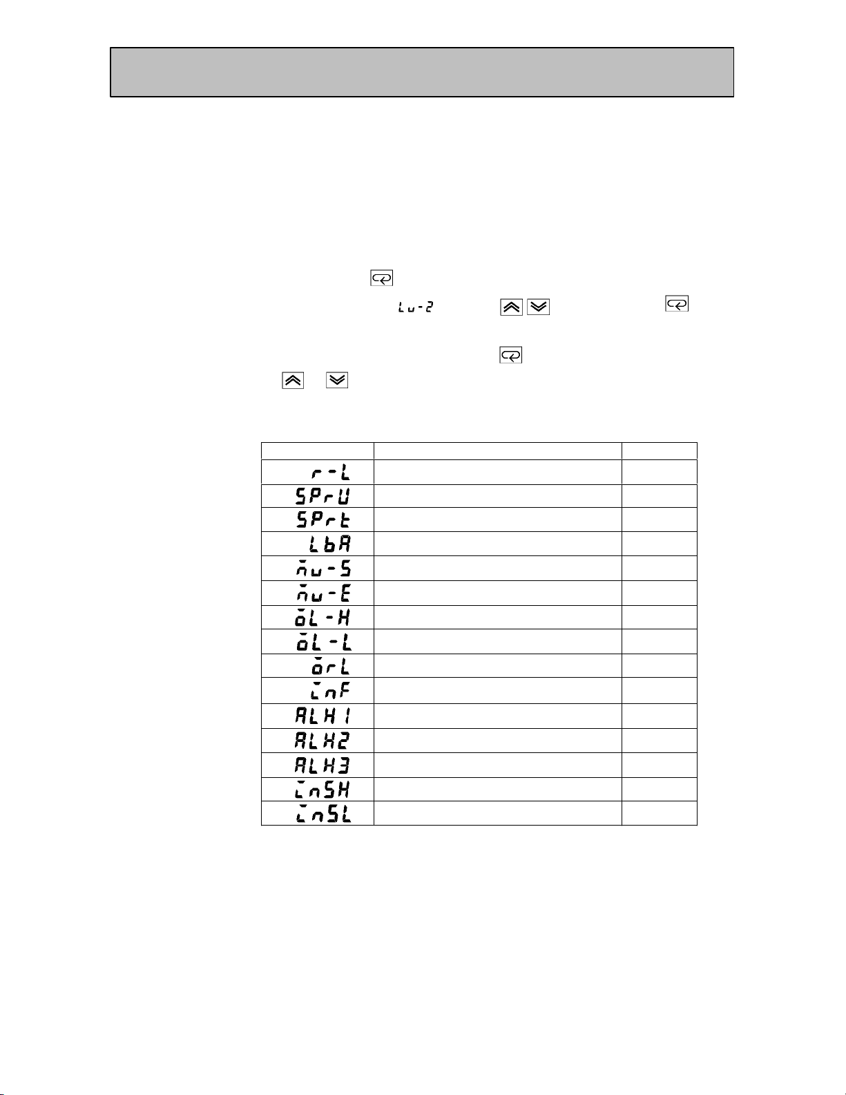
Level 2 Mode
Ă• The parameters in this mode can be used only when the security" parameter (proĆ
tect mode) is set to 0" to 2".
Ă• This mode contains the auxiliary parameters for adjusting control. These parameĆ
ters include parameters for limiting the manipulated variable and set point, parameĆ
ters for switching between remote and local operation, and parameters for setting the
LBA (Loop Break Alarm), alarm hysteresis, and input digital filter values.
Ă• To select this mode when in the levels 0 and 1, setup, expansion, option and calibraĆ
tion modes, press the
menu display. If you select [
key for 1 second minimum. The display changes to the
] using the key then press the key for
1 second minimum, the controller enters the level 2 mode.
Ă• To select parameters in this mode, press the
use the
or keys.
key. To change parameter settings,
Ă• The following table shows the parameters supported in this mode and the page where
the parameter is described.
Symbol Parameter Name Page
Remote/Local 5-16
SP ramp time unit
SP ramp set value
LBA detection time
MV at stop
MV at PV error
MV upper limit
MV lower limit
MV change rate limit
5-16
5-16
5-17
5-17
5-17
5-18
5-18
5-18
Input digital filter
Alarm 1 hysteresis
Alarm 2 hysteresis
Alarm 3 hysteresis
Input shift upper limit (temperature)
Input shift lower limit (temperature)
5-19
5-19
5-19
5-19
5-20
5-20
5–15
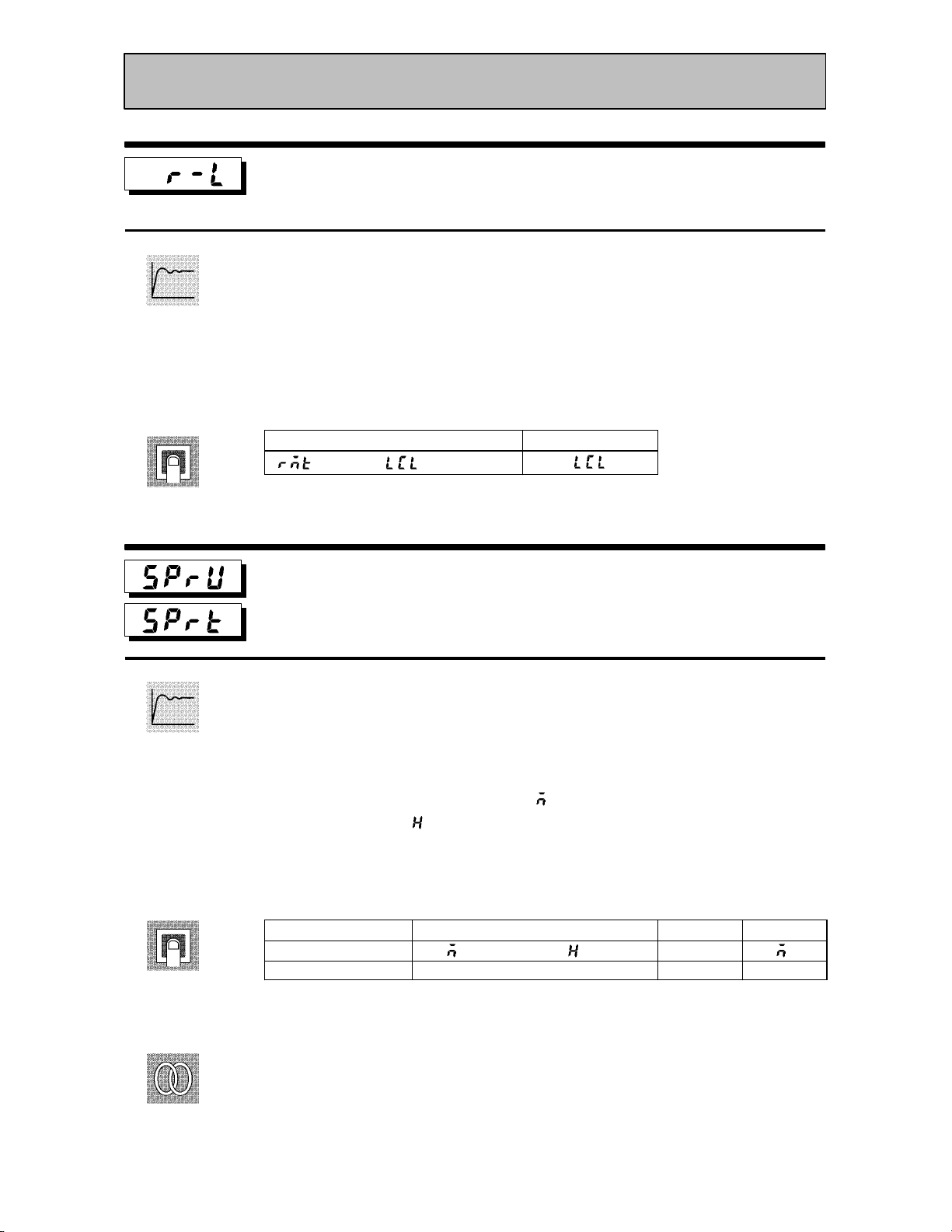
CHAPTER 5 PARAMETERS
Level 2 Mode
Function
Comment
Remote/Local
Conditions of Use
The communications function must be in
use.
Ă• Switches between remote and local operation.
Ă• To change the parameter setting during remote operation, use the communications
function. To change the parameter setting during local operation, change the setting
on the E5CK controller.
Ă• You can check the parameter setting by both communications and on the E5CK conĆ
troller regardless of whether the controller is switched to remote or local operation.
Setting Range
[ ]: remote / [ ]: local
SP ramp time unit
Default
[]
Conditions of Use
ST must be set to OFF.
SP ramp set value
Function
Comment
See
Ă• Specifies the change rate during SP ramp operation. Set the maximum permissible
change width per unit of time (minute or hour) as the SP ramp set value". However,
note that when set to 0", the SP ramp function is disabled.
Ă• The time unit and SP ramp set value are independent of each other. For example,
when setting 30 per minute", set the SP ramp set value" parameter to 30" and the
SP ramp time unit" parameter to [ĂĂĂĂĂĂ
time unit only to [ĂĂĂĂĂĂ
] (hour"), the set time becomes 30 per hour."
] (minute"). However, if you change the
Ă• During temperature input, the decimal point position of the SP ramp set value is
dependent on the currently selected sensor, and during analog input on the results
of scaling.
Parameter Setting Range
SP ramp time unit
SP ramp set value 0 to 9999 EU 0
[ ]: minute/ [ ]: hour
Unit Default
None
During temperature input, the range of the currently selected sensor it taken as the
setting range for the SP ramp set value" parameter.
FĂRelated article
4.2 Operating Condition Restrictions (page 4Ć5)
FĂRelated parameters
Input type" Scaling upper limit" Scaling lower limit" Decimal point" (setup
mode)
5–16
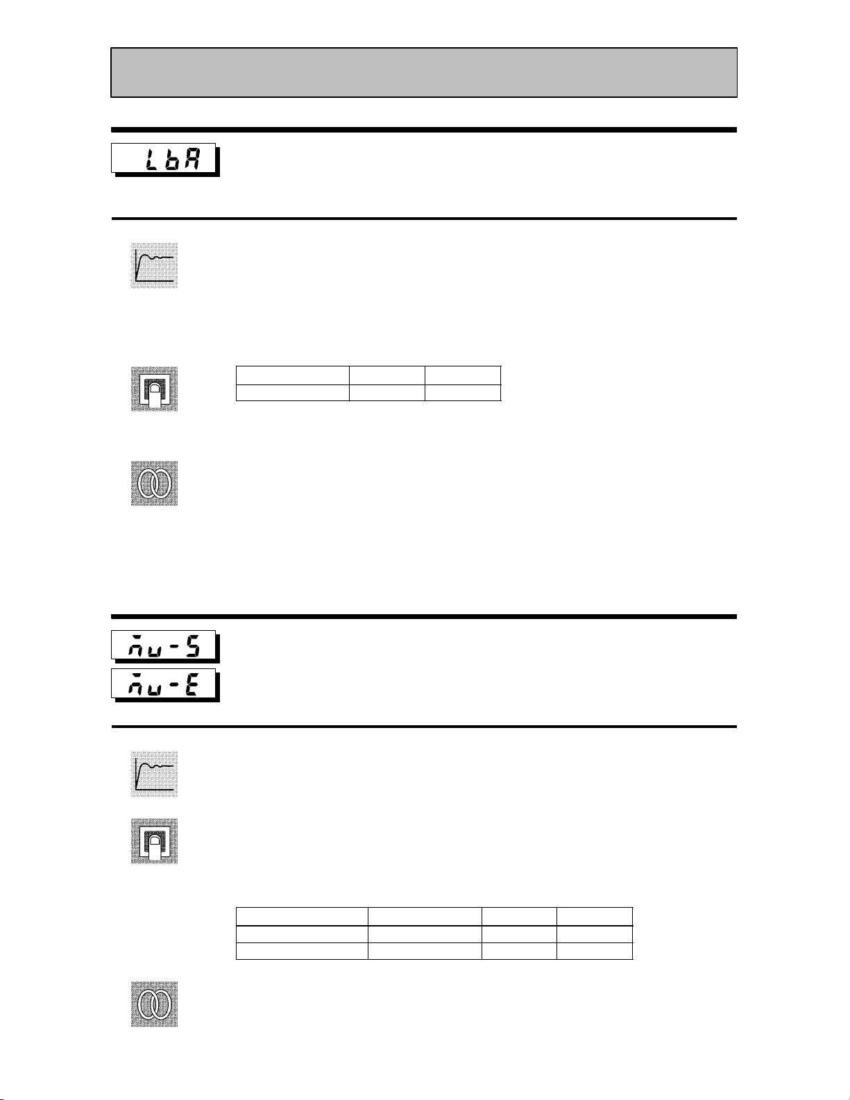
Level 2 Mode
Function
Comment
See
LBA detection time
Conditions of Use
The LBA (Loop Break Alarm) function
must be assigned as an output.
Ă• This parameter is automatically set by AT execution.
Ă• The LBA is output if the change width of the process value falls below 0.2 %fullĆscale
of the time preset to this parameter when the manipulated variable is set in the MV
upper limit" or MV lower limit" parameters.
Ă• The LBA function is disabled when this parameter is set to 0".
Setting Range
0 to 9999 Second 0
Unit Default
FĂRelated article
4.4 LBA (page 4Ć9)
7.3 How to Use Error Output (page 7Ć5)
FĂRelated parameters
AT Execute/Cancel" (level 1 mode)
Control output 1 assignment" Control output 2 assignment" Auxiliary output 1
assignment" (setup mode)
Function
Comment
See
MV at stop
MV at PV error
Ă• The MV at stop" parameter sets the manipulated variable when operation stops.
Ă• The MV at PV error" parameter sets the manipulated variable when an input error
occurs.
Ă• The setting ranges during standard control and heating and cooling control are differĆ
ent.
Ă• The manipulated variable at the cooling side during heating and cooling control is
expressed as a negative value.
Control Method Setting Range
Standard -5.0 to 105.0 % 0
Heating and cooling -105.0 to 105.0 % 0
FĂRelated articles
MV at stop : 3.6 Starting and Stopping Operation (page 3Ć11)
MV at PV error : 7.2 How to Use the Error Display (page 7Ć3)
Unit Default
5–17

CHAPTER 5 PARAMETERS
Level 2 Mode
Function
Comment
MV upper limit
Conditions of Use
The control must be advanced PID con-
MV lower limit
trol, and ST must be set to OFF.
MV change rate limit
Ă• The MV upper limit" and MV lower limit" parameters set the upper and lower limĆ
its of the manipulated variable. When the manipulated variable calculated by the
E5CK controller is outside of the upperĆand lowerĆlimit range, the upper limit or
lower limit set to these parameters is output, respectively.
Ă• The MV change rate limit" parameter sets the maximum permissible change width
per second of the manipulated variable. If a change in the manipulated variable
causes this parameter setting to be exceeded, the calculated value is reached while
changing the value by the perĆsecond value set in this parameter.
The MV change rate limit" function is disabled when this parameter is set to 0.0".
Ă• MV upper limit
The setting ranges during standard control and heating and cooling control are difĆ
ferent. Also, the manipulated variable at the cooling side during heating and cooling
control is expressed as a negative value.
See
Control Method Setting Range
Standard MV lower limit +0.1 to 105.0 % 105.0
Heating and cooling 0.0 to 105.0 % 105.0
Unit Default
Ă• MV lower limit
The setting ranges during standard control and heating and cooling control are difĆ
ferent. Also, the manipulated variable at the cooling side during heating and cooling
control is expressed as a negative value.
Control Method Setting Range
Standard -5.0 to MV upper limit -0.1 % -5.0
Heating and cooling -105.0 to 0.0 % -105.0
Unit Default
Ă• MV change rate limit
Setting Range
0.0 to 100.0 % 0.0
Unit Default
FĂRelated article
4.2 Operating Condition Restrictions (page 4Ć4)
5–18
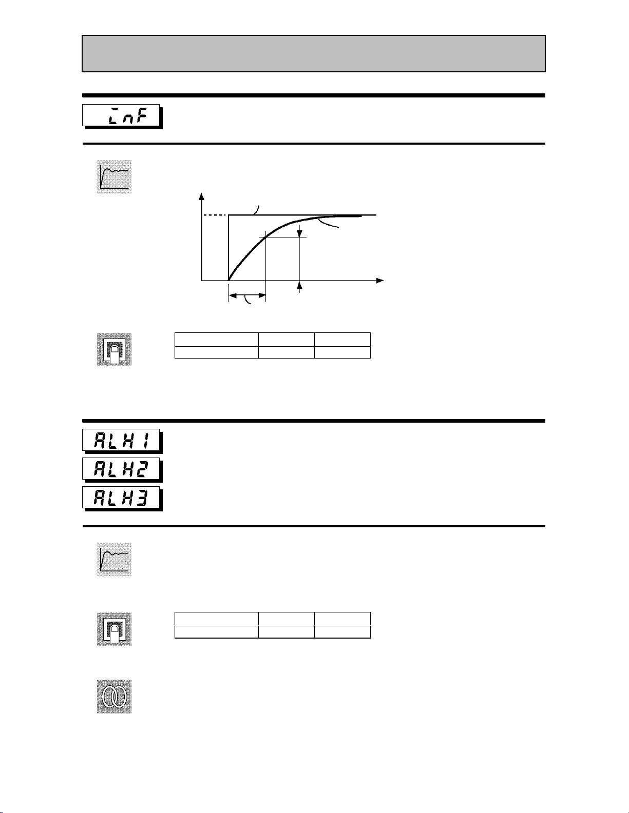
Level 2 Mode
Input digital filter
Ă• Sets the time constant of the input digital filter. The following figures shows the effect
on data after passing through the digital filter.
Function
Comment
PV before passing through filter
A
Time
constant
Input digital filter
Setting Range
0 to 9999 Second 0
Alarm 1 hysteresis
Alarm 2 hysteresis
Alarm 3 hysteresis
PV after passing through filter
0.63A
Time
Unit Default
Conditions of Use
Alarms must be assigned as outputs. For
example, if alarm outputs 1 and 2 only are
assigned as outputs, the “alarm 3 hysteresis” parameter cannot be used.
Function
Comment
See
Ă• This parameter is for checking the hysteresis of alarm outputs 1 to 3.
Setting Range
0.01 to 99.99 %FS 0.02
Unit Default
FĂRelated article
3.4 Setting Alarm Type (page 3Ć7)
FĂRelated parameters
Alarm 1 type" Alarm 2 type" Alarm 3 type" Alarm 1 open in alarm" Alarm 2 open
in alarm" Alarm 3 open in alarm" (setup mode)
Alarm value 1" Alarm value 2" Alarm value 3" (level 1 mode)
5–19

CHAPTER 5 PARAMETERS
Level 2 Mode
Function
Comment
See
Input shift upper limit
Input shift lower limit
Ă• Sets each of the shift amounts for the input shift upper and lower limit values.
Setting Range
-199.9 to 999.9 _C or _F 0.0
FĂRelated article
3.2 Setting Input Specifications (page 3Ć3)
FĂRelated parameter
Input type" (setup mode)
Unit Default
Conditions of Use
The input type must be set to temperature
input (thermocouple or platinum resistance thermometer).
5–20

Setup Mode
Ă• The parameters in this mode can be used only when the security" parameter (proĆ
tect mode) is set to 0" and 1".
Ă• This mode contains the parameters for setting the basic specifications of the E5CK
controller. These parameters include parameters for specifying the input type, scalĆ
ing, output assignments, and direct/reverse operation.
Ă• To select this mode when in the levels 0 to 2, expansion, option and calibration modes,
press the
If you select [ĂĂ
key for 1 second minimum. The display changes to the menu display.
] using the key then press the key for 1 second miniĆ
mum, the controller enters the setup mode.
Ă• To select parameters in this mode, press the
use the
or keys.
key. To change parameter settings,
Ă• The following table shows the parameters supported in this mode and the page where
the parameter is described.
Symbol Parameter Name Page
Input type 5-22
Scaling upper limit
Scaling lower limit
Decimal point
_C/_F selection
Parameter initialize
Control output 1 assignment
Control output 2 assignment
Auxiliary output 1 assignment
5-23
5-23
5-23
5-24
5-23
5-24
5-24
5-25
Alarm 1 type
Alarm 1 open in alarm
Alarm 2 type
Alarm 2 open in alarm
Alarm 3 type
Alarm 3 open in alarm
Direct/Reverse operation
5-25
5-26
5-25
5-26
5-25
5-26
5-26
5–21

CHAPTER 5 PARAMETERS
Platinum resis
Thermocouple
TC@PT
Voltage input
V
Setup Mode
Input type
Ă• Match the setting (software) of this parameter with the setting (hardware) of the
input type jumper connector.
Function
Comment
Ă• Set the input types to be connected to terminal Nos. 6 to 8 by the input type codes in
the table below.
Ă• Set the code according to the following table. Default is 2: K1 thermocouple".
Set value
0 JPt -199.9 to 650.0 (_C) /-199.9 to 999.9 (_F)
1 Pt -199.9 to 650.0 (_C) /-199.9 to 999.9 (_F)
2 K1 -200 to 1300 (_C) /-300 to 2300 (_F)
3 K2 0.0 to 500.0 (_C) /0.0 to 900.0 (_F)
4 J1 -100 to 850 (_C) /-100 to 1500 (_F)
5 J2 0.0 to 400.0 (_C) /0.0 to 750.0 (_F)
6 T -199.9 to 400.0 (_C) /-199.9 to 700.0 (_F)
7 E 0 to 600 (_C) /0 to 1100 (_F)
8 L1 -100 to 850 (_C) /-100 to 1500 (_F)
9 L2 0.0 to 400.0 (_C) /0.0 to 750.0 (_F)
10 U -199.9 to 400.0 (_C) /-199.9 to 700.0 (_F)
11 N -200 to 1300 (_C) /-300 to 2300 (_F)
12 R 0 to 1700 (_C) /0 to 3000 (_F)
13 S 0 to 1700 (_C) /0 to 3000 (_F)
14 B 100 to 1800 (_C) /300 to 3200 (_F)
15 W 0 to 2300 (_C) /0 to 4100 (_F)
16 PLII 0 to 1300 (_C) /0 to 2300 (_F)
17 4 to 20mA
18 0 to 20mA
19 1 to 5V
20 0 to 5V
21 0 to 10V
Input Type Jumper Position
Platinum resis-
tance thermometer
Thermocouple
Current input
Voltage input
TC@PT
TC@PT
I
V
5–22
See
FĂRelated article
3.2 Setting Input Specifications (page 3Ć3)
FĂRelated parameters
When input type is set to temperature input:
_C/_F selection" (setup mode)
When input type is set to voltage input or current input:
Scaling upper limit" Scaling lower limit" Decimal point" (setup mode)

Setup Mode
Function
Comment
Scaling upper limit
Conditions of Use
The input type must be set to analog input
Scaling lower limit
(voltage or current input).
Decimal point
Ă• This parameter can be used only when voltage input or current input is selected as
the input type.
Ă• When voltage input or current input is selected as the input type, scaling is carried
out. Set the scaling upper limit in the scaling upper limit" parameter and the scaling
lower limit in the scaling lower limit" parameter.
Ă• The decimal point" parameter specifies the decimal point position of parameters
(set point, etc.) whose unit is set to EU (Engineering Unit).
Ă• Scaling upper limit, Scaling lower limit
Parameter Setting Range
Scaling upper limit Scaling lower limit +1 to 9999 EU 100
Scaling lower limit -1999 to scaling upper limit -1 EU 0
Unit Default
See
Function
Ă• Decimal point : default : 0
Set Value
0
1
2
3
0 digits past decimal point
1 digit past decimal point
2 digits past decimal point
3 digits past decimal point
Setting Example
1234
123.4
12.34
1.234
FĂRelated article
3.2 Setting Input Specifications (page 3Ć3)
FĂRelated parameter
Input type" (setup mode)
Parameter initialize
Ă• Returns parameter settings to their defaults. However, note that the following
parameters are not affected by execution of this parameter:
input type", scaling upper limit", scaling lower limit", decimal point" and
_C/_F selection".
Example
of use
Ă• When this parameter is selected, [ĂĂĂ
ters, press the
key to specify [ĂĂ ] (yes").
] (no") is first displayed. To initialize parameĆ
5–23

CHAPTER 5 PARAMETERS
Setup Mode
Function
Comment
See
_C/_F selection
Conditions of Use
The input type must be set to temperature
input (thermocouple or platinum resistance thermometer).
Ă• This parameter can be used when thermocouple or platinum resistance thermometer
is selected as the input type.
Ă• Set the temperature input unit to either of _C" or _F".
Setting Range
: _C/ :_F
Default
FĂRelated article
3.2 Setting Input Specifications (page 3Ć3)
FĂRelated parameter
Input type" (setup mode)
Control output 1 assignment
Function
Comment
See
Control output 2 assignment
Ă• Assigns the output functions to either of control output 1 or 2.
Ă• The following six output functions can be assigned as outputs:
Control output (heat), Control output (cool), Alarms 1 to 3, and LBA.
Ă• Errors 1 and 2 cannot be assigned as outputs.
Ă• When the output function assigned to control output 1 is ON, the OUT1 LED lights.
However, note that the OUT1 LED does not light when control output (heat) or control
output (cool) are assigned to linear outputs such as current and voltage.
Ă• When the output function assigned to control output 2 is ON, the OUT2 LED lights.
Symbol
Function
Defaults:
Control output 1" = [
FĂRelated article
3.3 Setting Output Specifications (page 3Ć5)
FĂRelated parameters
Ă• AlarmĆrelated parameters
Ă• Heating and cooling related parameter
LBA detection time" (level 2 mode)
Control output (heat) Control output (cool)
], Control output 2" = [ ]
Alarm 1 Alarm 2 Alarm 3 LBA
5–24

Function
Comment
See
Setup Mode
Auxiliary output 1 assignment
Ă• Assigns output functions to auxiliary output 1. The following six output functions
can be assigned as outputs:
Alarms 1 to 3, LBA, Error 1 (input error), and Error 2 (A/D converter error).
Ă• Control output (heat) and control output (cool) cannot be assigned as outputs.
Ă• When the output function assigned to auxiliary output 1 is ON, the SUB1 LED lights.
Symbol
Function Alarm 1 Alarm 2 Alarm 3 LBA Error 1 Error 2
Defaults: [ ]
FĂRelated article
3.3 Setting Output Specifications (page 3Ć5)
FĂRelated parameter
Ă• AlarmĆrelated parameter
LBA detection time" (level 2 mode)
Function
Comment
See
Alarm 1 type
Conditions of Use
Alarms must be assigned as outputs. For
Alarm 2 type
example, if alarm outputs 1 and 2 only are
assigned as outputs, the ”alarm 3 type”
Alarm 3 type
parameter cannot be used.
Ă• Alarm 1 to 3 type" parameters specify the operation of the alarm by the one of the
set values in the following table. For details of operation at an alarm, see page 3Ć7.
Set Value Settings Set Value Settings
1 Upper-and lower-limit alarm
(deviation)
2 Upper-limit alarm (deviation) 8 Absolute-value upper-limit alarm
3 Lower-limit alarm (deviation) 9 Absolute-value lower-limit alarm
4 Upper-and lower-limit range alarm
(deviation)
5 Upper-and lower-limit alarm with
standby sequence (deviation)
6 Upper-limit alarm with standby
sequence (deviation)
7 Lower-limit alarm with standby
sequence (deviation)
10 Absolute-value upper-limit alarm with
standby sequence
11 Absolute-value lower-limit alarm with
standby sequence
Defaults: Deviation upper limit
FĂRelated article
3.4 Setting Alarm Type (page 3Ć7)
FĂRelated parameters
Alarm value 1" Alarm value 2" Alarm value 3" (level 1 mode)
Alarm 1 hysteresis" Alarm 2 hysteresis" Alarm 3 hysteresis" (level 2 mode)
Alarm 1 open in alarm" Alarm 2 open in alarm" Alarm 3 open in alarm" Control
output 1 assignment" Control output 2 assignment" (setup mode)
5–25

CHAPTER 5 PARAMETERS
Cl
O
Setup Mode
Function
Comment
See
Alarm 1 open in alarm
Conditions of Use
Alarms must be assigned as outputs. For
Alarm 2 open in alarm
example, if alarm outputs 1 and 2 only are
assigned as outputs, the alarm 3 open in
Alarm 3 open in alarm
alarm” parameter cannot be used.
Ă• Selects the output states of alarms 1 to 3.
Ă• When the controller is set to "close in alarm," the status of the alarm output function
is output as it is. When set to "open in alarm," the status of the alarm output function
is output inverted. The following table shows the relationship between alarm output
functions, output and output LEDs.
Alarm
osein alarm
penin alarm
Setting Range
: Close in alarm/ :Open in alarm
ON ON Lit
OFF OFF Not lit
ON OFF Lit
OFF ON Not lit
Output Output LED
Default
FĂRelated article
3.3 Setting Output Specifications (page 3Ć5)
FĂRelated parameters
Alarm value 1" Alarm value 2" Alarm value 3" (level 1 mode)
Alarm 1 hysteresis" Alarm 2 hysteresis" Alarm 3 hysteresis" (level 2 mode)
Alarm 1 open in alarm" Alarm 2 open in alarm" Alarm 3 open in alarm"
Control output 1 assignment" Control output 2 assignment" (setup mode)
5–26
Function
Comment
See
Direct/Reverse operation
Ă• Direct operation" (or normal operation) refers to control where the manipulated
variable is increased according to the increase in the process value. Alternatively,
reverse operation" refers to control where the manipulated variable is increased
according to the decrease in the process value.
Setting Range
: Reverse operation/ :Direct operation
FĂRelated article
3.3 Setting Output Specifications (page 3Ć5)
Default
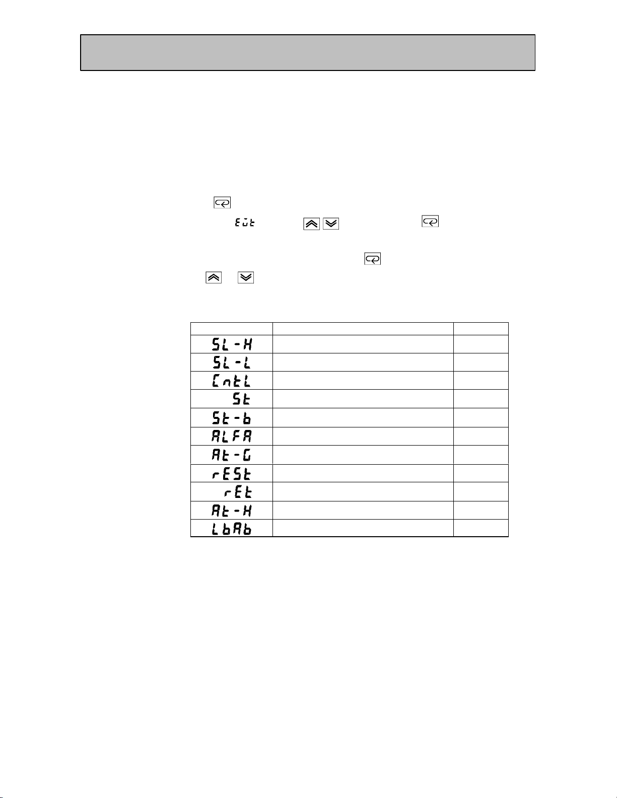
Expansion Mode
Ă• The parameters in this mode can be used only when the security" parameter (proĆ
tect mode) is set to 0" and 1".
Ă• This mode contains the parameters for setting expanded functions. These parameĆ
ters include parameters for setting ST (selfĆtuning), setting the SP setting limiter,
selecting advanced PID and ON/OFF control, specifying the standby sequence reset
method, and automatic return of display mode.
Ă• To select this mode when in the levels 0 to 2, setup, option and calibration modes,
press the
If you select [ĂĂĂ
key for 1 second minimum. The display changes to the menu display.
] using the key then press the key for 1 second miniĆ
mum, the controller enters the expansion mode.
Ă• To select parameters in this mode, press the
use the
or keys.
key. To change parameter settings,
Ă• The following table shows the parameters supported in this mode and the page where
the parameter is described.
Symbol Parameter Name Page
Set point upper limit 5-28
Set point lower limit 5-28
PID / ON/OFF 5-28
ST 5-29
ST stable range 5-29
α 5-29
AT calculated gain 5-30
Standby sequence reset method 5-30
Automatic return of display mode 5-31
AT hysteresis 5-31
LBA detection width 5-31
5–27
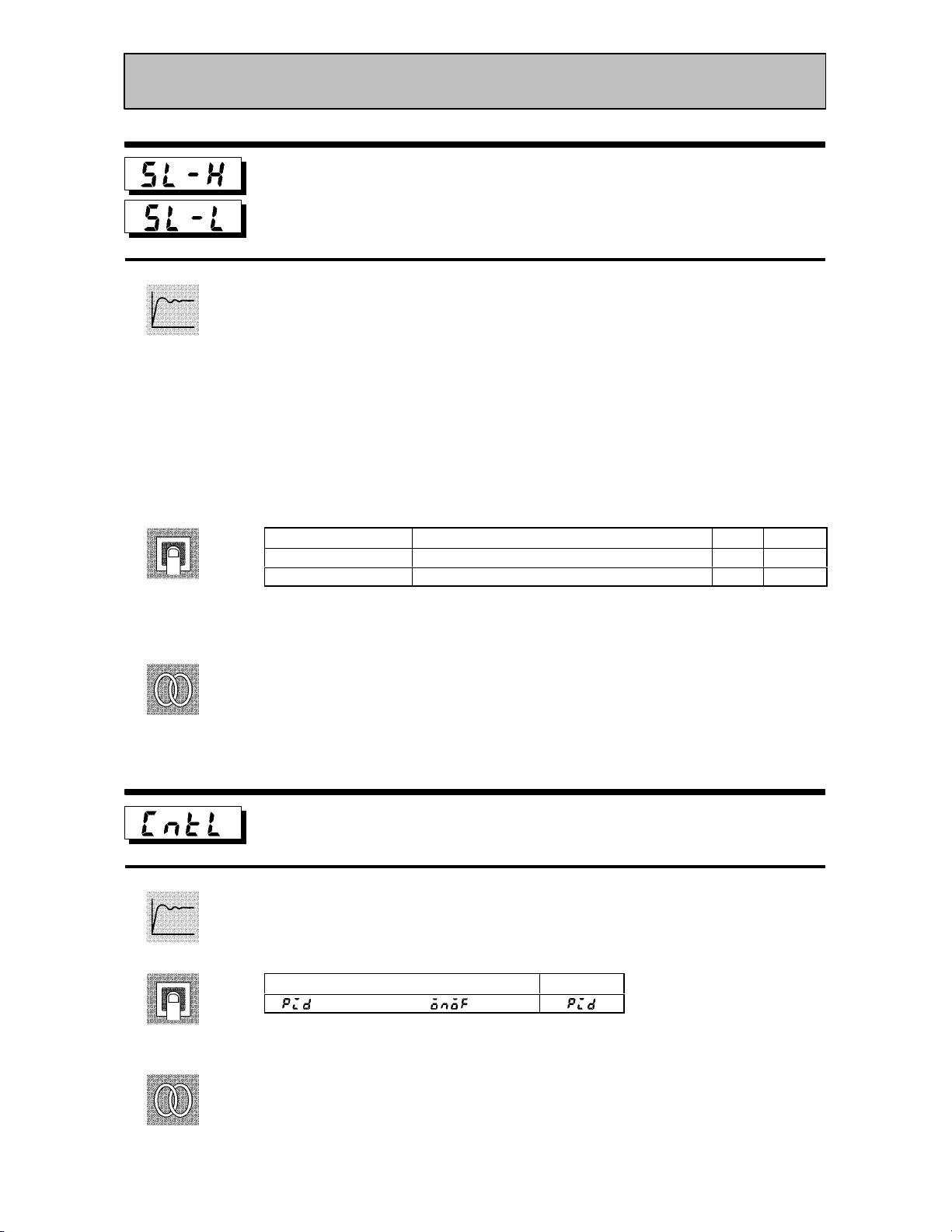
CHAPTER 5 PARAMETERS
Expansion Mode
Set point upper limit
Set point lower limit
Ă• Limits the upper and lower limits of the set point. When the set point exceeds the setĆ
tings of the Set point upper limit" and Set point lower limit" parameters, the E5CK
Function
controller regards the settings of the Set point upper limit" and Set point lower
limit" parameters as the set points.
Ă• When the input type is changed to temperature input, the set point upper and lower
limits are changed to the upper and lower limits of the currently selected sensor. And
when the input type is changed to analog input, the set point upper and lower limits
are changed to the scaling upper and lower limits.
Ă• During temperature input, the decimal point position is dependent on the currently
selected sensor, and during analog input on the results of scaling.
Comment
See
Function
Parameter Setting Range
SP setting upper limit SP setting lower limit +1 to scaling upper limit EU 1300
SP setting lower limit Scaling lower limit to SP setting upper limit -1 EU -200
Unit Default
During temperature input, the range becomes the range of use of the selected sensor
instead of the scaling upper and lower limit values.
FĂRelated article
4.2 Operating Condition Restrictions (page 4Ć5)
FĂRelated parameters
Input type" Scaling upper limit" Scaling lower limit" Decimal point" (setup
mode)
PID / ON/OFF
Ă• Selects advanced PID control or ON/OFF control.
Setting Range
: advance PID/ :ON/OFF
Default
5–28
Comment
See
FĂRelated article
4.1 Selecting the Control Method (page 4Ć3)
FĂRelated parameters
Hysteresis (heat)" Hysteresis (cool)" (level 1 mode)
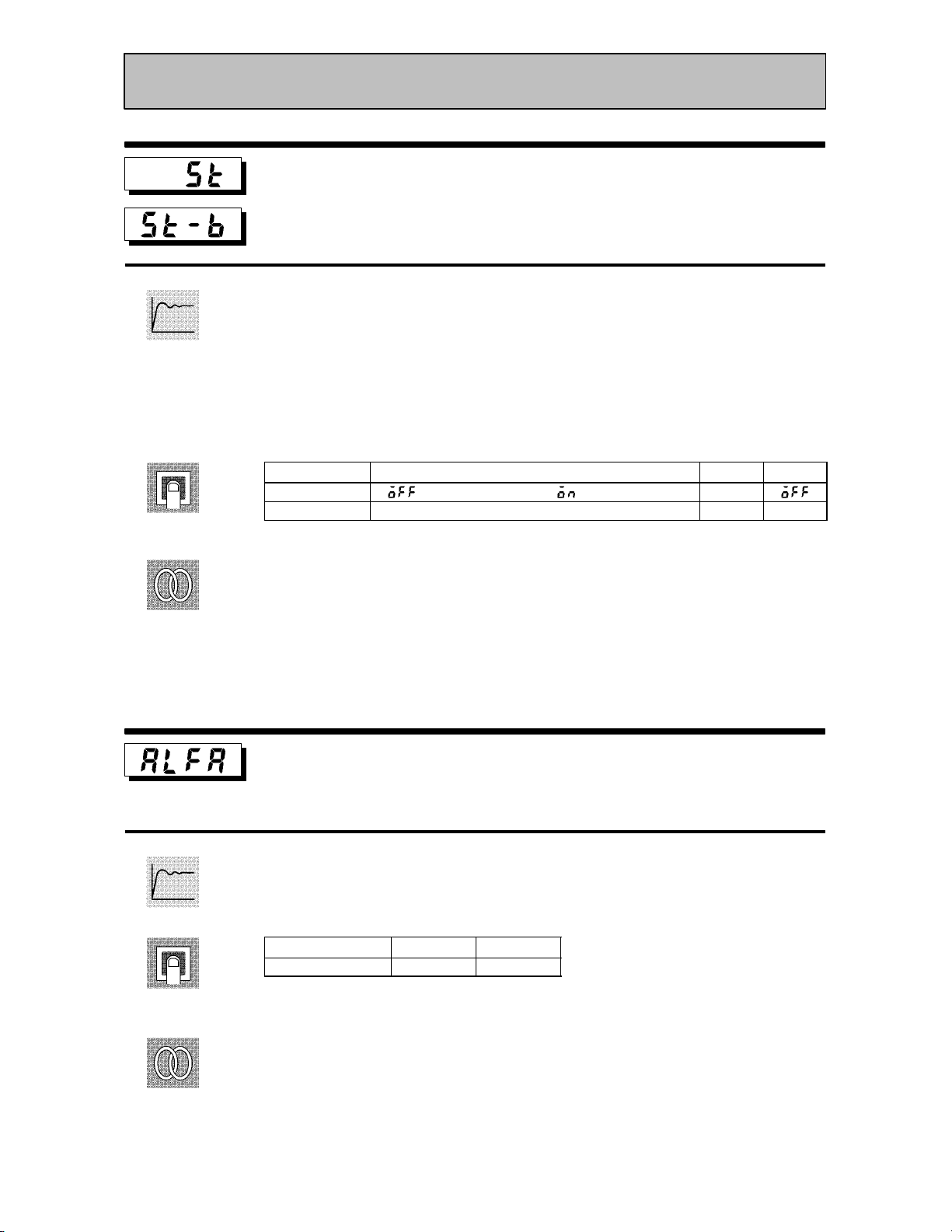
Expansion Mode
Function
Comment
See
ST
Conditions of Use
The input type must be set to temperature
input, and the control must be either stan-
ST stable range
dard control or advanced PID control.
Ă• When the ST" parameter is set to ON", the selfĆtuning (ST) function is active. DurĆ
ing operation of the ST function, the power on the load side connected to the control
output must be turned ON at the same time or before start of E5CK operation.
Ă• The ST stable range" parameter sets the stable range width during selfĆtuning.
However, note that this parameter cannot be used when the ST" parameter is set to
OFF".
Parameter Setting Range
ST : ST function OFF/ : ST function ON None
ST stable range 0.1 to 999.9 _C or _F 15.0
Unit Default
FĂRelated article
Fuzzy selfĆtuning (page AĆ10)
FĂRelated parameters
Input type" (setup mode)
PID / ON/OFF" (expansion mode)
Function
Comment
See
α
Ă• Sets advanced PIDĆcontrol parameter α.
Setting Range
0.00 to 1.00 None 0.65
FĂRelated parameter
PID / ON/OFF" (expansion mode)
Unit Default
Conditions of Use
The control must be advanced PID control, and ST must be set to OFF.
5–29

CHAPTER 5 PARAMETERS
Expansion Mode
Function
Comment
See
AT calculated gain
Conditions of Use
The control must be advanced PID control, and ST must be set to OFF.
Ă• Sets the gain when adjusting the PID parameters by autoĆtuning.
Ă• To give priority to response, decrease the set value of this parameter. To give priority
to stability, increase the set value of this parameter.
Setting Range
0.1 to 10.0 None 1.0
Unit Default
FĂRelated parameters
AT Execute/Cancel" (level 1 mode)
PID / ON/OFF" (expansion mode)
Standby sequence reset method
Function
Comment
See
Ă• Selects the conditions for enabling reset after the standby sequence of the alarm has
been canceled.
Ă• Condition A:
Control started (including power ON), and set point, alarm value or input shift value
changed, and when set points 1 and 2 are switched.
Ă• Condition B:
Power ON
Setting Range
0: Condition A / 1: Condition B 0
Default
FĂRelated parameters
Alarm 1 type" Alarm 2 type" Alarm 3 type" (setup mode)
5–30
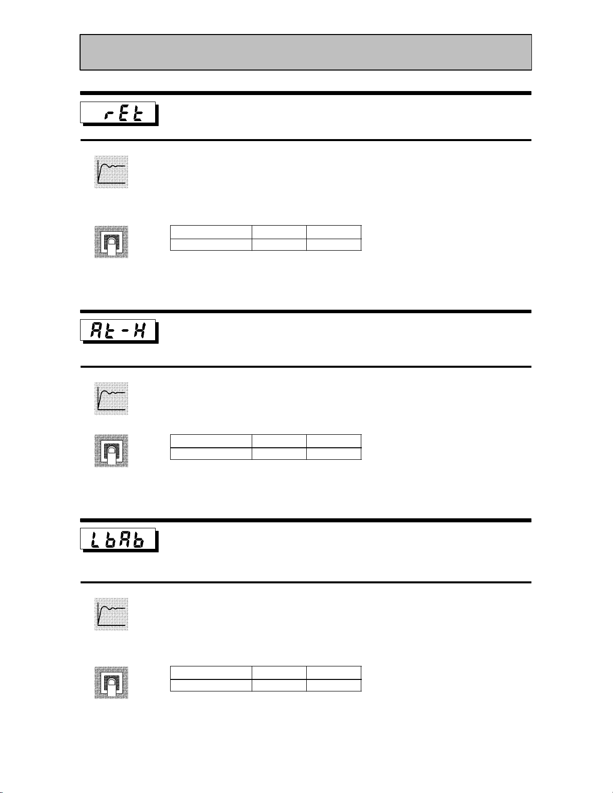
Function
Expansion Mode
Automatic return of display mode
Ă• If you do not operate any of the controller keys for the time set in this parameter when
in levels 0 to 2 modes, the display automatically returns to the PV/SP display.
Ă• When this parameter is set to 0", this function is disabled.
Ă• This parameter is invalid while the menu is displayed.
Comment
Function
Comment
Setting Range
0 to 99 Second 0
AT hysteresis
Unit Default
Conditions of Use
The control must be advanced PID control, and ST must be set to OFF.
Ă• The levels of limit cycle operations during AT execution are given hysteresis at event
ON/OFF switching. This parameter sets this hysteresis width.
Setting Range
0.1 to 9.9 %FS 0.2
Unit Default
Function
Comment
LBA detection width
Conditions of Use
The LBA (Loop Break Alarm) function
must be assigned as an output.
Ă• This parameter can be used when LBA is assigned as an output.
Ă• When the change width of the manipulated variable is below the width set in this
parameter, the controller regards this as detection of an LBA.
Setting Range
0.0 to 999.9 %FS 0.2
Unit Default
5–31
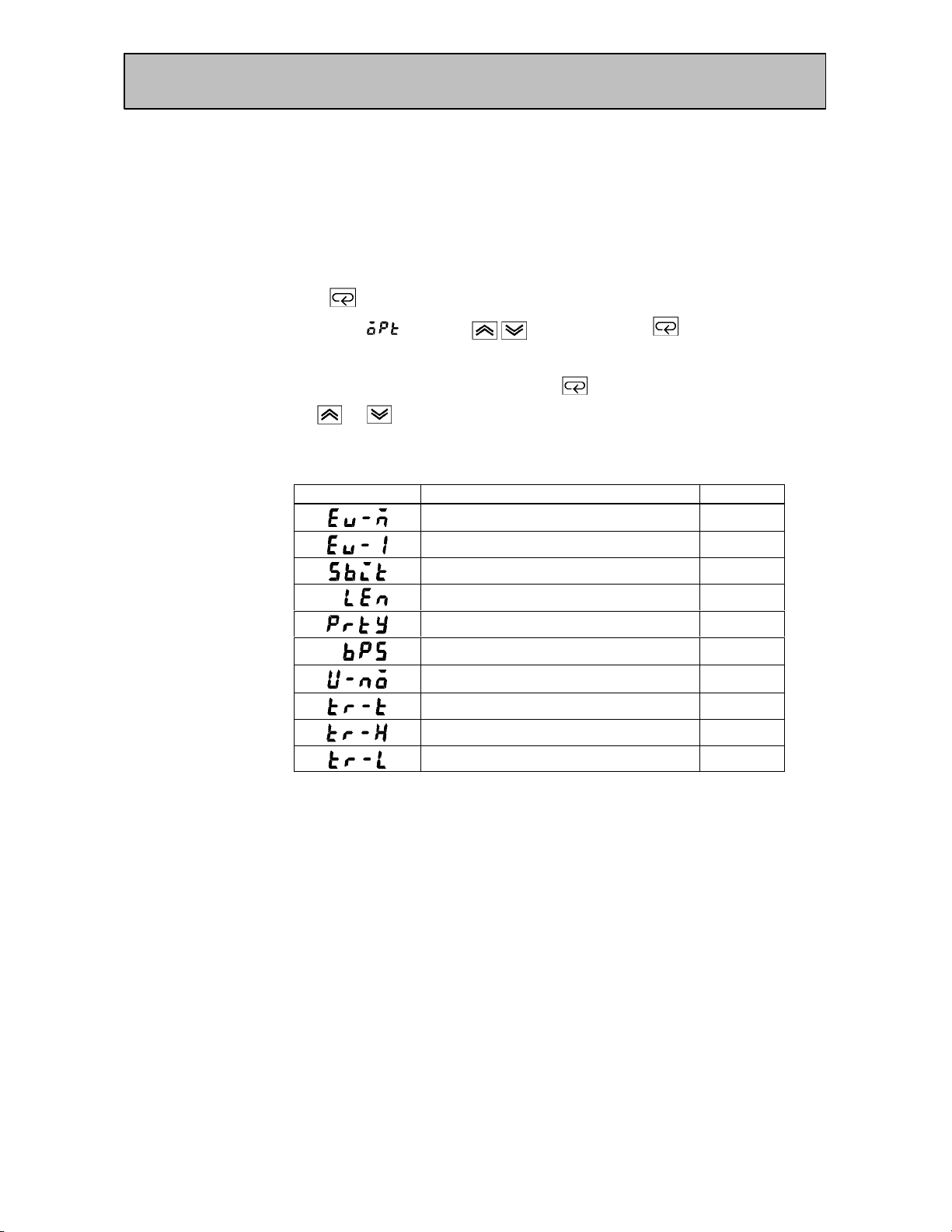
CHAPTER 5 PARAMETERS
Option Mode
Ă• The parameters in this mode can be used only when the security" parameter (proĆ
tect mode) is set to 0" and 1".
Ă• You can select this mode only when the option unit is set in the controller. In this
mode, you can set the communications conditions, transfer output and event input
parameters to match the type of option unit set in the controller.
Ă• To select this mode when in the levels 0 to 2, setup, expansion and calibration modes,
press the
If you select [ĂĂĂĂ
key for 1 second minimum. The display changes to the menu display.
] using the key then press the key for 1 second miniĆ
mum, the controller enters the option mode.
Ă• To select parameters in this mode, press the
use the
or keys.
key. To change parameter settings,
Ă• The following table shows the parameters supported in this mode and the page where
the parameter is described.
Symbol Parameter Name Page
Multi-SP function 5-33
Event input assignment 1 5-33
Communication stop bit 5-34
Communication data length 5-34
Communication parity 5-34
Communication baud rate 5-34
Communication unit No. 5-34
Transfer output type 5-35
Transfer output upper limit 5-35
5–32
Transfer output lower limit 5-35
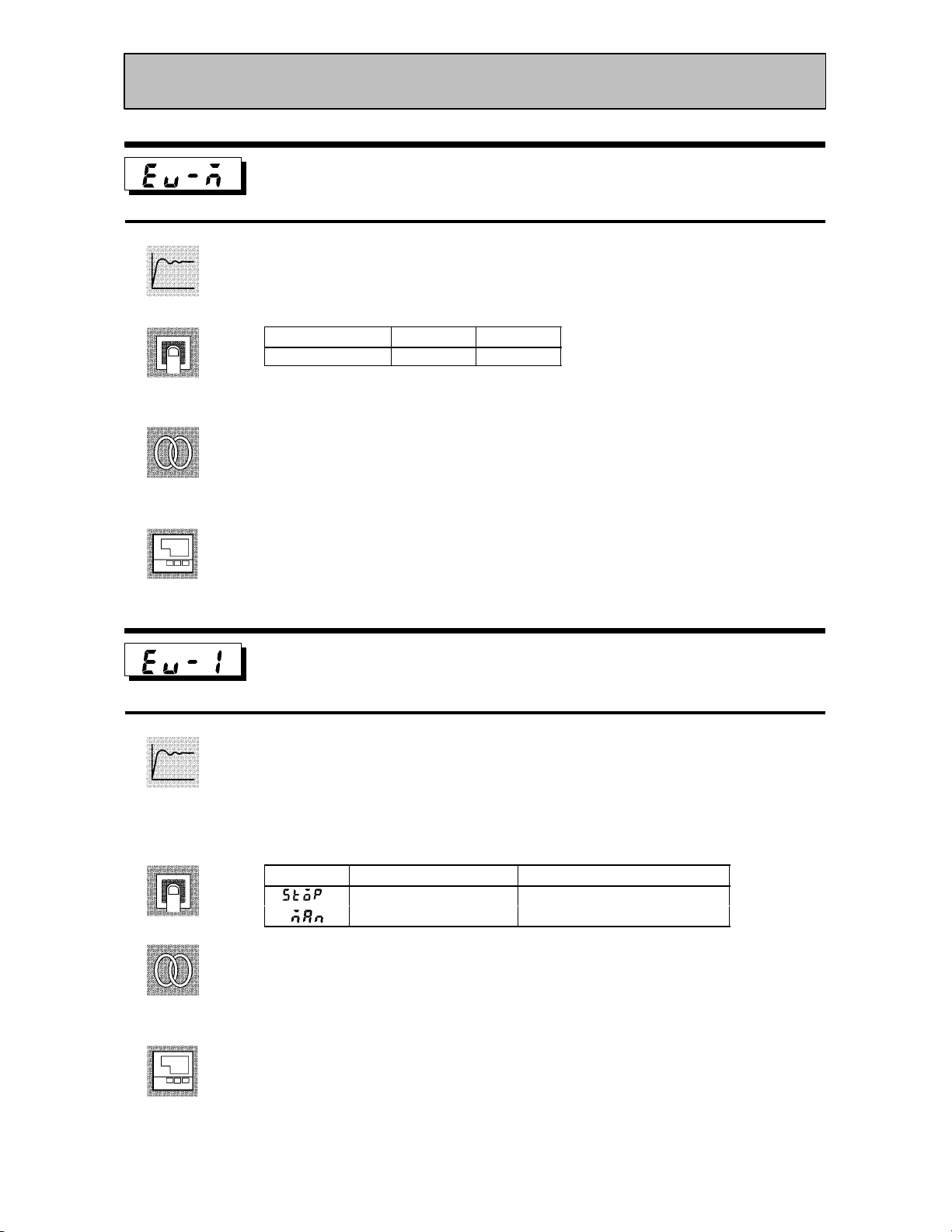
Option Mode
Function
Comment
See
Model
Multi-SP function
Conditions of Use
The event input function must be in use.
Ă• This parameter specifies the number of set points (SP) when using the multiĆSP funcĆ
tion. When set to 0", the multiĆSP function cannot be used.
Setting Range
0 to 1 None 0
Unit Default
FĂRelated article
4.3 How to Use Option Functions (4Ć7)
FĂRelated parameter
Event input assignment 1" (option mode)
FĂOption unit
Event input unit (E53ĆCKB)
Function
Comment
See
Model
Event input assignment 1
Conditions of Use
Event input must be specified when the
event input function is in use.
Ă• This parameter specifies event input other than the multiĆSP function. The following
two functions can be specified:
Run/Stop and Manual/Auto.
Ă• Event input is disabled while the menu is displayed.
It is also disabled in set up, expantion, option and calibration modes.
Symbol Function Event Input Operation
Run/Stop ON: Stop, OFF : Run
Manual/Auto ON: Manual, OFF : Auto
FĂRelated article
4.3 How to Use Option Functions (page 4Ć7)
FĂRelated parameter
Event input assignment 1" (option mode)
FĂOption unit
Event input unit (E53ĆCKB)
5–33

CHAPTER 5 PARAMETERS
Option Mode
Function
Comment
Communication stop bit
Communication data length
Communication parity
Conditions of Use
Communication baud rate
Communication unit No.
The communications function must be in
use.
Ă• These parameters set the communications conditions. Make sure that the stop bit,
data length, parity and baud rate of the host computer and the E5CK controller are
matching. These parameters are valid when the power is turned ON again or when
level 0 to 2 modes are switched.
Ă• When connecting two or more E5CK controllers to the host computer, set unit Nos.
that will not conflict with the unit Nos. of other controllers.
Ă• Communication stop bit" parameter
Setting Range
1, 2 Bits 2
Unit Default
Ă• Communication data length" parameter
Setting Range
7, 8 Bits 7
Unit Default
See
Model
Ă• Communication parity" parameter
Setting
: None/ :Even/ :Odd
Default
Ă• Communication baud rate" parameter
Setting Range
1.2, 2.4, 4.8, 9.6, 19.2 kbps 9.6
Unit Default
Ă• Communication unit No." parameter
Setting Range
0 to 99 None 0
Unit Default
FĂRelated article
Capter 6 Using the Communications Function (page 6Ć1)
FĂRelated parameter
Remote/Local" (level 2 mode)
FĂOption unit
RSĆ232C unit (E53ĆCK01), RSĆ485 unit (E53ĆCK03)
5–34

Option Mode
Function
Transfer output type
Conditions of Use
The transfer output function must be in
use.
Transfer output upper limit
Transfer output lower limit
Ă• These parameters set the transfer output conditions.
Ă• The transfer output type" parameter selects one of the following as the transfer outĆ
put type, and assigns this to transfer output:
Set point, Set point during SP ramp, Process value, Manipulated variable (heat), and
Manipulated variable (cool).
However, note that manipulated variable (cool)" can be selected only during heating
and cooling control.
Ă• The transfer output upper limit" and transfer output lower limit" parameters are
used for scaling of transfer output. The setting range varies according to this output
data. Also, a lower limit value larger than the upper limit value may be set.
Ă• During temperature input, the decimal point position of the set point, set point durĆ
ing SP ramp or process value is dependent on the currently selected sensor, and durĆ
ing analog input on the results of scaling.
Comment
See
Model
Transfer Type
Set point
Set point during SP ramp
Process value
Manipulated variable (heat)
Manipulated variable (cool)
Set point lower limit value to Set point upper limit value
Set point lower limit value to Set point upper limit value
Scaling lower limit to scaling upper limit
-5.0% to 105.0%
0.0% to 105.0%
Transfer Output Lower Limit to
Transfer Output Upper Limit
Ă• The output ranges of the set point, set point during SP ramp or process value when
temperature input is selected are the ranges supported by the selected sensor.
Ă• When you have selected the manipulated variable (heat)" parameter, the transfer
output lower limit during heating and cooling control becomes 0.0".
FĂRelated article
4.3 How to Use Option Functions (page 4Ć8)
FĂOption unit
Transfer output unit (E53ĆCKF)
5–35

CHAPTER 5 PARAMETERS
Calibration Mode
Ă• The parameters in this mode can be used only when the security" parameter (proĆ
tect mode) is set to 0". When selecting this mode for the first time after the E5CK
has left the factory, return the security" parameter to 0".
Ă• This mode contains the parameters for user calibration of inputs and outputs. Only
parameters relating to input types specified in the input type" parameter (setup
mode) can be used. Also, related output parameters can be used only when the comĆ
munications unit (E53ĆCKF) is added on.
Ă• To select this mode when in the levels 0 to 2, setup, expansion and option modes, press
the
select [ĂĂĂ
the controller enters the calibration mode.
Ă• For details on parameters in the calibration mode, see 4.5 Calibration (page 4Ć11).
key for 1 second minimum. The display changes to the menu display. If you
] using the key then press the key for 1 second minimum,
5–36

CHAPTER 6 USING THE COMMUNICATIONS FUNCTION
CHAPTER6
CHAPTER 6
USING THE
COMMUNICATIONS
FUNCTION
This chapter mainly describes communications with a host computer
and communications commands.
6.1 Outline of
the Communications Function 6-2. . . . . . . . . .
Outline 6-2. . . . . . . . . . . . . . . . . . . . . . . . . . . . . . .
Transfer procedure 6-2. . . . . . . . . . . . . . . . . . . . .
Interface 6-2. . . . . . . . . . . . . . . . . . . . . . . . . . . . . .
6.2 Preparing for Communications 6-3. . . . . . . . . .
Cable connections 6-3. . . . . . . . . . . . . . . . . . . . . .
Setting the communications
specifications 6-4. . . . . . . . . . . . . . . . . . . . . . . . . .
6.3 Command Configuration 6-5. . . . . . . . . . . . . . . .
6.4 Commands and Responses 6-6. . . . . . . . . . . . . .
Reading/writing parameters 6-6. . . . . . . . . . . . .
Issuing special commands 6-9. . . . . . . . . . . . . . .
6.5 How to Read Communications
Error Information 6-10. . . . . . . . . . . . . . . . . . . . .
Undefined error 6-11. . . . . . . . . . . . . . . . . . . . . . . .
6.6 Program Example 6-12. . . . . . . . . . . . . . . . . . . . . .
How to use programs 6-12. . . . . . . . . . . . . . . . . . .
Program list (language: IBM PC) 6-13. . . . . . . .
Examples of use 6-14. . . . . . . . . . . . . . . . . . . . . . . .
6–1
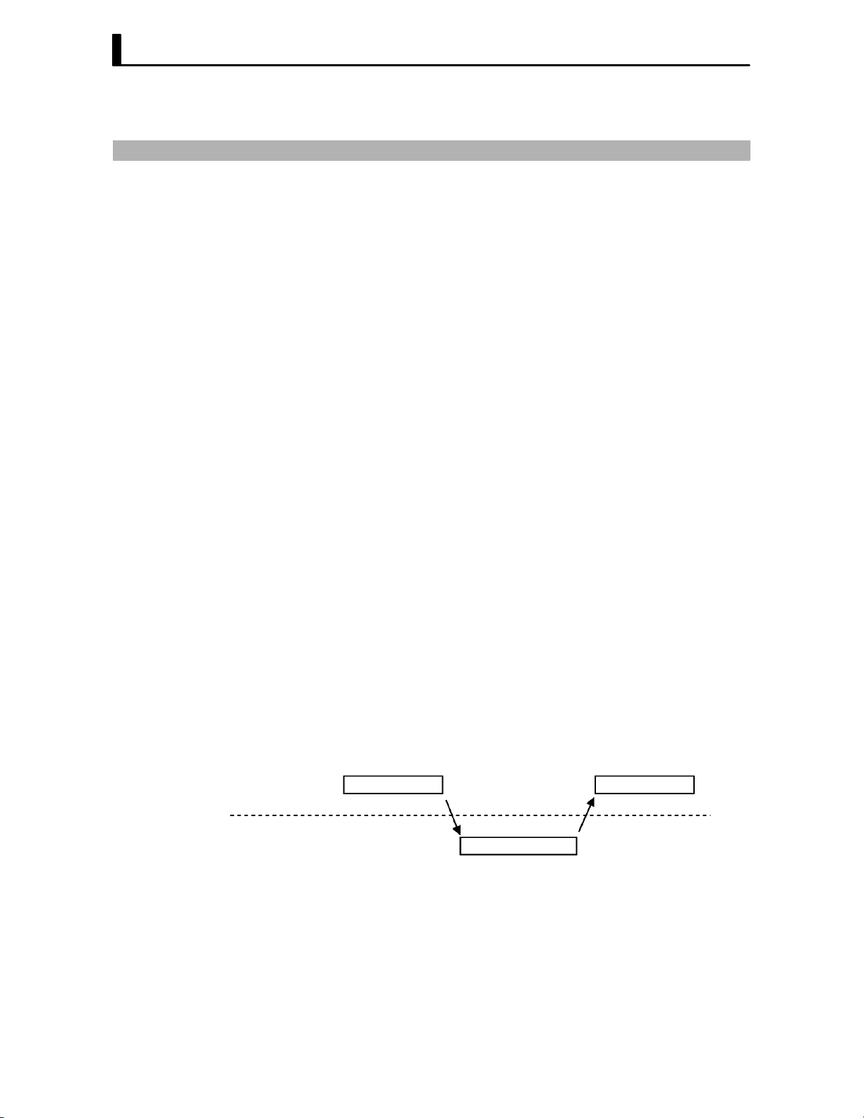
CHAPTER 6 USING THE COMMUNICATIONS FUNCTION
6.1 Outline of the Communications Function
JOutline
The communications function allows you to monitor and set E5CK
parameters by a program prepared and running on a host computer conĆ
nected to the E5CK controller. This chapter describes operations as
viewed from the host computer.
When using the communications function, the option unit for RSĆ232C or
RSĆ485 communications must be added on. The E5CK communications
function allows you to carry out the following:
Ă• Reading/writing of parameters;
Ă• Operation instructions; and
Ă• Selecting the setting level.
The communications function assumes the following conditions:
Ă• Writing of parameters is possible in during remote operation. Also,
parameters cannot be written during execution of autoĆtuning;
Ă• Writing parameters are provided with a setting level. Writing conditions
are as follows depending on the setting level:
Setting level 1: No restrictions
Setting level 0: Writing of parameters in the setup and expansion modes
only is prohibited.
Ă• For details on switching between setting levels, see page 6Ć9.
Ă• The run/stop", remote/local" and AT execute/cancel" parameters are
set aside from other parameters as special commands for instructing
operations.
JTransfer
procedure
JInterface
Host computer
E5CK
The host computer sends a command frame" to the controller, and the
controller returns a response frame" corresponding to the content of the
command sent by the host computer. In other words, a response frame is
returned for each command frame sent.
The following diagram shows command frame/response frame operaĆ
tions.
Command frame
Response frame
The host computer carries out communications conforming to the
RSĆ232C or RSĆ485 interface specifications.
Option units supporting the RSĆ232C and RSĆ485 specifications are as folĆ
lows:
Ă• Option units
E53ĆCK01 (RSĆ232C)
E53ĆCK03 (RSĆ485)
Command frame
6–2
 Loading...