

Super Manual Fiber Amplifier
E3X-NA
E3X-NA
Adjuster type standard that is the culmination of true ease and simplicity
Features
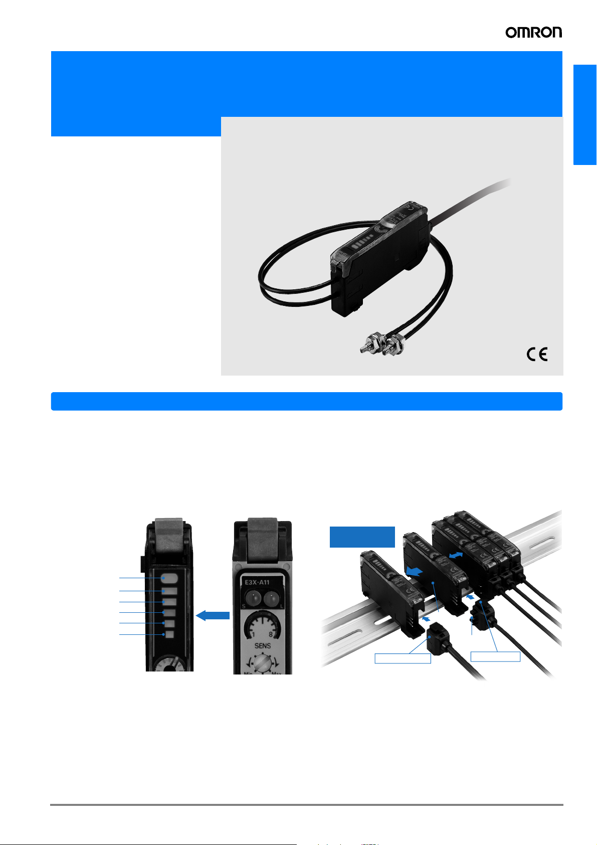
Instinctive LED bar displays of light levels
The previous manual type used the stability and incident level
indicators to display the light level change, which was difficult
to understand at a glance. The E3X-NA uses the LED bars to
display the light level, ensuring the light level change at a
glance.
Operation indicator
Approx. 20% or lower
Approx. 10% or lower
Unstable level
Approx. -10% or higher
Approx. -20% or higher
* The vertical movement
of the LED light level
and operation display
shows the light level
at a glance.
E3X-NA Conventional model
Same "Wire-saving" Connector as
E3X-DA-N
OMRON's original wiring-saving connector, which was inherited from the digital fiber amplifier E3X-DA-N, allows connection of up to 16 units.
Gang-mount up
to 16 Amplifiers
Optical
commu nications
Power supply
pin
Master connector
Slave connector
A-373E3X-NA
Features
o
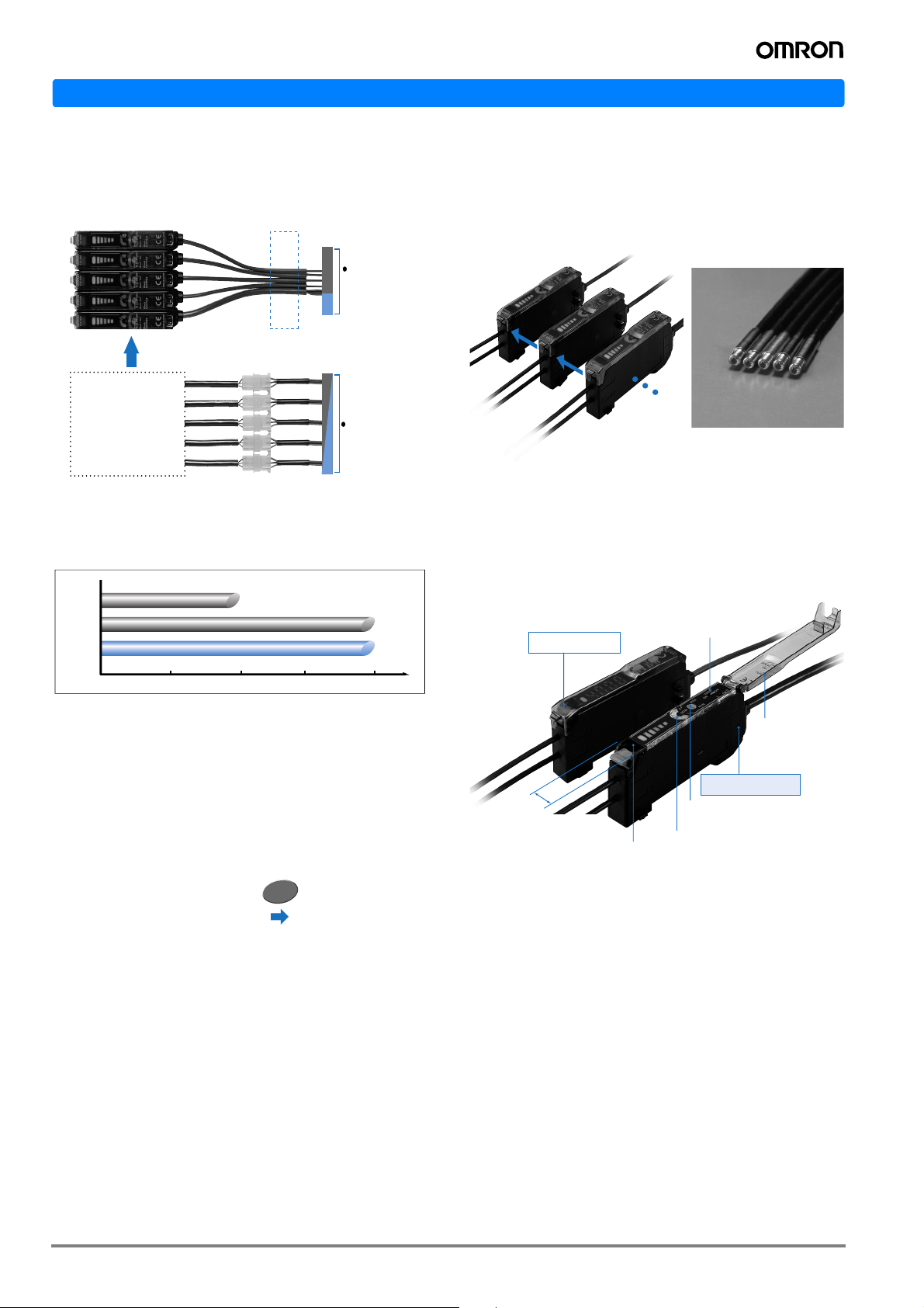
Reduced wiring and space requirements for
power lines
Example for 5 Amplifiers E3X-NA Series
E3X-NA series
Example for 5 Amplifiers
No relay connectors
required.
Less space
required.
7 lines
Power supplied from
master amplifier
through master
connector to
slave amplifiers.
Output lines separate
from power
Reduced Wiring and Space Requirements for Power Lines
15 lines
Five previous
amplifiers
Relay connectors
Power and output
lines required
for each amplifier.
Output lines and power lines
Same Sensing Distance as Previous Longdistance Models
200 mm Reflective Models
Optical Communications to Prevent Mutual
Interference
Optical communication between amplifiers prevents mutual
interference. Up to 5 fiber heads can be installed closely, except E3X-NA#F.
Optical
commu
nications
Up to 5
Amplifiers
Dimensions and Designs Inherited from the
E3X-DA-N Digital Fiber Amplifier
Standard:
E3X-A
Long-distance:
E3X-H
E3X-NA
50
mm
Note: The above characteristics are ensured
with the E32-D11L Reflective Sensor
(long-distance model).
100mm
100
mm
Standard model
150
mm
* The E3X-NA Series does not
have a long-distance model.
200
mm
200
mm
Sensing
distance
Approximately Seven Times the Detection
Accuracy
Applied Fiber: E32-T16P (screen fiber) set at 100 mm. E3XA1 1 (previous model) Minimum detection object: 2.0 mm dia.
E3X-NA 0.3 mm dia.
Applied Fiber: E32-T16 (screen fiber) set at 100 mm.
Minimum
detection object:
E3X-A11 (previous model) E3X-NA
2.0 mm dia. 0.3 mm dia.
7 times
Addition of high-speed type and waterproof
type to the series
Digital Fiber Amplifier
E3X-DA-N
10mm
Same 10-mm width as
the E3X-DA-N Digital
Fiber Amplifier
(Previously 12 mm)
Standard-feature
OFF delay timer
Super manual Amplifier
E3X-NA
8-turn adjustment knob for
precise adjustment (with indicator)
Easy-to-see indicator
Same shape as the E3X-DA-N Digital Fiber Amplifier
Non-removable hinged c
A-374 Photoelectric Sensors
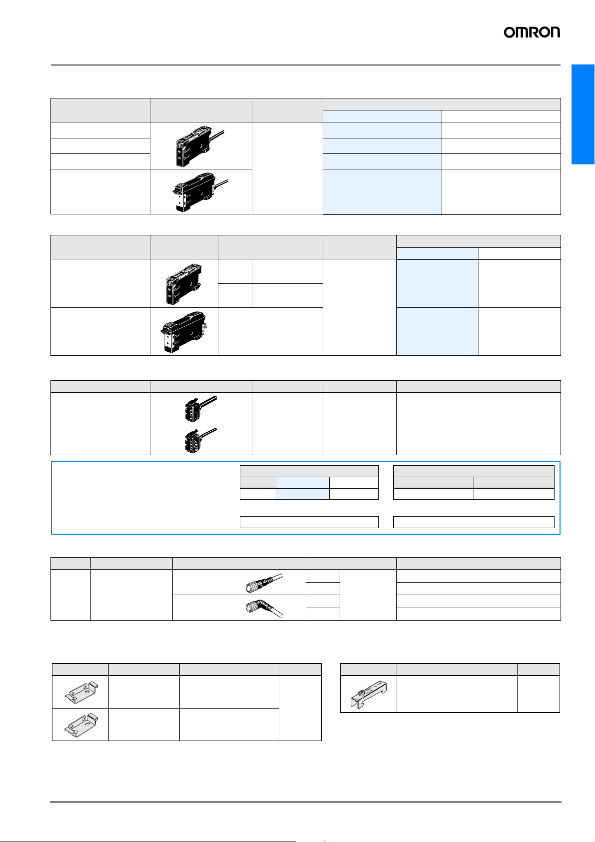
Ordering Information
Amplifier Units
Pre-wired
Item Shape Control output
Standard models
High-speed detection
Mark-detecting models
ON/OFF output
Model
NPN output PNP output
E3X-NA11 E3X-NA41
E3X-NA11F E3X-NA41F
E3X-NAG11 E3X-NAG41
E3X-NA
Water-resistant models
E3X-NA11V E3X-NA41V
Connector type
Item Shape
Standard models
Water-resistant models
(M8 Connector)
Applicable Connector
(order separately)
Master E3X-CN11
Slave E3X-CN12
XS3F-M421-40#-A
XS3F-M422-40#-A
Control output
ON/OFF output
NPN output PNP output
E3X-NA6 E3X-NA8
E3X-NA14V E3X-NA44V
Model
Amplifier Units Connectors (Order Separately) Note: Stickers for Connectors are included as accessories.
Item Shape Cable length No. of conductors Model
Master connector
2 m
Slave connector 1 E3X-CN12
Precautions for ordering the connector type
Refer to the following tables when placing an order. Basically, Amplifier Units and connectors are sold separately.
Please place an order after referring to the combination giv-
Type NPN PNP
Standard
When Using 5 Amplifier Units
Amplifier Units Applicable Connector (order separately)
E3X-NA6
Amplifier Units (5 Units)
3 E3X-CN11
Master connector Slave connector
+
E3X-NA8
E3X-CN11 (3 wires) E3X-CN12 (1 wire)
1 Master Connector + 4 Slave Connectors
+
Sensor I/O Connectors (Order separately)
Size Cable type Shape Cable length Model
M8 Standard cable
Note: Refer to page NB-6 for details.
Straight
L-shaped
2 m
5 m XS3F-M421-405-A
4 conductors
2 m XS3F-M422-402-A
5 m XS3F-M422-405-A
XS3F-M421-402-A
Accessories (Order Separately)
Mounting Brackets
Shape Applicable type Model Quantity
E3X-NA#
E3X-NA#F
E3X-NAG#
E3X-NA#V E39-L148
E39-L143
1
End Plate
Shape Model Quantity
PFP-M
1
A-375E3X-NA
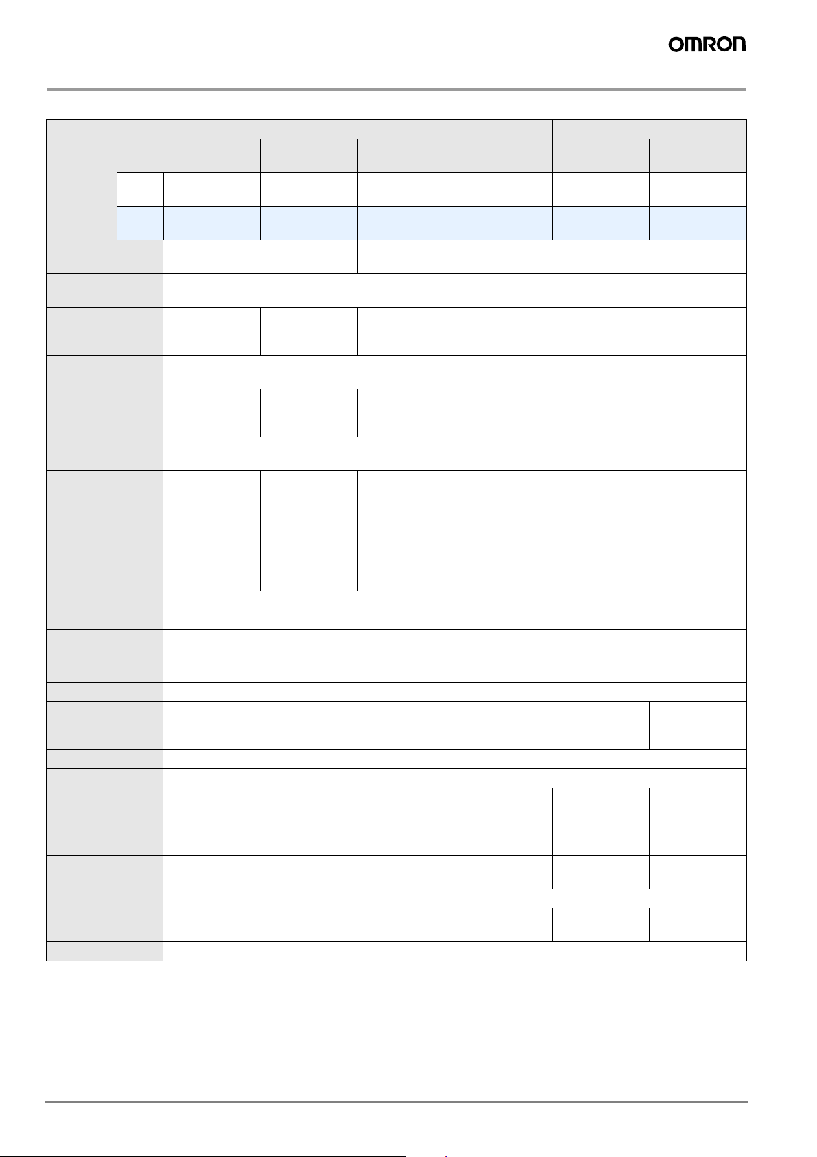
Rating/performance
Amplifier Units
Pre-wired Connector type
Type Standard models
NPN
Model
Item
Light source (wave
length)
Power supply voltage
Current consumption 35 mA max.
Control output
Response time
Sensitivity adjustment
Protective circuits
Timer function OFF-delay timer: 40 ms (fixed)
Ambient illuminance Incandescent lamp: 10,000 lux max. Sunlight: 20,000 lux max.
Ambient temperature
Ambient humidity Operating/Storage: 35% to 85% RH (with no condensation)
Insulation resistance 20 M min. at 500 VDC
Dielectric strength 1,000 VAC at 50/60 Hz for 1 minute
Vibration resistance 10 to 55 Hz with a 1.5 mm double amplitude for 2 hrs each in X, Y and Z directions
Shock resistance Destruction: 500 m/s2 for 3 times each in X, Y, and Z directions
Protective structure IEC 60529 IP50 (with Protective Cover attached)
Connection method Pre-wired models (standard length: 2 m) Connector type
Weight (Packed
state)
Material
Accessories Instruction manual
* If 8 or more Units are installed side-by-side, the response time will be 350 s max.
output
PNP
output
Case PBT (polybutylene terephthalate)
Cover Polycarbonate
E3X-NA11 E3X-NA11F E3X-NAG11 E3X-NA11V E3X-NA6 E3X-NA14V
E3X-NA41 E3X-NA41F E3X-NAG41 E3X-NA41V E3X-NA8 E3X-NA44V
Red LED (680 nm)
12 to 24 VDC ±10%, ripple (p-p): 10% max.
Load current 50 mA (residual voltage 1 V max. each) Open collector output type (depends on the NPN/PNP output format) Light-ON/Dark-ON switch selectable
Operation or reset: 200 s max. *
8-turn endless adjuster (with indicator)
Reverse polarity
protection, output short-circuit
protection, mutual interference
prevention (optically synchronized)
Operating: Groups of 1 to 3 Amplifiers: -25 to +55°C, Groups of 4 to 11 Amplifiers: -25 to +50°C, Groups of 12 to
16 Amplifiers: -25 to +45°C Storage: -30 to +70°C (with no icing and condensation)
Approx. 100 g Approx. 110 g Approx. 55 g 65 g
High-speed de-
tection models
35 mA max. (at
power supply
voltage 24 VDC)
Operating: 20 s
max. Reset: 30 s
max.
Reverse polarity
protection, output short-circuit
protection
Mark-detecting
models
Green LED
(520 nm)
35 mA max.
200 s max. for operation and reset respectively (See note.)
Reverse polarity protection, output short-circuit protection, mutual interference prevention (optically synchronized)
Water-resistant
models
Red LED (680 nm)
IEC 60529 IP66
(with Protective
Cover attached)
Polyethersulfone (PES)
Standard models
IEC 60529 IP50
(with Protective
Cover attached)
Polycarbonate
Water-resistant mod-
els (M8 Connector)
500 VAC at
50/60 Hz for
1 minute
IEC 60529 IP66
(with Protective
Cover attached)
M8 connector
Polyethersulfone (PES)
A-376 Photoelectric Sensors

Amplifier Unit Connectors
Item Model E3X-CN11 E3X-CN12
Rated current
Rated voltage
Contact resistance
2.5 A
50 V
20 m max. (20 mVDC max., 100 mA max.) [By connection with amplifier unit and connection with adjacent con-
nector (except conductor resistance of cable)]
No. of insertions 50 times (By connection with amplifier unit and connection with adjacent connector)
Material
Weight (Packed
state)
Housing PBT (polybutylene terephthalate)
Contacts Phosphor bronze/gold-plated nickel
Approx. 55 g Approx. 25 g
Characteristic data (typical)
Number of Turns of Sensitivity Adjuster
vs. Sensing Distance
E32-T11L E32-D11L
E3X-NA
1.2
1.0
Distance (m)
0.8
0.6
0.4
0.2
0
E3X-NA# (V)
E3X-NA# F
246810
Number of turns
400
300
Distance (mm)
200
100
0
Sensing Distance vs. Hysteresis
E32-T11L E32-D11L
100
80
Hysteresis (mm)
60
40
20
100 200 300 400 500 600 700
0
E3X-NA# (V)
Distance (mm)
20
15
Hysteresis (mm)
10
5
0
E3X-NA# (V)
E3X-NA# F
246810
Number of turns
E3X-NA# (V)
50 100 150 200
Distance (mm)
A-377E3X-NA

Output Circuit Diagram
NPN output
Model
E3X-NA11
E3X-NA6
E3X-NAG11
E3X-NA11F
E3X-NA11V
E3X-NA14V
PNP output
Model
E3X-NA41
E3X-NA8
E3X-NAG41
E3X-NA41F
E3X-NA41V
E3X-NA44V
Operating status of
output transistor
Light ON
Dark ON
Operating status of
output transistor
Light ON
Dark ON
Interrupted
Operation
indicator
(orange)
Output
transistor
Load
(Relay)
Interrupted
Operation
indicator
(orange)
Output
transistor
Load
(Relay)
Interrupted
Operation
indicator
(orange)
Output
transistor
Load
(Relay)
Interrupted
Operation
indicator
(orange)
Output
transistor
Load
(Relay)
Timing chart
Incident
ON
OFF
ON
OFF
Operate
Reset
(Between brown and black)
Incident
ON
OFF
ON
OFF
Operate
Reset
(Between brown and black)
T
T
Timing chart
Incident
ON
OFF
ON
OFF
Operate
Reset
(Between brown and black)
Incident
ON
OFF
ON
OFF
Operate
Reset
(Between brown and black)
T
T
Mode selection switch
LON
(LIGHT ON)
DON
(DARK ON)
Mode selection switch
LON
(LIGHT ON)
DON
(DARK ON)
Operation
indicator
(orange)
Operation
indicator
(orange)
Main
circuit
Main
circuit
Note: Pin 2 is open.
Output circuit
Brown
1
Black
4
Blue
3
Load
Control output
M8 Connector Pin Arrangement
2
4
1
3
Note: Pin 2 is open.
Output circuit
Brown
1
Control output
Black
4
Load
3
Blue
M8 Connector Pin Arrangement
2
4
1
3
12 to 24 VDC
12 to 24 VDC
Connectors (Sensor I/O connectors)
Termination No.
2
4
3
1
2
1
3
4
XS3F-M421-402-A
XS3F-M421-405-A
XS3F-M422-402-A
XS3F-M422-405-A
Color of
cable conductors
Brown
White
Blue
Black
Class
Wire, outer
jacket color
Brown A
For DC
White B -
Blue C
Black D Output
Note: Pin 2 is not used.
Connector
pin No.
Application
Power
supply (+V)
Power
supply (0 V)
A-378 Photoelectric Sensors

Nomenclature:
.
Precautions
Amplifier Units
Sensitivity Indicator
8-turn sensitivity adjuster
Operation Mode Selector
Lock Button
Incident level indicators
Operation indicator
Use to switch between Light ON and Dark ON modes
Timer switch
ON: Timer function is ON.
OFF: Timer function is OFF.
Operation
Indicator status
In addition to the operation indicator (orange), E3X-NA has indicators that denote the incident level (4 green and 1 red indicators). Use them for optical axis adjustment and maintenance.
Indicator status (L/ON)
Operation indicator Incident level indicators
Not lit Lit (See note)
Operation in-
dicator (L/ON)
Not lit
Incident level
Approx. 80%
to 90% of operating level
Correct Use
Amplifier Units
Design
Communications Hole
The window provided in the side face of the unit is a communication window for prevention of mutual interference when it
is connected with the other unit. Note that the optional Mobile
Console E3X-MC11 cannot be used. When the incident level
of the sensor is excessive, mutual interference prevention
may not be activated. At that time, make adjustment with the
sensitivity adjuster. When the unit is used with the E3X-DA-N
series, mutual interference prevention is not activated.
Mounting
Connection/removing of amplifier units
(Connection)
1. Install the Amplifier Units one at a time onto the DIN track.
2. Slide the Amplifier Units together, line up the clips, and
press the Amplifier Units together until they click into place.
E3X-NA
Not lit
Not lit or lit
Lit
Lit
Note: The rightmost indicator is turned ON at the "0 incident level".
Approx. 80%
to 90% of operating level
Approx. 90%
to 110% of
operating
level
Approx. 110%
to 120% of
operating
level
Approx. 120%
min. of operating level
Clip
Clip into
place
(Removing)
Slide one unit away from the other and remove them one by
one. (Do not remove the connected units together from the
DIN rail.)
Note: 1 .When the amplifier units are interconnected, the operating ambient
temperature changes depending on the number of connected amplifier units. Check "Ratings/Performance".
2 .Before connecting or removing the units, always switch power off.
Operating Environment
Ambient Conditions
Always remove dust, dirt, etc. from the optical communication
window, which may disable communication.
Miscellaneous
Protective Cover
Be sure to set the Protective Cover before use.
A-379E3X-NA

Amplifier Unit Connectors
Installation
Installation Connectors
1. Insert the Master or Slave Connector into the Amplifier Unit
until it clicks into place.
Insert
2. Join Amplifier Units together as required after all the Master
and Slave Connectors have been inserted.
3. Apply the supplied seal to the non-connection surface of the
master/slave connector.
Mounting End Plate (PFP-M)
Depending on the installation type, an Amplifier Unit may
move during operation. In this case, use an End Plate.
Before installing an End Plate, remove the clip from the master Amplifier Unit using a nipper or similar tool.
The sensor bottom is also equipped with the clip removing
mechanism.
1. Insert the clip to be removed into the slit underneath the clip
on another Amplifier Unit.
Sticker
Note: Apply the seal to the grooved side.
Sticker
Removing Connectors
1. Slide the slave Amplifier Unit for which the Connector is to
be removed away from the rest of the group.
2. After the Amplifier Unit has been separated, press down on
the lever on the Connector and remove it. (Do not attempt
to remove Connectors without separating them from other
Amplifier Units first.)
Press down
Lever
Remove
2. Remove the clip by rotating the Amplifier Unit.
Rotate
Pull Strengths for Connectors (Including Cables)
E3X-CN11: 30 N max. E3X-CN12: 12 N max.
A-380 Photoelectric Sensors
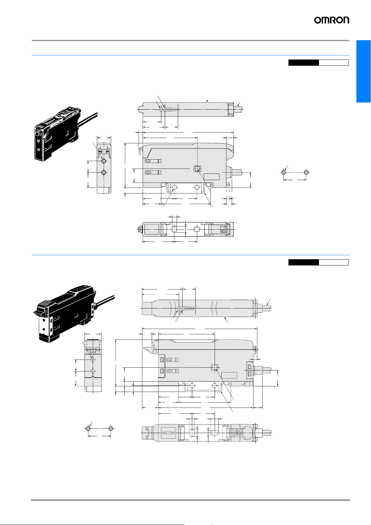
Dimensions (Unit: mm)
P
d
Amplifier Units
re-wire
E3X-NA11
E3X-NA11F
E3X-NA41
E3X-NA41F
E3X-NAG11
E3X-NAG41
Two, 2.4 dia.
8
10.7
CAD file E3X_05
E3X-NA
With Mounting Blanket Attached
Operation indicator
10
31.5
9.9
4.1
Incident level indicators
13.05
15.75
3
13
Two, 3.2 dia. holes Mounting bracket (E39-L143); Sold separately
9.2
38.6
22.4
3.4
22.4 16
64.3
16
34.8
4.4
(A)*1
Holes for optical communications * 2
Stainless steel (SUS304)
4-dia., 3-conductor,
vinyl-insulated round cable
(conductor cross-sectional
area: 0.45 m‡u; insulation
diameter: 1.1 mm)
5.3
10.75
2.4
4
Note: * 1. The mounting bracket can also be used on side A.
* 2. The hole for optical communications is for
preventing mutual interference. There is no
hole for E3X-NA
Mounting Holes
2-M3
16
#F models.
Amplifier Units with cables,
CAD file E3X_10
Water-resistant Models
E3X-NA11V
E3X-NA41V
8
10.7
Mounting Holes
12
33
9.9
3.43.9
2-M3
16
Two, 2.4 dia.
With Mounting Blanket Attached
28.65
25.95
Operation indicator
6.9
4.3
11.5
Incident level indicators
23.9
14.4
23.9
9.2
* 2
81.5
40
16
37
67.2
16
3.4
5.4
3.4
(A)*1
2.8
11.2
Holes for
optical
communications
Mounting bracket (E39-L148); Sold separately
Stainless steel (SUS304)
5.4
Note:*1.The mounting bracket can also be used on side A.
6.6
4-dia., 3-conductor, vinyl-insulated round cable
*2.
(conductor cross-sectional area: 0.45 mm²;
insulation diameter: 1.1 mm)
A-381E3X-NA
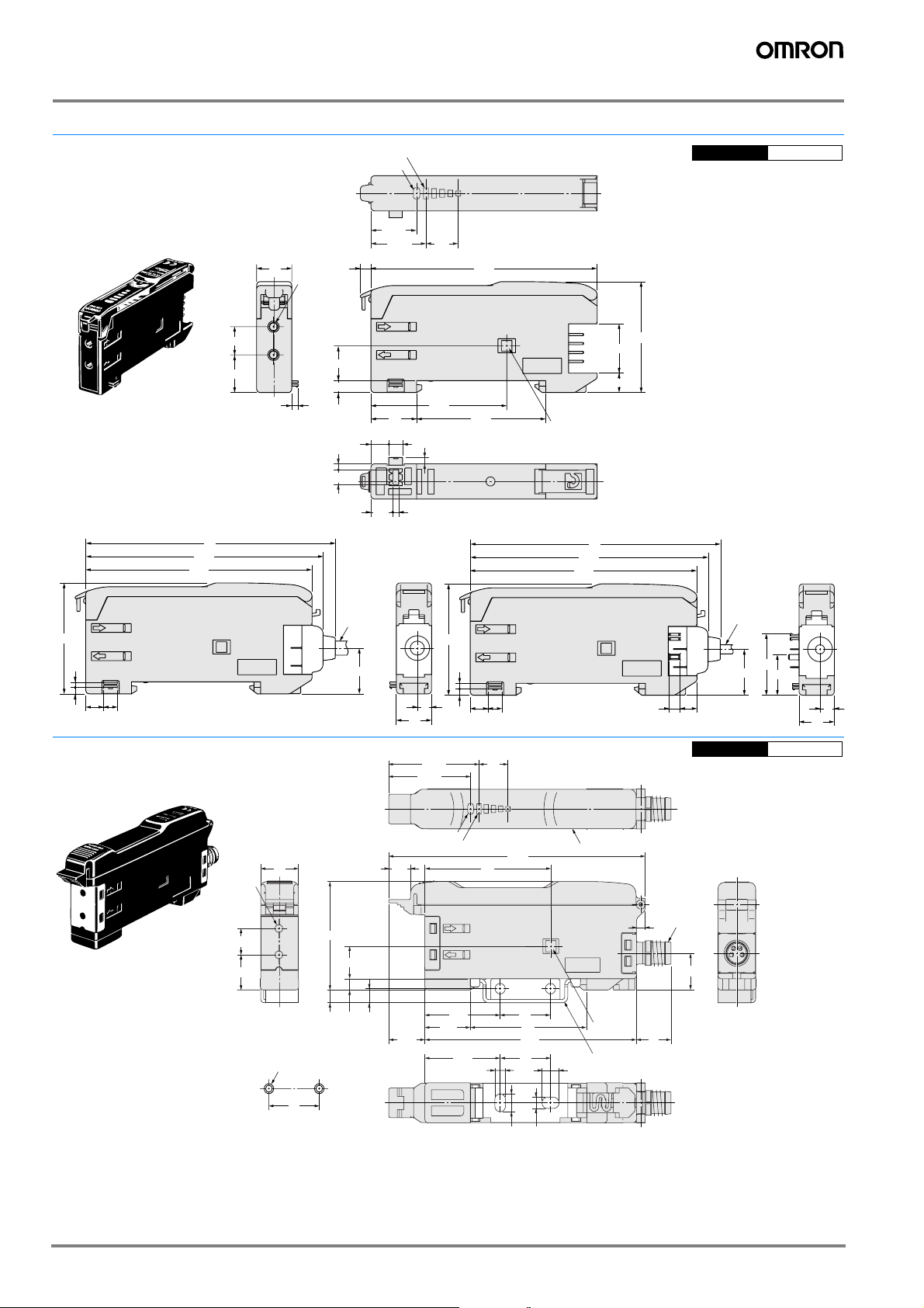
C
onnector type
E3X-NA6
E3X-NA8
10
Operation indicator
Two, 2.4 dia.
Incident level indicators
13.05
15.75
9.2
CAD file E3X_06
64.33
8
1.8
9.9
3.4
1.7
4.2
E3X-CN11:
4.0 dia.
12.95
38.6
31.5
36.7
1.5
1.8
5.1 3.9
13
3.95.1
1.8
6.2
1.7
4
10
With Mounting Blanket Attached
28.65
25.95
9.2
Holes for optical communications
(for preventing mutual interference)
67.5
64.3
10.7
Dimensions with Master Connector Connected Dimensions with Slave Connector Connected
71
67.5
64.3
31.5
1.5
1.8
5.1 3.9
Amplifier Units M8 Connectors,
Water-resistant Models
E3X-NA14V
Note:*1.The mounting bracket
can also be used on side A.
31.5
14
5.5
71
E3X-CN12: 2.6 dia.
17.45
12.95
11.55
3
4.8
4
10
CAD file E3X_11
E3X-NA44V
Two, 2.4 dia.
8
10.7
12
Mounting Holes
2-M3
16
Operation indicator
6.9
33
9.9
3.43.9
4.3
11.5
Incident level indicators
40
23.9
14.4
23.9
81.5
16
37
67.2
16
3.4
5.4
3.4
(A)*1
M8
2.8
11.2
Holes for
optical
communications
Mounting bracket (E39-L148); Sold separately
Stainless steel (SUS304)
5.4
11
A-382 Photoelectric Sensors

Amplifier Unit Connectors
Mast
er connector
E3X-CN11
10
2.9
Slave connector
E3X-CN12
10
2.9
Accessories (Order Separately)
Mounting Brackets
A-216
+
50
2,000
6
2.6
14.4
6
0.8
6
2.6
14.4
6
0.8
3
10.7
6.8
4
8.4
15.1
10.7
6.8
4
8.4
15.1
0
4-dia., 3-conductor, vinyl-insulated
round cable (conductor cross-sectional
area: 0.45 mm
4-dia., 3-conductor,vinyl-insulated
round cable (conductor cross-sectional
area: 0.45 mm
²; insulation diameter: 1.1 mm)
+
50
2,000
0
²; insulation diameter: 1.1 mm)
2.6 dia.
4 dia.
30± 2
+
5
50
0
30
± 2 10± 2
+
5
50
0
E3X-NA
10
± 2
A-383E3X-NA

ALL DIMENSIONS SHOWN ARE IN MILLIMETERS.
To convert millimeters into inches, multiply by 0.03937. To convert grams into ounces, multiply by 0.03527.
Cat. No. E23E-EN-Cat04-01
In the interest of product improvement, specifications are subject to change without notice.
A-384 Photoelectric Sensors
 Loading...