

Page 1
©
OMRON Corporation 2005 All Rights Reserved.
Instruction Sheet
Thank you for selecting an OMRON product.This sheet primarily describes precautions
required in installing and operating the product.
• The specialist who has the knowledge of electricity must treat.
• Please often read this manual, and use it correctly after it understands enough.
• Please keep this manual importantly to refer at any time.
Digital Fiber Sensor
Please observe the following precautions for safe use of the product.
1)Do not use the Amplifier Unit in environments subject to flammable or explosive gases.
2)Do not use the Amplifier Unit in environments subject to exposure to water, oil, chemicals, etc.
3)Do not attempt to disassemble, repair, or modify the Amplifier Unit in any way.
4)Do not apply voltages or currents that exceed the rated ranges.
5)Wire the Amplifier Unit correctly, e.g., do not reverse the polarity of the power supply.
6)Connect the load correctly.
7)Do not short both ends of the load.
8)Do not use the Amplifier Unit if the case is damaged.
9)When disposing of the Amplifier Unit, treat it as industrial waste.
*1: When using individually or as a master, obtain the E3X-CN21 Master Connector (4-conductor), and when using as a slave, obtain
the E3X-CN22 Slave Connector (2-conductor). Either Connector can be used.
*2: Communications are disabled if SHS is selected for the detection mode, and the communications functions for mutual interference
prevention and the Mobile Console will not function.
*3: Mutual interference prevention can be used for only up to 6 Units if power tuning is enabled.
③Operation indicator for channel 2
⑥Channel selector
Power supply
connector
Protector seal
1
2
UP
SET RUN 1 2
DOWN MODE
⑧Lock button
①Operation indicator
for channel 1
②Main display (red)
④Sub-display (green)
⑦Operation keys
⑤SET/RUN switch
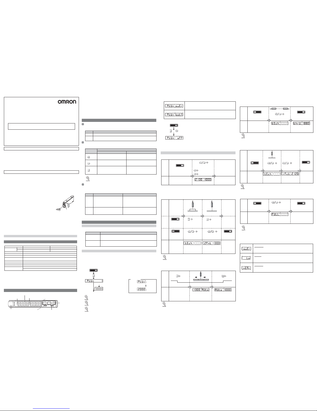
Setting the Mode
Key Operations
Reading Displays
SET
Mode
Main display (red) Sub-display (green)
RUN
(See
note.)
SET Select to set detection conditions, to teach the threshold value, etc.
Mode Description
RUN Select for actual detection operation or to set the following: Manual adjustment of threshold
value, teaching power adjustment, zero reset, or key lock.
UP key
Setting
Setting
RUN
mode
SET
mode
Display
Display
Increases the threshold value. Depends on the setting.
• Executes teaching.
• Changes the setting forward.
Decreases the threshold value.
Switches the function to be set on the
display.
DOWN key
MODE key
Key
Function
RUN mode SET mode
LON (light-ON)
(default)
Selection Description
DON (dark-ON)
RUNSET
Switch to RUN mode.
Tuning completed and previous display returns.
Main Display
Press the MODE key for at least 3 seconds.
Power tuning target value
PTUN
During power tuning
Progress bar
PTUN
①Lit when the output for channel 1 is ON.
②Displays the incident light level or the function name.
③Lit when the output for channel 2 is ON.
④Displays the incident light level, additional information for detection, or the function
setting for channel 2.
⑤Used to switch the mode.
⑥Used to select the channel to display or set.
⑦Used to change the display, set functions, etc.
⑧Used to connect and disconnect the Fiber Unit.
If power is tuned when SHS is selected for the detection method, the power
will be set to the minimum value.
Depends on the setting.
• Executes teaching.
• Changes the setting in reverse.
Depends on the MODE key setting.
• Teaching
• Executes power tuning.
• Executes a zero reset.
Time to Press Keys
If a specific time for pressing a key is not given in a procedure, press the key for approximately 1 second.
For example, if the procedure says ìpress the UP key,î then press the UP key for approximately 1 second
and then release it.
Displays the incident light level, function name,
or other information depending on the key
operation.
For the default setting,the current incident light
level for channel 1 will be displayed
Displays threshold value or the setting of the function
displayed on the main display depending on the key
operation.
For the default setting,the current incident light level for
channel 2 will be displayed
The output will turn ON when the incident light level is above the threshold.
The output will turn ON when the incident light level is below the threshold.
Confirm that the MODE key setting is PTUN (power tuning) in advance. PTUN is the default setting. Refer
to 5.DetailedSettings.
Select the channel for power tuning with the channel selector.
A progress bar will appear on the
sub-display one digit at a time.
(Release the MODE key when the
progress bar appears.)
Display
alternates at
a fixed
interval.
Over Error
The incident light level is too low for the power tuning target value.
The power can be increased up to approximately 5 times the incident
light level without power tuning.
PTUN OVER
Switch to RUN mode
Bottom Error
The incident light level is too high for the power tuning target value.
The power can be decreased down to approximately 1/25th the incident light
level without power tuning.
PTUN BOTM
PTUN OFF
RUNSET
Hold down the MODE key and press the DOWN key for at least 3 seconds.
Note: Press the DOWN key right after pressing the MODE key.
The sub-display will flash twice and power tuning will be cleared.
Flashes twice
Flashes twice
+
■ Clearing Method
1636622-0A
Precautions for Safe Use
Precautions for Correct Use
2. Nomenclature
The mode is set using the SET/RUN switch. Set this switch according to the operation to be
performed.
The operation keys are used to switch the displays and set detection conditions. The functions
of the keys depend on the current mode.
The information displayed on the main display and sub-display depends on the current mode.
For the default settings, the RUN mode displays will appear when the power supply is turned
ON for the first time.
Note: The information that appears on the displays can be set using the display switch
function. Refer to 5.DetailedSettings.
Select either light-ON or dark-ON operation.
Set as the operation mode in SET mode. Refer to
5.DetailedSettings.
Power tuning can be used to adjust the incident light level that is currently being received to the power
tuning target value (default: 2,000). Before tuning ON the power, always secure the detection object and
Head and be sure that the incident light level is stable.
■ Setting Method
The power tuning target value can be changed. Refer to 5.DetailedSettings.
Switch to RUN mode.
Switch to RUN
mode.
Press the MODE key
for at least 3 seconds.
The sub-display will
flash twice.
The threshold value
that was set will flash
twice.
Press the UP or
DOWN key.
Press the UP or
DOWN key.
Press the MODE key
for at least 3 seconds.
3 seconds. 3 seconds.
Switch to RUN
mode.
Position a workpiece. Remove a workpiece.
Increases the
threshold value
Decreases the
threshold value
RUNSET
Threshold
value
Threshold
value
Light level
Workpiece
1)Manually Setting
2) Teaching
①Teaching With and Without a Workpiece
Teaching can be performed twice, once with and once without a workpiece, and the value
between the two measured values is set as the threshold. RUN mode and SET mode – each
mode can be set up.
PTUN is the default setting. Refer to 5.DetailedSettings.
TECH
ー
2PNT
Adjust the threshold value with
the UP and DOWN keys.
The information set for the
display switch setting will
return approximately 5
seconds
after the threshold is changed.
RUNSET
RUNSET
Switch to RUN
mode.
RUNSET
Confirming the Package Contents
• Amplifier Unit: 1 • Instruction Sheet (this sheet): 1
1. Ratings and Specifications
3. Basic Operating Information
4. Basic Settings
1. Setting the Operation Mode
2. Adjusting the Power (as Required)
3. Setting Thresholds
Setting
Display
AUTO Threshold
value
AUTOLight level
②Automatic-teaching(It sets up at move work.)
While continuing pushing a key, the middle of the detected maximum and the minimum
value can be set up as a threshold. PTUN is the default setting. Refer to 5.DetailedSettings.
Pushing the MODE key
during 3 seconds or more
It is displayed on a sub
digital value as AUTO, and
the sampling of right level is
effective.
Threshold value will flush twice.
Setting
Display
Switch to RUN mode.
Remove a workpiece
Press the UP or DOWN key.
The sub-display will flash
twice.
The threshold value that was
set will flash twice.
RUNSET
Switch to RUN mode.
RUNSET
③Teaching for Through-beam Sensor Heads
Teaching for a Through-beam Sensor Head is performed without a workpiece. A value
about 6% less than the incident light level with no workpiece is set as the threshold value.
This method is ideal to stably detect very small differences in light level.
TECH ー THRU Threshold
value
If the output setting is set to 1-2 (differential operation), the differential value
when teaching is performed is used as the threshold setting for channel 2.
(Same as for Teaching for Reflective Sensor Heads.)
Setting
Display
Remove a workpiece
3 seconds
Switch to RUN mode.
RUNSET
Switch to RUN
mode.
RUNSET
TECH
ー
RFCT
Threshold
value
④ Teaching for Reflective Sensor Heads
Teaching for a Reflective Sensor Head is performed without a workpiece (i.e., for the
background). A value about 6% greater than the incident light level is set as the threshold
value. This method is ideal to stably detect very small differences in light level.
Press the UP or
DOWN key .
Press the UP or DOWN
key for at least 3 seconds.
The sub-display will flash
twice.
The threshold value that
was set will flash twice.
If the output setting is set to 1-2 (differential operation), the differential value
when teaching is performed is used as the threshold setting for channel 2.
(Same as for Teaching for Through-beam Sensor Heads.)
Setting
Display
3 seconds
Switch to RUN mode.
RUNSET
Switch to RUN mode.
RUNSET
Threshold
value
FULL
⑤ Setting the Threshold at the Maximum Sensitivity
The threshold can be set at the maximum sensitivity. This is convenient when using
the longest sensing distance.
Press the UP or DOWN
key for at least 3 seconds.
The threshold value that was
set will flash twice.
It does not matter whether or not there is a workpiece.
The value that is set will depend on the detection method and power adjustment
settings.
If the output setting is set to 1-2 (differential operation), no threshold setting is
possible for channel 2.
• Teaching Error
OVER
flash twice.
flash twice.
flash twice.
NEAR
LO
After performing teaching, when the following is displayed on sub digital display, the error has occurred.
However, the threshold might not be able to be detected correctly though is set within the possible range.
Over error
Low error
Near error
Light level is too large. Do one of the following and then repeat the
operation.
• Adjust the Head to decrease the incident light level.
• Execute power tuning.
Light level is too small. Do one of the following and then repeat the
operation.
• Adjust the Head to increase the incident light level.
• Execute power tuning.
The difference of incident light level is too small. Do one of the
following and then repeat the operation.
• Adjust the Head to increase the difference between the two
incidentlight levels .
Power tuning will be cleared whenever the detection method is changed from
STND, HRES, or SHS.
E3X-MDA Series
If the output setting is set to 1-2 (differential operation), the value between the two
differential values when teaching is performed is used as the threshold setting.
If the output setting is set to 1-2 (differential operation), the value between
the
detected maximum and the minimum differential values when teaching is
performed is used as the threshold setting.
Please observe the following precautions to prevent failure to operate, malfunction, or undesiable effects on
product performance.
1)The optical fibers are made out of methacrylic resin. Do not use them in atmospheres where organic solvents
are present.
2)Wire the Amplifier Unit separately from power supply or high-voltage lines. If the Amplifier Unit wiring is wired
together with or placed in the same duct as high-power lines, inductive noise may cause operating errors or
damage the Amplifier Unit.
3) Do not extend the cable to more than 100 m, and use a wire size of 0.3 mm
2
or larger for the extension cable.
4)The Amplifier Unit is ready to operate 200 ms after the power supply is turned ON. If the Amplifier Unit and load
are connected to power supplies separately, turn ON the power supply to the Amplifier Unit first.
5)Always keep the protective cover in place when using the Amplifier Unit.
6)Connector Short-circuit Protection (for Amplifier Units with Connectors)
To prevent electric shock or short-circuits, attach the protector seals provided
with E3X-CN-series Connectors to the sides of power supply connectors
that are not being used.
7)Always turn OFF the power supply before connecting, separating, or
adding Amplifier Units.
8)If the data is not written to the EEPROM correctly due to a power failure or
static-electric noise, initialize the settings using the keys on the Amplifier
Unit.
9) Using a Mobile Console
Use the E3X-MC11-SV2 Mobile Console for the E3X-DA-S series Amplifier
Units. However, there is a function which cannot be used in part. Other
Mobile Consoles, such as the E3X-MC11, cannot be used.
10) Optical communications are not possible with an E3X-DA-N Amplifier Unit.
11) Depending on the application environment, time may be required for the incident light level to stabilize after
the power supply is turned ON.
12) Do not use thinners, benzine, acetone, or kerosene for cleaning the Amplifier Unit.
13) Do not pull or apply excessive pressure or force (exceeding 9.8 N・m) on the Fiber Unit when it is mounted to
the Amplifier Unit.
14) Output pulses may occur when the power is interrupted and so turn OFF the power to the load or load line
before turning OFF the power to the Sensor.
•
Power tuning Errors
An error has occurred if one of the following displays appears after the progress bar is displayed.
Prewired Separate connector*
1
E3X-MDA11 E3X-MDA6
E3X-MDA41 E3X-MDA8
12 to 24 VDC ±10%, ripple (p-p) 10% max.
Red LED
NPN
PNP
1,080 mW max. (45 mA max. at 24 V)
Open collector (26.4 VDC max.);
load current: 50 mA max.; residual voltage: 1 V max.
OFF, OFF-delay, ON-delay, or one-shot
1 ms to 5 s
Supported
Supported (optical communications sync method)*2
9 Sensors (18 channels)*
3
Model number
Light emitting element
Supply voltage
Power consumption
Mutual interference
prevention
Control output
Timer
Timer time
Power tuning
Connection method
Page 2
RUNSET
Teaching (Light level/Threshold display)
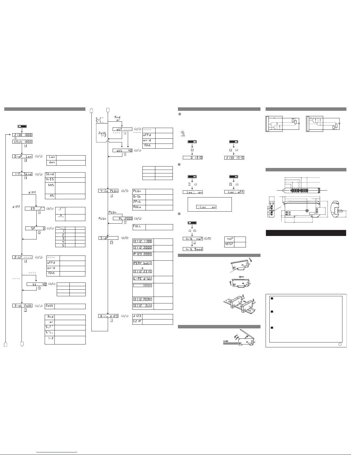
0. Operation
Mode
Light-ON
LON
DON
Dark-ON
1-ms increments1 to 20 ms
5-ms increments
20 to 200 ms
100-ms increments200 ms to 1 s
1-s increments1 to 5 s
Single edge
Either the rising or falling
edge is detected.
Double edge
Both the rising and falling
edge are detected.
Timer disabled.
----
OFF D
OFF-delay timer
ON-D
ON-delay timer
1SHT
One-shot timer
250 μs 500 μs
500 μs 1 ms
1 ms 2 ms
10 ms 20 ms
100 ms 200 ms
Single edge
This setting depends on the setting for
the differential edge selection.
Switch to SET mode.
Setting range: 1 to 5,000
Double edge
Not
Not
1. Detection
Method
Differential
Edge Selection
Differential
Response Time
Set separately for each channel.
Set separately for each channel.
2. Timer
Timer Time
Not
Note: Refer to 4. Basic Settings for teaching methods.
The following functions can be set in SET mode. The default settings are shown in the transition boxes
between functions.
All settings except for the operation mode and timer settings are the same for both channels.
*: The values shown for thresholds, incident light levels, percentages, etc., are examples only. Actual
displays may vary.
Normal display
D123
321D
Reversed display
Tunes the power.
Teaching With and Without a
Workpiece
Automatic-teaching
Maximum power
B
PTUN
0RST
FULL
Executes a zero reset.
2PNT
AUTO
Setting range: 100 to 3,900
The function of the MODE key in RUN mode can be selected.
4. MODE Key
Setting
B
A
If the output setting is set to 1-2 (differential operation),
channel 2 cannot be zeroed.
The incident light level displayed on the main display can be zeroed. The threshold displayed in the
sub-display is shifted by an amount corresponding to the amount the incident light level was
changed.
Confirm that the MODE key setting is 0RST (zero reset) in advance. PTUN (power tuning) is the
default setting. Refer to 5. Detailed Settings.
Select the channel for zeroing with the channel selector.
■ Setting Method ■ Clearing Method
All key operations can be disabled to help prevent key operating errors.
Only the operation keys are disabled. The switches and selectors will still function.
■ Setting Method ■ Clearing Method
This procedure can be used to return all the settings to the original default values.
■ Setting Method
■ Mounting Units
Catch the hook on the Fiber Unit connector end of the
Unit on the DIN Track and then press down on the
other end of the Unit until it locks into place.
Always attach the Fiber Unit connector end first.
If the incorrect end is attached first, the mounting
strength will be reduced.
■ Removing Units
Press the Unit in the direction indicated by "1"
and then lift up on the Fiber Unit connector end
of the Unit in the direction indicated by "2."
■ Joining Amplifier Units (for Units with Connectors)
Up to 16 Units can be joined.
1. Mount the Amplifier Units one at a time onto the
DIN Track.
2. Slide the Amplifier Units together and press the
Amplifier Units together until they click into place.
Secure the Units with an End Plate (PFP-M) if there is a
possibility of the Amplifier Units moving, e.g., due to vibration.
Reverse the above procedure to separate and remove the
Units. Do not attempt to remove Amplifier Units from the
DIN Track without separating them first.
1. Open the protective cover
2. Press up the lock button.
3. Insert the fibers all the way to the back
of the connector insertion opening.
4. Return the lock button to its original
position to secure the fibers.
Zeroing the Main Display
Switch to RUN mode.
Switch to RUN mode.
Switch to RUN mode. Switch to RUN mode.
The display will be zeroed,
i.e., the incident light level
will be displayed as 0.
RUNSET RUNSET
RUNSET
Press the MODE key for
at least 3 seconds.
The display of the incident light
level will stop changing.
Initializing Settings
RUNSET
RUNSET
Initialization has been completed.
Key Lock
Settings not
initialized.
NO?
YES?
Settings
initialized.
Switch to SET mode.
+
+
+
Press the UP or DOWN key for at least 3 seconds.
+
Channel 1 light level Channel 2 light level
Channel 1 light level Channel 2 light level
LOC ON
LOC OFF
INIT Press the MODE key at the
NO? or YES? display.
INIT GOOD
Hold down the MODE key and
press the DOWN key for at
least 3 seconds.
Press the DOWN key right
after pressing the MODE key.
The zero reset
function will be
cleared.
Hold down the MODE key and
press the UP key for at least 3
seconds. Press the UP key right
after pressing the MODE key.
The sub-display will flash
twice and key input will be
disabled.
Hold down the MODE key
and press the UP key for at
least 3 seconds. Press the
UP key right after pressing
the MODE key.
The sub-display will
flash twice and key
input will be enabled.
1
1
2
DIN Track
1
2
DIN Track
Hook on the Fiber Unit connector end
1
2
4
3
If a key is pressed while key operations are locked,
"LOC ON" will flash twice on the display to indicate
that key operations have been disabled.
Reverse the above procedure to disconnect the Fiber Unit.
3. Output
Setting
Light level PEAK
Light level Channel
The incident light level
and the channel.
Light level Threshold
The information displayed in RUN mode can be selected.
When going to SET mode, this setting will be ignored and
the incident light level and threshold value will be displayed.
5. Display
Switch
% light level
Threshold
L-PE D-BT
Detection status
Alternates at
a fixed interval
PEAK BOTM
Peak level
Bottom level
Standard mode
Response Time:1ms
STND
HRES
High-resolution mode:
Response Time:4ms
SHS
Super-high-speed mode
Response time: 130
μ
s
(200 μs when AND, OR, leading edge
sync,falling edge sync, or differ-ential
output is enabled)
HS
High-speed mode
Response time:450μs
A
The current incident
light level and the peak
incident light level.
The incident light level
and threshold value
The incident light level as
a percentage of the
threshold value and the
threshold value.
The peak incident level
and bottom incident level
of fixed time(2s).
The incidient light peak
level and no incident
light bottom level.
Analog bar display. The
current detection status
is displayed as an
analog bar. The bar will
lengthen from the right
6. Display
Orientation
5. Detailed Settings 6. Convenient Functions 9. I/O Circuits
10. Dimensions
7. Installing the Amplifier Unit
8. Connecting the Fiber Unit
The operation of channel 2 output can be selected.
The settings described below apply to channel 2 output.
(Channel 1 output is not affected.)
Output for each channel
2OUT
And
Output when the output is ON for both
channels 1 and 2.
or
Output when the output is ON for
either channel 1 or channel 2.
1-2
Rising edge sync. Output if channel 1 is ON when
channel 2 changes from OFF to ON.
Falling edge sync. Output if channel 1 is ON when
channel 2 changes from ON to OFF.
Operates according to the difference
between channels (channel 1 - channel 2).
The difference is used for both threshold
and output judgement execution.
1-ms increments1 to 20 ms
5-ms increments20 to 200 ms
100-ms increments200 ms to 1 s
1-s increments1 to 5 s
Timer disabled
----
OFFD
OFF delay timer
ON-D
ON delay timer
1SHT
One-shot timer
Setting range: 1 to 5,000
Not
The timer for the output of either AND or OR
can be set, depending on which is selected.
Timer time
Timer
Note 1: When rising edge sync or falling edge sync is
selected, the one-shot timer is automatically set,
i.e., the timer function cannot be selected.
2: Set the timer for channel 2 output or differential
output (1-2) using the normal timer setting (2-tF)
for channel 2.
Internal circuits
Load
Load
12 to
24 VDC
Brown
Channel
1 output
Blue
Internal circuits
Load
Load
12 to
24 VDC
Brown
Black
Orange
Blue
Channel
2 output
Black
Orange
■ NPN Models ■ PNP Models
Channel
2 output
Channel
1 output
Channel 1 light level Channel 2 light level
The incident light levels
for channels 1 and 2.
Adisplayischangedinfixedtime.
LOC ON
12.50
11.703.9×3=
32.80
29.80
11.703.9×3=
15.10
12.15
14
36.70
3.40
70
8.10
18.70
32
4.30
9.90
44.30
4.50
7
4.50
5.65
10
(Prewired Models)
Four, 2.40 dia.
OMRON Corporation
Suitability for Use
THE PRODUCTS CONTAINED IN THIS SHEET ARE NOT SAFETY RATED.
THEY ARE NOT DESIGNED OR RATED FOR ENSURING SAFETY OF
PERSONS, AND SHOULD NOT BE RELIED UPON AS A SAFETY
COMPONENT OR PROTECTIVE DEVICE FOR SUCH PURPOSES.
Please refer to separate catalogs for OMRON's safety rated products.
OMRON shall not be responsible for conformity with any standards, codes, or
regulations that apply to the combination of the products in the customer's
application or use of the product.
Take all necessary steps to determine the suitability of the product for the
systems, machines, and equipment with which it will be used.
Know and observe all prohibitions of use applicable to this product.
NEVER USE THE PRODUCTS FOR AN APPLICATION INVOLVING
SERIOUS RISK TO LIFE OR PROPERTY WITHOUT ENSURING THAT THE
SYSTEM AS A WHOLE HAS BEEN DESIGNED TO ADDRESS THE RISKS,
AND THAT THE OMRON PRODUCT IS PROPERLY RATED AND
INSTALLED FOR THE INTENDED USE WITHIN THE OVERALL
EQUIPMENT OR SYSTEM.
See also Product catalog for Warranty and Limitation of Liability.
EUROPE
OMRON EUROPE B.V. Sensor Business Unit
Carl-Benz Str.4, D-71154 Nufringen Germany
Phone:49-7032-811-0 Fax: 49-7032-811-199
NORTH AMERICA
OMRON ELECTRONICS LLC
One Commerce Drive Schaumburg,IL 60173-5302 U.S.A
Phone:1-847-843-7900 Telephone Consultation
1-800-55-OMRON Fax : 1-847-843-7787
ASIA-PACIFIC
OMRON ASIA PACIFIC PTE LTD
83 Clemenceau Avenue,#11-01 UE Square,Singapore 239920
Phone : 65-6-835-3011 /Fax :65-6-835-2711
n
(Unit: mm)
 Loading...