

Page 1
-1-
-2-
Incident light level setting: The larger incident level of the Step 1 and 2 values is
adjusted to the power tuning level.
Threshold setting: Set to the middle between the Step 1 and 2 incident light levels.
©
OMRON Corporation 2011 All Rights Reserved.
Smart Fiber Sensor
E3X-HD
PRECAUTIONS ON SAFETY
Meanings of Signal Words
Warning Indications
PRECAUTIONS FOR SAFE USE
PRECAUTIONS FOR CORRECT USE
Checking the Package Content
INSTRUCTION SHEET
PRECAUTIONS
Indicates a potentially hazardous situation which, if not avoided,
may result in minor or moderate injury or in property damage.
• Amplifier Unit: 1 • Instruction Sheet (this sheet): 1 (Japanese, English and Chinese)
Do not use the product with voltage in excess of the rated voltage.
Excess voltage may result in malfunction or fire.
Never use the product with an AC power supply. Otherwise,
explosion may result.
■
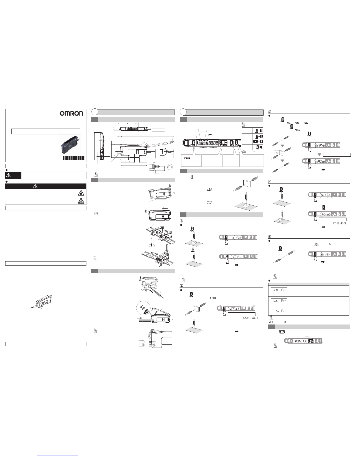
Mounting on DIN Track
Detect for Workpiece Presence/Absence
Detect for Workpiece Presence/Absence
Let the hook on the Amplifier Unit's Fiber Unit
connection side catch the track and push the
unit until it clicks.
■
Removing from DIN Track
Push the unit in the direction 1.
2-point Tuning
Maximum Sensitivity Tuning
■
Mounting Amplier Units in Group
(Connector Type Models)
■
Use Fiber Cutter
Insert a Fiber Unit into a fiber cutter hole.
Press down the blade at a single
stroke to cut the Fiber Unit.
Fiber Cutter E39-F4
(Provided with
the Fiber Unit)
Thin-diameter Fiber
Attachment: E39-F9
Thin-diameter
Fiber Unit Hole x 2
Protective Cover
Fiber Unit
Standard Fiber Unit
Hole (dia. 2.2 mm) x 3
■
Mount Fiber Unit
Open the protective cover.
Raise the lock lever.
Insert the Fiber Unit in the fiber
unit hole to the bottom.
Return the lock lever to the original
position and fix the Fiber Unit.
Press button with a workpiece in the detection area.
Press button again without a workpiece in the detection area.
Through-beam: Workpiece is present
Reective: Workpiece is absent
Press button.
1.
Settings
2
Installation
1
DIN Track
Tighten the screw while pressing the End Plate.
Fiber Unit Connection Side Hook
1
2
Mount the Amplifier Units one at a time onto the
DIN track and push them until they click.
2
1
3
Single Core
Multi Core
1pnt
2pnt
1.
1.
1.
1.
1.
2.
3.
4.
2.
3.
Slide the Amplier Units in the direction 2.
2.
1.
2.
Workpiece
[L/D Indicator]
Displays
Light ON/Dark O setting.
[OUT Indicator]
Turns ON when Output is
ON.
Green Digital Display
Red Digital Display
[DPC Indicator]
[ST Indicator]
Turns ON when Smart Tuning is in progress.
Threshold Level
Incident Light
Level
Minute Threshold
Adjustment
The green digital value changes.
[UP/DOWN]Button
Mode Change
Switches between SET
mode and RUN mode by
a long press (3 seconds
or longer) of the key.
[
MODE]Button
Output Switch
[
L/D]Button
A single press switches between
Light ON/Dark ON. [L/D] Indicator
changes.
A single press each for setting
with/without a workpiece.
[ST Indicator] turns ON.
Sensitivity Setting
[ ]
Button
Workpiece
Workpiece
Protective Label
Power Supply Connecting Terminal
Setting is Completed
Setting is Completed
When mounting a coaxial reflective
Fiber Unit, insert the single-core
Fiber Unit to the upper hole (Emitter
side) and the multi-core Fiber Unit to
the lower hole (Receiver side).
1-3
Mounting Fiber Unit
2-1
Setting and Display Overview
2-2
Switching Control Output
Smart Tuning [Easy Sensitivity Setting]
2-3
1-1
Dimensions
1-2
Mounting the Amplier Unit
L/D
1.
Hold button for 3 seconds or longer with/without workpiece as shown below.
Release the button when [ ] is displayed.
The red digital display changes .
Incident light level setting: The incident level in Step 1 is adjusted to "0".
Threshold setting: The value is set to approx. 7% of the incident light level of 1.
If the incident light level of 1 is smaller during long distance
detection, the minimum value by which an output is correctly
turned ON will be set.
2
4
Lock Lever
Lock
Release
Lift it up in the direction 2.
2.
Hold for 3 seconds or longer
Setting Reset
Key Lock
Zero Reset
Step 1 and Step 2 can be reversed.
Turns ON when Dynamic Power Control is
effective.
5.1
9
71.8
20.5
33.4
37.9 20.5
37
12.7
13
4.55.7
21.7
5.2
4.2
27.1
170°
(Max.)
146.9 (Max. with the protective cover open)
104.7(Max. with the protective cover open)
<Wire-saving Connector Model>
Unit: mm
<Pre-wired Model>
With an thin-diameter ber
attachment (E39-F9)
Blue: 0 V
Brown: 12 to 24 VDC
Black: Output
10
Use E3X-CN11 (Master connector) for the master
Amplier Unit and E3X-CN12 (Slave connector) for
the slave Amplier Units.
Insert a standard Fiber Unit up to the
position in which it is cut; and
a thin-diameter Fiber Unit to the
bottom of the hole.
Refer to " Convenient
Setting Features".
Dimensions in parentheses () indicates the ones with related components.
Refer to "1-1. Dimensions" or check the side of
the unit for wire color and role indications.
Use End Plates (PFP-M: separately sold) at the both
ends of the grouped Amplifier Units to prevent them
from separating due to vibration or other cause.
4.
Tighten the screw on the End Plates using a driver.
3
4
Up to 16 Amplifier Units can be mounted in a group.
2
1
Power Tuning
When Light
Level is
Saturated
Reective: Set to "Light ON" to turn the
output ON with a workpiece in the detection area.
[L/D Indicator] turns ON.
Through-beam: Set to "Dark ON" to turn the
output ON with a workpiece in the detection area.
[L/D Indicator] turns
ON.
Series
+ : Press both
:
Press both in
sequence
Under environments such as vibration, use an end plate
even with a single amplifier unit.
Thank you for selecting an OMRON product. This sheet
primarily describes precautions
required in installing and operating the product.
• A specialist who has the knowledge of electricity must treat
the product.
• Please read this manual carefully, and use it correctly after
thoroughly understanding the product.
• Please keep this manual properly for future reference
whenever it is necessary.
CAUTION
The following precautions must be observed to ensure safe operation of the Sensor.
• Do not use the Sensor in environments subject to flammable or explosive gases.
• Do not use the Sensor in environments subject to exposure to water, oil, chemicals, etc.
• Do not install the Sensor in environments subject to intense electric field or ferromagnetic field.
• Do not attempt to disassemble, repair, or modify the Sensor Unit in any way.
• Do not apply voltages or currents that exceed the rated ranges.
• Do not use the Sensor in any atmosphere or environment that exceeds the ratings.
• Do not miswire such as the polarity of the power supply.
• Connect the load correctly.
• Do not short both ends of the load.
• Do not use the Sensor if the case is damaged.
• When disposing of the Sensor,treat it as industrial waste.
• Burn injury may occur. The Sensor surface temperature rises depending on application conditions, such as the
ambient temperature and the power supply voltage. Use caution when operating or cleaning the Sensor.
• High-Voltage lines and power lines must be wired separately from this product. Wiring them together or placing
them in the same duct may cause induction, resulting in malfunction or damage.
• When setting the Sensor, be sure to check safety such as by stopping the equipment.
2-2.4 dia.
• Do not install the Sensor in the following locations.
(1) Locations subject to direct sunlight
(2) Locations subject to condensation due to high humidity
(3) Locations subject to corrosive gas
(4) Locations subject to vibration or mechanical shocks exceeding the rated values
• Use an extension cable with a minimum thickness of 0.3 mm2 and less than 100 m long.
• Do not apply the forces on the cord exceeding the following limits:
Pull: 40N; torque: 0.1N·m; pressure: 20N; bending: 3 kg
• The Sensor is ready to operate 200 ms after the power supply is turned ON. If the Sensor and load are
connected to power supplies separately, turn ON the power supply to the Sensor first.
• When using a connector type product, place a protective label (provided with the E3X-CN series
connectors) on the power supply connecting terminals that are not used, to prevent electric shock or short
circuit.
• Output pulses may occur when the power supply is turned OFF. Turn OFF the power supply to the load
or load line first.
• Excessive incident light cannot be sufficiently handled by the mutual interference prevention function
and may cause malfunction. To prevent this, set a higher threshold level.
• Make sure that the power supply is turned OFF before connecting, separating or adding Amplifier Units.
• Do not pull or apply excessive pressure or force (exceeding 9.8N) on the Fiber Unit when it is mounted
on the Amplifier Unit.
• The E3X-MC11-SV2 and E3X-MC11-S Mobile Consoles cannot be used.
• Mutual interference prevention does not function among the E3X-DA-N/SD/NA amplifiers. It functions
among E3X-DA-S/MDA models.
• The E3X-DRT21-S, E3X-CRT and E3X-ECT Communication Units cannot be used.
• Always keep the protective cover in place when using the Amplifier Unit.
• Dor not use thinner, benzine, acetone, and lamp oil for cleaning.
L/D
MODE
UP/DOWN
UP
MODE
→
Incident light level setting: Adjust the max. incident light level on Step 1 as the power tuning level.
Threshold setting: Set to the middle between max. and min. incident light levels on Step 1.
Incident light level setting: The Step 2 incident level is adjusted to half the power tuning level.
Incident light level setting: The Step 2 incident light level is adjusted to the
power tuning level.
Threshold setting: Set to the value obtained by [Incident Level at Step 2 x
Percentage Tuning Level + Incident Level at Step 2].
Adjust for Moving Workpiece without Stopping Line
Determine Workpiece Position
Detect Transparent or Small Workpiece
(Set Threshold by incident light level percentage)
Full Auto Tuning
Position Tuning
Percentage Tuning
Place the workpiece at the desired position and hold button.
Smart Tuning Error
Press button to adjust the threshold level.
per
1.
2.
1.
2.
1.
Press button without a workpiece in the area.
Turn ON Percentage Tuning in SET mode.
Press button without a workpiece in the area.
UP/DOWN
Setting is Completed
Setting is Completed
Error / Display / Cause Remedy
Error Origin Tuning Type
2-point Tuning
Full Auto Tuning
Positioning Tuning
All
Tuning other than
Maximum Sensitivity
Tuning
The light level difference
between Points 1 and 2 are
extremely small.
Incident light level is too
high.
Incident light level is too low.
Near Error
Over Error
Low Error
2-4
The red digital display changes .
Hold for 3 seconds or longer
The threshold level becomes higher.
The threshold level becomes lower.
Refer to " Detailed Settings".
•
Change the detection function mode to a slower
response time mode.
•
Narrow the emitter and receiver distance (Through-beam)
•
Mount the sensor closer to the workpiece (Reective)
•
Enhance the power tuning level.
•
Use a thin-diameter ber.
•
Widen the emitter and receiver distance (Through-beam)
•
Distance the sensor from the workpiece (Reective)
•
Decrease the power tuning level.
•
Narrow the emitter and receiver distance (Through-beam)
•
Locate the sensor closer to the workpiece (Reective)
Hold the key for high-speed level adjustment.
1pnt
No Smart Tuning other than Power Tuning can be used if Percentage Tuning is set.
Minute Adjustment of Threshold Level
Threshold setting: Set to the same value as the Step 2 incident level.
Refer to " Detailed Settings" to change the powr tuning level.
err
err
err
Setting is Completed
Workpiece
Hold the button without the presence of a workpiece, and pass the workpiece
through while [ ] -> [ ] -> [ ] is displayed in red digital.
(Keep holding the button while the workpiece passes through, and hold 7
seconds or longer until [ ] is displayed in red digital. After the workpiece passes
through, release your finger from the button.)
1.
Hold for 7 seconds or longer
The adjustment range of smart tuning is approx. 20 to 1/100 times. When selecting Giga Mode as
detection function, the range will be approx. 2 to 1/100 times due to the large initial value.
<M8 Connector Model>
123
4
12.7
11.2
* 2 1 9 2 1 8 5 - 3 *
Page 2
-3- -4-
ptun
st
3
2.
Hold and buttons for 1 second or longer without a workpiece in the area.
1.
MODE
Hold both for 1 sec. or longer
Blank display
Eco mode is ON.
Turn OFF Eco mode. Refer to "5. Detailed Settings".
No power supplied or
the cable broken
Check the wiring, power supply voltage and
capacity.
Sensing/Detection
not possible despite
the minimum
threshold level
Detection set to a small
light level mode
Dust or dirt influences
The GIGA mode setting enhances the light level
and a larger incident level is displayed.
Incident light level
display fluctuation
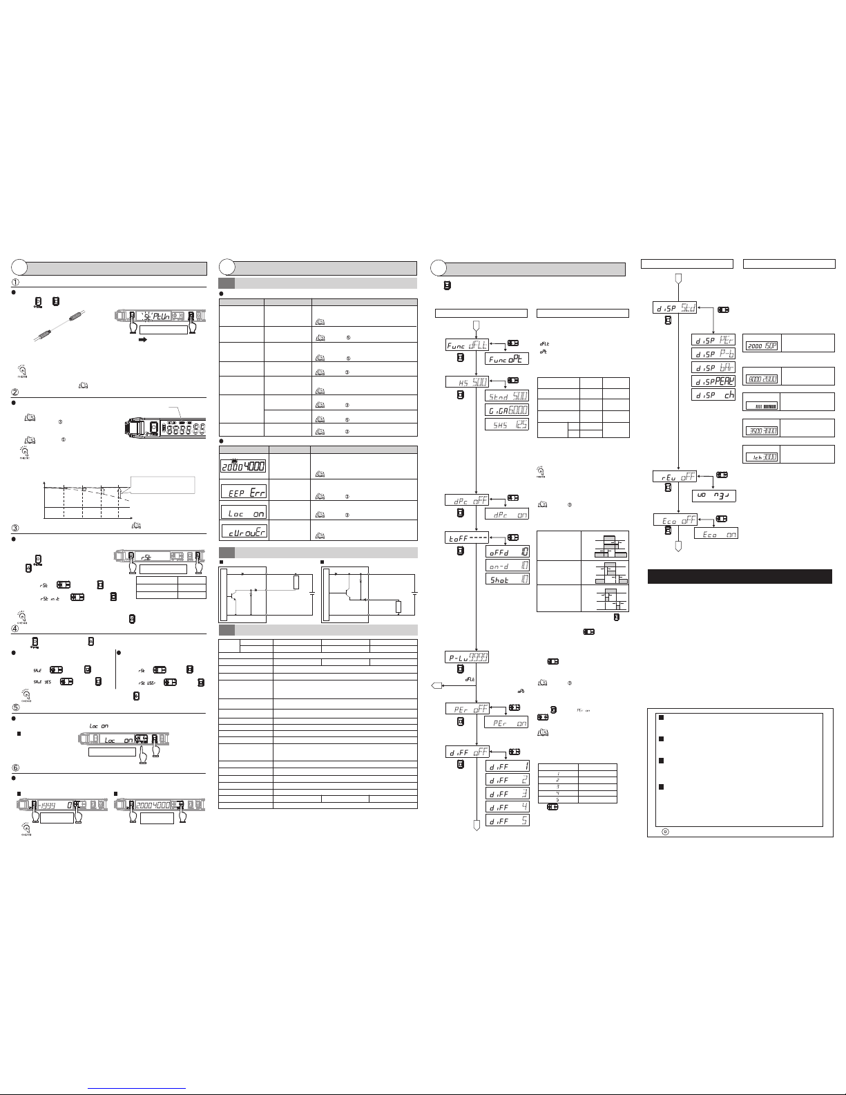
Problem Cause Remedy
Cause Remedy
Error Name / Display
Dust or dirt, temperature
changes or vibration
Use the DPC function to stabilize the incident light level display.
The operation
indicator blinking
Mutual interference
or other reason
Check the Amplifier Units mounted in a group and
turn ON the power again.
Incident light level
displayed in a
negative value
The differential
function is enabled.
Turn OFF the differential function.
Lost tracking of
the settings made
Reset the settings.
ー
The incident light
level has
deteriorated due
to dust or dirt.
Failed internal
data read/out
E3X-HD11, E3X-HD6, E3X-HD14 (NPN Type)
Load
The key lock
function enabled
Over current flowing
to the control output
2000
4000
*1: Either of E3X-CN11 (Master connector: three core) and E3X-CN12 (Slave connector: single core) can be used.
Model
NPN Output
PNP Output
E3X-HD11
E3X-HD41
Number of Control Outputs
Connection Method
Light Source (Wavelength)
Power Supply Voltage
Power Consumption
Control Output
Protection Circuits
Ambient Illumination
Ambient Temperature Range
Ambient Humidity Range
Insulation Resistance
Dielectric Strength
Vibration Resistance
Shock Resistance
Material
1
Pre-wired Type M8 connector type
Wire-saving Connector Type*1
Red 4-element LED (625 nm)
12 to 24 VDC ±10%, ripple (p-p) 10% max.
Possible for up to 10 units *2
Case: Heat resistant ABS (ABS) / Cover: Polycarbonate (PC)
E3X-HD14
E3X-HD44
E3X-HD6
E3X-HD8
Perform the procedure with a workpiece in the area for reflective model setting.
If the setting is made after position tuning, set both the through-beam model and
reflective model with a workpiece.
Troubleshooting
Troubleshooting
Error Display
Power Tuning
DPC Function
Setting Reset
User Save Function
Enable/Cancel
(This procedure)
Enable
Key Lock Function
Zero Reset Function
User Reset Function
4-1
Ratings and Specications
4-3
Normal: 720 mW max. (current consumption: 30 mA max. at power
supply voltage of 24 VDC; 60 mA max. at power supply voltage of 12 VDC)
Power supply reverse polarity protection, output short-circuit protection and
output reverse polarity protection
Mutual Interference Prevention
Operating and storage: 35% to 85% (with no condensation)
20 MΩ min. (at 500 VDC megger)
1,000 VAC at 50/60 Hz for 1 minute
Receiver side: Incandescent lamp: 20,000 lux max. / Sunlight: 30,000 lux max.
Power-saving ECO: 530 mW max. (current consumption: 22 mA max. at power
supply voltage of 24 VDC; 44 mA max. at power supply voltage of 12 VDC)
Load power supply voltage: 26.4 VDC; NPN/PNP open collector;
load current: 50 mA max.; residual voltage: 2 V max.
rst
L/D
Hold button and then hold
button for 3 seconds or longer.
Hold button and then hold button for 3 seconds or longer.
A timer value can be set after pressing
button when a timer menu (other display than
"----") is displayed. Use button to set the
time.
(1 to 9999ms in 1 ms steps; the initial value: 10 ms)
Press button in [ ] menu, then use
button to set the percentage tuning level.
(-99% to 99% in 1% steps; the initial value: -10%)
Disables all button operations. [ ] is displayed when the button is pressed.
Changes the incident light level to "0". The threshold level is also shifted accordingly.
Select [ ] in and press button.
Select [ ] in and press button.
Caution is required; the output is inverted if button is pressed rst.
1.
Initializes all the settings by returning them to the factory defaults.
2.
3.
MODE
Saves the current settings.
Select [ ] in and press button.
Select [ ] in and press button.
Select [ ] in and press
button.
Select [ ] in and press button.
MODE
Reads out the saved settings.
2.
3.
MODE
UP/DOWN
UP/DOWN
UP/DOWN
Incident light level setting: The Step 1 incident level is adjusted to the power tuning level.
Threshold setting: Not changed. If the value is low, it will be set to the minimum
value in which an output is turned ON/OFF correctly.
Refer to "2-3 Smart Tuning Error" for error displays.
Refer to "2-3 Smart Tuning "
DPC Error*
* The DPC indicator blinks.
Wipe the dust off the Fiber Unit detection surface or
other relevant areas and recover the original incident
light level. Then, perform Smart Tuning.
Turn ON the power again. Reset the
settings if the error is not corrected.
Cancel the key lock function.
Check the control output load and adjust it within the
rated value. Check for a load short-circuit.
• Steps 1 and 2 can be reversed.
• The DPC function will be disabled when a smart tuning error occurs, differential function with
maximum sensitivity tuning is performed, or the rst incident light level of the positioning
tuning is low.
• The incident light level is corrected to the power tuning level to maintain stable threshold and
incident light levels. This provides stable detection regardless of the incident level changes
caused by dirty sensor head, position error, or temperature changes.
Approx. 65 g Approx. 22 gApprox. 20 g
Maintenance
4
E3X-HD41, E3X-HD8, E3X-HD44 (PNP Type)
12 to 24 VDC
Black:
Control Output
Black:
Control Output
Brown
Blue
Brown
Blue
12 to 24 VDC
Input/Output Circuit Diagram
4-2
1.
L/D
2.
3.
Cancel
0
1999
-
No digital display
The zero reset function
is enabled.
Cancel the zero reset function.
MODE
UP/DOWN
MODE
UP/DOWN
MODE
UP/DOWN
Current Over
Weight (Main Unit Only)
Maximum connectable units
EEPROM Error
Lock ON
Time
Refer to "4-2 Input/Output Circuit Diagram"
Refer to "1-2 Mounting Amplifier Unit"
Refer to "4-2 Input/Output Circuit Diagram"
and "4-3 Ratings and Specications"
Item
Threshold Value
Control Output
Initial Value
55
(a)
(b)
(c)
(d)
(e)
(a)
(b)
(c)
(d)
(e)
L-on
* Settings for other functions are returned to
the detailed setting initial values.
User-saved settings are retained.
Smart Tuning is canceled.
Hold button for 3 seconds or longer to enter SET mode.
MODE
dp<
%n
hs
500
stnd
shs
dp<
%ff
----
9999
MODE
MODE
MODE
MODE
Detection Function
Response
Time
Light Level
STND
Standard Mode
SHS
Super High-speed
Mode*
GIGA
Giga Mode
HS
High-speed Mode
1 ms
50 µs
55 µs
16 ms
250 µs
12 times
0.25 times
1 time
1 (Standard)
2. Detection Function
per
%ff
per
%n
%ff
per
p-b
bar
3. DPC Function
4. Timer Function
UP/DOWN
9. Inverted Display
8. Digital Display
7. Differential Function
6. Percentage Tuning
MODE
MODE
MODE
MODE
MODE
One-shot Timer
Keeps the output ON for
a specified time regardless
of the workpiece size
variations.
T
T
T
T
T
T
Off-delay Timer
Holds the output ON for
detection by PLC when
the detection time is too
short.
On-delay Timer
Delays the output ON
after detection.
Incident Light
No Incident Light
Incident Light
No Incident Light
Incident Light
No Incident Light
ON
OFF
ON
OFF
L-ON
D-ON
ON
OFF
ON
OFF
L-ON
D-ON
ON
OFF
ON
OFF
L-ON
D-ON
%ff
B
A
SET mode provides the function settings described hereafter. The initial display shown
after transition from one function to another represents the factory default.
UP/DOWN
UP/DOWN
UP/DOWN
UP/DOWN
(IncidentLightLevelExample)
Differential Setting
Response Time
1
2
3
4
5
250 μs
500 μs
1 ms
10 ms
100 ms
Detailed Settings
5
dflt
MODE
UP/DOWN
1. Function Selection
e<%
%ff
e<%
%n
UP/DOWN
MODE
UP/DOWN
Indicators (Green and Red digital displays)
turn OFF in approx. 10 seconds after a key
operation.
10. Eco Function
UP/DOWN
Use button to specify the response time.
UP/DOWN
5. Power Tuning Level
Detects if the absolute value of the incident light level
change of the set response time is larger than the
threshold value. The display shows the change of the
incident light level of the set response time in red.
Smart Tuning is canceled if the detection mode
is changed.
*The communication and mutual interference
prevention functions are disabled when the
detection mode is set to Super High-speed Mode.
(a)
(a)
(b)
(c)
(d)
(b)
(c)
(d)
(a)
(b)
(c)
(d)
Setting Output Timer
Changing the Target Incident Light Level
(Power Tuning Level)
Detecting Transparent or Small Workpiece
Changing Digital Display in RUN Mode for
Specific Purpose
Detecting Incident Light Level Change
10
%n-d
10
std
B
A
Mounting Amplifier in Inverted Direction
Saving Power Consumption
Function Setting Description
Function Setting Description
Changing Functions to Set in SET Mode
[ ]: Functions 1. to 5. can be set.
[ ]: Functions 1. to 10. can be set.
Changing Light Level and Response Time
Stable Detection Regardless of Incident Light
Level Change
Setting Threshold using a Small or Fast Moving
Workpiece
Adjusting Optical Axis
Checking the Channel No. in Group Mounting
The ratio of the incident light
level to the threshold is
displayed in red digital figures.
Holds the peak incident light
level and displays it in green
digital figures.
Checking the Channel No. in
Group Mounting
Displays the current level in the
80 to 120% range against the
threshold value (100%).
A
Function Selection: [ ]
Threshold
Threshold
Peak Light
Level
Peak Light
Level
Bottom Light
Level
Light Level
Checking a Margin Against Threshold
Holds and displays the minimum
value of the peak of the light
incident and the maximum value
of the bottom of the light interruption.
Ch. No. Light Level
Setting for Intuitive Analog Display
120%100%80%
The zero reset function is canceled when either of the DPC function/differential
function/Smart Tuning is performed.
APC (Auto Power Control)
Always ON
16 units
MODE
UP/DOWN
Inverts the display upside down.
The digital display shows the threshold value in
red, and light incident level in green.
Refer to "4-1 Troubleshooting"
10 to 55 Hz with a 1.5-mm double amplitude for 2 hours each in X, Y and Z directions
500 m/s
2
, for 3 times each in X, Y and Z directions
*2: Mutual interference prevention is only possible for up to 6 units, if the E3X-DA-S/MDA sensors applied with
power tuning are grouped with this sensor.
*3: The communication and mutual interference prevention functions are disabled when the detection mode is set to
Super High-speed Mode
150p
3000
3500
3000
L/D
Caution is required; the output is inverted if button is pressed rst.
L/D
2000
4000
UP/DOWN
Use button to set the power tuning level.
[100 to 9999 in 1 steps; the initial value: 9999]
Perform Smart Tuning.
Set the DPC function ON in SET mode.
1.
Refer to "2-3 Smart Tuning"
内部受光量
Internal Incident Light Level
Incident Light
Level
Displayed Incident Light Level
Threshold
Level
Stabilizes the displayed
incident level by correcting
internal incident level changes.
The DPC indicator turns ON
when the DPC function is
effective.
The displayed incident level
decreases and the DPC
indicator starts blinking when
incident level correction is not
possible.
* Press either of UP/DOWN.
Operating: Groups of 1 to 2 Ampliers: −25°C to 55°C
Groups of 3 to 10 Ampliers: −25°C to 50°C
Groups of 11 to 16 Ampliers: −25°C to 45°C
Storage: −30°C to 70°C (with no icing or condensation)
Convenient Setting Features
Restore from the Incident Level Changed due to Dust and Dirt
Stable Detection Regardless of Incident Level Change due to Dust and Dirt
Reset Settings
Save or Read Settings
Prevent Mis-operation
Reset Incident Light Level to "0"
Setting is Completed
Refer to " Detailed Settings".
Refer to " Detailed Settings".
Refer to " Detailed Settings".
Refer to " Convenient Setting Features"
Refer to " Convenient Setting Features"
Refer to " Convenient Setting Features"
Refer to " Convenient Setting Features"
Refer to " Convenient Setting Features"
Refer to " Convenient Setting Features"
Refer to " Convenient Setting Features"
Refer to "2-3 Smart Tuning"
Refer to " Detailed Settings".
Sensor Main Circuit
Sensor Main Circuit
Load
Hold both for 3 sec. or longer
Hold both for 3 sec. or longer
Hold both for 3 sec.
or longer
Hold both for 3 sec.
or longer
Light Level
Ratio
OMRON Corporation
Suitability for Use
EUROPE
OMRON EUROPE B.V. Sensor Business Unit
Carl-Benz Str.4, D-71154 Nufringen Germany
Phone:49-7032-811-0 Fax: 49-7032-811-199
NORTH AMERICA
OMRON ELECTRONICS LLC
One Commerce Drive Schaumburg,IL 60173-5302 U.S.A.
Phone:1-847-843-7900 Fax : 1-847-843-7787
ASIA-PACIFIC
OMRON ASIA PACIFIC PTE. LTD.
No. 438A Alexandra Road #05-05-08(Lobby 2),
Alexandra Technopark, Singapore 119967
Phone : 65-6835-3011 Fax :65-6835-2711
THE PRODUCTS CONTAINED IN THIS SHEET ARE NOT SAFETY RATED.
THEY ARE NOT DESIGNED OR RATED FOR ENSURING SAFETY OF
PERSONS, AND SHOULD NOT BE RELIED UPON AS A SAFETY
COMPONENT OR PROTECTIVE DEVICE FOR SUCH PURPOSES.
Please refer to separate catalogs for OMRON's safety rated products.
OMRON shall not be responsible for conformity with any standards, codes, or
regulations that apply to the combination of the products in the customer's
application or use of the product.
Take all necessary steps to determine the suitability of the product for the
systems, machines, and equipment with which it will be used.
Know and observe all prohibitions of use applicable to this product.
NEVER USE THE PRODUCTS FOR AN APPLICATION INVOLVING
SERIOUS RISK TO LIFE OR PROPERTY WITHOUT ENSURING THAT THE
SYSTEM AS A WHOLE HAS BEEN DESIGNED TO ADDRESS THE RISKS,
AND THAT THE OMRON PRODUCT IS PROPERLY RATED AND
INSTALLED FOR THE INTENDED USE WITHIN THE OVERALL
EQUIPMENT OR SYSTEM.
See also Product catalog for Warranty and Limitation of Liability.
CHINA
OMRON(CHINA) CO., LTD.
Room 2211, Bank of China Tower,
200 Yin Cheng Zhong Road,
PuDong New Area, Shanghai, 200120, China
Phone : 86-21-5037-2222 Fax :86-21-5037-2200
OCT. 2009
500
6000
125
(a)
(b)
(c)
(a)
(b)
(c)
UP/DOWN
3
2
5
4
The incident light level in setting mode is a
reference value. It may be changed when
switched to detection mode.
When the differential function is enabled,
the detection function setting is disabled.
Smart tunings except power tuning are disabled.
The adjustment range of powr tuning is approx.
1 to 1/100 times.
Function Selection: [ ]
D
2000
8000
Refer to " Convenient Setting Features
- Power Tuning"
NPN
PNP
 Loading...