

Page 1

Cat. No. Z152-E1-01
E3X-DRT21 (DeviceNet)
E3X-SRT21 (CompoBus/S)
E3X-CIF11 (RS-422)
Fiber Amplifier Sensor
Communication Units
23(5 $7,21 0$18$/
Page 2

E3X-DRT21 (DeviceNet)
E3X-SRT21 (CompoBus/S)
E3X-CIF11 (RS-422)
Fiber Amplifier Sensor
Communication Units
Operation Manual
Produced Septemb er 2001
Page 3

iv
Page 4

Notice:
r
f
OMRON products are manufactured for use accordin g to proper procedures by a qualified operator
and only for the purposes described in this manual.
The following conventions are used to ind icate and classify pr ecautions in this manual . Always heed
the information provided with them . Failure to heed precautions can result in in jur y to people or damage to property.
!DANGER Indicates an immine ntly hazardous situation whi ch, if not avoided, will result in death or
serious inj ury.
!WARNING Indicates a potentially hazardous situatio n which, if not avoided, could resu lt in death or
serious inj ury.
!Caution Indicates a potentially hazardous situat ion which, if not avoided, may result in minor or
moderate injury, or property damage.
OMRON Product References
All OMRON products are capitalized in this manual. The word “Unit” is also capitalized when it refers to
an OMRON product, regardless of whether or not it appears in the proper name of the product.
The abbreviation “Ch,” which appears in some dis plays and on some OMRON products, often means
“word” and is abbreviated “Wd” in documentation in this sense.
The abbreviation “PLC” means Programmable Controller.
Visual Aids
The following headings appear in the left co lumn of the manual to help you locate different types of
information.
Copyrights
DeviceNet is a registered tradema rk of the ODVA (Open DeviceNet Vendor Association). Othe r product names and company names use d in this manual are the tradema rks or registere d trademarks of
the respective companies. The copyright to t he Fiber Am plifier Sen sor Communicati on Units belo ngs
to OMRON Corporation.
¸ OMRON, 2001
All rights reserved. No part of this publication may be reproduced, stored in a retrieval system, or tran smit ted, in any form, o
by any means, mechanical, electronic, photocopying, recording, or otherwise, without the prior written permission o
OMRON.
No patent liability is assumed with respect to th e use of the in fo rmation c ontain ed he rein. M oreover, because OMRON is con stantly striving to improve its high-quality products, the information contained in this manual is subject to change without
notice. Every precaution has been taken in the preparation of this manual. Nevertheless, OMRON assumes no responsibility
for errors or omissions. Neither is any liability assumed for damages resulting from the use of the information contained in
this publication.
Note Indicates information of pa rticular interest for efficient and convenient opera-
tion of the product.
1,2,3... 1. Indicates lists of one sort or another, such as procedures, checklists, etc.
v
Page 5

TABLE OF CONTENTS
PRECAUTIONS . . . . . . . . . . . . . . . . . . . . . . . . . . . . . . . . . . . ix
1 Intended Audience. . . . . . . . . . . . . . . . . . . . . . . . . . . . . . . . . . . . . . . . . . . . . . . . . . . . . . . . . x
2 General Precautions. . . . . . . . . . . . . . . . . . . . . . . . . . . . . . . . . . . . . . . . . . . . . . . . . . . . . . . . x
3 Safety Precautions . . . . . . . . . . . . . . . . . . . . . . . . . . . . . . . . . . . . . . . . . . . . . . . . . . . . . . . . . x
4 Operating Environment Precautions . . . . . . . . . . . . . . . . . . . . . . . . . . . . . . . . . . . . . . . . . . . xi
5 Application Precautions. . . . . . . . . . . . . . . . . . . . . . . . . . . . . . . . . . . . . . . . . . . . . . . . . . . . .xi
SECTION 1
Overview . . . . . . . . . . . . . . . . . . . . . . . . . . . . . . . . . . . . . . . . . 1
1-1 Features and System Configuration. . . . . . . . . . . . . . . . . . . . . . . . . . . . . . . . . . . . . . . . . . . . 2
1-2 Specifications. . . . . . . . . . . . . . . . . . . . . . . . . . . . . . . . . . . . . . . . . . . . . . . . . . . . . . . . . . . . . 5
1-3 Connecting Fiber Amplifier Units. . . . . . . . . . . . . . . . . . . . . . . . . . . . . . . . . . . . . . . . . . . . . 7
SECTION 2
E3X-DRT21 for Device Net Communications . . . . . . . . . . . 11
2-1 Overview of DeviceNet Communications Model . . . . . . . . . . . . . . . . . . . . . . . . . . . . . . . . . 12
2-2 DeviceNet Communication Unit Part Names and Functions . . . . . . . . . . . . . . . . . . . . . . . . 17
2-3 Operating Procedure for DeviceNet Communication Unit . . . . . . . . . . . . . . . . . . . . . . . . . . 20
2-4 Wiring the DeviceNet Model. . . . . . . . . . . . . . . . . . . . . . . . . . . . . . . . . . . . . . . . . . . . . . . . . 21
2-5 DeviceNet Remote I/O Communications . . . . . . . . . . . . . . . . . . . . . . . . . . . . . . . . . . . . . . . 22
2-6 Explicit Message Communications. . . . . . . . . . . . . . . . . . . . . . . . . . . . . . . . . . . . . . . . . . . . 27
2-7 Setting, Monitoring, and Operating Sensors from the DeviceNet Configurator . . . . . . . . . . 45
SECTION 3
E3X-SRT21 for CompoBus/S Communications . . . . . . . . . 53
3-1 Overview of CompoBus/S Communications Model. . . . . . . . . . . . . . . . . . . . . . . . . . . . . . . 54
3-2 CompoBus/S Communication Unit Part Names and Functions . . . . . . . . . . . . . . . . . . . . . . 56
3-3 Operating Procedure for CompoBus/S Communication Unit. . . . . . . . . . . . . . . . . . . . . . . . 59
3-4 Wiring the CompoBus/S Communication Unit. . . . . . . . . . . . . . . . . . . . . . . . . . . . . . . . . . . 60
3-5 CompoBus/S Remote I/O Communications . . . . . . . . . . . . . . . . . . . . . . . . . . . . . . . . . . . . . 61
SECTION 4
E3X-CIF11 for RS-422 Communications. . . . . . . . . . . . . . . 63
4-1 Overview of RS-422 Communication Unit. . . . . . . . . . . . . . . . . . . . . . . . . . . . . . . . . . . . . . 64
4-2 RS-422 Communication Unit Part Names and Functions. . . . . . . . . . . . . . . . . . . . . . . . . . . 68
4-3 Operating Procedure for RS-422 Communication Unit . . . . . . . . . . . . . . . . . . . . . . . . . . . . 72
4-4 Wiring RS-422 Communication Units . . . . . . . . . . . . . . . . . . . . . . . . . . . . . . . . . . . . . . . . . 73
4-5 CompoWay/F Message Communications . . . . . . . . . . . . . . . . . . . . . . . . . . . . . . . . . . . . . . . 75
vi
Page 6

TABLE OF CONTENTS
SECTION 5
Installation and Dimensions . . . . . . . . . . . . . . . . . . . . . . . . . 97
5-1 Mounting. . . . . . . . . . . . . . . . . . . . . . . . . . . . . . . . . . . . . . . . . . . . . . . . . . . . . . . . . . . . . . . . 98
5-2 Dimensions . . . . . . . . . . . . . . . . . . . . . . . . . . . . . . . . . . . . . . . . . . . . . . . . . . . . . . . . . . . . . . 101
SECTION 6
Errors and Troubleshooting . . . . . . . . . . . . . . . . . . . . . . . . . 103
6-1 Errors and Troubleshooting. . . . . . . . . . . . . . . . . . . . . . . . . . . . . . . . . . . . . . . . . . . . . . . . . .104
Appendices
A Communications Timing . . . . . . . . . . . . . . . . . . . . . . . . . . . . . . . . . . . . . . . . . . . . . . . . . . . 109
B Monitoring Incident Light Levels of E3X-DA6-P Sensors . . . . . . . . . . . . . . . . . . . . . . . . . 111
C DeviceNet Connection Settings . . . . . . . . . . . . . . . . . . . . . . . . . . . . . . . . . . . . . . . . . . . . . . 115
D DeviceNet Device Profile . . . . . . . . . . . . . . . . . . . . . . . . . . . . . . . . . . . . . . . . . . . . . . . . . . . 123
Revision History . . . . . . . . . . . . . . . . . . . . . . . . . . . . . . . . . . . 125
vii
Page 7

About this Manual:
This manual describes the installation and operation of the E3X-DRT21 (DeviceNet), E3X-SRT21
(CompoBus/S), a nd E3X-CIF11 (RS-422) Fiber Amplifier Se nsor Communication Un its. These Units
enable optical fiber com munic ati on s for OMRON E3X- DA-N Digital F ib er Am pl ifier s and E39 - TM1 Terminal Block Units.
Please read this manual carefully and be sure you understand the information provided before
attempting to install or ope rate a Fib er Amplifier Sensor Com munic at ion Uni t. B e s ur e t o read the precautions provided in the following section.
Precautions provides general precautions for using a Fiber Amplifier Sensor Communication Unit and
related devices.
Section 1 provides an overview of the Fiber Amplifier Sensor Communication Units for DeviceNet,
CompoBus/S, and RS-422 c ommunic ations, inc ludin g thei r features, system c onfig urations, s pecific ations, and connection methods. This section also covers the differences between different models.
Section 2 provides details on the Fiber Amplifier Sensor Communication Unit for DeviceNet communications, including proc edures and application examples for remote I/O communica tions and explicit
messages used by the Unit, par t nam es and fun ction s, operation proced ures, wiring , and appl ications
available from the DeviceNet Configurator.
Section 3 provides detai ls on the Fiber Am plifier Sensor Communication Unit for CompoB us/S communications, including proc ed ures and a ppl ic atio n examples for CompoBus/S remote I/O communications used by the Unit, part names and functions, operation procedures, and wiring.
Section 4 provides details on the Fiber Amplifier Sensor Communication Unit for RS-422 communications, including informati on on the model s, procedures, set tings, and applica tion examples of Com poWay/F message communications used by the Unit, par t names and fun ctions, operation procedures,
and wiring.
Section 5 descr ibes the procedure us ed to mount the Fiber Amplifier Sen sor Communication Unit to
DIN Track and provides the dimensions of the Units.
Section 6 provides infor mation for each Communication Unit on the types of errors that m ay occur,
including details on the indicator status, probable causes, and remedies.
The Appendices provide information on communications timing, monitoring incident light levels of
E3X-DA6-P Sensors, DeviceNet connection settings, and the device protocol for DeviceNet.
!WARNING Failure to read and under stand the information provided in th is manual m ay result in p er-
sonal injury or death, damage to th e product, or product failure. Please r ea d ea ch section
in its entirety and be sure you understand the information provided in the section and
related sections before attempting any of the procedures or operations given.
viii
Page 8

PRECAUTIONS
This section provides general precautions for using the Fiber Amplifier Sensor Communication Units and related devices.
The information contained in this section is importa nt for the safe and reliable application of the Fiber Amplifier
Sensor Communication Units. You must read this section and understand the information contained before
attempting to set up or operate a Fiber Amplifier Sensor Communication Unit.
1 Intended Audience . . . . . . . . . . . . . . . . . . . . . . . . . . . . . . . . . . . . . . . . . . . . . x
2 General Precautions . . . . . . . . . . . . . . . . . . . . . . . . . . . . . . . . . . . . . . . . . . . . x
3 Safety Precautions. . . . . . . . . . . . . . . . . . . . . . . . . . . . . . . . . . . . . . . . . . . . . . x
4 Operating Environment Precautions . . . . . . . . . . . . . . . . . . . . . . . . . . . . . . . . xi
5 Application Precautions . . . . . . . . . . . . . . . . . . . . . . . . . . . . . . . . . . . . . . . . . xi
ix
Page 9

Intended Audience 1
1 Intended Audience
This manual is intended for the following personnel, who must also have
knowledge of electrical systems (an electrical engineer or the equivalent).
• Personnel in charge of installing FA systems.
• Personnel in charge of designing FA systems.
• Personnel in charge of managing FA systems and facilities.
2 General Precautions
The user must operate t he product according to t he performance specifications described in the operation manuals.
Before using the product under conditions which are not described in the
manual or applying the produ ct to nuclear control s ystems, railroad systems,
aviation systems, vehicles, combustion systems, medic al equipmen t, amusement machines, safety equipment, and oth er systems, machines, and equi pment that may have a serious influence on lives and property if used
improperly, consult your OMRON representative.
Make sure that the ratings and performan ce charact er is ti cs of the pr od uc t are
sufficient for the systems, machi nes, and equipment, and be sure to provide
the systems, machines, and equipment with double safety mechanisms.
This manual provides information for install ing and operating OMRON Fiber
Amplifier Sensor Communication Units. Be sure to read this manual before
operation and keep this manual close at hand for reference during operation.
!WARNING It is extremely important that a Fiber Amplifier Sensor Communication Unit be
used for the specified pur pose and under the specified co nditions, especial ly
in applications that ca n directly or indir ectly affect human life. You must consult with your OMRON representative before applying a Fiber Amplifier Sensor Communication Unit to the above mentioned applications.
3 Safety Precautions
!WARNING Provide external emer gency stop circ uits, interlock circu its, limit circuits, and
other safety circuits in addition to any provided within the control system to
ensure safety in the event of product failure or errors resulting from external
causes. Incorrect or unexpected operation may result in serious accidents.
x
Page 10

Operating Environment Precautions 4
4 Operating Environment Precautions
Do not operate the control system in the following places.
• Where the Fiber Amplifier Sensor Communication Unit is exposed to
direct sunlight.
• Where the ambient temperature or humidity exceed the specified ranges.
• Where condensation may occur due to radical temperature changes.
• Where there is any corrosive or inflammable gas.
• Where there is excessive dust, saline air, or metal powder.
• Where any water, oil, or chemical may splash on the Fiber Ampli fier S ensor Communication Unit.
• Where the Fiber Amplifier S ensor Com munic ati on Un it i s subj ect to direct
vibration or shock.
!Caution The operating environment of the Fiber Am pli fi er Sen so r Co mmunication Unit
can have a large effect on the longevity and reliability of the system. Improper
operating environments can lea d to mal function, failure, and othe r unforeseeable problems with the Fiber Ampli fier Sensor Communication Uni t. Be sure
that the operating environment is withi n the speci fie d co ndi tio ns at ins tallation
and remains within the specified conditions during the life of the system.
5 Application Precautions
Observe the following precautions when using the Fiber Amplifier Sensor
Communication Unit.
!Caution Failure to abide by the following precautions could lead to faulty operation of
the Fiber Amplifier Sens or Communication Unit or the syst em or could damage the Fiber Ampl ifier Sensor Com munication Uni t. Always heed these precautions.
• Provide proper shielding when installing in the following locations:
• Locations subject to static electricity or other sources of noise.
• Locations subject to strong electromagnetic fields.
• Locations subject to possible exposure to radiation.
• Locations near power supply lines.
• Do not clean the Fiber Ampl ifi er Se nso r C ommuni catio n Unit wi th or gan ic
solvents, such as paint thinner. Organic solvents will dissolve and discolor
the surface of the Unit.
• Take measures to stabilize the power suppl y to conform to the rated supply (the voltage, frequency, etc.) if it is not stable.
• Do not attempt to take a Fiber Amplifier Sensor Communication Unit
apart, to repair a Fiber Amplifier Sensor Communication Unit, or to modify
a Fiber Amplifier Sensor Communication Unit in any way.
• Never attempt to wire a Fiber Amplifier Sensor Communication Unit while
power is being supplied. Doing so may result in serious electrical shock or
electrocution.
• Do not drop a Fiber Amplifi er Sensor Communication Unit or subj ect it to
excessive shock or vibration. Unit failure or malfunction may result.
• Use the specified communications cables.
xi
Page 11

Application Precautions 5
• Wire communications within the specified distances.
• Do not wire communications cables near or in parallel with high-voltage or
high-current lines.
• Do not bend cables past their natural bending radius or pull on cables.
• Check all wiring carefully and completely before supplying power.
• Confirm that the correct polarity has been used in wiring the ter minals
and that the communic ation s and power lines have been otherwise wire d
correctely. Incorrect wiring may result in Unit failure.
• Do not connect or disconnect connectors while the power supply is turned
ON. Doing so may result in Unit failure or malfunction.
• Use the specified power supply voltage.
• Do not turn ON or OFF the power supply to the Mobile Consol e during
communications. Doing so may result in communications errors.
• Tighten the screws on t he co mmuni ca tio ns c onn ec tor s ec urel y. The tightening torque is 0.5 to 0.6 N
¼m.
xii
Page 12

SECTION 1
Overview
This section provides an overview of the Fiber Amplifier Sensor Communication Units for DeviceNet, CompoBus/S, and
RS-422 communications, including their features, system configurations, specificat ions, and connection methods. This
section also covers the differences between different models.
1-1 Features and System Configuration . . . . . . . . . . . . . . . . . . . . . . . . . . . . . . . . 2
1-1-1 Overview. . . . . . . . . . . . . . . . . . . . . . . . . . . . . . . . . . . . . . . . . . . . . . 2
1-1-2 Features. . . . . . . . . . . . . . . . . . . . . . . . . . . . . . . . . . . . . . . . . . . . . . . 2
1-1-3 System Configuration. . . . . . . . . . . . . . . . . . . . . . . . . . . . . . . . . . . . 3
1-2 Specifications . . . . . . . . . . . . . . . . . . . . . . . . . . . . . . . . . . . . . . . . . . . . . . . . . 5
1-2-1 Performance Specifications . . . . . . . . . . . . . . . . . . . . . . . . . . . . . . . 5
1-2-2 General Specifications . . . . . . . . . . . . . . . . . . . . . . . . . . . . . . . . . . . 6
1-3 Connecting Fiber Amplifier Units . . . . . . . . . . . . . . . . . . . . . . . . . . . . . . . . . 7
1-3-1 Identifying Sensors (Fiber Amplifier Units). . . . . . . . . . . . . . . . . . . 7
1-3-2 Number of Sensors Connected . . . . . . . . . . . . . . . . . . . . . . . . . . . . . 7
1-3-3 Supported Fiber Amplifier Units . . . . . . . . . . . . . . . . . . . . . . . . . . . 8
1-3-4 Slave Connectors for Fiber Amplifier Units. . . . . . . . . . . . . . . . . . . 8
1-3-5 Power Supply for Sensors. . . . . . . . . . . . . . . . . . . . . . . . . . . . . . . . . 9
1-3-6 Registering the Number of Sensors . . . . . . . . . . . . . . . . . . . . . . . . . 9
1-3-7 Sensor Reset Switch . . . . . . . . . . . . . . . . . . . . . . . . . . . . . . . . . . . . . 9
1
Page 13

Features and System Configuration Section 1-1
1-1 Features and System Configuration
1-1-1 Overview
The Fiber Amplifier Sensor Communication Units are Communication Units
for E3X-DA-N-series Digital Fiber Amplifi er Units or E39-TM1 Terminal Block
Units. (See note.) The following three models are available.
• E3X-DRT21 for DeviceNet (functions as a DeviceNet slave)
• E3X-SRT21 for CompoBus/S (functions as a CompoBus/S slave)
• E3X-CIF11 for RS-422 (functions as a CompoWay/F slave)
Note In this manual, Digital Fiber Amplifier Units and Terminal Block Units are
referred to collectively as Fiber Amplifier Units.
The Fiber Amplifier S ensor Communication Un its can be connected to Fiber
Amplifier Units with Connectors. Connecting a Fiber Am plifier Sensor Communication Unit to the l eft side of one or more Fiber Amplifi er Units allows
data to be exchanged with the Fiber A mplifier Sensor Units via optical communications.
Note When using a Fibe r Amplifier Sensor Communicatio n Unit for DeviceNet or
CompoBus/S communications, however, a Slave Connector with Cord cannot
be connected to a Fiber Amplifier Unit with a Connector. Use a Cordless
Slave Connector instead.
The E3X-MC11 Mobile Console for Fiber Amplifier Units can also be connected to a Fiber Amplifier Sensor Communication Unit.
1-1-2 Features
Communications between
a Host and Optical
Sensors
Remote I/O
Communications
Message Communications Sending comman ds from the PLC all ows reading parameters (such as those
Setting, Monitoring, and
Operating Sensors from
the Configurator
Mobile Console
Connection
The Fiber Amplifier Sensor Communication Unit enables communications
between optical sensors and a host, such as an OMRON PLC (CS-series, CJseries, C200HX/HG/HE, or o ther OMRON PLC), other manufacturer’s PLCs
that support DeviceNet, and personal computers.
Information on the Fiber Am plifier Un it’s ON/OFF output signa ls and in cident
light levels can be sent to the host PL C (master) using rem ote I/O commun ications without any spe cial programming (suppor ted only for Fiber Amplifier
Units for DeviceNet and CompoBus/S communications).
for incident light levels), writing parameters (such as those for thresholds), and
various teaching operations. (DeviceNet models u se explicit messages, and
RS-422 Communication Units use CompoWay/F commands.)
With DeviceNet models, the DeviceNet Configurator (Ver. 2. 10 or higher) ca n
be used to set Fiber A mplifi er Sens or Co mmunicat ion Uni t pa rame ters (C ommunication Unit settings and Sensor settings) and download them to the
Communication Unit and Fiber Amplifier Unit as a batch.
The E3X-MC11 Mobile C onsole for Fiber Ampl ifier Units ca n be co nnecte d to
the Communication Unit. Th e head for connecting to the Mobile Console is
not required when it is connected to a Communication Unit.
Note The Mobile Console ca n be us ed in co nju n ction with monitori ng ON /OFF out-
put signals throug h remote I/O com munications. The Mobile Console canno t
be used, however , in conjunction with remote I/O communications for monitoring incident light levels, message communications, and using the Configurator
for transferring device parameters.
2
Page 14
Features and System Configuration Section 1-1
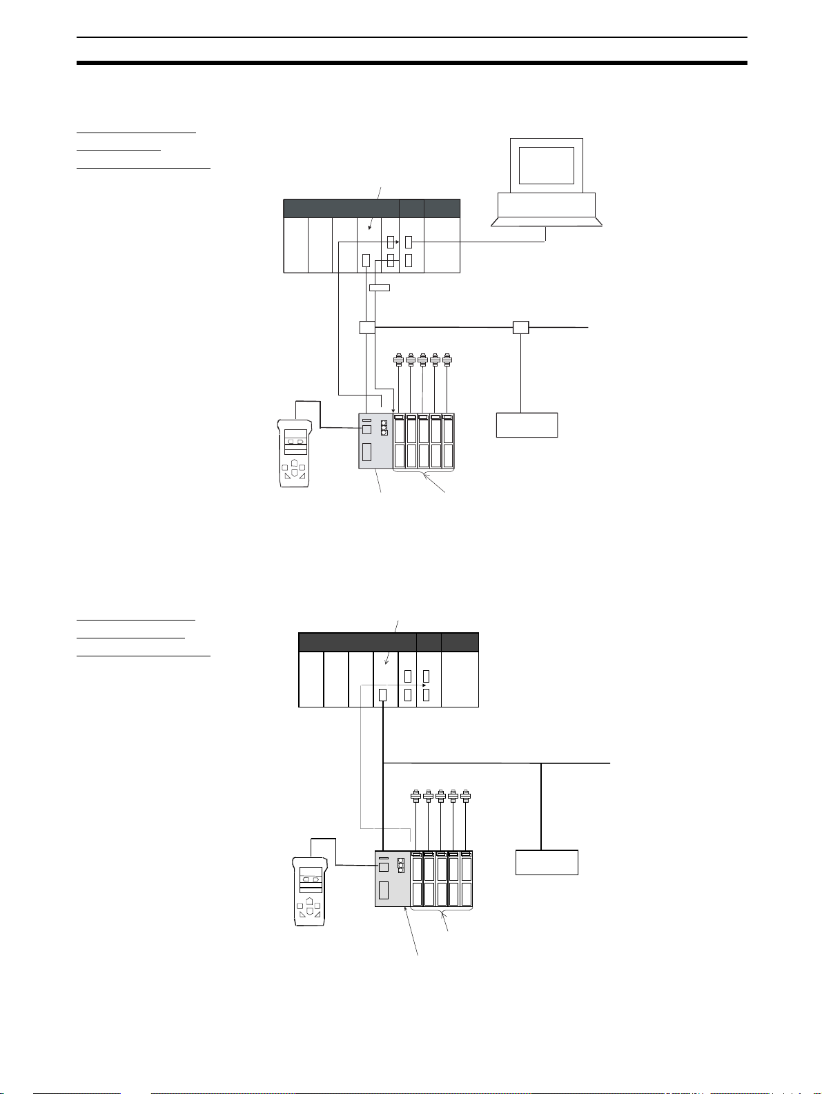
1-1-3 System Configuration
E3X-DRT21 for
DeviceNet
Communications
DeviceNet Configurator
CS/CJ-series DeviceNet Unit
PLC
Serial connector
(For setting, monitoring,
and operating Sensors)
Explicit message
DeviceNet
Fiber Sensors
DeviceNet slave
E3X-MC11
Mobile
Console
Note The Mobile Console cannot be used at the same time as
E3X-DRT21 Fiber
Amplifier Sensor
Communication
Unit for DeviceNet
explicit messages communications and setting, monitoring, and operating from Configurator.
E3X-DA-N Digital Fiber
Amplifier Unit (Uses a
Cordless Slave Connector.)
E3X-SRT21 for
CompoBus/S
Communications
Remote I/O
communications
E3X-MC11 Mobile
Console
CompoBus/S Master Unit
PLC
CompoBus/S
Fiber Sensors
E3X-DA-N Digital Fiber Amplifier Unit
(Uses a Cordless Slave Connector.)
E3X-SRT21 Fiber Amplifier
Sensor Communication
Unit for CompoBus/S
CompoBus/S slave
3
Page 15
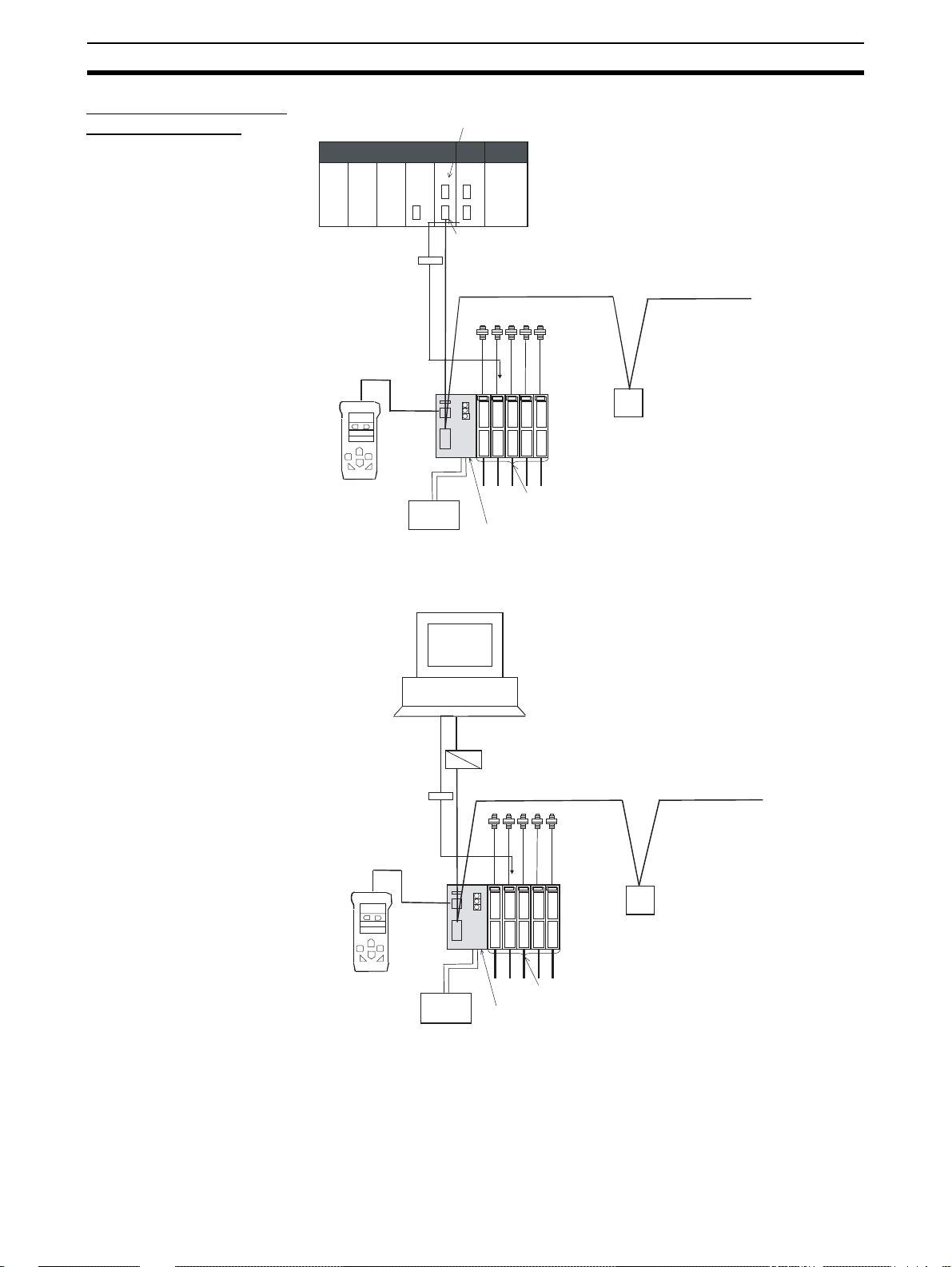
Features and System Configuration Section 1-1
E3X-CIF11 for RS-422
Communications
With PLC as Master
Serial Communications
Board/Unit
PLC
CompoWay/F master
CompoWay/F
message
E3X-MC11
Mobile
Console
Note The Mobile Console cannot be used at the same
time as CompoWay/F message communications.
for protocol macros
Power
supply
RS-422 (CompoWay/F)
Fiber
Sensors
CompoWay/F slav e
component
E3X-DA-N Digital Fiber Amplifier Unit
E3X-CIF11 Fiber Amplifier Sensor
Communication Unit for RS-422
With Personal Computer
as Master
Personal computer
RS-232C
B500-AL004
CompoWay/F
message
E3X-MC11
Mobile Console
Note The Mobile Console cannot be used at same
Power
supply
time as CompoWay/F message communications.
RS-422 (CompoWay/F)
Fiber
Sensors
CompoWay/F slave
component
E3X-DA-N Digital Fiber Amplifier Unit
E3X-CIF11 Fiber Amplifier Sensor
Communication Unit for RS-422
4
Page 16

Specifications Section 1-2
1-2 Specifications
1-2-1 Performance Specifications
Item Specification
E3X-DRT21 E3X-SRT21 E3X-CIF11
Communications method DeviceNet CompoBus/S RS-422
Communications Remote I/O
communications
Messages communications
Setting, monitoring, and
operating Sensors from Configurator
Mobile Console connection Yes
Power supply (Shared by Communication Unit and all Fiber Am plifier
Units connected to it.)
Maximum number of Sensors that
can be connected per Unit.
(See note 1.)
Applicable Fiber Amplifier Units The following Fiber Amplifier Units with Connectors are supported (See note 2.):
Applicable Slave Connectors for
Fiber Amplifier Units
Power supply cable None None Provided.
ON/OFF data, status, and monitoring incident light levels
(Functions as DeviceNet slave.)
Explicit messages No Functions as
Supported from DeviceNet Configurator
(depends on the parameter editi ng and
device monitoring functions of the slave).
Cannot be used at the same time as monitoring incident light levels from remote I/O
communications, using explicit messages
communications, or setting, monitoring, or
operating Sensors from the Configurator.
From DeviceNet communications co nnector
13 or 16 (depending on the mode used) 6 or 14 (depending
E3X-DA6
E3X-DAB6
E3X-DAG6
E3X-DA6TW
E39-TM1
E3X-DA6-P
E3X-DA8
E3X-DAB8
E3X-DAG8
E3X-DA8TW
E3X-CN02 Cordless Slave Connector only E3X-CN02 Cord-
ON/OFF data and
status
(Functions as CompoBus/S slave.)
No No
--- Cannot be used
From CompoBus/S
communications
connector
on the setting fo r
maximum number
of Sensors)
less Slave Connector only
No
CompoWay/F
slave.
at the same time
as CompoWay/F
message communications.
From power supply cable
16
E3X-CN12 Slave
Connector with
Cord or E3XCN02 Cordless
Slave Connector
Note 1. Fiber Amplifier Units that are allocated two unit numbers must be counted
as two Units when counting the number of connected Sensors.
2. Prewired models (E3X-DA11/21/41/51-N, E3X-DAB11-N, etc.) and waterresistant models can not be used. Connecting these Uni ts will di sable the
power reset switch.
5
Page 17
Specifications Section 1-2
e
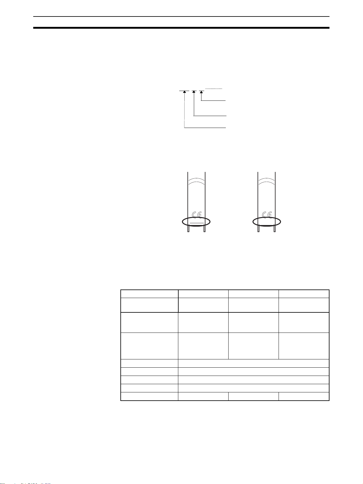
3. The following Fiber Amplifier Units can be connected to products from specific lots (or later) only:
E3X-DA6, E3X-DA8, E3X-DAB6, E3X-DAB8, E3X-DAG6, E3X-DAG8,
E3X-DA6TW, and E3X-DA8TW
Even one Unit from a previous lot cannot be connected. The Units that can
be connected must have the following lot numbers or later.
Lot No.
18 6 01
Another method for distinguishing which Units can be connected is by
checking whether the printed information “MADE IN JAP AN” on the front is
underlined or not. This information is underlined for those Units that can be
connected.
• Underlined
Manufactured on June 18, 2001
Year of manufacture expressed as last two
digits of the year.
Month of manufacture. Oct., Nov., and Dec. ar
expressed as X, Y, and Z respectively .
Day of manufacture.
• N ot underlined
The printed infor mation “MADE IN JAPAN” indicat es whether conn ection
is possible, as follows:
• Underlined: Can be connected to Communication Unit.
• Not underlined: Cannot be connected to Communication Unit.
1-2-2 General Specifications
Model E3X-DRT21 E3X-SRT21 E3X-CIF11
Communications
method
Power supply voltage 11 to 25 VDC 14 to 26.4 VDC 11.4 to 26.4 VDC
Internal current consumption (per Communication Uni t) (See
note.)
Ambient temperature –20 to 55C
Ambient humidity Operating and storage: 35% to 85% (with no condensation)
Storage temperature –30 to 70C
Dimensions 30 34.6 71.3 mm (W H D)
Weight (packed state) Approx. 150 g Approx. 150 g Approx. 200 g
Brown :
12 to 24 VDC
Blue : 0 V
Black :
OUTPUT
MADE IN JAPAN
Brown :
12 to 24 VDC
Blue : 0 V
Black :
OUTPUT
MADE IN JAPAN
DeviceNet CompoBus/S RS-422
(12 VDC –5% to
24 VDC +10%)
70 mA max. 30 mA max. 40 mA max.
Note The current supplied to the Sensor is not included in the specification.
6
Page 18
Connecting Fiber Amplifier Units Section 1-3
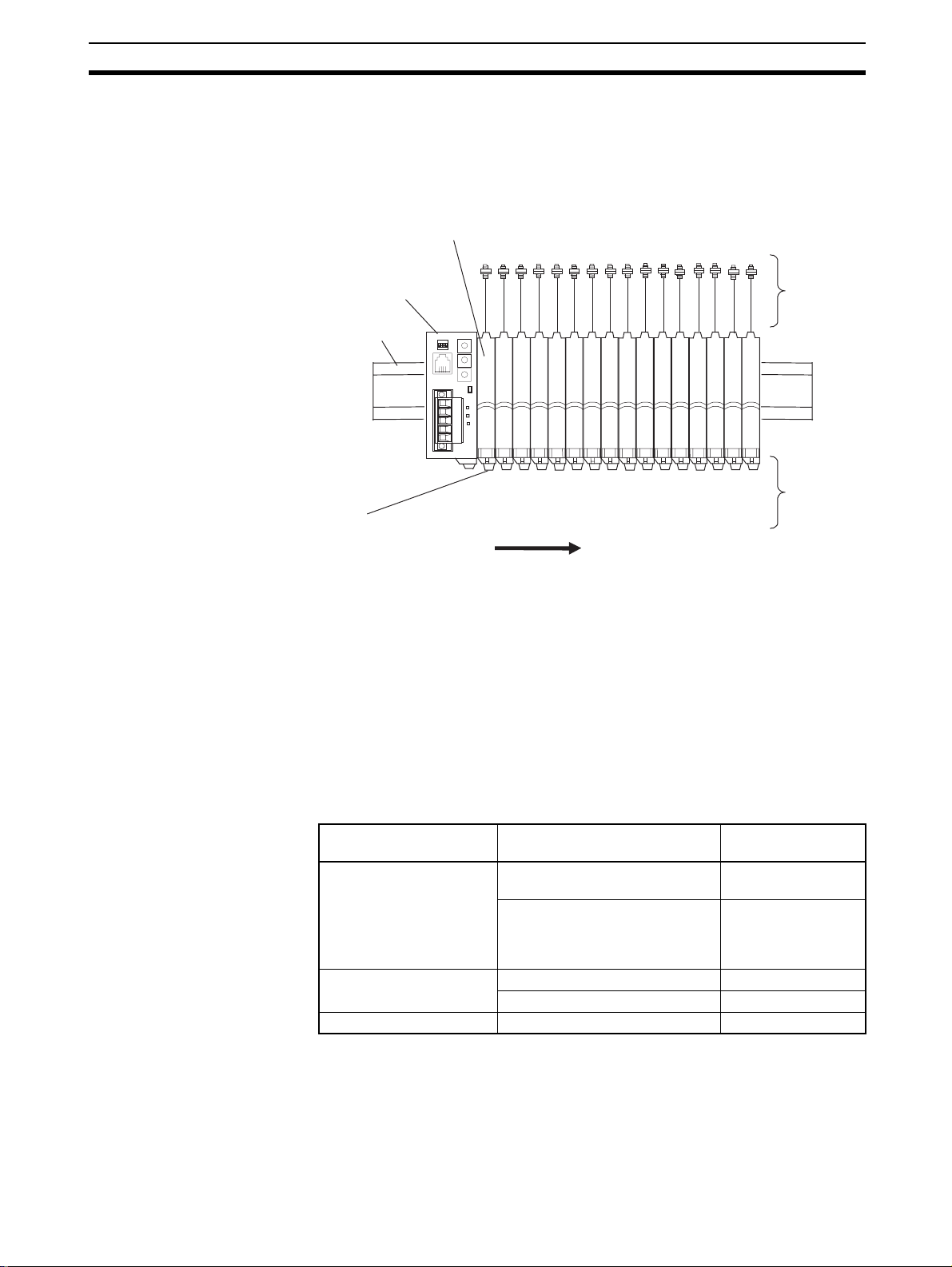
1-3 Connecting Fiber Amplifier Units
1-3-1 Identifying Sensors (Fiber Amplifier Units)
Fiber Amplifier Units are connected serially to the right side of the Fiber
Amplifier Sensor Communication Unit, as shown in the following diagram.
Fiber Amplifier Units
Fiber Amplifier Sensor
Communication Unit
DIN Track
Fiber Amplifier Unit
Slave Connectors
MS
NS
SS
←←←←←←←←←←←←←←←
Unit 1
Unit 2
Unit 3
Unit 4
Unit 5
Unit 6
Unit 7
Unit numbers in ascending order from the left.
Unit 10
Unit 8
Unit 9
Unit 11
Unit 12
Unit 13
Unit 14
Unit 15
←
Unit 16
Fiber
Sensors
Connectors
The Fiber Amplifi er Units con nected to the Co mmunica tion Un it ar e ide ntifie d
according to their unit numbe rs. Unit numbers are automatically assigned to
the Units in order from unit number 1 starting from the Unit next to the Communication Unit.
Some Fiber Amplifier Units, i.e., the E3X-DA6TW and E3X-DA8TW, are
assigned two unit numbers.
1-3-2 Number of Sensors Connected
The number of Sensors ( i.e., the number of Fibe r Amp lifie r Unit s) that c an be
connected depends o n the type of Communi cation Unit us ed and its settings
as follows:
Model Setting Number of Sensors
E3X-DRT21 f or De viceNet Remote I/O communications
E3X-SRT21 for CompoBus/S
E3X-CIF11 for RS-422 --- 16 max.
Note Fiber Amplifier Units that are allocated two unit numbers (E3X-DA6TW, E3X-
DA8TW) must be counted as two Units when counting the number Sensors.
connected
13 max.
(one-word mode)
Remote I/O communications
16 max.
(two-word mode or two-word
mode with incident light level
monitoring)
One allocated node address 6 max.
Two allocated node addresses 14 max.
7
Page 19

Connecting Fiber Amplifier Units Section 1-3
1-3-3 Supported Fiber Amplifier Units
The Communication Unit can be connected to the following Fiber Amplifier
Units.
Model
number
E3X-DA6 Standard model NPN None 1 1
E3X-DA8 PNP
E3X-DA6-P ON/OFF inci-
E3X-DA6TW Twin-output
E3X-DA8TW PNP
E3X-DAB6 Mark-detecting
E3X-DAB8 PNP
E3X-DAG6 Mark-detecting
E3X-DAG8 PNP
E39-TM1 Terminal Block
Unit type Output
NPN
dent light levelmonitoring
model
(See note 1.)
NPN 2 2
model
NPN 1 1
model
(blue LED)
NPN
models
(green LED)
NPN/PNP --- --Unit
type
Monitor
output
Number of
thresholds
Number of
allocated
unit numbers
Note 1. The incident light level can be monitored when Unit is turned ON or OFF.
2. Prewired Units (E3X-DA11/21/41/51-N, E 3X-DA B11-N, etc.) and Waterresistant Units (such as E3X -DA14V) cannot be used. Connecting these
Units will disable the power reset switch.
3. Connect ions of E3X-D A6/8, E3X-DA B6/8, E3X- DA G6/8, E3X-D A6T W , and
E3X-DA8TW are restricted depend ing on the lot number. Refer to page 6
for details on restrictions.
4. Install the E39-TM1 Terminal Block Unit as far away from the Communication Unit as possible.
1-3-4 Slave Connectors for Fiber Amplifier Units
Fiber Amplifier Unit s must be used with Slave Connectors ( purchased separately). When connecting a Fibe r Ampli fier S ensor Com municat ion Unit , however, th e Slave Connector tha t ca n be connected to the Fib er Am pl ifier Uni t is
restricted accor ding to the Communication U nit use d, as shown in the following table.
(Yes: Can be used; No: Cannot be used)
Fiber Amplifier Sensor
Communication Unit
E3X-DRT21 (DeviceNet) Yes No No
E3X-SRT21 (CompoBus/S) Yes No No
E3X-CIF11 (RS-422) Yes Yes No
Note Do not use a E3X-CN11 or E3X-CN21 Mas ter Connector with a Fibe r Ampli-
fier Unit.
8
Slave Connector for Fiber Amplifier Unit
Cordless With 1-wire cord With 2-wire cord
E3X-CN02 E3X-CN12 E3X-CN22
Page 20

Connecting Fiber Amplifier Units Section 1-3
1-3-5 Power Supply for Sensors
The Communication Unit supplies power to the Fiber Amplifier Units. The following table shows the methods u sed to su pply power to the Co mmunicatio n
Unit and all Fiber Amplifier Units connected to it.
Model Power supply method
E3X-DRT21 (DeviceNet) From DeviceNet communications power supply.
E3X-SRT21 (CompoBus/S) From CompoBus/S communications power supply.
E3X-CIF11 (RS-422) From power supply cable.
1-3-6 Regi stering the Number of Sensors
To detect wh ether communica tions with F iber Amplifi er Units are n ormal, th e
number of Fiber Amplifier Units connected must be registered. When the
number of Fiber Amplifier Units connected is registered, errors can be
detected when there is no optical communications response from Sensors
due to malfunctions in Fiber Amplifier Units. The errors can be detected by the
difference between the number of Fiber Am plifier Units communicating and
the number registered as connected.
A difference between the number of Fiber Amplifier Units connected and th e
number of registered Units is indicated as follows:
• The SS indicator lights red.
• The Sensor Communications Error Flag turns ON.
The following table shows the method used to set the number of Sensors connected to the Unit
E3X-DRT21 (DeviceNet) When pin 3 on the DIP switch is OFF:
E3X-SRT21 (CompoBus/S) Use the rotary switch.
E3X-CIF11 (RS-422) When pin 3 on the DIP switch is OFF:
Model Setting method
Use the rotary switch.
When pin 3 on the DIP switch is ON:
Use the Configurator or e xp lic it messages.
Use the rotary switch.
When pin 3 on the DIP switch is ON:
Use CompoWay/F messages.
Note Fiber Amplifier Units that are allocated two unit numbers (E3X-DA6TW, E3X-
DA8TW) must be counted as two Units when counting the number Sensors.
1-3-7 Sensor Rese t Sw it ch
The sensor reset switch is used to replace or add Fiber Amplifier Units without
turning OFF power to the Fiber Amplifier Sensor Communication Unit.
With the Fiber Amplifier Sensor Communication Unit power ON, replace or
perform required work on the Fiber Amplifier Units. After completing work,
press the reset switch to reset all Fiber Amplifier Units and restart normal
communications between the Fiber Amplifier Sensor Communication Unit and
Fiber Amplifier Units.
9
Page 21

Connecting Fiber Amplifier Units Section 1-3
10
Page 22

SECTION 2
E3X-DRT21 for Device Net Communications
This section provides details on the Fiber Amplifier Sensor Communication Unit for DeviceNet communications, including
procedures and application examples for remote I/O communications and explicit messages used by the Unit, part names
and functions, operation procedures, wiring, and applications available from the DeviceNet Configurator.
2-1 Overview of DeviceNet Communications Model. . . . . . . . . . . . . . . . . . . . . . 12
2-1-1 Introduction. . . . . . . . . . . . . . . . . . . . . . . . . . . . . . . . . . . . . . . . . . . . 12
2-1-2 DeviceNet Communications Overview . . . . . . . . . . . . . . . . . . . . . . 12
2-1-3 Using Remote I/O Communications: Example . . . . . . . . . . . . . . . . 15
2-1-4 Using Explicit Message Communications: Example . . . . . . . . . . . . 15
2-2 DeviceNet Communication Unit Part Names and Functions . . . . . . . . . . . . . 17
2-3 Operating Procedure for DeviceNet Communication Unit. . . . . . . . . . . . . . . 20
2-4 Wiring the DeviceNet Model . . . . . . . . . . . . . . . . . . . . . . . . . . . . . . . . . . . . . 21
2-5 DeviceNet Remote I/O Communications . . . . . . . . . . . . . . . . . . . . . . . . . . . . 22
2-5-1 Master Word Allocations . . . . . . . . . . . . . . . . . . . . . . . . . . . . . . . . . 22
2-6 Explicit Message Communications. . . . . . . . . . . . . . . . . . . . . . . . . . . . . . . . . 27
2-6-1 Basic Format of Explicit Messages . . . . . . . . . . . . . . . . . . . . . . . . . 27
2-6-2 READ Command . . . . . . . . . . . . . . . . . . . . . . . . . . . . . . . . . . . . . . . 29
2-6-3 WRITE Command . . . . . . . . . . . . . . . . . . . . . . . . . . . . . . . . . . . . . . 36
2-6-4 Operation Commands. . . . . . . . . . . . . . . . . . . . . . . . . . . . . . . . . . . . 40
2-6-5 List of Error Codes . . . . . . . . . . . . . . . . . . . . . . . . . . . . . . . . . . . . . . 42
2-6-6 Using Explicit Messages: Example . . . . . . . . . . . . . . . . . . . . . . . . . 43
2-7 Setting, Monitoring, and Operating Sensors from the DeviceNet Configurator 45
2-7-1 Overview. . . . . . . . . . . . . . . . . . . . . . . . . . . . . . . . . . . . . . . . . . . . . . 45
2-7-2 Setting the Communication Unit and Sen so r s, and Downloading . . 46
2-7-3 Uploading to Communication Unit and Monitoring/Setting
Parameters Online. . . . . . . . . . . . . . . . . . . . . . . . . . . . . . . . . . . . . . . 49
2-7-4 Sensor Operations. . . . . . . . . . . . . . . . . . . . . . . . . . . . . . . . . . . . . . . 50
2-7-5 Online Monitoring . . . . . . . . . . . . . . . . . . . . . . . . . . . . . . . . . . . . . . 51
11
Page 23
Overview of DeviceNet Communications Model Section 2-1
2-1 Overview of DeviceNet Communications Model
2-1-1 Introduction
The E3X-DRT21 for DeviceNet communications is a Communication Unit that
uses the DeviceNet to communicat e with one or more Fi ber Optical Senso rs
through Fiber Amplifier Units, including monitoring ON/OFF output signals
and incident light levels, writing parameters, and controlling operation.
Remote I/O communications can be use d to monitor ON/OFF output signals
and incident light levels without special programming. Explicit m essages can
be used to read and write parameters and the DeviceNet Configurator
enables transferring and monitoring parameters as a batch.
Note When DeviceNet Communication Units are used, however, Fiber Amplifier
Units can output ON/OF F signals via communi cations only. (Fiber A mplifier
Units can be connecte d to Cordless Slave Connectors only. They cannot be
connected to Slave Connectors with Cords.)
Refer to the following manuals when using a DeviceNet Communication Unit:
DeviceNet Operation Manual (Cat. No. W267) and DeviceNet Slave Manual
(Cat. No. W347).
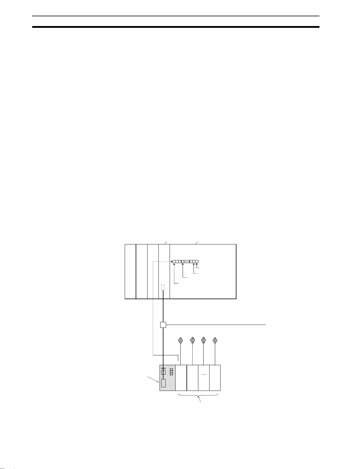
2-1-2 DeviceNet Communications Overview
Remote I/O
Communications
Words in the IN Area of the master can be allocated to the E3 X- DRT21 Communication Unit for storage of the ON/OFF data, status data, and incident light
levels of the Sensors.
DeviceNet Unit CPU Unit
Remote I/O
communications
E3X-DRT21 Fiber
Amplifier Sensor
Communication
Unit for DeviceNet
Remote I/O IN
Area
Sensor
Communications Flag
DeviceNet
Unit
1
E.g., 1-word
mode
Unit 1 ON/OFF
Unit 2 ON/OFF
Unit 13 ON/OFF
Unit
2
PLC
Fiber Sensors
Unit
13
12
E3X-DA-N Digital Fiber Amplifier Unit
(Uses Cordless Slave Connector.)
Page 24
Overview of DeviceNet Communications Model Section 2-1
Communications mode Words Communications data Number of
Sensors
Remote I/O c ommunications
one-word mode
Remote I/O comm unications,
two-word mode
One word in
IN Area
Two words in
IN Area
Sent to the master:
ON/OFF output signals for up to 13 Sensors .
Sent to the master:
ON/OFF output signals for up to 16 Sensors .
13 max. ---
16 max.
Number of Sensors able to communicate.
Number of Sensors connected.
Remote I/O c ommunications
two-word mode with incident
light level monitoring
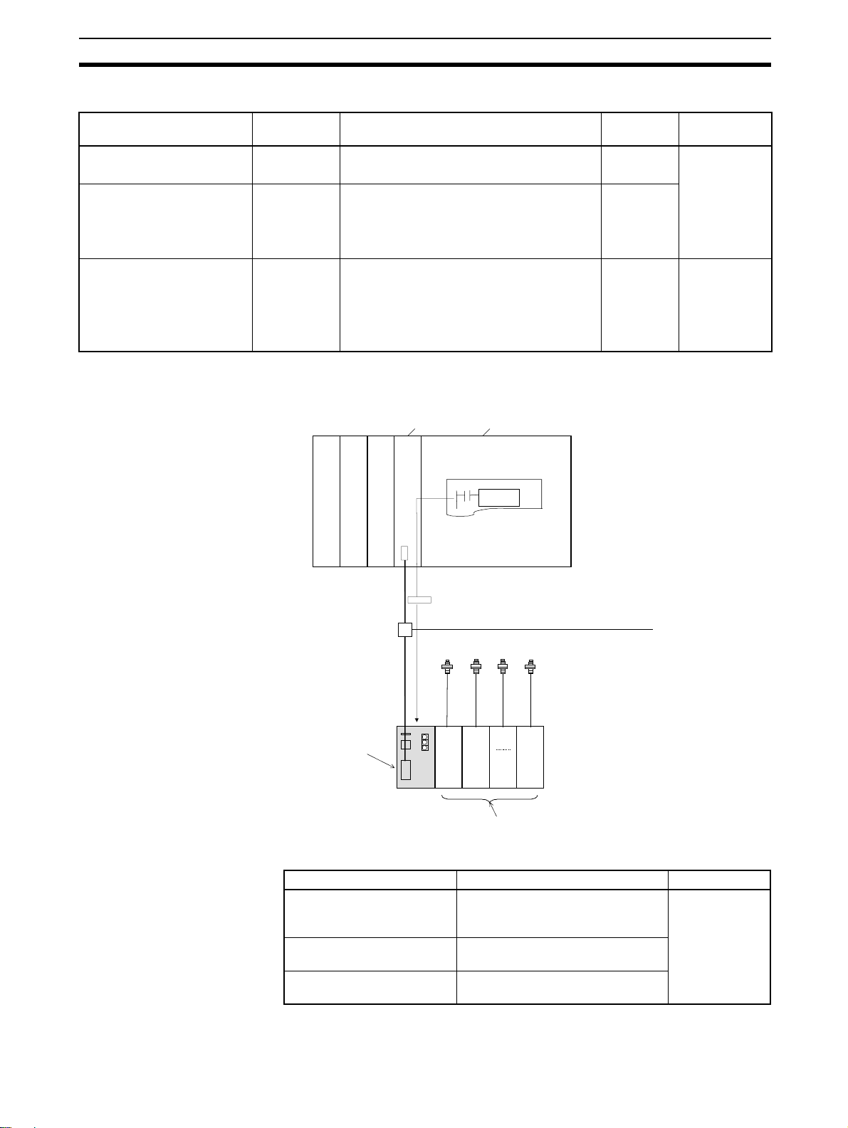
Explicit Message
Communications
Two words in
IN Area plus
words for
number of
Sensors connected
Sent to the master:
ON/OFF output signals for up to 16 Sensors .
Number of Sensors able to communicate.
Number of Sensors that are connected.
Incident light levels of up to 16 Sensors.
16 max. Incident light
Sending explicit messages to the E3X-DRT21 Communication Unit enables
reading and writing Sensor parameters.
DeviceNet Unit CPU Unit
PLC
Ladder program
CMND(490), etc.
Conditions
levels cannot
be monitored if
Mobile Console is connected.
E3X-DRT21 Fiber
Amplifier Sensor
Communication
Unit for DeviceNet
E3X-DA-N Digital Fiber Amplifier Unit
(Uses Cordless Slave Connector.)
Message Communication data Conditions
Sends EXPLICIT READ
command
Sends EXPLICIT WRITE
command
Sends EXPLICIT OPERATION command
Explicit message
DeviceNet
Fiber Sensors
Unit 1Unit
2
Unit
13
Reads parameters, including ON/
OFF data, incident light levels, and
thresholds.
Writes parameters, including maximum sensitivity, and thresholds.
Performs various operations including teaching and fine tuning.
Cannot be used
when a Mobile
Console is connected.
13
Page 25
Overview of DeviceNet Communications Model Section 2-1
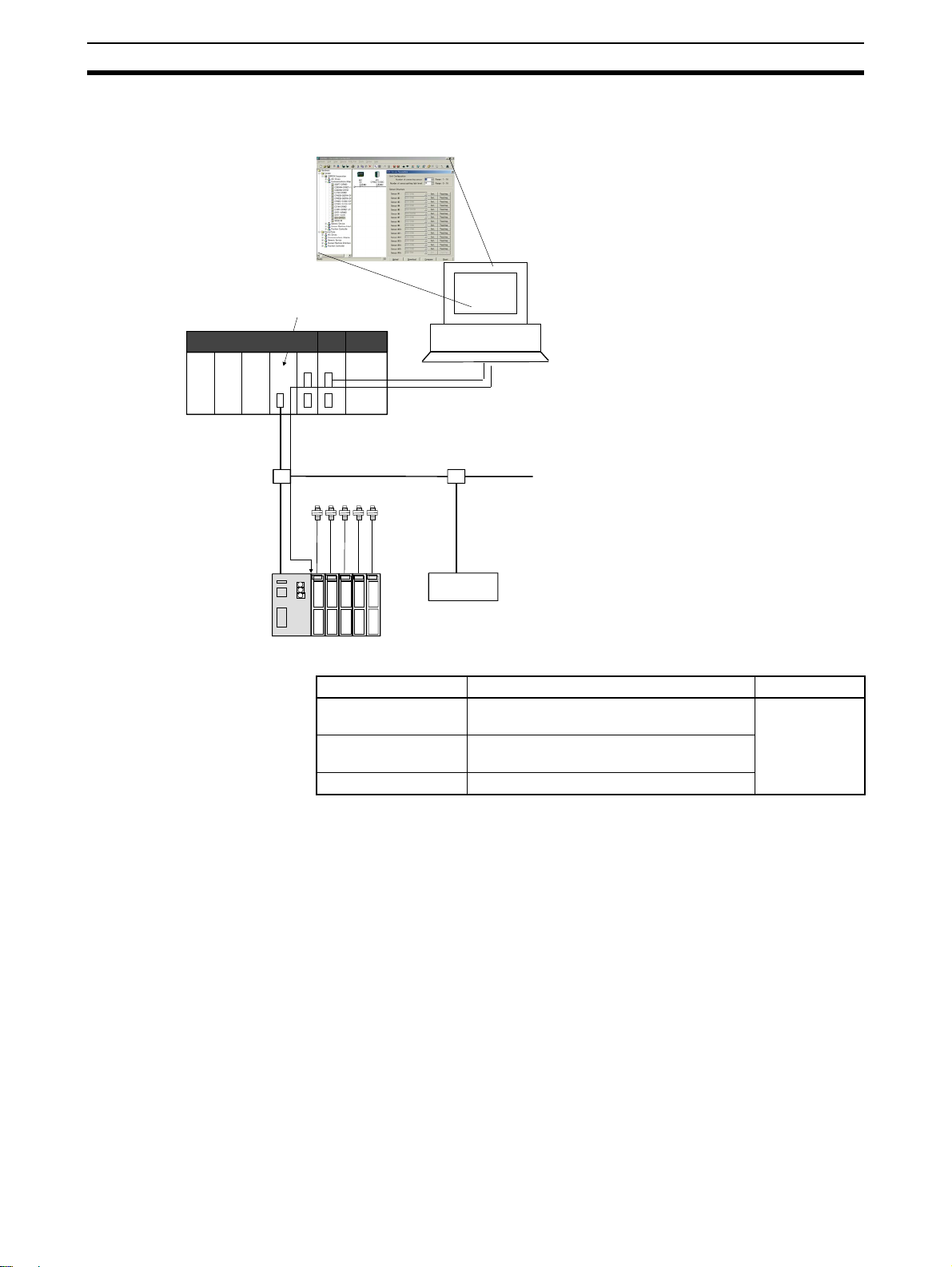
Transferring, Monitoring,
and Operating from the
DeviceNet Configurator
CS/CJ-series DeviceNet Unit
A DeviceNet Configurator (Ver. 2.10 or higher) can be used to read and write
Sensor parameters from a personal computer.
DeviceNet
Configurator
PLC
Serial connector
Operating and monitoring Sensor settings from Configurator
• Setting and downloading Sensor data.
• M onitoring Sensor ON/OFF data, incident light levels, etc.
DeviceNet
Fiber Sensors
• Performing Sensor teaching operations.
E3X-DRT21 Fiber
Amplifier Sensor
Communication Unit
for DeviceNet
DeviceNet slave
Type Communications contents Conditions
Sensor parameter
setting
Writes any parameters, including maximum
sensitivity, and thresholds.
Sensor monitoring Reads any parameters, including ON/OFF
data, incident light levels, and thresholds.
Sensor teaching Performs various teaching operations.
Cannot be
used when
Mobile Console is connected.
14
Page 26
Overview of DeviceNet Communications Model Section 2-1
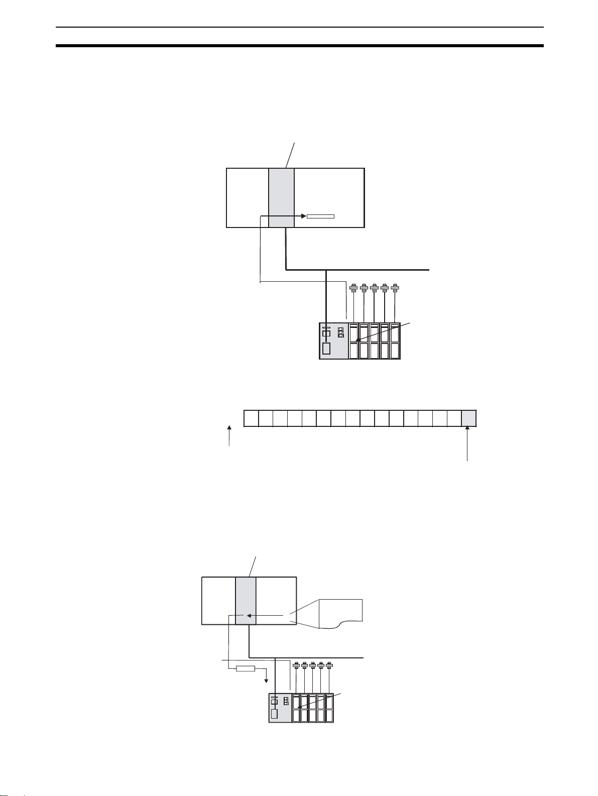
2-1-3 Using Remote I/O Communications: Example
The following example is for monitoring the ON/OFF out put status of Fiber
Amplifier Unit 1 using one -word mode (DI P switch pins 1 and 2 are OFF) and
E3X-DRT21 DeviceNet node address 00.
CS1W-DRM21 DeviceNet Unit with fix ed
allocations for remote I/O communications
CS1 CPU Unit
IN Area
DeviceNet
Reflected in IN Area
E3X-DRT21 Node
address 00
IN Area (fixed allocation area 1)
Bit
CIO 3300
Node address 00
15 14 13 12 11 10 09 08 07 06 05 04 03 02 01 00
Sensor ON/OFF output status for Unit 1
Fiber Sensors
Unit 1 for which
ON/OFF data is
being monitored.
2-1-4 Using Explicit Message Communications: Example
The following example is for setting the maximum sensitivity of Unit 1.
CS1W-DRM21 DeviceNet Unit, Unit 0
(unit address: FE Hex or 10 Hex)
DeviceNet node address: 05
Explicit message
E3X-DRT21
Node address 00
CS1 CPU
Unit
DeviceNet
CMND(490) instruction
Fiber Sensors
Unit 1 for which
maximum sensitivity
is being set.
15
Page 27

Overview of DeviceNet Communications Model Section 2-1
■ Command Format for Setting Maximum Sensitivity
Send the following explicit message.
Destination
node
address
00 Hex 16 Hex 009C Hex 0001 Hex None 30 Hex
Note When using the CMND(490) i nstr uction to se nd the attribute I D and data, set
them in the righ tmos t byte (bits 0 0 t o 07 ) , an d s et the le ftmo st byte (bit s 08 to
15) to 00 Hex. (In the above example, the data is set to 0030 Hex.)
When the explicit message has no attribute ID, omit the words for the attribute
ID in the command data specified for the CMND(490) instruction.
Service
Code
Class ID Instance ID Attribute ID Data
Execute
condition
S D01000
D01001 0 0 1 6
D01002 0 0 9 C
D01003 0 0 0 1
D01003 3 0 0 0
DD02000
C D00000
D00001 0 0 0 A
D00002 0 0 0 1
D00003 0 5 F E
D00004 0 0 0 0
D00005 0 0 3 C
A20200
Network
Communications
Enabled Flag
2
0009
151100 or
152412
Online status or
message
communications
enabled
801
Sends 10 bytes of
CMND
D01000
D02000
D00000
Command code
Slave node address: 00, Service code: 16 Hex
Class ID: 009C Hex
Instance ID: 0001 Hex (unit number)
Data: 30 Hex (fixed)
First word of response storage area.
Command data bytes: 9
Response data bytes
Destination network address: 1
Destination DeviceNet node address: 05 Hex
Destination unit address: FE Hex (or 10 Hex)
Response required, communications port No.: 0, retries: 0 Hex
Response monitoring time: 6 s
command data starting at
D01000 to node address 05,
and stores the10 bytes of
response data in local node
starting at D02000 (D00000
is used for control data).
16
Page 28
DeviceNet Communication Unit Part Names and Functions Section 2-2
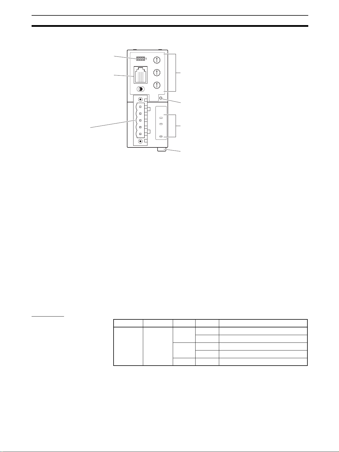
2-2 DeviceNet Communication Unit Part Names and Functions
DIP switch
E3X-MC11 Mobile Console Connector
Used to connect the Mobile Console.
When the Mobile Console is
connected, incident light level
monitoring and explicit message
communications are disabled.
Communications Connector
Connector for DeviceNet communications.
Note 1. Do not turn ON the power to the Communication Unit when the Mobile
0
NODE
ADR
1
9
2
8
3
7
4
6
5
0
1
9
2
8
3
7
4
6
5
1
3
5
1
5
13
7
11
9
Rotary switches
ON
1234
Sensor Reset Switch
Resets Sensors connected to the Unit by turning Sensor
MS
NS
SS
power OFF and ON again.
Indicators
Power Supply Connector
The E3X-DRT21 is supplied power from the Communications
Connector, so there is no power supply cable.
Console is connected. Communicat ions will not be established with the
Sensors if th e Mobile Co nsole is al read y co nnecte d when the Unit power
is turned ON.
2. Always set the Sensors to RUN mode when using the Fiber Amplifier Sensor Communication Uni t for DeviceNet. When ot her m odes ( SET or AD J)
are set, the Fiber Amplifier Sensor Communication Unit cannot read or
write Sensor data.
3. A Sensor communicati ons error will occur un der the following conditions
after the Mobile Console is connected with it’s power turned ON.
• When the power to the Mobile Console is turned OFF.
• When the Mobile Console is left idle while connected, causing the
power to automatically turn OFF.
• When the Mobile Console battery goes low, causing the power to turn
OFF.
Do not allow the above conditions to occur when using the Mobile Console,
or use the Mobile Consol e when problems wi ll not o ccur even if a Sensor
communications error occurs.
Indicators The following table shows the operation of the indicators.
Indicator Name Color Status Meaning
MS Module
status
Green Lit Operating normally.
Flashing Not set.
Red Lit A fatal error has occurred.
Flashing A non-fatal error has occurred.
--- Not lit The power is OFF.
17
Page 29

DeviceNet Communication Unit Part Names and Functions Section 2-2
Indicator Name Color Status Meaning
Normal Status of
Indicators
NS Network
status
SS Sensor
communications status
MS Operation is normal when the MS indicator is lit green.
NS Operation is normal when the NS indicator is lit green
(online and communications connected).
SS Sensors are communicating when the SS indicator is lit green.
Green Lit DeviceNet is online and communica-
tions are connected.
Flashing DeviceNet is online and communica-
tions are not connected.
Red Lit A fatal DeviceNet communications
error has occurred.
Flashing A non-fatal DeviceNet communica-
tions error has occurred.
--- Not lit DeviceNet is offline or power is OFF.
Green Lit Unit is communicating with Sensors.
Red Lit A Sensor communications error has
occurred.
--- Not lit Sensor communications are on
standby or power is OFF
Switches
Rotary Switches
DIP Switch
0
1
9
2
8
3
X10
7
4
6
5
0
1
9
2
8
3
7
4
6
5
1
3
15
5
13
7
11
9
DeviceNet Node Address Setting
Set the DeviceNet node address to between 00 and 63.
X1
(64 to 99 are not used.)
Connected Number of Sensors Setting
Registers the number of Sensors connected. By setting the number of Sensors, errors
can be detected in the configuration.
When the DIP switch pin 3 is turned ON, however, this rotary switch is disabled. Instead,
the values set from the DeviceNet Configurator or using explicit messages are enabled.
Note Fiber Amplifier Units (E3X-DA6TW and E3X-DA8TW) that are allocated two unit
numbers must be counted as two Units when counting the number of connected
Sensors.
ON
1 234
Operating mode (MODE0)
Operating mode (MODE1)
Method for setting number of Sensors
Reserved for system use.
■ Pins 1 and 2: Operating Mode Setting
These pins set the operating mode. The data allocated in the master’s IN Area
depends on the operat ing mode. For fur ther details, refer to 2-5 DeviceNet
Remote I/O Communications.
Pin 1
(MODE0)
OFF OFF Remote I/O communications one-word mode 13 max.
ON OFF Remote I/O communications two-word mode 16 max.
OFF ON Remote I/O communications two-word mode
ON ON Cannot be set. ---
Pin 2
(MODE1)
Operating mode setting Number of
Sensors
16 max.
with incident light level monitoring
18
Page 30

DeviceNet Communication Unit Part Names and Functions Section 2-2
Note Fiber Amplifier Units (E3X-DA6TW and E3X-DA8TW) that are allocated two
unit numbers must be counted as two Units when counting the number of connected Sensors.
■ Pin 3: Controlling the Setting of the Number of Connected Sensors
The number of Sensors connected is registered by using either a rotary switch
or the Configurator.
When pin 3 is ON, r egi stering the number of Se ns ors i s ena bled from Configurator or by using explicit messages enabled, and the value for the number of
Sensors enabled for communications that is stored i n the inter nal memor y of
the Fiber Amplifie r Sensor Communic ation Unit is us ed. The default value in
the internal memor y is 16. This value can be changed from the DeviceNet
Configurator. The setting methods are shown in the following table.
Pin 3 Method for setting the number of Sensors
OFF Use rotary switch to register number of Sensors.
ON Use Configurator or e xp lic it mes sa ge s to regi ste r n um be r of Se ns ors.
Note When DIP switch pin 3 is ON (register ing from Configurator or using explicit
messages), pin 1 is OF F, a nd pin 2 is ON (remote I/O communi cations twoword mode with incident light level monitor ing) , the value in the i nternal memory of the F i ber A mp li fie r Se nso r Com mu nicati on Uni t for the number o f Un its
being monitored for incident light levels is used. The d efault value in the i nternal memory is 16. This value can be se t to a different value from t he number
of Sensors connected. When pin 3 is OFF (registering from rotary switch), pin
1 is OFF, and pin 2 is ON, the rotary switch setting applies to both the number
of Sensors connected and the number of Units monitoring incident light level.
■ Pin 4: Reserved for System Use
This pin must always be OFF.
Sensor Reset Switch Press this switch to reset the connected Sensors by executing power interrup-
tion processing. This switch is used in the following case.
If the number of Sensors with co mmunications enabled does not match the
number of Sensors connected , one or more Sensors may have become disconnected. The power res et switch is require d to enable the Sensors to be
reconnected properly and for communications to be reestablished between
Sensors. Tur ning OFF th e power supply would disc onnect the F iber Amplifi er
Sensor Communication Un it f ro m D eviceNet, whic h may effect the enti re s y stem. The Sensor reset switch is thus used to reestablish communications with
the Sensors.
Note The E3X-DRT21 automaticall y uses the DeviceNet baud rate of the master.
Therefore, the DIP switch is not required to set the baud rate.
19
Page 31

Operating Procedure for DeviceNet Communication Unit Section 2-3
2-3 Operating Procedure for DeviceNet Communication Unit
Step Item Details
1 Mount the Commun icatio n Un it to
the DIN Track.
2 Connect the Fiber Amplifier Units
to the Communication Unit.
3 Set the Sensors to RUN mode. Set the mode switches to RUN mode.
4 Connect the Device Net communi-
cations connector.
5 Set the rotary switches. Two
6 Set the DIP switch. Pin 1 Pin 2 Operating mode setting Number of Sensors
Mount the Unit to the DIN Track. After mounting the Fiber Amplifier Units to the
DIN Track, connect the Units to each other.
Note: To remove the Units from the DIN Track, first slide the Units apart to disconnect them, and then remove the Units from the DIN Track.
Connect the Communication Unit to the Fiber Amplifier Units by sliding the
Communication Unit until the clips on the end are aligned and a “click” sound
is heard.
Connect the Dev iceN et C omm un ications Connector.
Note: The DC po wer supply to the Comm u ni cation Unit and all Fi ber Amp lifier
Units connected to it is supplied from the DeviceNet communications power
supply (V+, V–).
upper
switches
Lower
switch
OFF OFF Remote I/O communications
ON OFF Remote I/O communications
OFF ON Remote I/O communications
Sets the DeviceNet node address (0 to 63).
Sets the number of Sensors connected to the Unit (1 to 16).
(Enabled when DIP switch pin 3 is OFF only.)
Note 1: When DIP switch pin 3 is ON, set the number of Sensors
connected using the Configurator or explicit messages.
Note 2: Fiber Amplifier Units (E3X-DA6TW, E3X-DA8TW) that are
allocated two unit numbers must be counted as two Units
when counting the number of Sensors.
connected
13 max.
one-word mode
16 max.
two-word mode
16 max.
two-word mode with incident
light level monitoring
Pin 3 Method for setting the number of Sensors.
OFF Use the rotary switch to register setting.
ON Use the Configurator or explicit mess age s to regis ter settings.
7 Turn ON the DC power supply (V+,
V– DeviceNet communications
power supply).
8 Check the indicators. MS Operating n ormally when lit green.
9 Start communication s . Remote
Disconnect the E3X-MC11 Mobile Console before turning ON the DC power
supply.
NS Operating normally when lit green
(DeviceNet online and communications connected).
SS Communicating with Sensors when lit green.
I/O
Explicit
messages
Enable the scan list in the master and change the PLC to RUN
mode.
Send explicit messages from the master.
20
Page 32

Wiring the DeviceNet Model Section 2-4
2-4 Wiring the DeviceNet Model
Wiring
Black (V–)
Blue (CAN L)
Shield
• T he following table shows the relationsh ip between the cable color s and
signals.
Color Signal Symbol
Black Communication s po wer supply negativ e sid e V–
Blue Signal low side CAN L
--- Shield S
White Signal high side CAN H
Red Co mmunications power supply positive side V+
direction
Red (V+)
Insert
direction
White
(CAN H)
Note 1. The DeviceNet communications power supply provides power to the Com-
munication Unit and all the Sens ors (Ampl ifier Units ) conne cted to i t. Select a power supply for the Com munication Unit so tha t is has sufficient
capacity for the current consumption of the Sensors.
2. The allowable current is 3 A for the DeviceNet thin cables and 8 A for the
DeviceNet thick cables. For details on calculating the power supply for the
DeviceNet system, refer to the DeviceNet Operation Manual (Cat. No.
W267).
21
Page 33

DeviceNet Remote I/O Communications Section 2-5
2-5 DeviceNet Remote I/O Communications
2-5-1 Master Word Allocations
The E3X-DRT21 data is stored in the IN Area of the DeviceNet master. Select
one of the following three operating modes using the DIP switch.
Pin 1 Pin 2 Operat ing mode setting Number of
MODE0 MODE1
OFF OFF Remote I/O communications one-word mode 13 max.
ON OFF Remote I/O communications two-word mode 16 max.
OFF ON Remote I/O communications two-word mode
with incident light level monitoring
ON ON Cannot be set. ---
The DeviceNet Configurator can be used to set the connection type. The
Fiber Amplifier Sensor Communication Unit supports bit-strobe, polling, COS,
and cyclic connect ions. Refer to Appendix C D eviceNet Connection S ettings
for details.
Sensors
16 max.
Remote I/O
Communications
One-word Mode
(Pins 1 and 2 OFF)
Up to 13 Sensors can be connected in t his mode. One word is alloc ated to
each Sensor in the IN Area o f the master. Fiber Amplifier Units are aut omatically assigned unit numbers in ascending order starting from the Communication Unit (left side).
Bit Contents
00 Unit 1 ON/OFF data
01 Unit 2 ON/OFF data
02 Unit 3 ON/OFF data
03 Unit 4 ON/OFF data
04 Unit 5 ON/OFF data
05 Unit 6 ON/OFF data
06 Unit 7 ON/OFF data
07 Unit 8 ON/OFF data
08 Unit 9 ON/OFF data
09 Unit 10 ON/OFF data
10 Unit 11 ON/OFF data
11 Unit 12 ON/OFF data
12 Unit 13 ON/OFF data
13 Mobile Console Communications Flag
14 Sensor Communications Error Flag
15 Sensor Communications Flag
■ Mobile Console Communications Flag
Bit 13 turns ON when the Mobile Console is connected to the Communication
Unit. When the Mobile Console i s connected, the DeviceNet Configurator or
explicit message communications cannot be used to perform setting and
monitoring operations.
22
■ Sensor Communications Error Flag
Bit 14 turns ON when the reg istered number of Sen sors does not matc h the
number of Sensors that are enabled to communicate, or when a communications error occurs af ter commun ications h ave been established with the Sensors.
Page 34

DeviceNet Remote I/O Communications Section 2-5
■ Sensor Communications Flag
Bit 15 turns ON when communications are established with the Sensors.
Remote I/O
Communications
Two-word Mode
(Pin 1 ON, Pi n 2
OFF)
Up to 16 Sensors can be c onnected in t his mode. Two words are alloca ted to
each Sensor in the IN Area of the master.
Word m
Bit Contents
00 Unit 1 ON/OFF data
01 Unit 2 ON/OFF data
02 Unit 3 ON/OFF data
03 Unit 4 ON/OFF data
04 Unit 5 ON/OFF data
05 Unit 6 ON/OFF data
06 Unit 7 ON/OFF data
07 Unit 8 ON/OFF data
08 Unit 9 ON/OFF data
09 Unit 10 ON/OFF data
10 Unit 11 ON/OFF data
11 Unit 12 ON/OFF data
12 Unit 13 ON/OFF data
13 Unit 14 ON/OFF data
14 Unit 15 ON/OFF data
15 Unit 16 ON/OFF data
Word m+1
Bit Contents
00
01
02
03
04
05 Method for setting number of Sensors
06 Always 0.
07 Always 0.
08
09
10
11
12
13 Mobile Console Communications Flag
14 Sensor Communications Error Flag
15 Sensor Communications Flag
Number of Sensors connected, 2
Number of Sensors connected, 2
Number of Sensors connected, 2
Number of Sensors connected, 2
Number of Sensors connected, 2
Number of Sensors that can communicate, 2
Number of Sensors that can communicate, 2
Number of Sensors that can communicate, 2
Number of Sensors that can communicate, 2
Number of Sensors that can communicate, 2
0
1
2
3
4
0
1
2
3
4
■ Number of Sensors Connected
Bits 00 to 04 give the number of Sensors that are currently registered
between 1 and 10 Hex (1 to 16 decimal).
23
Page 35

DeviceNet Remote I/O Communications Section 2-5
■ Switching Method for Setting Number of Sensors Connected
Bit 05 gives the status of DIP switch pin 3, which c ontrols the method for registering the number o f Sen so rs conne cted. When this bit is OF F, pin 3 is OFF,
and when the bit is ON, pin 3 is ON.
■ Number of Sensors That Can Communicate
Bits 08 to 12 give the number of S ensors tha t are curr ently able to c ommunicate between 1 and 10 Hex (1 to 16 decimal). This setting enables the user to
check how many Sensors are communicating normally when an error occurs.
■ Mobile Console Communications Flag
Bit 13 turns ON when the Mobile Console is connected to the Communication
Unit. When the Mobile Console is connected, the Configurator or explicit message communications cannot be used to perform setting and monitoring operations.
■ Sensor Communications Error Flag
Bit 14 turns ON when the number o f Sensors register ed as connected d oes
not match the number of Sensors that can communicate, or when a communications error occurs after communications have been established with the
Sensors.
■ Sensor Communications Flag
Bit 15 turns ON when communications are established with the Sensors.
Note Fiber Amplifier Uni ts (E3X-DA6TW, E3X-DA8TW) that are al located two unit
numbers are allocated two bits of ON/OF F data an d are counted as two Units
when counting the number of Sensors.
24
Page 36

DeviceNet Remote I/O Communications Section 2-5
Remote I/O
Communications
Two-word with
Incident Light
Level Monitoring
Mode (Pin 1 OFF,
Pin 2 ON)
Up to 16 Sensors can be connected in this mode. The incident light level monitor default setting is to monit or all the Se ns or s th at are c onn ec ted. B y tu rning
ON pin 3 of the DIP switch, the number of S ensors being m onitored for incident light levels can be changed from the DeviceNet Confi gurator or by using
explicit messages.
When the number of Senso rs to be m onitor ed is set, the i ncide nt light l evel is
monitored star ti ng from the Uni t next to the Fiber Amp lifie r Sensor Com munication Unit up to the number of Sensors that is current set.
In addition to word m and word m+1, one word i s allocated in the IN Area of
the master for each Sensors to be monitored for incident light level.
Word m
Bit Contents
00 Unit 1 ON/OFF data
01 Unit 2 ON/OFF data
02 Unit 3 ON/OFF data
03 Unit 4 ON/OFF data
04 Unit 5 ON/OFF data
05 Unit 6 ON/OFF data
06 Unit 7 ON/OFF data
07 Unit 8 ON/OFF data
08 Unit 9 ON/OFF data
09 Unit 10 ON/OFF data
10 Unit 11 ON/OFF data
11 Unit 12 ON/OFF data
12 Unit 13 ON/OFF data
13 Unit 14 ON/OFF data
14 Unit 15 ON/OFF data
15 Unit 16 ON/OFF data
Word m+1
Bit Contents
00
01
02
03
04
05 Method for setting number of Sensors
06 Always 0.
07 Always 0.
08
09
10
11
12
13 Mobile Console Communications Flag
14 Sensor Communications Error Flag
15 Sensor Communications Flag
Number of Sensors connected, 2
Number of Sensors connected, 2
Number of Sensors connected, 2
Number of Sensors connected, 2
Number of Sensors connected, 2
Number of Sensors that can communicate, 2
Number of Sensors that can communicate, 2
Number of Sensors that can communicate, 2
Number of Sensors that can communicate, 2
Number of Sensors that can communicate, 2
0
1
2
3
4
0
1
2
3
4
25
Page 37

DeviceNet Remote I/O Communications Section 2-5
15 14 13 12 11 10 09 08 07 06 05 04 03 02 01 00
Word m + 2 Unit 1 incident light level
Word m + 3 Unit 2 incident light level
Word m + 4 Unit 3 incident light level
:
:
Word m + n Unit n – 1 incident light level
Word m + n + 1 Unit n incident light level
Number of Sensors for incident light level monitoring: n
Note 1. Wh en the number of Se nsors for incident li ght level monitoring is greater
than the value set for the number of Sensors conne cted for communications, the incident light level for the Sensors that are not connected will be
0000.
2. When the Mobile Console is connected, the incident light level data cannot
be read and the data will be 7FFF.
3. When an error occur s in communic ations with Sen sors, the incide nt light
level data for the Sensors not communicating will be 7FFF.
4. The incident light level data for the E39-TM1 Te rmin al Block Units will be
7FFF. Monitoring incident light levels for Terminal Block Units causes a delay in the data refresh cycle. To speed up the refresh cycle, mount the Terminal Block Unit to the farthe st position from the Fiber Amplif ier Sensor
Communication Unit, and use th e Devi ceNet Configurator or an explicit
message to set the number of devices to be monitored for incident light level requirement so that the Terminal Block Unit is not monitored.
5. The refresh timing of Sen sor ON/OF F data and i ncide nt light level data is
not synchronized. Even if incident light level data is read whi le monitoring
the ON/OFF status, the incident light level data may not be indicated for the
ON and OFF status. To re ad inciden t light level data at ON and OFF, use
the E3X-DA6-P Sensor. For details on this Sensor, refer to Appendix B
Monitoring Incident Light Levels of E3X-DA6-P Sensors.
:
:
26
Page 38

Explicit Message Communications Section 2-6
2-6 Explicit Message Communications
Sending DeviceNet explicit messages from the m aster to the Communi cation
Unit enables reading or writi ng any parameters of Fiber Amplifier Un its. The
Communication Unit processes the command sent from the master and
returns a response.
2-6-1 Basic Format of Explicit Messages
The basic formats of command and response blocks are shown here.
Command Block
Destination
node
address
Destination Node A ddress
Specifies the node addr ess of the Unit to which the explicit message (command) is to be sent as a 1-byte hexadecimal value.
Service Code, Class ID, Instance ID, Attribute ID
Specify the command ty pe, the Unit to receive the com mand, and other processing details. The Fiber Amplifier Sensor Communication Unit uses the
instance ID to s pec ify to S en so rs for whic h the co mm and is i nte nde d ( S ens or
unit number). Some commands do not require an attribute ID.
Note The number of bytes specifi ed for the class ID, instance ID, and at-
Service
Code
Class ID Instance ID Attribute ID Data
tribute ID depend on the master used. When the command is sent
from an OMRON DeviceNet Unit (master), the class ID and instance
ID are specified a s 2 bytes (4 digits ) each , and the attri bute ID as 1
byte (2 digits).
Data
Data is not required for the READ command.
Response Block Normal Block
Number of
received
bytes
Error Block
Number of
received
bytes fixed
at 0004 Hex
Number of Received Bytes
The number of data bytes received starti ng from the source node is retur ned
as a hexadecimal value. When an error response is returned to an explicit
message, this value will be 0004 Hex.
Source Node Address
Returns the node ad dress of th e node from whic h the comma nd was sent as
a hexadecimal value.
Source node
address
Source node
address
Service
Code
Service
Code
Data
Error Code
27
Page 39

Explicit Message Communications Section 2-6
Service Code
When the command is complete d normall y, the value speci fied in the command with leftmost bit of the service code turned ON is stored as shown in the
following table.
Command service code Response service code
10 Hex 90 Hex
0E Hex 8E Hex
16 Hex 96 Hex
06 Hex 86 Hex
07 Hex 87 Hex
05 Hex 85 Hex
When an error respo nse is ret urned to an explicit message, this value wil l be
94 Hex.
Data
Used to store read data only when a READ command has been sent.
Error Code
Specifies the explicit me ssage error code. For details, refer to 2-6-5 List of
Error Codes.
Note Set t he DeviceNet message mon itoring timer in the Fiber Amplifier Sensor
Communication Unit to 6 s minimum.
The procedure for setting the timer is as follows:
Using a CS1W-DRM21 or CJ1W-DRM21
Use the following procedure to set the timer from the DeviceNet Configurator.
1,2,3... 1. Place the Configurator online by selecting Network and Connection.
2. Select and double-click either CS1W-DRM21 or CJ1W-DRM21.
3. Set the Fiber Amplifier Sensor Communication Unit node monitoring timer
to 6,000 ms.
28
Page 40

Explicit Message Communications Section 2-6
4. Set the response monitoring time to 6,000 ms minimum using the
CMND(490) instruction to send an explicit message.
Using C200HW-DRM21 or CVM1-DRM21
Set the response m onitoring time to 6,000 ms using the IOWR(223) instruction to send an explicit message. (The message monitoring timer does not
need to be set with the DeviceNet Configurator.)
2-6-2 READ Command
The READ command i s used to read data from the Fiber Ampl ifier Sensor
Communication Unit or the Sensors conn ected to it. W hen an OMRON master is used, the formats of the command and response blocks are as follows:
Command Block
Destination
node
address
1 byte 1 byte 2 bytes 2 bytes 1 byte
Service
Code Class ID
0E fixed
Response Block Normal Format
No. of received bytes
0004 (See note.)
2 bytes
Note The bytes of read data for Batch Read Incident Light Levels and Batch Read
Threshold Settings is twice the number of Sensors being read. The number of
received bytes is two plus twice the number of Sensors being read.
Error Format
No. of received bytes
Destination
node
address
Destination
node
address
Service Code
8E fixed
1 byte1 byte
Service Code
94 fixed0004
Instance ID
Read data
2 bytes (See note.)
Error Code
Attribute ID
List of READ
Commands
2 bytes
1 byte 1 byte 2 bytes
The following table lists the explicit message READ commands.
Explicit message Function Command
Class IDInstance IDAttribute
Read ON/OFF Data Reads the ON/OFF status of
connected Sensors
Read Status Reads the status of the
Read Incident Light
Level
Batch Read Incident
Light Levels
Fiber Amplifier Sensor Communication Unit
Specifies the unit number as
the instance ID and reads
the incident light level.
Reads incident l ight le vel s of
connected Sensors in a
batch.
009C 0000 01
009C 0000 02
009C Unit
number
009C 0000 67
ID
03
29
Page 41

Explicit Message Communications Section 2-6
Explicit message Function Command
Read ON Incident Light
Level
(See note 2.)
Read OFF Incident
Light Level
(See note 2.)
Batch Read ON Incident Light Levels
(See note 2.)
Batch Read OFF Incident Light Levels
(See note 2.)
Read Threshold Setting Specifies the unit number as
Batch Read Threshold
Settings
Read Basic Settings Specifies the unit number as
Read Timer Setting Specifies the unit number as
Read Hysteresis Width Specifies the unit number as
Read Custom Flags Specifies the unit number as
Read Special Flags
(See note 3.)
Read Number of Sensors
Read Number of Incident Light Le vel Moni tor
Units
Specifies the unit number as
the instance ID and reads
the incident light l ev els when
Sensor is ON.
Specifies unit number as the
instance ID and reads the
incident light level when
Sensor is OFF.
Reads the ON incident light
levels of connected Sensors in a batch.
Reads the OFF incide nt light
levels of connected Sensors in a batch.
the instance ID and reads
the threshold value.
Reads the threshold values
of the connected Se ns ors in
a batch.
the instance ID and reads
basic settings .
the instance ID and reads
the timer.
the instance ID and reads
the hysteresis width.
the instance ID and reads
the Custom Flags.
Specifies the unit number as
the instance ID and reads
the Special Flags.
Reads the number of Sensors connected.
Reads the number of Units
monitoring incident light levels.
Class IDInstance IDAttribute
009C Unit
number
009C Unit
number
009C 0000 68
009C 0000 69
009C Unit
number
009C 0000 75
009C Unit
number
009C Unit
number
009C Unit
number
009C Unit
number
009C Unit
number
009C 0000 30
009D 0000 31
ID
04
05
11
12
13
16
17
1C
30
The unit number specifie d by the instanc e ID must be set be tween 0001 Hex
and 0010 Hex.
Note 1. The E39-TM1 Terminal Block Unit has no parameters that can be read, so
an error will occur if the unit number of a Terminal Block Unit is specified.
2. An error will occur if the (Batch) Read ON/OFF Incident Light Levels command is executed when the unit number of a Unit other than an E3X-DA6P is specified.
3. An error will occur if t he Read Spec ial Flags c ommand is executed when
the unit number o f a Unit other than an E3X-DA6TW or E3X-DA8TW is
specified.
The following tables and explanations provide the data format for each item.
Page 42

Explicit Message Communications Section 2-6
Read ON/OFF Data
Bit Contents
00 Unit 1 ON/OFF data
01 Unit 2 ON/OFF data
02 Unit 3 ON/OFF data
03 Unit 4 ON/OFF data
04 Unit 5 ON/OFF data
05 Unit 6 ON/OFF data
06 Unit 7 ON/OFF data
07 Unit 8 ON/OFF data
08 Unit 9 ON/OFF data
09 Unit 10 ON/OFF data
10 Unit 11 ON/OFF data
11 Unit 12 ON/OFF data
12 Unit 13 ON/OFF data
13 Unit 14 ON/OFF data
14 Unit 15 ON/OFF data
15 Unit 16 ON/OFF data
Read Status
Bit Contents
00
01
02
03
04
Number of Sensors connected, 2
Number of Sensors connected, 2
Number of Sensors connected, 2
Number of Sensors connected, 2
Number of Sensors connected, 2
05 Method for setting number of Sensors
06 Always 0.
07 Always 0.
08
09
10
11
12
Number of Sensors that can communicate, 2
Number of Sensors that can communicate, 2
Number of Sensors that can communicate, 2
Number of Sensors that can communicate, 2
Number of Sensors that can communicate, 2
13 Mobile Console Communications Flag
14 Sensor Communications Error Flag
15 Sensor Communications Flag
0
1
2
3
4
0
1
2
3
4
■ Number of Sensors Connected
Bits 00 to 04 give in hexadecimal the number of Se nsors that are currently
registered.
■ Switching Method for Setting Number of Sensors Connected
Bit 05 gives the status of DIP switch pin 3, which c ontrols the method for registering the num ber of Sensors c onnected. Whe n this bit is s et OFF, pin 3 is
OFF, and when the bit is ON, pin 3 is ON.
31
Page 43

Explicit Message Communications Section 2-6
■ Number of Sensors That Can Communicate
Bits 08 to 12 give the number of S ensors tha t are curr ently able to c ommunicate in hexadecimal. This se tting enables the user to check how many Sensors are communicating normally when an error occurs.
■ Mobile Console Communications Flag
Bit 13 turns ON when the Mobile Console is connected to the Communication
Unit. When the Mobile Console is connected, explicit message communications cannot be used.
■ Sensor Communications Error Flag
Bit 14 turns ON when the number o f Sensors register ed as connected d oes
not match the number of Sensors that can communicate, or when a communications error occurs after communications have been established with the
Sensors.
■ Sensor Communications Flag
Bit 15 turns ON when communications are established with the Sensors.
Read (ON/OFF) Incident
Light Level
Batch Read (ON/OFF)
Incident Light Levels
Reads the incident light level of the Sensor for the unit number specified in the
instance ID. The data is given as a 2-byte (4-digit) hexadecimal value, and
negative data is expressed as its two’s complement.
Data for the Read ON/OFF Incident Light Level commands can be read when
using an E3X-DA6-P Sensor only. For details on ON/OF F in ci den t lig ht levels,
refer to Appendix B Monitoring Incident Light Levels of E3X-DA6-P Sensors.
Reads as a batch the Sensor data sta rting from un it numb er 1 for the number
of Sensors specified a s con nected . The da ta is given as hexadecim al values,
with 16 bits of data for each Unit. Negative data is expressed as its two’s complement.
Unit number 1
incident light level
Units numbers specified as number of connected Sensors: N Units
Unit number 2
incident light level
Unit number N + 1
incident light level
Unit number
N incident
light level
The Batch Read Inci dent Light Level command ca nnot be used w hen one or
more E39-TM1 Te rminal Block Units is connected.
Data for the Batch Read ON/OFF Incident Light Level commands can be read
only if all Sensor s are E3 X-DA6-P Sensors. Th e comman d ca nnot be u sed if
one or more Sensors other than E3X-DA6-P Sensors are connected. For
details on ON/OFF incident light levels, refer to Appendix B Monitor ing Inci-
dent Light Levels of E3X-DA6-P Sensors.
Read Threshold Setting Reads the threshol d setting of the Senso r for the unit number spe cifie d in the
instance ID. The data is given as a 2-byte (4-digit) hexadecimal value, and
negative data is expressed as its two’s complement.
Batch Read Threshold
Settings
Reads as a batch the Sensor data sta rting from un it numb er 1 for the number
of Sensors specified a s con nected . The da ta is given as hexadecim al values,
with 2 bytes (4 digits ) of da ta for each Unit. Negative dat a is expressed as its
two’s complement.
Unit number 1
threshold setting
Units numbers specified as number of connected Sensors: N Units
Unit number 2
threshold setting
Unit number N – 1
threshold setting
Unit number
N threshold
setting
32
Page 44

Explicit Message Communications Section 2-6
This command cannot be us ed if one or mo re E39-TM1 Terminal Block Units
is connected.
Read Basic Settings Reads the basic sett ings of the Sensor for the unit number specified in the
instance ID. The data contents are as follows:
Bit Contents
00 Display Contents:
01
02 Display Orient ation:
03 Hold Setting:
04
05 Flashing Setting:
06 Sensing Setting:
07
08 Timer Mode:
09
10 Number of Display Digits:
11
12
13 Always 0.
14 Tea ching during RUN
15 Eco Mode
0: Digital incident level
1: Digital percentage
2: Analog incident level
0: Standard
1: Reversed
0: OFF
2: Peak
3: Bottom
0: OFF
1: ON
0: Standard
2: Super long-distance
3: Super high-speed
1: OFF-delay
2: ON-delay
3: One-shot
0: 4 digits
1: 3 digits
2: 2 digits
3: 1 digit
4: 0 digits
0: OFF
1: ON
0: OFF
1: ON
Read Timer Settings Reads the OFF-delay, O N-delay, and o ne-shot timers of the Sensor for the
unit number specified in the instance ID. The data is given as a 2-byte (4-digit)
hexadecimal value. The value is given in ms.
33
Page 45

Explicit Message Communications Section 2-6
Read Hysteresis Width Reads the hysteresis wid th of the S ensor for the uni t number spec ified i n the
instance ID. The data is given as a 3-digi t hexadecimal value. Bits 14 and 1 5
are used to display the sensing setting.
Bit Contents
00 to 11 Hysteresis Width
12 Always 0.
13 Always 0.
14 Sensing Setting:
15
Read Custom Flags Reads whether the following s ett ing s for the Sens or o f th e u nit number speci-
fied in the instance ID can be set or monitored from the sensor key switch.
Bit Contents
00 Hold Setting:
01
02 Flashing Setting:
03
04 OFF-delay Timer Setting:
05
06 Sensing Setting:
07
08 Sensitivity Adjustment:
09 Teaching:
10 Display Contents:
11 Zero Reset:
12 Monitor Foc us Ran ge:
13
14 Display Orient ation:
15
0: Standard
2: Super long-distance
3: Super high-speed
0: Enable
1: Not displayed
2: Disable
0: Enable
1: Not displayed
2: Disable
0: Enable
1: Not displayed
2: Disable
0: Enable
1: Not displayed
2: Disable
0: Enable
1: Disable
0: Enable
1: Disable
0: Enable
1: Disable
0: Enable
1: Disable
0: Enable
1: Not displayed
2: Disable
0: Enable
1: Not displayed
2: Disable
34
Page 46

Explicit Message Communications Section 2-6
Read Special Flags Reads the status of the following settings for the Sensor of the unit number
specified in the instanc e ID. This command is possible with E3X-DA6TW and
E3X-DA8TW Sensors only. Executing this command for any other sensor will
cause an error to occur.
Bit Contents
00 0 or 1
01 0 or 1
02 Always 0.
03 Always 0.
04 Operating Mode Flag (one-word):
0: Dark-ON
1: Light-ON
05 Operating Mode Flag (two-word):
0: Dark-ON
1: Light-ON
06 Area Setting Flag:
0: AREA OFF
1: AREA ON
07 0 or 1
08 Always 0.
09 Always 0.
10 Always 0.
11 Always 0.
12 Always 0.
13 Always 0.
14 Always 0.
15 Always 0.
Note Bits 00, 01, and 07 are read as 0 or 1 accor ding to the inter nal status of th e
Sensor.
Read Number of Sensors Reads the number o f Sensors that are connecte d. The data is given as a 2-
byte (4-digit) hexadecimal value. When pi n 3 is O N (r egistrati on usi ng explicit
messages or Configurator), the values from the internal memory are read,
and when pin 3 is OFF (r egistration usin g rotar y switch), the setting fro m the
rotary switch is read. The data range is from 0001 Hex to 0010 Hex.
Read Number of Light
Level Monitoring Units
Reads the number of Units monitoring incident light levels when using twoword mode with incident light level monitoring (i.e., when DIP switch pins 1
and 2 are OFF). Th e data is given as a 2-byte (4-digit) hexadecimal value.
When pin 3 is ON, the values from the inter nal memor y are read, and when
pin 3 is OFF, the values from the rotary switch are read. The data range is
from 0000 Hex to 0010 Hex.
35
Page 47

Explicit Message Communications Section 2-6
2-6-3 WRITE Command
The WRITE command is used to write data to the Fiber Amplifier Sensor
Communication Unit or the Sensors conn ected to it. W hen an OMRON master is used, the formats of the command and response blocks are as follows:
Command Block
Destination
node
address
Service
Code
10 (fixed)
Class ID Instance ID
Attribute ID Write data
1 byte
1 byte
Response Block Normal Format
Number of received
bytes
0002 (fixed)
2 bytes 1 byte 1 byte
Error Format
Number of
received bytes
0004
2 bytes 1 byte 1 byte 2 bytes
List of WRITE
Commands
The following table lists the explicit message WRITE commands.
Explicit message Function Command
Write Th reshold Se tting
Write Basic Settings Specifies the unit number as
Write Timer Setting Specifies the unit number as
Write Hysteresis
Width
Write Custom Flags Specifies the unit numbe r as
Write Special Flags Specifies the unit number as
Write Number of Sensors
Write Number of Light
Level Monitor Units
2 bytes
Destination
node
address
90 (fixed)
Destination
node
address Service Code
Specifies the unit number as
the instance ID and writes
threshold value.
the instance ID and writes
basic settings.
the instance ID and writes
timer.
Specifies the unit number as
the instance ID and writes hysteresis width.
the instance ID and writes
Custom Flags.
the instance ID and writes
Special Flags.
Writes t he number of Sensors
connected.
Writes t he number of Units
monitoring incident light levels.
Service
Code
94 (fixed)
1 byte2 bytes
Error Code
Class IDInstance IDAttribute
009C Unit
number
009C Unit
number
009C Unit
number
009C Unit
number
009C Unit
number
009C Unit
number
009C 0000 30
009D 0000 31
2 bytes
ID
11
12
13
16
17
1C
36
Page 48

Explicit Message Communications Section 2-6
Note 1. The un it number specified by the in stance ID must be set bet ween 0001
Hex and 0010 Hex.
2. An error will occur if the unit number of an E39-TM1 Terminal Block Unit is
specified.
3. When WRITE commands a re executed, the settings are w ritten to the internal memory . The number of times that data can be written to the internal
memory is limited. The internal memory may be corrupted if more than one
million (1,000,000) write operations are performed for each Sensor and parameter. Therefore, when using WRITE comman ds, be sure to create a
communications program th at prevents the number of writing operations
from exceeding one million (1,000,000) for each Sensor and parameter.
4. Do not send commands for attribute ID that are not specified. Accidentally
sending such commands may overwrite internal parameters. If the internal
parameters of a con nected Sensor are overwrit ten, execute the Initialize
Sensor Settings ope ration command . If the inter na l parameters of the Fiber Amplifier Sensor Communication Unit are overwritten, write 0000 Hex
for the following attribute ID settings to clear them.
Explicit message Command
Class ID Instance ID Attribute ID
Internal paramete r 1 009D 0000 32
Internal paramete r 2 009D 0000 33
The following explanations provide the data format for each item.
Write Threshold Setting Writes the thresho ld sett ing of th e Sens or for the unit number spec ified in th e
instance ID to the Sensor’s internal me mory. The data is given as a 2-byte (4digit) hexadecimal value, and n egative data is expressed as i ts two ’s complement.
Note 1. The Write Threshold Setting command cannot be executed when the Zero
Reset setting is enabled. Disable Zero Reset to execute the Write Threshold Setting command.
2. The setting range of Write Threshold Setting command changes when the
Write Hysteresis Width command is executed. An error will occur if the value written is outside the setting range.
Write Basic Settings Sets the basic settings of the Sensor for the unit number specified in the
instance ID. The data contents is shown in the following table.
Bit Contents
00 Display Contents:
01
02 Display Orient ation:
03 Hold Setting:
04
0: Digital incident level
1: Digital percentage
2: Analog incident level
0: Standard
1: Reversed
0: OFF
2: Peak
3: Bottom
37
Page 49

Explicit Message Communications Section 2-6
Bit Contents
05 Flashing Setting:
0: OFF
1: ON
06 Sensing Setting:
07
08 Timer Mode:
09
10 Number of Display Digits:
11
12
13 Always 0.
14 Tea ching during RUN
15 Eco Mode
0: Standard
2: Super long-distance
3: Super high-speed
1: OFF-delay
2: ON-delay
3: One-shot
0: 4 digits
1: 3 digits
2: 2 digits
3: 1 digit
4: 0 digits
0: OFF
1: ON
0: OFF
1: ON
Write Timer Setting Wr ites the timer setting for the OFF-de lay, ON-del ay, o r one-sh ot timer of the
Sensor for the unit number specified in the instance ID. The data is given as a
2-byte (4-digit) hexadecimal value. The value is set in ms. The setting range is
0000 Hex to 00C8 Hex, but the possible settings are restricted as follows:
Timer setting Setting interval
0 to 20 ms 1-ms increments
20 to 200 ms 5-ms increments
An error will o ccur if a value is wri tten that does not mee t the above setting
interval conditions.
Write Hysteresis Width Writes the hysteresis width of the Senso r for the unit number specified in the
instance ID. The data is given as a 2-byte (4-digit) hexadecimal value.
Write Custom Flags Set whether the following se ttings for the Senso r of the un it number spe cifie d
in the instance ID can be set or monitored from the sensor key switch.
Bit Contents
00 Hold Setting:
01
02 Flashing Setting:
03
0: Enable
1: Not displayed
2: Disable
0: Enable
1: Not displayed
2: Disable
38
Page 50

Explicit Message Communications Section 2-6
Bit Contents
04 OFF-delay Timer Setting:
05
06 Sensing Setting:
07
08 Teaching:
09 Sensitivity Adjustment:
10 Zero Reset:
11 Display Contents:
12 Monitor Foc us Ran ge:
13
14 Display Orient ation:
15
0: Enable
1: Not displayed
2: Disable
0: Enable
1: Not displayed
2: Disable
0: Enable
1: Disable
0: Enable
1: Disable
0: Enable
1: Disable
0: Enable
1: Disable
0: Enable
1: Not displayed
2: Disable
0: Enable
1: Not displayed
2: Disable
Write Special Flags Writes the following settin gs for the Sensor of the unit numbe r sp ec ifi ed in the
instance ID. This command is possible with E3X-DA6TW and E3X-DA8TW
Sensors only. Writing this command for any other sensor will cause an error.
Bit Contents
00 Always 0.
01 Always 0.
02 Always 0.
03 Always 0.
04 Operating Mode Flag (one-
05 Operating Mode Flag (two-
06 Area Setting Flag:
07 Always 0.
08 Always 0.
09 Always 0.
word):
0: Dark-ON
1: Light-ON
word):
0: Dark-ON
1: Light-ON
0: Area OFF
1: Area ON
39
Page 51

Explicit Message Communications Section 2-6
Bit Contents
10 Always 0.
11 Always 0.
12 Always 0.
13 Always 0.
14 Always 0.
15 Always 0.
Write Number of Sensors Writes to the Fiber Ampl ifier Sensor Communication Unit’s intern al memory
the number of Se ns ors th at ar e conn ect ed. An er ror will occu r if th is comma nd
is executed when pin 3 is OFF. The data is given as a 2-byte (4-digit) hexadecimal value between 0001 Hex and 0010 Hex. The default setting is 16 Sensors.
Write Number of Light
Level Monitor Units
Writes to the Fib er Amplifier Sensor Communicat ion Unit’s intern al memory
the number of Units to be m onitored for incident light levels when using twoword mode with incident ligh t leve l monitoring (DIP switch pin 1 OFF and 2
ON). When pin 3 is ON, t he value that was written for the number of Units t o
be monitored for incident lig ht levels is enabled. The d ata is gi ven as a 2-byte
(4-digit) hexadecimal value between 0000 Hex and 0010 Hex. The default setting is 16 Units.
2-6-4 Operation Commands
Executes teaching and other operations for the Sensors connected to the
Communication Unit. When an OMRON master is used, the formats of the
command and response blocks are as follows:
Command Block
Response Block Normal Format
Destination
node
address
1 byte 1 byte
Number of
received bytes
0002
Service
Code
Class ID
009C (fixed)
2 bytes
Destination
node
address
Service
Code
90 (fixed)
Instance ID
2 bytes
Operation
data
1 byte
40
2 bytes
Error Format
Number of received
bytes
0004
2 bytes 1 byte 1 byte 2 bytes
1 byte
Destination
node
address
1 byte
Service
Code
94 (fixed)
Error Code
Page 52

Explicit Message Communications Section 2-6
List of Operation
Commands
The following table lists the explicit messages operation commands.
Explicit
message
Adjust Maximum Sensitivity
Teach One
Point
Teach First
Point
Teach Second
Point
Teach First
Position
Teach Second
Position
Start Zero
Reset
Start Flashing Specifies the unit number as the
Disable Zero
Reset
Stop Flashing Specifies the unit number as the
Initialize Sensor
Settings
Reset When the command is sent, all
Specifies the unit number as the
instance ID, and sets the maximum sensitivity when the command is sent.
Specifies the unit number as the
instance ID, and teaches one
point when the command is sent.
Specifies the unit number as the
instance ID, and teaches the first
point of two-point teaching when
the command is sent.
Specifies the unit number as the
instance ID, and teaches the second point of two-point teaching
when the command is sent.
Specifies the unit number as the
instance ID, and teaches the first
position when the command is
sent.
Specifies the unit number as the
instance ID, and teaches the second position when the command
is sent.
Specifies the unit number as the
instance ID, and starts the zero
reset operation when the command is sent.
instance ID, and starts flashing
when the command is sent.
Specifies the unit number as the
instance ID, and disables the
zero reset operation when the
command is sent.
instance ID, and stops flashing
when the command is sent.
Specifies the unit number as the
instance ID, and resets all the
Sensor internal settings to the
default settings when the command is sent.
the connected Sensors are reset
by turning the power OFF and
then ON again.
Function Command
Service
code
16 Unit
16 Unit
16 Unit
16 Unit
16 Unit
16 Unit
06 Unit
16 Unit
07 Unit
07 Unit
05 Unit
05 00 None
Instance IDOperation
number
number
number
number
number
number
number
number
number
number
number
command
data
30
31
32
33
34
35
50
53
60
63
None
1. The unit number specified by the Instance ID must be set to between 0001
Hex and 0010 Hex.
2. An error will occur if the unit number of an E39-TM1 Terminal Block Unit is
specified.
41
Page 53

Explicit Message Communications Section 2-6
3. An error will occur when performing two-point teaching or two-position
teaching if the comma nd for the second poi nt is se nt without sen ding the
command for the first point/position. Send the command for the first point/
position before sending the command for the second one.
4. The Initialize Sensor Settings command will retur n the settings for each
Sensor to its default value. The Sensor Reset command interrupts the
power by turning the Sensor power OFF and ON again.
2-6-5 List of Error Codes
Response
codes
08FF Service not supported There is an error in the service code.
09FF Invalid attribute value The specified attribute ID is not supported.
16FF Object does not exist The specified instance ID is not supported.
15FF Too much data Size of data is longer than specified size.
13FF Not enough data Size of data is shorter than specified size.
0CFF Object state conflict Specified command cannot be executed.
20FF Invalid parameter The specified operation data is not supported.
0EFF Attribute not settable A write service code was specified for a read-only attribute ID.
Error name Cause
The write data is outside the data range.
•Threshold setting is outside setting range.
•Basic settings are outside setting range.
•Timer is not set according to restrictions.
•Hysteresis width is set outside range.
•Custom Flags are set outside range.
• Special Flags are set outside range.
• Number of Sensors connected is not set between 1 and 16.
•Number of Units monitoring incident light are not set between 1 and 16.
• Number of Units specified in instance ID is greater than number of Sensors
connected.
• Mobile Console is connected.
•Error has occurred in communications with Sensor.
• Sensor is not set to RUN mode.
• The command for the second point/position of a Two-point Teaching or Two-
position Teaching commands was executed without executing the command for
the first one.
•An unsupported command was sent. (For example, a Read Incident Light Level
command was sent to a Terminal Block Unit.)
42
Page 54

Explicit Message Communications Section 2-6
2-6-6 Using Explicit Messages: Example
The following example is for sending explicit messages using a CS1WDRM21 DeviceNet Unit.
DeviceNet Unit, unit
number: 0
CMND(490)
CPU
Unit
Node address: 05
Unit address: FE Hex or 10 Hex
Fiber Amplifier Sensor
Explicit message
Operation • The threshold of the Sensor for unit number 1 connected to the Fiber
Amplifier Sensor Communication Unit is written.
• The EXPLICIT MESSAGE SEND (2801) command is used to read data.
• The command data is written starting at D01000 in the CPU Unit, and the
response data is stored starting at D02000.
• When a command is not executed properly, the end code is stored in
D00006, and the command is resent.
Communication Unit,
node address: 11
Command Details [CMND S D C]
S D01000+ 0: 2801 Hex Command code
+ 1: 0B10 Hex Fiber Amplifier Sensor Communication Unit,
node address: 11, Service code: 10 Hex
+ 2: 009C Hex Class ID: 009C Hex
+ 3: 0001 Hex Instance ID: 0001 Hex
+ 4: 11FF Hex Attribute ID: 11 Hex
and write data in rightmost byte: FF Hex
+ 5: 0700 Hex Write data in leftmost byte: 07 Hex
D D02000: First word where response stored
C D00000+ 0: 000B Hex Number of command data bytes
+ 1: 0008 Hex Number of response data bytes
+ 2: 0001 Hex Destination network address: 1
+ 3: 05FE Hex Destination node address: 5
Destination unit address: FE Hex (or 10 Hex)
+ 4: 0000 Hex Response request,
communications port No.: 0, retries: 0 Hex
+ 5: 003C Hex Response monitoring time: 6 s
Response D D02000 + 0: 2801 Hex
+ 1: 0000 Hex
+ 2: 0002 Hex
+ 3: 0B90 Hex Response source node address: 11 (0B Hex)
Normal completion: 90 Hex
43
Page 55

Explicit Message Communications Section 2-6
)
Ladder Program Example
000000
A20011
First
Cycle
Flag
㧔071㧕
BSET #0000 D00000 D02999
㧔021㧕
MOV #000B D00000
#0000 set in D00000 to D02999.
#000B set in D00000 (send data bytes: 11).
㧔021㧕
MOV #0008 D00001
㧔021㧕
MOV #0001 D00002
㧔021㧕
MOV #05FE D00003
㧔021㧕
MOV #0000 D00004
㧔021㧕
MOV #003C D00005
㧔021㧕
MOV #2801 D01000
㧔021㧕
MOV #0B10 D01001
㧔021㧕
MOV #009C D01002
㧔021㧕
MOV #0001 D01003
㧔021㧕
MOV #11FF D01004
㧔021㧕
MOV #0700 D01005
#0008 set in D00001 (receive data bytes: 8).
#0001 set in D00002 (destination network address: 01
#05FE set in D00003 (destination node address: 05,
destination unit address: FE)
#0000 set in D00004 (response required,
communications port No.: 0, retries: 0).
#003C set in D00005 (response monitoring time: 6 s)
#2801 set in D01000
(explicit command).
#0B10 set in D01001.
#009C set in D01002.
Command data
#0001 set in D01003.
#11FF set in D01004.
#0700 set in D01005.
000014
000019
000025
Execute
conditions
000000
A20200
Network
Communications
Enabled Flag
000001 A20200 A21900
Network
Communications
Enabled Flag
151100
Online status
(word n + 1,
bit 00)
Network
Communications
Error Flag
㧔021㧕
MOV #0001 0000
㧔490㧕
CMND D01000 D02000 D00000
㧔025㧕
ASL 0000
㧔021㧕
MOV A203 D00006
㧔026㧕
ASR 0000
㧔001㧕
END
#0001 set in CIO 0000.
11 bytes of command data is sent from D01000 to
destination node address 05, and 8 bytes of response
data is stored in D02000 of the local node. (D00000 is
control data).
Contents of CIO 0000 is shifted one bit to the left. (CIO
000001 turns ON)
A203 (Network Communications Response Code) is
stored in D00006.
Contents of CIO 0000 is shifted one bit to the right and
retry executed in next cycle. (CIO 000000 turns ON).
END
44
Page 56

Setting, Monitoring, and Operating Sensors from the DeviceNet Configurator Section 2-7
2-7 Setting, Monitoring, and Operating Sensors from the
DeviceNet Configurator
2-7-1 Overview
The DeviceNet Configurator (Ver. 2.10 or higher) can be used to edit and
monitor device parameters to support the following setting, monito ring, and
operating functions.
Setting and Downloading
from the Communication
Unit
Setting and Downloading
Sensor Settings
Monitoring the
Communication Unit
Sensor Operations • Adjusting the maximum sensitive
• Setting the number of Sensors connected.
• Setting the number of Units monitoring incident light levels.
The above settings, however, are enabled only when pin 3 of the Communication Unit DIP switch is ON.
• Threshold settings
• Basic settings
• Timer setting
•Hysteresis width
•Custom Flags
• Special Flags (E3X-DA6TW and E3X-DA8TW)
• Sensor ON/OFF data
• The following status:
• Normal communications with E3X
• Communications errors with E3X
• Number of Sensors that can communicate
• Switching method for setting number of Sensors connected
• Number of Sensors connected
• Teaching one point
• Teaching the first point for two-point teaching
• Teaching the second point for two-point teaching
• Teaching the first position for two-position teaching
• Teaching the second position for two-position teaching
• Starting a zero reset
•Disable zero reset
• Start flashing
• Stop flashing
• Initializing Sensor settings
• Reset
Note If the number of Sensors connected to the Communication Unit does not
match the number of Sensors that are enabled to communicate, the response
time is substantially delayed when the Configu rator is put o nline a nd inform ation uploaded from the Communication Unit.
45
Page 57

Setting, Monitoring, and Operating Sensors from the DeviceNet Configurator Section 2-7
2-7-2 Setting the Communication Unit and Sensors, and Downloading
Use the following procedure to set the Communication Unit and each Sensor.
1,2,3... 1. Select and double-click the a pplicable Co mmunication Un it to di splay the
following Edit Device Parameters Dialog Box.
2. Edit the parameters.
Communication Unit Settings
Under Unit Settings, set the number of Sen so rs con nec te d in the Number
of Sensors Fi eld and the number of Units monito ring inciden t light in the
Incident Light Monitoring Units Field.
Sensor Settings
a) Under Sensor Structure, select the field to the right of the relevant Sen-
sor number (Sensor #
down arrow, and select the Fiber Amplifier Unit model number from the
pull-down menu.
@, where the box is the unit numbe r), click the
46
Page 58

Setting, Monitoring, and Operating Sensors from the DeviceNet Configurator Section 2-7
Note Select E3X-DA6 for the E3X-DA8, E3X-DAB6, E3X-DAB8, E3X-
DAG6, and E3X-DAG8. Select E3X-DATW for the E3X-DA6TW and
E3X-DA8TW.
b) Click the Settings Button to the right of the regi s tered Fiber Amplifier
Unit to display the following Edit Sensor Parameters Dialog Box.
Note There are no settings for E39-TM1 Terminal Block Units, so the Set-
tings Button is disabled.
c) Set the following items fro m the Edit S ensor Parameters Dialog Box.
(The items displayed will vary according to the Fiber Amplifier Unit
model used.)
• Threshold Level: Threshold Settings
• Function Setting Flags: Basic Settings
• Range of Time: Timer Setting
• Monitor Output U pper Limit
• Monitor Output Lower Limit
• Hysteresis: Hysteresis Width
•Custom Flags
• Special Flags
For Basic Settings (Function Setting Flags), double-click the Function
Setting Flags Field to display the following dialog box. Set the basic set-
tings, such as Eco Mode (see note below), for each Sensor.
Note “Eco Mode” is a power-saving mode and stands for “ecologically friendly”
mode.
47
Page 59

Setting, Monitoring, and Operating Sensors from the DeviceNet Configurator Section 2-7
For Custom Flags, double-click the Custom Flags Field to display the following dialog box. Set the Sensor Custom Flags such as the Hol d Se ttin g
(Hold function).
3. After completing all se ttings, retur n to the Edit Device Parameters Dialog
Box.
4. Switch the Configurator to online mode by selecting Network and Con-
nection.
5. Click the Download Button in the Edit Device Parameters Dialog Box.
48
Page 60

Setting, Monitoring, and Operating Sensors from the DeviceNet Configurator Section 2-7
2-7-3 Uploading to Communication Unit and Monitoring/Setting
Parameters Online
Use the following procedure to monitor the Communication Unit.
Communication Unit
Monitoring
1,2,3... 1. Switch the Configurator to online mode by selecting Network and Con-
nection.
2. Select Network and Upload to upload the network configuration.
3. Select and double-click the applicable Communication Unit.
4. Click the Settings Button to the r ight of the Fiber Amplif ier Unit model to
monitor the current settings.
49
Page 61

Setting, Monitoring, and Operating Sensors from the DeviceNet Configurator Section 2-7
5. Change the settings and then click the Download Button in the Edit Device
Parameters Dialog Box.
2-7-4 Sensor Operations
1,2,3... 1. Switch the Configurator to online mode by selecting Network and Con-
nection.
2. Select and double-click the Communication Unit.
3. From the Edit Device P arameters Dialog Box, click the Teaching Button to
the right of the Fiber Amplifier Unit model.
4. Set the following items from in the Sensor Teaching Dialog Box.
• One-point Teaching
• Maximum Sensitivity Adjustment
• Zero Reset
• Two-point Teaching
• Pi n-po int Teaching
•Flashing
50
Page 62

Setting, Monitoring, and Operating Sensors from the DeviceNet Configurator Section 2-7
2-7-5 Online Monitoring
Use the following procedure to monitor the Communication Unit.
1,2,3... 1. Switch the Configurator to online mode by selecting Network and Con-
nection.
2. Select the applicable C ommunication Unit, click the right mous e button,
and select Monitor.
3. Monitor the Units from the following screen.
Monitor incident light
levels for each Sensor
Monitor ON/OFF
statuses.
Blue indicates ON
status, and gray
indicates OFF status.
51
Page 63

Setting, Monitoring, and Operating Sensors from the DeviceNet Configurator Section 2-7
52
Page 64

SECTION 3
E3X-SRT21 for CompoBus/S Communications
This section provides details on the Fiber Amplifier Sensor Communication Unit for CompoBus/S communications,
including procedures and application e xamples for C ompoBus/S remote I/O communications used by the Unit, part names
and functions, operation procedures, and wiring.
3-1 Overview of CompoBus/S Communications Model. . . . . . . . . . . . . . . . . . . . 54
3-1-1 Introduction. . . . . . . . . . . . . . . . . . . . . . . . . . . . . . . . . . . . . . . . . . . . 54
3-1-2 CompoBus/S Communications Overview. . . . . . . . . . . . . . . . . . . . . 54
3-1-3 Using CompoBus/S Remote I/O Communications: Example. . . . . . 55
3-2 CompoBus/S Communication Unit Part Names and Functions . . . . . . . . . . . 56
3-3 Operating Procedure for CompoBus/S Communication Unit. . . . . . . . . . . . . 59
3-4 Wiring the CompoBus/S Communication Unit. . . . . . . . . . . . . . . . . . . . . . . . 60
3-4-1 Wiring . . . . . . . . . . . . . . . . . . . . . . . . . . . . . . . . . . . . . . . . . . . . . . . . 60
3-5 CompoBus/S Remote I/O Communications . . . . . . . . . . . . . . . . . . . . . . . . . . 61
3-5-1 Master Word Allocations. . . . . . . . . . . . . . . . . . . . . . . . . . . . . . . . . . 61
53
Page 65

Overview of CompoBus/S Communications Model Section 3-1
3-1 Overview of CompoBus/S Communications Model
3-1-1 Introduction
The E3X-SRT21 for CompoBus/S communicatio ns is a Communication Unit
that uses the CompoB us/S to monitor the ON/ OFF output signals of o ne or
more Fibe r Optical Sen sors through Fiber Amplif ier Units. Remot e I/O communications can be us ed to moni tor ON/OFF output signal s without any special programming.
Note When using CompoBus/S Communication Units, do not read ON/OFF signals
via the Fiber Amplifie r Unit cable. (Fiber Amplifi er Units can be con nected to
Cordless Slave Connectors only. They cannot be connected to Slave Connectors with Cords.)
Refer to the following manual when using the CompoBu s/S Communication
Unit:
CompoBus/S Operation Manual (W266).
3-1-2 CompoBus/S Communications Overview
Words in the IN Area of the mas te r ca n b e a ll oc ated to the E 3X-S RT21 Communication Unit for storage of the ON/OFF data and status data of the S ensors for CompoBus/S remote I/O communications.
CompoBus/S Master Unit
CPU Unit
Remote I/O
communications
E3X-SRT21 Fiber
Amplifier Sensor
Communication
Unit for
CompoBus/S
Remote I/O
IN Area
Unit 1 ON/OFF
Unit 2 ON/OFF
Unit 6 ON/OFF
Sensor
Communications Flag
CompoBus/S
Unit
Unit
1
2
E3X-DA-N Digital Fiber Amplifier Unit
(Uses Cordless Slave Connector.)
Unit
13
PLC
Fiber Sensors
Example when the
maximum of six
Sensors are
connected.
54
Page 66

Overview of CompoBus/S Communications Model Section 3-1
Communications
method
Remote I/O communications (fun ctions as
CompoBus/S
slave)
Communications mode Allocated
Up to 6 Sensors High-speed
communications
Long-distance
communications
Up to 14 Sensors High-speed
communications
Long-distance
words
One node
in IN Area
Two nodes
in IN Area
Communications data Number of
Sends follow ing data to master:
ON/OFF output signals for up to 6
Sensors
Sends follow ing data to master:
ON/OFF output sig nals f or u p to 14
Sensors
6 max.
14 max.
communications
3-1-3 Using CompoBus/S Remote I/O Communications: Example
The following example is for monitoring the ON/OFF out put status of Fiber
Amplifier Unit number 1, with DIP switch pin 1 OFF, E3X-SRT21 CompoBus/S
node address 00, and CompoB us/S Master Unit Special I/O Unit number 0.
The IN Area starts at CIO 2000 and runs through the rightmost byte (bits 00 to
07) of CIO 2004 (word n + 4) in the IN Area. The eight bits of the Communication Unit slave 00 are allocated bits 00 to 07 of CIO 2004.
C200HW-SRM21-V1 CompoBus/S Unit
remote I/O communicat io n s
CS1 CPU Unit
Sensors
IN Area
CompoBus/S
Reflected in
IN Area
E3X-SRT21
node address 00
IN Area (When Special I/O Unit unit number of CompoBus/S Master Unit is 0)
Bits
CIO 2004
15 14 13 12 11 10 09 08 07 06 05 04 03 02 01 00
Fiber Sensors
Unit 1 for which
ON/OFF data is
being monitored.
Node address 00
Sensor ON/OFF
output status for
Unit 1
55
Page 67

CompoBus/S Communication Unit Part Names and Functions Section 3-2
3-2 CompoBus/S Communication Unit Part Names and
Functions
DIP switch
E3X-MC11 Mobile Console Connector
Used to connect the Mobile Console.
Communications Connector
Connector for CompoBus/S communications.
Power is supplied to all Sensors connected to
the Communication Unit through the
CompoBus/S communications power supply
terminals.
Note 1. Do not turn ON the power to the Communication Unit when the Mobile
2. Always set the Sensors to RUN mode when using the Fiber Amplifier Sen-
3. A Sensor communicati ons error will occur un der the following conditions
NODE
ADR
0
2
E
4
C
6
A
8
ON
1234
Rotary switches
1
3
15
5
13
7
11
9
Sensor Reset Switch
PWR
COMM
ERR
U.ERR
SS
Resets Sensors connected to the Unit by turning Sensor
power OFF and ON again.
Indicators
Power Supply Connector
The E3X-SRT21 is supplied power from the Communications
Connector, so there is no power supply cable.
Console is connected. Communicat ions will not be established with the
Sensors if th e Mobile Co nsole is al read y co nnecte d when the Unit power
is turned ON.
sor Communication Unit for CompoBus/S.
after the Mobile Console is connected with it’s power turned ON.
• When the power to the Mobile Console is turned OFF.
• When the Mobile Console is left idle while connected, causing the
power to automatically turn OFF.
• When the Mobile Console battery goes low, causing the power to turn
OFF.
Do not allow the above conditions to occur when using the Mobile Console,
or use the Mobile Consol e when problems wi ll not occ ur even if a Sensor
communications error occurs.
Indicators The following table shows the operation of the indicators
Indicator Name Color Display Meaning
PWR Po w e r Green Lit Communications power suppl y is ON.
Not lit Communications power suppl y is OFF.
COMM Communi-
cating
Yellow Lit CompoBus/S communications are nor-
mal.
Not lit A CompoBus/S commu nic at ion s error
has occurred or communications are on
standby.
ERR Communi-
cations
error
Red Lit A CompoBus/S communications error
has occurred.
Not lit CompoBus/S communications are nor-
mal or communications are on standby.
56
Page 68

CompoBus/S Communication Unit Part Names and Functions Section 3-2
Indicator Name Color Display Meaning
U.ERR Unit error Red Lit An error has occurred in the Unit.
Not lit The Unit is communicating normally or on
standby.
SS Sensor
communications status
Green Lit The Sensors are communicating.
Red Lit A Sensor communications error has
occurred.
--- Not lit Sensor communications are on standby
or power is OFF.
Normal Status of
Indicators
PWR Communications power sup ply is O N w he n t he PWR in di cat or i s l it g reen .
COMM CompoBus/S communicatio ns are normal whe n the C OMM indic ator is li t
yellow.
ERR Operation is normal when the ERR indicator is not lit (no CompoBus/S
communicatio ns er ro r ) .
U.ERR Operation is normal when the U.ERR indicator is not lit (no Unit error).
SS Sensors are communicating when the SS indi cator is lit green.
Switches
0
Rotary Switches
2
E
CompoBus/S Node Address Setting
4
C
6
A
8
DIP Switch
1
3
15
Connected Number of Sensors Setting
5
13
7
11
9
Registers the number of Sensors connected. By setting the number of Sensors, errors
can be detected in the network configuration.
The maximum number of Fiber Amplifier Units that can be connected is 14, so an error
will occur if the number of Sensors is set to 15 or 16.
Note Fiber Amplifier Units (E3X-DA6TW and E3X- DA8TW) that are allocated two unit
numbers must be counted as two Units when counting the number of connected
Sensors.
ON
1 234
Operating mode
Communications mode
Reserved for system use.
Reserved for system use.
Pin 1: Operating Mode
This pin sets the operating mode. The maximum number of Fibe r Amplifier
Units that can be connected and the numb er of allocated nodes de pends on
the operating mode, as shown in the following table.
Pin 1 (MODE) Number of Fiber
Amplifier Units
OFF 6 max. One node in IN Area
ON 14 max. Two nodes in IN Area
Allocated nodes
Note Fiber Amplifier Units (E3X-DA6TW and E3X-DA8TW) that are allocated two
unit numbers must be counted as two Units when counting the number of connected Sensors.
57
Page 69

CompoBus/S Communication Unit Part Names and Functions Section 3-2
Pin 2: Communications Mode
This pin selects the CompoBus/S communications mode.
Pin 2 (DR) Communications mode
OFF High-speed mode
ON Long-distance mode
Reserved for System Use (Pins 3 and 4)
These pins must always be OFF.
Sensor Reset Switch Press this switch to reset the connected Sensors by executing power interrup-
tion processing. This switch is used in the following case.
If the number of Sensors with co mmunications enabled does not match the
number of Sensors connected , one or more Sensors may have become disconnected. The power res et switch is require d to enable the Sensors to be
reconnected properly and for communications to be reestablished between
Sensors. Tur ning OFF th e power supply would disc onnect the F iber Amplifi er
Sensor Communication Unit from CompoBus/S, which may effect the entire
system. The Sens or reset switch is thus u sed to reestablis h communications
with the Sensors.
58
Page 70

Operating Procedure for CompoBus/S Communication Unit Section 3-3
3-3 Operating Procedure for CompoBus/S Communication
Unit
Step Item Details
1 Mount the Com m un ica tio n Un it to
the DIN Track.
2 Connect the Fiber Amplifier Units
to the Communication Unit.
3 Set the Sensors to RUN mode Set the mode switches to RUN mode.
4 Connect the Comp oBus/S commu-
nications connector.
5 Set the rotary switches. Upper
6 Set the DIP switch Pin 1 Maximum number of Senso rs co nne cted Allocated node address
Mount the Unit to the DIN Track. After mounting the Fiber Amplifier Units to
the DIN Track, connect the Units to each other.
Note: To remove the Units from the DIN Track, first slide the Units apart to
disconnect them, and then remove the Units from the DIN Track.
Connect the Communication Unit to the Fiber Amplifier Units by sliding the
Communication Unit until the clips on the end are aligned and a “click” sound
is heard.
The DC power suppl y to the Comm uni cation Unit and all Fiber Amp lifier Units
connected to it i s s upp li ed f r om the Co mpoBus/S communica tions power su pply (BS+, BS–).
switch
Lower
switch
OFF 6 One node in IN Area
ON 14 Two nodes in IN Area
Sets the CompoBus/S node address (0 to F).
Sets the number of Sensors connected to the Unit (1 to 14).
Pin 2 CompoBus/S communications mode
OFF High-speed mode
ON Long-distance mode
7 Turn ON the DC power supply
(BS+, BS– CompoBus/S communications power supply).
8 Check the indicators. PWR Communications power supply is ON when the PWR indicator is lit
9 Start communi-
cations
Remote I/O
communications
Disconnect the E3X-MC11 Mobile Console before turning ON the DC power
supply.
green.
COMM CompoBus/S communications are normal when the COMM indica-
tor is lit yellow.
ERR Operation is normal when the ERR indicator is not lit (no Compo-
Bus/S communi cat ion s er ror ).
U.ERR Operation is normal when the U.ERR indicator is not lit (no Unit
error).
SS Sensors are communicating when the SS indicator is lit green.
Change the P LC to RUN mode.
59
Page 71

Wiring the CompoBus/S Communication Unit Section 3-4
3-4 Wiring the CompoBus/S Communication Unit
3-4-1 Wiring
S+
B
CompoBus/S
communications
power supply
BD H
BD
L
CompoBus/S communications
BDLBDH
CNCBS−
N
Note The CompoBus/S communicat ion s power supply provid es power to the Com-
munication Unit and all the Sensors connected to it. Select a power supply for
the Communication Uni t so that it has sufficient cap acity for the current c onsumption of the Sensors.
The Unit can be supplied power from the CompoBus/S Network. Power is
supplied from a sp ecial Flat Cable. Be sure to c onfirm th at the power supply
capacity of the Flat Cable is not exceeded.
The following crimp terminals are recommended (from Weidmuller).
Sleeve (part No.: 046290)
Two-wire insertion type (part No.: 901851)
The following tool is recommended.
Manufacturer: Weidmuller
PZ1.5 Crimper (Part No. 900599)
Contact: Weidmuller Inc., Nihon Weidmuller Co.Ltd., phone: 03-5820-5748
The tightening torque is 0.2 to 0.4 N·m.
60
Page 72

CompoBus/S Remote I/O Communications Section 3-5
3-5 CompoBus/S Remote I/O Communications
3-5-1 Master Word Allocations
The E3X-SRT21 data is stored in the IN Slave Area of the CompoBus/S master. Select the data by setting pin 1 of the DIP switch as shown in the following
table.
Pin 1 Maximum number of Sensors Connected Number of allocated nodes
OFF 6 One node in IN Area
ON 14 Two nodes in IN Area
Note Fiber Amplifier Units (E3X-DA6TW and E3X-DA8TW) that are allocated two
unit numbers must be counted as two Units when counting the number of connected Sensors.
Pin 1 OFF (Six
Sensors Max.)
Up to six Sensors can be con nected in this mode. Th e Sensor s are allocate d
8 bits of data as the IN A rea, which functions as the area for the designate d
node address as follows:
Bit Contents
00 Unit 1 ON/OFF data
01 Unit 2 ON/OFF data
02 Unit 3 ON/OFF data
03 Unit 4 ON/OFF data
04 Unit 5 ON/OFF data
05 Unit 6 ON/OFF data
06 Sensor Communications Error Flag
07 Sensor Communications Flag
Sensor Communications Error Flag
Bit 06 turns ON when the number o f Sensors register ed as connected d oes
not match the number of Sensors able to communicate, or when a com munications error occurs after communications have been established with the
Sensors.
Sensor Communications Flag
Bit 07 turns ON when communications are established with the Sensors.
Pin 1 ON (14 Sensors
Max.)
Up to 14 Sensors can be connecte d in this mode. Th e Sensors a re alloca ted
16 bits of data as the IN Area, as follows:
Node
address
setting
Odd number From the designated node address –1 to the set node address
Even number From the designated no de addre ss to th e desi gnated node add ress +1
Node address used
61
Page 73

CompoBus/S Remote I/O Communications Section 3-5
Node address:
Odd number
Node address – 1 Node address 00 Unit 1 ON/OFF data
Node address Node address +1 00 Unit 9 ON/OFF data
Node address:
Even number
Bit Contents
01 Unit 2 ON/OFF data
02 Unit 3 ON/OFF data
03 Unit 4 ON/OFF data
04 Unit 5 ON/OFF data
05 Unit 6 ON/OFF data
06 Unit 7 ON/OFF data
07 Unit 8 ON/OFF data
01 Unit 10 ON/OFF data
02 Unit 11 ON/OFF data
03 Unit 12 ON/OFF data
04 Unit 13 ON/OFF data
05 Unit 14 ON/OFF data
06 Sensor Communications Error Flag
07 Sensor Communications Flag
Note If DIP switch pin 1 is ON (up to 14 Sensors connected), the same internal pro-
cessing is performed a s for an Analog Ter minal. Therefore, calculate th e I/O
response time as for the Analog Terminal. (Calculate the I/O response time as
a normal T e rminal when pin 1 is OFF.)
When DIP switch pin 1 is ON and the following masters are c onnected, the
Sensor Communications Error Flag and Sensor Communications Flag are not
synchronized with the ON/OFF data for Units 1 to 8.
• C200HW-SRM21 (pre-version 1) and CQM1-SRM21 (pre-version 1) Master Control Units.
•SRM1-C0
@ (pre-version 1) and SRM1-C0@-V1 Programmable Control-
lers
•3G8B3-SRM0
• C200PC-ISA
@ VME Board
@2-SRM SYSMAC Board
• SDD-CS1 Uniwire Send Unit (Manufactured by NKE Ltd.)
When a communications error occurs, for example, the data for Units 1 to 8
may be set to 0 before the Sensor Communications Error Flag has been
turned ON. If this is a problem, d o not u se th e Unit with pin 1 set to ON (up to
14 Sensors connected).
62
Page 74

SECTION 4
E3X-CIF11 for RS-422 Communications
This section provides details on the Fiber Am plifier Sensor Communicatio n Unit for RS-422 comm unications, includi ng
information on the models, procedures, settings, and application examples of CompoWay/F message communications used
by the Unit, part names and functions, operation procedures, and wiring.
4-1 Overview of RS-422 Communication Unit. . . . . . . . . . . . . . . . . . . . . . . . . . . 64
4-1-1 Introduction. . . . . . . . . . . . . . . . . . . . . . . . . . . . . . . . . . . . . . . . . . . . 64
4-1-2 RS-422 Communications Overview. . . . . . . . . . . . . . . . . . . . . . . . . 64
4-1-3 Using RS-422 Communication Unit: Example . . . . . . . . . . . . . . . . 66
4-2 RS-422 Communication Unit Part Names and Functions. . . . . . . . . . . . . . . . 68
4-3 Operating Procedure for RS-422 Communication Unit . . . . . . . . . . . . . . . . . 72
4-4 Wiring RS-422 Communication Units . . . . . . . . . . . . . . . . . . . . . . . . . . . . . . 73
4-4-1 RS-422 Communications Wiring . . . . . . . . . . . . . . . . . . . . . . . . . . . 73
4-4-2 Connecting Terminating Resistance. . . . . . . . . . . . . . . . . . . . . . . . . 74
4-4-3 Wiring the Power Supply . . . . . . . . . . . . . . . . . . . . . . . . . . . . . . . . . 74
4-5 CompoWay/F Message Communications. . . . . . . . . . . . . . . . . . . . . . . . . . . . 75
4-5-1 CompoWay/F Services: Command Text. . . . . . . . . . . . . . . . . . . . . . 75
4-5-2 Command and Response Formats . . . . . . . . . . . . . . . . . . . . . . . . . . 75
4-5-3 Read from Variable Area (MRC = “01”, SRC = “01”) . . . . . . . . . . 78
4-5-4 Read from Parameter Area (MRC = “02”, SRC = “01”) . . . . . . . . . 81
4-5-5 Write to Parameter Area (MRC = “02”, SRC = “02”). . . . . . . . . . . 86
4-5-6 Read Model Attributes (MRC = “05”, SRC = “03”) . . . . . . . . . . . . 91
4-5-7 Read Controller Status (MRC = “06”, SRC = “01”) . . . . . . . . . . . . 92
4-5-8 Echoback Test (MRC = “08”, SRC = “01”). . . . . . . . . . . . . . . . . . . 93
4-5-9 Operation Commands (MRC = “30”, SRC = “05”). . . . . . . . . . . . . 94
63
Page 75

Overview of RS-422 Communication Unit Section 4-1
4-1 Overview of RS-422 Communication Unit
4-1-1 Introduction
The E3X-CIF11 for RS-422 communications is a Communication Unit that
uses RS-422 to communicate with one or more Fiber Optical Sensors through
Fiber Amplifier Units, i ncludin g mon itor ing incid ent l ight levels, writi ng pa rameters, and controllin g operation. Using CompoWay/F messages allows reading and writing parameters.
4-1-2 RS-422 Communications Overview
Sending CompoWay/F commands from the CompoWay/F master to the Communication Unit, which functions as a CompoWay/F slave, allows reading and
writing of parameters for the connected Sensors using CompoWay/F message communication s.
Serial Communication Unit
CPU Unit
Ladder program
PMCR (260)
instruction
PLC
CompoWay/F
message
E3X-CIF11 Fiber
Amplifier Unit for
RS-422
Power
supply
RS-422
Unit 1Unit
2
Fiber Sensors
Unit
13
E3X-DA-N Digital Fiber
Amplifier Unit
64
Page 76

Overview of RS-422 Communication Unit Section 4-1
The following types of CompoWay/F messages communications are supported.
Operation Communications deta ils Number of
Reading from variable area,
parameter area, and ot her data
Writing to parameter area Writes (sets) parameters, such as the maxi-
Operation commands Perform operations such as teaching and
Reads parameters, such as status data,
incident light levels, and thresholds.
mum sensitivity and thresholds.
fine-tuning
Note The following table lists the CompoWay/F commands that can be
sent to the Communication Unit.
Command Details
Read from Variable
Area
Read from Parameter Area
Write to Parameter
Area
Read Model
Attributes
Read Controller Status
Echoback Test Executes Echoback Test.
Operation com-
mands
Executes Read Status Data, Read Incident Light Level, Read
ON Incident Light Level, and Read OFF Incident Light Level.
Executes Read N umber of Sensors Connected, Rea d Th res hold Setting, Read Basic Settings, Read Timer Setting, Read
Hysteresis Width, Read Custom Flags, and Read Special
Flags.
Executes Write Number of Sensors Connected, Write Threshold Setting, Write Basic Settings, Write Timer Setting, Write
Hysteresis Width, Write Custom Flags, and Write Special
Flags.
Reads Communicati on Unit model information.
Reads the operating status and the number of Sensors that
can communicat e.
Executes Adjust Maximum Sensitivity, Teach One Point,
Teach First Point, Teach Second Point, Teach First Position,
Teach Second Position, Start Zero Reset, Disable Zero
Reset, Start Flashing, Stop Flashing, Initialize Sensor Settings, and Reset.
Sensors
Conditions
16 max. Not possible when
Mobile Console is
connected.
Note When using a PLC as the master to send CompoWay/F message com muni-
cations, CompoWay/F commands are executed from the Seri al Communications Board or Unit using the following standard system protocol macros.
Sequence No. Communications sequence
name
600 Send/receive with ASCII conver-
sion (with response)
601 Broadcast with ASCII conver-
sion (with no response)
Converts the data following the
specified command codes
(MRC, SRC) into ASCII and
sends it to the specified Unit.
The response is converted into
hexadeci ma l and stored in the
specified words.
Executes se quence number 600
as a broadcast without waiting
for a response.
Summary
65
Page 77

Overview of RS-422 Communication Unit Section 4-1
4-1-3 Using RS-422 Communication Unit: Example
The following example is for executing Adjust Maximum Sensitivity for unit
number 1.
CS1W-SCB41 Serial Communications
Board using Port 2 (RS-422/485)
CS1 CPU
Unit
PMCR(260)
instruction
CompoWay/F
CompoWay/F
command
E3X-CIF11
CompoWay/F
Node 2
Fiber Sensors
Unit 1 for which
maximum sensitivity
is being adjusted.
Adjust Maximum Sensitivity Command Block
The following CompoWay/F command block is executed.
STX Compo-
Way/F
node No.
02 Hex “02” “00” “0” “30” “05” “30” Unit No.
Subaddress
SID MRC SRC Com-
mand
code
Related
information
Note When using the PMCR(26 0) instr uction to s end messages, the data from th e
command block shown in bold is stored in word S onwards in the order shown
in the following diagram.
66
Page 78

Overview of RS-422 Communication Unit Section 4-1
Example: Sending communications sequence 600 (with ASCII conversion)
15 08 07 00
S
S+1
S+2
S+3
S+4
|
Execution
condition
Number of send data words
Not used.
MRC
Node number
SRC
Number of send bytes
Send data (data following MRC and SRC)
A20200
Network
Communications
Enabled Flag
191915
Protocol Macro
Executing Flag
PMCR
#02E1
0258
#
D
01000
D
02000
Command data from
D01000 is sent to
CompoWay/F node
number 02, and
response data is stored
in D02000.
S D01000
D01001 0 0 0 2
D01002 3 0 0 5
D01003 0 0 0 2
D01003 3 0 0 1
0005
Send data words: 5
CompoWay/F node number: 02
MRC: 30, SRC: 05
Number of send bytes: 2
Command code: 30 Hex, unit number: 01 Hex
67
Page 79

RS-422 Communication Unit Part Names and Functions Section 4-2
4-2 RS-422 Communication Unit Part Names and Functions
DIP switch
E3X-MC11 Mobile Console Connector
Used to connect the Mobile Console.
CompoWay/F message
communications cannot be used when
the Mobile Console is connected.
Communications
Connector for RS-422
Note 1. Do not turn ON the power to the Communication Unit when the Mobile
ON
1234
0
2
E
4
C
6
A
8
0
2
E
4
C
6
A
8
1
3
15
5
13
7
11
9
Rotary switches
Sensor Reset Switch
Resets Sensors connected to the Unit by
PWR
RXD
TXD
U.ERR
SS
turning Sensor power OFF and ON again.
Indicators
Terminating resistance
Connect terminating
resistance to the last RS-422
Communication Unit only.
Power supply
connector
(Supplies power to all
Sensors connected to the
Communication Unit.)
Console is connected. Communicat ions will not be established with the
Sensors if th e Mobile Co nsole is al read y co nnecte d when the Unit power
is turned ON.
2. Always set the Sensors to RUN mode when using the Fiber Amplifier Sensor Communication Unit for RS-422. When other modes (SET or ADJ) are
set, the Fiber Amplifier Sensor Communicati on Unit cannot rea d or write
Sensor data.
3. A Sensor communicati ons error will occur un der the following conditions
after the Mobile Console is connected with it’s power turned ON.
• When the power to the Mobile Console is turned OFF.
• When the Mobile Console is left idle while connected, causing the
power to automatically turn OFF.
• When the Mobile Console battery goes low, causing the power to turn
OFF.
Do not allow the above conditions to occur when using the Mobile Console,
or use the Mobile Cons ole when problems wil l n ot oc cur ev en i f a S ensor
communications error occurs.
Indicators The following table shows the operation of the indicators.
Indicator Name Color Display Meaning
PWR Power Green Lit Power supply is ON.
Not lit Power supply is OFF.
RXD Receiving
serial communications
TXD Transmitting
serial communications
Yellow Lit Receiving ser ial communications.
Not lit Not receiving serial communica-
tions.
Yellow Lit Transmitting serial communica-
tions.
Not lit Not transmitting serial communi-
cations.
68
Page 80

RS-422 Communication Unit Part Names and Functions Section 4-2
Indicator Name Color Display Meaning
U.ERR Unit error Red Lit An error has occurred in the Unit.
Not lit The Unit is communicating nor-
mally or is on standby.
SS Sensor com-
munications
status
Green Lit The Sensors are communicating.
Red Lit A Sensor communications error
has occurred.
--- Not lit Waiting for Sensor communications or power is OFF.
Normal Status of
Indicators
PWR Communications power supply is ON when the PWR indicator is lit green.
RXD Receiving serial communications when the RXD indicator is lit yellow.
TXD Transmitting serial communications when the TXD indicator is lit yellow.
U.ERR Operating normally when the U.ERR indicator is not lit (no Unit error).
SS Sensors communicating when the SS indicator is lit green.
Switches
0
2
CompoWay/F Node Number Setting
Rotary Switches
E
4
C
6
A
8
0
2
E
4
C
6
A
8
1
3
15
5
13
7
11
9
Sets the CompoWay/F node number. Set in combination with DIP switch pin 4.
CompoWay/F Communications Mode Setting
Sets the CompoWay/F communications mode.
Connected number of Sensors Setting
Registers the number of Sensors connected. By setting the number of Sensors,
errors can be detected in the network configuration.
This switch is disabled when DIP switch pin 3 is ON. The value set using
CompoWay/F message communications is enabled instead.
Note Fiber Amplifier Units (E3X-DA6TW and E3X-DA8TW) that are allocated two unit
numbers must be counted as two Units when counting the number of connected
Sensors.
CompoWay/F Node Number Setting
This switch sets the CompoWay/F node number. The CompoWay/F node
number is set by setting the rotary switch in combination with DIP switch pin 4.
Pin 4 Rotary
switch
OFF 0 0 ON 0 16
OFF 1 1 ON 1 17
OFF 2 2 ON 2 18
OFF 3 3 ON 3 19
OFF 4 4 ON 4 20
OFF 5 5 ON 5 21
OFF 6 6 ON 6 22
OFF 7 7 ON 7 23
OFF 8 8 ON 8 24
OFF 9 9 ON 9 25
OFF A 10 ON A 26
OFF B 11 ON B 27
OFF C 12 ON C 28
OFF D 13 ON D 29
OFF E 14 ON E 30
OFF F 15 ON F 31
CompoWay/F
node number
Pin 4 Rotary
switch
CompoWay/F
node number
69
Page 81

RS-422 Communication Unit Part Names and Functions Section 4-2
CompoWay/F Communications Mode Setting
This switch is used to select the settings for CompoWay/F data bits, parity,
and stop bits according to the following table.
Rotary
switch
07 Even2
17 Odd2
2 7 None 2
37 Even1
47 Odd1
5 7 None 1
68 Even2
78 Odd2
8 8 None 2
98 Even1
A8 Odd1
B 8 None 1
C to F Must not be set.
Communications mode
Data bits Parity Stop bits
DIP Switch Settings
ON
1 234
Baud rate
Method for setting number of Sensors
CompoWay/F node number
Pins 1 and 2: Baud Rate Setting
Pin 1 (DR0) Pin 2 (DR1) Baud rate
OFF OFF 9,600 bps
ON OFF 19,200 bps
OFF ON 38,400 bps
ON ON 57,600 bps
Pin 3: Method for Setting the Number of Connected Sensors
This pin sets whether the number of Sen so rs con nected is set from the rotary
switch or by using CompoWay/F message communicatio ns. The CompoWay/
F message used is the Wri te to Parameter Area comm and for Write Num ber
of Sensors Connected (MRC = “02”, SRC = “02”, parameter type 4005).
When pin 3 is ON (registration u sing CompoWay/F messages), the value for
the number of Sensors able to communicate that is stored in the internal
memory of the Fiber Amplifier Sensor Communication Unit is enabled. The
default value in the internal memory is 16 Sensors. This value can be
changed using CompoWay/F message communications. The setting methods
are shown in the following table.
Pin 3 Method for setting number of Sensors
OFF Use the rotary switch to register the number of Sensors.
ON Use CompoWay/F messages to register the number of Sensors.
70
Pin 4: CompoWay/F Node Number Setting
This pin sets the unit number when set in combination with the rotary switch.
Page 82

RS-422 Communication Unit Part Names and Functions Section 4-2
Sensor Reset Switch Press this switch to reset the connected Sensors by executing power interrup-
tion processing. This switch is used in the following case.
If the number of Sensors with co mmunications enabled does not match the
number of Sensors connected , one or more Sensors may have become disconnected. The power res et switch is require d to enable the Sensors to be
reconnected properly and for communications to be reestablished between
Sensors. Tur ning OF F the power supply would result in no response to CompoWay/F, which may effect the entire system. The Sens or reset switch is thus
used to reestablish communications with the Sensors.
71
Page 83

Operating Procedure for RS-422 Communication Unit Section 4-3
4-3 Operating Procedure for RS-422 Communication Unit
Step Item Details
1 Mount the Communication Unit to the
DIN Track.
2 Connect the Fiber Amplifier Uni ts to the
Communicati on Unit.
3 Set the Sensors to RUN mode Set the mode switches to RUN mode.
4 Connect the RS-422 connector. Connect the connector for RS-422 communications.
5 Set the rotary switches. Upper
6 Set the DIP switch. Pin 1 Pin 2 Baud rate setting
Mount the Unit to the DIN Track. After mounting the Fiber Amplifier Units
to the DIN Track, connect the Units to each other.
Note: To remove the Units from the DIN Track, first slide the Units apart
to disconnect them, and then remove the Units from the DIN Track.
Connect the Communication Unit to the Fiber Amplifier Units by sliding
the Communicatio n Unit unti l the clips on the end are aligned and a “clic k”
sound is heard.
Note: Turn OFF the DC power supply before connecting the Units.
Note: Be sure to connect terminating resistance to the last Communication Unit for RS-422.
switch
Middle
switch
Lower
switch
OFF OFF 9,600 bps
OFF ON 19,200 bps
ON OFF 38,400 bps
ON ON 57,600 bps
Sets the CompoWay/F node number (0 to 31); set in combination with pin 4 of the DIP switch.
Sets the CompoWay/F communications mode (0 to F).
Sets the number of Sensors for communications (1 to 16). This
switch is enabled only when pin 3 of the DIP switch is OFF.
Note: If pin 3 of the DIP switch is ON, the number of Sensors is
set using a CompoWay/F message.
Pin 3 Method for setting number of Sensors connected
OFF Use the rotary switch to register the number of Sensors.
ON Use CompoWay/F mess ages to regist er the n umber of Senso rs.
7 Turn ON the DC power supply. Disconnect the E3X-MC11 Mobile Console before turning ON the DC
8 Check the indicators. PWR Communications po wer sup ply is ON whe n the PWR indica tor is
9 Start communica-
tions
CompoWay/F
message communications
power supply.
lit green.
RXD Receiving serial communications when the RXD indicator is lit
yellow.
TXD Transmitting serial communi cations when the TXD indic ator is lit
yellow.
U.ERR Operating normally when the U.ERR indicator is not lit (no Unit
error).
SS Sensors communicating when the SS indicator is lit green.
Sends CompoWay/F messages from the master.
72
Page 84

Wiring RS-422 Communication Units Section 4-4
4-4 Wiring RS-422 Communication Units
4-4-1 RS-422 Communications Wiring
The RS-422 Connector pin arrangement is as follows:
RDB
RDA
SDB
SDA
SG
RDB
RDA
SDB
SDA
SG
• Mu ltidrop wiring can be use d. (The left and right ter minals are inter nally
connected to allow multidrop connections).
• Connect the RS-422 in a 1:1 or a 1: N configuration.
For a 1:N configuration, up to 32 no des can be co nnecting, inclu ding the
host computer or PLC.
• The total cable length is 500 m max.
• Use shielded, twisted-pair cables with a wire gauge of AWG24 to AWG12.
FG
SDB
SDA
RDB
RDA
Host computer
RDB
RDA
SDB
SDA
SG
RDB
RDA
SDB
SDA
SG
E3X-CIF11
E3X-CIF11
E3X-CIF11
RDB
RDA
SDB
SDA
SG
Connect terminating resistance
to the last Communication Unit.
Note 1. The following crimp terminals are recommended for cables.
• Phoenix Contact AI Series
AI0, 5-8 (AWG20) or other (Use a crimp terminal appr opriate for the
wire diameter)
The following tool is recommended.
ZA3 manufactured by Phoenix Contact
• Nic hi fu TC Series
TME TC-1.25-11 (AWG22 to AWG16) or other (Us e a cr imp ter minal
appropriate for the wire diameter.)
The following tool is recommended.
NH-32 manufactured by Nichifu
73
Page 85

Wiring RS-422 Communication Units Section 4-4
2. The following Adaptors are recommended when converting from RS-232C
to RS-422.
• Connecting to PLC: OMRON NT-AL001 Link Adaptor
• Connecting to computer: OMRON B500-AL004 Link Adapter
4-4-2 Connecting Terminating Resistance
Connect the provided terminating resistance (220 W 1%) between the RDA
and RDB terminals of the last Commmunications Unit for RS-422. Do not
connect terminating resistance to any other Unit.
Provided terminating
resistance
4-4-3 Wiring the Power Supply
Wire the power supply as shown in the following diagram.
BrownBlue
0V
Power
supply
24V
Note 1. The power supply provides power to the Communication Unit and all the
Sensors that are connecte d to it. Sele ct a power supply for the Communication Unit so that it has su ffic ient capacity for the current consump tio n of
the Sensors.
2. Do not remove the power supply connector.
Disconnecting the power supply connector and then accidentally connect-
ing the E3X-CN11 Master Connector to the Fiber Amplifier Sensor Communication Unit or connecting the disconnected cables to the Fiber
Amplifier Unit may damage the Fiber Amplifier Sensor Communication
Unit or the Fiber Amplifier Unit.
74
Page 86

CompoWay/F Message Communications Section 4-5
4-5 CompoWay/F Message Communications
Sending CompoWay/F messages from the master to the Communi c atio n Uni t
allows reading and writing parameters of a s pe ci fie d Fi ber A mp lifier Unit. The
Communication Unit processes the commands sent by the master and
returns responses.
4-5-1 CompoWay/F Services: Command Text
CompoWay/F allows the following services to be specified using the command text. The servic e is defined i n the command text using the MRC (M ain
Request Code) and SRC (Sub- request Code) at the beginning of the command text.
MRC SRC Service name Processing
“01” “01” Read from Variable Area Reads data from the variable area.
“02” “01” Read from Parameter
Area
“02” “02” Write to Parameter Area Writes data to the parameter area.
“05” “03” Read Unit Attributes Reads model and version information.
“06” “01” Read Controller Status Reads the operation status of the con-
“08” “01” Echoback Test Perfor ms an echoback test.
“30” “05” Operation Command Sends an operation command.
Reads data from the parameter area.
troller.
4-5-2 Command and Response Formats
The formats of command and re sponse blocks for CompoWay/F messages
are shown here. Numeric values followed by Hex, such as 02 Hex, indicat e
hexadecimal values. Numeric values in double quotation marks, such as “02”,
or without any other indication are ASCII values.
Command Block
(Text)
STX
02 Hex
(fixed)
1 byte
Node number Sub-address
“00”
(
101) ( 100)
2 bytes 2 bytes 1 byte 1 byte 1 byte
(fixed)
BCC calculation range
SID
“0”
(fixed)
MRC
Command text ETX BCC
SRC
03 Hex
(fixed)
75
Page 87

CompoWay/F Message Communications Section 4-5
BCC Calculation Example
STX
02
Hex
Node number Sub-address SID
(30 Hex)
STX This code (02 Hex) indicates the beginning of the communica-
tions block.
Always set these characters in the first byte.
When STX is received again during reception, reception is
repeated from the point where STX was received.
Node number This number specifies the transmission destination.
Specify an E3X-CIF11 CompoWay/F node number.
Sub-address This is not used for the E3X-CIF11. Always set the sub-
address to “0”.
SID (Service ID) This is not used for the E3X-CIF11. Always set the service ID
to “00”.
Command text This is the command text area.
ETX This code (03 Hex) indic ate s the end of the te x t.
BCC Block Check Character
The BCC result is obtained by calculating an exclusive OR
(XOR) of the bytes from the node number up to the ETX.
“0”
“0”
(30 Hex)
“00”
(3030 Hex)
“0”
(30 Hex)
Command text ETX
“30053001”
(3330303533303031 Hex)
The calculation result 37 Hex
is set as the BCC.
03
Hex
BCC
37
Hex
Response Block
STX
02 Hex
(fixed)
1 byte 2 bytes 2 byte s 2 bytes 1 byte 1 byte
BCC = 30 Hex + 30 Hex + 30 Hex + 30 Hex + 30 Hex + 33 Hex + 30 Hex +
30 Hex + 35 Hex + 33 Hex + 30 Hex + 30 Hex + 31 Hex + 03 Hex = 37 Hex
The “+” indicates an exclusive OR (XOR).
Node number
(
101) ( 100)
Sub-address
“00”
(fixed)
End code
Command text ETX BCC
SRC
MRC
The response end codes are as follows:
End
code
“00” Normal completion The command ended normally without
“0F” Command error The specified command could not be exe-
“10” Parity error A parity error occurred during reception of
“11” Framing error A framing error occurred during reception
“12” Overrun error An overrun error occurred during recep-
Name Description Error
error.
cuted.
The response code should indicate why
the command could not be executed.
one of the characters.
of one of the characters.
tion of one of the characters.
03 Hex
(fixed)
detection
priority
None
8
2
1
3
76
Page 88

CompoWay/F Message Communications Section 4-5
End
code
“13” BCC error Received an incorr ect BCC value. 5
“14” Format error • The command text conta ins char acte rs
“16” Sub-address error • Received a block with an unsupported
“18” Frame length error The received frame length exceeds the
Name Description Error
detection
priority
7
other than 0 to 9, or A to F. (This error
is not applicable to the echoback test.)
• No SID and command text.
• No command text.
• No MRC/SRC included in command
text.
6
sub-address.
• No sub-address, SID, and command
text.
• Sub-address is less than two characters, and there is no SID and comma nd
text.
4
fixed number of b y tes.
An end code is returned for each command block addressed to the local node.
A response is not retur ne d if the character s in the respon se block are incomplete up to the ETX and BCC. The error detection pr iori ty indicates the or der
by which errors are detected when multiple errors occur simultaneously.
Note 1. Noise interference may prevent a response being returned or cause an er-
Examples of End Codes
when Errors Occur
ror response to occur. Always perform retry processing fr om t he m as ter i f
noise interferes with responses.
2. The response time after se nding a com mand c an be a s much as 6 s. If a
response has not been ret urned, wait 6 s before sending the next command.
The following examples show an end codes for commands that did not end
normally.
Example 1: Illegal Sub-address, No SID, and No Command Text
Command Block
STX Node number Sub-address ETX BCC
02 Hex 03 Hex“A”“0”
Response Block
STX Node number Sub-address
02 Hex “1”“A”“0” “6” 03 Hex
ETX BCCEnd code
The end code is 16 (sub-ad dress error). This end code is used because the
sub-address was received and t he error detection priority of a sub- address
error is higher than a format error.
Example 2: No Command Text
Command Block
STX Node number Sub-address SID ETX
02 Hex “0”“0”“0”
03 Hex
BCC
Response Block
STX Node number Sub-address End code
02 Hex “1”“0”“0” “4” 03 Hex
ETX BCC
77
Page 89

CompoWay/F Message Communications Section 4-5
The end code is 14 (format error).
Example 3: Node Number Missing
Command Block
STX ETX BCC
02 Hex 03 Hex
The node number is missing one character.
Response Block
There is no response.
Example 4: No Sub-address and Incorrect BCC
Command Block
STX Node number ETX BCC
02 Hex Err03 Hex
Response Block
STX Node number Sub-address End code
02 Hex “1”“0”“0” “3” 03 Hex
ETX BCC
The sub-address is 00 and the end code is 13 (BCC error).
4-5-3 Read from Variable Area (MRC = “01”, SRC = “01”)
This service reads from the variable area.
Item Description Variable
Read Status Reads status of
Read Incident
Light Level
(See note 1.)
Read ON Incident Light
Level
(See note 2.)
Read OFF
Incident Light
Level
(See note 2.)
Sensors.
Specifies unit num-
ber in read start
address and reads
incident light levels
for the specified
number of elements.
Specifies unit number in read start
address and reads
ON incident light levels for the specified
number of elements.
Specifies unit number in read start
address and reads
OFF incident light
levels for the number of elements.
type
“81” “0000” “00” “0001”
“82” Unit num-
“83” Unit num-
“84” Unit num-
Read
start
address
ber
ber
ber
Bit
position
“00” “0001” to
“00” “0001” to
“00” “0001” to
Number
of
elements
“0010”
“0010”
“0010”
Note 1. An er ror will occur i f the Read Incident Lig ht Level command is sent with
the unit number of an E39-TM1 Terminal Block Unit.
2. An error will occ ur if the Read ON/O FF Incident L ight Level command is
sent with the unit number for a Unit other than the E3X-DA6-P.
Command Block The following diagram shows the command text in the CompoWay/F com-
mand block.
78
Page 90

CompoWay/F Message Communications Section 4-5
MRC Variable type
“01” “01” “00”
2 bytes 2 bytes 2 bytes 4 bytes 2 bytes 4 bytes
Read start address
Bit positionSRC Number of elements
Response Block The following diagram shows the command text in the CompoWay/F response
block.
MRC Response code
“01” “01”
4 bytes
Read Start Address
Specifies as hexadecimal ASCII the unit number of the Sensor that is to be
read from. For example, to specify unit number 10, set the address to “000A”
(30303041 Hex). The read star t a ddress is always “0000” for commands that
do not require a unit number to be specified.
Bit Position
Bit access is not supported by the E3X-CIF11. This setting is always “00”.
Number of Elements
Specifies as hexadecimal ASC II the number of Units after the speci fied unit
number that are to be read from. The number of elements for Read ON/OFF
Data and Read Status can be set to “0001” only.
Read dataSRC
Number of elements2 bytes 2 bytes
Read Status
Read Data
Provides the data read in hexadecimal ASCII.
The following information describes the data format for each item.
Bit Contents
00
01
02
03
04
Number of Sensors connected, 2
Number of Sensors connected, 2
Number of Sensors connected, 2
Number of Sensors connected, 2
Number of Sensors connected, 2
05 Method for setting number of Sensors
06 Always 0.
07 Always 0.
08
09
10
11
12
Number of Sensors that can communicate, 2
Number of Sensors that can communicate, 2
Number of Sensors that can communicate, 2
Number of Sensors that can communicate, 2
Number of Sensors that can communicate, 2
13 Mobile Console Communications Flag
14 Sensor Communications Error Flag
15 Sensor Communications Flag
0
1
2
3
4
0
1
2
3
4
79
Page 91

CompoWay/F Message Communications Section 4-5
Number of Sensors Connected
Bits 00 to 04 give the number of Sensors that are currently registered in hexadecimal.
Method for Setting Number of Sensors
Bit 05 gives the status of DIP switch pin 3, which determines the method for
registering the number of Sensors con nected. When this bit is O FF, p in 3 is
OFF, and when the bit is ON, pin 3 is ON.
Number of Sensors That Can Communica te
Bits 08 to 12 gives the number of Sensors that are currently able to communicate in hexadecimal. This setting allows the user to check how many Sensors
are communicating normally when an error occurs.
Mobile Console Communications Flag
Bit 13 turns ON when the Mobile Console is connected to the Communication
Unit. Communications cannot be used when the Mobile Console is connected.
Sensor Communications Error Flag
Bit 14 turns ON when the number of Sensors registered as connected does not
match the number of Sensors that can communicate, or when a
communications error occurs after communications have been established
with the Sensors.
Read (ON/OFF) Incident
Light Level
Response Codes
Normal Completion
Sensor Communications Flag
Bit 15 turns ON when communications are established with the Sensors.
Reads the incident light levels as a batch for the number of Uni ts specif ied in
the number of elements star ting from the unit number spe cified in the read
start ad dress. The data is given in 16-bit (4-dig it) hexadecimal data for each
Unit. Negative data is expressed as its two’s complement.
The incident light levels of E39-TM1 Terminal Block Units cannot be read. D o
not specify the Terminal Block Unit when sending the Read Incident Light
Level command.
Read ON Incident Light Level and Read OFF Incident Light Level can be sent
when using E3X-DA6-P Sensors only. Do not specify any other model of Sensor when sending the Read ON/OFF Light Level commands. For details on
ON and OFF incident light levels, refer to Appendix B Monitoring Incident
Light Levels of E3X-DA6-P Sensors.
Unit number N
incident light level
Unit number N + 1
incident light level
Unit number
N + M – 2
incident light level
Unit number
N + M – 1
incident light level
Unit number specified for the read start address: Unit number N
Number of Units specified in the number of elements: M Units
Response code Name Description
“0000” Normal completion No error has occurred.
80
Page 92

CompoWay/F Message Communications Section 4-5
Error Completion
Response
code
“1001” Command too
“1002” Command too
“1101” Area type error The area type is wrong.
“1103” Start address out-
“1104” End address out-
“2203” Operation error The specified command could not be executed.
Error name Cause
long
short
of-range error
of-range error
The command is too long.
The command is too short.
The read start address is out of range.
• The un it number of an u nconnected Se nsor is
specified as the read start address.
The bit position is set to other than “00”.
The unit number of the Sensor specified as the
read end address (the read start address + the
number of elements) is not connected.
• A Sensor communications error has occurred.
• The Sensors are not able to communicate
(teaching in progress, etc.)
• The Mobile Console is connecte d.
4-5-4 Read from Parameter Area (MRC = “02”, SRC = “01”)
This service reads from the parameter area.
Item Variable
type
Read Number of Sensors Connected “8005” “0000” “8001”
Read Response Delay Time “8006” “0000” “8001”
Read Threshold Setting “8011” Unit number “8001” to
Read Basic Settings “8012” Unit number “8001”
Read Timer Setting “8013” Unit number “8001”
Read Hysteresis Width “8016” Unit number “8001”
Read Custom Flags “8017” Unit number “8001”
Read Special Flags “801C” Unit number “8001”
Read start
address
Number of
elements
“8010”
Note 1. An error will occur if the Read from Parameter Area command is sent with
the unit number of an E39-TM1 Terminal Block Unit.
2. An error will oc cur i f the Read S peci al Fla gs c omman d is s ent wi th a unit
number of a Unit other than the E3X-DA6TW or E3X-DA8TW.
Command Block The following diagram shows the command text in the CompoWay/F com-
mand block.
MRC V ariab le type Read start address Bit positionSRC Number of elements
“02” “01” “00”
2 bytes 2 bytes 4 bytes 4 bytes 2 bytes 4 bytes
81
Page 93

CompoWay/F Message Communications Section 4-5
Response Block
The following diagram shows the command text in the CompoWay/F response
block.
MRC Response code Parameter type Read start addressSRC
“02” “01”
2 bytes
Number of elements Read data
2 bytes 4 bytes 4 bytes 4 bytes
Number of elements4 bytes
Number of Elements
Specifies as hexadecimal AS CII the number of Units star ting from the sp ecified unit number that are to be read fr om. The leftmost bit is set to 1. Therefore, the number of elements is set to “8001” to read one Unit. Unless
executing Read Threshold Setting, the number of elements can be set to
“8001” only .
Read Data
Gives the data read in hexadecimal ASCII.
The following information describes the data format for each item.
Read Number of Sensors
Connected
15 14 13 12 11 10 09 08 07 06 05 04 03 02 01 00
Number of Sensors connected
Reads as a 4-digit hexadecimal value the number of Sensors connected.
When DIP switch pin 3 is ON, the value is read from the internal memory, and
when pin 3 is OFF, it is read from the rotar y switch setting. The data range is
0001 Hex to 0010 Hex (1 to 16 Units).
Read Response Delay
Time
Reads as a 4-digit hexadecimal value the Communication Unit’s response
delay time (time for a CompoWay/F response to be retur n ed). T he un it is ms.
Some CompoWay/F masters, such as CQM1H Serial Communications
Boards, cannot read responses that are return ed too quickly. For such masters, the Communication Un it response delay time can be set by using th e
Write Response Delay Time command. The default setting is 0 ms.
Read Threshold Setting Reads as a b atch the thr eshold settings for the number of S ensors speci fied
in the number of elements after the unit number specified in read start
address. The data is g iven as a 2-byte (4-digit) hexadecimal value for each
Unit, and negative data is expressed as its two’s complement.
Unit number N
Threshold
Unit number N +1
Threshold
Unit number
N + M – 2
Threshold
Unit number
N + M – 1
Threshold
Unit number specified in the read start address: Unit number N
Number of Units specified in the number of elements: M Units
82
Page 94

CompoWay/F Message Communications Section 4-5
Read Basic Settings Reads the basic settings as shown in the following table.
Bit Contents
00 Display Contents:
01
02 Display Orientation:
03 Hold Setting:
04
05 Flashing Setting:
06 Sensing Set ting:
07
08 Timer Mode:
09
10 Number of Display Digits:
11
12
13 Always 0.
14 Teaching during RUN
15 Eco Mode
0: Digital incident level
1: Digital percentage
2: Analog incident level
0: Standard
1: Reversed
0: OFF
2: Peak
3: Bottom
0: OFF
1: ON
0: Standard
2: Long-distance
3: High-speed
1: OFF-delay
2: ON-delay
3: One-shot
0: 4 digits
1: 3 digits
2: 2 digits
3: 1 digit
4: 0 digits
0: OFF
1: ON
0: OFF
1: ON
Read Timer Setting Reads the timer setting of the O FF -del ay, ON-delay, or on e-sh ot timer as a 4-
digit hexadecimal value. The value is set in ms.
Read Hysteresis Width Reads the hysteresis width as a 3-digit hexadecimal value. Bits 14 and 15 are
used to display the sensing setting
Bit Contents
00 to 11 Hysteresis Width
12 Always 0.
13 Always 0.
14 Sensing Set ting:
15
0: Standard
2: Long-distance
3: High-speed
83
Page 95

CompoWay/F Message Communications Section 4-5
Read Custom Flags Reads whether the following settings can be set or monitored from the sensor
key switch.
Bit Contents
00 Hold Setting:
01
02 Flashing Setting:
03
04 OFF-delay Timer Setting:
05
06 Sensing Setting:
07
08 Teaching:
09 Sensitivity Adjustment:
10 Zero Reset:
11 Display Contents:
12 Monitor Focus Range:
13
14 Display Orientation:
15
0: Enable
1: Not displayed
2: Disable
0: Enable
1: Not displayed
2: Disable
0: Enable
1: Not displayed
2: Disable
0: Enable
1: Not displayed
2: Disable
0: Enable
1: Disable
0: Enable
1: Disable
0: Enable
1: Disable
0: Enable
1: Disable
0: Enable
1: Not displayed
2: Disable
0: Enable
1: Not displayed
2: Disable
84
Page 96

CompoWay/F Message Communications Section 4-5
Read Special Flags Reads the status of the following setting items. This command is possible with
E3X-DA6TW and E3X-DA8TW Sensors on ly. An error w ill occur if this command is executed for any other Sensor.
Bit Contents
00 0 or 1
01 0 or 1
02 Always 0.
03 Always 0.
04 Operating Mode Flag (one-word):
0: Dark-ON
1: Light-ON
05 Operating Mode Flag (two-word):
0: Dark-ON
1: Light-ON
06 Area Setting Flag:
0: AREA OFF
1: AREA ON
07 0 or 1
08 Always 0.
09 Always 0.
10 Always 0.
11 Always 0.
12 Always 0.
13 Always 0.
14 Always 0.
15 Always 0.
Response Codes
Normal Completion
Error Completion
Note Bits 00, 01, and 07 are read as 0 or 1 accor ding to the inter nal status of th e
Sensor.
Response code Name Description
“0000” Normal completion No error has occurred.
Response
code
“1001” Command too long The command is too long.
“1002” Command too short The command is too short.
“1003” Number of elements/
“1101” Area type error The area type is wrong.
“1103” Start address out-of-
“1104” End address out-of-
Error name Cause
The number of data does not match the number
data mismatch
range error
range error
of elements.
The read start address is out of range.
The unit number of an unconnected Sensor is
specified as the read start address.
The bit position is set to other than “00”.
The specified number of elements is out of
range.
85
Page 97

CompoWay/F Message Communications Section 4-5
Response
code
“2203” Operation error • A Sensor communications error has occurred.
Error name Cause
• The Sensor response indicated a communications prohibited error.
• The Sensor did not respond.
• The Mobile Console is connected.
4-5-5 Write to Parameter Area (MRC = “02”, SRC = “02”)
Writes the following data to the parameter area.
Item Variable
type
Write Number of Sensors
Connected
Write Response Delay
Time
Write Threshold Setting “8011” Unit number “8001”
Write Basic Settings “8012” Unit number “8001”
Write Timer Setting “8013” Unit number “8001”
Write Hysteresis Width “8016” Unit number “8001”
Write Custom Flags “8017” Unit number “8001”
Write Special Flags “801C” Unit number “8001”
“8005” “0000” “8001”
“8006” “0000” “8001”
Note An error will occur i f the unit number of an E39-TM1 Terminal Block Unit is
specified.
Read start
address
Number of
elements
Command Block The following diagram shows the command text in the CompoWay/F com-
mand block.
SRC Parameter type Write start addressMRC
“02” “02”
2 bytes 2 bytes 4 bytes 4 bytes
Number of elements
“8001”
4 bytes 4 bytes
Write data
Response Block The following diagram shows the command text in the CompoWay/F response
block.
MRC
“02”
2 bytes 2 bytes 4 bytes
Note 1. When W RITE com mands are executed, the settings are wr itten to the in-
ternal memory . The number of times that data can be written to the internal
memory is limited. The internal memory may be corrupted if more than one
million (1,000,000) write operations are performed for each Sensor and parameter. Therefore, when using the Write to Parameter Area, be sure to
create a communications program that prevents the number of writing operations from exceeding one million (1 ,000,000) for each S ensor and parameter
SRC Response code
“02”
86
Page 98

CompoWay/F Message Communications Section 4-5
2. Do not send commands that are not spec ifi ed for variable types. Accidentally sending su ch c omman ds m ay cause i nter nal parame ters to b e overwritten. If the int ernal parameters o f a connec ted Sensor a re overwritten,
execute the Initialize Sensor Settings operation command.
Number of Elements
Specifies as hexadecimal ASC II the number of Units after the speci fied unit
number that are to be wr itte n. The left mos t bi t is set to 1. Ther efore, the number of elements is set to “800 1” to write one Unit. The numbe r of ele ments for
writing parameters can be set to “8001” only.
Write Data
Gives the write data in hexadecimal ASCII.
The following information describes the data format for each item.
Write Number of Sensors
Connected
Write Response Delay
Time
Write Threshold Setting Writes the thre shold value to the Sensor’s internal memor y as 4-digit hexa-
Note 1. The Write Threshold Setting command cannot be executed when the Zero
Writes as a 4-digit hexadecimal value the number of registered Sensors to the
internal memory. The number of registered Sensors that is written to the internal memory is enabled when D IP switch pin 3 is ON. If a write op eration is
attempted when pin 3 is OFF, an error will o ccur. The data setting range is
“0001” to “0010” (1 to 16 Units), and the default setting is 16 Units.
The Communication Unit’s response delay time (time for a CompoWay/F
response to be ret urned) is set as a 4 -d igit hexadecim al value. The un it i s ms
and the data setting range i s “0000” to “0064” (0 to 100 ms). The default setting is 0 ms.
Some CompoWay/F masters, such as CQM1H Serial Communications
Boards, cannot read responses that are returned too quickly. If using this type
of master, set a response delay time (time ta ken by the Communication Uni t
to return a response). The default setting is 0 ms.
decimal value. Negative data is expressed as its two’s complement.
Reset setting is enabled. Disable Zero Reset to execute the Write Threshold Setting command.
2. The setting range of Write Threshold Setting command changes when the
Write Hysteresis Width command is executed. An error will occur if a value
is written outside the setting range.
87
Page 99

CompoWay/F Message Communications Section 4-5
Write Basic Settings The data contents are shown in the following table.
Bit Contents
00 Display Contents:
01
02 Display Orientation:
03 Hold Setting:
04
05 Flashing Setting:
06 Sensing Setting:
07
08 Timer Mode:
09
10 Number of Display Digits:
11
12
13 Always 0.
14 Teaching during RUN
15 Eco Mode
0: Digital incident level
1: Digital percentag e
2: Analog incident level
0: Standard
1: Reversed
0: OFF
2: Peak
3: Bottom
0: OFF
1: ON
0: Standard
2: Long-distance
3: High-speed
1: OFF-delay
2: ON-delay
3: One-shot
0: 4 digits
1: 3 digits
2: 2 digits
3: 1 digit
4: 0 digits
0: OFF
1: ON
0: OFF
1: ON
Write Timer Setting Writes the timer setting for the OFF-delay, ON-delay, or one-shot timer as a 4-
digit hexadecimal value. The settin g range is “0000” to “00C8” (0 to 200 ms),
but the possible settings are restricted as follows:
Timer setting Setting interval
0 to 20 ms 1-ms increments
20 to 200 ms 5-ms increments
An error will occur if a wr ite ope ration is executed using a se tting interval that
does not meet the restrictions.
Write Hysteresis Width Writes the hysteresis width as a 4-digit hexadecimal value.
88
Page 100

CompoWay/F Message Communications Section 4-5
Write Custom Flags Sets whether the following settings c an be set or monitored usi ng the sensor
key switch
00 Hold Setting:
01
02 Flashing Setting :
03
04 OFF-delay Timer Setting:
05
06 Sensing Setting:
07
08 Teaching:
09 Sensitivity Adjustment:
10 Zero Reset:
11 Display Contents:
12 Monitor Focus Range:
13
14 Display Orientation:
15
Bit Contents
0: Enable
1: Not displayed
2: Disable
0: Enable
1: Not displayed
2: Disable
0: Enable
1: Not displayed
2: Disable
0: Enable
1: Not displayed
2: Disable
0: Enable
1: Disable
0: Enable
1: Disable
0: Enable
1: Disable
0: Enable
1: Disable
0: Enable
1: Not displayed
2: Disable
0: Enable
1: Not displayed
2: Disable
89
 Loading...