

Page 1
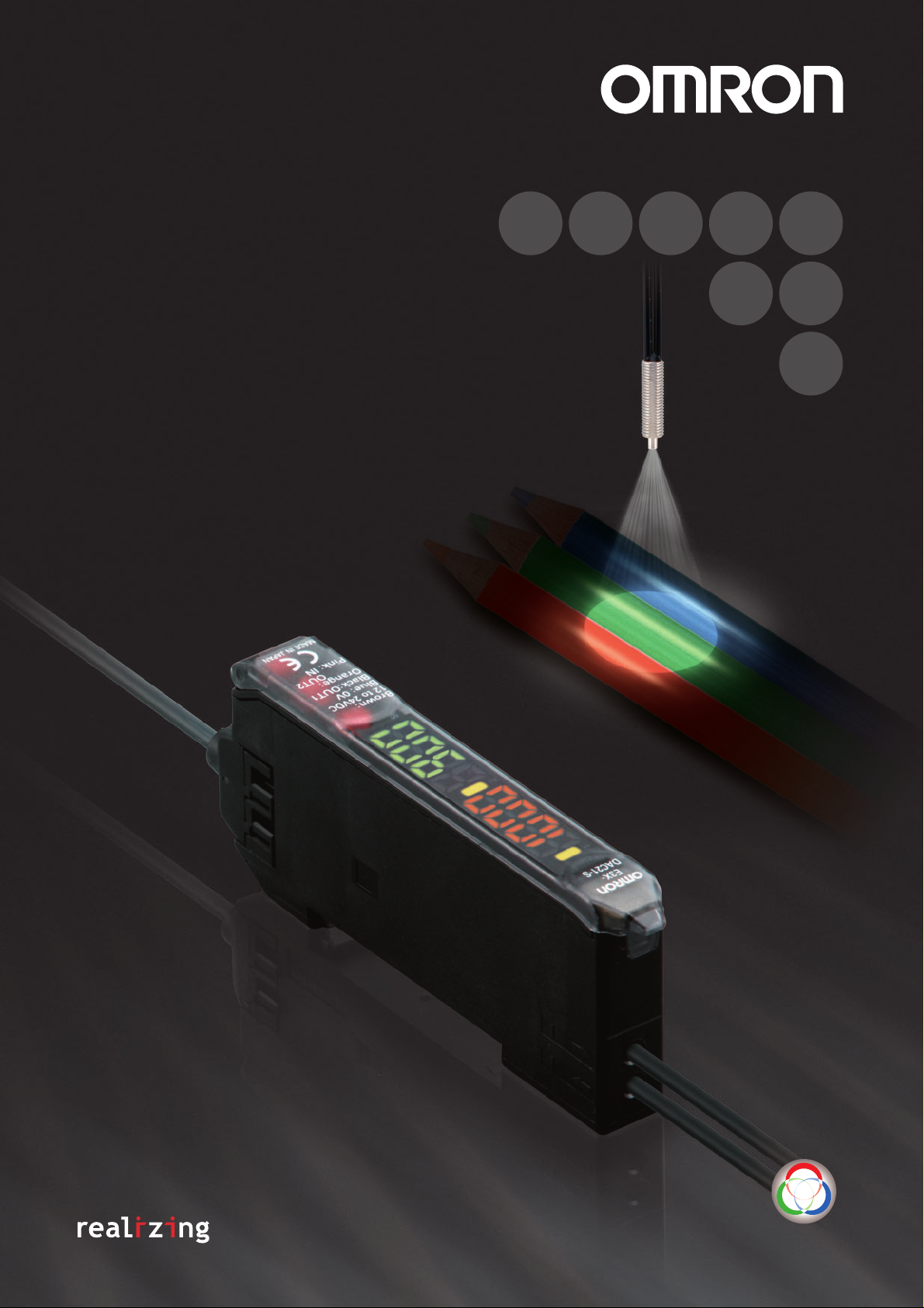
Color Sensing
Digital Fiber Sensor
E3X-DAC-S
Easy and Reliable
The Fiber Sensor That Sees in Color
New Model with Four-color Determination for Even
More Complete Color-sensing Fiber Sensors
Color Sensing
Page 2
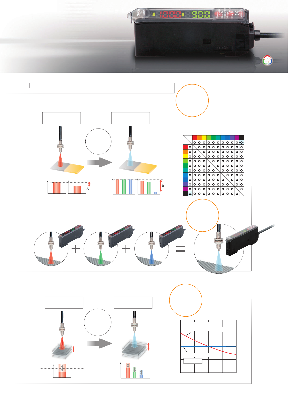
Color-Sensing
Engine
Easy and Reliable ... Featuring a Color-sensing Engine
The color-sensing engine uses three parameters, RGB, to process
incident light. It detects color information from the workpiece for precise
detection of color differences.
Incident light
intensity
Intensity Detection
(Conventional Type)
100
90
Unstable...
RGB ratio
10
Color Detection
(Color Sensing Type)
100
100
100
90
Color Sensing
Precise
Detection
Color VS. Detection Capability
Blue
Blue-purple
Purple
Red-purple
White
Red
Yellow-red
Yellow
Yellow-green
Green
Blue-green
White
Red
Yellow-red
Yellow
Yellow-green
Green
Blue-green
Blue
Blue-purple
Purple
80
90
10
Red-purple
Black
Black
A high-power white LED and a multi-RGB processing system combine to cover all
RGB wavelengths, enabling easy and accurate detection of workpieces without
having to use a different light source to match each one.
Changes in the three parameters are processed as a ratio, so they are
not affected by light-intensity variations due to workpiece movement.
Resists
Incident light
intensity
Intensity Detection
(Conventional Type)
80 to 130
Misdetec-
tion...
RGB ratio
Color Detection
(Color Sensing Type)
8 : 5 : 3
Movement
100%
50%
0%
−50%
Digital value (%)
−100%
−20% −10% 10% 20%
No Need
to Select
Intensity
Detection
Color Detection
Not affected
0%
Distance change (%)
Affected
Page 3
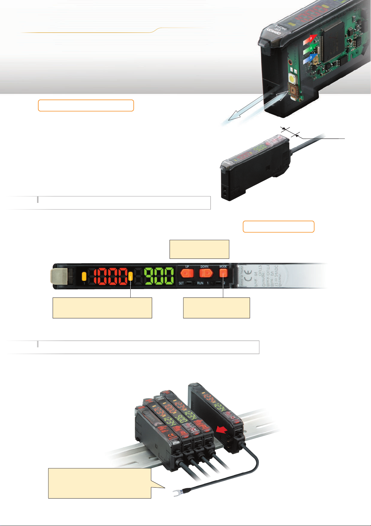
A m p lif ier U n it
Thinnest in the Industry
A Slim, 10-mm-wide Amplifier Unit
Use of a white LED and a one-package RGB light-receiving
element has made it possible to unify the Amplifier Unit,
both in size and operation, with conventional models.
If detection should become unstable, the Amplifier Unit can
be separately replaced to immediately regain stability.
Easy and Reliable ... Ease of Use and Smart Functions
10 mm
In addition to ensuring easy use, we have added a number of smart
functions, such as remote control to simplify setup, and twin
sensing and output to simultaneously distinguish two registered
colors. (advanced models)
Easy to Understand
A double display for easy, precise setting.
Reliable
Setting guide function.
One push is all it takes.
Easy Setting
First in Its Class
This function guides the user to
ensure that the workpiece is in an
appropriate position for teaching.
(Indicates OVER, OK, or LOW.)
Easy and Reliable ... Simplified Wiring Connector Reduces Work Steps
OMRON's unique simplified wiring connectors provide
the power for each added Sensor. Up to 16 Units can
be mounted, including a combination of Digital Fiber
Sensors and other simplified wiring connector
products such as Digital Laser Sensors.
Power is supplied through the connector,
so only one output wire is
required. (For adding Sensors)
From left to right
Digital Fiber Sensors: E3X-NA
E3X-DA-S/MDA
E3X-DAC-S
Digital Laser Sensor: E3C-LDA
Proximity Sensor: E2C-EDA
Page 4
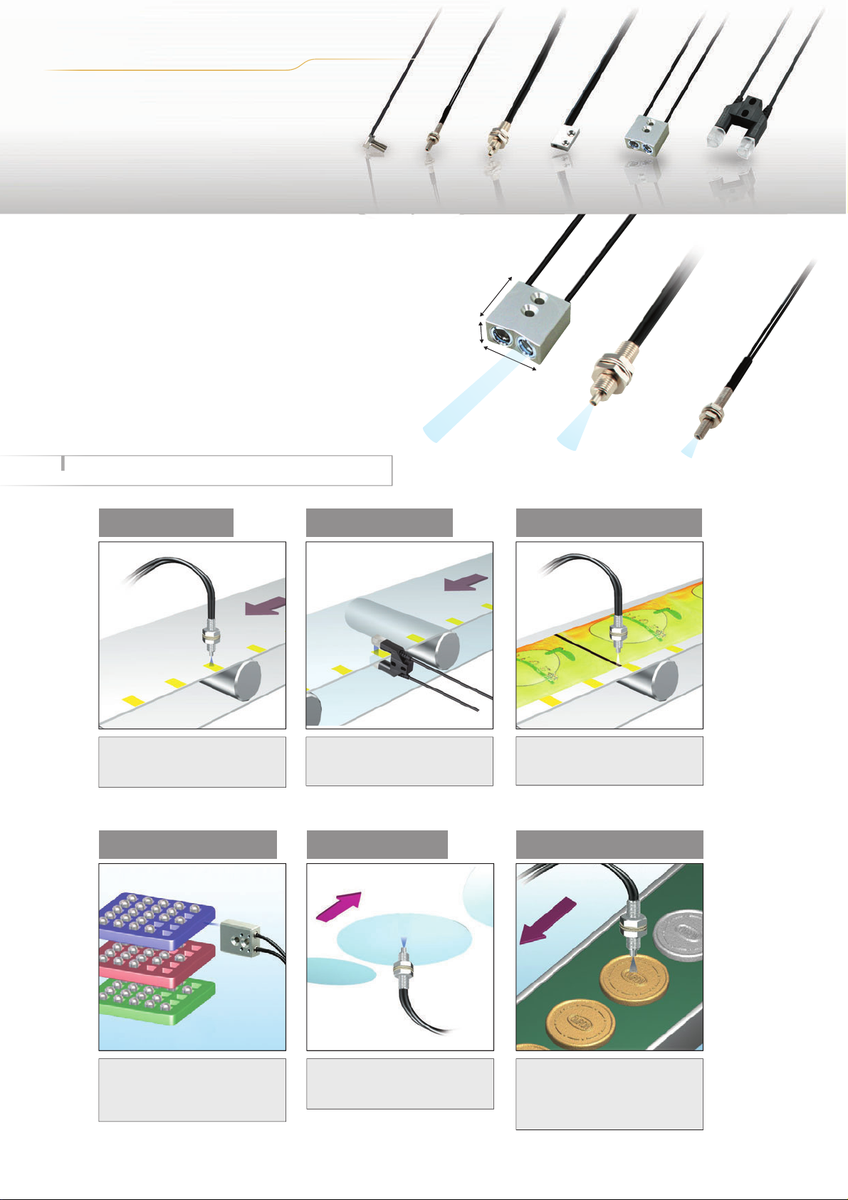
Application
Wide Range of
Fiber Heads Available
Select from a wide range of Fiber Heads to match
the workpiece and working space. This makes
installation possible even in small spaces.
Long-distance
Fiber Head
E32-A09
23 mm
9 mm
20 mm
Many Compact Heads
General-purpose
Fiber Head
E32-CC200
M6 screw
Compact
Fiber Head
E32-C31
M3 screw
Easy and Reliable Applications (Examples)
Detecting Marks
Because it distinguishes RGB
ratios, detection is highly resistant
to workpiece movement.
Distinguishing Trays * Detecting Wafers
Distinguishing
Semi-transparent Objects
Through-beam Fiber Heads are
capable of detecting color differences
in semi-transparent objects.
Detection distance:
30 mm
Detection distance:
9 mm
Detection distance:
3 mm
Detecting Black Marks
In Black Mode, black seam tape and
other black marks can be detected
regardless of film color or patterns.
Detecting Products on
Conveyors
Four-color determination greatly
reduces the work required for line
switchovers.
* Switching banks requires 300 ms.
Workpieces that absorb a specific
wavelength can be detected with
a wide range of wavelengths.
If you teach the conveyor (i.e., the
background), you can detect
workpieces even if they have
different colors, shapes, or gloss.
Page 5
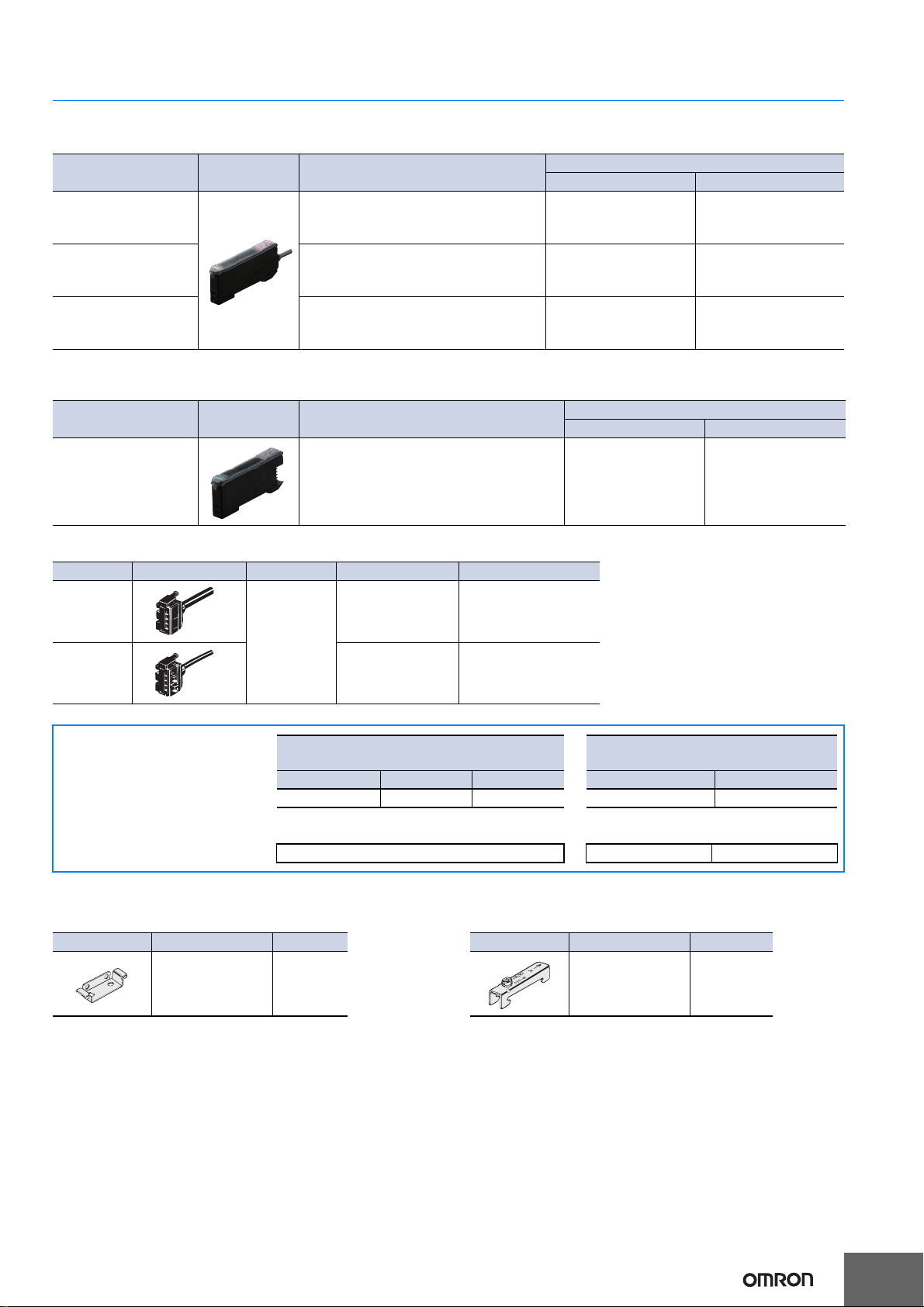
E3X-DAC-S
Combining Amplifier Units and
Connectors
Amplifier Units and Connectors are sold separately. Refer to the following tables when
placing an order.
When Using 5 Amplifier Units
Amplifier Unit
Applicable Connector
(Order Separately)
Model NPN output PNP output Master Connector Slave Connector
Standard models E3X-DAC6-S E3X-DAC8-S
+
E3X-CN11 E3X-CN12
Amplifier Units (5 Units) + 1 Master Connector 4 Slave Connectors
Ordering Information
Amplifier Units
Pre-wired model (Standard cable length 2 m)
Item Appearance Functions
Standard models Timer, Response speed change E3X-DAC11-S 2M E3X-DAC41-S 2M
NPN output PNP output
Model
Advanced models
(2-color simultaneous
determination)
Advanced models
(4-color determination*)
* Four-color determination is enabled by switching between banks for two outputs using an external input.
Standard models + Simultaneous deter-
mination (2 colors), AND/OR output, Re-
mote setting
Standard models + Determination (4 col-
ors), AND/OR output, bank switching
E3X-DAC21-S 2M E3X-DAC51-S 2M
E3X-DAC21B-S 2M E3X-DAC51B-S 2M
Amplifier Units with Connectors (Amplifier Unit Connectors must be purchased separately.)
Item Appearance Functions
Standard models Timer, Response speed change E3X-DAC6-S E3X-DAC8-S
NPN output PNP output
Model
Amplifier Unit Connectors (Order Separately) Note: Protector seals are provided as accessories.
Item Appearance Cable length No. of conductors Model
Master
Connector
2 m
Slave
Connector
3 E3X-CN11
1 E3X-CN12
Accessories (Order Separately)
Mounting Bracket End Plate
Appearance Model Quantity
E39-L143 1
Appearance Model Quantity
PFP-M 1
5
Page 6

E3X-DAC-S
6
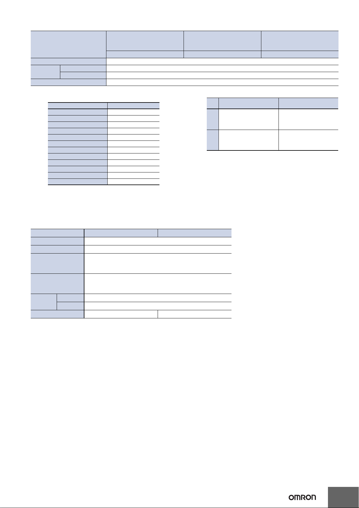
Ratings and Specifications
Amplifier Units
Advanced models
Type Standard models
(2-color simultaneous
determination)
Item Model E3X-DAC@-S@ (@: 11/41/6/8) E3X-DAC@-S@ (@: 21/51) E3X-DAC@B-S@ (@: 21/51)
Sensing distance Depends on the Fiber Unit. Refer to pages 8 to 10.
Sensing object
Light source (wavelength) White LED (420 to 700 nm)
Sensing method
Number of registered colors
Power supply voltage 12 to 24 VDC ±10%, ripple (p-p) 10% max.
Power consumption 960 mW max. (current consumption: 40 mA max. at power supply voltage of 24 VDC)
Control output
Number of control outputs 1 output
External input
(See note 3. (page 7))
Protection circuits Reverse polarity for power supply connection, output short-circuit, Reversed output polarity protection
Mutual interference prevention Up to 10 Units (optical communications control)
Super-high-speed
mode
Response
time
Sensitivity setting
(color registration, allowable
range)
Functions
Display
Digital display Seven-segment displays (Main display: Red, Sub-display: Green)
Digital direction Switchable between normal and reversed.
Ambient illumination (Receiver
side)
Ambient temperature range
(See note 6.)
Ambient humidity range Operating and storage: 35% to 85% (with no condensation)
Insulation resistance 20 MΩ min. (at 500 VDC)
Dielectric strength 1,000 VAC at 50/60 Hz for 1 minute
Vibration resistance Destruction: 10 to 50 Hz with a 1.5-mm double amplitude for 2 hrs each in X, Y and Z directions
Shock resistance Destruction: 500 m/s2, for 3 times each in X, Y and Z directions
Degree of protection IEC 60529 IP50 (with Protective Cover attached)
Connection method
Note: Refer to page 7 for notes 1 to 6.
(See note 4.)
High-speed mode
Standard mode
High-resolution
mode
Operating mode
Timer function Timer type: OFF delay, ON delay, or one-short, Timer time: 1 ms to 5 s (variable)
Control outputs --- Output for each channel, AND output, and OR output
Remote control ---
Display switch
(See note 5.)
Initialization Initial reset (factory defaults) or user reset (saved settings)
Zero-reset Provided Initial reset (factory default)
Reflective models: Standard 11 color cards (See note 1.), Through-beam models: Opaque or translucent object
C Mode: RGB ratio determination (or I Mode: Light intensity determination for red, green, or blue, Black Mode:
Determination of total light intensity for red, green, and blue) (See note 2.)
1 2 (simultaneous determination)
NPN or PNP open collector
Load power supply voltage: 26.4 VDC max.
Load current: 50 mA max. (residual voltage: 2 V max.)
2 outputs
---
Operate or reset: 60 μs Operate or reset: 120 μs
Operate or reset: 300 μs Operate or reset: 600 μs
Operate or reset: 1 ms Operate or reset: 2 ms
Operate or reset: 4 ms Operate or reset: 8 ms
Teaching (one-point teaching or teaching with/without workpiece) or manual adjustment
ON for match (ON for same color as registered color) or ON for mismatch (ON for different color from registered color)
Seven patterns total: Match + Threshold, Margin + Threshold, Analog bar display, Peak + Bottom, etc.
Operation indicator (orange)/
I mode display indicator (orange)
Incandescent lamp: 3,000 lux
Sunlight: 10,000 lux
Operating: −25°C to 55°C
Storage: −30°C to 70°C (with no icing or condensation)
Pre-wired (Standard cable length 2
m) or Amplifier Unit connector
(Units connected: 16 max.)
Remote control
One-point teaching, teaching with/
without workpiece, zero reset, and
light emission OFF
Channel 1 and channel 2 operation indicators (orange)
Pre-wired (Standard cable length 2 m)
Advanced models
(4-color determination)
4 (2-color determination × 2
banks)
Bank switching
Bank switching (Switching between
banks A, B, C, and D.)
Page 7
E3X-DAC-S
Type Standard models
Advanced models
(2-color simultaneous
determination)
Advanced models
(4-color determination)
Item Model E3X-DAC@-S@ (@: 11/41/6/8) E3X-DAC@-S@ (@: 21/51) E3X-DAC@B-S@ (@: 21/51)
Weight (packed state) Pre-wired model: Approx. 100 g, Amplifier unit connector model: Approx. 55 g
Materials
Case Polybutylene terephthalate (PBT)
Cover Polycarbonate (PC)
Accessories Instruction manual
Note:1.Sensing Object: Standard Color Card (230 Colors) from Japan Color
Enterprise Co., Ltd.)
Color (11 standard colors) Munsell color notation
White N9.5
Red 4R 4.5/12.0
Yellow/red 4YR 6.0/11.5
Yellow 5Y 8.5/11.0
Yellow/green 3GY 6.5/10.0
Green 3G 6.5/9.0
Blue/green 5BG 4.5/10.0
Blue 3PB 5.0/10.0
Blue/purple 9PB 5.0/10.0
Purple 7P 5.0/10.0
Red/purple 6RP 4.5/12.5
Black (N2.0)
2.When teaching with/without a workpiece, the best sensing method will
be automatically selected (RGB ratio (C Mode) or light intensity determination (I Mode)). If color differences are not strong enough and RGB
ratios would result in unstable detection, then light intensity determination (I Mode) will be selected.
The detection mode can also be set to C, I, or Black Mode.
3.Input Specifications
Contact input
(relay or switch)
ON: Shorted to 0 V (sourcing
NPN
PNP
Refer to the Instruction Manual for the external input pulse width.
A pulse width of 300 ms or longer is required to switch banks for the
E3X-DAC@B-S.
4. Mutual interference prevention cannot be used in super-high-speed
mode, and light intensity determination (I Mode) must be used.
5. With light intensity determination (I Mode), the correlation is not displayed, but rather the light intensity is displayed.
6.The allowable ambient operating temperature changes according to the
number of Units that are linked.
2 Units: −25 to 55°C, 3 to 10 Units: −25 to 50°C, and 11 to 16 Units:
−25 to 45°C
current: 1 mA max.).
OFF: Open or shorted to Vcc.
ON: Shorted to Vcc (sinking
current: 3 mA max.).
OFF: Open or shorted to 0 V.
Non-contact input
(transistor)
ON: 1.5 V max. (sourcing cur-
rent: 1 mA max.)
Vcc - 1.5 V to Vcc (leakage
OFF:
current: 0.1 mA max.)
ON: Vcc - 1.5 V to Vcc (sink-
ing current: 3 mA max.)
OFF: 1.5 V max. (leakage cur-
rent: 0.1 mA max.)
Amplifier Unit Connectors
Item Model E3X-CN11 E3X-CN12
Rated current 2.5 A
Rated voltage 50 V
20 mΩ max. (20 mVDC max., 100 mA max.)
Contact resistance
No. of insertions
Materials
Housing Polybutylene terephthalate (PBT)
Contacts Phosphor bronze/gold-plated nickel
Weight (packed state) Approx. 55 g Approx. 25 g
(The figure is for connection to the Amplifier Unit and the adjacent
Connector. It does not include the conductor resistance of the cable.)
Destruction: 50 times
(The figure for the number of insertions is for connection to the Amplifier Unit and the adjacent Connector.)
7
Page 8
E3X-DAC-S
8
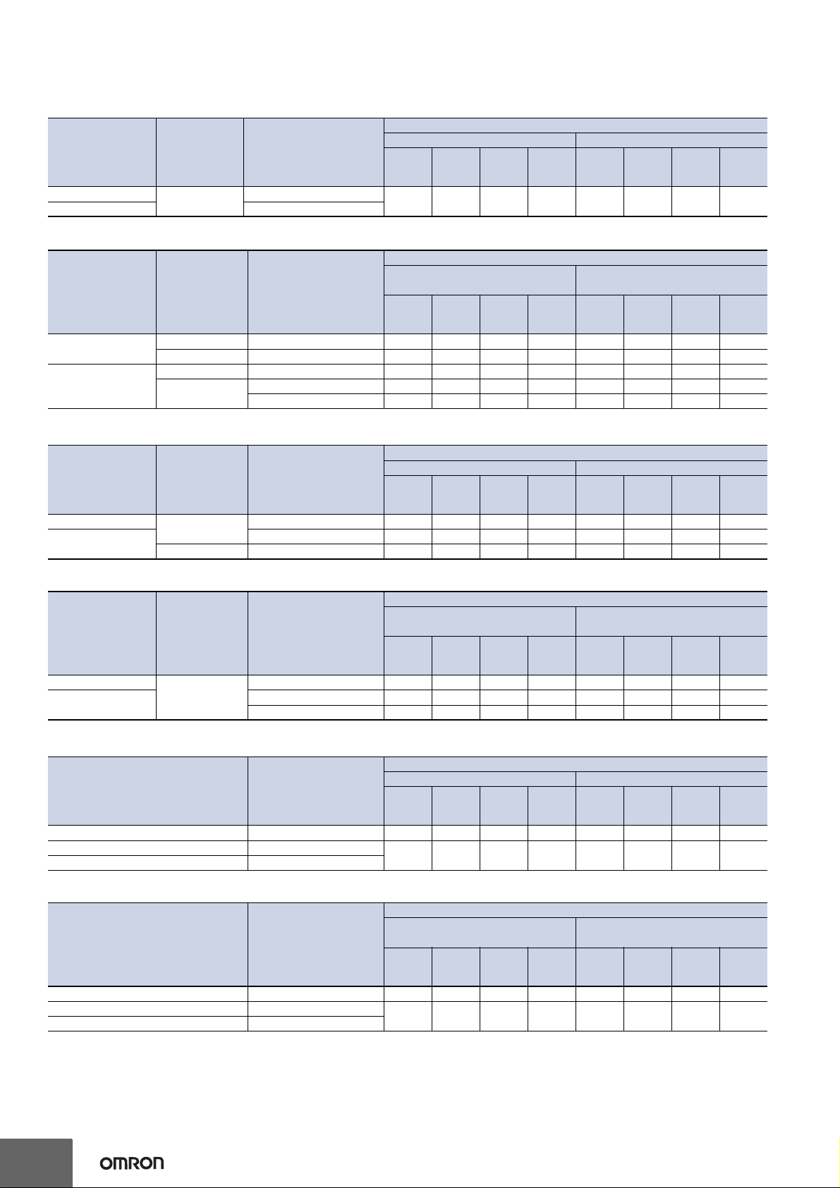
Sensing Distance
Threaded Models
Through-beam Fiber Units
Sensing direction Size Model
resolution
Right-angle
Straight E32-T11R 2M
* These sensing distances are recommended to make the most of the detection capabilities of the Sensor.
M4
E32-T11N 2M
Reflective Fiber Units
Sensing direction Size Model
resolution
Right-angle
Straight
M3 E32-C31N 2M 7.7 6 4.8 2.1 1.6 1.2 0.9 0.7
M6 E32-C11N 2M 35 26 22 9 7.5 5 4.5 3
M3 E32-C31 2M 17 13 11 4.5 3.7 2.7 2.2 1.5
M6
E32-D11R 2M 42 32 26 11 8.5 6 5 3.5
E32-CC200 2M 60 45 35 16 12974
Cylindrical Models
Through-beam Fiber Units
Size
1.5 dia.
3 dia.
* These sensing distances are recommended to make the most of the detection capabilities of the Sensor.
Sensing
direction
Top-view
Side-view E32-T14LR 2M 55 44 38 19 12 8.5 7 6.5
E32-T22B 2M 70 55 48 40 15 11 9 6
E32-T12R 2M 150 110 95 50 30 22 18 16
Model
resolution
Reflective Fiber Units
Size
1.5 dia.
3 dia.
Sensing
direction
Top-view
Model
resolution
E32-D22B 2M 8.8 6.7 5.8 2.1 1.8 1.3 1.1 0.7
E32-D221B 2M 19 15 13 4.5 4.1 3 2.4 1.5
E32-D32L 2M 35 26 22 9 7.5 5 4.5 3
Flat Models
Through-beam Fiber Units
Sensing direction Model
resolution
Top-view E32-T15XR 2M 150 110 95 50 30 22 18 16
Side-view E32-T15YR 2M
Flat-view E32-T15ZR 2M
* These sensing distances are recommended to make the most of the detection capabilities of the Sensor.
Reflective Fiber Units
Sensing direction Model
resolution
Top-view E32-D15XR 2M 42 32 26 11 8.5 6 5 3.5
Side-view E32-D15YR 2M
Flat-view E32-D15ZR 2M
Opaque object (Translucent object) *
High-
Standard
mode
150 110 95 50 30 22 18 16
High-
Standard
mode
Opaque object (Translucent object) *
High-
Standard
mode
High-
Standard
mode
Opaque object (Translucent object) *
High-
Standard
mode
55 44 38 19 12 8.5 7 6.5
High-
Standard
mode
10 7.5 6.5 2.5 2.1 1.5 1.3 0.9
High-speed
mode
White paper
mode
mode
White paper
mode
mode
White paper
mode
mode
High-speed
mode
High-speed
mode
High-speed
mode
High-speed
mode
High-speed
mode
Sensing distance (mm)
Super-highspeedmode
Sensing distance (mm)
Super-highspeedmode
Sensing distance (mm)
Super-highspeedmode
Sensing distance (mm)
Super-highspeedmode
Sensing distance (mm)
Super-highspeedmode
Sensing distance (mm)
Super-highspeedmode
High-
resolution
mode
Standard color card (11 colors)
(mutual determination)
High-
resolution
mode
High-
resolution
mode
Standard color card (11 colors)
(mutual determination)
High-
resolution
mode
High-
resolution
mode
Standard color card (11 colors)
(mutual determination)
High-
resolution
mode
Standard
mode
Standard
mode
Standard
mode
Standard
mode
Standard
mode
Standard
mode
High-speed
mode
High-speed
mode
High-speed
mode
High-speed
mode
High-speed
mode
High-speed
mode
Super-highspeedmode
Super-highspeedmode
Super-highspeedmode
Super-highspeedmode
Super-highspeedmode
Super-highspeedmode
Page 9

E3X-DAC-S
Sleeve Models
Through-beam Fiber Units
Sensing distance (mm)
Sensing direction Model
resolution
Top-view E32-TC200BR 2M 150 110 95 50 30 22 18 16
* These sensing distances are recommended to make the most of the detection capabilities of the Sensor.
Reflective Fiber Units
Sensing direction Model
resolution
Top-view E32-DC200BR 2M 42 32 26 11 8.5 6 5 3.5
Small-spot, Reflective Sensors
Spot diameter
6 dia. 50 E32-L15 2M
* The distance to differentiate between blue and blue-purple is 43 to 53 mm.
Center distance
(mm)
Model
resolution
40 to 80 40 to 80 40 to 80 40 to 80
High-power Beam
Through-beam Fiber Units
Sensing direction Aperture angle Model
resolution
Top-view 10 ° E32-T17L 10M 4,300 3,200 2,800 1,400 900 600 500 460
Side-view 30 ° E32-T14 2M 950 700 600 300 200 140 120 100
Right-angle 12 ° E32-T11N 2M + E39-F1 1,000 750 650 340 220 150 130 110
Top-view 12 ° E32-T11R 2M + E39-F1 1,000 750 650 340 220 150 130 110
Side-view 60 ° E32-T11R 2M + E39-F2 110 85 70 36 22 16 14 12
Top-view 12 ° E32-T11 2M + E39-F1 1,000 750 650 320 200 150 120 110
Side-view 60 ° E32-T11 2M + E39-F2 18 0 14 0 1 20 60 38 28 22 20
Top-view 12 ° E32-T61-S 2M + E39-F1 950 700 600 320 200 140 120 100
Side-view 60 ° E32-T61-S 2M + E39-F2 120 95 80 42 26 19 16 14
* These sensing distances are recommended to make the most of the detection capabilities of the Sensor.
Narrow View
Through-beam Fiber Units
Sensing direction Aperture angle Model
resolution
Side-view 4 °
* These sensing distances are recommended to make the most of the detection capabilities of the Sensor.
E32-T24S 2M 360 280 240 120 75 55 46 40
E32-T22S 2M 500 400 350 170 110 80 65 55
Opaque object (Translucent object) *
High-
Standard
mode
High-
Standard
mode
High-
Standard
mode
Opaque object (Translucent object) *
High-
Standard
mode
Opaque object (Translucent object) *
High-
Standard
mode
High-speed
mode
White paper
mode
White paper
mode
mode
mode
mode
High-speed
mode
High-speed
mode
High-speed
mode
High-speed
mode
Super-highspeedmode
Sensing distance (mm)
Super-highspeedmode
Sensing distance (mm)
Super-highspeedmode
Sensing distance (mm)
Super-highspeedmode
Sensing distance (mm)
Super-highspeedmode
High-
resolution
Standard color card (11 colors)
resolution
Standard color card (11 colors)
resolution
40 to 55 * 40 to 55 *
resolution
resolution
Standard
mode
Highmode
Highmode
Highmode
Highmode
mode
(mutual determination)
Standard
mode
(mutual determination)
Standard
mode
Standard
mode
Standard
mode
High-speed
mode
High-speed
mode
High-speed
mode
−−
High-speed
mode
High-speed
mode
Super-highspeedmode
Super-highspeedmode
Super-highspeedmode
Super-highspeedmode
Super-highspeedmode
9
Page 10

E3X-DAC-S
10
Chemical-resistant, Oil-resistant
Through-beam Fiber Units
Type
Chemical/oil-re-
sistant
Chemical/oil-resistant at 150°C
* These sensing distances are recommended to make the most of the detection capabilities of the Sensor.
Sensing
direction
Top-view
Side-view
Top-view
Model
resolution
E32-T12F 2M 850 650 550 280 180 120 100 95
E32-T11F 2M 550 420 360 180 110 80 70 60
E32-T14F 2M 100 80 70 35 22 16 13 12
E32-T51F 2M 380 300 250 130 80 55 48 44
Reflective Fiber Units
Type
Chemical/oil-resistant
Chemical-resistant cable
Sensing
direction
Top-view
Model
resolution
E32-D12F 2M 22 17 15 6 4.9 3.5 2.9 2
E32-D11U 2M 42 32 26 11 8.5 6 5 3.5
Bending-resistant
Through-beam Fiber Units
Size Model
resolution
1.5 dia. E32-T22B 2M
M3 E32-T21 2M
M4 E32-T11 2M 190 140 120 60 40 28 24 20
Square E32-T25XB 2M 55 42 36 30 11 8 7 4.5
* These sensing distances are recommended to make the most of the detection capabilities of the Sensor.
Reflective Fiber Units
Size Model
resolution
1.5 dia. E32-D22B 2M
M3 E32-D21 2M
3 dia. E32-D221B 2M
M4 E32-D21B 2M
M6 E32-D11 2M 42 32 26 11 8.5 6 5 3.5
Square E32-D25XB 2M 14109332.11.71.1
Heat-resistant
Through-beam Fiber Units
Heat-resistant temperature Model
resolution
150°C E32-T51 2M 200 160 140 70 44 32 26 22
200°C E32-T81R-S 2M 75 60 50 26 16 11 9.5 8.5
350°C E32-T61-S 2M 120 95 80 42 26 19 16 14
* These sensing distances are recommended to make the most of the detection capabilities of the Sensor.
Reflective Fiber Units
Heat-resistant temperature Model
resolution
150°C E32-D51 2M 55 42 36 14 11 8.5 7 4.5
200°C E32-D81R-S 2M
350°C E32-D61-S 2M
400°C E32-D73-S 2M 13 10 8.5 3.5 2.8 2 1.7 1.2
Opaque object (Translucent object) *
High-
Standard
mode
High-
Standard
mode
Opaque object (Translucent object) *
High-
Standard
mode
70 55 48 40 15 11 9 6
High-
Standard
mode
8.8 6.7 5.8 2.1 1.8 1.3 1.1 0.7
19 15 13 4.5 4.1 3 2.4 1.5
Opaque object (Translucent object) *
High-
Standard
mode
High-
Standard
mode
2015135432.51.5
High-speed
mode
White paper
mode
mode
White paper
mode
mode
White paper
mode
mode
High-speed
mode
High-speed
mode
High-speed
mode
High-speed
mode
High-speed
mode
Sensing distance (mm)
Super-highspeedmode
Sensing distance (mm)
Super-highspeedmode
Sensing distance (mm)
Super-highspeedmode
Sensing distance (mm)
Super-highspeedmode
Sensing distance (mm)
Super-highspeedmode
Sensing distance (mm)
Super-highspeedmode
High-
resolution
mode
Standard color card (11 colors)
(mutual determination)
High-
resolution
mode
High-
resolution
mode
Standard color card (11 colors)
(mutual determination)
High-
resolution
mode
High-
resolution
mode
Standard color card (11 colors)
(mutual determination)
High-
resolution
mode
Standard
mode
Standard
mode
Standard
mode
Standard
mode
Standard
mode
Standard
mode
High-speed
mode
High-speed
mode
High-speed
mode
High-speed
mode
High-speed
mode
High-speed
mode
Super-highspeedmode
Super-highspeedmode
Super-highspeedmode
Super-highspeedmode
Super-highspeedmode
Super-highspeedmode
Page 11

E3X-DAC-S
Area Beam
Through-beam Fiber Units
Sensing distance (mm)
Type Sensing width Model
resolution
Area
* These sensing distances are recommended to make the most of the detection capabilities of the Sensor.
11 mm
30 mm E32-T16WR 2M 360 280 240 120 75 55 46 40
E32-T16PR 2M 240 180 150 80 50 36 30 26
E32-T16JR 2M 200 160 130 65 44 30 26 22
Reflective Fiber Units
Type Sensing width Model
resolution
Array 11 mm E32-D36P1 2M 35 26 22 9 7.5 5 4.5 3
Vacuum-resistant
Through-beam Fiber Units
Heat-resistant temperature Model
resolution
120°C
200°C E32-T84SV 1M 130 100 85 45 28 20 17 15
* These sensing distances are recommended to make the most of the detection capabilities of the Sensor.
E32-T51V 1M 55 42 36 18 11 8.5 7 6
E32-T51V 1M + E39-F1V 280 200 180 90 55 42 35 30
Opaque object (Translucent object) *
High-
Standard
mode
High-
Standard
mode
Opaque object (Translucent object) *
High-
Standard
mode
High-speed
mode
White paper
mode
mode
mode
High-speed
mode
High-speed
mode
Super-highspeedmode
Sensing distance (mm)
Super-highspeedmode
Sensing distance (mm)
Super-highspeedmode
High-
resolution
Standard color card (11 colors)
resolution
resolution
Standard
mode
Highmode
Highmode
mode
(mutual determination)
Standard
mode
Standard
mode
High-speed
mode
High-speed
mode
High-speed
mode
Super-highspeedmode
Super-highspeedmode
Super-highspeedmode
11
Page 12

E3X-DAC-S
Engineering Data (Reference Value)
Color vs. Detection Capability
E3X-DAC@-S+E32-CC200
White Red
White
Red
❍ ❍❍❍❍❍❍❍❍❍❍
Yellow/
❍❍ ❍❍❍❍❍❍❍❍❍
red
Yellow
❍❍❍ ❍❍❍❍❍❍❍❍
Yellow/
❍❍❍❍ ❍❍❍❍❍❍❍
green
Green
❍❍❍❍❍ ❍❍❍❍❍❍
Blue/
❍❍❍❍❍❍ ❍❍❍❍❍
green
Blue
❍❍❍❍❍❍❍ ❍❍❍❍
Blue/
❍❍❍❍❍❍❍❍ ❍❍❍
purple
Purple
❍❍❍❍❍❍❍❍❍ ❍❍
Red/
❍❍❍❍❍❍❍❍❍❍ ❍
purple
∗
Black
(❍) ❍❍❍❍❍❍❍❍❍❍
Yellow/
red
❍❍❍❍❍❍❍❍❍❍(❍)
Yellow
Yellow/
green
Green
Blue/
green
Blue
Blue/
purple
Purple
Red/
purple
Black
∗
No Need
to Select
Model with Red Light Source
(E3X-DA@-S)
White Red
Yellow
Green
Blue
Purple
White
Red
Yellow
Green
545 2
Blue
645 2
Purple
32322 4
Black
978 4
Black
5639
4427
5538
Model with Green
Light Source
(E3X-DAG@-S)
White Red
Yellow
Green
Blue
Purple
8 3510
White
8 553
Red
536
Yellow
Green
536
Blue
33 4
Purple
533 3
Black
10 6 6 4 3
Black White Red
Model with Blue
Light Source
(E3X-DAB@-S)
White
Red
Yellow
Green
Blue
Purple
Black
Sensing distance: 9 mm (i.e., the teaching distance)
❍: Detection possible, ×: Detection not possible.
* Use 2-point teaching to distinguish between white and black.
Color Detection Characteristics Color Detection Capability vs. Distance
E3X-DAC@-S+E32-CC200 E3X-DA@-S+E32-CC200
E3X-DAB/G@-S+E32-CC200 (Model with single-color light
1000
900
800
700
600
500
Correlation (Digital Display)
400
300
200
100
0
Red
White
Yellow
Yellow/red
Green
Yellow/green
Blue
Blue/green
Purple
Blue/purple
Sensing object color
Sensing distance: 9 mm
(i.e., the teaching
distance)
Registered Color
Red
Yellow
Green
Blue
Purple
Red/purple
source)
140
120
100
80
60
40
20
0
Number of colors differentiated (combinations)
0
E3X-DAC-S
Model with blue
light source
E3X-DAB-S
Model with green
light source
E3X-DAG-S
X
For 2-point teaching
For one-point
teaching
3530252015105
Sensing distance X (mm)
= Teaching distance
Correlation vs. Distance Correlation vs. Angle
E3X-DAC@-S+E32-CC200 E3X-DAC@-S+E32-CC200
Yellow
Green
Blue
Purple
553 38
532
5242
3223
342 6
322 4
8 364
Black
12
5
0
−5
−10
Change in correlation (%)
−15
−20
−25
−40−30−20−
Sensing
object
10 10 20 30 400
Change in distance X (%)
Sensing distance: 9 mm
(i.e., the teaching
distance)
X
Registered Color
Red
Green
Blue
5
0
−5
−10
Change in correlation (%)
−15
−20
−25
−
20−15−10−5 5 10 15 200
Sensing object
Sensing distance: 9 mm
(= Teaching distance)
Registered Color
+θ
−θ
Red
Green
Blue
Angle of incline θ (°)
Page 13

Output Circuit Diagrams
Match
Mismatch
ON
OFF
ON
OFF
Operate
Reset
(Between brown and black leads)
Operation
indicator
(orange)
Output
transistor
Load
(relay)
Load
I mode indicator (orange)
Brown
Black
Blue
Control output
12 to
24 VDC
Display
Photoelectric
Sensor
main
circuit
Operation
indicator
(Orange)
Match
Mismatch
ON
OFF
ON
OFF
Operate
Reset
(Between brown and black leads)
Operation
indicator
(orange)
Output
transistor
Load
(relay)
Match
Mismatch
ON
OFF
ON
OFF
Operate
Reset
(Between brown and black leads)
Operation
indicator
(orange)
Output
transistor
Load
(rela
y)
Orange
Pink
Load
External input
(Bank switching
input) *
Brown
Black
Blue
12 to
24 VDC
Display
Photoelectric
Sensor
main
circuit
Ch1
operation
indicator
(orange)
Ch2 operation indicator
(orange)
Load
Ch2 control output
Ch1
control output
* For the E3X-DAC@B-S
Match
Mismatch
ON
OFF
ON
OFF
Operate
Reset
(Between brown and black leads)
Operation
indicator
(orange)
Output
transistor
Load
(relay)
Control output
Brown
Black
Blue
12 to
24 VDC
Display
Photoelectric
Sensor
main
circuit
Operation
indicator
(Orange)
Load
I mode indicator (orange)
Brown
Black
Blue
12 to
24 VDC
Display
Photoelectric
Sensor
main
circuit
Load
Load
Orange
Pink
Ch1
operation
indicator
(orange)
Ch2 operation indicator (orange)
Ch2 control output
Ch1 control output
External input
(Bank switching
input) *
* For the E3X-DAC@B-S
Match
Mismatch
ON
OFF
ON
OFF
Operate
Reset
(Between blue and black leads)
Operation
indicator
(orange)
Output
transistor
Load
(rela
y)
Match
Mismatch
ON
OFF
ON
OFF
L-ON
D-ON
T
T
Match
Mismatch
ON
OFF
ON
OFF
L-ON
D-ON
T
T
CH1
CH2
ON
OFF
ON
OFF
ON
OFF
ON
OFF
OUT
(OR)
OUT
(AND)
CH1
CH2
ON
OFF
ON
OFF
ON
OFF
ON
OFF
ON
OFF
One-shot
(AND)
OFF delay
(AND)
ON delay
(AND)
T
T
T
NPN Output
Model
Operation
mode
Timing charts
Operation
selector
E3X-DAC-S
Output circuit
E3X-DAC11-S
E3X-DAC6-S
E3X-DAC21-S
E3X-DAC21B-S
PNP Output
Model
E3X-DAC41-S
E3X-DAC8-S
E3X-DAC51-S
E3X-DAC51B-S
ON for
match
ON for mis-
match
ON for
match
ON for mis-
match
Operation
mode
ON for
match
ON for mis-
match
ON for
match
Timing charts
Match
Mismatch
Operation
ON
indicator
OFF
(orange)
ON
Output
transistor
OFF
Operate
Load
y)
(rela
Reset
(Between blue and black leads)
Match
Mismatch
Operation
ON
indicator
OFF
(orange)
ON
Output
transistor
OFF
Operate
Load
y)
(rela
Reset
(Between blue and black leads)
Match
Mismatch
Operation
ON
indicator
OFF
(orange)
ON
Output
transistor
OFF
Operate
Load
(relay)
Reset
(Between blue and black leads)
LIGHT ON
(L-ON)
DARK ON
(D-ON)
LIGHT ON
(L-ON)
DARK ON
(D-ON)
Operation
selector
LIGHT ON
(L-ON)
DARK ON
(D-ON)
LIGHT ON
(L-ON)
Output circuit
Note:1. Timing Charts for Timer Function Settings (T: Set Time) 2.Control Output (AND, OR, Sync) and Timing Chart for Timer Settings
ON for mis-
match
ON delay OFF delay One-shot
Match
Mismatch
ON
L-ON
OFF
ON
D-ON
OFF
T
T
DARK ON
(D-ON)
(T: Set Time)
13
Page 14

E3X-DAC-S
Nomenclature
Amplifier Units
Standard Models
E3X-DAC@-S (@: 11/41/6/8)
Main Display (Red)
Incident level, function, etc.
Lock lever
Locks the fiber.
Sub-Display (Green)
Threshold, function settings, etc.
Operation Keys
Function setting operations
UP
DOWN
MODE
Advanced Models (2-color simultaneous determinatio n,
4-color determination)
E3X-DAC@-S (@: 21/51), E3X-DAC@B-S (@: 21/51)
Main Display (Red)
Incident level, function, etc.
Lock lever
Locks the fiber.
Sub-Display (Green)
Threshold, function settings, etc.
Operation Keys
Function setting operations
UP
DOWN
MODE
Operation Selector
Operation Indicator (orange)
ON when output is ON.
OFF when output is OFF.
I Mode Indicator
Lit orange: Operation
in I Mode.
Mode Selector
Use to select SET
or RUN mode.
Use to switch between Light ON
and Dark ON modes.
Safety Precautions
WARNING
This product is not designed or rated for ensuring safety of persons either directly or indirectly.
Do not use it for such purposes.
CAUTION
Do not use the product with voltage in excess
of the rated voltage. Excess voltage may result
in malfunction or fire.
Never use the product with an AC power supply. Otherwise, explosion may result.
High-temperature environments may result in
burn injury.
Channel Switch
Ch1 Operation Indicator
O
N when output is ON.
OFF when output is OFF.
Ch2 Operation Indicator
ON when output is ON.
OFF when output is OFF.
Used to select the channel to
display and set.
Mode Selector
Use to select SET
or RUN mode.
Precautions for Safe Use
The following precautions must be observed to ensure safe
operation of the Sensor.
1. Do not use the Sensor in an environment where explosive
or flammable gas is present.
2. Do not use the Sensor in a location subject to splatterin g
of water, oils, or chemicals.
3. Do not attempt to disassemble, repair, or modify the Sensor.
4. Do not apply voltages o r currents that exceed the rated
range to the Sensor.
5. Do not use the Sensor in an ambient atmosphere or environment that exceeds the ratings.
6. Wire the power supply correctly, including the pola r ity.
7. Connect the load correctly.
8. Do not short-circuit the load at both ends.
9. Do not use the Sensor if the case is damaged.
10. Dispose of the Sensor as industrial waste.
11. Do not use the Sensor in locations subject to direct sunlight.
12. Burn injury may occur. The Sensor surface temperature
rises depending on application conditions, such as the
ambient temperature and the power supply voltage. Use
caution when operating or performing maintenance on the
Sensor.
14
Page 15

Precautions for Correct Use
Do not use the product in atmospheres or environments that
exceed product ratings.
Amplifier Unit
● Designing
Operation after Turning Power ON
The Sensor is ready to detect within 200 ms after the power
supply is turned ON. If the Sensor and load are connected to
separate power supplies, be sure to turn ON the Sensor first.
Time may be required for the degree of coincidence to stabilize after the power supply is turned ON.
Operation When Turning Power OFF
Output pulses may occur when the power is turned OFF. Turn
OFF the power supply to the load and the load line before
turning OFF the power supply to the Sensor.
● Mounting
Connecting and Disconnecting Connectors
Mounting Connectors
1. Insert the Master or Slave Connector into the Amplifier Unit
until it clicks into place.
Insert
2. Attach the protector seals (provided as accessories) to the
sides of master and slave connectors that are not connected.
E3X-DAC-S
Adding and Removing Amplifier Units
Adding Amplifier Units
1. Mount the Amplifier Units one at a time onto the DIN track.
2. Slide the Amplifier Units together, line up the clips, and
press the Amplifier Units together until they click into place.
Click into place
Removing Amplifier Units
Slide Amplifier Units away from each other, and remove from
the DIN track one at a time. (Do not attempt to remove Amplifier Units from the DIN track without separating them first.)
Note:1. The specifications for ambient temperature will vary according to the
number of Amplifier Units used together. For details, refer to Ratings
and Specifications.
2.Always turn OFF the power supply before joining or separating Amplifier Units.
Mounting the End Plate (PFP-M)
An End Plate should be used if there is a possibility of the Amplifier Unit moving, e.g., due to vibration.
Seal
Note: Attach the seals to the sides with grooves.
Removing Connectors
1. Slide the slave Amplifier Unit(s) for which the Connector is
to be removed away from the rest of the group.
2. After the Amplifier Unit(s) has been separated, press down
on the lever on the Connector and remove it. (Do not attempt to remove Connectors without separating them from
other Amplifier Units first.)
Press down
Lever
Remove
End Plate
Fiber Connection
The E3X Amplifier Unit has a lock button for easy connection
of the Fiber Unit. Connect or disconnect the fibers using the
following procedures:
1. Connection
Open the protective cover, insert the fibers according to the fiber insertion marks on the side of the Amplifier Unit, and lower
the lock lever.
Lock button
Unlocked
Locked
Fiber insertion mark
Fiber
Note: Do not pull on, compress, or otherwise exert excessive force on the fi-
bers after connecting them to the Amplifier Unit. (Do not exert more
than 0.3 N·m.)
Insertion position
9 mm
Protective cover
15
Page 16

E3X-DAC-S
2. Disconnecting Fibers
Remove the protective cover and raise the lock lever to pull
out the fibers.
Protective cover
Locked
Note:1. To maintain the fiber properties, confirm that the lock is released be-
fore removing the fibers.
2.Be sure to lock or unlock the lock button within an ambient temperature range between −10°C and 40°C.
Unlocked
● Adjusting
Mutual Interference Protection Function
Light from other sensors can cause the value on the digital
display to become somewhat unstable. If this occurs, reduce
the threshold to create a greater margin and enable more stable detection.
Output Short-circuit Protection
If the output short-circuit protection function operates because
the load connected to the control output is short-circuited,
OVER/CUR will flash on the display. Check the connection of
the load.
Fiber Unit
● Design Precautions
Applicable Fiber Units
Refer to the sensing distance tables on pages 8 to 11 for th e
Fiber Units that can be used and the sensing distances. Retro-reflective, Limited-reflective, Ultra-compact, and Application-specific Fiber Units, which are not listed, cannot be used.
● Installation Precautions
Glossy Sensing Objects
If the sensing object is glossy, detection may not be stable. If
the Sensor is inclined by 5° to 20° when using a glossy sensing object, as shown below, detection capabilities can be increased and stable detection achieved.
E32-CC200 or other Fiber Unit
Sensing distance
θ = 5° to 20°
Sensing object
EEPROM Writing Error
If the data is not written to the EEPROM correctly due to a
power failure or static-electric noise, initialize the settings with
the keys on the Amplifier Unit. ERR/EEP will flash on the display when a writing error has occurred.
Optical Communications
Several Amplifier Units can be slid together and used in
groups. Do not, however, slide the Amplifier Units or atte mpt
to remove any of the Amplifier Units during operation.
● Others
Protective Cover
Always keep the protective cover in place when using the Amplifier Unit.
16
Page 17

E3X-DAC-S
Dimensions (Unit: mm)
Amplifier Units
Amplifier Units with Cables
E3X-DAC11-S
E3X-DAC41-S
E3X-DAC21-S
E3X-DAC51-S
E3X-DAC21B-S
E3X-DAC51B-S
Operation indicator
Main display
Round ( ): I Mode indicator
Oblong ( ): Operation indicator for channel 2
Sub-display
* Cable Specifications
E3X-DAC11-S
-DAC41-S
E3X-DAC21-S
-DAC51-S
-DAC21B-S
-DAC51B-S
Vinyl-insulated round cable
Standard length: 2 m *
4-dia., 3-conductor (Conductor
cross section: 0.2 mm
diameter: 1.1 mm)
4-dia., 5-conductor (Conductor
cross section: 0.2 mm
diameter, 1.1 mm)
2
, insulator
2
, insulator
4.5
5.65
10
Two, 2.4 dia.
9.9
3.4
12.15
4.3
With Mounting Bracket Attached
32.8
29.8
3.9 × 3 = 11.7
15.1
3.25
70
28.1
18.7
44.3
Two, 3.2 dia. holes
16
34.8
3.4
4.4
1628.1
3.9 × 3 = 11.7
A *
Mounting Bracket (E39-L143) (Order Separately)
SUS304 stainless steel
* The Mou
used on this side.
32
12.5
Hole for optical communications
nting Bracket can also
Mounting Holes
Two, M3
be
16
17
Page 18

E3X-DAC-S
Amplifier Units with Connectors
E3X-DAC6-S
E3X-DAC8-S
10
4.5
5.65
Two, 2.4 dia.
9.9
3.4
Operation indicator
Main display
With Mounting Bracket Attached
15.1
12.15
4.3
18.7
Two, 3.2-dia. holes
32.8
29.8
3.9 × 3 = 11.75
3.25
28.1
44.3
3.4
Round ( ): I Mode indicator
Oblong ( ): Operation indicator
Sub-display
3.9 × 3 = 11.7
A *1
70
16
34.8
Mou
nting Bracket (E39-L143)
4.4
SUS304 stainless steel
8.1
or optical communications
Hole f
*1 The Mounting Bracket can also be
used on this side.
*2 Cable Diameters
E3X-CN11 (3 conductor)
E3X-CN12 (1 conductor)
Connector
Dia. A *2
32
12.95
Mounting Holes
4.0-mm
dia.
2.6 mm
dia.
Two, M3
16
Amplifier Unit Connectors
Master Connectors
E3X-CN11
Slave Connectors
E3X-CN12
2.9
* E3X-CN11: 4-dia. vinyl-insulated round cable with 3 conductors (Conductor cross section: 0.2 mm
2.9
* E3X-CN12: 2.6-dia. vinyl-insulated round cable with 1 conductor (Conductor cross section: 0.2 mm
Refer to the E32 Series Fiber Sensor Best Selection Guide (Cat. No. E353).
1628.1
10
6
2.6
6.8
10.7
4
2,000
*
+50
0
4 dia.
14.4
6.8
8.4
10.7
8.4
15.1
15.1
±2
30
2
, Insulator diameter: 1.1 mm)
+50
2,000
0
4
*
E3X-CN12: 2.6 dia.
E3X-CN22: 4 dia.
2
, Insulator diameter: 1.1 mm)
50
±2
30
50
±2
10
+50
0
±2
10
+50
0
6
0.8
10
6
2.6
14.4
6
0.8
3
18
Page 19

Operation
Operation Reference
E3X-DAC-S
SET/RUN
mode
Detection/
adjustment
RUN
(Factory-set to RUN)
Function set-
tings
SET
Operation Keys Operation
UP DOWN
Adjusting thresholds
Executing user-speci-
MODE
fied functions
(Factory-set to 1-point
teaching.)
Changing teaching and
setting details
UP DOWN
Switching setting items
MODE
Main Display (Red)
Match, function, etc.
Operation Indicator
for Channel 1
Main Display Sub-Display
Incident level Threshold
Setting items Setting details
Sub-Display (Green)
Threshold,
function settings, etc.
Standard models: I Mode indicator
Advanced models: Operation
indicator for channel 2
Displays
Operation Keys
Function setting operations
UP
DOWN
MODE
Mode Selector
Use to select SET or RUN mode.
Remarks
➜ Page 20
Refer to 4. Setting Thresholds
Manually in RUN Mode.
Used to executes various
teaching and zero-reset operations.
➜ Page 20
Refer to 3. Registering Workpiece Colors with Teaching in
SET Mode.
➜ Page 20
Refer to 3. Registering Workpiece Colors with Teaching in
SET Mode.
➜ Page 21
Refer to 5. Setting Functions
in SET Mode.
SET/RUN
mode
RUN
(Factory-set to RUN)
SET
Operation Keys Operation
Locking and unlocking
UP
MODE
keys
Initialization and user re-
DOWNUP
set
Display
Main Display Sub-Display
LOC
INIT
ON
YES?
Remarks
Locks key operation to prevent
incorrect operation.
➜ Page 22
Refer to 6. Convenient Functions.
Returns the system to its initial
state.
➜ Page 22
Refer to 6. Convenient Functions.
19
Page 20

E3X-DAC-S
Changing Banks (for Advanced Models (4-color Determination))
1
The bank where data is registered can be changed by using the bank input and the channel switch.
Bank
Bank input
Channel switch
Display
A B C D
Open
12 2 1 12 2 1
Open
Closed
Closed
Setting the Operation Mode
2
The operation mode is set with the Mode Selector.
Operation mode Operation
(Factory-set)
Match ON
Mismatch ON
* Advanced Models
The operation mode is set in SET mode.
➜ Page 21 Refer to 5. Setting Functions in SET Mode.
* Advanced Models
Set the Channel Selector to the desired channel before making any
adjustments or settings. This is true for all adjustments and settings.
Registering Workpiece Colors with Teaching in SET Mo de
3
* Workpiece colors must always be taught to perform judgment for
registered workpiece colors.
* With the factory settings, 1-point teaching can be executed in RUN
mode. (Press the MODE Key for 3 s.)
L-ON
D-ON
L
D
3-1. One-point Teaching
Along with registering the workpiece colors, the threshold
can be set at approximately –10% of the match.
The setting is completed in a simple operation with one
press of a button.
Set the SET/RUN Mode
Selector to SET.
SET
Teaching with
Workpiece
Workpiece
Match Threshold
UP DOWN
Match Threshold
Press
either button
for 1 s.
The set condition
will flash twice.
RUN
To RUN
* The threshold level can be changed if the teaching level function is
used in SET mode.
* If BLACK mode is selected as the judgment mode in SET mode, the
threshold will be set to a level of approximately 10% higher than the
displayed degree of matching.
3-2. Teaching with and without the Workpiece
Two points, with and without the workpiece, are detected,
and the match of the intermediate point is set as the
threshold value.
This method is ideal for setting thresholds with margins or
performing judgments with low match.
Set the SET/RUN Mode
Selector to SET.
SET
Teaching with
Workpiece
Workpiece
Match Threshold
UP DOWN
Match Threshold
Press
either button
for 1 s.
The set condition
will flash twice.
Teaching without
UP DOWN
Workpiece
Match Threshold
Press
either button
for 1 s.
The set threshold
will flash twice.
RUN
To RUN
* When teaching is performed, position the workpiece by using the
OVER, OK, and LO messages displayed on the sub-display (green)
as guides.
OVER : Move the workpiece away.
OK : Teaching is possible.
LO : Move the workpiece closer.
Setting Thresholds Manually in RUN Mode
4
A threshold can be set manually. A threshold value can
also be fine-tuned using manual setting after teaching.
Set the SET/RUN Mode
Selector to SET.
RUN
(Factory-set to RUN)
* Even if the display method for the Display Switch Function is
changed, the threshold will appear on the sub-display when the key
is pressed.
Match
Increases threshold. Decreases threshold.
Threshold
UP DOWN
20
Page 21

E3X-DAC-S
Setting Functions in SET Mode
5
Function Transitions
Set the SET/RUN
Mode Selector to SET.
➜ Page 20
Refer to 2. Registering Workpiece
Colors with Teaching in SET Mode.
Teaching
*
(To set the operation mode)
SET
Judgment mode
(Used to set the judgment
mode)
External input memory
(Refer to instructions
provided with the product.)
Functions
Use the UP and DOWN Keys to change the settings.
Settings (display) Function Description
Operation mode
Detection
Timer
Timer time
(timer enabled)
MODE key
Teaching level
Display switch
Display orientation
Output setting
Timer function
Timer time
External input
External input memory
Judgment mode
Match: ON , Mismatch:
Super-high-speed: , High-speed: ,
Standard: , High-resolution:
Note: If the detection function is changed, be sure to
teach the workpiece color.
Enabled: , OFF-delay timer:
ON-delay timer: , One-shot timer:
1 to 5000 ms: to
(1 to 20: 1-ms increments, 20 to 200 ms: 5-ms increments,
200 to 1000: 100-ms increments, 1000 to 5000: 1000-ms increments)
1-point teaching: , Teaching with workpiece:
Zero-shift reset:
➜ Page 22 Refer to 6-1. Zeroing the Display (Zero Reset).
0 to 99P: to
(1) Match/threshold:
(2) Margin/threshold:
(3) Peak/Bottom refreshed every 2 s:
(4) Peak/Bottom refreshed every time the output is switched:
(5) Analog bar display:
(6) Match/peak (updated periodically):
(7) Match/channel:
Normal display: , Upside down display:
Each channel: , AND: , OR:
Enabled: , OFF-delay timer:
ON-delay timer: , One-shot timer:
1 to 5000 ms: to
(1 to 20: 1-ms increments, 20 to 200 ms: 5-ms increments,
200 to 1000: 100-ms increments, 1000 to 5000: 1000-ms increments)
1-point teaching: ,
Teaching without workpiece
Zero-shift reset: , Light OFF:
Write: , Do not write:
C/I automatic judgment: , C mode: , I mode:
BLACK mode:
Operation mode
*. The displays shown in the function transitions are for the default settings.
Items shown in the function transitions may increase depending on detailed settings.
*.
*. The items enclosed by dotted red lines are for advanced models only.
(Advanced models with four-color determination do not have
or .)
External input memory
Detection
(To increase the response
speed or detection precision)
External input
(To change function controlled
by external input.)
➜ Page 20 Refer to 2. Setting the Operat ion Mode.
Timer
(To use the timer setting)
MODE
Output setting
(To change the channel 2
output)
When the settings
have been completed
MODE key
(To change the function of the
MODE key during operation)
Display orientation
(To reverse the orientation
of the display.)
Set the SET/RUN
Mode Selector Switch to .
Used to increase the response speed or detection precision.
Note: Only I Mode (light intensity determination for red, green, or blue)
can be used with Super-high-speed mode.
Used to set control output timers.
Used to change timer times.
The timer can be set from 1 ms to 5 s.
Used to change the function of the MODE key during
operation.
Used to change the threshold setting level during 1-point teaching.
Example: The threshold level at the default setting ( ) is .
When the setting is , the threshold level is .
1. Used to display the degree of matching and the threshold.
2. Used to display the excess gain (i.e., percentage of matching relative
to threshold) and the threshold.
3. Used to display the peak and bottom degrees of matching at a fixed
interval.
4. Used to display the peak degree of matching when there is a match
and the bottom degree of matching when there is no match.
5. Used to show the detection status with a bar display. Red bars will be
displayed if the degree of match exceeds the threshold.
6. Used to display the present degree of matching and the peak degree
of matching.
7. Used to display the degree of matching and channel number.
Used to change the orientation of the display.
Used to change the item output on control output 2.
Used to set timers for the AND/OR control output.
Used to change timer time.
The timer can be set from 1 ms to 5 s.
Used to change the functions to be remotely controlled with external input.
:
(For the effective pulse width and other information, refer to the
instructions provided with the product.)
Used to set whether to write the control results to memory.
(Refer to the instructions provided with the product.)
Used to set the judgment mode (detection method). BLACK mode:
The total light intensity for red, green, and blue is used for the judgment.
External input
Teaching level
(To change the teaching
level)
Display switch
(To change the display
method)
RUN
RUN
21
Page 22

E3X-DAC-S
Convenient Functions
6
6-1. Zeroing the Display (Zero Reset)
The incident light level on the main display can be set to
0. This is useful when the reference display is to be reset
to zero because the match display and the threshold are
shifted at the same time.
* Change the function to 0RST (zero reset) with the MODE key.
The default setting is 1PNT.
➜ Page 21 Refer to 5. Setting Functions in SET Mode.
Set the SET/RUN Mode
Selector to RUN
RUN
(Factory-set to RUN)
MODE
3 s
To return to original value for incident light level:
Set the SET/RUN Mode
Selector to RUN
RUN
(Factory-set to RUN)
* Press the DOWN key right after pressing the MODE key.
DOWN
MODE
Press
both buttons
for 3 s.
6-2. Locking the Keys (Key Lock)
All key operations can be disabled.
Set the SET/RUN Mode
Selector to RUN
RUN
(Factory-set to RUN)
LOC ON
UP
MODE
Press
both buttons
for 3 s.
"ON" will flash twice and
key operations will be
disabled.
To release the lock:
Set the SET/RUN Mode
Selector to RUN
RUN
(Factory-set to RUN)
"OFF" will flash twice and
LOC OFF
MODE
UP
Press
both buttons
for 3 s.
key operations will be
enabled.
6-3. Saving a Set State (Saving User Settings)
Set the SET/RUN Mode
Selector to SET.
SET
SAVE YES?
MODE
User settings saved.
UP DOWN
UP
MODE
SAVE NO?
Operation canceled.
* Be sure to register (i.e., teach) the workpiece colors if the detection
functions have been changed.
Press
both buttons
for 5 s.
MODE
∗
6-4. Initializing Settings (Initialization and User Reset)
*
All settings will be initialized and returned to the factory
settings or to a saved state.
Set the SET/RUN Mode
Selector to SET.
SET
*
UP DOWN
YES?
UP DOWN
*
UP DOWN
RST USERRST INIT
USER NO?USER
both buttons
MODEMODE
MODEMODE
Press
for 5 s.
Operation canceled.Settings initialized.
The section enclosed by dotted lines applies to user-saved settings.
INIT NO?
INIT YES?
* If a key is pressed while key operations are locked, "LOC" will flash
twice on the display to indicate that
key operations have been disabled.
* Press the UP key right after pressing the MODE key.
22
UP DOWN
MODEMODE
Initialized.Operation canceled.
Page 23

Page 24

Terms and Conditions of Sale
1. Offer; Acceptance. These terms and conditions (these "Terms") are deemed
part of all quotes, agreements, purchase orders, acknowledgments, price lists,
catalogs, manuals, brochures and other documents, whether electronic or in
writing, relating to the sale of products or services (collectively, the "Products
by Omron Electronics LLC and its subsidiary companies (“Omron”). Omron
objects to any terms or conditions proposed in Buyer’s purchase order or other
documents which are inconsistent with, or in addition to, these Terms.
2. Prices; Payment Terms.
out notice by Omron. Omron reserves the right to increase or decrease prices
on any unshipped portions of outstanding orders. Payments for Products are
due net 30 days unless otherwise stated in the invoice.
3. Discounts.
sent to Buyer after deducting transportation charges, taxes and duties, and will
be allowed only if (i) the invoice is paid according to Omron’s payment terms
and (ii) Buyer has no past due amounts.
4. Interest.
the maximum legal rate, whichever is less, on any balance not paid within the
stated terms.
5. Orders
6. Governmental Approvals.
costs involved in, obtaining any government approvals required for the importation or sale of the Products.
7. Taxes
real property and income taxes), including any interest or penalties thereon,
imposed directly or indirectly on Omron or required to be collected directly or
indirectly by Omron for the manufacture, production, sale, delivery, importation, consumption or use of the Products sold hereunder (including customs
duties and sales, excise, use, turnover and license taxes) shall be charged to
and remitted by Buyer to Omron.
8. Financial.
to Omron, Omron reserves the right to stop shipments or require satisfactory
security or payment in advance. If Buyer fails to make payment or otherwise
comply with these Terms or any related agreement, Omron may (without liability and in addition to other remedies) cancel any unshipped portion of Products sold hereunder and stop any Products in transit until Buyer pays all
amounts, including amounts payable hereunder, whether or not then due,
which are owing to it by Buyer. Buyer shall in any event remain liable for all
unpaid accounts.
9. Cancellation; Etc.
unless Buyer indemnifies Omron against all related costs or expenses.
10. Force Majeure
resulting from causes beyond its control, including earthquakes, fires, floods,
strikes or other labor disputes, shortage of labor or materials, accidents to
machinery, acts of sabotage, riots, delay in or lack of transportation or the
requirements of any government authority.
11. Shipping; Delivery.
a. Shipments shall be by a carrier selected by Omron; Omron will not drop ship
except in “break down” situations.
b. Such carrier shall act as the agent of Buyer and delivery to such carrier shall
constitute delivery to Buyer;
c. All sales and shipments of Products shall be FOB shipping point (unless oth-
erwise stated in writing by Omron), at which point title and risk of loss shall
pass from Omron to Buyer; provided that Omron shall retain a security inter-
est in the Products until the full purchase price is paid;
d. Delivery and shipping dates are estimates only; and
e. Omron will package Products as it deems proper for protection against nor-
mal handling and extra charges apply to special conditions.
12. Claims.
Products occurring before delivery to the carrier must be presented in writing
to Omron within 30 days of receipt of shipment and include the original transportation bill signed by the carrier noting that the carrier received the Products
from Omron in the condition claimed.
13. Warranties
Products will be free from defects in materials and workmanship for a period of
twelve months from the date of sale by Omron (or such other period expressed
in writing by Omron). Omron disclaims all other warranties, express or implied.
(b) Limitations
EXPRESS OR IMPLIED, ABOUT NON-INFRINGEMENT, MERCHANTABIL-
All prices stated are current, subject to change with-
Cash discounts, if any, will apply only on the net amount of invoices
Omron, at its option, may charge Buyer 1-1/2% interest per month or
. Omron will accept no order less than $200 net billing.
. All taxes, duties and other governmental charges (other than general
If the financial position of Buyer at any time becomes unsatisfactory
. Omron shall not be liable for any delay or failure in delivery
Any claim by Buyer against Omron for shortage or damage to the
. (a) Exclusive Warranty. Omron’s exclusive warranty is that the
. OMRON MAKES NO WARRANTY OR REPRESENTATION,
Buyer shall be responsible for, and shall bear all
Orders are not subject to rescheduling or cancellation
Unless otherwise expressly agreed in writing by Omron:
ITY OR FITNESS FOR A PARTICULAR PURPOSE OF THE PRODUCTS.
BUYER ACKNOWLEDGES THAT IT ALONE HAS DETERMINED THAT THE
PRODUCTS WILL SUITABLY MEET THE REQUIREMENTS OF THEIR
")
INTENDED USE. Omron further disclaims all warranties and responsibility of
any type for claims or expenses based on infringement by the Products or otherwise of any intellectual property right. (c) Buyer Remedy
gation hereunder shall be, at Omron’s election, to (i) replace (in the form
originally shipped with Buyer responsible for labor charges for removal or
replacement thereof) the non-complying Product, (ii) repair the non-complying
Product, or (iii) repay or credit Buyer an amount equal to the purchase price of
the non-complying Product; provided that in no event shall Omron be responsible for warranty, repair, indemnity or any other claims or expenses regarding
the Products unless Omron’s analysis confirms that the Products were properly handled, stored, installed and maintained and not subject to contamination, abuse, misuse or inappropriate modification. Return of any Products by
Buyer must be approved in writing by Omron before shipment. Omron Companies shall not be liable for the suitability or unsuitability or the results from the
use of Products in combination with any electrical or electronic components,
circuits, system assemblies or any other materials or substances or environments. Any advice, recommendations or information given orally or in writing,
are not to be construed as an amendment or addition to the above warranty.
See http://www.omron247.com or contact your Omron representative for published information.
14. Limitation on Liability; Etc
FOR SPECIAL, INDIRECT, INCIDENTAL, OR CONSEQUENTIAL DAMAGES,
LOSS OF PROFITS OR PRODUCTION OR COMMERCIAL LOSS IN ANY
WAY CONNECTED WITH THE PRODUCTS, WHETHER SUCH CLAIM IS
BASED IN CONTRACT, WARRANTY, NEGLIGENCE OR STRICT LIABILITY.
Further, in no event shall liability of Omron Companies exceed the individual
price of the Product on which liability is asserted.
15. Indemnities
their employees from and against all liabilities, losses, claims, costs and
expenses (including attorney's fees and expenses) related to any claim, investigation, litigation or proceeding (whether or not Omron is a party) which arises
or is alleged to arise from Buyer's acts or omissions under these Terms or in
any way with respect to the Products. Without limiting the foregoing, Buyer (at
its own expense) shall indemnify and hold harmless Omron and defend or settle any action brought against such Companies to the extent based on a claim
that any Product made to Buyer specifications infringed intellectual property
rights of another party.
16. Property; Confidentiality.
sive property of Omron Companies and Buyer shall not attempt to duplicate it
in any way without the written permission of Omron. Notwithstanding any
charges to Buyer for engineering or tooling, all engineering and tooling shall
remain the exclusive property of Omron. All information and materials supplied
by Omron to Buyer relating to the Products are confidential and proprietary,
and Buyer shall limit distribution thereof to its trusted employees and strictly
prevent disclosure to any third party.
17. Export Controls.
licenses regarding (i) export of products or information; (iii) sale of products to
“forbidden” or other proscribed persons; and (ii) disclosure to non-citizens of
regulated technology or information.
18. Miscellaneous
and no course of dealing between Buyer and Omron shall operate as a waiver
of rights by Omron. (b) Assignment
without Omron's written consent. (c) Law.
law of the jurisdiction of the home office of the Omron company from which
Buyer is purchasing the Products (without regard to conflict of law principles). (d) Amendment
Buyer and Omron relating to the Products, and no provision may be changed
or waived unless in writing signed by the parties. (e) Severability
sion hereof is rendered ineffective or invalid, such provision shall not invalidate
any other provision. (f) Setoff
against the amount owing in respect of this invoice. (g) Definitions
herein, “including
nies” (or similar words) mean Omron Corporation and any direct or indirect
subsidiary or affiliate thereof.
. Buyer shall indemnify and hold harmless Omron Companies and
Buyer shall comply with all applicable laws, regulations and
. (a) Waiver. No failure or delay by Omron in exercising any right
. OMRON COMPANIES SHALL NOT BE LIABLE
Any intellectual property in the Products is the exclu-
. Buyer may not assign its rights hereunder
These Terms are governed by the
. These Terms constitute the entire agreement between
. Buyer shall have no right to set off any amounts
” means “including without limitation”; and “Omron Compa-
. Omron’s sole obli-
. If any provi-
. As used
Certain Precautions on Specifications and Use
1. Suitability of Use. Omron Companies shall not be responsible for conformity
with any standards, codes or regulations which apply to the combination of the
Product in the Buyer’s application or use of the Product. At Buyer’s request,
Omron will provide applicable third party certification documents identifying
ratings and limitations of use which apply to the Product. This information by
itself is not sufficient for a complete determination of the suitability of the Product in combination with the end product, machine, system, or other application
or use. Buyer shall be solely responsible for determining appropriateness of
the particular Product with respect to Buyer’s application, product or system.
Buyer shall take application responsibility in all cases but the following is a
non-exhaustive list of applications for which particular attention must be given:
(i) Outdoor use, uses involving potential chemical contamination or electrical
interference, or conditions or uses not described in this document.
(ii) Use in consumer products or any use in significant quantities.
(iii) Energy control systems, combustion systems, railroad systems, aviation
systems, medical equipment, amusement machines, vehicles, safety equipment, and installations subject to separate industry or government regulations.
(iv) Systems, machines and equipment that could present a risk to life or property. Please know and observe all prohibitions of use applicable to this Product.
NEVER USE THE PRODUCT FOR AN APPLICATION INVOLVING SERIOUS
RISK TO LIFE OR PROPERTY OR IN LARGE QUANTITIES WITHOUT
ENSURING THAT THE SYSTEM AS A WHOLE HAS BEEN DESIGNED TO
ADDRESS THE RISKS, AND THAT THE OMRON’S PRODUCT IS PROPERLY RATED AND INSTALLED FOR THE INTENDED USE WITHIN THE
OVERALL EQUIPMENT OR SYSTEM.
2. Programmable Products.
user’s programming of a programmable Product, or any consequence thereof.
3. Performance Data
and other materials is provided as a guide for the user in determining suitability and does not constitute a warranty. It may represent the result of Omron’s
test conditions, and the user must correlate it to actual application requirements. Actual performance is subject to the Omron’s Warranty and Limitations
of Liability.
4. Change in Specifications
changed at any time based on improvements and other reasons. It is our practice to change part numbers when published ratings or features are changed,
or when significant construction changes are made. However, some specifications of the Product may be changed without any notice. When in doubt, special part numbers may be assigned to fix or establish key specifications for
your application. Please consult with your Omron’s representative at any time
to confirm actual specifications of purchased Product.
5. Errors and Omissions.
checked and is believed to be accurate; however, no responsibility is assumed
for clerical, typographical or proofreading errors or omissions.
Omron Companies shall not be responsible for the
. Data presented in Omron Company websites, catalogs
. Product specifications and accessories may be
Information presented by Omron Companies has been
Page 25

OMRON INDUSTRIAL AUTOMATION • THE AMERICAS HEADQUARTERS
Schaumburg, IL USA • 847.843.7900 • 800.556.6766 • www.omron247.com
OMRON CANADA, INC. • HEAD OFFICE
Toronto, ON, Canada • 416.286.6465 • 866.986.6766 • www.omron247.com
OMRON ELECTRONICS DE MEXICO • HEAD OFFICE
México DF • 52.
OMRON ELECTRONICS DE MEXICO • SALES OFFICE
Apodaca, N.L. • 52.81.11.56.99.20 • 001.800.556.6766 • mela@omron.com
OMRON ELETRÔNICA DO BRASIL LTDA • HEAD OFFICE
São Paulo, SP, Brasil • 55.11.2101.6300 • www.omron.com.br
OMRON EUROpE B.V. •
Fax: +31 (0) 23 568 13 88
55.59.01.43.00
Wegalaan 67-69, NL-2132 JD, Hoofddorp, The Netherlands.
•
• 001.800.556.6766 • mela@omron.com
www.industrial.omron.eu
OMRON ARGENTINA • SALES OFFICE
Cono Sur • 54.11.4783.5300
OMRON CHILE • SALES OFFICE
Santiago • 56.9.9917.3920
OTHER OMRON LATIN AMERICA SALES
54.11.4783.5300
•
Tel: +31 (0) 23 568 13 00
Cat. No. E384-E1-04 11/12 Note: Specifications are subject to change. © 2012 Omron Electronics LLC Printed in U.S.A.
 Loading...