

Omron E3U-GS5-C4-S-M5, E3U-GS5-B4-S-M5, E3U-GS8-C4-S-M5, E3U-GS8-B4-S-M5, E3U-GS12-C4-S-M5 Datasheet
...Page 1

Photoelectric sensors in stainless steel fork shape housing
E3U-GS_-S
The fork shape of the E3U-GS photoelectric sensors provides
simple installation, positioning and alignment for the detection
of objects. The detergent resistant stainless steel (SUS 316L)
housing makes this sensor ideal for usage in frequently
cleaned areas.
• Detergent resistant stainless steel (SUS 316L) housing
• Slot sizes from 50 to 120 mm
• Visible red LED for simple and precise positioning
• Easy adjustment by potentiometer and L-on/D-on switch
Ordering Information
Sensor type Sensing distance Connection method Order Code
NPN output PNP output
Through-beam Red light 50 mm slot width
80 mm slot width
120 mm slot width
–––
–––
–––
E3U-GS5-C4-S-M5 E3U-GS5-B4-S-M5
E3U-GS8-C4-S-M5 E3U-GS8-B4-S-M5
E3U-GS12-C4-S-M5 E3U-GS12-B4-S-M5
Accessories
Sensor I/O connectors
Size Shape Type Features Material Order code
Nut Cable
M8 Detergent
resistant
Note: For the complete list of sensor I/O connectors refer to E26E Accessories datasheet.
3 pin Stainless steel PVC 2 m Y92E-S08PVC3S2M-L Y92E-S08PVC3A2M-L
1E3U-GS_-S
Page 2
Specifications
E3U-GS_
Slot width 50 mm 80 mm 120 mm
Light source (wave length) Red LED (660 nm)
Min. detectable object size dia 0.5 mm dia 0.8 mm
Power supply voltage 10 to 35 VDC
Operating frequency 4,000 Hz 2,000 Hz
Control output Transistor, Load current 200 mA max., light-ON/dark-ON switch selectabel
Sensitivity adjustment one turn potentiometer adjuster
Side by side mounting (gang
mounting)
Ambient illumination 10,000 lx max.
Ambient temperature Operating: -10°C to 60°C
Degree of protection IEC 60529: IP67
Indicators Operation indicator (yellow)
Weight 50 g 60 g 70 g
Material (case) Stainless steel (SUS 316L)
possible not possible
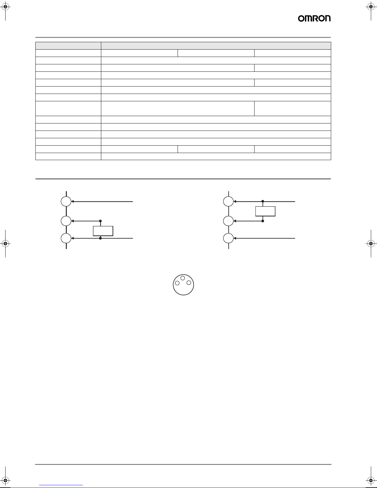
Output Circuit Diagram
PNP NPN
Brown
10 to 35VDC
1
Brown
10 to 35VDC
1
Load
Black
4
Load
Blue
3
0V
M8 connector
(3 pin)
Pin Arrangement
4
3
1
Black
4
Blue
3
0V
2 Photoelectric Sensors
Page 3

Dimensions
M8
L-ON/D-ON
Sensitivity
adjuster
Operation LED
(yellow)
E3U-GS5_
E3U-GS8_
M8
Operation LED
(yellow)
L-ON/D-ON
Sensitivity
adjuster
3E3U-GS_-S
Page 4

E3U-GS12_
3060
100
Operation
LED
(yellow)
22
10
M8
12
62
52
37
10
10 12
Ø4,3
120
5
20
Sensitivity
adjuster
L-ON/D-ON
4 Photoelectric Sensors
Page 5

Safety precautions
! Warning
This product is not designed or rated for directly or
indirectly ensuring safety of persons. Do not use it for
such a purpose.
! Caution
Do not use the product with voltage in excess of the
rated voltage. Excess voltage may result in malfunction or fire.
Never use the product with an AC power supply.
Otherwise, explosion may result.
When cleaning the product, do not apply a high-pressure spray of water to one part of the product. Otherwise, parts may become damaged and the degree of
protection may be degraded.
High-temperature environments may result in burn
injury.
Precautions for Safe Use
The following precautions must be observed to ensure safe
operation of the Sensor.
Operating Environment
Do not use the Sensor in an environment where explosive or
flammable gas is present.
Connecting Connectors
Be sure to hold the connector cover when inserting or removing
the connector. Be sure to tighten the connector lock by hand;
do not use pliers or other tools. If the tightening is insufficient, the
degree of protection will not be maintained and the Sensor may
become loose due to vibration. The appropriate tightening torque
is 0.4 to 0.5 N·m for M12 connectors and 0.3 Nm for M8 connectors.
Load
Do not use a load that exceeds the rated load.
Modifications
Do not attempt to disassemble, repair, or modify the Sensor.
Outdoor Use
Do not use the Sensor in locations subject to direct sunlight.
Surface Temperature
Burn injury may occur. The Sensor surface temperature rises depending on application conditions, such as the surrounding temperature and the power supply voltage. Use caution when
operating or washing the Sensor.
Precautions for Correct Use
Do not use the Sensor in any atmosphere or environment that
exceeds the ratings.
Do not install the Sensor in the following locations.
(1)Locations subject to direct sunlight
(2)Locations subject to condensation due to high humidity
(3)Locations subject to corrosive gas
(4)Locations where the Sensor may receive direct vibration or
shock
Connecting and Mounting
(1)The maximum power supply voltage is 35 VDC. Before turning
the power ON, make sure that the power supply voltage does
not exceed the maximum voltage.
(2)Laying Sensor wiring in the same conduit or duct as high-volt-
age wires or power lines may result in malfunction or damage
due to induction. As a general rule, wire the Sensor in a separate conduit or use shielded cable.
(3)Use an extension cable with a minimum thickness of 1 mm
and less than 100 m long.
(4)Do not pull on the cable with excessive force.
(5)Pounding the Sensor with a hammer or other tool during
mounting will impair water resistance.
(6)Mount the Sensor either using a suitable bracket or on a flat
surface.
(7)Be sure to turn OFF the power supply before inserting or re-
moving the connector.
Power Supply
If a commercial switching regulator is used, ground the FG (frame
ground) terminal.
Turning OFF the Power Supply
Output pulses may be generated even when the power supply is
OFF. Therefore, it is recommended to first turn OFF the power
supply for the load or the load line.
Load Short-circuit Protection
This Sensor is equipped with load short-circuit protection, but be
sure to not short circuit the load. Be sure to not use an output current flow that exceeds the rated current.
2
5E3U-GS_-S
Page 6

WARRANTY
In the interest of product improvement, specifications are subject to change without notice.Cat. No. E69E-EN-01
OMRON EUROPE B.V.
Wegalaan 67-69,
NL-2132 JD, Hoofddorp,
The Netherlands
Phone: +31 23 568 13 00
Fax: +31 23 568 13 88
www.industrial.omron.eu
OMRON’s exclusive warranty is that the products are free from defects in materials and workmanship for a period of one year (or other
period if specified) from date of sale by OMRON.
OMRON MAKES NO WARRANTY OR REPRESENTATION, EXPRESS OR IMPLIED, REGARDING NON-INFRINGEMENT, MERCHANTABILITY, OR FITNESS FOR PARTICULAR PURPOSE OF
THE PRODUCTS. ANY BUYER OR USER ACKNOWLEDGES THAT
THE BUYER OR USER ALONE HAS DETERMINED THAT THE
PRODUCTS WILL SUITABLY MEET THE REQUIREMENTS OF
THEIR INTENDED USE. OMRON DISCLAIMS ALL OTHER WARRANTIES, EXPRESS OR IMPLIED.
LIMITATIONS OF LIABILITY
OMRON SHALL NOT BE RESPONSIBLE FOR SPECIAL, INDIRECT, OR CONSEQUENTIAL DAMAGES, LOSS OF PROFITS OR
COMMERCIAL LOSS IN ANY WAY CONNECTED WITH THE
PRODUCTS, WHETHER SUCH CLAIM IS BASED ON CONTRACT,
WARRANTY, NEGLIGENCE, OR STRICT LIABILITY.
In no event shall responsibility of OMRON for any act exceed the individual price of the product on which liability is asserted.
IN NO EVENT SHALL OMRON BE RESPONSIBLE FOR WARRANTY, REPAIR, OR OTHER CLAIMS REGARDING THE PRODUCTS
UNLESS OMRON’S ANALYSIS CONFIRMS THAT THE PRODUCTS WERE PROPERLY HANDLED, STORED, INSTALLED, AND
MAINTAINED AND NOT SUBJECT TO CONTAMINATION, ABUSE,
MISUSE, OR INAPPROPRIATE MODIFICATION OR REPAIR.
SUITABILITY FOR USE
THE PRODUCTS CONTAINED IN THIS DOCUMENT ARE NOT
SAFETY RATED. THEY ARE NOT DESIGNED OR RATED FOR ENSURING SAFETY OF PERSONS, AND SHOULD NOT BE RELIED
UPON AS A SAFETY COMPONENT OR PROTECTIVE DEVICE
FOR SUCH PURPOSES. Please refer to separate catalogs for OMRON's safety rated products.
OMRON shall not be responsible for conformity with any standards,
codes, or regulations that apply to the combination of products in the
customer’s application or use of the product.
At the customer’s request, OMRON will provide applicable third party
certification documents identifying ratings and limitations of use that
apply to the products. This information by itself is not sufficient for a
complete determination of the suitability of the products in combination with the end product, machine, system, or other application or
use.
The following are some examples of applications for which particular
attention must be given. This is not intended to be an exhaustive list
of all possible uses of the products, nor is it intended to imply that the
uses listed may be suitable for the products:
• Outdoor use, uses involving potential chemical contamination or
electrical interference, or conditions or uses not described in this
document.
• Nuclear energy control systems, combustion systems, railroad systems, aviation systems, medical equipment, amusement machines,
vehicles, safety equipment, and installations subject to separate industry or government regulations.
• Systems, machines, and equipment that could present a risk to life
or property.
Please know and observe all prohibitions of use applicable to the
products.
NEVER USE THE PRODUCTS FOR AN APPLICATION INVOLVING
SERIOUS RISK TO LIFE OR PROPERTY WITHOUT ENSURING
THAT THE SYSTEM AS A WHOLE HAS BEEN DESIGNED TO
ADDRESS THE RISKS, AND THAT THE OMRON PRODUCT IS
PROPERLY RATED AND INSTALLED FOR THE INTENDED USE
WITHIN THE OVERALL EQUIPMENT OR SYSTEM.
PERFORMANCE DATA
Performance data given in this document is provided as a guide for
the user in determining suitability and does not constitute a warranty.
It may represent the result of OMRON’s test conditions, and the users
must correlate it to actual application requirements. Actual performance is subject to the OMRON Warranty and Limitations of Liability.
CHANGE IN SPECIFICATIONS
Product specifications and accessories may be changed at any time
based on improvements and other reasons.
It is our practice to change model numbers when published ratings or
features are changed, or when significant construction changes are
made. However, some specifications of the product may be changed
without any notice. When in doubt, special model numbers may be assigned to fix or establish key specifications for your application on
your request. Please consult with your OMRON representative at any
time to confirm actual specifications of purchased products.
DIMENSIONS AND WEIGHTS
Dimensions and weights are nominal and are not to be used for manufacturing purposes, even when tolerances are shown.
ERRORS AND OMISSIONS
The information in this document has been carefully checked and is
believed to be accurate; however, no responsibility is assumed for
clerical, typographical, or proofreading errors, or omissions.
PROGRAMMABLE PRODUCTS
OMRON shall not be responsible for the user’s programming of a programmable product, or any consequence thereof.
6 Photoelectric Sensors
 Loading...