

Page 1
Photoelectric and capacitive label sensors in fork shape housing
Measurement system
Reference
system
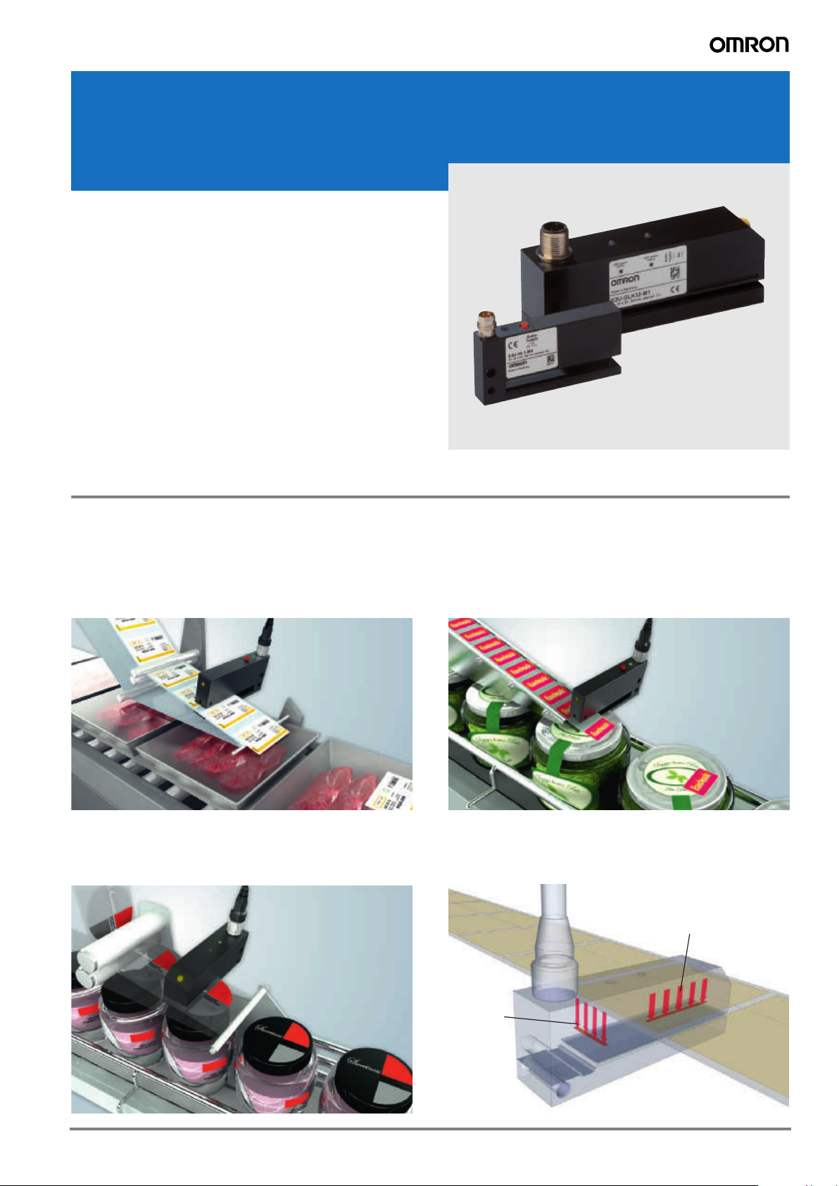
E3U-GL
The E3U-GL range of label sensors offers a solution to detect
all standard as well as challenging labels (e.g. transparent la-
bels with metallized parts). Stable operation, where other sen-
sors may require frequent re-teaching, improves the reliability
of the labeling process. Fast and easy set-up reduces the time
and effort during change over periods.
• Photoelectric sensors for the detection of a wide range of
commonly used labels
• Capacitive sensors for the detection of transparent labels
• Easy manual or remote teach for simple and fast label
change over
• Reliable operation and exact positioning without re-adjust-
ment
Features
Stable operation and quick set-up
Stable operation eliminates the need to re-adjust the sensor
due to temperature changes or other influences during pro-
duction.
The E3U-GL offers quick and easy manual or remote teach-
ing, allowing fast and efficient change overs.
Detection of transparent labels
The E3U-GLK capacitive sensors allow the detection of transparent labels even when partially metallized. The measurement and
reference system ensures a high accuracy and resolution compensating for environmental changes (temperature, humidity,…).
High positional accuracy
The The photoelectric E3U-GL_ label sensors have been me-
chanically designed to allow easy mounting close to the dis-
penser edge. This reduces the potential of positional drift
caused by the carrier film stretching.
1E3U-GL
Page 2
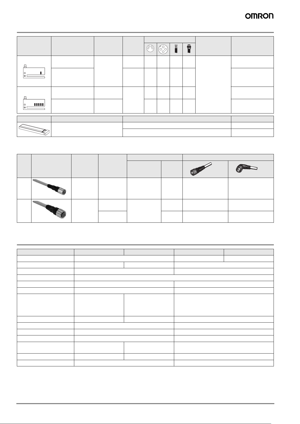
Ordering Information
Sensor type Typical application Sensing
distance
Slot
depth
Connection method Operation mode Order Code
(slot width)
photoelectric
Sensor for standard
labels
Sensor for standard
labels with large slot
5mm
50 mm –––
100 mm –––
Light-on / Darkon selectable
NPN / PNP out
E3U-GL1-M3
E3U-GL2-M3
depth
capacitive Sensor for thin
transparent labels
Sensor for
transparent labels
0.6 mm
1mm
85 mm
– ––
– ––
E3U-GLK31-M1
E3U-GLK32-M1
Shape Type Feature Order Code
Exchangeable bottom part for
E3U-GLK_
For large labels up to 175 mm depth E3U-GLK-EB1
For large labels up to 215 mm depth E3U-GLK-EB2
Accessories
Sensor I/O connectors
Size Shape Type Features Material Order code
Nut Cable
M8 General pur-
pose
(screw)
4 pin Brass (CuZn) PVC 2 m
PUR 2 m
XS3F-M8PVC4S2M
XS3F-M8PUR4S2M
XS3F-M8PVC4A2M
XS3F-M8PUR4A2M
M12 General pur-
3 wire Brass (CuZn) PVC 2 m
pose
(screw)
Note: For the complete list of sensor I/O connectors refer to E26E Accessories datasheet.
4 wire PVC 2 m
PUR 2 m
PUR 2 m
XS2F-M12PVC3S2M
XS2F-M12PUR3S2M
XS2F-M12PVC4S2M
XS2F-M12PUR4S2M
XS2F-M12PVC3A2M
XS2F-M12PUR3A2M
XS2F-M12PVC4A2M
XS2F-M12PUR4A2M
Specifications
Item E3U-GL1 E3U-GL2 E3U-GLK31
*1
E3U-GLK32
Sensing distance (slot width) 5 mm 0,6 mm 1 mm
Slot depth 50 mm 100 mm 85 mm
Sensing method Photoelectric (infrared LED) Capacitive
Power supply voltage 10 to 35 VDC
Power consumption 35 mA 70 mA
Operating frequency 3000 Hz typically 1500 Hz (depending on label material)
Control output Push pull
Load current: 200 mA;
light-on/dark-on selectable
NPN + PNP
Load current: 200 mA;
light-on/dark-on selectable
Push pull
Load current: 200 mA; light-on/dark-on selectable
Sensitivity adjustment Teach-in, remote teach Teach-in Teach-in, remote teach
Ambient illumination 10.000 lx n.a
Ambient temperature -10 to 60°C 0 to 60°C
Degree of protection EN 60529: IP67 EN 60529: IP65
Indicators Status indicator: yellow
Power indicator: green
Status indicator: yellow Status indicator: yellow
Power indicator: green
Weight 50 g 80 g 170 g
Material (case) zinc diecast, black lacquered finish Aluminium, black anodized
*1.
Suitable for label thickness <0.5 mm. The label length and the label interspace must be >2 mm
*2.
Suitable for label thickness <0.9 mm. The label length and the label interspace must be >2 mm
Note: The actual minimum values depend on the combination of material, interspace between labels and label thickness and length.
*2
2 Label Sensors
Page 3
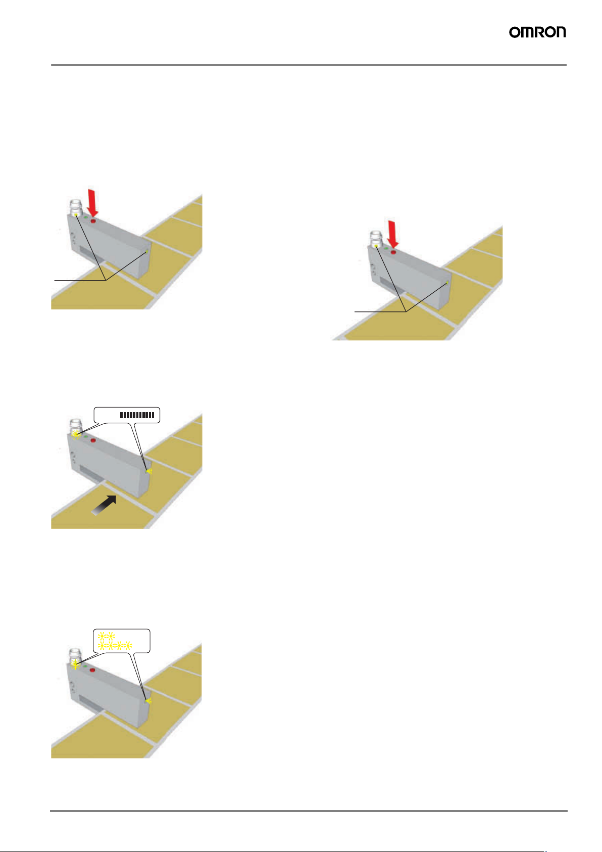
Operation
Status-LED
min. 2 s
For E3U-GL1 For E3U-GL2
2-8 s
min. 2x
1. E3U-GL1 / E3U-GL2
Installation:
Connect the sensor to the operating voltage (+). The Power LED
(green) lights up. Place the label material in the correct position
(the detection beam spot is indicated by marks in the housing).
During the teach process do not remove the label material from
the detection area.
Manual auto-teach:
Press teach key for min. 2 sec., until the yellow Status LED
shows a continuous signal.
The auto-teach procedure is now active indicated by a fast flashing Status LED. Move the labels through the slot. The auto-teaching takes 2-8 seconds depending on the complexity of the labels.
During the auto teach procedure min. 2 labels should be pulled
through. For higher stability the number of labels that are pulled
through should be as high as possible.
Remote auto-teach (E3U-GL1 only):
For remote auto-teach connect pin 2 (white wire) to the operating
voltage (+). The Status LED starts flashing quickly. Move the labels through the slot.
The result of the auto-teach procedure is indicated by the Status
LED as described before.
If pin 2 / white wire is not connected the sensor operates in run
mode.
If pin 2 / white wire is connected to ground the sensor is locked
(no manual auto-teach possible)
Light-on / Dark-on operation
To convert L-On/D-on operation press the teach button for more
than 6 sec.
min. 6 s
Status-LED
For E3U-GL1 For E3U-GL2
The result of the auto-teach procedure is indicated by the Status
LED:
• LED flashing 2x: auto-teach procedure successful. The sensor automatically switches into run mode.
• LED flashing 4x: auto-teach procedure not successful. Repeat the auto-teach procedure.
3E3U-GL
Page 4

2. E3U-GLK3_
2-10 s
min. 2x
min. 2s
Power LED (green)
Status LED (yellow)
Installation
Connect the sensor to the operating voltage (+). The Power LED
(green) lights up. Insert the label material and gently push down.
During the teach process do not remove the label material from
the detection area.
Manual auto-teach:
Press the teach key for min. 2 sec., until the status LED (yellow)
shows a continuous signal.
Exchanging the bottom part for E3U-GLK3_
For the detection of labels using the capacitive sensors E3UGLK3_, it is important that the label is firmly guided by the bottom
part.
To ensure a smooth guiding of larger labels up to 215 mm remove
the pre-mounted bottom part and replace by exchangeable bottom part. For labels up to 175 mm depth use the E3U-GLK-EB1
and for labels up to 215 mm use the E3U-GLK-EB2. Attach the
bottom part again. The maximum mounting torque for the screws
is 0.8 Nm.
Refer to Operating Instructions to teach the sensors again.
The bottom parts are sold separately.
Cleaning
To clean the sensor and the bottom part remove any residues of
labels with a plastic scraper and residues of adhesion with alcohol.
The auto-teach procedure is now active indicated by a fast flashing Status LED. Move the labels through the slot. The auto-teaching takes 2-10 seconds depending on the complexity of the
labels. During the auto teach procedure min. 2 labels should be
pulled through. For higher stability the number of labels that are
pulled through should be as high as possible.
The result of the auto-teach procedure is indicated by the Status
LED and Power LED:
• Status LED and power LED flashing 2x: auto-teach procedure
successful. The sensor automatically switches into run mode.
• Status LED and power LED flashing 4x: Auto-teach procedure not successful. Repeat the auto-teach procedure.
Remote auto-teach:
For remote auto-teach connect pin 2 (white wire) to the operating
voltage (+). The Status LED starts flashing quickly. Move the labels through the slot.
The result of the remote auto-teach procedure is indicated by the
Status LED and Power LED as described before.
If pin2/white wire is not connected the sensor operates in run
mode.
If pin2/white wire is connected to ground the sensor is locked (no
manual auto-teach possible)
4 Label Sensors
Page 5

Output Circuit Diagram
3
1
2
4
M12 Connector Pin Arrangement
E3U-GL1-M3 E3U-GL2-M3
1
2
4
3
E3U-GLK31-M1
E3U-GLK32-M1
1
4
2
3
Brown
White
Black
Blue
Brown
Black
White
Blue
10 to 35VDC
NPN
PNP
0V
10 to 35VDC
NPN
PNP
0V
Te a c h
Lock
Te a c h
Lock
M8 Connector Pin Arrangement
2
4
1
3
Brown
10 to 35VDC
1
NPN
White
2
Black
4
PNP
Blue
3
0V
5E3U-GL
Page 6

Dimensions
Teach
M3 x 10
max. 0,8 Nm
Power LED Status LED
Power LED
Status LED
Tea c h
M3 x 10
max. 0,8 Nm
E3U-GL1-M3 E3U-GL2-M3
M8 x 1
Status LED
yellow
Teach
Power LED
green
E3U-GLK31-M1 E3U-GLK32-M1
29,5
Status LED
M8x1
Teach
11
35
19
5
M5
5
102,5
5
100
120
NO/NC
Status LED
14
28
12
6 Label Sensors
Page 7

Safety precautions
! Warning
This product is not designed or rated for directly or
indirectly ensuring safety of persons. Do not use it for
such a purpose.
! Caution
Do not use the product with voltage in excess of the
rated voltage. Excess voltage may result in malfunction or fire.
Never use the product with an AC power supply.
Otherwise, explosion may result.
When cleaning the product, do not apply a high-pressure spray of water to one part of the product. Otherwise, parts may become damaged and the degree of
protection may be degraded.
High-temperature environments may result in burn
injury.
Precautions for Safe Use
The following precautions must be observed to ensure safe
operation of the Sensor.
Operating Environment
Do not use the Sensor in an environment where explosive or
flammable gas is present.
Connecting Connectors
Be sure to hold the connector cover when inserting or removing
the connector. Be sure to tighten the connector lock by hand;
do not use pliers or other tools. If the tightening is insufficient, the
degree of protection will not be maintained and the Sensor may
become loose due to vibration. The appropriate tightening torque
is 0.4 to 0.5 N·m for M12 connectors and 0.3 Nm for M8 connectors.
Load
Do not use a load that exceeds the rated load.
Environements with Cleaners and Disinfectants
Do not use the Sensor in environments subject to cleaners and
disifectants. They may reduce the degree of protection.
Modifications
Do not attempt to disassemble, repair, or modify the Sensor.
Outdoor Use
Do not use the Sensor in locations subject to direct sunlight.
Surface Temperature
Burn injury may occur. The Sensor surface temperature rises depending on application conditions, such as the surrounding temperature and the power supply voltage. Use caution when
operating or washing the Sensor.
Precautions for Correct Use
Do not use the Sensor in any atmosphere or environment that
exceeds the ratings.
Do not install the Sensor in the following locations.
(1)Locations subject to direct sunlight
(2)Locations subject to condensation due to high humidity
(3)Locations subject to corrosive gas
(4)Locations where the Sensor may receive direct vibration or
shock
Connecting and Mounting
(1)The maximum power supply voltage is 35 VDC. Before turning
the power ON, make sure that the power supply voltage does
not exceed the maximum voltage.
(2)Laying Sensor wiring in the same conduit or duct as high-volt-
age wires or power lines may result in malfunction or damage
due to induction. As a general rule, wire the Sensor in a separate conduit or use shielded cable.
(3)Use an extension cable with a minimum thickness of 1 mm
and less than 100 m long.
(4)Do not pull on the cable with excessive force.
(5)Pounding the Sensor with a hammer or other tool during
mounting will impair water resistance.
(6)Be sure to turn OFF the power supply before inserting or re-
moving the connector.
Power Supply
If a commercial switching regulator is used, ground the FG (frame
ground) terminal.
Turning OFF the Power Supply
Output pulses may be generated even when the power supply is
OFF. Therefore, it is recommended to first turn OFF the power
supply for the load or the load line.
Load Short-circuit Protection
This Sensor is equipped with load short-circuit protection, but be
sure to not short circuit the load. Be sure to not use an output current flow that exceeds the rated current.
Water Resistance
Do not use the Sensor in water, rainfall, or outdoors.
2
7 Label Sensors
Page 8

WARRANTY
In the interest of product improvement, specifications are subject to change without notice.Cat. No. E66E-EN-01
OMRON EUROPE B.V.
Wegalaan 67-69,
NL-2132 JD, Hoofddorp,
The Netherlands
Phone: +31 23 568 13 00
Fax: +31 23 568 13 88
www.industrial.omron.eu
OMRON’s exclusive warranty is that the products are free from defects in materials and workmanship for a period of one year (or other
period if specified) from date of sale by OMRON.
OMRON MAKES NO WARRANTY OR REPRESENTATION, EXPRESS OR IMPLIED, REGARDING NON-INFRINGEMENT, MERCHANTABILITY, OR FITNESS FOR PARTICULAR PURPOSE OF
THE PRODUCTS. ANY BUYER OR USER ACKNOWLEDGES THAT
THE BUYER OR USER ALONE HAS DETERMINED THAT THE
PRODUCTS WILL SUITABLY MEET THE REQUIREMENTS OF
THEIR INTENDED USE. OMRON DISCLAIMS ALL OTHER WARRANTIES, EXPRESS OR IMPLIED.
LIMITATIONS OF LIABILITY
OMRON SHALL NOT BE RESPONSIBLE FOR SPECIAL, INDIRECT, OR CONSEQUENTIAL DAMAGES, LOSS OF PROFITS OR
COMMERCIAL LOSS IN ANY WAY CONNECTED WITH THE
PRODUCTS, WHETHER SUCH CLAIM IS BASED ON CONTRACT,
WARRANTY, NEGLIGENCE, OR STRICT LIABILITY.
In no event shall responsibility of OMRON for any act exceed the individual price of the product on which liability is asserted.
IN NO EVENT SHALL OMRON BE RESPONSIBLE FOR WARRANTY, REPAIR, OR OTHER CLAIMS REGARDING THE PRODUCTS
UNLESS OMRON’S ANALYSIS CONFIRMS THAT THE PRODUCTS WERE PROPERLY HANDLED, STORED, INSTALLED, AND
MAINTAINED AND NOT SUBJECT TO CONTAMINATION, ABUSE,
MISUSE, OR INAPPROPRIATE MODIFICATION OR REPAIR.
SUITABILITY FOR USE
THE PRODUCTS CONTAINED IN THIS DOCUMENT ARE NOT
SAFETY RATED. THEY ARE NOT DESIGNED OR RATED FOR ENSURING SAFETY OF PERSONS, AND SHOULD NOT BE RELIED
UPON AS A SAFETY COMPONENT OR PROTECTIVE DEVICE
FOR SUCH PURPOSES. Please refer to separate catalogs for OMRON's safety rated products.
OMRON shall not be responsible for conformity with any standards,
codes, or regulations that apply to the combination of products in the
customer’s application or use of the product.
At the customer’s request, OMRON will provide applicable third party
certification documents identifying ratings and limitations of use that
apply to the products. This information by itself is not sufficient for a
complete determination of the suitability of the products in combination with the end product, machine, system, or other application or
use.
The following are some examples of applications for which particular
attention must be given. This is not intended to be an exhaustive list
of all possible uses of the products, nor is it intended to imply that the
uses listed may be suitable for the products:
• Outdoor use, uses involving potential chemical contamination or
electrical interference, or conditions or uses not described in this
document.
• Nuclear energy control systems, combustion systems, railroad sys-
tems, aviation systems, medical equipment, amusement machines,
vehicles, safety equipment, and installations subject to separate industry or government regulations.
• Systems, machines, and equipment that could present a risk to life
or property.
Please know and observe all prohibitions of use applicable to the
products.
NEVER USE THE PRODUCTS FOR AN APPLICATION INVOLVING
SERIOUS RISK TO LIFE OR PROPERTY WITHOUT ENSURING
THAT THE SYSTEM AS A WHOLE HAS BEEN DESIGNED TO
ADDRESS THE RISKS, AND THAT THE OMRON PRODUCT IS
PROPERLY RATED AND INSTALLED FOR THE INTENDED USE
WITHIN THE OVERALL EQUIPMENT OR SYSTEM.
PERFORMANCE DATA
Performance data given in this document is provided as a guide for
the user in determining suitability and does not constitute a warranty.
It may represent the result of OMRON’s test conditions, and the users
must correlate it to actual application requirements. Actual performance is subject to the OMRON Warranty and Limitations of Liability.
CHANGE IN SPECIFICATIONS
Product specifications and accessories may be changed at any time
based on improvements and other reasons.
It is our practice to change model numbers when published ratings or
features are changed, or when significant construction changes are
made. However, some specifications of the product may be changed
without any notice. When in doubt, special model numbers may be assigned to fix or establish key specifications for your application on
your request. Please consult with your OMRON representative at any
time to confirm actual specifications of purchased products.
DIMENSIONS AND WEIGHTS
Dimensions and weights are nominal and are not to be used for manufacturing purposes, even when tolerances are shown.
ERRORS AND OMISSIONS
The information in this document has been carefully checked and is
believed to be accurate; however, no responsibility is assumed for
clerical, typographical, or proofreading errors, or omissions.
PROGRAMMABLE PRODUCTS
OMRON shall not be responsible for the user’s programming of a programmable product, or any consequence thereof.
8 Label Sensors
 Loading...