

Omron E3T-ST22, E3T-ST11, E3T-ST13, E3T-ST14, E3T-ST23 Datasheet
...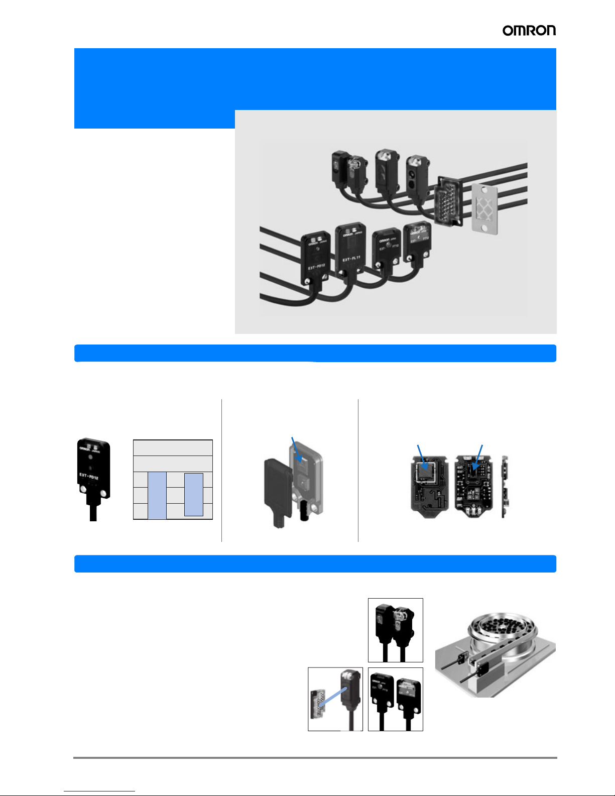
1E3T
Miniature Square Photoelectric Sensor in plastic housing
E3T
• Precision pinpoint LED
• 3.5 mm thin flat shape or 6.6 mm side
view shape where space is crucial
•IP67
• Pulse synchronisation for high
ambient light immunity
Features
3.5 mm flat model with background supression (BGS) with highest repeatability even for differently coloured
objects.
Application
Object detection through small holes
• The precision pinpoint LED of the through-beam models
provides appropriate sensing distances for very precise and
reliable detection even through smallest slits and gaps with
e.g. 0.5 mm dia.
• The coaxial optics and the small focal lens of the
retro-reflective models allow the detection of small
(dia 2 mm) objects or through small holes (dia 2 mm).
Minimal black/white error Unique light receiving lens shape
for high precision alignment
New mounting technology for reliable background
suppression in 3.5 mm flat housing
E3T-FL1@
White paper Black paper
0
5
10
15
20
25
(mm)
Light receiving lens
Rear Front Side
Flip chip (IC)
Light receiving
element
2 Standard Photoelectric Sensors
Application
Ordering Information
Sensors
E3T-SL limited-reflective models (side view)
• Minimum detection object: 0.15 mm dia.
• Limited-reflective optics reduce the influence of changing
backgrounds and surrounding metal for enhanced detection stability.
E3T-FD Diffuse-reflective Models (Flat)
• Minimum detection object: 0.15 mm dia.
• 3.5 mm thickness for installations with limited space.
Sensing
method
Appearance
Connection method
Sensing
distance
Opera-
tion
mode
Order code
NPN output PNP output
Through-
beam
Side-view
--
2m
*1
*1. For pre-wired models with robotic cables add '-R' to the order code (example: E3T-FT21R 2M). For details on robotic cables refer to page 12.
*2
*2. For pre-wired models with M8 connector plug or e-CON connector contact your OMRON representative
Light-ON E3T-ST11 2M E3T-ST13 2M
Dark-ON E3T-ST12 2M E3T-ST14 2M
Light-ON E3T-ST21 2M E3T-ST23 2M
Dark-ON E3T-ST22 2M E3T-ST24 2M
Flat
Light-ON E3T-FT11 2M E3T-FT13 2M
Dark-ON E3T-FT12 2M E3T-FT14 2M
Light-ON E3T-FT21 2M E3T-FT23 2M
Dark-ON E3T-FT22 2M E3T-FT24 2M
Retro-
reflective
Side-view
*3
*3. Values in parentheses indicate the minimum required sensing distance between the sensor and the reflector. For applications with shorter distances between the
sensor and the reflector contact your OMRON representative.
Light-ON E3T-SR41-C 2M*4E3T-SR43-C 2M
*4
*4. Order reflector separately. For ordering models with included reflectors contact your OMRON representative.
Dark-ON E3T-SR42-C 2M*4E3T-SR44-C 2M
*4
Diffuse-
reflective
Flat
Light-ON E3T-FD11 2M E3T-FD13 2M
Dark-ON E3T-FD12 2M E3T-FD14 2M
Limited-
reflective
Side-view
Light-ON E3T-SL11 2M E3T-SL13 2M
Dark-ON E3T-SL12 2M E3T-SL14 2M
Light-ON E3T-SL21 2M E3T-SL23 2M
Dark-ON E3T-SL22 2M E3T-SL24 2M
Diffuse
reflective
(background
suppression)
Flat
Light-ON E3T-FL11 2M E3T-FL13 2M
Dark-ON E3T-FL12 2M E3T-FL14 2M
Light-ON E3T-FL21 2M E3T-FL23 2M
Dark-ON E3T-FL22 2M E3T-FL24 2M
Red light
1 m
(Sensitivity Adjustment
Unit can be used.)
300 mm
500mm
300 mm
200 mm
[30 mm]
100 mm
[10 mm]
5 to 30 mm
5 to 15 mm
5 to 30 mm
1 to 15 mm
1 to 30 mm
3E3T
Accessories (Order Separately)
Slits
Reflectors
Sensitivity Adjustment Unit
Mounting Brackets
Note: When using Through-beam models, order one bracket for the Receiver and one for the Emitter.
Slit width
Sensing distance
(typical)
Minimum detect-
able object (typical)
Order code Quantity Remarks
0.5 mm dia. 100 mm 0.5 mm dia.
E39-S63
2
(one each for
emitter and
receiver)
Plug-in type round slits
Can be used with E3T-ST1@
Through-beam models.
1 mm dia. 300 mm 1 mm dia.
0.5 mm dia. 50 mm 0.5 mm dia.
E39-S64
Plug-in type round slits
Can be used with E3T-FT1@
Through-beam models.
1 mm dia. 100 mm 1 mm dia.
Shape Type Sensing distance
*1
*1. Values in parentheses indicate the minimum required distance between the Sensor and Reflector.
Minimum detectable
object (typical)
Order code Remarks
Small
reflector
200 mm (30 mm) 2 mm dia E39-R4
100 mm (10 mm) E39-R37-CA Reflectors E39-_-CA are optimised
for operation with E3T-SR4. Please
verify the performance when using
other reflectors and reflective tapes.
Tape
reflector
100 mm (10 mm) E39-RS1-CA
100 mm (10 mm) E39-RS2-CA
100 mm (10 mm) E39-RS3-CA
Appearance Sensing distance (typical) Model Quantity Remarks
300 to 800 mm E39-E10 1
Can be used with the E3T-ST1@
Though-beam Models.
Appearance Model Quantity Remarks
E39-L116
1
Can be used with the E3T-S@@@
Side-view Models.
(A securing nut plate is provided with the
Mounting Bracket.)
E39-L117
E39-L118
E39-L119
Can be used with the E3T-F@@@
Flat Models.
E39-L120

4 Standard Photoelectric Sensors
Rating and Specifications
Item
Through-beam Retro-reflective Diffuse-reflective
Side-view Flat Side-view Flat
NPN PNP NPN PNP NPN PNP NPN PNP
E3T-ST11
E3T-ST12
E3T-ST21
E3T-ST22
E3T-ST13
E3T-ST14
E3T-ST23
E3T-ST24
E3T-FT11
E3T-FT12
E3T-FT21
E3T-FT22
E3T-FT13
E3T-FT14
E3T-FT23
E3T-FT24
E3T-SR41
E3T-SR42
E3T-SR43
E3T-SR44
E3T-FD11
E3T-FD12
E3T-FD13
E3T-FD14
Sensing distance E3T-ST1@
E3T-ST2@
1 m
300 mm
E3T-FT1@
E3T-FT2@
500 mm
300 mm
200 mm (30 mm)
with E39-R4
*1
100 mm (10 mm)
with E39-R37-CA
*1
*1. Values in parentheses indicate the minimum required distance between Sensor and Reflector.
5 to 30 mm
(50 x 50 mm white paper)
Standard sensing object Opaque, 2 mm dia. min. Opaque, 1.3 mm dia. min. Opaque, 27 mm dia. min. ---
Minimum detectable
object (typical)
2 mm dia opaque object 1.3 mm dia opaque object 2 mm dia. (sensing dis-
tance of 100 mm)
0.15 mm dia. (sensing
distance of 10 mm)
Hysteresis (white paper) --- 6 mm max.
Black/white error ---
Directional angle Emitter: 2° to 20°
Receiver: 2° to 70°
Emitter: 3° to 25°
Receiver: 3° min.
2° to 20° ---
Light source
(wavelength)
Red LED (“Pin-point” LED) λ = 650 nm
Power supply voltage 12 to 24 VDC ±10%, ripple (p-p) 10% max.
Current consumption Emitter: 10 mA max.
Receiver: 20 mA max.
20 mA max.
Control output Load power supply voltage: 26.4 VDC max.
Load current: 50 mA max.
(residual voltage: 2 V max. for load current of 10 to 50 mA, 1 V max. for load current of less than 10 mA)
Open collector output
Light ON: E3T-@@@1 and E3T-@@@3
Dark ON: E3T-@@@2 and E3T-@@@4
Protection circuits Power supply and control output reverse polarity
protection
Output short-circuit protection
Power supply and control
output reverse polarity
protection
Output short-circuit protection, Mutual interreference prevention, surge
suppressor
Power supply and control
output reverse polarity
protection
Output short-circuit protection, Mutual interreference prevention
Response time Operate or reset: 1 ms max.
Ambient illumination Incandescent lamp: 5,000 lx max.
Sunlight: 10,000 lx max.
Ambient temperature
range
Operating: -25 to 55 °C
Storage: -40 to 70 °C (with no icing or condensation)
Ambient humidity range Operating: 35% to 85%
Storage: 35% to 95% (with no condensation)
Insulation resistance 20 MΩ min. at 500 VDC
Dielectric strength 1,000 VAC, 50/60 Hz for 1 min
Vibration resistance Destruction: 10 to 2,000 Hz, 1.5 mm double amplitude or 300 m/s2 for 0.5 hrs each in X, Y, and Z directions
Shock resistance Destruction: 1,000 m/s2 3 times each in X, Y, and Z directions
Degree of protection IP67 (IEC60529)
Connection method Pre-wired (standard length: 2 m)
Weight Approx. 40 g Approx. 20 g
Materials Case PBT (polybutylene terephthalate)
Display
window
Denatured polyarylate
Lens Denatured polyarylate Methacrylic resin Denatured polyarylate
Accessories Instruction manual, Installation screws (Side-view Models: M2 x 14, Flat Models: M2 x 8), Nuts,
Spring washers, Flat washers

5E3T
Item
Limited-reflective Diffuse-reflective (background suppression)
Side-view Flat
NPN PNP NPN PNP NPN PNP NPN PNP
E3T-SL11
E3T-SL12
E3T-SL13
E3T-SL14
E3T-SL21
E3T-SL22
E3T-SL23
E3T-SL24
E3T-FL11
E3T-FL12
E3T-FL13
E3T-FL14
E3T-FL21
E3T-FL22
E3T-FL23
E3T-FL24
Sensing distance 5 to 15 mm
(50 x 50 mm white paper)
5 to 30 mm
(50 x 50 mm white paper)
1 to 15 mm
(50 x 50 mm white paper)
1 to 30 mm
(50 x 50 mm white paper)
Standard sensing object ---
Minimum detectable
object (typical)
0.15 mm dia. (sensing distance of 10 mm) 0.15 mm dia non-glossy object
(sensing distance of 10 mm)
Hysteresis
(white paper)
2 mm max. 6 mm max. 0.5 mm max. 2 mm max.
Black/white error --- 15% max.
Directional angle ---
Light source
(wavelength)
Red LED (“Pin-point” LED) λ = 650 nm
Power supply voltage 12 to 24 VDC ±10%, ripple (p-p) 10% max.
Current consumption 20 mA max.
Control output Load power supply voltage: 26.4 VDC max.
Load current: 50 mA max. (residual voltage: 2 V max. for load current of 10 to 50 mA, 1 V max. for load current
of less than 10 mA)
Open-collector output
Light ON: E3T-@@@1 and E3T-@@@3
Dark ON: E3T-@@@2 and E3T-@@@4
Protection circuits Power supply and control output reverse polarity protection
Output short-circuit protection, Mutual interference prevention
Response time Operate or reset: 1 ms max.
Ambient illumination Incandescent lamp: 5,000 lx max.
Sunlight: 10,000 lx max.
Ambient temperature
range
Operating: -25 to 55 °C
Storage: -40 to 70 °C (with no icing or condensation)
Ambient humidity range Operating: 35% to 85%
Storage: 35% to 95% (with no condensation)
Insulation resistance 20 MΩ min. at 500 VDC
Dielectric strength 1,000 VAC, 50/60 Hz for 1 min
Vibration resistance Destruction: 10 to 2,000 Hz, 1.5 mm double amplitude or 300 m/s2 for 0.5 hrs each in X, Y, and Z directions
Shock resistance Destruction: 1,000 m/s2 3 times each in X, Y, and Z directions
Degree of protection IP67 (IEC60529)
Connection method Pre-wired (standard length: 2 m)
Weight Approx. 20 g
Materials Case PBT (polybutylene terephthalate)
Display
window
Denatured polyarylate
Lens Denatured polyarylate
Accessories Instruction manual, Installation screws (Side-view Models: M2 x 14, Flat Models: M2 x 8), Nuts,
Spring washers, Flat washers
6 Standard Photoelectric Sensors
Engineering Data (Typical)
Parallel Operating Range
Through-beam
E3T-ST1@ + E39-S63 Slit
(Order Separately)
E3T-ST1@ + E39-S63 Slit
(Order Separately)
(Enlarged graph)
E3T-ST2@
E3T-FT1@ + E39-S64 Slit
(Order Separately)
E3T-FT1@ + E39-S64 Slit
(Order Separately)
(Enlarged graph)
E3T-FT2@
Retro-reflective
E3T-SR4@
200
150
100
50
0
50
100
150
200
0.5-dia Slit
Distance X (m)
1-dia Slit
0.4 0.8 1.2 1.6 1.2
Distance Y (mm)
Without Slit
Y
X
80
60
40
20
0
20
40
60
80
40 80 120 160 200
Distance Y (mm)
1-dia Slit
0.5-dia Slit
Distance X (mm)
Y
X
Y
X
20
15
10
5
0
5
10
15
20
25
25
200 400 800600
Without Slit
Distance X (mm)
Distance Y (mm)
1-dia Slit
0.5-dia Slit
200
150
100
50
0
50
100
150
200
0.4 0.6 0.8 1 1.2 1.40.2
1-dia Slit
Without Slit
Distance X (m)
Y
X
Distance Y (mm)
0.5-dia Slit
80
60
40
20
0
20
40
60
80
40 80 120 160 200
Distance Y (mm)
0.5-dia Slit
1-dia Slit
Distance X (mm)
Y
X
Y
X
60
40
20
0
20
40
60
80
80
200 400 600
800
1-dia Slit
Distance X
(mm)
Distance Y (mm)
Without Slit
0.5-dia Slit
Distance X (mm)
40
30
20
10
0
−10
−20
−30
−40
Distance Y (mm)
100 4000 300200
Y
X
E3T- SR4@+E39-R37-CA
E3T- SR4@+E39-R4
 Loading...