

Page 1
1E3T
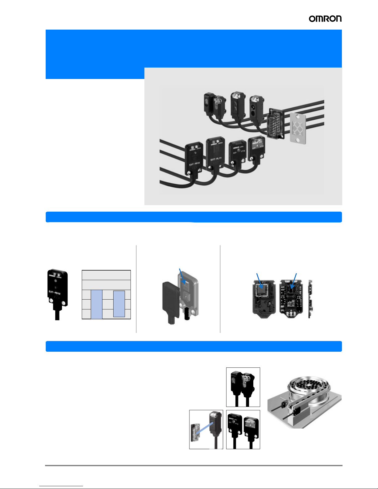
Miniature Square Photoelectric Sensor in plastic housing
E3T
• Precision pinpoint LED
• 3.5 mm thin flat shape or 6.6 mm side
view shape where space is crucial
•IP67
• Pulse synchronisation for high
ambient light immunity
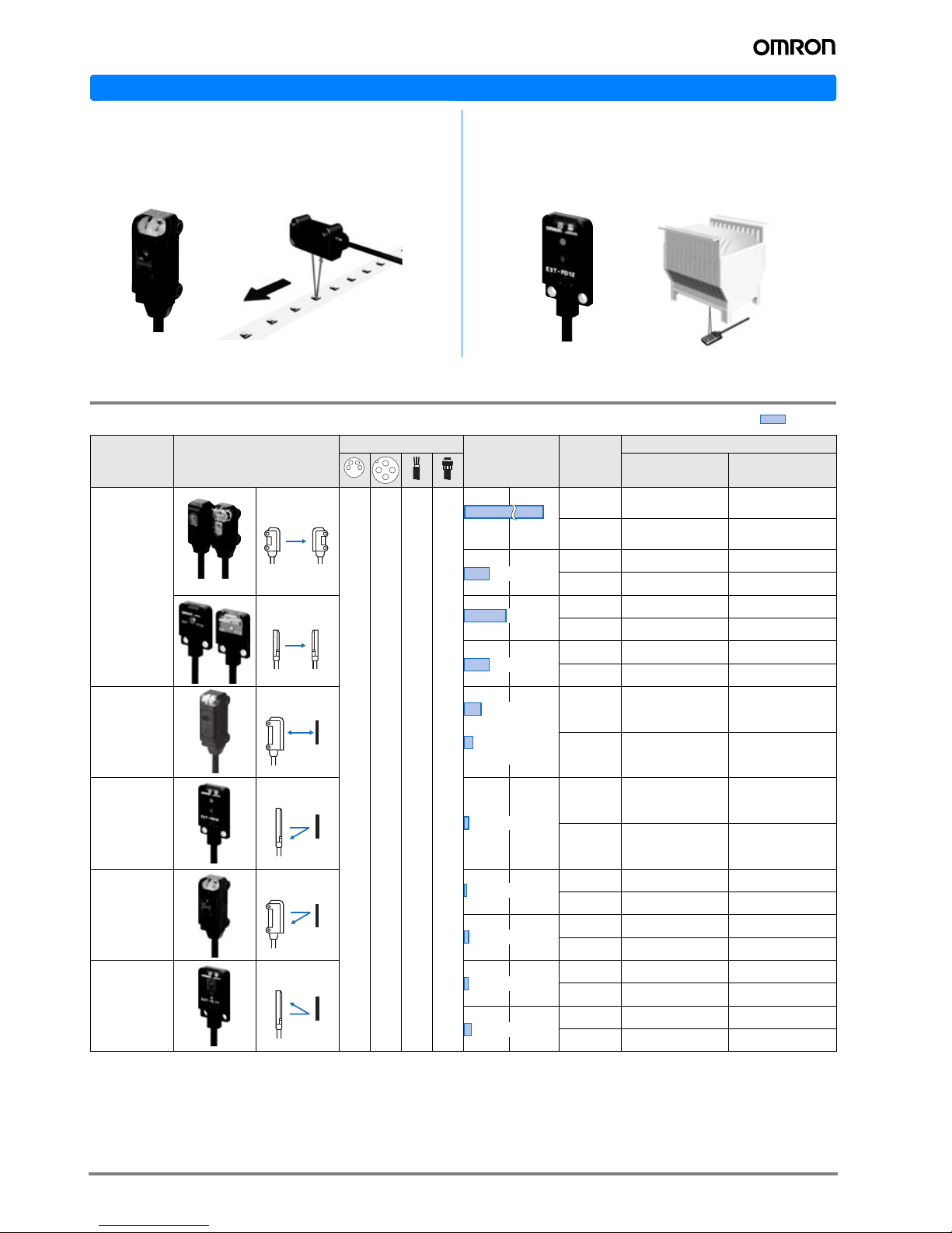
Features
3.5 mm flat model with background supression (BGS) with highest repeatability even for differently coloured
objects.
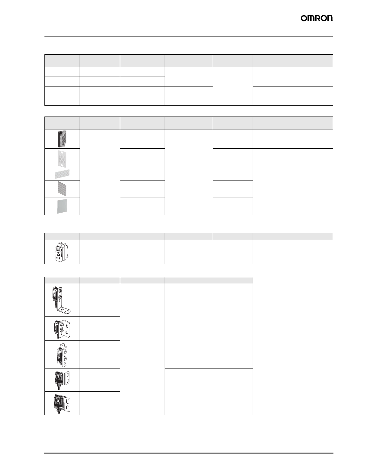
Application
Object detection through small holes
• The precision pinpoint LED of the through-beam models
provides appropriate sensing distances for very precise and
reliable detection even through smallest slits and gaps with
e.g. 0.5 mm dia.
• The coaxial optics and the small focal lens of the
retro-reflective models allow the detection of small
(dia 2 mm) objects or through small holes (dia 2 mm).
Minimal black/white error Unique light receiving lens shape
for high precision alignment
New mounting technology for reliable background
suppression in 3.5 mm flat housing
E3T-FL1@
White paper Black paper
0
5
10
15
20
25
(mm)
Light receiving lens
Rear Front Side
Flip chip (IC)
Light receiving
element
Page 2
2 Standard Photoelectric Sensors
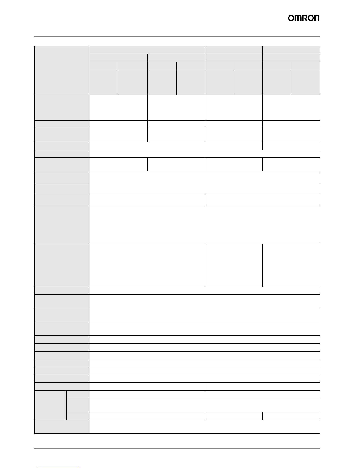
Application
Ordering Information
Sensors
E3T-SL limited-reflective models (side view)
• Minimum detection object: 0.15 mm dia.
• Limited-reflective optics reduce the influence of changing
backgrounds and surrounding metal for enhanced detection stability.
E3T-FD Diffuse-reflective Models (Flat)
• Minimum detection object: 0.15 mm dia.
• 3.5 mm thickness for installations with limited space.
Sensing
method
Appearance
Connection method
Sensing
distance
Opera-
tion
mode
Order code
NPN output PNP output
Through-
beam
Side-view
--
2m
*1
*1. For pre-wired models with robotic cables add '-R' to the order code (example: E3T-FT21R 2M). For details on robotic cables refer to page 12.
*2
*2. For pre-wired models with M8 connector plug or e-CON connector contact your OMRON representative
Light-ON E3T-ST11 2M E3T-ST13 2M
Dark-ON E3T-ST12 2M E3T-ST14 2M
Light-ON E3T-ST21 2M E3T-ST23 2M
Dark-ON E3T-ST22 2M E3T-ST24 2M
Flat
Light-ON E3T-FT11 2M E3T-FT13 2M
Dark-ON E3T-FT12 2M E3T-FT14 2M
Light-ON E3T-FT21 2M E3T-FT23 2M
Dark-ON E3T-FT22 2M E3T-FT24 2M
Retro-
reflective
Side-view
*3
*3. Values in parentheses indicate the minimum required sensing distance between the sensor and the reflector. For applications with shorter distances between the
sensor and the reflector contact your OMRON representative.
Light-ON E3T-SR41-C 2M*4E3T-SR43-C 2M
*4
*4. Order reflector separately. For ordering models with included reflectors contact your OMRON representative.
Dark-ON E3T-SR42-C 2M*4E3T-SR44-C 2M
*4
Diffuse-
reflective
Flat
Light-ON E3T-FD11 2M E3T-FD13 2M
Dark-ON E3T-FD12 2M E3T-FD14 2M
Limited-
reflective
Side-view
Light-ON E3T-SL11 2M E3T-SL13 2M
Dark-ON E3T-SL12 2M E3T-SL14 2M
Light-ON E3T-SL21 2M E3T-SL23 2M
Dark-ON E3T-SL22 2M E3T-SL24 2M
Diffuse
reflective
(background
suppression)
Flat
Light-ON E3T-FL11 2M E3T-FL13 2M
Dark-ON E3T-FL12 2M E3T-FL14 2M
Light-ON E3T-FL21 2M E3T-FL23 2M
Dark-ON E3T-FL22 2M E3T-FL24 2M
Red light
1 m
(Sensitivity Adjustment
Unit can be used.)
300 mm
500mm
300 mm
200 mm
[30 mm]
100 mm
[10 mm]
5 to 30 mm
5 to 15 mm
5 to 30 mm
1 to 15 mm
1 to 30 mm
Page 3
3E3T
Accessories (Order Separately)
Slits
Reflectors
Sensitivity Adjustment Unit
Mounting Brackets
Note: When using Through-beam models, order one bracket for the Receiver and one for the Emitter.
Slit width
Sensing distance
(typical)
Minimum detect-
able object (typical)
Order code Quantity Remarks
0.5 mm dia. 100 mm 0.5 mm dia.
E39-S63
2
(one each for
emitter and
receiver)
Plug-in type round slits
Can be used with E3T-ST1@
Through-beam models.
1 mm dia. 300 mm 1 mm dia.
0.5 mm dia. 50 mm 0.5 mm dia.
E39-S64
Plug-in type round slits
Can be used with E3T-FT1@
Through-beam models.
1 mm dia. 100 mm 1 mm dia.
Shape Type Sensing distance
*1
*1. Values in parentheses indicate the minimum required distance between the Sensor and Reflector.
Minimum detectable
object (typical)
Order code Remarks
Small
reflector
200 mm (30 mm) 2 mm dia E39-R4
100 mm (10 mm) E39-R37-CA Reflectors E39-_-CA are optimised
for operation with E3T-SR4. Please
verify the performance when using
other reflectors and reflective tapes.
Tape
reflector
100 mm (10 mm) E39-RS1-CA
100 mm (10 mm) E39-RS2-CA
100 mm (10 mm) E39-RS3-CA
Appearance Sensing distance (typical) Model Quantity Remarks
300 to 800 mm E39-E10 1
Can be used with the E3T-ST1@
Though-beam Models.
Appearance Model Quantity Remarks
E39-L116
1
Can be used with the E3T-S@@@
Side-view Models.
(A securing nut plate is provided with the
Mounting Bracket.)
E39-L117
E39-L118
E39-L119
Can be used with the E3T-F@@@
Flat Models.
E39-L120
Page 4
4 Standard Photoelectric Sensors
Rating and Specifications
Item
Through-beam Retro-reflective Diffuse-reflective
Side-view Flat Side-view Flat
NPN PNP NPN PNP NPN PNP NPN PNP
E3T-ST11
E3T-ST12
E3T-ST21
E3T-ST22
E3T-ST13
E3T-ST14
E3T-ST23
E3T-ST24
E3T-FT11
E3T-FT12
E3T-FT21
E3T-FT22
E3T-FT13
E3T-FT14
E3T-FT23
E3T-FT24
E3T-SR41
E3T-SR42
E3T-SR43
E3T-SR44
E3T-FD11
E3T-FD12
E3T-FD13
E3T-FD14
Sensing distance E3T-ST1@
E3T-ST2@
1 m
300 mm
E3T-FT1@
E3T-FT2@
500 mm
300 mm
200 mm (30 mm)
with E39-R4
*1
100 mm (10 mm)
with E39-R37-CA
*1
*1. Values in parentheses indicate the minimum required distance between Sensor and Reflector.
5 to 30 mm
(50 x 50 mm white paper)
Standard sensing object Opaque, 2 mm dia. min. Opaque, 1.3 mm dia. min. Opaque, 27 mm dia. min. ---
Minimum detectable
object (typical)
2 mm dia opaque object 1.3 mm dia opaque object 2 mm dia. (sensing dis-
tance of 100 mm)
0.15 mm dia. (sensing
distance of 10 mm)
Hysteresis (white paper) --- 6 mm max.
Black/white error ---
Directional angle Emitter: 2° to 20°
Receiver: 2° to 70°
Emitter: 3° to 25°
Receiver: 3° min.
2° to 20° ---
Light source
(wavelength)
Red LED (“Pin-point” LED) λ = 650 nm
Power supply voltage 12 to 24 VDC ±10%, ripple (p-p) 10% max.
Current consumption Emitter: 10 mA max.
Receiver: 20 mA max.
20 mA max.
Control output Load power supply voltage: 26.4 VDC max.
Load current: 50 mA max.
(residual voltage: 2 V max. for load current of 10 to 50 mA, 1 V max. for load current of less than 10 mA)
Open collector output
Light ON: E3T-@@@1 and E3T-@@@3
Dark ON: E3T-@@@2 and E3T-@@@4
Protection circuits Power supply and control output reverse polarity
protection
Output short-circuit protection
Power supply and control
output reverse polarity
protection
Output short-circuit protection, Mutual interreference prevention, surge
suppressor
Power supply and control
output reverse polarity
protection
Output short-circuit protection, Mutual interreference prevention
Response time Operate or reset: 1 ms max.
Ambient illumination Incandescent lamp: 5,000 lx max.
Sunlight: 10,000 lx max.
Ambient temperature
range
Operating: -25 to 55 °C
Storage: -40 to 70 °C (with no icing or condensation)
Ambient humidity range Operating: 35% to 85%
Storage: 35% to 95% (with no condensation)
Insulation resistance 20 MΩ min. at 500 VDC
Dielectric strength 1,000 VAC, 50/60 Hz for 1 min
Vibration resistance Destruction: 10 to 2,000 Hz, 1.5 mm double amplitude or 300 m/s2 for 0.5 hrs each in X, Y, and Z directions
Shock resistance Destruction: 1,000 m/s2 3 times each in X, Y, and Z directions
Degree of protection IP67 (IEC60529)
Connection method Pre-wired (standard length: 2 m)
Weight Approx. 40 g Approx. 20 g
Materials Case PBT (polybutylene terephthalate)
Display
window
Denatured polyarylate
Lens Denatured polyarylate Methacrylic resin Denatured polyarylate
Accessories Instruction manual, Installation screws (Side-view Models: M2 x 14, Flat Models: M2 x 8), Nuts,
Spring washers, Flat washers
Page 5

5E3T
Item
Limited-reflective Diffuse-reflective (background suppression)
Side-view Flat
NPN PNP NPN PNP NPN PNP NPN PNP
E3T-SL11
E3T-SL12
E3T-SL13
E3T-SL14
E3T-SL21
E3T-SL22
E3T-SL23
E3T-SL24
E3T-FL11
E3T-FL12
E3T-FL13
E3T-FL14
E3T-FL21
E3T-FL22
E3T-FL23
E3T-FL24
Sensing distance 5 to 15 mm
(50 x 50 mm white paper)
5 to 30 mm
(50 x 50 mm white paper)
1 to 15 mm
(50 x 50 mm white paper)
1 to 30 mm
(50 x 50 mm white paper)
Standard sensing object ---
Minimum detectable
object (typical)
0.15 mm dia. (sensing distance of 10 mm) 0.15 mm dia non-glossy object
(sensing distance of 10 mm)
Hysteresis
(white paper)
2 mm max. 6 mm max. 0.5 mm max. 2 mm max.
Black/white error --- 15% max.
Directional angle ---
Light source
(wavelength)
Red LED (“Pin-point” LED) λ = 650 nm
Power supply voltage 12 to 24 VDC ±10%, ripple (p-p) 10% max.
Current consumption 20 mA max.
Control output Load power supply voltage: 26.4 VDC max.
Load current: 50 mA max. (residual voltage: 2 V max. for load current of 10 to 50 mA, 1 V max. for load current
of less than 10 mA)
Open-collector output
Light ON: E3T-@@@1 and E3T-@@@3
Dark ON: E3T-@@@2 and E3T-@@@4
Protection circuits Power supply and control output reverse polarity protection
Output short-circuit protection, Mutual interference prevention
Response time Operate or reset: 1 ms max.
Ambient illumination Incandescent lamp: 5,000 lx max.
Sunlight: 10,000 lx max.
Ambient temperature
range
Operating: -25 to 55 °C
Storage: -40 to 70 °C (with no icing or condensation)
Ambient humidity range Operating: 35% to 85%
Storage: 35% to 95% (with no condensation)
Insulation resistance 20 MΩ min. at 500 VDC
Dielectric strength 1,000 VAC, 50/60 Hz for 1 min
Vibration resistance Destruction: 10 to 2,000 Hz, 1.5 mm double amplitude or 300 m/s2 for 0.5 hrs each in X, Y, and Z directions
Shock resistance Destruction: 1,000 m/s2 3 times each in X, Y, and Z directions
Degree of protection IP67 (IEC60529)
Connection method Pre-wired (standard length: 2 m)
Weight Approx. 20 g
Materials Case PBT (polybutylene terephthalate)
Display
window
Denatured polyarylate
Lens Denatured polyarylate
Accessories Instruction manual, Installation screws (Side-view Models: M2 x 14, Flat Models: M2 x 8), Nuts,
Spring washers, Flat washers
Page 6
6 Standard Photoelectric Sensors
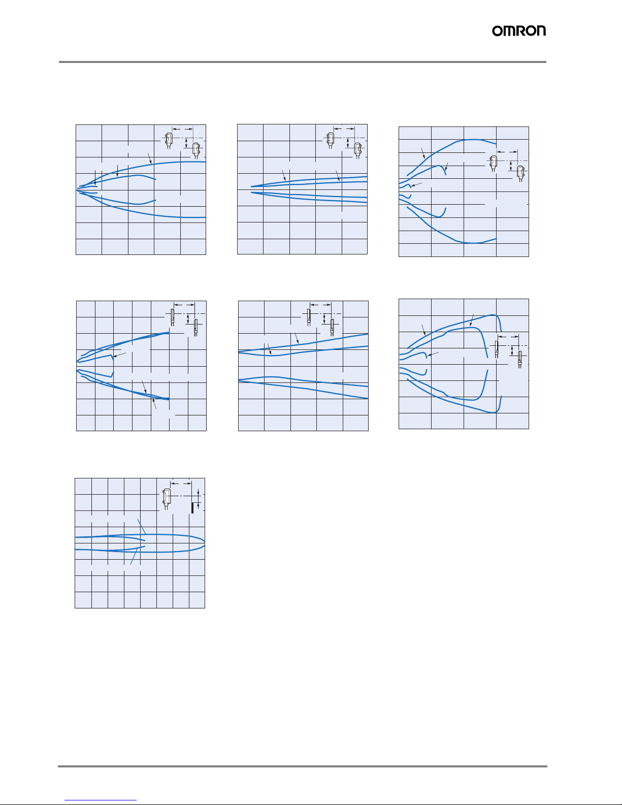
Engineering Data (Typical)
Parallel Operating Range
Through-beam
E3T-ST1@ + E39-S63 Slit
(Order Separately)
E3T-ST1@ + E39-S63 Slit
(Order Separately)
(Enlarged graph)
E3T-ST2@
E3T-FT1@ + E39-S64 Slit
(Order Separately)
E3T-FT1@ + E39-S64 Slit
(Order Separately)
(Enlarged graph)
E3T-FT2@
Retro-reflective
E3T-SR4@
200
150
100
50
0
50
100
150
200
0.5-dia Slit
Distance X (m)
1-dia Slit
0.4 0.8 1.2 1.6 1.2
Distance Y (mm)
Without Slit
Y
X
80
60
40
20
0
20
40
60
80
40 80 120 160 200
Distance Y (mm)
1-dia Slit
0.5-dia Slit
Distance X (mm)
Y
X
Y
X
20
15
10
5
0
5
10
15
20
25
25
200 400 800600
Without Slit
Distance X (mm)
Distance Y (mm)
1-dia Slit
0.5-dia Slit
200
150
100
50
0
50
100
150
200
0.4 0.6 0.8 1 1.2 1.40.2
1-dia Slit
Without Slit
Distance X (m)
Y
X
Distance Y (mm)
0.5-dia Slit
80
60
40
20
0
20
40
60
80
40 80 120 160 200
Distance Y (mm)
0.5-dia Slit
1-dia Slit
Distance X (mm)
Y
X
Y
X
60
40
20
0
20
40
60
80
80
200 400 600
800
1-dia Slit
Distance X
(mm)
Distance Y (mm)
Without Slit
0.5-dia Slit
Distance X (mm)
40
30
20
10
0
−10
−20
−30
−40
Distance Y (mm)
100 4000 300200
Y
X
E3T- SR4@+E39-R37-CA
E3T- SR4@+E39-R4
Page 7

7E3T
Operating Range
Inclination Characteristics
Diffuse-reflective Limited-reflective
E3T-FD1@ E3T-SL1@ E3T-SL2@
Diffuse-reflective (background suppression)
E3T-FL1@ E3T-FL2@
Limited-reflective
E3T-SL1@ (Top to Bottom) E3T-SL1@ (Right to Left) E3T-SL2@ (Top to Bottom)
Sensing object:
50 x 50 mm white paper
3
2
1
0
1
2
3
4
4
10 20 30 40
Y
X
Distance Y (mm)
Distance X
(mm)
15
10
5
0
5
10
15
51015202530
Y
X
Distance Y (mm)
Sensing object:
50 x 50 mm white paper
Distance X
(mm)
3
2
1
0
1
2
3
4
4
10 20 30 40
Distance Y (mm)
Sensing object:
50 x 50 mm white paper
Distance X
(mm)
Y
X
4
3
2
1
0
1
2
3
4
5
5
26841012
Sensing distance X (mm)
Distance Y (mm)
14 16
8
6
4
2
0
2
4
6
8
10
10
5152010 25 30 35
Sensing distance X (mm)
Distance Y (mm)
Glass
250
200
150
100
50
0
50
300
100
6020 400204060
Angle (°)
Stainless steel
Angle
of inclination
+
Rate of ch
ange (%)
40
20
0
20
40
60
80
50
100
6020 400204060
+
Glass
Stainless steel
Angle of
inclination
Angle (°)
Rate of ch
ange (%)
250
200
150
100
50
0
50
300
100
6020 400204060
+
Glass
Stainless steel
Angle of
inclination
Angle (°)
Rate of change (%)
Page 8

8 Standard Photoelectric Sensors
Exess Gain vs. Set Distance
Diffuse-reflective (background suppression)
E3T-SL2@ (Right to Left) E3T-FL1@ (Top to Bottom) E3T-FL1@ (Right to Left)
E3T-FL2@ (Top to Bottom) E3T-FL2@ (Right to Left)
Through-beam
E3T-ST1@ E3T-FT1@ E3T-ST2@
40
20
0
20
40
60
80
60
100
6020 400204060
+
Glass
Stainless steel
Angle of
inclination
Rate of ch
ange (%)
Angle of inclination (°
)
15
10
5
0
5
10
15
20
20
402010 30020 103040
Rate of change in sensing distance (%)
Angle of
inclination
White
paper
Center
line
+
Angle of inclination (°)
15
10
5
0
5
10
15
20
20
402010 30020 103040
+
Rate of change in sensing distance (%)
Angle of
inclination
White
paper
Center
line
Angle of inclination (°)
15
10
5
0
5
10
15
20
20
402010 30020 103040
+
Rate of change in sensing distance (%)
Angle of
inclination
White
paper
Center
line
Angle of inclination (°)
15
10
5
0
5
10
15
20
20
402010 30020 103040
+
Rate of change in sensing distance (%)
Angle of
inclination
White
paper
Center
line
Angle of inclination (°)
100
50
30
10
5
3
1
0.5
0.3
0.1
40003000200010000
Excess gain ratio
Operating
level
Set distance (mm)
100
50
30
10
5
3
1
0.5
0.3
0.1
0 400 800 1200 1600 2000
Excess gain ratio
Operating
level
Set distance (mm)
14
12
10
8
6
4
2
0
1
12009006003000
Operating
level
Set distance (mm)
Excess gain ratio
Page 9

9E3T
Sensing Object Size vs. Sensing Distance
Retro-reflective
E3T-FT2@ E3T-SR4@
Diffuse-reflective
Limited-reflective
E3T-FD1@ E3T-SL1@ E3T-SL2@
E3T-SL1@ E3T-FD1@, E3T-SL2@
14
12
10
8
6
4
2
0
2000150010005000
1
Excess gain ratio
Operating
level
Set distance (mm
)
100
50
30
10
5
3
1
0.5
0.3
0.1
Excess gain ratio (times)
3002001000
Distance (mm)
Operating
level
E3T- SR4@+E39-R37-CA
E3T- SR4@+E39-R4
100
50
30
10
5
3
1
0.5
0.3
0.1
0 10 20 30 40
Excess gain ratio
Operating
level
Black paper
White paper
Set distance (mm
)
0 5 10 15 20
1000
500
300
100
50
30
10
5
3
1
0.5
0.3
0.1
Excess gain ratio
Operating
level
Black paper
White paper
Set distance (mm)
100
50
30
10
5
3
1
0.5
0.3
0.1
0 10 20 30 40
Excess gain ratio
Operating
level
White paper
Black paper
Set distance
(mm)
2.0
1.6
1.2
0.8
0.4
0
5 10 15 20
Min. sensing object dia. (mm)
0 5 10 15 20 25 30
10
8
6
4
2
E3T-FD1@
E3T-SL2@
Min. sensing object dia. (mm
)
Sensing object: Pin-gauge, stainless steel
Set distance (mm)
Page 10

10 Standard Photoelectric Sensors
Sensing Distance vs. Material
Sensing Distance Characteristics of Sensitivity Adjustment Unit
(when Completing Optical Axial Adjustment)
Limited-reflective
Diffuse-reflective
E3T-SL1@ E3T-SL2@ E3T-FD1@
Diffuse-reflective (background suppression)
E3T-FL1@ E3T-FL2@
E3T-ST1@ + E39-E10 Sensitivity Adjustment
Unit (Order Serparately)
25
20
15
10
5
0
Material
Sensing distance (mm)
White paper
Stainless
Plywoodood
Cardboard
Glass sheet
Black rubber
Black paper
41,439
50
40
30
20
10
0
Material
Sensing distance (mm)
White paper
Stainless
Plywood
Cardboard
Glass sheet
Black rubber
Black paper
70
60
50
40
30
20
10
0
Material
Sensing distance (mm)
White paper
Stainless
Plywood
Cardboard
Glass sheet
Black rubber
Black paper
20
15
10
5
0
Material
Sensing distance (mm)
White paper
Stainless
Plywood
Cardboard
Glass sheet
Black rubber
Black paper
40
30
20
10
0
Material
Sensing distance (mm)
White paper
Stainless
Plywood
Cardboard
Glass sheet
Black rubber
Black paper
Min. 1/3 1/2 2/3 Max.
Adjustment dial angle
3.5
3.0
2.5
2.0
1.5
1.0
0.5
0
Measurement pattern 2
Measurement pattern 1
Sensing distance (m)
Page 11

11E3T
I/O Circuit Diagrams
NPN Output
PNP Output
Model
Operation
mode
Timing charts Output circuit
E3T-@@@1 Light-ON
E3T-@@@2Dark-ON
Model
Operation
mode
Timing charts Output circuit
E3T-@@@3 Light-ON
E3T-@@@4Dark-ON
Operation
indicator
(orange)
Light incident
Light interrupted
ON
OFF
Output
transistor
ON
OFF
Load
(e.g., relay)
Operate
Reset
(Between brown and black)
4
3
1
50 mA
max.
0 V
Z
D
12 to 24 VDC
Through-beam Receivers,
Retroreflective and Reflective Models
Through-beam Emitters
Brown
Black
(Control
output)
Blue
Operation
indicator
(Orange)
Stability
indicator
(Green)
Load
(Relay)
Photoelectric
Sensor
Main
Circuit
Brown
1
3
Blue
12 to 24 VDC
Photoelectric
Sensor
Main
Circuit
ON
OFF
ON
OFF
Operate
Reset
(Between brown and black)
Operation
indicator
(orange)
Light incident
Light interrupted
Output
transistor
Load
(e.g., relay)
Operation
indicator
(orange)
Light incident
Light interrupted
ON
OFF
Output
transistor
ON
OFF
Load
(e.g., relay)
Operate
Reset
(Between blue and black leads)
4
1
3
50 mA
max.
0 V
Z
D
12 to 24 VDC
Brown
Black
(Control
output)
Blue
Load
(Relay)
Photoelectric
Sensor
Main
Circuit
Operation
indicator
(Orange)
Stability
indicator
(Green)
Through-beam Receivers,
Retroreflective and Reflective Models
1
3
Through-beam Emitters
Brown
Blue
12 to 24 VDC
Photoelectric
Sensor
Main
Circuit
Operation
indicator
(orange)
Light incident
Light interrupted
ON
OFF
Output
transistor
ON
OFF
Load
(e.g., relay)
Operate
Reset
(Between blue and black leads)
Page 12

12 Standard Photoelectric Sensors
Safety Precautions
This product is not designed or rated for ensuring
safety of persons. Do not use it for such purpose.
Do not apply AC power to the E3T, otherwise the
E3T may rupture.
Do not use the product in atmospheres or environment that
exceed product ratings.
Wiring
The maximum power supply voltage is 24 VDC +10%. Before
turning the power ON, make sure that the power supply volt-
age is not more than maximum voltage.
Load short-circuit protection
The E3T incorporates a load short-circuit protection function.
If the load short-circuits, the output of the E3T will be turned
OFF. Then, recheck the wiring and turn on the E3T again to
reset the load short-circuit protection function. The load short-
circuit protection function will work if there is a current flow
that is 2.4 times larger than the rated load current. When us-
ing an inductance load, be sure that the inrush current will not
exceed 2.4 times larger than the rated current.
Mounting
When mounting the Sensor, never strike it with a heavy ob-
ject, such as a hammer. Doing so may reduce its watertight
properties. Use M2 screws and flat or spring washers to se-
cure the Sensor. (Tightening torque: 0.15 N·m max.)
Mounting the Sensor on Moving Parts
Cable Bending Rupture Test
(Tough Cable Breaking Test)
The cable is repeatedly bent with power supplied to check the
number of bends until the current is turned OFF
.
L
Adjusting
Indicators
• The following graphs indicate the status of each operating
level.
• Be sure to use the E3T within the stable operating range.
Use of E39-E10 Sensitivity Adjustment Unit
(Dark-ON: E3T-ST12)
1. Mount the Unit on the Receiver.
2. Set the adjuster of the Sensitivity Adjustment Unit to Max.
(Before shipping: Max.)
3. After mounting on the Sensor, adjust the optical axis and
secure the Sensor.
4. Place a workpiece between the Emitter and Receiver and
gradually turn the adjuster counterclockwise toward the
Min. side. Stop turning the adjuster when the operation indicator and stability indicator (green) turn ON.
5. Remove the workpiece and confirm that the operation in-
dicator is OFF and the stability indicator (green) is ON.
This completes the adjustment.
Note: If the light attenuation rate due to a workpiece is 40% or less, the stability
indicator will not turn ON whether or not light is received. When the variation of light is small such as when sensing semi-transparent workpieces, carefully perform preliminary testing.
Others
Do not install the E3T in the following locations.
• Locations subject to excessive dust or dirt
• Locations subject to direct sunlight
• Locations subject to corrosive gas
• Locations subject to contact with organic solvents
• Locations subject to vibration and shock
• Locations subject to contact with water, oil, or chemicals
• Locations subject to high humidities that might result in
condensation
! Warning
Precautions for Correct Use
Test
Specimen Standard cable
2.4 mm dia. (7/
0.127 mm dia.),
3 conductors
Robotics cable
2.4 mm (20/
0.08 mm dia.),
Test 3 conductors
Con-
tents/
condi-
tions
Bending
angle (θ)
90° each to the left and right
Bending speed 50 times/min
Load 200 g
Operation per
bend
Once in 1 to 3 in the diagram
Curvature radius of support
point (R)
5 mm
Result Approx. 14,000
times
Approx. 400,000
times
Weight
R
A
C
B
Consider models that use break resistant ca-
bles (e.g., Robotics Cables) if the Sensor
will be mounted on a moving part, such
as a robot hand. The flexing resistance of
Robotics Cable at approximately 400 thou-
sand times is far superior to that of standard
cable at approximately 14 thousand times.
Stable
operation
range*
Stable
operation
range*
Unstable
operation
range*
Operating
level x 1.2
Operating
level x 0.8
Operating
level
Light
ON
ON
ON
ON
OFF
OFF
OFF
Stability
indicator
(green)
Operation indicator (orange)
E3T-@@@1
E3T-@@@3
E3T-@@@2
E3T-@@@4
*If the E3T fs operating level is set to the stable operation range, the E3T
will be in most reliable operation without being influenced by temperature
change, voltage fluctuation, dust, or setting change. If the operating level
cannot be set to the stable operation range, pay attention to environmental
changes while operating the E3T.
Indicator
Adjuster
(At Min)
(At Center)
(At Max.)
Page 13

13E3T
Dimensions
Sensors
Two, M2
9
±0.2
Emitter
7
6.6
7.7
R2.5
Two, 2.2 dia.
2.7
9
14.6
18.5
3.8
5.2
4.8
9.5
2.4-dia. vinyl-insulated round cable
with 2 conductors
(Conductor cross section: 0.1 mm²,
Insulator diameter: 0.7 mm),
Standard length: 2 m
2.4-dia. vinyl-insulated round cable
with 3 conductors
(Conductor cross section: 0.1 mm²,
Insulator diameter: 0.7 mm),
Standard length: 2 m
Mounting Holes
Two, M2
±0.2
Receiver
3.1
7
6.6
7.7
R2.5
Two, 2.2 dia.
2.7
9
14.6
18.5
3.8
5.2
4.8
9.5
3.45
Operation
indicator*
Lens (1.3 dia.)
Stability
indicator
Mounting Holes
Through-beam Models
(Side-view)
E3T-ST1@ (Emitter)
E3T-ST2@ (Emitter)
E3T-FT1@ (Emitter)
E3T-FT2@ (Emitter)
E3T-FT1@ (Receiver)
E3T-FT2@ (Receiver)
E3T-ST1@ (Receiver)
E3T-ST2@ (Receiver)
1
15
2
3
4
5.9
15.6
2.4-dia. vinyl-insulated round cable
with 3 conductors
Standard lengths: 0.3 m and 2 m
2.4-dia. vinyl-insulated round cable
with 3 conductors
Standard lengths: 0.3 m and 2 m
e-CON Pre-wired Connector Model
(E3T-ST@@-ECON)
e-CON Pre-wired Connector Model
(E3T-ST@@-ECON)
Terminal
No.
Specifi-
cations
1+V
2 ---
---
3
4
Emitter: E3T-ST@@-L
Receiver: E3T-ST@@-D
1
1
5
2
3
4
5.9
15.6
1+V
2
3
4 Output
8
±0.2
3.5
12
R0.5
R0.5
Two, R0.5
8.6
Two, R0.8
14
15.8
19
1.75
4.4
8
Emitter
Optical axis
Two, 2.2 dia.
Mounting Holes
Two, M2
Through-beam Models (Flat)
1
15
2
3
4
5.9
15.6
1
+V
2
---
3
0 V
4
---
3.5
3.1
12
R0.5
R0.5
Two, R0.5
8.6
2.35
Two, R2
Two, R0.8
14
15.8
19
1.75
4.4
8
8
±0.2
Lens (1.3 dia.)
Two, 2.2 dia.
Stability indicator
Mounting Holes
Operation
indicator
Receiver
Optical axis
1
1
5
2
3
4
5.9
15.6
le
1
+V
2
---
3
0 V
4
Output
Terminal
No.
Specifications
Emitter: E3T-FT@@-L
Receiver: E3T-FT@@-D
Terminal
No.
Specifications
e-CON Pre-wired Connector
(E3T-FT@@-ECON)
Two, M2
Terminal
No.
Specifications
e-CON Pre-wired Connector
(E3T-FT@@-ECON)
2.4-dia. vinyl-insulated round cable
with 2 conductors
(Conductor cross section: 0.1 mm²,
Insulator diameter: 0.7 mm),
Standard length: 2 m
2.4-dia. vinyl-insulated round cable
with 3 conductors
(Conductor cross section: 0.1 mm²,
Insulator diameter: 0.7 mm),
Standard length: 2 m
2.4-dia. vinyl-insulated round cable
with 3 conductors
Standard lengths: 0.3 m and 2 m
2.4-dia. vinyl-insulated round cable
with 3 conductors
Standard lengths: 0.3 m and 2 m
---
0 V
0 V
9
Page 14

14 Standard Photoelectric Sensors
E3T- SL1@
E3T- SL2@
3.1
12
3.5
1.75
8
±0.2
11.35
2.5
19
20.8
24
4.4
8
2
2
Operation
indicator
Stability indicator
Optical axis
Two, 2.2 dia.
Mounting Holes
Two , M 2
Emitter lens
(1.5 dia.)
Receiver lens
(2.0 dia.)
Diffuse-reflective Models (Flat)
E3T-FD1@
1
1
5
2
3
4
5.9
15.6
7
6.6
24.5
9.2
15
6.5
*2
20.6
3.8
5.2
2.3
2.9
2.5
2.5
*1
6.3
11
15
±0.2
Emitter lens
(4.0 dia.)
Receiver lens
(4.0 dia.)
Operation
indicator
Stability indicator
Optical axis
Two, 2.2 dia.
Mounting Holes
Two , M 2
Limited-reflective Models (Side-view)
1
1
5
2
3
4
5.9
15.6
2.4-dia. vinyl-insulated round cable
with 3 conductors
(Conductor cross section: 0.1 mm²,
Insulator diameter: 0.7 mm),
Standard length: 2 m
2.4-dia. vinyl-insulated round cable
with 3 conductors
Standard lengths: 0.3 m and 2 m
e-CON Pre-wired Connector
(E3T-FD@@-ECON)
1
+V
2
---
3
0 V
4
Output
Ter minal
No.
Specifications
2.4-dia. vinyl-insulated round cable
with 3 conductors
(Conductor cross section: 0.1 mm²,
Insulator diameter: 0.7 mm),
Standard length: 2 m
1
+V
2
---
3
0 V
4
Output
Ter minal
No.
Specifications
2.4-dia. vinyl-insulated round cable
with 3 conductors
Standard lengths: 0.3 m and 2 m
e-CON Pre-wired Connector
(E3T-SL@@-ECON)
2.4-dia. vinyl-insulated round cable with 3 conductors
(Conductor cross section: 0.1 mm
2
(AWG27), Insulator diameter: 0.7 mm),
Standard length: 2 m
Two, M2
7
6.6
24.5
9.2
Two, 2.2 dia.
15
4.5
20.6
3.8
5.2
2.3
2.9
6.3
11
15
±0.2
Operation indicator
Stability indicator
Optical axis lens
(2.0 dia.)
Mounting Holes
Retro-reflective Models (Side-view)
E3T- SR4@
Page 15

15E3T
Accessories
3.1
12
3.5
1.75
8
±0.2
10.35
2.5
19
20.8
24
4.4
8
3
3
Operation
indicator
Stability indicator
Optical axis
Two, 2.2 dia.
Mounting Holes
Two , M 2
Receiver lens
(2.8 square)
Emitter lens
(1.5 dia.)
1
1
5
2
3
4
5.9
15.6
Diffuse-reflective (background suppression)
E3T-FL1@
E3T-FL2@
2.4-dia. vinyl-insulated round cable
with 3 conductors
(Conductor cross section: 0.1 mm²,
Insulator diameter: 0.7 mm),
Standard length: 2 m
1
+V
2
---
3
0 V
4
Output
Ter minal
No.
Specifications
2.4-dia. vinyl-insulated round cable
with 3 conductors
Standard lengths: 0.3 m and 2 m
e-CON Pre-wired Connector
(E3T-FL@@-ECON)
13.7
9.7
2
4
23
19
Two, 2.2 dia.
1.4
4.9
4
2
Reflector
E39-R4
Reflector
Reflector tapes
E39-R37-CA
Material, reflective surface: acrylic
Rear surface: ABS
10.2
8.7
(1.1)
13.7
13.7
8-R1
18.323 18.3 23
2-R1.55
Mounting
Bracket: t 0.5
Reflective
surface:
acrylic
Two , 3.1 dia.
ReflectorMounting bracket
Reflector: t 0.5
(adhesive tape side)
Material: Mounting plate: stainless steel
(SUS301)
Reflective surface: acrylic
Note: The reflective plate and mounting plate (1) come as a set.
E39-RS1-CA E39-RS2-CA E39-RS3-CA
35
Four, R1
0.5
10
80
Four, R1
70
0.5
Adhesive
tape side
Four, R1
40
35
Adhesive
tape side
0.5
Adhesive
tape side
Page 16

16 Standard Photoelectric Sensors
Accessories (Order Separately)
Slit for E3T-ST1@ Through-beam Models
E39-S63
Slit for E3T-FT1@ Through-beam Models
E39-S64
Sensitivity Adjustment Unit
(for E3T-ST1@ Through-beam Models)
E39-E10
2.7
2.7
Notch
12.6
9.7
1.0±
0.05 dia.
7.4
0.5±
0.05 dia.
Two, 2.2 dia.
With Slit Attachment With Slit Attachment With Slit Attachment
Note: Align the notch direc-
tion of the Slit when
installing on the Emit ter and Receiver.
Material: 0.2 mm
thick stainless steel
(SUS301)
12.3
12
0.5 dia.
1 dia.
(4.1)
Material: 0.1 mm thick stainless steel
(SUS301)
Material: 0.1 mm thick stainless steel (SUS301)
2 dia.
Optical
axis
Adjuster
90°
7.4
4
18.7
9.7
5.8
(10.1)
(15.1)
With Mounting Bracket (Example: E3T-ST11)
7.5
(17.8)
4.1
2-3.4
(Two, R2)
(Two, R2)
(Two, R1.1)
5
1.6
4
11
9.5
2.2
31.2
1.2
2.4
10
90°
R1.5 max.
(Four, R2)
Three, M2
20.5
15
3
9
7
31
24.5
31.2
Two, M2 x 14
9.7
(10.3
)
17.8
6.2
7.7
Mounting Brackets for Side-view Models
E39-L116
Material: 1.2 mm thick stainless
steel (SUS304)
(Two, R1.7)
(Two, R1.2)
Page 17

17E3T
23
20.5
15
3
9
7
Two, M2 x 14
(10.3)
11.2
7.7
3.1
3.1
1811.5
11.2
3.4
4.5
2-R2(Two, R1.7)
90°
R1 max.
2.4
(23)
15
9
4
9
2-2.2
5
5
10
(11.2)
10.2
16.3
11.2
6.2
(Four, R2)
Three, M2
1.2
With Mounting Bracket (Example: E3T-ST11)
Mounting Brackets for Side-view Models
E39-L117
Material: 1.2 mm thick stainless
steel (SUS304)
Mounting Brackets for Side-view Models
E39-L118
Material: 1.2 mm thick stainless
steel (SUS304)
20.5
15
3
9
7
7.7
90°
11.5
11.5
22.7
5
2.4
2-2.2
4
9
9
15
4.5
(Two, R1.7)
5
3.4
(Four, R2)
(23)
1811.5
23
16.3
13.2
(Four, R2)
Three, M2
3.1
3.1
1.2
90°
(Two, R1.7)
(Two, R1.1)
(Two, R2)
(Two, R1.1)
With Mounting Bracket (Example: E3T-ST11)
Two, M2 x 14
Page 18

18 Standard Photoelectric Sensors
1216
90°
8
Four, M2 tapped holes
9
7
3.2
2.4
8
2.4
15
10.5
10.6
9 73.5
Two, M2 x 8
1.2
Mounting Brackets for Flat Models
E39-L119
Mounting Brackets for Flat Models
E39-L120
1216
8
13.56
3.2
2.4
2.4
8
14
22.5
4.2
(5.4)
10.6
(6.4)
13.5
1.2
With Mounting Bracket
(Example: E3T-FT11)
Material: 1.2 mm thick stainless
steel (SUS304)
Material: 1.2 mm thick stainless
steel (SUS304)
With Mounting Bracket
(Example: E3T-FT11)
Four, M2 tapped holes
Two, M2 x 8
Page 19

19E3T
READ AND UNDERSTAND THIS DOCUMENT
Please read and understand this document before using the products.
Please consult your OMRON representative if you have any questions or comments.
WARRANTY
OMRON’s exclusive warranty is that the products are free from defects in materials and workmanship for a period of one year (or other
period if specified) from date of sale by OMRON.
OMRON MAKES NO WARRANTY OR REPRESENTATION, EXPRESS OR IMPLIED, REGARDING NON-INFRINGEMENT, MERCHANTABILITY, OR FITNESS FOR PARTICULAR PURPOSE OF
THE PRODUCTS. ANY BUYER OR USER ACKNOWLEDGES THAT
THE BUYER OR USER ALONE HAS DETERMINED THAT THE
PRODUCTS WILL SUITABLY MEET THE REQUIREMENTS OF
THEIR INTENDED USE. OMRON DISCLAIMS ALL OTHER WARRANTIES, EXPRESS ORIMPLIED.
LIMITATIONS OF LIABILITY
OMRON SHALL NOT BE RESPONSIBLE FOR SPECIAL, INDIRECT, OR CONSEQUENTIAL DAMAGES, LOSS OF PROFITS OR
COMMERCIAL LOSS IN ANY WAY CONNECTED WITH THE
PRODUCTS, WHETHER SUCH CLAIM IS BASED ON CONTRACT,
WARRANTY, NEGLIGENCE, OR STRICT LIABILITY.
In no event shall responsibility of OMRON for any act exceed the individual price of the product on which liability is asserted.
IN NO EVENT SHALL OMRON BE RESPONSIBLE FOR WARRANTY, REPAIR, OR OTHER CLAIMS REGARDING THE PRODUCTS
UNLESS OMRON’S ANALYSIS CONFIRMS THAT THE PRODUCTS WERE PROPERLY HANDLED, STORED,INSTALLED, AND
MAINTAINED AND NOT SUBJECT TO CONTAMINATION, ABUSE,
MISUSE, OR INAPPROPRIATE MODIFICATION OR REPAIR.
SUITABILITY FOR USE
THE PRODUCTS CONTAINED IN THIS DOCUMENT ARE NOT
SAFETY RATED. THEY ARE NOT DESIGNED OR RATED FOR ENSURING SAFETY OF PERSONS, AND SHOULD NOT BE RELIED
UPON AS A SAFETY COMPONENT OR PROTECTIVE DEVICE
FOR SUCH PURPOSES. Please refer to separate catalogs for
OMRON's safety rated products.
OMRON shall not be responsible for conformity with any standards,
codes, or regulations that apply to the combination of products in the
customer’s application or use of the product.
At the customer’s request, OMRON will provide applicable third party
certification documents identifying ratings and limitations of use that
apply to the products. This information by itself is not sufficient for a
complete determination of the suitability of the products in combination with the end product, machine, system, or other application or
use.
The following are some examples of applications for which particular
attention must be given. This is not intended to be an exhaustive list
of all possible uses of the products, nor is it intended to imply that the
uses listed may be suitable for the products:
• Outdoor use, uses involving potential chemical contamination or
electrical interference, or conditions or uses not described in this
document.
• Nuclear energy control systems, combustion systems, railroad systems, aviation systems, medical equipment, amusement machines,vehicles, safety equipment, and installations subject to
separate industry or government regulations.
• Systems, machines, and equipment that could present a risk to life
or property.
Please know and observe all prohibitions of use applicable to the
products.
NEVER USE THE PRODUCTS FOR AN APPLICATION INVOLVING
SERIOUS RISK TO LIFE OR PROPERTY WITHOUT ENSURING
THAT THE SYSTEM AS A WHOLE HAS BEEN DESIGNED TO ADDRESS THE RISKS, AND THAT THE OMRON PRODUCT IS PROPERLY RATED AND INSTALLED FOR THE INTENDED USE WITHIN
THE OVERALL EQUIPMENT OR SYSTEM.
PERFORMANCE DATA
Performance data given in this document is provided as a guide for
the user in determining suitability and does not constitute a warranty.
It may represent the result of OMRON’s test conditions, and the users
must correlate it to actual application requirements. Actual performance is subject to the OMRON Warranty and Limitations of Liability.
CHANGE IN SPECIFICATIONS
Product specifications and accessories may be changed at any time
based on improvements and other reasons.
It is our practice to change model numbers when published ratings or
features are changed, or when significant construction changes are
made. However, some specifications of the product may be changed
without any notice. When in doubt, special model numbers may be assigned to fix or establish key specifications for your application on
your request. Please consult withyour OMRON representative at any
time to confirm actual specifications of purchased products.
DIMENSIONS AND WEIGHTS
Dimensions and weights are nominal and are not to be used for manufacturing purposes, even when tolerances are shown.
ERRORS AND OMISSIONS
The information in this document has been carefully checked and is
believed to be accurate; however, no responsibility is assumed for
clerical, typographical, or proofreading errors, or omissions.
PROGRAMMABLE PRODUCTS
OMRON shall not be responsible for the user’s programming of a programmable product, or any consequence thereof.
COPYRIGHT AND COPY PERMISSION
This document shall not be copied for sales or promotions without
permission.
This document is protected by copyright and is intended solely for use
in conjunction with the product. Please notify us before copying or reproducing this document in any manner, for any other purpose. If
copying or transmitting this document to another,please copy or
transmit it in its entirety.
Page 20

20 Standard Photoelectric Sensors
In the interest of product improvement, specifications are subject to change without notice.Cat. No. E377-E1-02-X
OMRON EUROPE B.V.
Wegalaan 67-69,
NL-2132 JD, Hoofddorp,
The Netherlands
Phone: +31 23 568 13 00
Fax: +31 23 568 13 88
www.industrial.omron.eu
 Loading...