

Page 1
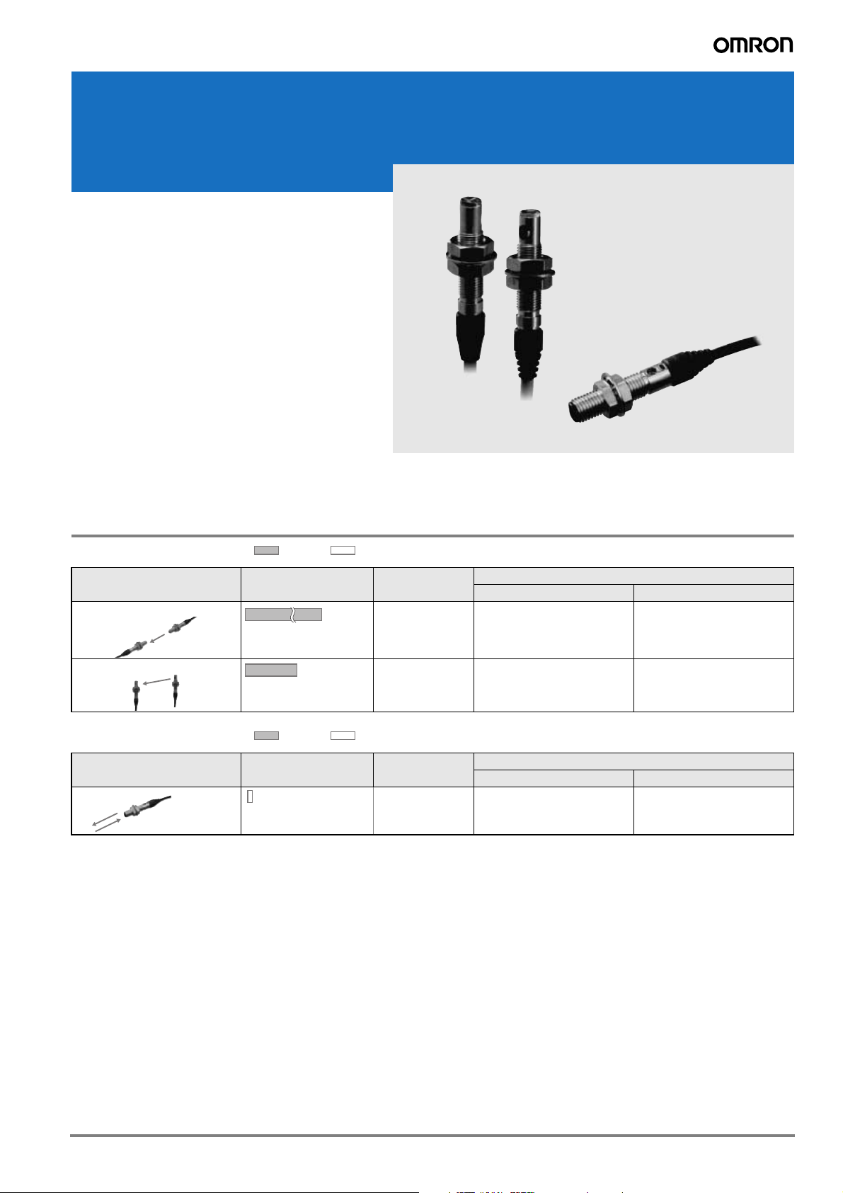
Miniature photoelectric sensors in M5 and M6 sized housing
500 mm
E3T-C
The E3T-C family of miniature
photoelectric sensors is the ideal
solution when mounting space is
crucial.
• axial and radial M5 sized through-beam sensors
• axial M6 sized diffuse-reflective sensors
• pre-wired models in stainless steel housing
Ordering Information
M5 cylindrical housing Red light Infrared light
Sensor type Sensing distance Operation mode
Through-beam (axial) Dark-ON E3T-CT12 2M E3T-CT14 2M
Through-beam (radial) Dark-ON E3T-CT22S 2M E3T-CT24S 2M
M6 cylindrical housing Red light Infrared light
Sensor type Sensing distance Operation mode
3 to 50 mm
1 m
Light-ON E3T-CD11 2M E3T-CD13 2M
NPN output PNP output
NPN output PNP output
Order code
Order code
1E3T-C
Page 2
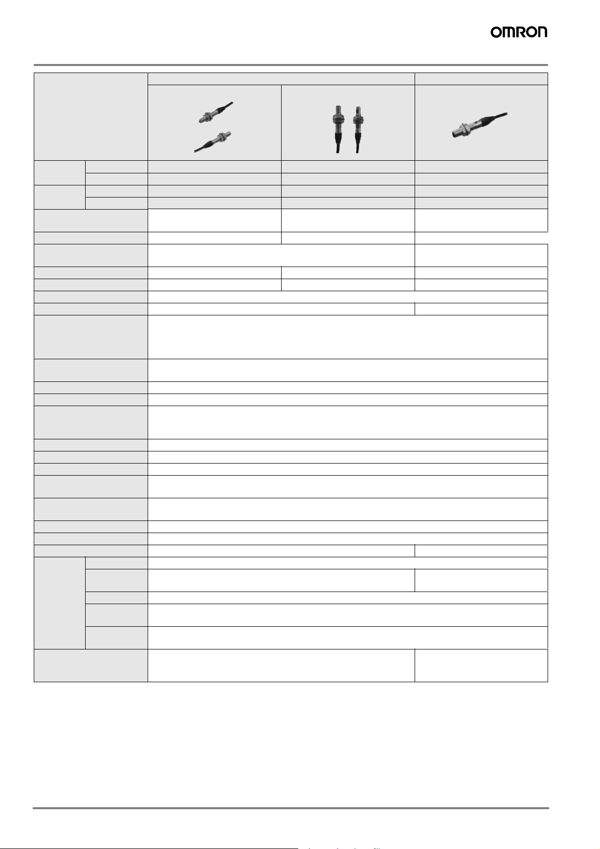
Ratings and Specifications
Through-beam Diffuse-reflective
Cylindrical type (Top-view)
Item
NPN output
PNP output
Sensing distance
Standard sensing object Opaque, 4-mm dia. min. Opaque, 5-mm dia. min. ---
Hysteresis (white paper)
Directional angle Receiver: 2 Receiver: 10 ---
Light source (wavelength) Red LED (630 nm) Red LED (625 nm) Infrared LED (870 nm)
Power supply voltage 12 to 24 VDC 10%, ripple (p-p) 10% max.
Current consumption 30 mA max. (Emitter 15 mA max., Receiver 15 mA max.) 20 mA max.
Control output
Protection circuits
Response time Operate or reset: 0.5 ms max.
Ambient illumination Incandescent lamp: 3,000 lx max.
Ambient temperature range
Ambient humidity range Operating or Storage: 35% to +85% (with no condensation)
Insulation resistance 20 M min. at 500 VDC
Dielectric strength 500 VAC, 50/60 Hz for 1 min.
Vibration resistance
(destruction)
Shock resistance
(destruction)
Degree of protection IP65 (IEC 60529)
Connection method Pre-wired (standard length: 2 m)
Weight (packed state) Approx. 60 g Approx. 40 g
Materials
Accessories
Light-ON --- --- E3T-CD11
Dark-ON E3T-CT12 E3T-CT22S --Light-ON --- --- E3T-CD13
Dark-ON E3T-CT14 E3T-CT24S ---
1 m 500 mm 3 to 50 mm
--- 15% or less of the sensing
Load power supply voltage: 30 VDC max.
Load current: 80 mA max.
(residual voltage: 1 V max.)
Open-collector output
Power supply reverse polarity protection,
Output short-circuit protection
Operating: 25 to +55C
Storage: 30 to +70C
(with no icing or condensation)
10 to 55Hz, 1.5-mm double amplitude for 2 hours each in X, Y, and Z directions
500 m/s2 3 times each in X, Y, and Z directions
Case SUS303
Display
window
Lens Polysulfone
Hexagonal
nuts
Toothed
washers
Polysulfone Epoxy
SUS303
SUS303
Instruction manual, Hexagonal nuts, Toothed washers Instruction manual, Hexagonal
Cylindrical type (Side-view)
Cylindrical type (Top-view)
(100 100 mm white paper)
distance
nuts, Toothed washers, Adjustment driver
2 Miniature Photoelectric Sensors
Page 3
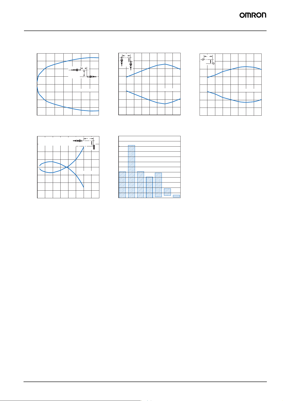
Engineering Data (Typical)
Parallel Operating Range
Through-beam
E3T-CT1@ E3T-CT2@S (Top to Bottom) E3T-CT2@S (Right to Left)
80
60
40
Distance Y (mm)
20
0
0.25 0.5 0.75 1.0 1.25 1.5 1.75
−20
−40
−60
−80
Distance X (m)
X
Y
200
150
100
Distance Y (mm)
−50
−100
−150
−200
50
X
Y
0
0.2 0.4 0.6 0.8 0.7 0.5 0.3 0.1
Distance X (m)
Operating Range Sensing Distance vs. Material
Diffuse-reflective Diffuse-reflective
E3T-CD1@ E3T-CD1@
20
Sensing object:
100 x 100 mm white paper
15
10
Distance Y (mm)
5
0
20 30 10 40 50 60 70 80
−5
−10
−15
−20
X
Y
Distance X (m)
120
110
100
90
80
Sensing distance (mm)
70
60
50
40
30
20
10
0
White
paper
sheet
Glass
Plywood
Stainless
Cardboard
Black
Black
rubber
Material
paper
200
150
100
Distance Y (mm)
−50
−100
−150
−200
50
X
Y
0
0.2 0.4 0.6 0.8 0.7 0.5 0.3 0.1
Distance X (m)
3E3T-C
Page 4

I/O Circuit Diagrams
Light incident
Light interrupted
Operation indicator
(orange)
ON
OFF
Output
transistor
Load
(e.g., relay)
Operate
Reset
ON
OFF
(Between brown (1)
and black (4) leads)
1
3
4
3
1
ZD
0 V
Through-beam Receivers and Reflective Sensors
Operation
indicator
(orange)
Stability
indicator
(green)
Photoelectric
Sensor
Main
Circuit
Brown
Black
Blue
(Control output)
12 to 24 VDC
Load
(relay)
Through-beam Emitters
Brown
Blue
12 to 24 VDC
Photoelectric
Sensor
Main
Circuit
80 mA
max.
1
3
4
1
3
0 V
Z
D
Through-beam Receivers and Reflective Sensors
Through-beam Emitters
Operation
indicator
(orange)
Stability
indicator
(green)
Photoelectric
Sensor
Main
Circuit
Photoelectric
Sensor
Main
Circuit
Brown
Blue
12 to 24 VDC
80 mA
max.
Brown
Black
Blue
12 to 24 VDC
Load
(relay)
(Control output)
NPN Output
Model Operation mode Timing charts Output circuit
E3T-CD11 Light-ON
E3T-CT12
E3T-CT22S
Dark-ON
Light incident
Light interrupted
Operation indicator
(orange)
Output
transistor
Load
(e.g., relay)
Operate
ON
OFF
ON
OFF
Reset
(Between brown (1)
and black (4) leads)
PNP Output
Model Operation mode Timing charts Output circuit
E3T-CD13 Light-ON
E3T-CT14
Dark-ON
E3T-CT24S
Light incident
Light interrupted
ation indicator
Oper
(orange)
Output
transistor
Load
(e.g., relay)
Operation indicator
(orange)
Output
transistor
Load
(e.g., relay)
Operate
Light incident
Light interrupted
Operate
ON
OFF
ON
OFF
Reset
(Between blue (3)
and black (4) leads)
ON
OFF
ON
OFF
Reset
(Between blue (3)
and black (4) leads)
4 Miniature Photoelectric Sensors
Page 5

Safety Precautions
Refer to Warranty and Limitations of Liability.
WARNING
This product is not designed or rated for ensuring
safety of persons. Do not use it for such purpose.
Do not apply AC power to the E3T, otherwise the E3T
may rupture.
Precautions for Correct Use
Do not use the product in atmospheres or environments that exceed
product ratings.
Wiring
The maximum power supply voltage is 26.4 VDC. Before turning the
power ON, make sure that the power supply voltage be not more than
maximum voltage.
Load short-circuit protection
The E3T incorporates a load short-circuit protection function. If the
load short-circuits, the output of the E3T will be turned OFF. Then,
recheck the wiring and turn on the E3T again to reset the load shortcircuit protection function. The load short-circuit protection function
will work if there is a current flow that is 1.5 times larger than the rated
load current. When using a capacitance load, be sure that the inrush
current will not exceed 1.5 times larger than the rated current.
Mounting
When mounting the Sensor, never strike it with a heavy object, such
as a hammer. Doing so may reduce its watertight properties. Use
screws with spring, flat, or toothed washers to secure the Sensor.
Tightening Torque
Small Cylindrical Sensors: 1 N·m max
Adjusting
Indicators
The following graphs indicate the status of each operating level.
Be sure to use the E3T within the stable operating range.
Stability
indicator
(green)
Stable
operation
*
range
Unstable
operation
*
range
Stable
operation
*
range
*
If the E3T fs operating level is set to the stable operation range, the
E3T will be in most reliable operation without being influenced by
temperature change, voltage fluctuation, dust, or setting change. If
the operating level cannot be set to the stable operation range, pay
attention to environmental changes while operating the E3T.
Operating
level x 1.2
Operating
level
Operating
level x 0.8
Light
ON
OFF
ON
Operation indicator (orange)
E3T- @@@1
E3T- @@@3
ON
OFF
E3T- @@@2
E3T- @@@4
OFF
ON
E3T-CD@@ Sensitivity Adjustment
Use the special screwdriver that is provided with the Sensor to adjust
the sensitivity. Do not exceed 0.8 N·m when turning the adjuster.
Others
Do not install the E3T in the following locations.
Locations subject to excessive dust or dirt
Locations subject to direct sunlight
Locations subject to corrosive gas
Locations subject to contact with organic solvents
Locations subject to vibration and shock
Locations subject to contact with water, oil, or chemicals
Locations subject to high humidities that might result in
condensation
Mounting the Sensor on Moving Parts
Consider models that use break
B
resistant cables (e.g., Robotics
Cables) if the Sensor will be
mounted on a moving part, such as a
robot hand. The flexing resistance of
Robotics Cable at approximately
A
C
θ θ
400 thousand times is far superior to
that of standard cable at
approximately 14 thousand times.
R
Cable Bending Rupture Test
(Tough Cable Breaking Test)
The cable is repeatedly bent with
power supplied to check the number
of bends until the current is turned
Weight
OFF.
Specimen Standard cable
Test
Bending angle () 90 each to the left and right
Bending speed 50 times/min
Contents/
Load 200 g
condi-
Operation per bend Once in 1 to 3 in the diagram
tions
Curvature radius of
support point (R)
Result Approx. 14,000 times Approx. 400,000 times
2.4-mm dia.
(7/0.127-mm dia.),
3 conductors
5 mm
Robotics cable
2.4-mm dia.
(20/0.08-mm dia.),
3 conductors
5E3T-C
Page 6

Dimensions
(Unit: mm)
Tolerance class IT16 applies to dimensions in this datasheet unless otherwise specified.
8
26.2
26.2
3.5
M5×0.5
M5×0.5
2.5
9.7
4.4
5.6 dia.
(1.8)
2.5-dia. vinyl-insulated round cable
with 2 conductors (Conductor cross
section: 0.15 mm² (AWG25),
Insulator diameter: 0.8 mm),
Standard length: 2 m
Mounting Hole
10 dia.
5.5
+0.5
−0
Optical
axis
Toothed
washer
Two, hexagonal nuts (M5)
26.2
M5×0.5
Small Cylindrical Sensors
Through-beam Top-view Sensors
E3T-CT1@ (Emitter)
E3T-CT1@ (Receiver)
Emitter: E3T-CT1@-L
Receiver: E3T-CT1@-D
27.2
M5×0.5
6.2
27.2
27.2
3.513.1
2.5 9.7
2.2
8
M5×0.5
M5×0.5
10 dia.
5.6 dia.
5.5
+0.5
−0
Optical
axis
Two, hexagonal nuts (M5)
Toothed
washer
2.5-dia. vinyl-insulated round cable
with 2 conductors (Conductor cross
section: 0.15 mm² (AWG25),
Insulator diameter: 0.8 mm),
Standard length: 2 m
Mounting Hole
Through-beam Side-view Sensors
E3T-CT2@S (Emitter)
E3T-CT2@S (Receiver)
Emitter: E3T-CT2@S-L
Receiver: E3T-CT2@S-D
M6×0.75
29.1
Diffuse-reflective Top-view Sensors
E3T-CD1@
Stability
indicator
10 dia.
8
Two, hexagonal nuts (M5)
Optical
axis
Operation
Indicator
2.7-dia. vinyl-insulated round cable
Toothed
washer
26.2
3.5
(1)
M5×0.5
4.4
2.5
with 3 conductors (Conductor cross
section: 0.15 mm² (AWG25),
Insulator diameter: 0.85 mm),
Standard length: 2 m
5.6 dia.
9.7
Mounting Hole
+0.5
5.5
−0
Operation
indicator
Stability
indicator
10 dia.
8
11 dia.
8
Two, hexagonal nuts (M5)
Optical
axis
Optical
axis
Two, hexagonal nuts (M6)
M6×0.75
(1.2)
2.2
2.8
27.2
13.1 3.56.2
M5×0.5
22.6
19.9
2.5 9.7
2.4 dia.
29.1
Toothed
washer
Sensitivity adjuster
Toothed
washer
6.517
2.7-dia. vinyl-insulated round cable
with 3 conductors (Conductor cross
section: 0.15 mm² (AWG25),
Insulator diameter: 0.85 mm),
Standard length: 2 m
5.6 dia.
Stability
indicator
Operation
indicator
12
6.8 dia.
2.7-dia. vinyl-insulated round cable
with 3 conductors (Conductor cross
section: 0.15 mm² (AWG25),
Insulator diameter: 0.85 mm),
Standard length: 2 m
Mounting Hole
Mounting Hole
+0.5
5.5
−0
+0.5
6.5
−0
6 Miniature Photoelectric Sensors
Page 7

READ AND UNDERSTAND THIS DOCUMENT
Please read and understand this document before using the products. Please consult your OMRON representative if you have any questions or
comments.
WARRANTY
OMRON’s exclusive warranty is that the products are free from defects in materials and workmanship for a period of one year (or other period if
specified) from date of sale by OMRON.
OMRON MAKES NO WARRANTY OR REPRESENTATION, EXPRESS OR IMPLIED, REGARDING NON-INFRINGEMENT,
MERCHANTABILITY, OR FITNESS FOR PARTICULAR PURPOSE OF THE PRODUCTS. ANY BUYER OR USER ACKNOWLEDGES THAT
THE BUYER OR USER ALONE HAS DETERMINED THAT THE PRODUCTS WILL SUITABLY MEET THE REQUIREMENTS OF THEIR
INTENDED USE. OMRON DISCLAIMS ALL OTHER WARRANTIES, EXPRESS OR IMPLIED.
LIMITATIONS OF LIABILITY
OMRON SHALL NOT BE RESPONSIBLE FOR SPECIAL, INDIRECT, OR CONSEQUENTIAL DAMAGES, LOSS OF PROFITS OR
COMMERCIAL LOSS IN ANY WAY CONNECTED WITH THE PRODUCTS, WHETHER SUCH CLAIM IS BASED ON CONTRACT, WARRANTY,
NEGLIGENCE, OR STRICT LIABILITY.
In no event shall responsibility of OMRON for any act exceed the individual price of the product on which liability is asserted.
IN NO EVENT SHALL OMRON BE RESPONSIBLE FOR WARRANTY, REPAIR, OR OTHER CLAIMS REGARDING THE PRODUCTS UNLESS
OMRON’S ANALYSIS CONFIRMS THAT THE PRODUCTS WERE PROPERLY HANDLED, STORED, INSTALLED, AND MAINTAINED AND
NOT SUBJECT TO CONTAMINATION, ABUSE, MISUSE, OR INAPPROPRIATE MODIFICATION OR REPAIR.
SUITABILITY FOR USE
THE PRODUCTS CONTAINED IN THIS DOCUMENT ARE NOT SAFETY RATED. THEY ARE NOT DESIGNED OR RATED FOR ENSURING
SAFETY OF PERSONS, AND SHOULD NOT BE RELIED UPON AS A SAFETY COMPONENT OR PROTECTIVE DEVICE FOR SUCH
PURPOSES. Please refer to separate catalogs for OMRON's safety rated products.
OMRON shall not be responsible for conformity with any standards, codes, or regulations that apply to the combination of products in the
customer’s application or use of the product.
At the customer’s request, OMRON will provide applicable third party certification documents identifying ratings and limitations of use that apply
to the products. This information by itself is not sufficient for a complete determination of the suitability of the products in combination with the end
product, machine, system, or other application or use.
The following are some examples of applications for which particular attention must be given. This is not intended to be an exhaustive list of all
possible uses of the products, nor is it intended to imply that the uses listed may be suitable for the products:
• Outdoor use, uses involving potential chemical contamination or electrical interference, or conditions or uses not described in this document.
• Nuclear energy control systems, combustion systems, railroad systems, aviation systems, medical equipment, amusement machines, vehicles,
safety equipment, and installations subject to separate industry or government regulations.
• Systems, machines, and equipment that could present a risk to life or property.
Please know and observe all prohibitions of use applicable to the products.
NEVER USE THE PRODUCTS FOR AN APPLICATION INVOLVING SERIOUS RISK TO LIFE OR PROPERTY WITHOUT ENSURING THAT
THE SYSTEM AS A WHOLE HAS BEEN DESIGNED TO ADDRESS THE RISKS, AND THAT THE OMRON PRODUCT IS PROPERLY RATED
AND INSTALLED FOR THE INTENDED USE WITHIN THE OVERALL EQUIPMENT OR SYSTEM.
PERFORMANCE DATA
Performance data given in this document is provided as a guide for the user in determining suitability and does not constitute a warranty. It may
represent the result of OMRON’s test conditions, and the users must correlate it to actual application requirements. Actual performance is subject
to the OMRON Warranty and Limitations of Liability.
CHANGE IN SPECIFICATIONS
Product specifications and accessories may be changed at any time based on improvements and other reasons.
It is our practice to change model numbers when published ratings or features are changed, or when significant construction changes are made.
However, some specifications of the product may be changed without any notice. When in doubt, special model numbers may be assigned to fix
or establish key specifications for your application on your request. Please consult with your OMRON representative at any time to confirm actual
specifications of purchased products.
DIMENSIONS AND WEIGHTS
Dimensions and weights are nominal and are not to be used for manufacturing purposes, even when tolerances are shown.
ERRORS AND OMISSIONS
The information in this document has been carefully checked and is believed to be accurate; however, no responsibility is assumed for clerical,
typographical, or proofreading errors, or omissions.
PROGRAMMABLE PRODUCTS
OMRON shall not be responsible for the user’s programming of a programmable product, or any consequence thereof.
COPYRIGHT AND COPY PERMISSION
This document shall not be copied for sales or promotions without permission.
This document is protected by copyright and is intended solely for use in conjunction with the product. Please notify us before copying or
reproducing this document in any manner, for any other purpose. If copying or transmitting this document to another, please copy or transmit it in
its entirety.
7E3T-C
Page 8

In the interest of product improvement, specifications are subject to change without notice.Cat. No. E70E-EN-01
OMRON EUROPE B.V.
Wegalaan 67-69,
NL-2132 JD, Hoofddorp,
The Netherlands
Phone: +31 23 568 13 00
Fax: +31 23 568 13 88
www.industrial.omron.eu
8 Miniature Photoelectric Sensors
 Loading...