

Page 1
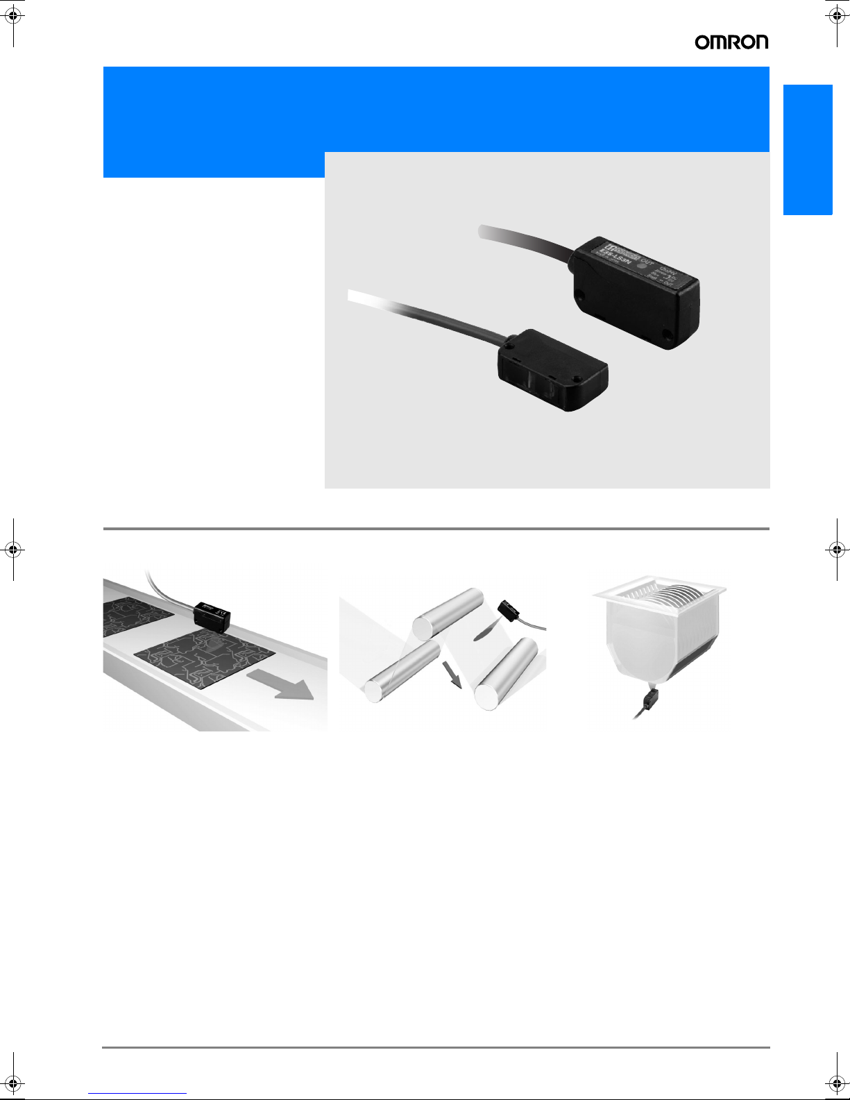
Printed Circuit Board Sensor
E3S-LS3
Printed circuit board
sensor capable of stable detection without
being affected by
holes or notches.
• Suitable for incorporation in devices
(E3S-LS3@).
• Wide range is suitable for component
boards with high or irregularly shaped
components (E3S-LS3@W).
E3S-LS3
Applications
Detecting for PCBs Transparent Film Sheet
Detection
Detection for Wafercassette Mounting
A-145E3S-LS3
Page 2
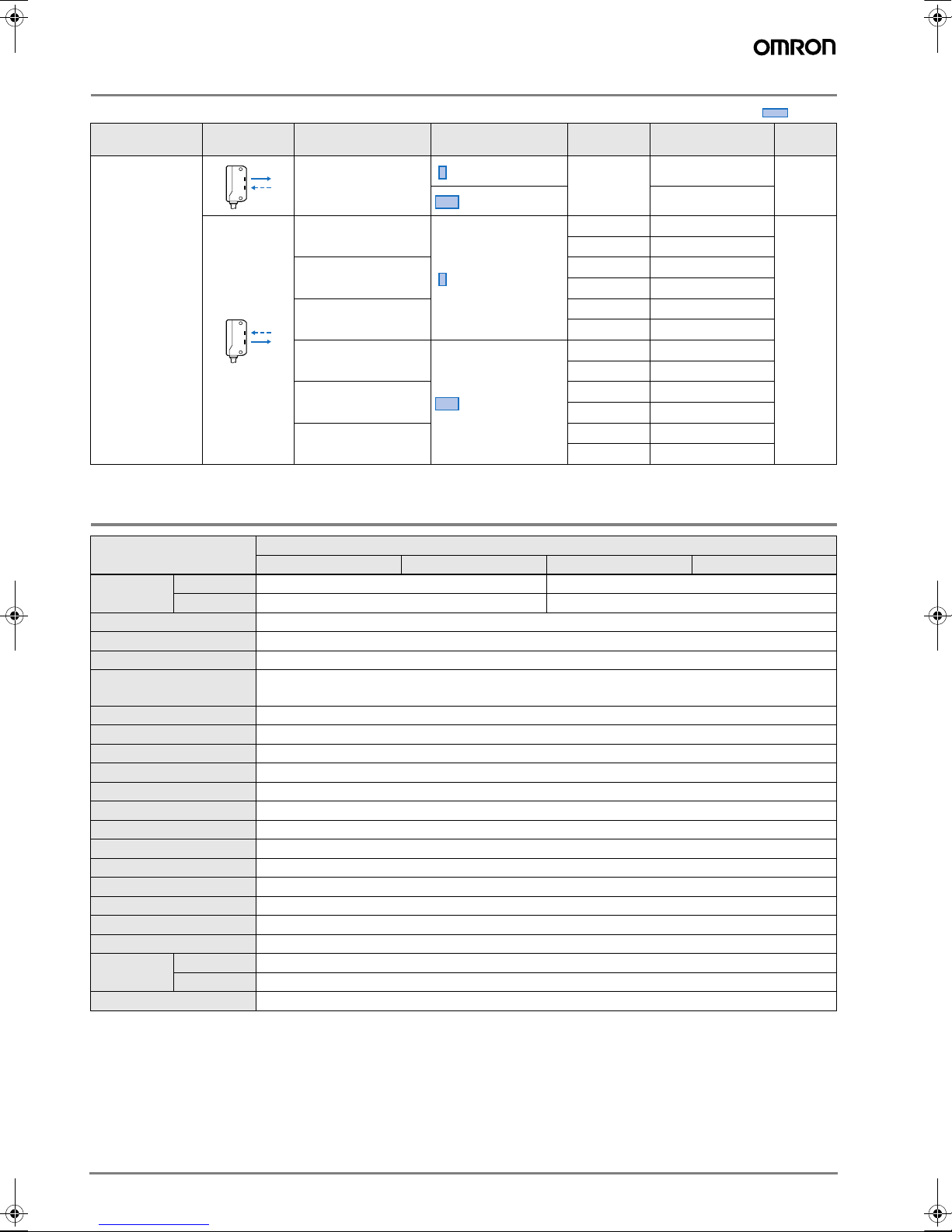
Ordering Information
t
Sensor type Shape Connection method Detection distance *
20 to 35 mm
10 to 60 mm
20 to 35 mm
10 to 60 mm
Limited reflective
* Using 80 x 80 mm white art paper
Pre-wired (2 m) Without
Pre-wired (2 m)
Pre-wired M8
3-pin connector (0.3 m)
Pre-wired M8
4-pin connector (0.3 m)
Pre-wired (2 m)
Pre-wired M8
3-pin connector (0.3 m)
Pre-wired M8
4-pin connector (0.3 m)
Rating/performance
Timer
function
Without E3S-LS3P
With E3S-LS3PT
Without E3S-LS3P-M5J
With E3S-LS3PT-M5J
Without E3S-LS3P-M3J
With E3S-LS3PT-M3J
Without E3S-LS3PW
With E3S-LS3PWT
Without E3S-LS3PW-M5J
With E3S-LS3PWT-M5J
Without E3S-LS3PW-M3J
With E3S-LS3PWT-M3J
Model Output
E3S-LS3N
E3S-LS3NW
Red ligh
NPN
Light ON
PNP
Light ON
Sensor type Limited reflective
Item Model E3S-LS3@ E3S-LS3PT E3S-LS3@W E3S-LS3PWT
Sensing
Light source (wave length) Red LED (660 nm)
Power supply voltage 12 to 24 VDC±10%, ripple (p-p) 10% max.
Current consumption 25 mA max.
Control output
Response time 1 ms max. for operation and reset respectively
Timer function Available with E3S-LS3P(W)T models only. Time range: 0.1 to 1.0 s (adjustable)
Ambient illuminance Receiver side: Incandescent lamp: 5,000 lux max.
Ambient temperature Operating: −10 to 55° C (with no icing or condensation)
Ambient humidity Operating:35% to 85% (with no condensation)
Insulation resistance 20 MΩ min. (at 500 VDC) between charged parts and the case
Dielectric strength 1,000 VAC at 50/60 Hz for 1 minute between charged parts and the case
Vibration resistance 10 to 55 Hz with a 1.5-mm double amplitude for 2 hrs each in X, Y and Z directions
Shock resistance 500 m/s2, 3 times each in X, Y and Z directions
Protective structure IEC60529 IP40
Connection method Pre-wired (standard length: 2 m)/Pre-wired M8 connector (standard length: 0.3 m)
Indicators Operation indicator (orange)
Weight (Packed state) Pre-wired models: Approx. 80 g; Pre-wired M8 connector: Approx. 45 g
Material
Accessories Instruction sheet, M3 screws,
White art paper
Black paper *
Case ABS
Lens Acrylic
20 to 35 mm 10 to 60 mm
20 to 30 mm 15 to 50 mm
Load power supply voltage: 24 VDC max.; Load current: 100 mA max.,
Residual voltage: 2 V max.; Operating mode: Light ON
A-146 Standard Photoelectric Sensors
Page 3

Characteristic data (typical)
Sensing Distance vs. Materials
Sensing distance (mm)
80
70
60
50
40
30
20
10
0
White
Black
paper
paper
E3S-LS3P (T)
E3S-LS3@W (T)
SUS PCB with
green resist
Black
PCB
Material
Output Circuit Diagram
Operating Range (Left and Right)
15
12
9
6
3
0
−3
Distance Y (mm)
−6
−9
−12
−15
Output vs. Set Distance
100
10
Incident light output gain
Operating
1
level
0.1
Sensing object: White paper, 100 x 100 mm
Y
X
0 10203040506070
E3S-LS3PW (T)
E3S-LS3P (T)
Distance X (mm)
E3S-LS3P (T)
E3S-LS3PW (T)
0 5 10 15 20 25 30 35 40 45 50 55 60 65 70 75 80
Distance (mm)
Operating Range (Up and Down)
−15
−12
−9
−6
−3
0
3
Distance Y (mm)
6
9
12
15
Spot Diameter vs. Sensing Distance
35
30
25
20
15
Spot diameter (mm)
10
5
0
Sensing object: White paper, 100 x 100 mm
Y
X
E3S-LS3PW (T)
E3S-LS3P (T)
0 10203040506070
Distance X (mm)
Direction L
L
Direction d
10 20 30 40 50 60 70
Distance (mm)
E3S-LS3
d
NPN output (PNP output will be available soon)
Model
E3S-LSN3
E3S-LS3NW
E3S-LS3P
E3S-LS3PW
E3S-LS3PT
E3S-LS3PWT
Operating
status of output
transistor
Light ON
Operation indicator
(orange)
Output
transistor
Incident light
No Incident light
Operation indicator
(orange)
Output
transistor
Incident light
No Incident light
Operation indicator
(orange)
Output
transistor
T: Off-delay timer (0.1 to 1.0 s)
Timing chart Output circuit
Incident
Interrupted
OFF
OFF
OFF
OFF
OFF
OFF
ON
ON
ON
ON
ON
T
ON
Operation
indicator
(orange)
Main
circuit
12 to 24 VDC
Brown
Load
Black
OUT
Z
Blue
0V
A-147E3S-LS3
Page 4

Dimensions (Unit: mm)
0
0
8
3
8.5
.
0.3
5.4
3
34
3
8
s
e
(
g
m
Timer Adjuster (see note)
Operation Indicator
eceiver
er
8
8
.
s
)
ber
s
3
0 V
t
n
0 V
t
5J
3
)
300
8
300
3
Note: All units are in millimeters unless otherwise indicated.
E3S-LS3N
E3S-LS3NW
E3S-LS3@(T)(-M5J/-M3J)
E3S-LS3@W(T)(-M5J/-M3J)
1
19.
10
19
5.3
Two, M3
mounting holes
Receiver
dia
11.
Operation indicator (orange)
16.5
34
28 28
3
"Vinyl-insulated round cable of 4 dia.
3 cores conductor cross-sectional area:
2
0.12mm
; insulation diameter: 1.2 mmStandard length: 2 m"
12.3
Emitter
Pre-wired M8 3-pin connector (-M5J
Pre-wired M8 4-pin connector (-M3J
Mounting Holes
Two, 3 dia.
M
M
2
1
R
Two, M3 Mounting Hole
Emitt
4-dia., 3-conductor, vinyl-insulated round cabl
conductor cross-sectional area: 0.2 mm, insulation diameter: 1.1 mm),
standard cable len
th: 2
Note:The Timer Adjuster is only for the E3S-LS3PT and E3S-LS3PWT.
Terminal num
Specification
-M
Outpu
Mounting Hole
Two, 3.6 dia
2
-M3J
Ope
Outpu
ALL DIMENSIONS SHOWN ARE IN MILLIMETERS.
To convert millimeters into inches, multiply by 0.03937. To convert grams into ounces, multiply by 0.03527.
Cat. No. E223-E2-01-X
In the interest of product improvement, specifications are subject to change without notice.
A-148 Standard Photoelectric Sensors
 Loading...