

Page 1
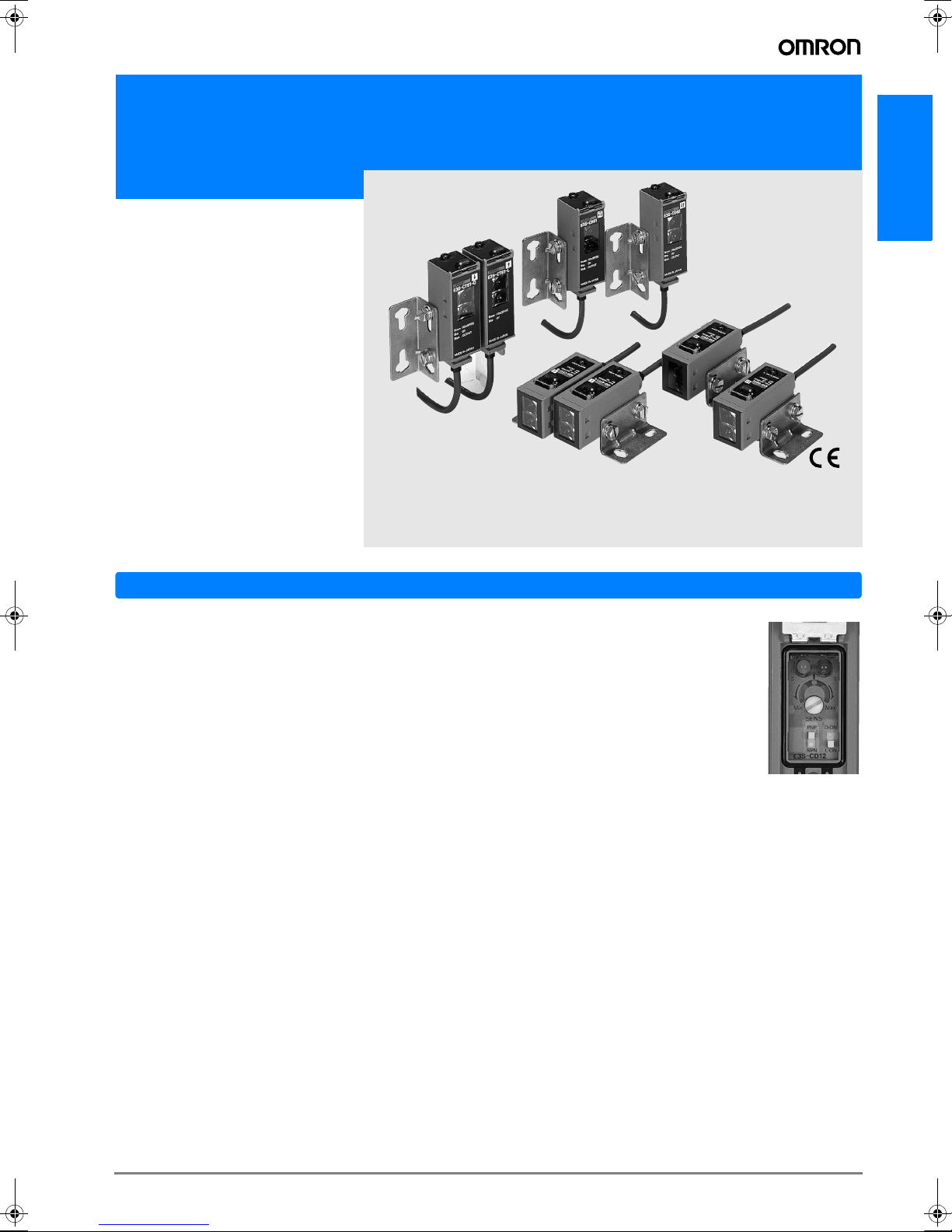
Oil-resistive, compact photoelectric sensor in metal housing
E3S-C
E3S-C
Features
Meets IP67/IP67G (oil tight) and NEMA 6P
standards water/oil resistance
E3S-C meets the IP67 requirements of the IEC standards and
6P of the NEMA standards. E3S-C can be used worry-free in
automotive assembly lines and other production lines where
oil vapor exists. It can also be applied to food processing lines
because it resists hydrogen peroxide, detergent and potassium hydroxide.
High shock resistance of 1,000 m/s
The industry's top-class photoelectric sensor features shock resistance of 1,000 m/s
sor at rated values, and vibration resistance of as high as 10 to
2,000 Hz.
2
, which is as high as that of a proximity sen-
2
Lineup of M12 metal connector joint type models
Lineup of water/oil/shock-resistant M12 metal connector joint
type models are available. This series ensures ease of sensor
replacement during maintenance.
NPN/PNP output selector
The operation panel has the NPN/PNP output selector. You need not prepare two
NPN and PNP models for export. You need
not worry about malfunctions due to noise,
either.
Mutual interference prevention enhanced
(Retroreflective, diffuse reflective models)
Fuzzy inference is introduced into the mutual interference prevention for the first time in the industry. This prevents a malfunction due to mutual interference, enabling two sensors to
be mounted closely side by side.
Easy optical axis alignment
OMRON's original "automatic position compensation system"
minimizes misalignment of mechanical and optical axes to
merely ±2°. The optical axis is aligned perfectly by only installing the sensor.
A-101E3S-C
Page 2
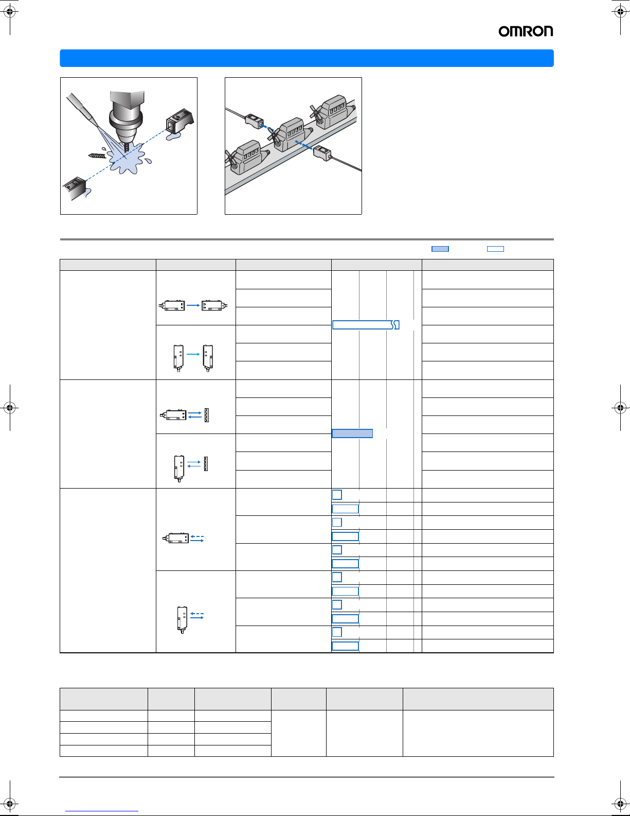
Application
Drill breakage detection
Detection of engine block
IP67 ensures a worry-free use in oil
mist environment.
Ordering Information
Sensors
Sensor type Shape Connection method Sensing distance Model
Horizontal Model
Through-beam
Vertical Model
Pre-wired E3S-CT11
Junction connector E3S-CT11-M1J
Plug-in connector E3S-CT16
30m
Pre-wired E3S-CT61
Junction connector E3S-CT61-M1J
Plug-in connector E3S-CT66
Red light Infrared light
Horizontal Model
Retroreflective Models
Vertical Model
Horizontal Model
Diffuse-reflective
Vertical Model
Accessories (Order Separately)
Slits
Slit width
Width 0.5 mmx11 mm
Width 1 mmx11 mm
Width 2 mmx11 mm
Width 4 mmx11 mm
Sensing
distance
1.8 m
3.5 m
7 m
15 m
Pre-wired E3S-CR11
Junction connector E3S-CR11-M1J
Plug-in connector E3S-CR16
Pre-wired E3S-CR61
Junction connector E3S-CR61-M1J
Plug-in connector E3S-CR66
Pre-wired
Junction connector
Plug-in connector
Pre-wired
Junction connector
Plug-in connector
Minimum sensing
object (typical)
0.5 mm dia.
1 mm dia.
2 mm dia.
2.6 mm dia.
3m
700mm
2m
700mm
2m
700mm
2m
700mm
2m
700mm
2m
700mm
2m
Model Quantity Remarks
E39-S61
1 each for emitter
and receiver
(total of 8 pcs.)
(Plug-in type long slit) Can be used
with through-beam E3S-CT#1
(-M1J).
E3S-CD11
E3S-CD12
E3S-CD11-M1J
E3S-CD12-M1J
E3S-CD16
E3S-CD17
E3S-CD61
E3S-CD62
E3S-CD61-M1J
E3S-CD62-M1J
E3S-CD66
E3S-CD67
A-102 Standard Photoelectric Sensors
Page 3
Reflectors
Name Sensing distance (typical) Model Quantity Remarks
Reflectors
3 m (rated value) E39-R1 1 Attached to the Retroreflective E3S-CR#1 (-M1J).
4 m E39-R2 1 ---
Small reflector
1.5 m E39-R3 1 ---
750 mm E39-R4 1 ---
700 mm (50 mm) * E39-RS1 1 pc.
Tape Reflector
The M.S.R. function is available.1,100 mm (100 mm) * E39-RS2 1 pc.
1,400 mm (100 mm) * E39-RS3 1 pc.
* Values in parentheses indicate the minimum required distance between the sensor and reflector.
Note: 1 .When the reflector used is other than the supplied one, set the sensing distance to about 0.7 times of the typical example as a guideline.
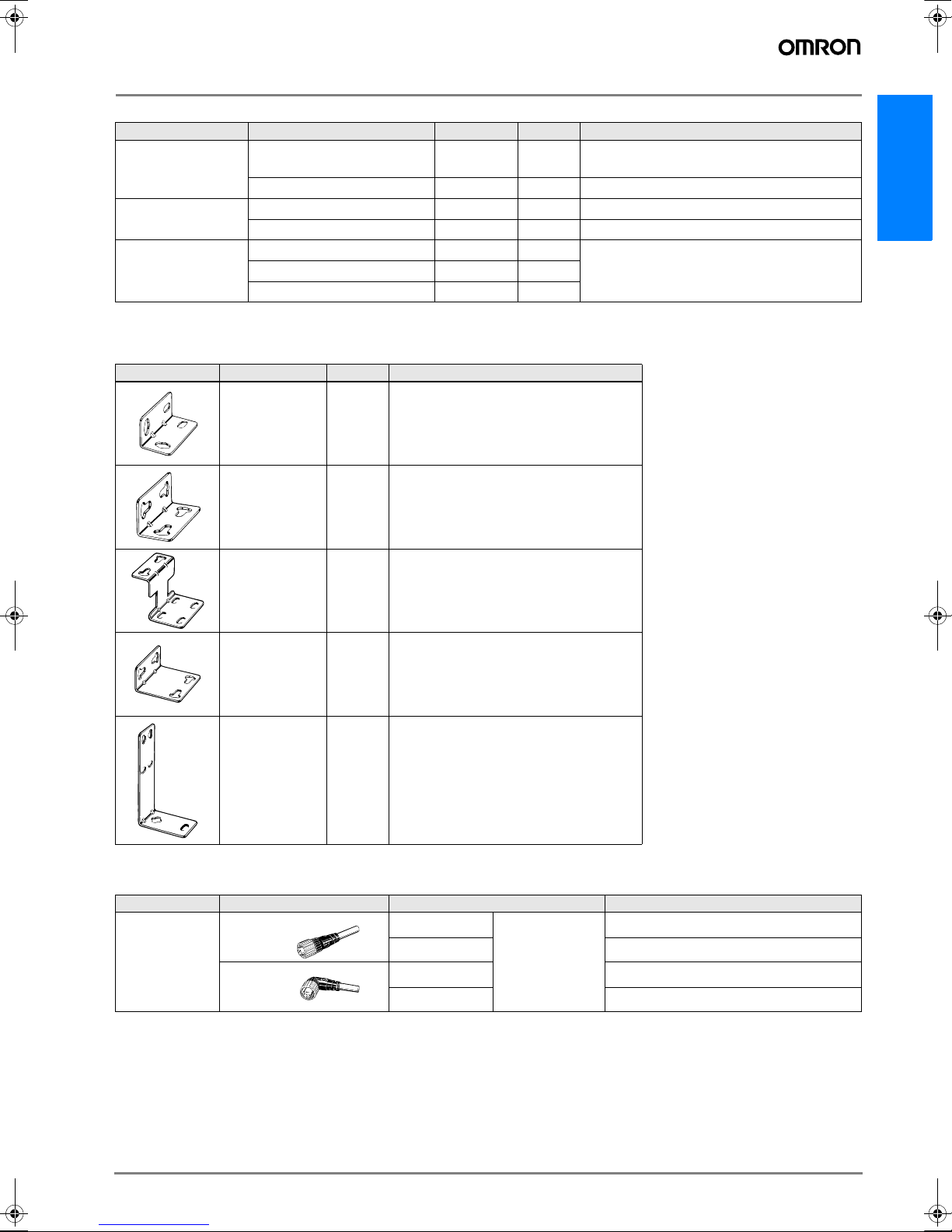
Mounting Brackets
Shape Model Quantity Remarks
E39-L102 1 Attached to the horizontal model.
E39-L103 1 Attached to the vertical model.
Mounting bracket designed to switch from
E39-L85 1
E3S-#####42, 44 to the vertical model of
E3S-C.
E3S-C
E39-L86 1
E3S-#####43 to the vertical model of E3SC.
E39-L87 1 ---
Mounting bracket designed to switch from
Note: If a through-beam model is used, order two Mounting Brackets for the emitter and receiver respectively.
Sensor I/O Connectors
Cable Shape Cable length Model
Straight
Standard cable
L-shaped
2 m
5 m
2 m
3-wire type
5 m
XS2F-D421-DC0-A
XS2F-D421-GC0-A
XS2F-D422-DC0-A
XS2F-D422-GC0-A
A-103E3S-C
Page 4

Rating/performance
Sensor type Through-beam
Item
Sensing distance
Standard sensing
object
Differential distance --- 20% max. of sensing distance
Directional angle
Light source
(wave length)
Supply
voltage
Current
consumption
Control output
Protective circuits
Response time Operation or reset: 1 ms max.
Sensitivity
adjustment
Ambient illuminance (on Receiver lens) Incandescent lamp: 5,000 lux max. Sunlight: 10,000 lux max.
Ambient
temperature
Ambient humidity Operating: 35% to 85%RH, Storage: 35% to 95%RH (with no condensation)
Insulation
resistance
Dielectric strength 1,000 VAC at 50/60 Hz 1 minute
Vibration resistance 10 to 2,000 Hz double amplitude 1.5 mm or 300 m/s2 for 0.5 h in each of X, Y, Z directions
Shock resistance 1000 m/s2 (approx.- l00G) 3 times each in X, Y, and Z directions
Protective structure IEC Standard IP67, NEMA 6P (limited to indoors use) *
Connection method Pre-wired (standard length: 2 m), Junction connector (standard length: 300 mm)
Weight
(Packed state)
Material
Accessories Mounting bracket (with screws), adjusting screwdriver, instruction manual, reflector (Retroreflective model only)
* NEMA (National Electrical Manufacturers Association) Standards
Model
Case Zinc diecast
Operation
panel cover
Lens Acrylics
Mounting
Brackets
Horizontal E3S-CT11 (-M1J) Horizontal E3S-CR11 (-M1J) Horizontal E3S-CD11 (-M1J) Horizontal E3S-CD12 (-M1J)
Vertical E3S-CT61 (-M1J) Vertical E3S-CR61 (-M1J) Vertical E3S-CD61 (-M1J) Vertical E3S-CD62 (-M1J)
30 m
Opaque, 15dia. min. Opaque: 75 mm dia. min. ---
Both emitter and receiver:
3° to 15°
Infrared LED (880 nm) Red LED (700 nm) Infrared LED (880 nm)
10 to 30 VDC [ripple (p-p) 10% included]
Both emitter and receiver:
25 mA max.
Load supply voltage 30 VDC max., load current 100 mA max. (residual voltage NPN output: 1.2 V max., PNP output: 2.0 V max.) Open collector output type (NPN/PNP switch selectable) Light-ON/Dark-ON switch selectable
Reverse polarity protection,
output short-circuit protection
Single-turn adjustment 2-turn endless adjuster (with indicator)
Operating: -25°C to 55°C, Storage: -40°C to 70°C (with no icing or condensation)
20 M min. at 500 VDC
About 270 g (pre-wired
type) About 230 g (M12
connector joint type)
Polyethyl sulfon
Stainless steel (SUS304)
Retroreflective model
(with M.S.R. function)
3 m (When using the
E39-R1)
3° to 10°
40 mA max.
Reverse polarity protection, output short-circuit protection, mutual interference prevention
About 160 g (pre-wired
type) About 130 g (M12
connector joint type)
700 mm (White paper 300 x
300 mm)
About 150 g (pre-wired type) About 110 g (M12 connector joint type)
Diffuse-reflective
2 m (White paper 300 x
300 mm)
---
Operation/reset: 2 ms
max. each
A-104 Standard Photoelectric Sensors
Page 5

Output Circuit Diagram
NPN output
Model
E3S-CT11(-M1J)
E3S-CT61(-M1J)
E3S-CR11(-M1J)
E3S-CR61(-M1J)
E3S-CD11(-M1J)
E3S-CD12(-M1J)
E3S-CD61(-M1J)
E3S-CD62(-M1J)
Operating status of
output transistor
Light ON
Dark ON
Emitter (Through-beam Models)
Light
indicator
(red)
Output
transistor
Load
(Relay)
Light
indicator
(red)
Output
transistor
Load
(Relay)
Timing chart
Incident
Interrupted
ON
OFF
ON
OFF
Operate
Reset
(Between brown and black)
Incident
Interrupted
ON
OFF
ON
OFF
Operate
Reset
(Between brown and black)
Emitter
indicator
(red)
Main
circuit
1
3
Brown
Blue
Mode selection switch
LON
(LIGHT ON)
DON
(DARK ON)
Output circuit
Receiver (Through-beam Models)
Retroreflective, Diffuse Reflective, and Limited Reflective Models
Light
indicator
Stability
indicator
(red) (green)
Main
circuit
* Note: Set the NPN and PNP output selector to NPN.
PNP
output transistor
NPN and PNP
output selector
NPN
output transistor
ZD
*
ZD
1
4
3
Brown
Black
Blue
10 to 30 VDC
Load
Load current
Control output
Connector Pin Arrangement
1
2
4
3
Note: Terminal 2 is not used.
Connector Pin Arrangement
10 to 30 VDC
1
2
4
3
Note: Terminal 2 and 4 are not used.
E3S-C
0V
PNP output
Model
E3S-CT11(-M1J)
E3S-CT61(-M1J)
E3S-CR11(-M1J)
E3S-CR61(-M1J)
E3S-CD11(-M1J)
E3S-CD12(-M1J)
E3S-CD61(-M1J)
E3S-CD62(-M1J)
Operating status of
output transistor
Light
indicator
Light ON
Dark ON
(red)
Output
transistor
Load
(Relay)
Light
indicator
(red)
Output
transistor
Load
(Relay)
Emitter (Through-beam Models)
Connectors (Sensor I/O connectors)
Pin No.
2
13
4
1
2
3
4
XS2F-D421-DC0-A
Timing chart
Incident
Interrupted
ON
OFF
ON
OFF
Operate
Reset
(Between blue and black)
Incident
Interrupted
ON
OFF
ON
OFF
Operate
Reset
(Between blue and black)
Emitter
indicator
(red)
Main
circuit
Mode selection switch
LON
(LIGHT ON)
DON
(DARK ON)
Brown
1
Blue
3
Wire, outer
Classifi-
Brown
Blue
Black
Class
For DC
Wire colors
cation
jacket color
Brown A +V
DC
Blue C 0V
Black D Output
Note: Terminal 2 is not used.
Note: Pin 2 is open.
Output circuit
Receiver (Through-beam Models)
Retroreflective, Diffuse Reflective, and Limited Reflective Models
Light
indicator
Stability
indicator
(red)
(green)
Main
circuit
* Note: Set the NPN and PNP output selector to PNP.
PNP
output transistor
NPN and PNP
output selector
NPN
output transistor
ZD
ZD
Connector Pin Arrangement
1
2
4
3
Note: Terminal 2 is not used.
Connector Pin Arrangement
10 to 30 VDC
1
2
4
3
Note: Terminal 2 and 4 are not used.
Connector
Connector
pin No.
pin No.
Brown
--
--- B ---
Blue
(1)
(2)
(3)
Black (4)
Use
Application
+V
--
0V
Output
10 to 30 VDC
Brown
1
Black
4
*
3
Blue
Load current
Load
Control output
0V
A-105E3S-C
Page 6

Characteristic data (typical)
Operating Range
Through-beam Retroreflective Models Diffuse-reflective
E3S-CT#1(-M1J)
500
300
100
50
Excess gain ratio
30
E3S-CR#1 (-M1J) + E39-R1 (supplied reflector)
500
Reflector: E39-R1
300
100
50
Excess gain ratio
30
E3S-CD##(-M1J)
500
Sensing object: White paper
300
E3S-CD#1
100
50
Excess gain ratio
30
E3S-CD#2
10
5
3
Operation
1
level
0 10203040
Distance (m)
10
5
3
Operation
1
level
01234
Distance (m)
10
5
3
Operation
1
level
0123
Nomenclature:
(Horizontal type) (Vertical type)
Control unit cover
Control unit cover
Stability
Stability
indicator (green)
indicator (green)
NPN and PNP
NPN and PNP
output selector * 1
output selector * 1
SL
SL
Min Max
Min Max
SENS
SENS
D·ON
PNP
D·ON
PNP
NPN L·ON
NPN L·ON
E3S-CD12
E3S-CD12
Light indicator (red)
Light indicator (red)
Sensitivity adjuster
Sensitivity adjuster
L-ON and D-ON
L-ON and D-ON
selector * 2
selector * 2
Model
Model
Stability indicator
*1. The output transistor can be selected with the NPN/PNP output selector.
*2. The operation mode can be selected with the L/OND/ON selector.
Note: The through-beam and retroreflective models are different in sensitivity
(green)
NPN and PNP
output selector * 1
L-ON and
D-ON selector * 2
adjuster shape.
SL
PNP
NPN
SENS
D
ON
L
ON
MaxMin
Operation
Sensitivity adjustment (diffuse reflective model, light-ON)
Sequence Detection state Sensitivity adjuster Indicator state Adjustment procedure
Distance (m)
Control unit cover
Light indicator
(red)
Sensitivity adjuster
Sensing object
Background
Sensing object
(A)
Min Max
Min Max
A Point A
B Point B
Photoelectric
Sensor
Photoelectric Sensor
C Setting ---
Min Max
Unlike the conventional models, the E3S-C scarcely has sensitivity variations between products. Therefore, you need to make the
above adjustment on only one diffuse reflective model of E3S-CD that will be used for detection under the same conditions, and
match the indicator points of the other diffuse reflective models of E3S-CD with the above adjusted one. (You need not match the
sensitivity of each sensor.)
A-106 Standard Photoelectric Sensors
ONÆOFF OFFÆON
Place a sensing object in the predetermined position, turn the
sensitivity adjuster clockwise (increase sensitivity) until the
incident indicator (red) is turned ON, and define this position
Stability indicator
(green)
Light indicator
(red)
as (A).
Remove the sensing object, turn the sensitivity adjuster fur-
(C)
(B)
ONÆOFF ONÆOFF
Stability indicator
(green)
Light indicator
ther clockwise until the incident indicator (red) is turned ON
by a background object, and define this position as (B). Turn
the sensitivity adjuster counterclockwise (decrease sensitivity) from (B) until the incident indicator (red) is turned OFF,
(red)
and define this position as (C). When there is no background
object, define the maximum adjuster position (Max) as (C).
(C)(A)
ON ON´OFF
Set the adjuster in the middle of positions (A) and (C) (optimum sensitivity setting). Also make sure that the stability indicator (green) is turned ON when there is an object and
Stability indicator
(green)
Light indicator
when there is no object.
When the indicator is not turned ON, recheck the detection
(red)
method since there is a little allowance.
Page 7

Precautions
Correct Use
Design
Fuzzy mutual interference prevention
When reflective photoelectric sensors are installed side by
side, one sensor may receive the light from the other sensor,
which may disturb the incident signal, causing a malfunction.
The fuzzy mutual interference prevention monitors interfering
light for a predetermined period of time before light is emitted,
and imports the interfering light level and incident frequencies
as data. Using these values, fuzzy inference is made to find
the risk of malfunction to control the light emitting timing, reducing the risk.
(When risk is low)
Light is emitted after interfering light is gone.
(Direct installation)
Install the E3S-C as shown below.
[M4 screwing]
M4
[M3 screwing]
Two, 4.5 dia.
through holes
M4 hole
M4 hole
2-M3
E3S-C
Light
interference
Emission
pattern
(When risk is high)
Light is emitted after shifting to a gap of interfering light.
Light
interference
Emission
pattern
Wiring Considerations
Cable
• An oil-resistance cable is used to ensure oil resistance.
• The bending radius should be 25 mm or more.
Installation
Sensor installation
• Note that during the E35-C installation, hammering it will
damage the water resistance function.
• Use an M4 screw, tightened to a torque of no more than
1.18 Nm.
(When using the mounting bracket)
• To set the sensor on the mechanical axis, use the optical
axis locking holes.
• When the sensor cannot be set on the mechanical axis,
move the E3S-C vertically and/or horizontally and set it in
the center of the area where the incident indicator is turned
ON. Make sure that the stability indicator is ON.
M4 hole
M4 hole
M3
Optical axis adjustment
(Optical axis locking holes)
By fitting screws into the optical axis locking holes, the mounting bracket is set onto the mounting shaft of the mounting
bracket.
For adjustment
Optical
axis
Mounting axis
Four M4 optical axis lock holes
A-107E3S-C
Page 8

Optical axis position of through-beam model
Unlike the conventional product, the through-beam model has
two lenses, but the one actually used is as shown below.
When fitting the slit, use it after matching the slit hole with the
used lens.
(Horizontal model) (Vertical model)
Lens in use.
The slit must be on this side.
Lens not in use.
Lens in use.
Lens not in use.
Water Resistance
To ensure water resistance, tighten the operation panel cover
screws to 0.34 Nm to 0.54 Nm torque.
Miscellaneous
Oil resistance/chemical resistance
• Though E3S-C has a high oil resistance, it may not be able
to exhibit its performance depending on the oil type. Use oil
in compliance with the following table.
• Regarding the oil resistance of E3S-C, it has passed tests
on the oils given in the following table. Refer to the table for
examining the oil to be used.
Testing
oil classi-
fication
JIS classi-
fication
Product name
Lubricant --- Velocity No. 3 2.02
Water-insoluble
coolant
Class 2
Class 2
No. 11
Class W1
Watersoluble
coolant
Class W1
Class W2
Note: 1 . The E3S-C was immersed in the oils in the above table at 50°C for 240
hours, and passed the test of 100-M or more insulation resistance.
2 . For use in the environment where the E3S-C is exposed to the oil other
than those in the above table, use the dynamic viscosity and PH in the
above table. Pre-examine the oils since the sensor may be affected by
additives and like in the oils.
Daphne Cut
No. 5
Yushiron Oil No. 2ac Less than 10
Yushiroken EC50T-3
No. 1
Yushiron Lubic HWC68
Gryton 1700D
No. 2
Yushiroken S50N
No. 1
Dynamic vis-
2
at 40°C
50
/s)
cosity (mm
Not less than
10 to less than
---
PH
---
7 to 9.5
7 to 9.9
7 to 9.2
7 to 9.8
Dimensions (Unit: mm)
Sensors
Through-beam model (horizontal model)
E3S-CT11(-M1J)
With mounting bracket
18.5
22.2
Emitter: E3S-CT##-L
Receiver: E3S-CT##-D
Lens (17 x 11) Optical axis
23
(A)*
1
2-M4
* Note: 1. Mounting bracket can be attached to side A.
2. The emitter for through-beam sensors have only the power supply indicator.
3. The cable for emitters for through-beam sensors is two-conductor, 4 dia. (27 x 12 dia.).
9.3
1.5
Stability
indicator
(green)
9.2
2.2
4
18
50
Light indicator (red)
4.2
6.2
38.2
25.420.8
Vinyl-insulated round cable with
three conductors, 4 dia.
(18 x 0.12 dia.); standard length: 0.3 m
Vinyl-insulated round cable with
M3 x 5
* 2
8.3
three conductors, 4 dia.
(18 x 0.12 dia.); standard length: 2 m * 3
20
20.4
20
4.2
Stainless steel
(SUS304)
29.5
17.3
Junction connector models (-M1J)
M12 x 1
16 dia.
Mounting holes
2-M4
25.4
A-108 Standard Photoelectric Sensors
Page 9

Through-beam model (vertical model)
E3S-CT61(-M1J)
With mounting bracket
Vinyl-insulated round cable with three
conductors, 4 dia. (18
standard length: 0.3 m
¥0.12 dia.);
Junction connector models (-M1J)
M12
¥1
16 dia.
E3S-C
Optical
axis
22.2
Lens (17
Stability indicator (green)
7.2
Light indicator (red) * 2
5.8
23
(A) * 1
M3
¥5
* 1. Mounting bracket can be attached to side A.
* 2. The emitter for through-beam sensors have only the power supply indicator.
* 3. The cable for emitters for through-beam sensors is two-conductor, 4 dia. (27
20.2
2-M4
Retro/diffuse reflective model (horizontal model)
E3S-CR11(-M1J)
E3S-CD11(-M1J)
E3S-CD12(-M1J)
Optical axis
15.8 7.4
¥11)
2.2
23.2
57
4.2
12.9
With mounting bracket
31
43.8
¥12 dia.).
Vinyl-insulated round cable
with three conductors, 4 dia. (18
standard length: 2 m * 3
4.2 9.2
4.2
25.4
Stainless steel
12.9
(SUS304)
1.5
Vinyl-insulated round cable
with three conductors, 4 dia.
(18 x 0.12 dia.); standard length: 0.3 m
¥0.12 dia.);
20.4
20
Mounting holes
20
32.2
12
2-M4
25.4
Junction connector models (-M1J)
M12 x 1
16 dia.
Lens (17 x 11) Receiver
23
9
(A)*1
Optical
Emitter
axis
* Note: Mounting bracket can be attached to side A.
1
2-M4
50
6.2
Light indicator
(red)
4.2
38.2
25.420.8
18.5
22.2
Stability
indicator
(green)
9.2
2.2
4
18
9.3
1.5
M3 x 5
4.2
8.3
Stainless steel (SUS304)
Vinyl-insulated round cable with three conductors, 4 dia.
(18 x 0.12 dia.); standard length: 2 m * 3
20
20.4
Mounting holes
20
29.5
17.3
2-M4
25.4
A-109E3S-C
Page 10

Retro/diffuse reflective model (vertical model)
E3S-CR61(-M1J)
E3S-CD61(-M1J)
E3S-CD62(-M1J)
Optical axis
With mounting bracket
57
20.8
9
5
2.4
Receiver
Emitter
Vinyl-insulated round cable with
three conductors, 4 dia.
(18 x 0.12 dia.); standard length: 0.3 m
Vinyl-insulated round cable with three conductors,
4 dia. (18 x 0.12 dia.); standard length: 2 m * 3
20
20.4
Junction connector models (-M1J)
M12 x 1
16 dia.
22.2
Stability indicator (green)
7.2
Light indicator (red)
5.8
23
(A) * 1
M3 x 5
* Note: Mounting bracket can be attached to side A.
20.2
2-M4
Accessories (Order Separately)
Plug-in type long slit (for through-beam model )
E39-S61
1
11
20
6.5
A
20.1
Lens (17 x 11)
2.2
3.8
23.2
0.2
4.2
6.2 11.8
12.9
31
43.8
25.4
Mounting holes
20
4.2 9.2
4.2
12.9
Stainless steel (SUS304)
32.2
12
1.5
Dimension A
(mm)
0.5
1
2
4
Stainless
steel
(SUS 304)
2-M4
25.4
Material Quantity
1 each for emitter
and receiver
(total of 8 pcs.)
ALL DIMENSIONS SHOWN ARE IN MILLIMETERS.
To convert millimeters into inches, multiply by 0.03937. To convert grams into ounces, multiply by 0.03527.
Cat. No. E229-E2-04-X
In the interest of product improvement, specifications are subject to change without notice.
A-110 Standard Photoelectric Sensors
 Loading...