

Page 1

E3NW-ECT
EtherCAT®
Digital Sensor Communication Unit
Operation Manual
E429-E1-07
Page 2

© OMRON, 2013
All rights reserved. No part of this publication may be reproduced, stored in a retrieval system, or transmitted, in any form, or
by any means, mechanical, electronic, photocopying, recording, or otherwise, without the prior written permission of
OMRON.
No patent liability is assumed with respect to the use of the information contained herein. Moreover, because OMRON is
constantly striving to improve its high-quality products, the information contained in this manual is subject to change without
notice. Every precaution has been taken in the preparation of this manual. Nevertheless, OMRON assumes no responsibility
for errors or omissions. Neither is any liability assumed for damages resulting from the use of the information contained in
this publication.
Trademarks
• EtherCAT® is registered trademark and patented technology, licensed by Beckhoff Automation GmbH, Germany.
• ODVA, CIP, CompoNet, DeviceNet, and EtherNet/IP are trademarks of ODVA.
• Microsoft, Windows, Windows Vista, Excel, and Visual Basic are either registered trademarks or trademarks of
Microsoft Corporation in the United States and other countries.
• Sysmac and SYSMAC are trademarks or registered trademarks of OMRON Corporation in Japan and other
countries for OMRON factory automation products.
Other company names and product names in this document are the trademarks or registered trademarks of their
respective companies.
Page 3

E3NW-ECT
EtherCAT Digital Sensor
Communication
Unit
Operation Manual
Revised December 2017
Page 4

Page 5

Introduction
Thank you for purchasing a E3NW-ECT EtherCAT Digital Sensor Communication Unit.
This manual contains information you need to know to use the E3NW-ECT.
Before use, please make sure that you thoroughly read the manual and have a full understandi ng of the
products functions and performance.
After you finished reading this manual, please keep it in a convenient place.
Intended Readers
This manual is intended for the following individuals.
Those having electrical knowledge (certified electricians or individuals having equivalent knowledge)
and also being qualified for one of the following:
• Introducing FA equipment
• Designing FA systems
• Managing FA sites
E3NW-ECT EtherCAT Digital Sensor Communication Unit Operation Manual (E429)
1
Page 6
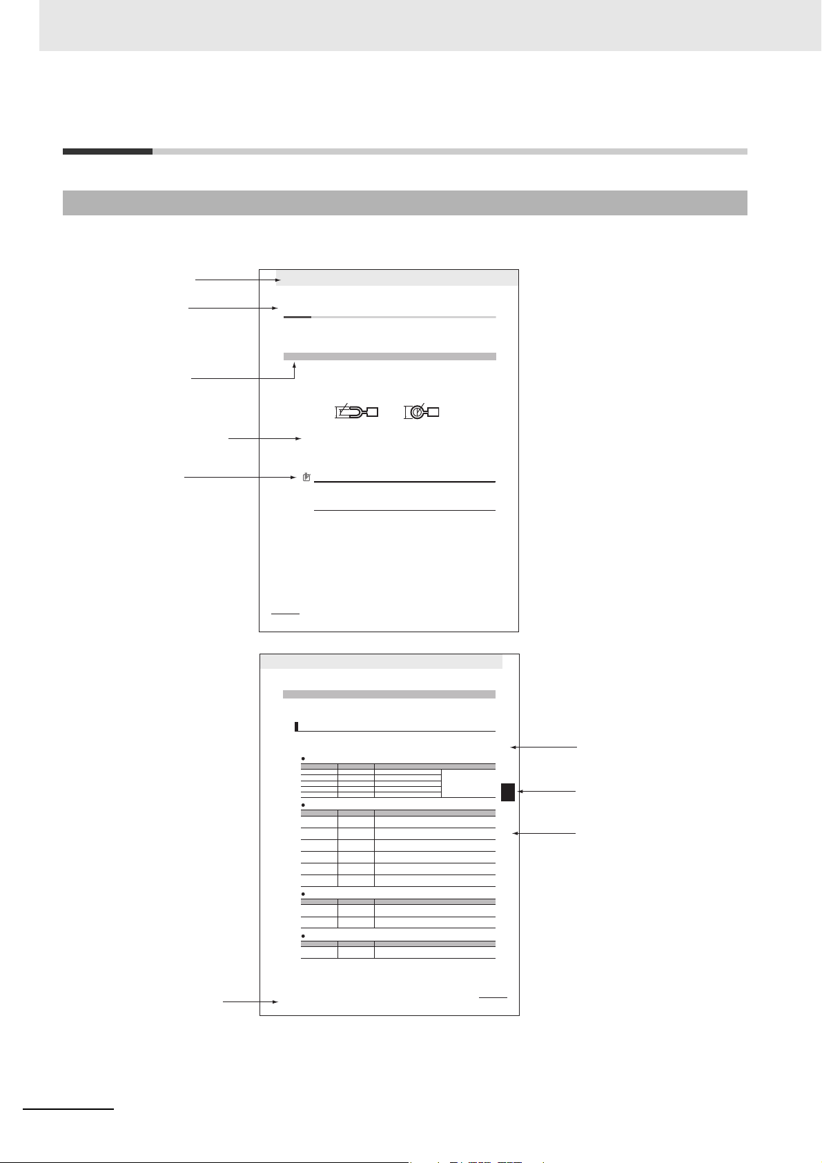
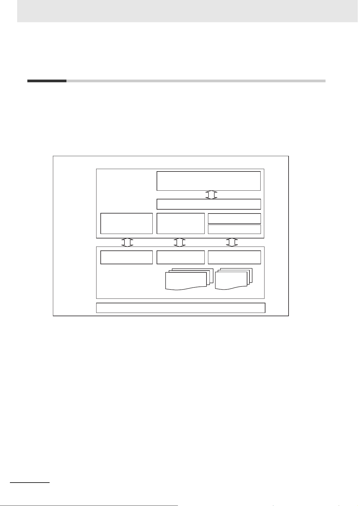
Indexes
Indicates the chapter number
of the current page.
Icon
(Refer to the following section.)
Clause title
Indicates the clause title
of the current page.
Operation
procedure number
Indicates operation procedure.
Section title
Name of manuals
Clause title
Indicates the chapter title
of the current page.
Section title
Indicates the section title
of the current page.
Chapter title
4 Installation and Wiring
4 - 10
GX-series EtherCAT Slave Unit User’s Manual
4-4 Connecting an External Device
Connect an external device to the I/O terminal of a Slave Unit.
The method of connection differs between Units with screw terminal blocks and Units with e-CON
connectors.
After mounting a crimp terminal to the cable of the external device to be connected, connect it to the
terminal block.
1
Mount the following crimp terminal to the signal line of the cable.
2
Connect the signal line to the terminal block.
Tighten the terminal block screws to the appropriate tightening torque of 0.5 N • m.
The terminal block is removable; remove the left and right screws if it is necessary to remove
the terminal block to connect the signal line.
Precautions for Correct Use
To remove the terminal block from the Slave Unit, loosen the left and right mounting screws
alternately. When mounting the terminal block as well, tighten the left and right screws
alternately.
If you tighten or loosen only one of the screws all the way without tightening or loosening the
other screw using an electric screwdriver, the terminal block will be distorted and cracked.
4-4-1 Connecting to a Screw Terminal Block
6.0 mm max.
6.0 mm max.
φ3.2 mm min.
3.2 mm min.
4 - 11
4 Installation and Wiring
GX-series EtherCAT Slave Unit User’s Manual
4-4 Connecting an External Device
4
4-4-2 Connecting to e-CON Connector Terminals
Connect the dedicated e-CON connector to the cables of the external device to be connected and then
connect it to the connector terminal.
The wire size and sheath diameter of applicable cables vary by the type of e-CON connector.
Use the next table to check that the e-CON connectors to be used conform to the wire size and sheath
diameter of the cables of the connected device.
Tyco Electronics connectors
Sumitomo 3M connectors
Panasonic Electric Works connectors
OMRON connectors
4-4-2 Connecting to e-CON Connector Terminals
Checking the e-CON connector and cable wire size
Model Housing color Applicable wire range
3-1473562-4 Orange Sheath diameter: 0.6 to 0.9 mm
Cross-sectional area: 0.08 to
0.5 mm
2
1-1473562-4 Red Sheath diameter: 0.9 to 1.0 mm
1473562-4 Yellow Sheath diameter: 1.0 to 1.15 mm
2-1473562-4 Blue Sheath diameter: 1.15 to 1.35 mm
4-1473562-4 Green Sheath diameter: 1.35 to 1.60 mm
Model Housing color Applicable wire range
37104-3101-000FL Red
AWG26 (0.14mm
2
) to AWG24 (0.2mm2)
Sheath diameter: 0.8 to 1.0 mm
37104-3122-000FL Yellow
AWG26 (0.14mm
2
) to AWG24 (0.2mm2)
Sheath diameter: 1.0 to 1.2 mm
37104-3163-000FL Orange
AWG26 (0.14mm
2
) to AWG24 (0.2mm2)
Sheath diameter: 1.2 to 1.6 mm
37104-2124-000FL Green
AWG22 (0.3mm
2
) to AWG20 (0.5mm2)
Sheath diameter: 1.0 to 1.2 mm
37104-2165-000FL Blue
AWG22 (0.3mm
2
) to AWG20 (0.5mm2)
Sheath diameter: 1.2 to 1.6 mm
37104-2206-000FL Gray
AWG22 (0.3mm
2
) to AWG20 (0.5mm2)
Sheath diameter: 1.6 to 2.0 mm
Model Housing color Applicable wire range
AXF12142 Red
AWG22 (0.3mm
2
) to AWG20 (0.5mm2)
Sheath diameter: 1.2 to 2.0 mm
AXF12146 Yellow
AWG28 (0.08mm
2
) to AWG24 (0.2mm2)
Sheath diameter: 0.7 to 1.2 mm
Model Specification Applicable wire range
XN2A-1430
Spring
clamp type
AWG28 (0.08mm
2
) to AWG20 (0.5mm2)
Sheath diameter: 1.5 mm max.
How to Read the Manual
Page Structure
This manual's page structure consists of the following.
2
E3NW-ECT EtherCAT Digital Sensor Communication Unit Operation Manual (E429)
Page 7

Icon
Precautions for Safe Use
Precautions for Correct Use
Reference
The meanings of the icons used in this manual are as follows.
Indicates precautions on what to do and what not to do to ensure using the product safely.
Indicates precautions on what to do and what not to do to ensure proper operation and
performance.
This explains useful tips and reference information when using the product.
E3NW-ECT EtherCAT Digital Sensor Communication Unit Operation Manual (E429)
3
Page 8

Structure of This Manual
This manual consists of the following chapters.
Chapters Contents
Chapter 1 EtherCAT Network
Chapter 2
Chapter 3 Basic Usage Procedures
Chapter 4 Installation and Wiring
Chapter 5 EtherCAT Communications Explains the details of EtherCAT communications.
Chapter 6 E3NW-ECT Hardware specifications Explains the E3NW-ECT Hardware specifications.
Chapter 7 E3NW-ECT Functional specifications Explains the E3NW-ECT Functional specifications.
Chapter 8 Troubleshooting and Maintenance
Appendices Appendices
EtherCAT Sensor Communication
Unit
Explains about the EtherCAT features and the network
configuration.
Overviews the E3NW-ECT EtherCAT Sensor
Communication Unit and its various types.
Explains the setup method and usage procedures by using
simple system setup examples.
Explains how to install Slave Units, and how to connect and
wire the EtherCAT network and power supply.
This contains troubleshooting and inspection methods
intended for individuals to handle abnormalities and
conduct regular inspections.
The appendices give an overview of the objects and
precautions on their use, and describes the specifications
of the E3NW-DS Distributed Sensor Unit.
4
E3NW-ECT EtherCAT Digital Sensor Communication Unit Operation Manual (E429)
Page 9

Terms and Conditions Agreement
Warranty, Limitations of Liability
Warranties
Exclusive Warranty
Omron’s exclusive warranty is that the Products will be free from defects in materials and workmanship for a period of twelve months from the date of sale by Omron (or such other period expressed in
writing by Omron). Omron disclaims all other warranties, express or implied.
Limitations
OMRON MAKES NO WARRANTY OR REPRESENTATION, EXPRESS OR IMPLIED, ABOUT
NON-INFRINGEMENT, MERCHANTABILITY OR FITNESS FOR A PARTICULAR PURPOSE OF
THE PRODUCTS. BUYER ACKNOWLEDGES THAT IT ALONE HAS DETERMINED THAT THE
PRODUCTS WILL SUITABLY MEET THE REQUIREMENTS OF THEIR INTENDED USE.
Omron further disclaims all warranties and responsibility of any type for claims or expenses based
on infringement by the Products or otherwise of any intellectual prop erty right.
Buyer Remedy
Omron’s sole obligation hereunder sh all b e, at Omron ’s election, to (i) replace (in the form origina lly
shipped with Buyer responsible for labor charges for removal or replacement thereof) the non-complying Product, (ii) repair the non-complying Product, or (iii) repay or credit Buyer an amount equal
to the purchase price of the non-complying Product; provided that in no event shall Omron be
responsible for warranty, repair, indemnity or any other claims or expenses regarding the Products
unless Omron’s analysis confirms that the Products were properly handled, stored, installed and
maintained and not subject to contam ination, abuse, misuse or inappropriate modification. Retur n of
any Products by Buyer must be approved in writing by Omron before shipment. Omron Companies
shall not be liable for the suitability or unsuitability or the results from the use of Products in combination with any electrical or electronic components, circuits, system assemblies or any other materials or substances or environments. Any advice, recommendations or information given orally or in
writing, are not to be construed as an amendment or addition to the above warranty.
See http://www.omron.com/global/ or contact your Omron representative for published information.
Limitation on Liability; Etc
OMRON COMPANIES SHALL NOT BE LIABLE FOR SPECIAL, INDIRECT, INCIDENTAL, OR CONSEQUENTIAL DAMAGES, LOSS OF PROFITS OR PRODUCTION OR COMMERCIAL LOSS IN ANY
WAY CONNECTED WITH THE PRODUCTS, WHETHER SUCH CLAIM IS BASED IN CONTRACT,
WARRANTY, NEGLIGENCE OR STRICT LIABILITY.
Further, in no event shall liability of Omron Companies exceed the individual price of the Product on
which liability is asserted.
E3NW-ECT EtherCAT Digital Sensor Communication Unit Operation Manual (E429)
5
Page 10

Application Considerations
Suitability of Use
Omron Companies shall not be responsible for conformity with any standards, codes or regulations
which apply to the combination of the Product in the Buyer’s application or use of the Product. At
Buyer’s request, Omron will provide applicable third party certification documents identifying ratings
and limitations of use which apply to the Product. This information by itself is not sufficient for a complete determination of the suitability of the Product in combination with the end product, machine, system, or other application or use. Buyer shall be solely responsible for determining appropriateness of
the particular Product with respect to Buyer’s application, product or system. Buyer shall take application responsibility in all cases.
NEVER USE THE PRODUCT FOR AN APPLICATION INVOLVING SERIOUS RISK TO LIFE OR
PROPERTY WITHOUT ENSURING THAT THE SYSTEM AS A WHOLE HAS BEEN DESIGNED TO
ADDRESS THE RISKS, AND THAT THE OMRON PRODUCT(S) IS PROPERLY RATED AND
INSTALLED FOR THE INTENDED USE WITHIN THE OVERALL EQUIPMENT OR SYSTEM.
Programmable Products
Omron Companies shall not be responsible for the user’s programming of a programmable Product, or
any consequence thereof.
Disclaimers
Performance Data
Data presented in Omron Company websites, catalogs and other materials is provided as a guide for
the user in determining suitability and does not constitute a warranty. It may represent the result of
Omron’s test conditions, and the user must correlate it to actual application req uirement s. Actual perfor mance is subject to the Omron’s Warranty and Limitations of Liability.
Change in Specifications
Product specifications and accessories may be changed at a ny time based on improvem ents and other
reasons. It is our practice to change part numbers when published ratings or features are changed, or
when significant construction changes are made. However, some specifications of the Product may be
changed without any notice. When in doubt, special part numbers may be assigned to fix or establish
key specifications for your application. Please consult with your Omron’s representative at any time to
confirm actual specifications of purchased Product.
Errors and Omissions
Information presented by Omron Companies has been checked and is believed to be accurate; however, no responsibility is assumed for clerical, typographical or proofreading errors or omissions.
6
E3NW-ECT EtherCAT Digital Sensor Communication Unit Operation Manual (E429)
Page 11
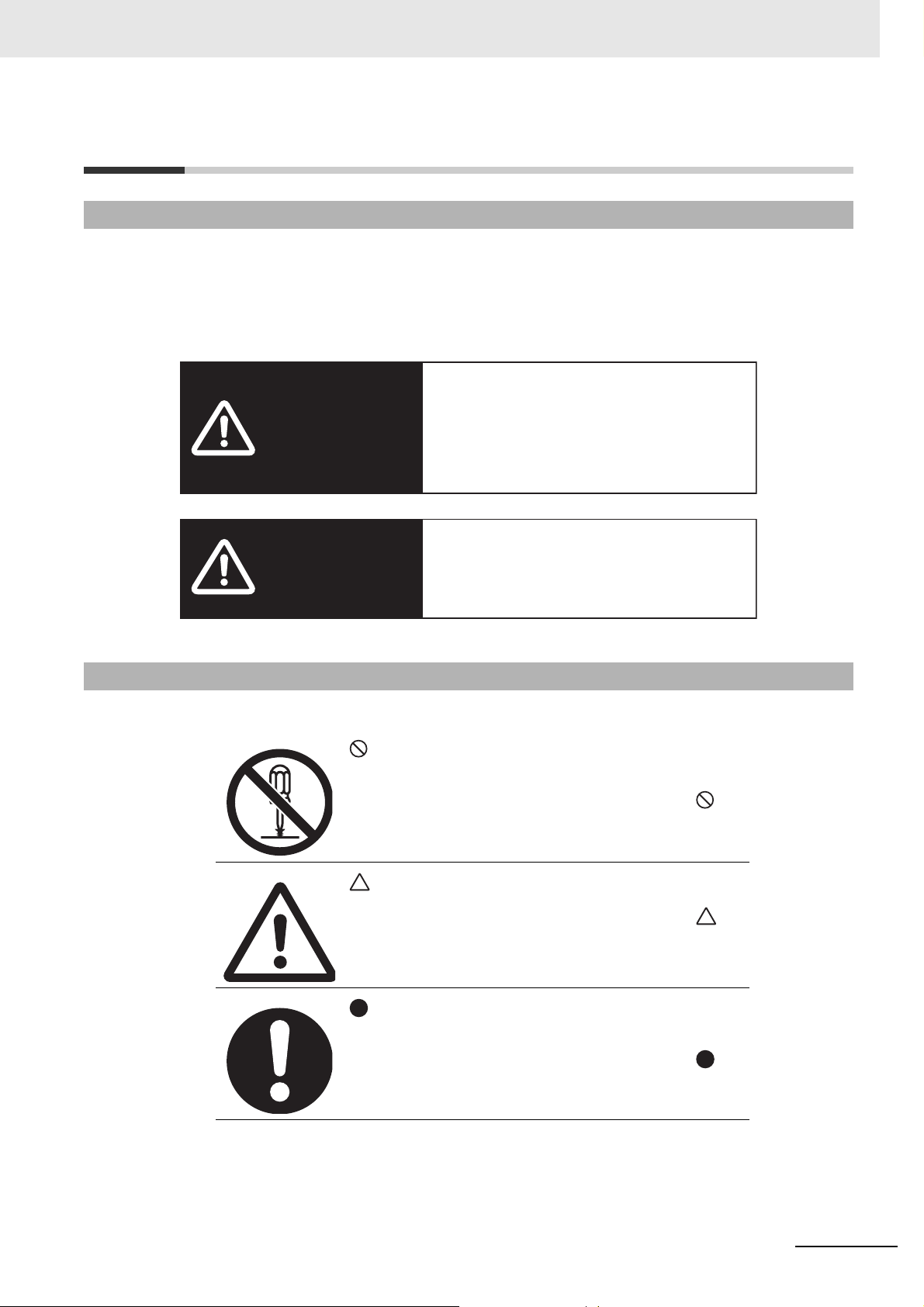
Safety Precautions
WARNING
Caution
Indicates a potentially hazardous
situation which, if not avoided, could
result in death or serious injury.
Additionally, there may be severe
property damage.
Indicates a potentially hazardous
situation which, if not avoided, may
result in minor or moderate injury, or
property damage.
Labels and Meanings to Ensure Safe Usage
To ensure safe usage of the EtherCA T Slave Unit, the pre cautions in this manual ar e displayed with the
following labels and symbols.
The precautions explained in this section describe important information regarding safety. These
precautions must be followed without fail.
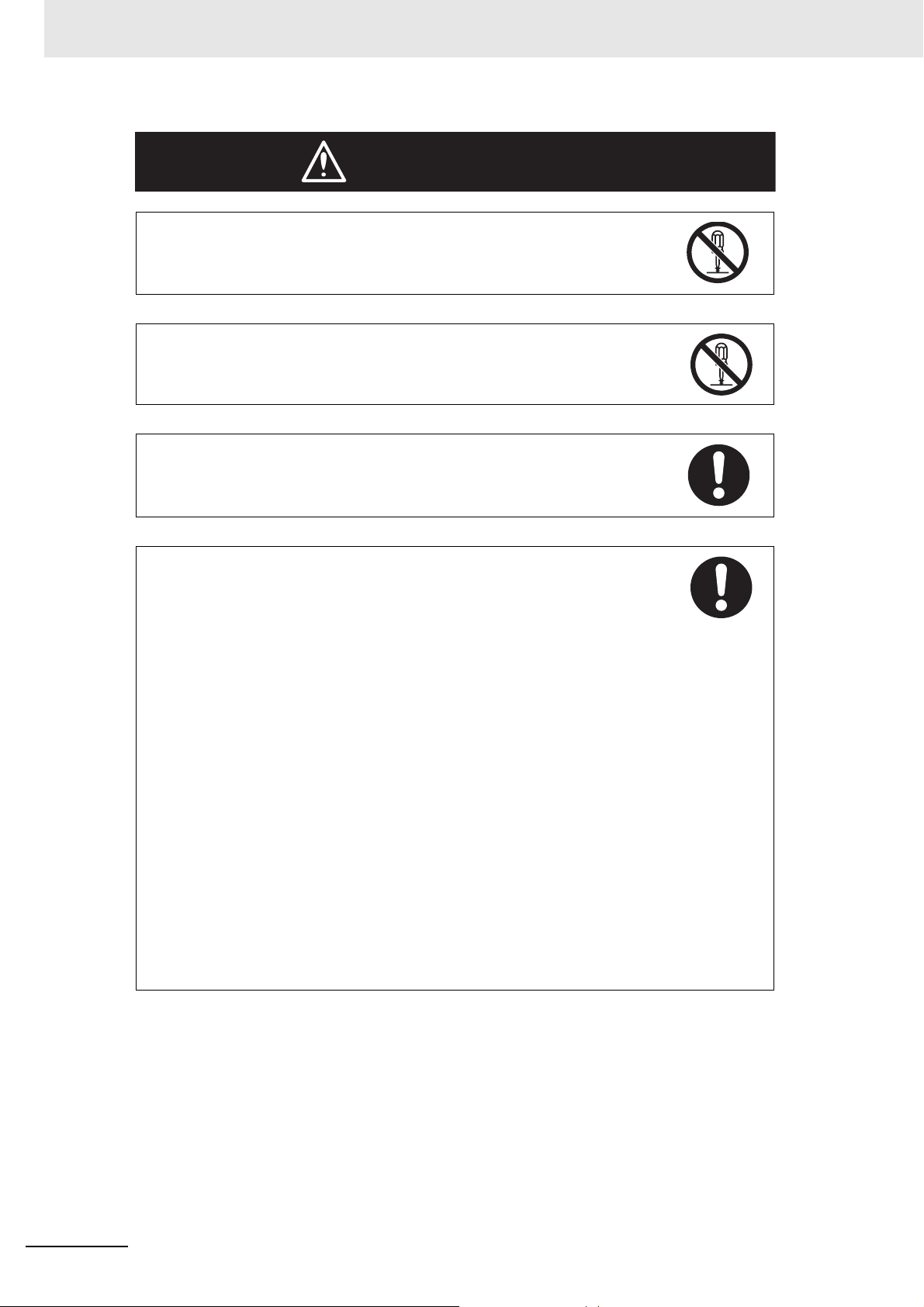
Symbols
This symbol indicates a prohibited item (an item you must not
do).
The specific instruction is indicated using text inside the .
The symbol shown to the left indicates "disassembly prohibited".
This symbol indicates caution (warnings included).
The specific instruction is indicated using text inside the .
The symbol shown to the left indicates "typical cautions".
This symbol means it is a compulsory item (an item that must
be done).
The specific instruction is indicated using text inside the .
The symbol shown to the left indicates "typical compulsory
items".
E3NW-ECT EtherCAT Digital Sensor Communication Unit Operation Manual (E429)
7
Page 12
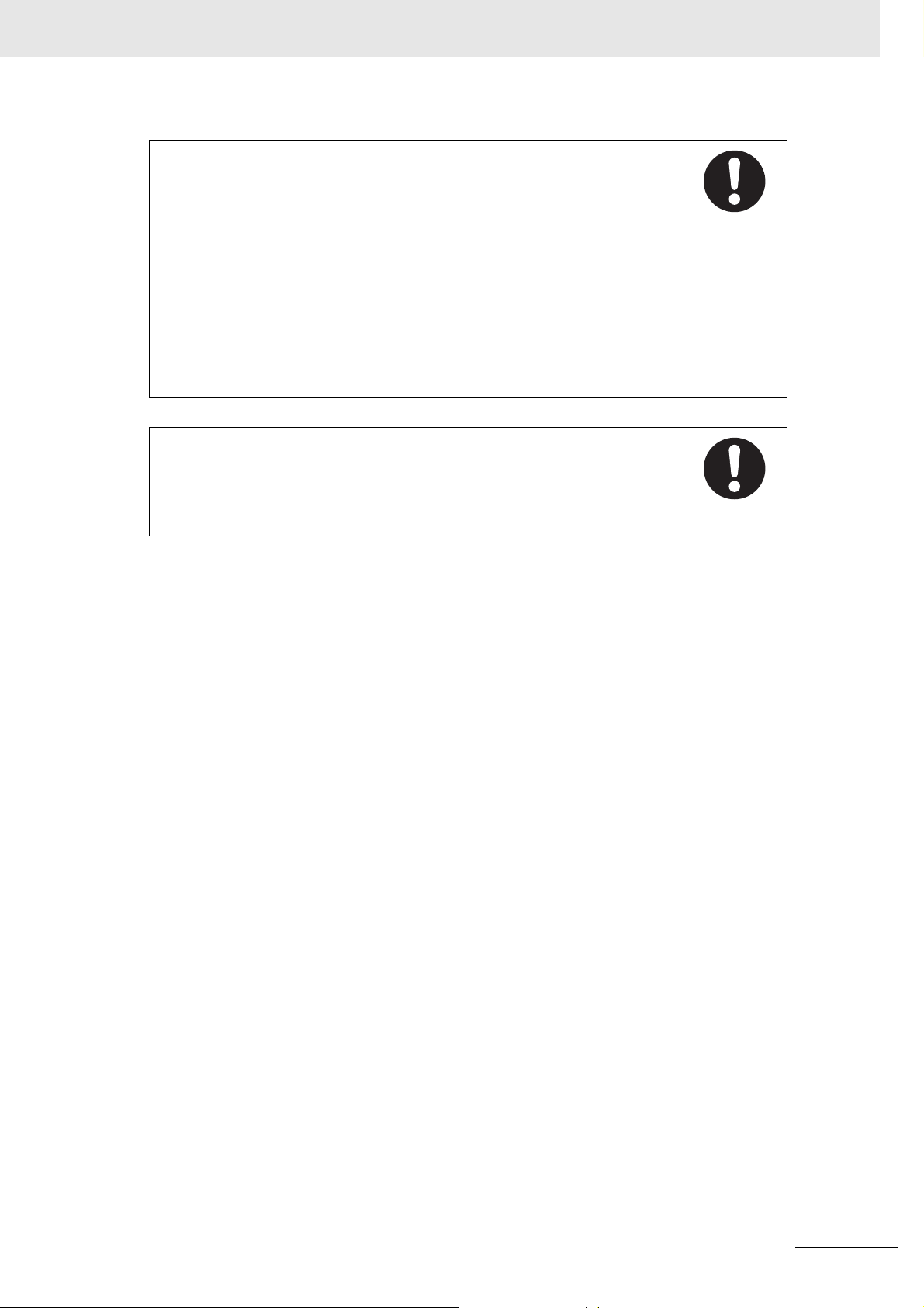
WARNING
Do not attempt to take any Unit apart and do not touch the interior of any Unit while
the power is being supplied. Also, do not turn ON the power supply while the cover
is open.
Doing any of these may result in electric shock.
Do not attempt to disassemble, repair, or modify any Units.
Doing any of these may result in electric shock.
Do not input voltages or currents exceeding the rated range to the Unit.
Using voltages or currents exceeding the rated range may cause Unit failure or fire.
Provide safety measures in external circuits (i.e., not in the Units), including the
following items, to ensure safety in the system if an abnormality occurs due to
malfunction of the PLC or another external factor affecting the PLC operation.
("PLC" includes CPU Units, other Units mounted in the PLC, and Remote I/O
Terminals.)
Not doing so may result in serious accidents.
Emergency stop circuits, interlock circuits, limit circuits, and similar safety measures
must be provided in external control circuits, not in the Units.
The PLC will turn OFF all outputs when its self-diagnosis function detects any error
or when a severe failure alarm (FALS) instruction is executed. As a countermeasure
for such problems, external safety measures must be provided to ensure safety in
the system.
The Slave Unit outputs may remain ON or OFF due to deposits on or burning of the
output relays, or destruction of the output transistors. As a countermeasure for such
problems, external safety measures must be provided to ensure safety in the
system.
When the 24-VDC output (service power supply to the PLC) is overloaded or
short-circuited, the voltage may drop and result in the outputs being turned OFF. As
a countermeasure for such problems, external safety measures must be provided to
ensure safety in the system.
Implement proper measures as part of your communications system or in your
program to ensure safety in the system even when a communications error or
malfunction occurs during remote I/O communication.
8
E3NW-ECT EtherCAT Digital Sensor Communication Unit Operation Manual (E429)
Page 13
The CPU Unit refreshes I/O even when the program is stopped (i.e., even in
PROGRAM mode). Confirm safety thoroughly in advance before changing the
status of any part of memory allocated to I/O Units, Special I/O Units, or CPU Bus
Units. Any changes to the data allocated to any Unit specifically the Special I/O
Units/CPU Bus Units may result in unexpected operation of the loads connected to
the Unit.
• Transferring I/O memory data to the CPU Unit with a Programming Device (PC
tool).
• Changing present values in memory with a Programming Device.
• Force-setting/-resetting bits with a Programming Device.
• Transferring I/O memory files from a memory card or EM file memory to the CPU
Unit.
• Tr ansferring I/O memory from a host computer or from another PLC on a network.
Fail-safe measures must be taken by the customer to ensure safety in the event of
incorrect, missing, or abnormal signals caused by broken signal lines, momentary
power interruptions, or other causes. Not doing so may result in serious accidents.
E3NW-ECT EtherCAT Digital Sensor Communication Unit Operation Manual (E429)
9
Page 14

Precautions for Safe Use
Observe the following precautions when using the Unit.
Power Supply
• Always use the power supply voltage specified in this manual. An incorrect voltage may result in
malfunction or burning.
• Take appropriate measures to ensure that the specified power with the rated voltage and
frequency is supplied. Be particularly careful in places where the power supply is unstable. An
incorrect power supply may result in malfunction.
• Always turn OFF the power supply to the PLC, Slave Units and other Units before attempting any
of the following. Not turning OFF the power supply may result in malfunction or electric shock.
• Assembling any Units (Expansion Units).
• Removing or attaching the terminal blocks or connectors to Slave Unit.
• Replacing parts (e.g., relays).
• Setting the DIP switch or the node address switches
• Connecting cables or wiring the system.
Installation
• Before touching a Unit, be sure to first touch a grounded metallic object in order to discharge any
static build-up. Not doing so may result in malfunction or damage.
• Make sure that the terminal blocks, communications cables, and other items with locking devices
are properly locked into place. Improver locking may result in malfunction.
• Mount the Units securely using DIN track.
• Make sure that all Slave Unit mounting screws and cable connector screws are tightened to the
torque specified in this manual. Incorrect tightening torque may result in malfunction.
• Make sure that all terminal block screws are tightened to the torque specified in this manuals.
Incorrect tightening torque may result in fire, malfunction, or failure.
• Always use the specified communications cable s an d co nn e cto rs .
• Do not extend connection distances or the number of connected nodes beyond the ranges given
in the specifications.
• When there are multiple systems, keep the cables unbundled and separated by at least 5 mm to
prevent unstable operation due to interference.
Wiring
• Turn the power on after checking that the wiring and switch settings are correct.
• Use the correct wire tools to wire the Unit.
• Confirm the polarity of all terminals before wiring them.
• Do not allow foreign matter to enter the Units when wiring and installing the Units.
• Observe the following precautions when wiring the communica tions cable.
• Separate the communications cables from the power lines or high-tension lines.
• Do not bend the communications cables past their natural bending radius.
• Do not pull on the communications cables.
• Do not place heavy objects on top of the communications cables.
• Always lay communications cable inside ducts.
• Turn OFF the power of PLC and all the Slave Units before wiring the communication cables.
• Do not apply voltages to the Input Slave Units in excess of the rated input voltag e. Excess voltage
or loads may result in burning.
10
E3NW-ECT EtherCAT Digital Sensor Communication Unit Operation Manual (E429)
Page 15

• Do not apply voltages or connect loads to the Outputs Slave Units in excess of the maximum
switching capacity. Excess voltage or loads may result in burning.
Handling
• When transporting the product, use special packing boxes, and protect it from being exposed to
excessive vibration or impact during transportation.
• Do not bend cables past their natural bending radius or pull on cables.
• After replacing Units, resume operation only af ter tran sferring to the new CPU Unit and/or Special
I/O Units the contents of the DM Area, HR Area, and other data required for resuming operation.
Not doing so may result in unexpected operation.
• Check the user program for proper execution before actually running it on the Unit. Not checking
the program may result in unexpected opera tio n .
• When replacing relays or other parts, be sure to confirm that the ratings of the new part are
correct. Not doing so may result in malfunction or burning.
• Confirm that no adverse effect will occur in the system before attempting any of the following.
• Changing the operating mode of the PLC.
• Setting/resetting any bit in memory.
• Changing the present value of any word or any set value in memory.
• Do not use thinner when cleaning. Use commercially available alcohol.
External Circuits
• Install external breakers and t ake other safety me asures aga inst short-circuiting in external wiring .
Applicable standards
• EN61326-1
• Electromagnetic environment : Industrial electromagnetic environment
(EN/IEC 61326-1 Table 2)
E3NW-ECT EtherCAT Digital Sensor Communication Unit Operation Manual (E429)
11
Page 16

Precautions for Correct Use
• Wire all connections correctly according to instructions in this manual.
Failure to install them may result in serious accidents.
• Do not operate the control system in the following locations:
• Location subject to direct sunlight.
• Locations subject to temperatures or humidity outside the range specified in the specifications.
• Locations subject to condensation as the result of severe changes in temperature.
• Location subject to corrosive or flammable gases.
• Location subject to dust (especially iron dust) or salts.
• Location subject to exposure to water, acid, oil, chemicals, etc.
• Locations subject to shock or vibration.
• Always use the DIN Track End Plates that are provided, and make sure that the Unit is mounted
securely to the DIN Track.
• Confirm voltage specifications when wiring communications, the power supply, and I/O crossovers.
Incorrect wire may result in malfunction.
• Wire all connections correctly according to instructions in this manual.
• Use the correct wiring materials to wire the Unit.
• Take appropriate and sufficient countermeasures when installing systems in the following locations:
• Locations subject to static electricity or other forms of noise.
• Locations subject to strong electromagnetic fields.
• Locations subject to possible exposure to radioactivity.
• Locations close to power supplies.
• Do not drop any Unit or subject any Unit to excessive shock or vibration. Otherwise, Unit failure or
malfunction may occur.
12
E3NW-ECT EtherCAT Digital Sensor Communication Unit Operation Manual (E429)
Page 17

Conformance to EC Directives
Applicable Directives
• EMC Directives
Concepts
EMC Directives
The OMRON products described in this manual are designed so that they individually comply with
the related EMC Directives so that they can be more easily built into other devices or the overall
machine. The actual products have been checked for conformity to EMC Directives (See note)*.
Whether the products conform to the standar ds in th e system used by the customer, however,
cannot be checked by OMRON and must be checked by the customer. EMC-related performance of
the OMRON devices that comply with EC Directives will vary depending on the configuration, wiring,
and other conditions of the equipment or control panel on which the OMRON devices are installed.
The customer must, therefore, perform the final check to confirm that devices and the overall
machine conform to EMC standards.
* Note: Applicable EMC (Electromagnetic Compatibility) standards are as follows:
EMS (Electromagnetic Susceptibility): EN 61326-1
EMI (Electromagnetic Interference): EN 61326-1
Conformance to EC Directives
The OMRON products described in this manual comply with the related EMC Directives. To ensure that
the machine or device in which the products are used complies with EC Directives, the products must
be installed as follows:
• The products must be installed within a control panel.
• A DC power supply with reinforced insulation or double insulation that can maintain a stable output
even if the input is interrupted for 10 ms must be used for communication s power , inter nal power , an d
I/O power. The OMRON S8JX-series Power Supply is recommended. (See note.)*
Products complying with EC Directives also conform to the Emission Standards (EN 61326-1).
•
Radiated emission characte ris tics (10-m regulations) may vary depending on the configuration of the
control panel used, other devices connected to the control panel, wiring, and other conditions. You must
therefore confirm that the overall machine or equipment complies with EC Directives.
• Conformance with the EC Directives was confirmed with a system configuration using I/O wiring
lengths of less than 30 m.
* Note: Conformance with the EMC Directive was confirmed when using the recommended power supply.
E3NW-ECT EtherCAT Digital Sensor Communication Unit Operation Manual (E429)
13
Page 18

®
Related Manuals
The following manuals also deal with EtherCAT. Refer to them for details.
Man No. Name of manuals Contents
CJ Series
W487
W446
W500
W501
W505
W503
W504
Position Control Units
Operation Manual
CX-Programmer
Operation Manual
NJ-series CPU Unit Hardware
User’s Manual
NJ/NX-series CPU Unit Software
User’s Manual
NJ/NX-series CPU Unit Built-in
EtherCAT Port User’s Manual
NJ/NX-series Troubleshooting
Manual
Sysmac Studio Ve rsion 1
Operation Manual
Explains the setup and operation procedures of the
EtherCAT Position Control Unit s (CJ1W-NCx81/x82) which
functions as a master.
Explains the operations method of the Windows-based
programming tool CX-Programmer.
Explains the overall NJ-series System and the following
items for the NJ501 CPU Units.
• Features and system configuration
• Overview
• Part names and functions
• General specifications
• Installation and wiring
• Maintenance and inspection
Use this manual together with the NJ-series CPU Unit
Software User’s Manual (Cat. No. W501).
Explains the following items for NJ-series CPU Units.
• CPU Unit operation
• CPU Unit functions
• Initial settings
• Languages and programming based on IEC 61131-3.
Use this manual together with the NJ-series CPU Unit
Hardware User’s Manual (Cat. No. W500).
Explains the built-in EtherCAT port.
An overview is provided and the configuration, functions,
and setup are described.
Use this manual together with the NJ-series CPU Unit
Hardware User’s Manual (Cat. No. W500) and the
NJ-series CPU Unit Software User’s Manual (Cat. No.
W501).
Explains error management concepts and the individual
errors that are detected by the NJ-series System.
Use this manual together with the NJ-series CPU Unit
Hardware User’s Manual (Cat. No. W500) and the
NJ-series CPU Unit Software User’s Manual (Cat. No.
W501).
Explains the operating procedures of the Sysmac Studio.
14
E3NW-ECT EtherCAT Digital Sensor Communication Unit Operation Manual (E429)
Page 19

EtherCAT Network
This chapter explains the overview of EtherCAT network.
1-1 Overview of EtherCAT Networks . . . . . . . . . . . . . . . . . . . . . . . . . . . . . . . . . 1-2
1-1-1 Features of EtherCAT . . . . . . . . . . . . . . . . . . . . . . . . . . . . . . . . . . . . . . . . . . . . 1-2
1-1-2 Structure of EtherCAT . . . . . . . . . . . . . . . . . . . . . . . . . . . . . . . . . . . . . . . . . . . . 1-2
1-1-3 Communications types of EtherCAT . . . . . . . . . . . . . . . . . . . . . . . . . . . . . . . . . 1-4
1-1-4 Connection Examples of EtherCAT . . . . . . . . . . . . . . . . . . . . . . . . . . . . . . . . . 1-5
1-2 Configuration Elements of EtherCAT Network . . . . . . . . . . . . . . . . . . . . . . 1-6
1-2-1 Configuration Devices of EtherCAT Network . . . . . . . . . . . . . . . . . . . . . . . . . . 1-6
1-2-2 Overview of Configuration Devices . . . . . . . . . . . . . . . . . . . . . . . . . . . . . . . . . . 1-7
1
E3NW-ECT EtherCAT Digital Sensor Communication Unit Operation Manual (E429)
1 - 1
Page 20
1 EtherCAT Network
EtherCAT
Master Unit
Slave Unit Slave Unit
Slave Unit
Ethernet frame
IN
OUT
Data
•
Reading output data addressed to the local Slave Units
• Writing input data
1-1 Overview of EtherCAT Networks
1-1-1 Features of EtherCAT
EtherCAT (Ethernet Control Automation Technology) is a high-performance industrial network system
based on Ethernet system and can realize faster and more efficient communications.
Each node achieves a short communications cycle time by transmitting Ethernet frames at high speed.
Furthermore, even though EtherCAT is a unique protocol, it offers excellent general-purpose
applicability. For example, you can use Ethernet cables because EtherCAT utilizes standard Ethernet
technology for the physical layer. And the effectiveness of EtherCAT can be fully utilized not only in
large control systems that require high processing speeds and system integrity, but also in small and
medium control systems.
1-1-2 Structure of EtherCAT
EtherCAT does not send data to individual slave nodes on the network, instead, it passes Ethernet
frames through all of the slave nodes.
When frame passes through a slave node, the slave node reads and writes data in the areas allocated
to it in the frames in a few nanoseconds.
Ethernet frames sent from the EtherCAT Master Unit go through all the EtherCAT Sensor
Communication Units without stopping on the way. Once they reach th e fina l Slave Unit, they are sent
back from the final Slave Unit, pass through all Slave Units again, and return to the EtherCAT Master
Unit.
With this structure, EtherCAT secures high-speed and real-time data transmission.
1 - 2
E3NW-ECT EtherCAT Digital Sensor Communication Unit Operation Manual (E429)
Page 21
1 EtherCAT Network
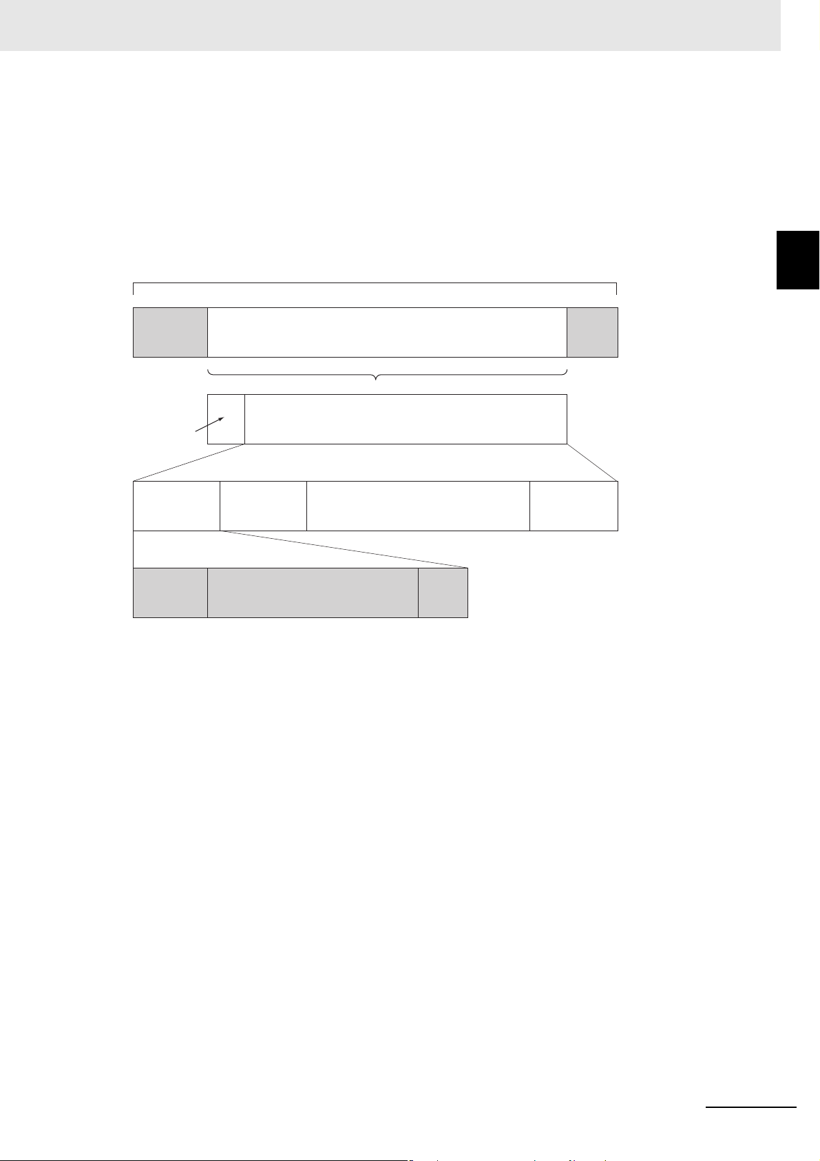
Ethernet
header
CRC
Ethernet data (Maximum 1498 bytes)
Data
Telegram
header
WKC
1...n EtherCAT telegram
EtherCAT
header
1st EtherCAT
telegram
2nd EtherCAT
telegram
n th EtherCAT
telegram
. . . . .
EtherCAT frame
Ethernet frame
WKC : Working counter
It is the "EtherCAT telegram" stored directly in an Ethernet frame that exchanges data regularly
between the EtherCAT Master Unit and Slave Units.
Each "EtherCA T te legram" is configure d with telegram hea der (dat a length, in cluding addr ess of one o r
more Slave Units, etc.), data, working counter (check bit).
When an Ethernet frame is compared to a "train", an EtherCAT telegram can be considered as "railway
car."
1-1 Overview of EtherCAT
Networks
1
1-1-2 Structure of EtherCAT
E3NW-ECT EtherCAT Digital Sensor Communication Unit Operation Manual (E429)
1 - 3
Page 22
1 EtherCAT Network
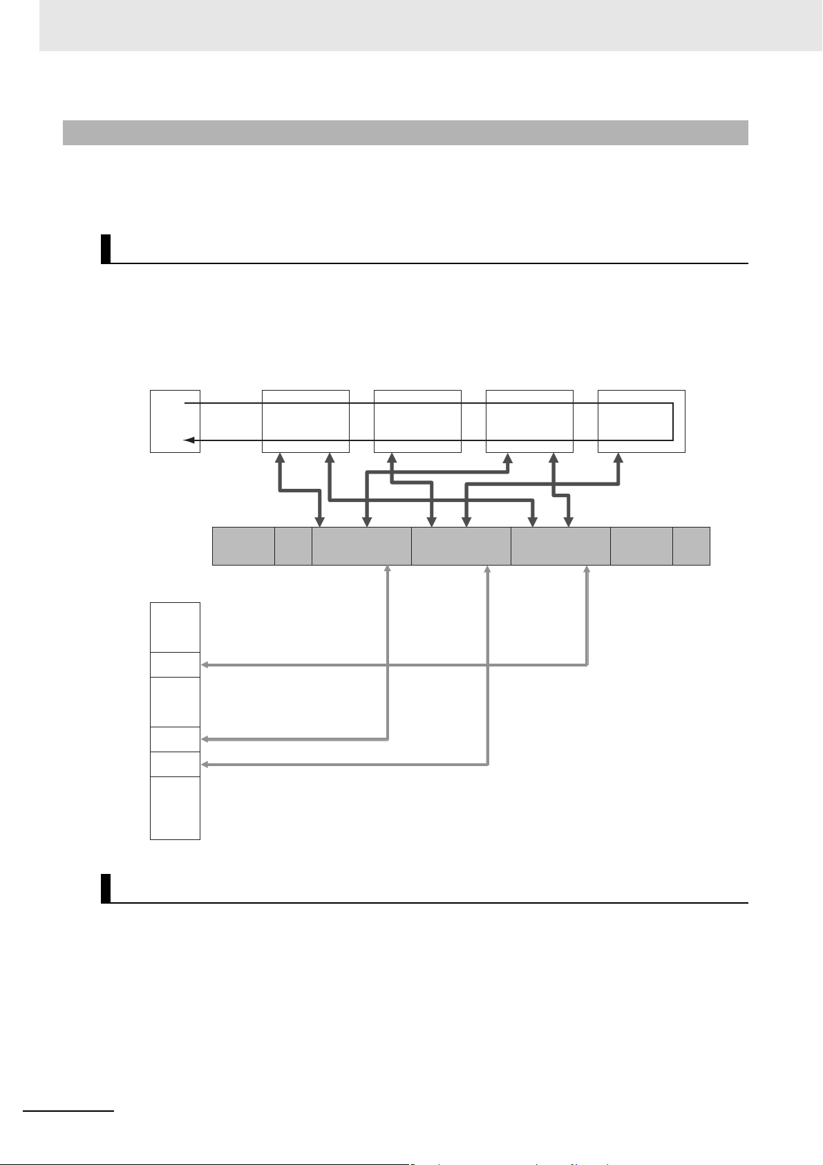
EtherCAT Master Unit
Slave Unit
Ethernet frame
Slave Unit Slave Unit
Slave Unit
Ethernet
header
EtherCAT
header
1st EtherCAT
telegram
2nd EtherCAT
telegram
3rd EtherCAT
telegram
CRC
. . .
Logic process data
.
.
.
.
.
.
.
.
.
Data a
Data b
Data c
1-1-3 Communications types of EtherCAT
EtherCAT provides the following two types of communication functions.
PDO communications are always updating data per communication cycle on EtherCAT, while SDO
communications are processed in between those updates.
Process data communications functions (PDO communications)
This communication function is used to transfer process data in real time in a fixed-cycle.
By mapping logical process data space to each node by the EtherCAT Master Unit, it achieves
fixed-cycle communications among the EtherCAT Master Unit and Slave Units.
Mailbox communications functions (SDO communications)
It refers to message communications.
At any timing, the EtherCAT Master Unit transmits commands to Slave Units and the Slave Units return
responses to the EtherCAT Master Unit.
It performs the following data communications:
• Read and write process data
• Make Slave Unit setting
• Monitor Slave Unit state
1 - 4
E3NW-ECT EtherCAT Digital Sensor Communication Unit Operation Manual (E429)
Page 23

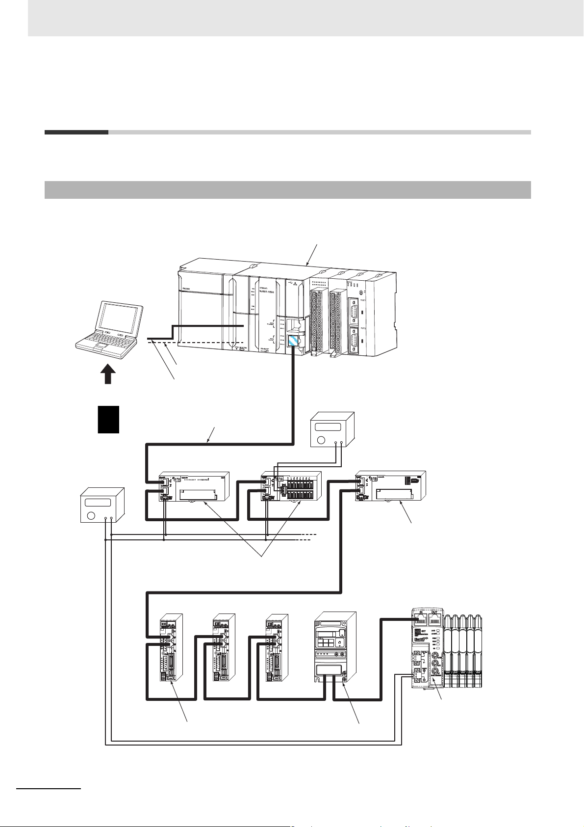
1-1-4 Connection Examples of EtherCAT
Digital I/O Slave Unit
EtherCAT Master Unit
Servo Drive
Servomotor
Inverter
E3NW-ECT EtherCAT Sensor
Communications Unit
ID211
0
1
3
2
4
5
7
6
8
9
11
10
12
13
14
15
DC24V
7mA
COM
MACH
No
.
AD042
RUN
ERC
ERH
B1A1
x10
1
x10
0
0
9
8
7
6
5
4
3
2
1
0
9
8
7
6
5
4
3
2
1
0 123 4567
8
9
10 11 12 13 14 15
ADR
ADR
ADR
1 EtherCAT Network
1-1 Overview of EtherCAT
This section explains the connection examples of EtherCAT network.
Networks
1
1-1-4 Connection Examples of EtherCAT
E3NW-ECT EtherCAT Digital Sensor Communication Unit Operation Manual (E429)
1 - 5
Page 24
1 EtherCAT Network
ID211
0
1
3
2
4
5
7
6
8
9
11
10
12
13
14
15
DC24V
7mA
COM
MACH
No
.
AD042
RUN
ERC
ERH
B1 A1
x10
1
x10
0
0
9
8
7
6
5
4
3
2
1
0
9
8
7
6
5
4
3
2
1
0 1 2 3 4 5 6 7
8
9
10 11 12 13 14 15
ESI file
PC
(Configuration Tool)
Peripheral port connection
RS-232C port connection
ADR
ADR
ADR
Communications cable
Unit power supply
I/O power supply
Digital I/O Slave Unit
Analog I/O Slave Unit
Servo Drive Inverter
E3NW-ECT EtherCAT Sensor
Communications Unit
EtherCAT Master Unit
1-2 Configuration Elements of EtherCAT
Network
This section explains the configuration devices and usages of EtherCAT network.
1-2-1 Configuration Devices of EtherCAT Network
The devices composing an EtherCAT network are shown in the figure below.
1 - 6
E3NW-ECT EtherCAT Digital Sensor Communication Unit Operation Manual (E429)
Page 25

1 EtherCAT Network
1-2 Configuration Elements of
1-2-2 Overview of Configuration Devices
The overview of each configuration device is as follows:
EtherCAT Master Unit
Administers the EtherCAT network, monitors the state of Slave Units, exchanges I/O data with Slave
Units.
EtherCAT Slave Unit
Outputs data received from the EtherCAT Master Unit through the EtherCAT network, or sends input
data to the EtherCAT Slave Unit through the EtherCAT network.
There are Digital I/O Slave Unit and Analog I/O Slave Unit.
Configuration Tool
It is a PC software for making setting of the EtherCAT network and each Slave Unit.
It can be used either by connecting to the EtherCAT Ma ste r Unit or as a substitute of the EtherCAT
Master Unit.
EtherCAT Network
1
1-2-2 Overview of Configuration Devices
Communications cable
Uses cables of Ethernet category 5 (100BASE-TX) or higher, with double-shield (aluminum tape and
braided shielding), which are connected straight.
Refer to "4-2 Connecting to EtherCAT Network" on page 4-4.
ESI (EtherCAT Slave Information) file
Describes information specific to EtherCAT Sensor Communication Units in XML format.
You can load an ESI file into the Configuration Too l to easily allocate slave process data and make
other settings.
Refer to "5-2 EtherCAT Slave Information File (ESI File)" on page 5-3.
Unit power supply
Provides power for communications of each Slave Unit and internal operations.
Separate them from the I/O power supply when wiring.
Refer to "4-3 Connecting to Unit Power Supply and I/O Power Supply" on page 4-8.
I/O power supply
Provides power for input/output operations of external devices connected to Slave Units.
Separate from Unit power supply when wiring.
The E3NW-ECT does not require an I/O power supply.
E3NW-ECT EtherCAT Digital Sensor Communication Unit Operation Manual (E429)
1 - 7
Page 26

1 EtherCAT Network
1 - 8
E3NW-ECT EtherCAT Digital Sensor Communication Unit Operation Manual (E429)
Page 27

EtherCA T Sensor Communication
Unit
This chapter explains the overview of EtherCAT Slave Unit.
2-1 Overview of E3NW-ECT . . . . . . . . . . . . . . . . . . . . . . . . . . . . . . . . . . . . . . . . . 2-2
2-1-1 Features of E3NW-ECT EtherCAT Sensor Communication Units . . . . . . . . . . 2-2
2-2 Connectable Sensor Amplifiers . . . . . . . . . . . . . . . . . . . . . . . . . . . . . . . . . . 2-3
2-2-1 List of Sensor Amplifiers . . . . . . . . . . . . . . . . . . . . . . . . . . . . . . . . . . . . . . . . . . 2-3
2-2-2 Number of Connected Sensor Amplifiers . . . . . . . . . . . . . . . . . . . . . . . . . . . . . 2-3
2
E3NW-ECT EtherCAT Digital Sensor Communication Unit Operation Manual (E429)
2 - 1
Page 28

2 EtherCAT Sensor Communication Unit
2-1 Overview of E3NW-ECT
This section explains the overview of E3NW-ECT.
2-1-1 Features of E3NW-ECT EtherCAT Sensor Communication Units
This Sensor Communication Unit is a communications slave that pro cesses EtherCAT communications
between Digital Sensors and a PLC to monitor the ON/OFF output status and detection levels, write
parameters, and operate the Sensors.
The PDOs in EtherCAT communications allow you to monitor the ON/OFF status of the outputs or the
detection levels without any programming. The SDOs give you the ability to read and write to any
specified parameter.
Optimum Functionality and Ease of Operation Based on Unified
Specifications
The E3NW-ECT EtherCAT Sensor Communication Units are Sysmac devices.* You can use them
together with NJ-series Controller, other Machine Automation Controllers, and the Sysmac Studio
Automation Software to achieve optimum functionality and ease of operation.
* “Sysm ac devices” is a generic name for EtherCAT Sensor Communication Units and other OMRON control
components that were designed with the same communications and user interface specifications.
2 - 2
E3NW-ECT EtherCAT Digital Sensor Communication Unit Operation Manual (E429)
Page 29

2 EtherCAT Sensor Communication Unit
2-2 Connectable Sensor Amplifiers
This section explains the types of connect able sensor amplifiers with Ethe rCAT Sensor Communication
Units.
2-2-1 List of Sensor Amplifiers
Name Model Features
Smart Fiber Amplifiers E3NX-FA0 These standard fiber amplifiers are easy to use and set up.
Smart Laser Amplifier Unit E3NC-LA0
Smart Laser Amplifier Unit
(CMOS Type)
Contact-type Smart Sensors E9NC-TA0 These contact-type sensors are durable.
Color fiber amplifier E3NX-CA0 Fiber amplifier with color sensing for stable detection
Smart Fiber Amplifiers E3NX-MA0 Fiber Amplifier with Light Emission/Reception
Smart Fiber Amplifiers E3NX-FAH0 Fiber Amplifier with Near Infrared Light Emission/Reception
Smart Amplifier Separation
Proximity Unit
Smart Analog Input Unit E9NC-AA□0 Current (4 to 20 mA) Input Amplifier
Smart Analog Input Unit E9NC-VA□0 Voltage (1 to 5 V) Input Amplifier
* The E9NC-TA0 is supported from E3NW-ECT Ver 1.03. The E3NX-CA0 is supported from E3NW-ECT Ver 1.06.
The E3NX-MA0, E2NC-EA□0, E9NC-AA□0 / VA□0 are supported from E3NW-ECT Ver 1.08 of the E3NW-ECT.
You can check the version with object index 100A hex. (Refer to "A-1-4 Communication Objects" on page A-4.)
E3NC-SA0
E2NC-EA□0 Proximity Sensor Amplifier
These laser sensors use a minute spot and yet they provide
stable detection.
These laser sensors use a CMOS device that allows reliable
detection of stepped surfaces.
2-2 Connectable Sensor Amplifiers
2
2-2-1 List of Sensor Amplifiers
2-2-2 Number of Connected Sensor Amplifiers
This Sensor Communication Unit allows you to connect up to 30 Sensor Amplifiers, including th ose that
are connected to the Distributed Sensor Units.
You can connect up to 10 Sensors to a Distributed Sensor Unit.
You can connect up to eight Distribution Sensor Units in one Sensor Communication Unit.
E3NW-ECT EtherCAT Digital Sensor Communication Unit Operation Manual (E429)
2 - 3
Page 30

2 EtherCAT Sensor Communication Unit
2 - 4
E3NW-ECT EtherCAT Digital Sensor Communication Unit Operation Manual (E429)
Page 31

Basic Usage Procedures
This chapter explains the procedure of using EtherCAT Sensor Communication Units
based on specific setting examples.
3-1 Setup Examples and Basic Procedure . . . . . . . . . . . . . . . . . . . . . . . . . . . . . 3-2
3-1-1 System Setting Examples . . . . . . . . . . . . . . . . . . . . . . . . . . . . . . . . . . . . . . . . . 3-2
3-1-2 Basic Procedure . . . . . . . . . . . . . . . . . . . . . . . . . . . . . . . . . . . . . . . . . . . . . . . . 3-3
3-2 Setting and Wiring Hardware . . . . . . . . . . . . . . . . . . . . . . . . . . . . . . . . . . . . 3-4
3-2-1 Mounting and Setting EtherCAT Master Unit . . . . . . . . . . . . . . . . . . . . . . . . . . 3-4
3-2-2 Mounting and Setting Slave Units . . . . . . . . . . . . . . . . . . . . . . . . . . . . . . . . . . . 3-4
3-2-3 Wiring Communications Cables . . . . . . . . . . . . . . . . . . . . . . . . . . . . . . . . . . . . 3-4
3-2-4 Connecting Power Supplies . . . . . . . . . . . . . . . . . . . . . . . . . . . . . . . . . . . . . . . 3-4
3-2-5 Connecting fiber or Sensors head . . . . . . . . . . . . . . . . . . . . . . . . . . . . . . . . . . 3-4
3-3 Starting Communications . . . . . . . . . . . . . . . . . . . . . . . . . . . . . . . . . . . . . . . 3-5
3-3-1 Starting a System . . . . . . . . . . . . . . . . . . . . . . . . . . . . . . . . . . . . . . . . . . . . . . . 3-5
3-3-2 Setting EtherCAT Communications . . . . . . . . . . . . . . . . . . . . . . . . . . . . . . . . . 3-5
3-3-3 Starting EtherCAT Communications . . . . . . . . . . . . . . . . . . . . . . . . . . . . . . . . . 3-5
3-4 Checking Operations . . . . . . . . . . . . . . . . . . . . . . . . . . . . . . . . . . . . . . . . . . . 3-6
3-4-1 Checking Unit Displays . . . . . . . . . . . . . . . . . . . . . . . . . . . . . . . . . . . . . . . . . . . 3-6
3-4-2 Confirming Data Read and Write . . . . . . . . . . . . . . . . . . . . . . . . . . . . . . . . . . . 3-6
3-4-3 Setting Slave Unit Parameter . . . . . . . . . . . . . . . . . . . . . . . . . . . . . . . . . . . . . . 3-6
3
E3NW-ECT EtherCAT Digital Sensor Communication Unit Operation Manual (E429)
3 - 1
Page 32
3 Basic Usage Procedures
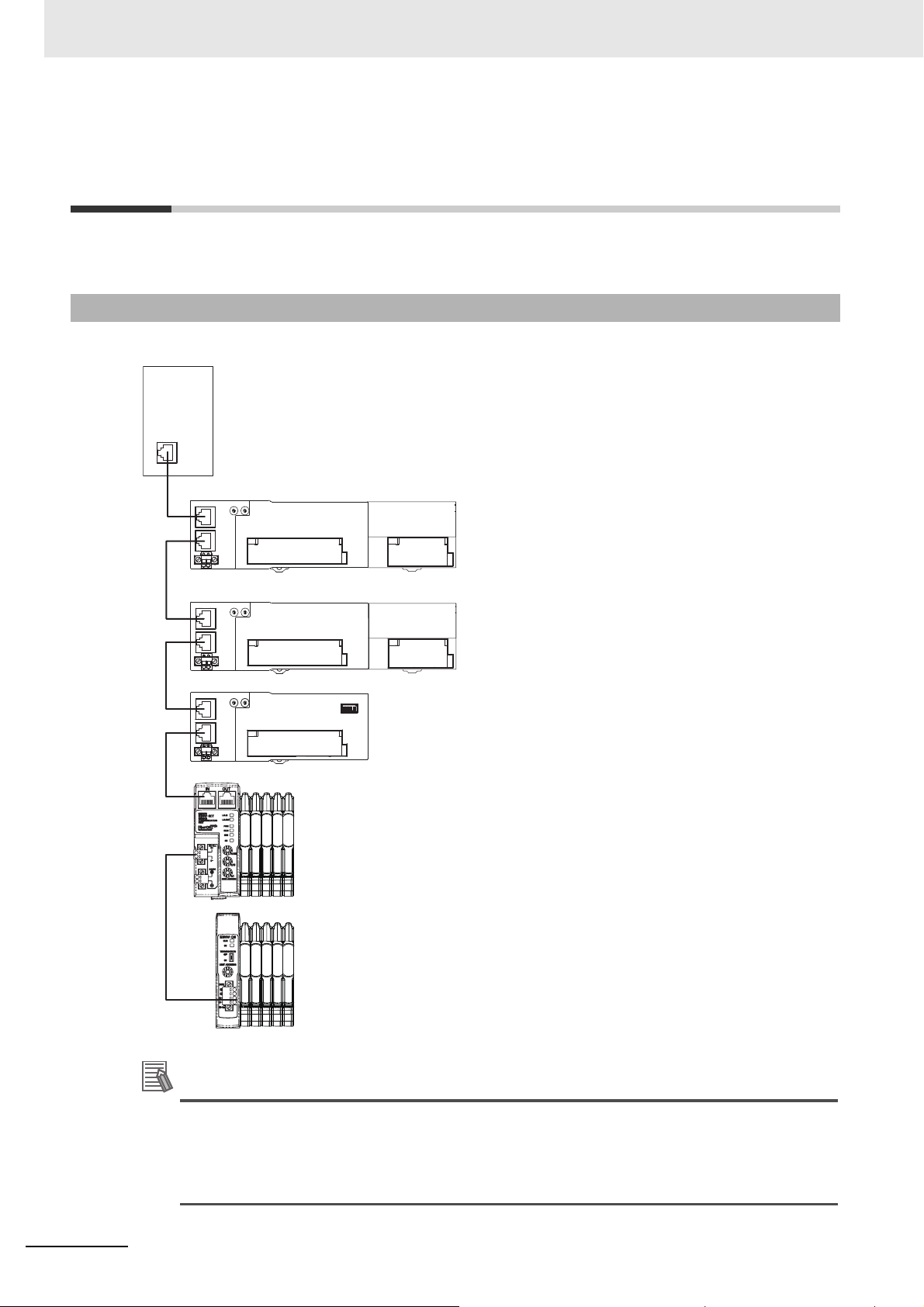
Reference
EtherCAT Master Unit
Digital I/O Slave Unit
GX-ID1611 (16 inputs)
+
Expansion Unit
XWT-ID16 (16 inputs)
Set the node address to 1.
Digital I/O Slave Unit
GX-OD1611 (16 outputs)
+
Expansion Unit
XWT-OD16 (16 outputs)
Set the node address to 2.
Analog Input Slave (4 inputs)
GX-AD0471
Set the node address to 5.
Sensor Communication Unit
E3NW-ECT
Set the node address to 6.
You can also connect up to eight E3NW-DS in one
E3NW-ECT. Up to 30 Sensor Amplifier Units can
be connected to the E3NW-ECT, and up to 10 Sensor
Amplifier Units can be connected to each E3NW-DS.
However, a total maximum of 30 Sensor Amplifier Units
can be connected in one E3NW-ECT system.
3-1 Setup Examples and Basic
Procedure
This section explains the setup method by using simple system setting examples.
3-1-1 System Setting Examples
Connect each of the following Slave Units to the EtherCAT Master Unit and make the settings.
Although it is not shown in the figure above, supply the unit power and the I/O power separately.
3 - 2
The setting example explained here is the basic setting of E3NW-ECT EtherCAT Sensor
Communication Units.
If more detailed settings are required in actual operation, refer to the manual of the EtherCAT
Master Unit. Moreover, if your system configuration includes Slave Units other than our product s,
make the setting upon referring to the manual of the relevant Slave Units.
E3NW-ECT EtherCAT Digital Sensor Communication Unit Operation Manual (E429)
Page 33

3 Basic Usage Procedures
Start
Setting and Wiring HardwareStarting CommunicationsChecking Operations
End
Checking Unit Displays
(If the DS-Bus network is used between Units)
Mounting and Setting Distributed Sensor Units
Mounting and Setting EtherCAT Master Unit
Section 3-2-2
Section 3-2-3
Section 3-2-4
Section 3-2-5
Section 3-3-1
Section 3-3-3
Section 3-3-2
Section 3-2-1
Section 3-4-1
Section 3-4-2
Section 3-4-3
Mounting and Setting Slave Units
Wiring Communications Cables
Connecting fiber or sensor head
Starting a System
Starting EtherCAT Communications
Connecting Power Supplies
Setting an EtherCAT Communications
Confirming Data Read and Write
Setting Slave Unit Parameter
Section 3-2-2
3-1-2 Basic Procedure
This is the flow of the procedures explained in the following sections.
3-1 Setup Examples and Basic Procedure
3
3-1-2 Basic Procedure
E3NW-ECT EtherCAT Digital Sensor Communication Unit Operation Manual (E429)
3 - 3
Page 34

3 Basic Usage Procedures
Reference
3-2 Setting and Wiring Hardware
Make settings and wiring of the EtherCAT Master Unit and Slave Units, and power supply.
3-2-1 Mounting and Setting EtherCAT Master Unit
Mount the EtherCAT Master Unit at the prescribed location and make settings of Unit No. and so on.
For the detailed explanation, refer to the manual of the EtherCAT Master Unit to be used.
3-2-2 Mounting and Setting Slave Units
Mount each slave and Distributed Sensor Unit in their designated locations, and then set the node
addresses and other settings.
For details, refer to each item below.
Mounting
"4-1 Mounting E3NW-ECT and Sensor Amplifiers" on page 4-2
Setting Hardware
"6-3-2 Node Address Setting Switches" on page 6-6
Set the node address.
3-2-3 Wiring Communications Cables
Connect communications cables to the EtherCAT master, slaves, and the Distributed Sensor Units.
Refer to "4-2 Connecting to EtherCAT Network" on page 4-4 for wiring procedures.
3-2-4 Connecting Power Supplies
Connect the Unit power supply to the EtherCAT master, slaves, and the Distributed Sensor Units.
In addition, connect the I/O power supply to each Slave Unit as required.
For the connection method, refer to "4-3 Connecting to Unit Power Supply and I/O Power Supply" on
page 4-8 or the wiring diagram of each Slave Unit (in pages explaining the details).
3-2-5 Connecting fiber or Sensors head
3 - 4
Connect fiber or sensor head to sensor amplifier
For the connection method, refer each sensor amplifier manual
If you connect the Distribution Sensor Unit to your network, refer to "A-2 Using Distributed
Sensor Units" on page A-51 as well.
E3NW-ECT EtherCAT Digital Sensor Communication Unit Operation Manual (E429)
Page 35

3 Basic Usage Procedures
3-3 Starting Communications
Start the system, allocate I/O data of Slave Units, and then start the EtherCAT communications.
For operational state and details of it, refer to "5-3 Communications State Transitions" on page 5-4.
3-3-1 Starting a System
Turn ON the power supply to the Units in order.
(1) Unit power supply of Slave Units (When the power is supplied, Slave Unit's [PWR] indicator is lit.)
• If you are using Distributed Sensor Units, turn ON the power supply to the Distributed Sensor Units
as well.
(2) Unit power supply of EtherCAT Master Units
3-3-2 Setting EtherCAT Communications
The following communications are performed in EtherCAT.
PDO communications (remote I/O communications)
Allocate I/O data of Slave Units to the EtherCAT Master Unit (PDO mapping) and perform PDO
communication (remote I/O communications).
For the detailed explanation of I/O data of each Slave Unit, refer to "I/O Data Allocation (PDO
Mapping)” in Chapter 7.
Note that the ESI file are used to allocate I/O data.
For the detailed explanation of the procedure, refer to the manual of the EtherCAT Master Unit to be
used and the manual of the Configuration Tool.
The maximum assignable PDO size for the E3NW-ECT is 350 bytes. (Refer to "7-2-3 Mode Setting
Functions for PDO Communications" on page 7-6 for de tails.) Do not ass ign PDOs that exceed the
maximum assignable PDO size.
3-3 Starting Communications
3
3-3-1 Starting a System
SDO communications (message communications)
For the method of using, refer to the manual of the EtherCAT Master Unit to be used.
Refer to "Appendix A - 1 Object Dictionary" for the detailed explanation of objects implemented on
E3NW-ECT EtherCAT Sensor Communication Units.
Note that the SDO communications can be used in the pre-operational state or more.
3-3-3 Starting EtherCAT Communications
Shift to the operational state (EtherCAT communications possible) to start the EtherCAT
communications.
For how to shift to the operational state, refer to the manual of the EtherCAT Master Unit to be used.
E3NW-ECT EtherCAT Digital Sensor Communication Unit Operation Manual (E429)
3 - 5
Page 36

3 Basic Usage Procedures
3-4 Checking Operations
Confirm that the LED indicators of the EtherCAT Master Unit and Slave Units are normal status and that
I/O data is correctly read and written.
Moreover, make parameter settings for Slave Units as required.
3-4-1 Checking Unit Displays
EtherCAT Master Unit
Refer to the manual of the EtherCAT Master Unit to be used.
EtherCAT Sensor Communication Units
Check that the status indicator of each Slave Unit is as follows.
Indicator State
PWR ON
L/A IN Flickering
L/A OUT Flickering (turned OFF for the terminal Slave Unit only)
RUN ON
ERR OFF
Lit red. (The number of actual connections does not agree
with the number of connections that were detected when
SS
the Unit was started.)
Lit green. (The number of actual connections agrees with
the number of connections that were detected when the
Unit was started.)
If the status indicator indicates other statuses than above, refer to "8-1 Troubleshooting" on page 8-2.
Distributed Sensor Unit
Make sure the status indicators on each slave are as described in the following table.
Indicator State
RUN Lit.
Lit red. (The number of actual connections does not agree with the number of connections
SS
that were detected when the Unit was started.)
Lit green. (The number of actual connections agrees with the number of connections that
were detected when the Unit was started.)
3-4-2 Confirming Data Read and Write
Use a Configuration Tool, such as the Sysmac Studio, to read input and output data from the EtherCAT
master to make sure the I/O data is being read and written correctly.
3-4-3 Setting Slave Unit Parameter
Make parameter settings for each Slave Unit as required via the SDO communications.
Refer to Chapter 7 Function Specifications and the pages that provide details in the Appendix for
further information on the parameters that can be set. Always set the following objects in your initial
settings for the E3NW-ECT.
• If you intend to use a Dummy Sensor, make sure to register the Dummy Sensor.
3 - 6
E3NW-ECT EtherCAT Digital Sensor Communication Unit Operation Manual (E429)
Page 37

Installation and Wiring
This chapter explains the mounting and wiring methods of the EtherCAT Slave Unit.
4-1 Mounting E3NW-E CT and Sensor Amplifiers . . . . . . . . . . . . . . . . . . . . . . . 4-2
4-1-1 Mounting Method . . . . . . . . . . . . . . . . . . . . . . . . . . . . . . . . . . . . . . . . . . . . . . . 4-2
4-1-2 Removal Method . . . . . . . . . . . . . . . . . . . . . . . . . . . . . . . . . . . . . . . . . . . . . . . . 4-3
4-2 Connecting to EtherCAT Network . . . . . . . . . . . . . . . . . . . . . . . . . . . . . . . . 4-4
4-2-1 Precautions for Network Connection . . . . . . . . . . . . . . . . . . . . . . . . . . . . . . . . 4-4
4-2-2 Preparation for Connecting Network . . . . . . . . . . . . . . . . . . . . . . . . . . . . . . . . . 4-5
4-2-3 Connecting Communications Cables and Connectors . . . . . . . . . . . . . . . . . . . 4-6
4-2-4 Connecting to Communications Cables . . . . . . . . . . . . . . . . . . . . . . . . . . . . . . 4-7
4-3 Connecting to Unit Power Supply and I/O Power Supply . . . . . . . . . . . . . 4-8
4-3-1 Precautions at Supplying Unit Power and I/O Power . . . . . . . . . . . . . . . . . . . . 4-8
4-3-2 Unit Power Supply Specifications . . . . . . . . . . . . . . . . . . . . . . . . . . . . . . . . . . . 4-8
4-3-3 Connecting the Unit Power Supply . . . . . . . . . . . . . . . . . . . . . . . . . . . . . . . . . . 4-9
4
E3NW-ECT EtherCAT Digital Sensor Communication Unit Operation Manual (E429)
4 - 1
Page 38

4 Installation and Wiring
DIN Track
Sensor Communication Unit
Push into place.
4-1 Mounting E3NW-ECT and Sensor
Amplifiers
This section describes how to mount and remove the E3NW-ECT and individual Amplifiers to the DIN
Track.
4-1-1 Mounting Method
Use the following procedure to mount the Units.
1. Hook the upper portion of the Unit on the DIN Track.
2. Press the lower portion of the Unit against the DIN Track.
3. Remove the protective cap from the right side of the Sensor Communication Unit. Then, slide the
Sensor Amplifier Units against the Sensor Communication Unit with the tabs aligned with the
notches in the connector area. Press them together until they click into place.
Sensor Amplifier Units
4. Use the DIN Track End Plates (PFP-M) that are provided to r emove any gap s between the Unit s and
secure them in place. Replace the protective cap that you removed in step 3 to the Sensor Amplifier
on the right end.
4 - 2
Protective cap
E3NW-ECT EtherCAT Digital Sensor Communication Unit Operation Manual (E429)
DIN Track
End Plates
Page 39
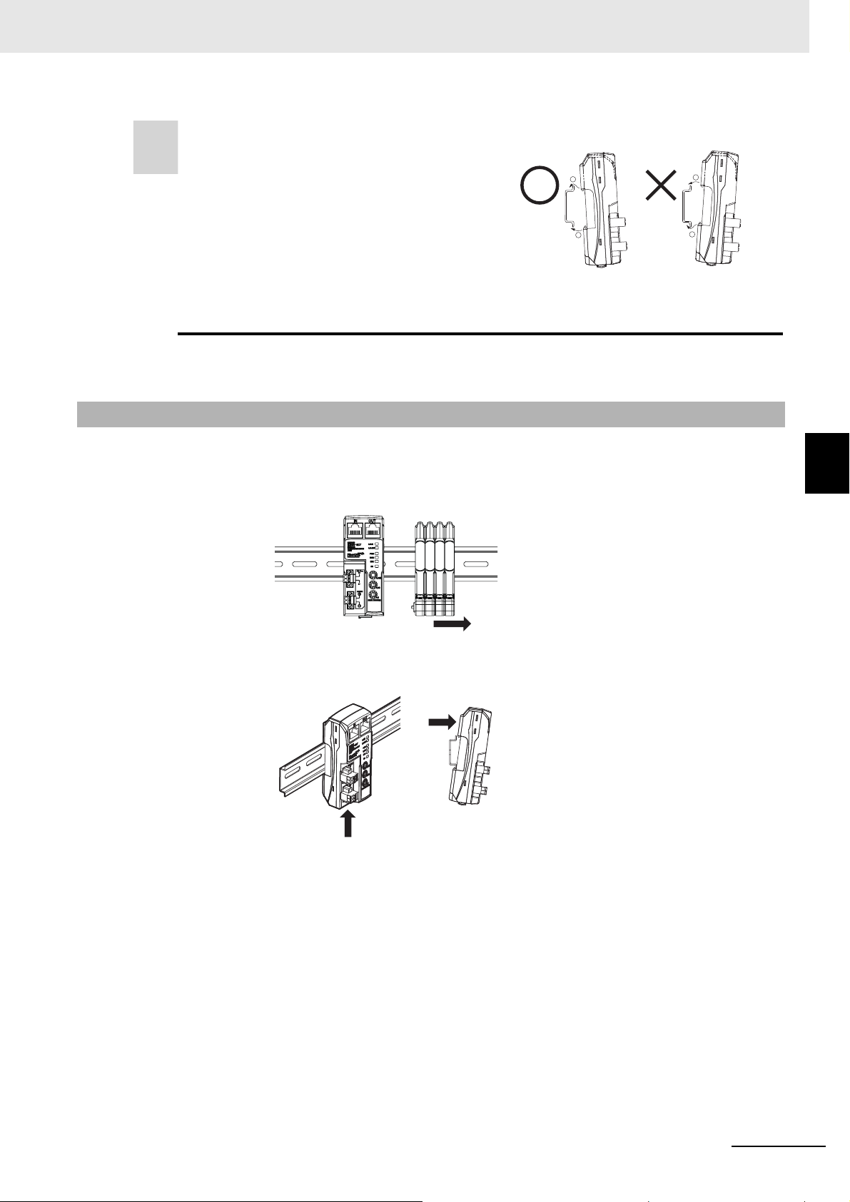
Do not perform steps 1 and 2 in the reverse order. This
2
1
1 1
2 2
Perform step 1 and
then step 2.
Do not perform step
2 before step 1.
may reduce the mounting strength.
After you finish these steps, make sure the E3NW-ECT is securely in place.
4-1-2 Removal Method
Use the following procedure to remove the Units.
1. Slide the Sensor Amplifier Units away and remove the Sensor Communication Unit first.
4 Installation and Wiring
4-1 Mounting E3NW-ECT and Sensor Amplifiers
4
4-1-2 Removal Method
2. Keep the Sensor Communication Unit pressed against the DIN Track as you lift it up, and then off.
E3NW-ECT EtherCAT Digital Sensor Communication Unit Operation Manual (E429)
4 - 3
Page 40

4 Installation and Wiring
4-2 Connecting to EtherCAT Network
This section explains how to lay down EtherCAT network.
4-2-1 Precautions for Network Connection
Observe the precautions below when laying down the EtherCAT network.
Precautions at laying down network
• When laying down an EtherCAT network, take sufficient safety measures and construct the network
according to the standards. We recommend to request specialized constructors familiar with the
safety measures and standards to perform the laying operation.
• Do not lay down EtherCAT network devices near any devices generating noise.
If there is no choice but to lay them down in a noisy enviro nme nt, make sur e to take noise measures
such as housing each device in metal cases.
Precautions at laying down communications cables
• Check the following items for communications cables to be used.
• Are there any disconnected cables?
• Are any cables short-circuited?
• Are there any problems in connector connections?
• To connect a cable to communications connector of each device, in sert i t securely until the connector
of the communications cable is locked.
• Lay down and wire the communications cables separately from high-voltage electrical power lines.
• Do not lay down the cables near devices generating noise.
• Do not lay down the cables in high-temperature and high-humidity environment.
• Use the cables in locations without powder dust and oil mist.
• There is a limit to the bending radius of communications cables. Check the specification of
communications cables to be used for the information on bending radius.
4 - 4
E3NW-ECT EtherCAT Digital Sensor Communication Unit Operation Manual (E429)
Page 41
Precautions for Correct Use
Reference
4-2-2 Preparation for Connecting Network
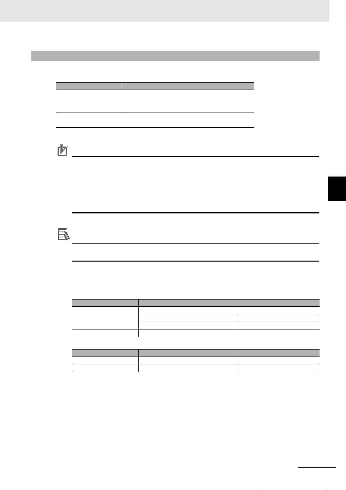
Prepare the following devices.
4 Installation and Wiring
Product name Comment
Twisted-pair cable
(Cables with connectors
below are also allowed.)
RJ45 connector
100BASE-TX (Category 5 or higher)
Double-shield (aluminum tape + braided shielding)
Category 5 or higher
Shielded
• The maximum cable length between connected nodes is 100 m. Note that some cable s do not
guarantee 100 m. In general, if the conductors are strand wire, the transmission performance
will be lower than solid wire and the operation at 100-m distance cannot be guaranteed.
Confirm details with the cable manufacturer.
• When selecting connectors, check that the cables to be used conform to connectors. Items to
be checked include conductor size, conductor wire type (solid wire/twisted wire, 2/4 pairs), and
outer diameter.
We recommend cables with double, aluminum tape and braided shielding, taking noise
resistance into consideration.
4-2 Connecting to EtherCAT Network
4
4-2-2 Preparation for Connecting Network
Recommended Parts
The recommended products for the par ts described above are listed below.
• Sizes and Conductor Pairs: AWG 24 × 4 Pairs
Part Manufacturer Model
Tonichi Kyosan Cable, Ltd. NETSTAR-C5E SAB 0.5×4P
Communications Cables
Connectors Panduit Corporation MPS588
• Sizes and Conductor Pairs: AWG 22 × 2 Pairs
Part Manufacturer Model
Communications Cables Kuramo Electric Co., Ltd. KETH-PSB-OMR
Connectors OMRON Corporation XS6G-T421-1
(Notes) We recommend that you use combinations of the above Cables and Connectors.
Kuramo Electric Co., Ltd. KETH-SB
SWCC Showa Cable Systems Co. Ltd. FAE-5004
E3NW-ECT EtherCAT Digital Sensor Communication Unit Operation Manual (E429)
4 - 5
Page 42

4 Installation and Wiring
Reference
White-Green
Green
White-Orange
Blue
White-Blue
Orange
White-Brown
Brown
Connector
hood
1
2
3
4
5
6
7
8
Shielded cable *
Wire color
Pin No.
White-Green
Green
White-Orange
Blue
White-Blue
Orange
White-Brown
Brown
Connector
hood
1
2
3
4
5
6
7
8
Shielded cable*
Wire color
Pin No.
4-2-3 Connecting Communications Cables and Connectors
Connect a communications cable and a connector by wiring them straight as shown below.
* Connect both ends of cable shielded wires to the connector hoods.
There are 2 types of wiring standards for Ethernet cables : "T568A" and "T568B."
The figure above shows a wiring method conforming to the standard "T568A". The wiring
method conforming to the standard "T568B" can also be used.
4 - 6
E3NW-ECT EtherCAT Digital Sensor Communication Unit Operation Manual (E429)
Page 43
Precautions for Correct Use
4-2-4 Connecting to Communications Cables
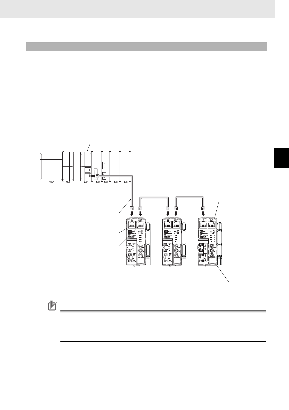
CN IN connector
CN OUT connector
EtherCAT master
Slaves
Communications cable
Do not connect anything.
Last slave
L1
L2
Ln
EtherCAT networks allow free wiring in any connection forms. Connection before and after the
E3NW-ECT EtherCAT Sensor Communication Units shall be made in daisy chain connection.
4 Installation and Wiring
Connect the communications cable from the EtherCAT Master Unit to the [CN IN] connector of the
Slave Units. Connect another the communications cable from the [CN OUT] connector of the first Slave
Unit to the [CN IN] connector of the next Slave Unit.
Note that nothing should be connected to the [CN OU T] connector o f the Slave Unit at the termina l end
of the network.
Refer to A-2 Using Distributed Sensor Units on page A-51 for connection with the Distributed Sensor
Units.
4-2 Connecting to EtherCAT Network
4
4-2-4 Connecting to Communications Cables
• The cable length between each Slave Unit (L1, L2, ... Ln) must be within 100 m.
• Connect cables securely until communications cable connectors click and are fixed in place.
• When you wire the communications cables, observe their specifications (bending radius and
E3NW-ECT EtherCAT Digital Sensor Communication Unit Operation Manual (E429)
so on) defined by the cable manufacturer.
4 - 7
Page 44

4 Installation and Wiring
Precautions for Correct Use
4-3 Connecting to Unit Power Supply
and I/O Power Supply
A unit power supply is required to connect if you use the E3NW-ECT to build the EtherCAT network.
E3NW-ECT does not require an I/O power supply.
The method for supplying power to the Unit is described below.
4-3-1 Precautions at Supplying Unit Power and I/O Power
When supplying the unit power supply and I/O power supply, take the followings into consideration for
allowable current of cables and connectors, voltage drop, and layout of power supplies.
Consideration to cable voltage drop
The power supply voltage of a Slave Unit farthest to the power supply must be within the allowable
variation range.
Supplying unit power supply and I/O power supply from multiple sources
When the unit power and I/O power are supplied from multiple power supplies instead of from one power
supply, the line current,
safety of the system at power supply errors.
If power supply errors occur
Consideration on layout and grouping of power supplies dif fer by whether you want to stop the entire
system or not when a power supply error occurs.
If you want to avoid stopping the entire system, we recommend to set power supplies at several
locations and supply power to groups of Slave Units, or take similar measures.
This has also the effects of reducing vo ltage drop and cable size and so on.
voltage drop, and cable size can be reduced.
Moreover, it is effective to secure
4-3-2 Unit Power Supply Specifications
Use a general purpose power supply that satisfies the following specifications.
Item Specification
Output voltage 24 VDC ± 10%
Output ripple 600 mVp-p
Output current
Isolation
We recommend S8JX series power supplies made by OMRON for the unit power supply for Slave
Units.
• The I/O power supply for the input section of the e-CON connector type Slave Units is shared
with the unit power supply . To calculate the output current of the Unit power supply, the curren t
consumption of the Unit power supply must include the total current consumption of the
E3NW-DS and the current consumptions of the Sensor Amplifier Units that are used.
• Select a power supply that has sufficient capacity, allowing for the inrush current at system
startup.
Has the capacity to supply power more than the total current
consumption of each Slave Unit
Between output and AC power supply as well as between output and
chassis ground
4 - 8
E3NW-ECT EtherCAT Digital Sensor Communication Unit Operation Manual (E429)
Page 45

4-3-3 Connecting the Unit Power Supply
To Unit DC24V
Power Supply
+V Terminal
−V Terminal
Unit Power
Supply Cable
Pin Terminal
Connect a cable from the 24-VDC unit power supply to the unit power supply connector on each Slave
Unit, and supply power to individual Slave Units.
Mount a pin terminal, or equivalent to the unit power supply cable so that it will not be displaced.
Do not wire a power supply to the communications path of the Distributed Sensor Units. The Units may
be damaged.
4 Installation and Wiring
4-3 Connecting to Unit Power Supply and I/O Power Supply
4
Recommended product
The following pin terminals are recommended for the unit power supply cables.
Model Applicable wire size Crimping tool Manufacturer
CRIMPFOX UD6
AI0,5-10WH
H0.5/16 orange
0.5 mm2/AWG20
2
0.5 mm
/AWG20
(Product No. 1204436)
or CRIMPFOX ZA3
series
Crimper PZ1.5
(Product No. 900599)
Also, the following screwdriver is recommended for removing pin terminals.
Model Manufacturer
XW4Z-00C OMRON
Phoenix Contact
Co., Ltd.
Weidmueller Japan Co., Ltd.
4-3-3 Connecting the Unit Power Supply
E3NW-ECT EtherCAT Digital Sensor Communication Unit Operation Manual (E429)
4 - 9
Page 46

4 Installation and Wiring
4 - 10
E3NW-ECT EtherCAT Digital Sensor Communication Unit Operation Manual (E429)
Page 47

y
EtherCAT Communications
This chapter explains the overview of EtherCAT communications.
5-1 Struc ture of CAN application protocol over EtherCAT (CoE) . . . . . . . . . . 5-2
5-2 EtherCAT Slave Information File (ESI File) . . . . . . . . . . . . . . . . . . . . . . . . . 5-3
5-3 Communications State Transitions . . . . . . . . . . . . . . . . . . . . . . . . . . . . . . . 5-4
5-4 Process Data Objects (PDO) . . . . . . . . . . . . . . . . . . . . . . . . . . . . . . . . . . . . . 5-5
5-4-1 Overview . . . . . . . . . . . . . . . . . . . . . . . . . . . . . . . . . . . . . . . . . . . . . . . . . . . . . . 5-5
5-4-2 PDO Mapping Settings . . . . . . . . . . . . . . . . . . . . . . . . . . . . . . . . . . . . . . . . . . . 5-5
5-4-3 Sync Manager PDO Assignment Settings . . . . . . . . . . . . . . . . . . . . . . . . . . . . 5-6
5-4-4 PDO Mapping . . . . . . . . . . . . . . . . . . . . . . . . . . . . . . . . . . . . . . . . . . . . . . . . . . 5-7
5-5 Service Data Object (SDO) . . . . . . . . . . . . . . . . . . . . . . . . . . . . . . . . . . . . . 5-10
5-5-1 Overview . . . . . . . . . . . . . . . . . . . . . . . . . . . . . . . . . . . . . . . . . . . . . . . . . . . . . 5-10
5-5-2 Abort Codes . . . . . . . . . . . . . . . . . . . . . . . . . . . . . . . . . . . . . . . . . . . . . . . . . . 5-10
5-6 EtherCAT Master Unit - Slave Unit Communications . . . . . . . . . . . . . . . . 5-11
5-6-1 FREE RUN Mode . . . . . . . . . . . . . . . . . . . . . . . . . . . . . . . . . . . . . . . . . . . . . . .5-11
5-6-2 DC Mode . . . . . . . . . . . . . . . . . . . . . . . . . . . . . . . . . . . . . . . . . . . . . . . . . . . . . .5-11
5-7 Emergency Messages . . . . . . . . . . . . . . . . . . . . . . . . . . . . . . . . . . . . . . . . . 5-12
5-7-1 Emergency Message Notification . . . . . . . . . . . . . . . . . . . . . . . . . . . . . . . . . . 5-12
5-7-2 Diagnosis History . . . . . . . . . . . . . . . . . . . . . . . . . . . . . . . . . . . . . . . . . . . . . . 5-12
5-8 Sysmac Device Functions . . . . . . . . . . . . . . . . . . . . . . . . . . . . . . . . . . . . . . 5-13
5
E3NW-ECT EtherCAT Digital Sensor Communication Unit Operation Manual (E429)
5 - 1
Page 48
5 EtherCAT Communications
E3NW-ECT EtherCAT Slave Units
EtherCAT physical layer
Communications
status transitions
SDO (mailbox)
Slave application
Object dictionary
PDO mapping
PDO (cyclic)
EtherCAT data link layer
Registers Mailbox
Process data
FMMUSyncManager
Application layer
5-1 Structure of CAN application
protocol over EtherCAT (CoE)
Normally, multiple protocols can be transferred by EtherCAT. But E3NW-ECT EtherCAT Sensor
Communication Units use "CAN application protocol over EtherCAT (CoE)", a communication interface
to be applied for EtherCAT devices, as the device profile of the open network standard "CAN
application protocol."
The figure below shows the structure of CoE in E3NW-ECT EtherCAT Sensor Communication Units.
CAN application protocol has two types of object dictionaries, PDO (Process Data Object) and SDO
(Service Data Object) .
PDO is composed of object dictionaries that can be mapped. The process data is defined by PDO
mapping.
PDO is primarily used in PDO communications for regularly exchanging process data.
Moreover, SDO is able to read and write all object dictionaries and is used in non-fixed-cycle type SDO
(event type messages) communications.
By using the CoE interface to set object SDO and PDO dictionaries, EtherCAT can provide EtherCAT
devices with the same device profile as CAN application protocol.
5 - 2
E3NW-ECT EtherCAT Digital Sensor Communication Unit Operation Manual (E429)
Page 49

5 EtherCAT Communications
ESI
files
Network
configuration
information
EtherCAT Master Unit
EtherCAT Slave Units
Configuration tool
Communications are started according to the
communications settings and the network
configuration in the ESI files that are installed.
5-2 EtherCAT Slave Information File
(ESI File)
An EtherCAT Slave Information (ESI) file contains the setting information of an EtherCAT Slave Unit.
Various EtherCAT communications setting can be defined from the ESI files of connected Slave Units
and the network connection information.
ESI files are installed in the configuration tool to create networ k configuration information.
You can download the network configuration information to the EtherCAT Master Unit to configure the
EtherCAT network.
The ESI files for the OMRON EtherCAT slaves are already installed in the Sysmac Studio. You can use
auto-updating to obtain the ESI files for the latest models.
5-2 EtherCAT Slave Information File (ESI File)
5
E3NW-ECT EtherCAT Digital Sensor Communication Unit Operation Manual (E429)
5 - 3
Page 50

5 EtherCAT Communications
Initialization
Pre-Operational
Safe-Operational
Operational
Power ON
5-3 Communications State Transitions
The EtherCAT State Machine (ESM) indicates the state transition model of EtherCAT Slave Unit
communications control. It is controlled by EtherCAT Master Unit.
The following figure shows the communications state transitions from power ON.
SDO
State
Initialization (Init)
Pre-Operational
(Pre-Op)
Safe-Operational
(Safe-Op)
Operational (Op) Possible Possible Possible
communi
cations
Not
possible.
Possible
Possible Possible
PDO
transmiss
ion
Not
possible.
Not
possible.
PDO
reception
Not
possible.
Not
possible.
Not
possible.
Contents
Communications are being initialized.
Communications are not possible.
SDO (message) communications are
possible in this state.
This state is entered after initialization has
been completed. It is used to initialize
network settings.
In this state, PDO transmissions are possible
in addition to SDO (message)
communications.
PDO sendings can be used to send
information such as status from the Slave
Unit.
Normal communication state
PDO communications can be used to control
the I/O data.
E3NW-ECT can’t trance the state of Operational, when amplifier does not exist.
5 - 4
E3NW-ECT EtherCAT Digital Sensor Communication Unit Operation Manual (E429)
Page 51

5 EtherCAT Communications
RxPDO
output data, operation command, and so on
TxPDO
input data, status, and so on
EtherCAT
Master
Unit
EtherCAT
Slave
Unit
5-4 Process Data Objects (PDO)
5-4-1 Overview
The process data objects (PDO) are used for real-time data transfer via cyclic communications.
PDOs include RxPDOs, which are used by the slaves to receive data from the EtherCAT master, and
TxPDOs, which are used by the slaves to send data to the EtherCAT master.
5-4 Process Data Objects (PDO)
It is possible to hold multiple objects in the EtherCAT application layer so that various process data of
EtherCAT Sensor Communication Units can be transferred. The details of process data are described
in PDO Mapping Objects and Sync Manager PDO Assignment Objects.
E3NW-ECT EtherCAT Sensor Communication Units support PDO mapping for I/O control.
5-4-2 PDO Mapping Settings
The PDO mapping indicates the mapping for application objects (realtime process data) between the
object dictionary and PDO.
The number of mapped objects is describ ed in sub -index 0 of th e mapping ta ble. In this mapp ing t able,
indexes 1600 hex to 17FF hex are used for RxPDO and 1A00 hex to 1BFF hex are used for TxPDO.
5
5-4-1 Overview
E3NW-ECT EtherCAT Digital Sensor Communication Unit Operation Manual (E429)
5 - 5
Page 52

5 EtherCAT Communications
1ZZZ hex
1ZZZ hex
1ZZZ hex
6TTT hex
6UUU hex
6VVV hex
6YYY hex
6ZZZ hex
02 hex
03 hex
01 hex
TT hex
UU hex
VV hex
YY hex
ZZ hex
6UUU hex UU hex
6TTT hex TT hex
6YYY hex YY hex
8
16
8
Object B
Object C
Object A
Object E
Object D
Object A
Object B
Object D
PDO-Length : 32 Bit
PDO_1
Index
Sub
Object contents
Mapping objects
Application objects
Object dictionary
1C1Z hex
1C1Z hex
1C1Z hex
2
3
1
PDO B
PDO C
PDO A
PDO E
PDO D
PDO A
PDO B
PDO D
Index
Sub
Object contents
Sync manager PDO
assignment objects
Mapping objects
1A00 hex
1A01 hex
1A02 hex
1A03 hex
1A04 hex
PDO G
PDO F
1A05 hex
1A06 hex
1A00 hex
1A01 hex
1A03 hex
Sync manager entity Z
The figure below shows an example of PDO mapping.
5-4-3 Sync Manager PDO Assignment Settings
A sync manager channel consists of several PDOs. The sync manager PDO assignment objects
describe how these PDOs are related to the Sync Manager.
The number of PDOs is given in sub-index 0 of the sync manager PDO assignment table.
In this table, index 1C12 hex is for RxPDOs and 1C13 hex is for TxPDOs.
The figure below shows an example of sync manager PDO mapping.
5 - 6
E3NW-ECT EtherCAT Digital Sensor Communication Unit Operation Manual (E429)
Page 53

5-4-4 PDO Mapping
The tables below show the details of PDO mapping for E3NW-ECT EtherCAT Sensor Communication
Units.
Default PDO mapping with OMRON Sysmac Studio
No.1 Sensor Input 1
257th Transmit
PDO Mapping
(1B00 hex)
258th Transmit
PDO Mapping
(1B01 hex)
265th Transmit
PDO Mapping
(1B08 hex)
267th Transmit
PDO Mapping
(1B0A hex)
268th Transmit
PDO Mapping
(1B0B hex)
273rd Transmit
PDO Mapping
(1B10 hex)
275th Transmit
PDO Mapping
(1B12 hex)
· · · · · · · · ·
287th Transmit
PDO Mapping
(1B1E hex)
512th Transmit
PDO Mapping
(1BFF hex)
No.1 Sensor Input 2
.......
No.8 Sensor Input 1
No.8 Sensor Input 2
No.9 Sensor Input 1
No.9 Sensor Input 2
.......
No.16 Sensor Input 1
No.16 Sensor Input 2
Sensor Communication Status Sensor Communication Status (3001 hex)
Number of Sensors Setting
Number of Sensors Setting with
Dummy
Sensor Warning St atus Sensor Status (300B hex)
No. 1 Sensor Detection Level Input 1 Detection Level (4001 hex)
No. 2 Sensor Detection Level Input 1 Detection Level (4081 hex)
No. 8 Sensor Detection Level Input 1 Detection Level (4381 hex)
Sysmac Error Status Sysmac Error (2002 hex)
5 EtherCAT Communications
Read Input 1st word (6100 hex)
5-4 Process Data Objects (PDO)
Read Input 2nd word (6100 hex)
Number of Sensors (3001 hex)
5
5-4-4 PDO Mapping
Default PDO mapping with OMRON CX-Programmer
No.1 Sensor Input 1
257th Transmit
PDO Mapping
(1B00 hex)
258th Transmit
PDO Mapping
(1B01 hex)
266th Transmit
PDO Mapping
(1B09 hex)
267th Transmit
PDO Mapping
(1B0A hex)
E3NW-ECT EtherCAT Digital Sensor Communication Unit Operation Manual (E429)
No.1 Sensor Input 2
.......
No.8 Sensor Input 1
No.8 Sensor Input 2
No.9 Sensor Input 1
No.9 Sensor Input 2
.......
No.16 Sensor Input 1
No.16 Sensor Input 2
Sensor Communication Status Sensor Communication Status (3000 hex)
Number of Sensors Setting
Number of Sensors Setting with
Dummy
Read Input 1st word (6100 hex)
Read Input 2nd word (6100 hex)
Number of Sensors (3001 hex)
5 - 7
Page 54

5 EtherCAT Communications
270th Transmit
PDO Mapping
(1B0D hex)
If you are using the CX-Programmer, you cannot change the PDO mappings listed above from their
default settings.
The input data assignments are given below.
Offset (bytes)
0
+1
+2
+3
+4
+5
+6
+7
+8
Sensor Warning St atus 1 to 16 Sensor Status 16 bit (300D hex)
76543210
Sensor 4
IN2
Sensor 8
IN2
Sensor 12
IN2
Sensor 16
IN2
Always 0. Always 0. Always 0. Always 0. Always 0. Always 0. S_ERR BUSY
Sensor 8
Warning
Status
Sensor 16
Warning
Status
Sensor 4
IN1
Sensor 8
IN1
Sensor 12
IN1
Sensor 16
IN1
Sensor 7
Warning
Status
Sensor 15
Warning
Status
Assigned bits
Sensor 3
IN2
Sensor 7
IN2
Sensor 11
IN2
Sensor 15
IN2
Sensor 6
Warning
Status
Sensor 14
Warning
Status
Sensor 3
IN1
Sensor 7
IN1
Sensor 11
IN1
Sensor 15
IN1
Number of Sensors Setting
Number of Sensors Setting with Dummy
Sensor 5
Warning
Status
Sensor 13
Warning
Status
Sensor 2
IN2
Sensor 6
IN2
Sensor 10
IN2
Sensor 14
IN2
Sensor 4
Warning
Status
Sensor 12
Warning
Status
Sensor 2
IN1
Sensor 6
IN1
Sensor 10
IN1
Sensor 14
IN1
Sensor 3
Warning
Status
Sensor 11
Warning
Status
Sensor 1
IN2
Sensor 5
IN2
Sensor 9
IN2
Sensor 13
IN2
Sensor 2
Warning
Status
Sensor 10
Warning
Status
Sensor 1
IN1
Sensor 5
IN1
Sensor 9
IN1
Sensor 13
IN1
Sensor 1
Warning
Status
Sensor 9
Warning
Status
5 - 8
E3NW-ECT EtherCAT Digital Sensor Communication Unit Operation Manual (E429)
Page 55

Default PDO mapping with Other Company Tool
No.1 Sensor Input 1
261th Transmit
PDO Mapping
(1B04 hex)
262th Transmit
PDO Mapping
(1B05 hex)
266th Transmit
PDO Mapping
(1B09 hex)
267th Transmit
PDO Mapping
(1B0A hex)
268th Transmit
PDO Mapping
(1B0B hex)
273rd Transmit
PDO Mapping
(1B10 hex)
275th Transmit
PDO Mapping
(1B12 hex)
· · · · · · · · ·
287th Transmit
PDO Mapping
(1B1E hex)
No.1 Sensor Input 2
.......
No.8 Sensor Input 1
No.8 Sensor Input 2
No.9 Sensor Input 1
No.9 Sensor Input 2
.......
No.16 Sensor Input 1
No.16 Sensor Input 2
Sensor Communication Status Sensor Communication Status (3000 hex)
Number of Sensors Setting
Number of Sensors Setting with
Dummy
Sensor Warning St atus Sensor Status (300B hex)
No. 1 Sensor Detection Level Input 1 Detection Level (4001 hex)
No. 2 Sensor Detection Level Input 1 Detection Level (4081 hex)
No. 8 Sensor Detection Level Input 1 Detection Level (4381 hex)
Read Input bits (3020 hex)
Read Input bits (3020 hex)
Number of Sensors (3001 hex)
5 EtherCAT Communications
5-4 Process Data Objects (PDO)
5
5-4-4 PDO Mapping
E3NW-ECT EtherCAT Digital Sensor Communication Unit Operation Manual (E429)
5 - 9
Page 56

5 EtherCAT Communications
5-5 Service Data Object (SDO)
5-5-1 Overview
E3NW-ECT EtherCAT Sensor Communication Units support the SDO communications.
The EtherCAT Master Unit is able to make pa rameter settings and monitor st atus by reading and writing
data from and to entries in object dictionaries via the SDO communications.
5-5-2 Abort Codes
The table below shows abort codes of SDO communications errors.
Code Meaning
05030000 hex Toggle bit not changed
05040000 hex SDO protocol timeout
05040001 hex Client/Server command specifier not valid or unknown
05040005 hex Out of memory
06010000 hex Unsupported access to an object
06010001 hex Attempt to read a write only object
06010002 hex Attempt to write to a read only object
06020000 hex The object does not exist in the object directory.
06040041 hex The object cannot be mapped into the PDO.
06040042 hex The number and length of the objects to be mapped would exceed the PDO length.
06040043 hex General parameter incompatibility reason
06040047 hex General internal incompatibility in the device.
06060000 hex Access failed due to a hardware error.
06070010 hex Data type does not match, length of service parameter does not match.
06070012 hex Data type does not match, length of service parameter too high.
06070013 hex Data type does not match, length of service parameter too low.
06090011 hex Sub-index does not exist.
06090030 hex Value range of parameter exceeded (only for write access)
06090031 hex Value of parameter written too high
06090032 hex Value of parameter written too low
06090036 hex Maximum value is less than minimum value.
08000000 hex General error
08000020 hex Data cannot be transferred or stored to the application.
08000021 hex Data cannot be transferred or stored to the application because of local control.
08000022 hex
08000023 hex Object dictionary dynamic generation fails or no object dictionary is present.
Data cannot be transferred or stored to the application because of the present device
state.
5 - 10
The following table gives the abort codes for when sending commands to a Sensor Amplifier Unit fails.
Value Meaning
08000021 hex
06090030 hex A parameter value is out of range. Check the setting range of the parameter.
08000020 hex A communications error or other error occurred. Implement retry processing.
An unsupported command was sent or the Sensor Amplifier Unit is in a condition under
which the command cannot be accepted. Check the command.
E3NW-ECT EtherCAT Digital Sensor Communication Unit Operation Manual (E429)
Page 57

5 EtherCAT Communications
Set common clock information among the EtherCAT Master Unit and Slave Units
to match the time mutually.
EtherCAT
Master Unit
Slave Unit
5-6 EtherCAT Master Unit - Slave Unit
Communications
This section explains the communication modes between the Master Unit and E3NW-ECT EtherCAT
Slave Unit.
5-6-1 FREE RUN Mode
In the FREE RUN mode, a Slave Unit operates asynchronously with the EtherCAT Master Unit.
To calculate the input and output response time* of the entire system, refer to the relevant values in the
manual of the host system (EtherCAT Master or CPU Unit) to be used.
* This is the time which takes for an input signal from an Input Slave Unit to be processed by the PLC of the Master
Unit and output to an Output Slave Unit.
5-6 EtherCAT Master Unit - Slave Unit Communications
5-6-2 DC Mode
In the DC mode, a Slave Unit operates synchronously with the EtherCAT Master Unit.
A mechanism called distributed clock (DC), where the EtherCAT Master Unit and Slave Units share the
same clock, is used for synchronization.
Each of DC mode-ready Slave Units connected to EtherCAT shares the clock information.
By generating interrupt signals and executing input/output processing inside each Slave Unit according
to the clock, it becomes possible to synchronize the input/output timing with other Slave Units.
The DC mode supported by E3NW-ECT Units is DC mode 1.
5
5-6-1 FREE RUN Mode
Communications cycle
The communications cycle is determined by setting output frequency of Sync0 signal (interrupt
signal in DC mode 1).
500 μs, 1 ms, 2 ms, 4 ms
E3NW-ECT EtherCAT Digital Sensor Communication Unit Operation Manual (E429)
The settings are performed on the EtherCAT Master Unit side. For the setting method, refer to the
manual of the EtherCAT Master Unit to be used.
5 - 11
Page 58

5 EtherCAT Communications
5-7 Emergency Messages
E3NW-ECT EtherCAT Sensor Communication Units are able to notify emergency messages to the
EtherCAT Master Unit by using the SDO communications if they detect errors.
5-7-1 Emergency Message Notification
It is possible to set whether or not to notify emergency messages via the SDO communications.
Target indexes are sub-index 05 hex: (Flags) in 10F3 hex (Diagnostic History).
The setting values are shown in the table below.
Set value Emergency message notification
0000 hex Not notify.
0001 hex Notify.
When the power to it is turned on, a Slave Uni t always start s up in the "Not notify" setting. If you want to
use a Slave Unit in the "Notify" setting, set it to "Notify" each time you turn on the power.
Note that an emergency message cannot be sent during an EtherCAT communications errors are
occurring.
An emergency message is composed of 8-byte data as shown below.
Byte 0 1 2 3 4 5 6 7
Contents
For contents of emergency message, refer to "8-1-5 Emergen cy Error Code" on page 8-15.
For contents of Sysmac error status codes, refer to "8-1-4 Sysmac Error Status Codes" on page 8-8.
Emergency
error code
5-7-2 Diagnosis History
A E3NW-ECT EtherCAT Slave Unit can save up to eight emergency messages in non-volatile memory
inside the Slave Unit. The saved messages can be read with SDO communications.
Indexes to be read are sub-indexes 06 hex to 0D hex (Diagnosis messages 1 to 8) among 10 F3 hex
(Diagnosis History).
Error register
(Object 1001 hex)
Reserved. Sysmac error status code
5 - 12
Diagnosis history is stored from Diagnosis message 1. If 8 errors are stored in order up to Diagnosis
message 8, the 9th error onward are saved from Diagnosis message 1 again.
History is saved even if emergency messages cannot be sent to the EtherCAT Master Unit due to
EtherCAT communications errors or emergency messages are set to "Not notify."
Errors that occur for non-volatile memory are not saved in the diagnosis history.
E3NW-ECT EtherCAT Digital Sensor Communication Unit Operation Manual (E429)
Page 59

5 EtherCAT Communications
Reference
5-8 Sysmac Device Functions
“Sysmac devices” is the generic name of control component products that were designed with
communications and user interface specifications that are unified for OMRON control components.
This functions of these procedures are called Sysmac device functions.
The section explains the functions of Sysmac devices when they are used together with NJ-series
Controller or other Machine Automation Controllers, and Automation Software.
The E3NW-ECT is a Sysmac device that supports Sysmac device functionality.
Sysmac error status
Slaves Units that are Sysmac devices systematically handle er rors that o ccur in the Sla ve Unit. You
can therefore use the Sysmac Studio to check errors and confirm corrections by using the same
procedures for all Sysmac devices.
Errors are reported in 2002 hex-01 hex (Sysmac Error S t atus). To display errors that are detected by
a Slave Unit on the Sysmac Studio, you must map 2002 hex-01 hex (Sysmac Error Status) to a
PDO. In the Sysmac Studio default settings, 2002 h ex-01 hex (Sysmac Error Status) is automatically
mapped to a PDO in the 512th Transmit PDO Mapping (1BFF hex) assignments.
• Refer to "A-1-7 Manufacturer Specific Objects" on page A-15 for information on 2002 hex-01
hex (Sysmac Error Status).
• Refer to "8-1-4 Sysmac Error Status Codes" on page 8-8 for errors that are displayed on the
Sysmac Studio.
5-8 Sysmac Device Functions
5
E3NW-ECT EtherCAT Digital Sensor Communication Unit Operation Manual (E429)
5 - 13
Page 60

5 EtherCAT Communications
(1)
(2)
(3)
(4) (5)
Node address
switches
EtherCAT Slave Unit
Register: 0010 hex
Register: 0012 hex
EtherCAT
slave controller
EtherCAT Master Unit
Non-volatile memory
SII
(1) When the power supply is OFF, set the node
address switches to 00.
(2) From the master, write the node address to the
SII in the Slave Unit.
(3) When the power supply to the Slave Unit is
turned ON, the software writes the node
address setting to register address 0012 hex.
(4) The EtherCAT Master Unit reads the setting in
register address 0012 hex.
(5) The EtherCAT Master Unit writes the value of
address 0012 hex to address 0010 hex.
(1)
(2)
(3) (4)
Node address
switches
EtherCAT Slave Unit
Register: 0010 hex
Register: 0012 hex
EtherCAT
slave controller
EtherCAT Master Unit
Non-volatile memory
SII
(1) When the power supply is OFF, set the node
address switches.
(2) When the power supply to the Slave Unit is
turned ON, the value that is set on the node
address switches is saved in register address
0012 hex.
(3) The EtherCAT Master Unit reads the setting in
register address 0012 hex.
(4) The EtherCAT Master Unit writes the value of
address 0012 hex to address 0010 hex.
Saving node address settings
If the node address switches are set to 00, the sof tware setting is enabled and the node address that
is set on the Sysmac Studio is used.
To use the software setting, execute the Write Slave Node Address menu command on the Edit
Network Configuration Tab Page for EtherCAT. The software setting will be saved in non-volatile
memory in the Slave Unit.
• Software setting
The software setting that is set in the SII (slave information interface) in non-volatile memory in the
Slave Unit is used as the node address.
• Node address switch setting
The value that is set on the node address switches on the Slave Unit is used as the node address.
5 - 14
E3NW-ECT EtherCAT Digital Sensor Communication Unit Operation Manual (E429)
Page 61

5 EtherCAT Communications
Reference
Precautions for Correct Use
Displaying serial numbers
The serial number that is stored in non-volatile memory in the Slave Unit is given in 1018 hex-04 hex
(Serial number). Controllers that support Sysmac device functions can use serial numbers to verify
the network configuration.
To verify the configuration, set the Serial Number Check Method parameter to Setting = Actual
device on the Edit Network Configuration Tab Page for EtherCAT on the Sysmac Studio.
A Network Configuration Verification Error will occur if verification fails for the specified method.
This helps prevent forgetting to set the parameters because a slave device that was replaced is
detected.
Conformance to ESI specifications (ETG.2000 S (R) V1.0.1)
The ESI specifications define the contents of the EtherCAT slave information (ESI) files.
Controllers that support Sysmac device functions can use an optional function that is defined in the
ESI specifications to specify backup parameters in the Slave Units.
You can back up and restore the backup parameters that are defined in the Slave Units from the
Sysmac Studio.
5-8 Sysmac Device Functions
SII data checking
The SII (slave information interface) con tains specific configuration information on the EtherCAT
slave that is written in non-volatile memory in the EtherCAT Slave Unit.
EtherCAT Sensor Communication Units that are Sysmac d evice s check th e in form ation in the SII a t
the Slave Units.
Do not change the SII information with setting software that is produced by other companies.
5
E3NW-ECT EtherCAT Digital Sensor Communication Unit Operation Manual (E429)
5 - 15
Page 62

5 EtherCAT Communications
5 - 16
E3NW-ECT EtherCAT Digital Sensor Communication Unit Operation Manual (E429)
Page 63

Hardware Specifications of
E3NW-ECT
This chapter explains EtherCAT communication specifications and Hardware
specifications.
6-1 EtherCAT Communications Specifications . . . . . . . . . . . . . . . . . . . . . . . . . 6-2
6-2 General Specifications . . . . . . . . . . . . . . . . . . . . . . . . . . . . . . . . . . . . . . . . . 6-3
6-3 Hardware Specifications . . . . . . . . . . . . . . . . . . . . . . . . . . . . . . . . . . . . . . . . 6-4
6-3-1 Status Indicators . . . . . . . . . . . . . . . . . . . . . . . . . . . . . . . . . . . . . . . . . . . . . . . . 6-4
6-3-2 Node Address Setting Switches . . . . . . . . . . . . . . . . . . . . . . . . . . . . . . . . . . . . 6-6
6-3-3 Communications Connectors . . . . . . . . . . . . . . . . . . . . . . . . . . . . . . . . . . . . . . 6-7
6-3-4 Unit Power Supply Connector . . . . . . . . . . . . . . . . . . . . . . . . . . . . . . . . . . . . . . 6-7
6
E3NW-ECT EtherCAT Digital Sensor Communication Unit Operation Manual (E429)
6 - 1
Page 64

6 Hardware Specifications of E3NW-ECT
6-1 EtherCAT Communications
Specifications
This section explains the communications specifications of the E3NW-ECT EtherCAT Slave Unit.
Item Specification
Communication protocol Dedicated protocol for EtherCAT
Modulation Base band
Baud rate 100 Mbps
Physical layer 100BASE-TX (IEEE802.3u)
RJ45 × 2 (Shielded)
Connectors
Topology Daisy chain
Communications media
Communications distance Distance between nodes 100 m max.
Noise immunity Conforms to IEC 61000-4-4, 1 kV or higher
Node address setting
method
Node address range
Indicator
Process data PDO mapping
PDO size/node 350 byte (max)
Mailbox Emergency messages and SDO requests
SYNCHRONIZATION
mode
CN IN: EtherCAT input
CN OUT: EtherCAT output
Category 5 or higher (cable with double, aluminum tape and braided shielding is
recommended.)
*1
Set with decimal rotary switches or software.
*2
000 to 192
PWR × 1
L/A IN (Link/Activity IN) × 1
L/A OUT (Link/Activity OUT) × 1
RUN × 1
ERR × 1
Free Run mode (asynchronous) and DC mode 1
6 - 2
*1 The software setting is used when the node address setting switches are set to 0.
*2 The range depends on the EtherCAT master that is used. Refer to "6-3-2 Node Address Setting
Switches" on page 6-6 for details.
E3NW-ECT EtherCAT Digital Sensor Communication Unit Operation Manual (E429)
Page 65

6 Hardware Specifications of E3NW-ECT
6-2 General Specifications
This section explains the general specifications of the E3NW-ECT EtherCAT Slave Unit.
Item Specification
Unit power supply voltage 24 VDC (20.4 to 26.4 VDC)
Power and current
consumption
Noise immunity Conforms to IEC 61000-4-4, 1 k (power line).
Vibration resistance
Shock resistance
Dielectric strength 500 VAC, 50 and 60 Hz, 1 min
Insulation resistance 20 MΩ or more (at 500 VDC)
Ambient operating
temperature
Ambient operating
humidity
Ambient operating
atmosphere
Storage temperature −30 to 70 °C (with no condensation or icing)
Storage humidity 25% to 85% (with no condensation or icing)
Installation method 35-mm DIN track mounting
Number of connected
units limitation
*1 The temperature is limited by the number of Amplifiers that are connected.
For 1 to 2 Amplifiers: 0 to 55°C; 3 to 10 Amplifiers: 0 to 50°C; 11 to 16 Amplifiers: 0 to 45°C; 17 to 30 Amplifiers:
0 to 40°C.
*2 When using the OMRON CJ-series and CJ1W-NC82, up to 4 sensor communication units can be connected
per CJ1W-NC82 unit.
2.4 W max. (Not including the power supplied to Sensors.), 100 mA max. (Not
including current supplied to Sensors. )
10 to 60 Hz with an amplitude of 0.7 mm, 60 to 150 Hz, 50 m/s
X, Y, and Z directions
2
150 m/s
(3 times each in 6 directions on 3 axes)
0 to 55 °C
25% to 85% (with no condensation or icing)
No corrosive gases
*2
with amplitude of 0.7 mm
*1
2
, 1.5 hours each in
6-2 General Specifications
6
E3NW-ECT EtherCAT Digital Sensor Communication Unit Operation Manual (E429)
6 - 3
Page 66
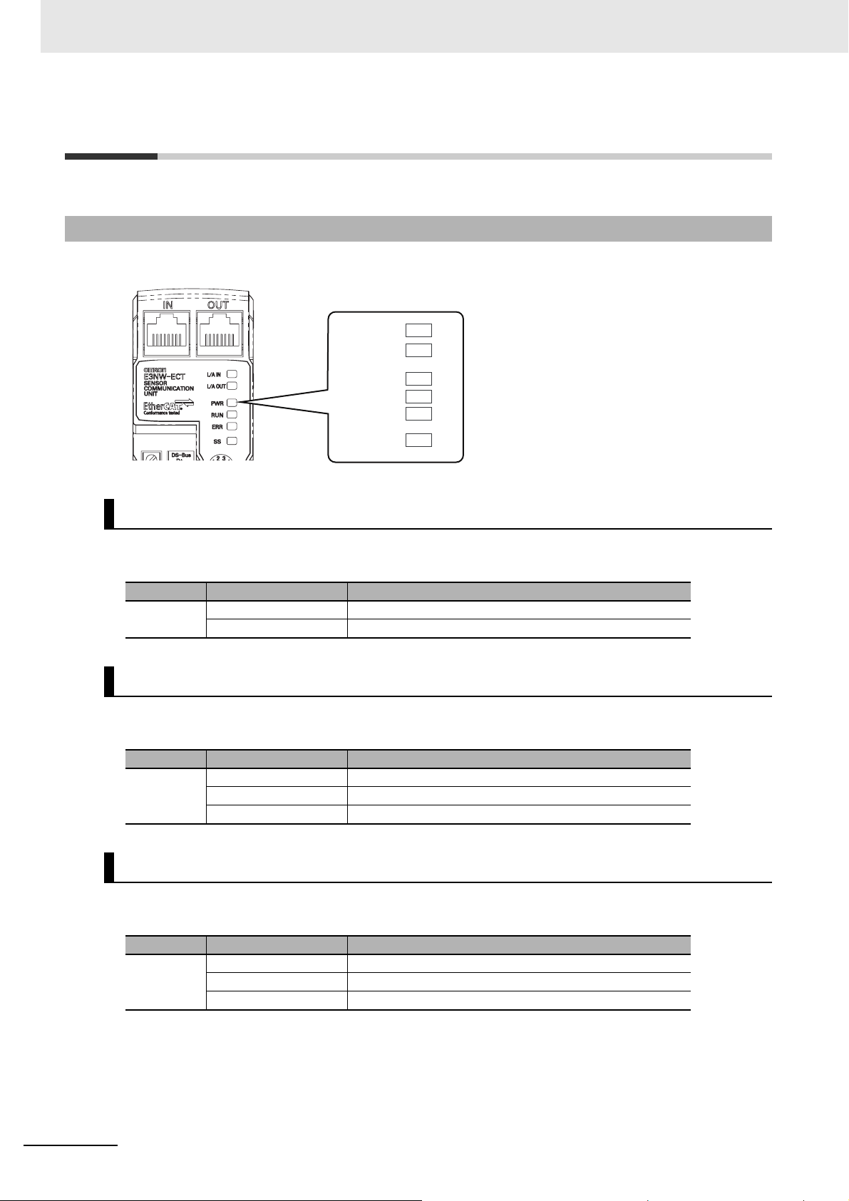
6 Hardware Specifications of E3NW-ECT
PWR
L/A IN
L/A OUT
RUN
ERR
SS
6-3 Hardware Specifications
6-3-1 Status Indicators
It indicates the current state of an EtherCAT Slave Unit.
[PWR] indicator
Indicates the unit power supply state.
Color State Contents
Green
OFF Unit power OFF state
ON The unit power (24 VDC) is supplied to the Slave Unit.
[L/A IN] indicator
Indicates the communication state (input side).
Color State Contents
OFF Link not established in physical layer
Green
Flickering In operation after establishing link
ON Link established in physical layer
[L/A OUT] indicator
Indicates the communication state (output side).
6 - 4
Color State Contents
OFF Link not established in physical layer
Green
Flickering In operation after establishing link
ON Link established in physical layer
E3NW-ECT EtherCAT Digital Sensor Communication Unit Operation Manual (E429)
Page 67
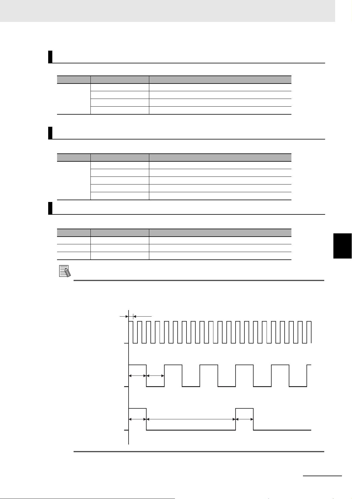
6 Hardware Specifications of E3NW-ECT
Reference
[RUN] indicator
It indicates the operation state.
Color State Contents
OFF Init state
Green
Blinking Pre-Operational state
Single flash Safe-Operational state
ON Operational state
For details on each state, refer to "5-3 Communications State Transitions" on page 5-4.
[ERR] indicator
It indicates the information of an error.
Color State Contents
OFF No error
Blinking Communications setting error
Red
Single flash Synchronization error or communications data error
Flickering Boot error
ON PDI WDT timeout
6-3 Hardware Specifications
[SS] indicator
It indicates the information of an Sensor Status.
Color State Contents
OFF Power OFF or Initial status of sensor connection
Green ON Normal
Red ON Sensor Error: Connecting Sensors is different form setting.
The timing of each flashing state of indicator is as follows.
50 ms
on
Flickering
off
on
Blinking
200 ms 200 ms
off
6
6-3-1 Status Indicators
on
1000 ms
Single flash
200 ms 200 ms
off
E3NW-ECT EtherCAT Digital Sensor Communication Unit Operation Manual (E429)
6 - 5
Page 68

6 Hardware Specifications of E3NW-ECT
Precautions for Correct Use
Setting the node address (×10)
Setting the node address (×1)
Setting the node address (×100)
6-3-2 Node Address Setting Switches
These switches are used to set node addresse s of Slav e Units in the EtherC AT network (decimal).
Set the node address switches as follows: Top switch for the 100s digit, middle switch for the 10s digit,
and the bottom switch for the 1s digit.
Setting range is 000 to 997. (Default setting: 000)
Note that the node address set values vary as shown below when the EtherCAT Master Unit is made by
OMRON or by other manufacturers.
Node address
switch setting
000
001 to 997
(Notes) The system will not operate correctly if the node address switches are set to 998 or 999.
OMRON EtherCAT Master Unit
NJ01-100 or CJ1W-NC82
The node address can be set within the
following range with the Configuration
Tool.
NJ01-100: 001 to 192
CJ1W-NE82: 001 to 077
The value that is set on the node
address switches is used as the node
address.
The valid setting ranges are as follows:
NJ01-100: 001 to 192
CJ1W-NE82: 001 to 077
Set value for node address
EtherCAT Master Unit from another
manufacturer
Setting with the Configuration Tool
(The switch setting has no effect.)
• The setting on the node address switches is read only once when the power is turned ON.
Even if the settings are changed after turning the power supply ON, they are not reflected in
the control. They become effective when the power supply is turned ON the next time.
• If node addresses overlap, an error occur s an d th e op er a tion st o ps.
6 - 6
E3NW-ECT EtherCAT Digital Sensor Communication Unit Operation Manual (E429)
Page 69

6-3-3 Communications Connectors
18
−Vterminal
+Vterminal
Name
Specification
+V
−V
24 VDC
0 VDC
Fixing
Screw
The Connectors are used to connect the communications cables.
The specifications are shown below.
6 Hardware Specifications of E3NW-ECT
6-3 Hardware Specifications
• Electrical characteristics: Conforms to the IEEE 802.3u standard.
• Connector structure: RJ45 8-pin modular connector (conforms to ISO 8877)
• Terminal arrangement
Pin No. Signal name Abbreviation
1 Send data + TD +
2 Send data − TD −
3 Receive data + RD +
4 Not used −
5 Not used −
6 Receive data − RD −
7 Not used −
8 Not used −
Hood Frame ground FG
6-3-4 Unit Power Supply Connector
The Connector is used to connect the unit power supply (24 VDC).
6
6-3-3 Communications Connectors
• Connector type: Spring connection connector with fixing screw (2-pin)
2
• Supported pin terminal diameter: 0.25 mm
to 0.5 mm2/AWG24 to AWG20
(Pin terminal with isolation sleeve used)
For types of recommended pin terminals, refer to "4-3-3 Connecting the Unit Power Supply" on page
4-9.
E3NW-ECT EtherCAT Digital Sensor Communication Unit Operation Manual (E429)
6 - 7
Page 70

6 Hardware Specifications of E3NW-ECT
6 - 8
E3NW-ECT EtherCAT Digital Sensor Communication Unit Operation Manual (E429)
Page 71

Function Specifications
This chapter explains the function specifications of E3NW-ECT.
7-1 I/O Data Allocation (PDO Mapping) . . . . . . . . . . . . . . . . . . . . . . . . . . . . . . . 7-2
7-1-1 Input Data Allocation . . . . . . . . . . . . . . . . . . . . . . . . . . . . . . . . . . . . . . . . . . . . . 7-2
7-2 Functions of E3NW-ECT . . . . . . . . . . . . . . . . . . . . . . . . . . . . . . . . . . . . . . . . 7-5
7-2-1 Input Filter . . . . . . . . . . . . . . . . . . . . . . . . . . . . . . . . . . . . . . . . . . . . . . . . . . . . . 7-5
7-2-2 Dummy Sensor Setting . . . . . . . . . . . . . . . . . . . . . . . . . . . . . . . . . . . . . . . . . . . 7-6
7-2-3 Mode Setting Functions for PDO Com mu ni c a ti o ns . . . . . . . . . . . . . . . . . . . . . 7-6
7-2-4 Automatic Detection of Connected Sensor Amplifiers . . . . . . . . . . . . . . . . . . . 7-8
7-3 Mounting Dimensions . . . . . . . . . . . . . . . . . . . . . . . . . . . . . . . . . . . . . . . . . . 7-9
7
E3NW-ECT EtherCAT Digital Sensor Communication Unit Operation Manual (E429)
7 - 1
Page 72

7 Function Specifications
Unit numbers are assigned in order
from 1 going from left to right.
Amplifier Units
Sensor Communication
Unit
Distributed
Sensor Unit 1
Distributed
Sensor Unit 2
DIN Track
Sensor Heads
Connectors
Unit 1
Unit 2
Unit 3
Unit 4
Unit 5
Unit 6
Unit 7
Unit 8
Unit 9
Unit 10
Unit 11
Unit 12
Unit 13
Unit 14
Unit 15
Unit 16
Unit 17
Unit 18
Unit 19
Unit 20
Unit 21
Unit 22
7-1 I/O Data Allocation (PDO Mapping)
I/O data of Digital I/O Slave Units are allocated to the input/output areas of the I/O memory of the
EtherCAT Master Unit, respectively. For the detailed explanation of allocation method, refer to the
manual of EtherCAT Master Unit to be connected.
7-1-1 Input Data Allocation
Sensor Numbers
7 - 2
The Sensor Communication Unit identifies each connected Sensor Amplifier by its unit number. The
unit numbers for the Sensors are numbered in order starting from 1. Each Sensor Amplifier that is
assigned a unit number has an input 1 (Sensor output 1) and input 2 (Sensor output 2). The unit
numbers of the Sensor Amplifiers that are connected to a Distributed Sensor Unit are numbered
sequentially, in the order shown below, following the unit numbers of the Sensor Amplifiers that are
connected to the Sensor Communicatio n Unit.
E3NW-ECT EtherCAT Digital Sensor Communication Unit Operation Manual (E429)
Page 73

7 Function Specifications
Sensor Communication Unit -> Distributed Sensor Unit 1 -> Distributed Sensor Unit 2 -> ... ->
Distributed Sensor Unit 8
Y ou can connect a maximum of 30 Sensor Amplifiers. (Refer to "2-2-2 Number of Connected Sensor
Amplifiers" on page 2-3.)
You can connect a maximum of eight Distributed Sensor Units to the E3NW-ECT.
Input data allocation example
The following table lists the items that you can assign to the E3NW-ECT.
You can assign a maximum of 350 bytes of PDOs. (Refer to "7-2-3 Mode Setting Functions for PDO
Communications" on page 7-6.) Refer to "A- 1-5 PDO Mapping O bject" on page A-7 for detailed object
specifications.
Refer to the specific manual for your master for information on changing the PDO mappings.
Transmit
Index
1B00 hex 257th
1B01 hex 258th
1B02 hex 259th
1B03 hex 260th
1B04 hex 261st
1B05 hex 262nd
1
B06 hex 263rd
1B07 hex 264th
1B08 hex 265th
1B09 hex 266th
1B0A hex 267th Number of Sensors Setting
1B0B hex 268th
1B0D hex 270th
1B10 hex
1B12 hex
· · ·
1B48 hex
1B4C hex
1B4D hex
1B4E hex
· · ·
1BA5 hex
PDO
mapping
273rd
274th
· · ·
332nd
333rd
334th
335th
· · ·
422nd
Name Size Applicable Sensor Amplifier Units
Read input 1st Word (Bits 00 to 15)
Read input 2nd Word (Bits 16 to 31)
Read input 3rd Word (Bits 32 to 47)
Read input 4th Word (Bits 48 to 59)
Read input bits (Bits 00 to 15)
Read input bits (Bits 16 to 31)
Read inp
Read input bits (Bits 48 to 59)
Sensor Communications Status
8-bit Sensor Communications Status
Number of Sensors with Dummy
Sensor Warning Status
Sensor Warning Status 1 to 16
Unit 01 Detection Level of Input 1
Unit 01 Detection Level of Input 2
· · ·
Unit 30 Detection Level of Input 2
Unit 01 Threshold 1 Settings of Input 1
Unit 01 Threshold 2 Settings of Input 1
Unit 01 Threshold 1 Settings of Input 2
· · ·
Unit 30 Threshold 1 Settings of Input 2
ut bits (Bits 32 to 47)
U16 FA0
MA0
U16 FA0
MA0
U16 FA0
MA0
U16 FA0
MA0
U16 FA0
MA0
U16 FA0
MA0
U16 FA0
MA0
U16 FA0
MA0
U8 FA0
MA0
U8 FA0
MA0
U16 FA0
MA0
U32 FA0
MA0
U16 FA0
MA0
INT16 FA0
MA0
INT32 FA0
MA0
LA0
FAH0
LA0
FAH0
LA0
FAH0
LA0
FAH0
LA0
FAH0
LA0
FAH0
LA0
FAH0
LA0
FAH0
LA0
FAH0
LA0
FAH0
LA0
FAH0
LA0
FA
H0
LA0
FAH0
LA0
FAH0
LA0
FAH0
SA0
EA□0
SA0
EA□0
SA0
EA□0
SA0
EA□0
SA0
EA□0
SA0
EA□0
SA0
EA□0
SA0
EA□0
SA0
EA□0
SA0
EA□0
SA0
EA□0
SA0
EA□0
SA0
EA□0
SA0
EA□0--
SA0
EA□0
TA0
AA□0
TA0
AA□0
TA0
AA□0
TA0
AA□0
TA0
AA□0
TA0
AA□0
TA0
AA□0
TA0
AA□0
TA0
AA□0
TA0
AA□0
TA0
AA□0
TA0
AA□0
TA0
AA□0
TA0
AA□0
CA0
VA□0
CA0
VA□0
CA0
VA□0
CA0
VA□0
CA0
VA□0
CA0
VA□0
CA0
VA□0
CA0
VA□0
CA0
VA□0
CA0
VA□0
CA0
VA□0
CA0
VA□0
CA0
VA□0
CA0
-
CA0
VA□0
7-1 I/O Data Allocation (PDO Mapping)
7
7-1-1 Input Data Allocation
E3NW-ECT EtherCAT Digital Sensor Communication Unit Operation Manual (E429)
7 - 3
Page 74

7 Function Specifications
Transmit
Index
1BA6 hex
1BA7 hex
· · ·
1BC3 hex
1BFF hex 512nd
* The E9NC-TA0 is supported from E3NW-ECT Ver 1.03. The E3NX-CA0 is supported from E3NW-ECT Ver 1.06.
E3NX-MA0, E2NC-EA□0, and E9NC-AA□0 / VA□0 are supported from Version 1.08 of the E3NW-ECT.
You can check the version with object index 100A hex. (Refer to "A-1-4 Communication Objects" on page A-4.)
PDO
mapping
423rd
424th
· · ·
452nd
Name Size Applicable Sensor Amplifier Units
Unit 01 Detection Levels (4 bytes)
Unit 02 Detection Levels (4 bytes)
· · ·
Unit 30 Detection Levels (4 bytes)
Sysmac Error Status
INT32 -
U8 FA0
MA0
-
-
-
LA0
FAH0
-
-
SA0
EA□0
TA0
AA□0-VA□0
TA0
AA□0
CA0
VA□0
7 - 4
E3NW-ECT EtherCAT Digital Sensor Communication Unit Operation Manual (E429)
Page 75

7-2 Functions of E3NW-ECT
1234
ON
ON ON
OFF
OFF OFF
ON
OFF
Data set to be input
Input data is OFF because all data
is not ON during 4 readings.
ON
OFF
OFF
ON
1
23
4
ON ON ON ON
Data set to be input
ON delay time
Input data is ON because all data
is ON during 4 readings.
Digital I/O Slave Units have the following convenient functions, in addition to the I/O signal processing.
7-2-1 Input Filter
Overview of functions
Purpose
This function prevents data changes and unstable data, which may be caused by fluctuation of input
data and unstable contact state due to chattering and noise. This function is available in Free Run
Mode.
7 Function Specifications
Details of functions
This function reads inputs (ON/OFF) within a certain set time and turn ON the inputs if they are all
same (all ON or all OFF)
Note that this function works for all inputs of Slave Units and Expansion Units at the same time.
When the input shifts from OFF to ON (or ON to OFF), it is read 4 times from that point at an interval
of 1/4 of the set time. When all read results are ON (or OFF), the input is turned ON (or OFF).
, and turn them OFF if not.
7-2 Functions of E3NW-ECT
7
7-2-1 Input Filter
Setting method
The input filter is set through SDO communications.
The applicable index is 3002 hex.
Refer to the applicable index (Input Filter in Free-Run Mode) in "A-1 Object Dictionary" on page A-2 for
the set values.
E3NW-ECT EtherCAT Digital Sensor Communication Unit Operation Manual (E429)
7 - 5
Page 76

7 Function Specifications
7-2-2 Dummy Sensor Setting
Overview of functions
Purpose
This function provides keeping I/O map, when number of sensor change by customer option,
sensing point degrees and so on.
Details of functions
E3NW-ECT can be set dummy sensor, so I/O map keep by using dummy sensor setting.
Setting method
The settings are made using the SDO communication.
The target index is 3004 hex.
For the set values, refer to the description of object index 3004 hex (Dummy Setting Object) in "A-1
Object Dictionary" on page A-2.
7-2-3 Mode Setting Functions for PDO Communications
Outline of Operation
Application
There are two modes for data refreshing with PDO communications. Select the mode based on the
number of input data to assign for PDO communications and the refresh cycle.
* In this section, the refresh cycle applies to data in the Sensor Communication Unit. This is not the refresh
cycle for data between the Sensor Communication Unit and the master.
• Normal Mode
In Normal Mode, the assigned inputs may not be refreshed every cycle, but you can assign a
large amount of input data.
• Detection Level Speed Priority Mode
With this mode, you can assign less input data than with Normal Mode, but the assigned data,
such as the detection levels, are refreshed every cycle.
In either mode, I/O data are refreshed every cycle.
*
7 - 6
E3NW-ECT EtherCAT Digital Sensor Communication Unit Operation Manual (E429)
Page 77

7 Function Specifications
Details of Functions
• Normal Mode
This mode allows you to assign up to 350 bytes of input data.
The assigned input data (except for I/O dat a) are divided and refre shed in order across mor e than
one cycle.
• Detection Level Speed Priority Mode
This mode allows you to assign up to 108 bytes of input data.
All assigned input data are refreshed every cycle.
The refresh cycle depends on the number of Sensors, amount of assigned data, and whether
input filters and Dummy Sensors are used.
The refresh cycle for data in the Sensor Communications Unit for each mode is given in the
following table.
• Free-Run Mode
Mode Norma l Mode Detection Level Speed Priority Mode
Number of Sensors 30 ma x. 16 max. 30 max. 30 max. 30 max.
Assigned data size
[bytes]
Input filter With or without None
Dummy Sensors With or without None
Refresh cycle [μs] 200 100 125 150 175
350 16 max. 36 max. 37 to 76 77 to 108
With or
without
With or
without
With or
without
With or
without
With or
without
With or
without
7-2 Functions of E3NW-ECT
• DC Mode
The refresh cycle is the same as the output cycle of the Sync0 signal.
Setting Methods
The PDO communications mode is set through SDO communications.
The applicable index is 300C hex.
For the set values, refer to the description of object index 300C hex (TxPDO Mapping Mode) in "A-1
Object Dictionary" on page A-2.
7
7-2-3 Mode Setting Functions for PDO Communications
E3NW-ECT EtherCAT Digital Sensor Communication Unit Operation Manual (E429)
7 - 7
Page 78

7 Function Specifications
Precautions for Correct Use
7-2-4 Automatic Detection of Connected Sensor Amplifiers
Outline of Operation
Application
The Sensor Communication Unit and the Distributed Sensor Unit have a feature that automatically
registers the number of connected Sensor Amplifiers. It is not necessary to register the number of
Sensor Amplifiers with the Configuration Tool or through SDO communications in advance. (Y ou can
also manually register the number of Sensor Amplifiers with the Configuration Tool or through SDO
communications.)
Details of Functions
The Sensor Communication Unit and Distributed Sensor Unit detect the number of Sensor
Amplifiers that are connected to them when the power supply is turned ON. This number is
registered as the number of Sensor Amplifiers. It does not matter whether you turn ON the power
supply to the Sensor Communication Unit or to the Distributed Sensor Units first.
If the number of Sensor Amplifiers that are connected to the Sensor Communication Unit and
Distributed Sensor Units changes after the power su pply is turned ON (i.e., if the register ed number
disagrees with the connected number), an error occurs. Refer to Chapter 8 Troubleshooting and
Maintenance for details.
If you need to add Sensor Amplifiers to the Sensor Communication Unit or to a Distributed
Sensor Unit after the system begins operation, make sure to turn OFF the power supply to the
Sensor Communication Unit and all Distributed Sensor Units.
Setting Methods
To manually register the number of Sensor Amplifiers, use SDO communications.
The applicable index is 3001 hex.
For the set values, refer to the description of object index 3001 hex (Number of Sensors) in "A-1 Object
Dictionary" on page A-2.
7 - 8
E3NW-ECT EtherCAT Digital Sensor Communication Unit Operation Manual (E429)
Page 79

7-3 Mounting Dimensions
E3NW-ECT
Power Connector (Accessories)
(FK-MCP 1,5/2-STF-3,5 AU)
Communication Connector
(IN)
Communication Connector
(OUT)
Connector Cover
Communication
Connector (Accessories)
(FK-MCP 1,5/2-STF-3,5 AU)
(4.2)
DIN RAIL (OPTION)
(PFP-N)
(28.6)
38.8
(43)
41
18
46.6
64.5
86.6
15.4
60.9
10
10
102.5
105.1
13.5
9.5
32.5
13.1
(36.7)
93.8
32.2
(35)
36.7
(49.8)
52.7
19.5
E3NW-DS
0.6
0.2
13.1
Cap and connector
Connector (provided)
(FK-MCP 1,5/4-STF-3,5 AU)
49
69
86.9
34.3
25.4
42.9
52.8
36.7
(35)
(44.5)
PFP-N DIN Track
(sold separately)
The mounting dimensions are shown below.
7 Function Specifications
7-3 Mounting Dimensions
7
E3NW-ECT EtherCAT Digital Sensor Communication Unit Operation Manual (E429)
7 - 9
Page 80

7 Function Specifications
5.1
3.4
33.5
(37.9)
90.8
(39.5)
(29.9)
26
Optical communications
PFP-N DIN Track
(sold separately)
10
10
5.7
4.5
13.8
11.5
ST indicator
Incident level (white, digital)
OUT1 selection indicator
Threshold level (green, digital)
OUT1 indicator
OUT2 indicator
OUT2 selection indicator
L/D indicator
DCP indicator
(16.5)
20.5
140
(max. value with cover open)
152°
(max. value with cover open)
104.8
Two, 2.4 dia.
holes
With Fiber Attachment
(E39-F9) attached
(37)
Mounted to DIN Track
E3NX-FA0
(max. value with
cover open)
27.8
21
DCP indicator
ST indicator
Incident level
(white, digital)
Threshold level (green, digital)
OUT2 indicator
OUT2 selection indicator
OUT1 selection indicator
OUT1 indicator
(max. value
with cover
open)
159.7 (max. value with cover open)
Optical communications
L/D indicator
Mounted to DIN Track
PFP-N DIN Track
(sold separately)
E3NC-LA0
(max. value with cover open)
152°
102.4
2.6
30.2
27.8
114
10
11.5
13.8
(37)
33.5
(39.5)
(49.5)
32.1
26
(29.9)
7 - 10
E3NW-ECT EtherCAT Digital Sensor Communication Unit Operation Manual (E429)
Page 81
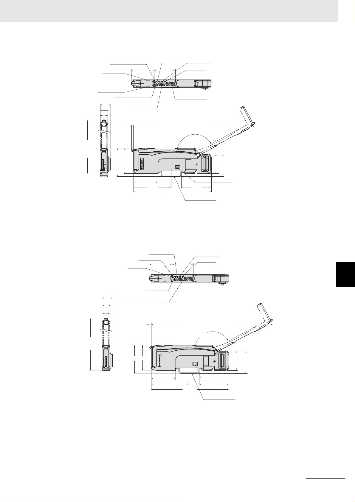
7 Function Specifications
152° (max. value with cover open)
Optical communications
L/D indicator
ZERO indicator
ST indicator
Measurement value
(white, digital)
Threshold level
(green, digital)
OUT2 indicator
OUT1 selection indicator
OUT1 indicator
OUT2 selection indicator
159.7 (max. value with cover open)
PFP-N DIN Track
(sold separately)
Mounted to DIN Track
E3NC-SA0
(max. value
with cover
open)
2.6
10
11.5
13.8
27.8
114
(37)
33.5
30.2
102.4
(39.5)(49.5)
32.1
26
(29.9)
102.4
33.5
159.7
10
114
E9NC-TA0
114
(max. value
with cover open)
GO indicator
13.8
11. 5
Measurement data display
(white, digital)
10
(37)
NO/NC indicator
HIGH indicator
30.2
LOW indicator
2.6
33.5
32.1
(49.5)
PRST indicator
27.8
ST indicator
Mounted to DIN Track
159.7
(max. value with cover open)
152° (max. value with cover open)
Optical communications
102.4
(39.3)
PFP-N DIN Track
(sold separately)
7-3 Mounting Dimensions
7
26
(29.9)
E3NW-ECT EtherCAT Digital Sensor Communication Unit Operation Manual (E429)
7 - 11
Page 82

7 Function Specifications
5.1
3.4
33.5
(37.9)
90.8
(39.5)
(29.9)
26
Optical communications
PFP-N DIN Track
(sold separately)
10
10
5.7
4.5
13.8
11.5
Incident level (white, digital)
OUT1 selection indicator
Threshold level (green, digital)
OUT1 indicator
OUT2 indicator
OUT2 selection indicator
(16.5)
20.5
140
(max. value with cover open)
152°
(max. value with cover open)
104.8
Two, 2.4 dia.
holes
With Fiber Attachment
(E39-F9) attached
(37)
Mounted to DIN Track
E3NX-CA0
(max. value with
cover open)
27.8
21
NO/NC indicator light
ST indicator light
E3NX-MA0
E3NX-FAH0
* It is the same as E3NX-FA0
7 - 12
E3NW-ECT EtherCAT Digital Sensor Communication Unit Operation Manual (E429)
Page 83

E2NC-EA□0
7 Function Specifications
E9NC-AA□0 / VA□0
7-3 Mounting Dimensions
7
E3NW-ECT EtherCAT Digital Sensor Communication Unit Operation Manual (E429)
7 - 13
Page 84

7 Function Specifications
7 - 14
E3NW-ECT EtherCAT Digital Sensor Communication Unit Operation Manual (E429)
Page 85

Troubleshooting and Maintenance
This chapter explains actions to be taken at errors, troubleshooting, and equipment
maintenance.
8-1 Troubleshooting . . . . . . . . . . . . . . . . . . . . . . . . . . . . . . . . . . . . . . . . . . . . . . . 8-2
8-1-1 Errors that Can be Checked with Status Indicator and Actions to Take . . . . . . 8-2
8-1-2 Errors Unique to E3NW-ECT . . . . . . . . . . . . . . . . . . . . . . . . . . . . . . . . . . . . . . 8-6
8-1-3 Error Notification Methods and Types . . . . . . . . . . . . . . . . . . . . . . . . . . . . . . . . 8-7
8-1-4 Sysmac Error Status Codes . . . . . . . . . . . . . . . . . . . . . . . . . . . . . . . . . . . . . . . 8-8
8-1-5 Emergency Error Code . . . . . . . . . . . . . . . . . . . . . . . . . . . . . . . . . . . . . . . . . . 8-15
8-1-6 Application Layer Status Codes . . . . . . . . . . . . . . . . . . . . . . . . . . . . . . . . . . . 8-16
8-2 Equipment Maintenance . . . . . . . . . . . . . . . . . . . . . . . . . . . . . . . . . . . . . . . 8-18
8-2-1 Cleaning . . . . . . . . . . . . . . . . . . . . . . . . . . . . . . . . . . . . . . . . . . . . . . . . . . . . . 8-18
8-2-2 Inspections . . . . . . . . . . . . . . . . . . . . . . . . . . . . . . . . . . . . . . . . . . . . . . . . . . . 8-18
8-2-3 Handling when Replacing Units . . . . . . . . . . . . . . . . . . . . . . . . . . . . . . . . . . . 8-19
8
E3NW-ECT EtherCAT Digital Sensor Communication Unit Operation Manual (E429)
8 - 1
Page 86

8 Troubleshooting and Maintenance
8-1 Troubleshooting
8-1-1 Errors that Can be Checked with Status Indicator and Actions to
Take
Errors can be notified by status indicators on Slave Units.
In this section, the states of status indicator are indicated using the following abbreviations.
Abbreviation Definition
On ON
Off OFF
F Flickering (ON (50 ms) - OFF (50 ms) flashing)
B Blinking (ON (200 ms) - OFF (200 ms) flashing)
SF Single flash (ON (200 ms) - OFF (1000 ms) flashing)
− Unknown
For details on definition of each state, refer to "6-3-1 Status Indicators" on page 6-4.
Errors of Slave Unit
[PWR]
indicator
On F On Off
Off Off Off Off
[L/A IN]
[L/A OUT]
LED
[RUN]
indicator
[ERR]
indicator
Description Cause Actions
PDO communications
EtherCAT
communication
is in progress.
Power supply
error
−
The power is not
properly supplied
to the Slave Unit.
or both PDO and SDO
communications are
being executed.
Stat e is no rmal.
After removing the
following factors of
power supply shutdown,
restart the Slave Unit
according to the
specification of
connected EtherCAT
Master Unit.
• Are the power supply
cables wired
correctly?
• Are the power supply
cables disconnected?
• Is the power supply
voltage within the
specification range?
• Is the power supply
capacity sufficient?
• Is the power supply
malfunctioning?
8 - 2
E3NW-ECT EtherCAT Digital Sensor Communication Unit Operation Manual (E429)
Page 87

8 Troubleshooting and Maintenance
[PWR]
indicator
On − Off
On −−B
[L/A IN]
[L/A OUT]
LED
[RUN]
indicator
[ERR]
indicator
On
F
Description Cause Actions
If the error does not
clear even after the
Hardware error
Illegal switch
setting
Non-volatile
memory data
error
Sync manager
setting error
Hardware error
A hardware failure
occurred.
A range setting
switch or other
switch setting is
illegal.
A non-volatile
memory data error
occurred.
The sync manager
setting is illegal.
A hardware failure
occurred.
power is turned ON
again, the Slave Unit
hardware is damaged.
Replace the Slave Unit.
Check the switch
settings then restart the
Slave Unit according to
the specification of
connected EtherCAT
Master Unit.
Use the Configuration
Tool or SDO
communications to
restore the default data
and restart the Slave
Unit according to the
specification of
connected EtherCAT
Master Unit.
Change to the correct
settings.
If the problem is not
resolved even after the
measures described
above are taken, the
Slave Unit hardware
may be damaged.
Replace the applicable
Slave Unit.
8-1 Troubleshooting
8
Actions to Take
8-1-1 Errors that Can be Checked with Status Indicator and
E3NW-ECT EtherCAT Digital Sensor Communication Unit Operation Manual (E429)
8 - 3
Page 88

8 Troubleshooting and Maintenance
Errors of EtherCAT Network
[PWR]
indicator
On On −−
On Off −−
[L/A IN]
[L/A OUT]
LED
[RUN]
indicator
[ERR]
indicator
Description Cause Actions
Link
established in
physical layer
Link not
established in
physical layer
Operation standby
status after
establishing link in
physical layer.
A link in physical
layer has not been
established.
The host master
has not been
started.
A hardware failure
occurred.
−
After checking the
following items, restart
the Slave Unit according
to the specification of
connected EtherCAT
Master Unit.
• Is the
communications
cable wired correctly?
• Are any cables
disconnected or loose
in the part that
connects to the
connector?
• Is the cable length
appropriate?
• Is the
communications
cable of the
recommended
specification?
Check that EtherCAT
Master Unit is operating
correctly . If using an
OMRON EtherCAT
Master Unit, check the
EtherCAT Master Unit
mode and Slave Unit
node addresses. If
using EtherCAT Master
Unit from another
manufacturer, refer to
the user's manual for
that Master Unit.
If the problem is not
resolved even after the
measures described
above are taken, the
Slave Unit hardware
may be damaged.
Replace the applicable
Slave Unit.
8 - 4
E3NW-ECT EtherCAT Digital Sensor Communication Unit Operation Manual (E429)
Page 89

8 Troubleshooting and Maintenance
[PWR]
indicator
On − SF −
On − B −
On − Off − Init state
* Due to the EtherCAT specification, a communication timeout does not occur with those Slave Units that only
handle input data.
[L/A IN]
[L/A OUT]
LED
[RUN]
indicator
[ERR]
indicator
Description Cause Actions
It is commanded
SafeOperational
state
PreOperational
state
from the EtherCAT
Master Unit to shift
to the
Safe-Operational
state.
It is commanded
from the EtherCAT
Master Unit to shift
to the
Pre-Operational
state.
It is commanded
from the EtherCAT
Master Unit to shift
to the Init state.
If the trouble occurred
during operating the
system, check the state
of the connected
EtherCAT Master Unit.
Synchronization Errors
[PWR]
indicator
On − BB
On − BSF
On − SF SF
[L/A IN]
[L/A OUT]
LED
[RUN]
indicator
[ERR]
indicator
Description Actions
After checking the following items,
Synchronization
frequency (Sync0
frequency) setting error
Synchronization error (at
synchronization start)
Communications
synchronization error
restart the Slave Unit according to
the specification of connected
EtherCAT Master Unit.
• Set the correct synchronization
frequency.
After checking the following items,
restart the Slave Unit according to
the specification of connected
EtherCAT Master Unit.
• Is the communications cable
wired correctly?
• Is the communications cable
exposed to excessive noise?
• Review set time of Sync Not
Received Timeout Setting
(synchronization error setting).
After checking the following items,
restart the Slave Unit according to
the specification of connected
EtherCAT Master Unit.
• Is the communications cable
wired correctly?
• Is the communications cable
exposed to excessive noise?
• Review set time of
Communication Error Setting .
8
Actions to Take
8-1 Troubleshooting
8-1-1 Errors that Can be Checked with Status Indicator and
E3NW-ECT EtherCAT Digital Sensor Communication Unit Operation Manual (E429)
8 - 5
Page 90

8 Troubleshooting and Maintenance
[PWR]
indicator
On − SF SF
[L/A IN]
[L/A OUT]
LED
[RUN]
indicator
[ERR]
indicator
8-1-2 Errors Unique to E3NW-ECT
Symptom Cause Measures
Some functions are not reflected
even after parameters have been
set.
The Sensor Amplifier is turned ON
but there is no input.
SS LED lights red
The functions enabled by recycling
the power were changed.
There is a communications error.
The SS indicator is lit red. See below.
Number of sensors setting is
different from Number of
connecting sensors
Description Actions
After checking the following items,
restart the Slave Unit according to
the specification of connected
EtherCAT Master Unit.
Synchronization error (in
operation)
• Is the communications cable
wired correctly?
• Is the communications cable
exposed to excessive noise?
If this does not improve, the Slave
Unit hardware may be damaged.
Replace the applicable Slave Unit.
Turn ON Slave Unit power supply
again after changing the setting.
Check the connected number of
sensors.
Check the connected number of
sensors.
When use dummy sensor setting,
Set number of sensors setting as
include dummy sensors.
Amplifier connecting is wrong,
Check the connecting of
E3NW-ECT and amplifiers.
The connected Sensor Amplifier
Units failed. Replace with the Units.
There is an error in the connections
to the Distributed Sensor Unit.
Check the installation procedure
for the Distributed Sensor Unit.
8 - 6
E3NW-ECT EtherCAT Digital Sensor Communication Unit Operation Manual (E429)
Page 91
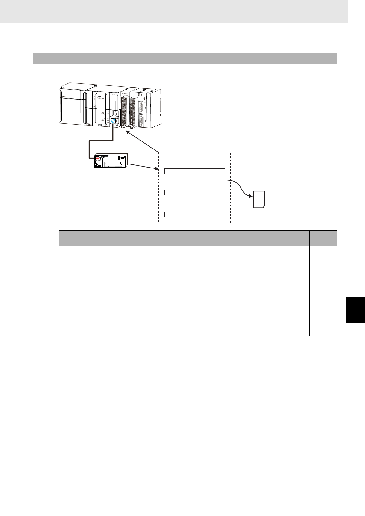
8 Troubleshooting and Maintenance
Emergency message
Sysmac error status
Application layer status
Error occurs.
Master notified.
Diagnosis
history
ID211
0
1
3
2
4
5
7
6
8
9
11
10
12
13
14
15
DC24V
7mA
COM
MACH
No
.
AD042
RUN
ERC
ERH
B1 A1
x10
1
x10
0
0
9
8
7
6
5
4
3
2
1
0
9
8
7
6
5
4
3
2
1
01234567
8
9
10 11 12 13 14 15
EtherCAT Slave Unit
EtherCAT Master Unit
8-1-3 Error Notification Methods and Types
This section describes the notification methods for errors that occur in the Slave Units.
Error notification
type
Sysmac error
status
Emergency
messages
Application layer
status
Description Notification method Page
Notification is provided when an erro r is
detected in the application. These errors
are displayed only on the OMRON Sysmac
Studio Support Software.
Notification is provided of application-level
errors. Either CiA-defined error codes are
used or error codes are added to
vendor-specific areas.
Notification is provided of errors in
EtherCAT communications. The error
notification method and error codes that are
defined by ETG are used.
Error status is received by the
TxPDO and the master is notified
of errors every cycle.
The slave notifies the master
when an error occurs.
The master is notified by writing
to the application layer status
register when an error occurs.
8-1 Troubleshooting
8-8
8-15
8
8-16
8-1-3 Error Notification Methods and Types
E3NW-ECT EtherCAT Digital Sensor Communication Unit Operation Manual (E429)
8 - 7
Page 92

8 Troubleshooting and Maintenance
8-1-4 Sysmac Error Status Codes
A table that describes the error event codes that are displayed on the Sysmac Studio is given below.
Error List
The errors (i.e., events) that can occur in the E3NW-ECT EtherCAT Slave Unit are given on
the following pages. Event levels are given as following in the ta bles:
Maj: Major fault level
Prt: Partial fault level
Min: Minor fault level
Obs: Observation
Info: Information
Refer to the NJ-series Troubleshooting Manual (Cat. No. W503) for all of the event codes that may
occur in an NJ-series Controller.
Event code Event name Meaning Assumed cause
04C40000 hex Sensor Com-
munications
Error
04C50000 hex Sensor Com-
munications
Has Not
Been Established
14A00000 hex Non-volatile
Memory
Checksum
Error
247A0000hex Number of
Distributed
Sensor Unit
Verify Error
247B0000hex Number of
Sensors
Over Limit
247C0000hex Number of
Sensors Verify Error
247D0000hex Number of
Sensors
Over at Distributed Sensor Unit
34F80000 hex Dummy Sen-
sors Setting
Error
04A10000 hex Non-volatile
Memory
Hardware
Error
An error occurred in
a Sensor connection.
Communications
has not been established with the Sensor.
An error occurred in
the control parameters.
The number of Distributed Sensor Unit
that is checked at
power up is
decreased.
Too many Sensors
are connected.
The number of Sensors that is connected does not
agree with the settings.
Too many Sensors
are connected at
Distributed Sensor
Unit.
Too many Dummy
Units are set.
An error occurred in
non-volatile memory.
• The Sensor is disconnected. √ 8-10
• A sensor is not connected. √ 8-10
• Noise √ 8-11
• The Distributed Sensor Unit is
disconnected
• More than the maximum number of Sensors are connected.
• The set value does not match
the number of Sensors that are
actually connected
• More than the maximum number of Sensors are connected
at Distributed Sensor Unit.
• There are too many Dummy
Units set, so some Sensors are
not assigned logical unit numbers.
• Non-volatile memory failure √ 8-14
Level
Maj Prt Min Obs Info
√ 8-11
√ 8-12
√ 8-12
√ 8-13
√ 8-13
Reference
8 - 8
E3NW-ECT EtherCAT Digital Sensor Communication Unit Operation Manual (E429)
Page 93

8 Troubleshooting and Maintenance
Error Description
This section describes the information that is given for individual errors.
Controller Error Descriptions
The items that are used to describe individual errors (events) are described in the following copy of
an error table.
Event name Gives the name of the error (event). Event code Gives the code of the error (event).
Meaning Gives a short description of the error (event).
Source Gives the source of the error (event). Source details Gives details on
the source of the
error.
Error attributes Level Tells the
influence on
*1
control.
Effects User program
Indicators Gives the status of the built-in EtherNet/IP port and built-in EtherCAT port indicators. Indicator status is given only for
errors in the EtherCAT Master Function Module and the EtherNet/IP Function Module.
System-defined
variables
Cause and
correction
Attached
information
Precautions/
Remarks
Variable Data type Name
Lists the variable names, data types, and meanings for system-defined variables that provide direct error notification,
that are directly affected by the error, or that contain settings that cause the error.
Assumed cause Remedy Prevention
Lists the possible causes, remedies, and preventive measures for the error (event).
Provides the additional information that is displayed by the Sysmac Studio or an NS-series PT.
Provides precautions, restrictions, and supplemental information.
Te lls what will happen
to execution of the
user program.*4
Recovery Gives the
recovery
*2
method.
Operation Provides special information on the operation that results
from the error (event).
Detection
timing
Log category Tells which log
Tells when the
error is detected.
the error is saved
*3
in.
8-1 Troubleshooting
*1 One of the following:
Major fault: Major fault level
Partial fault: Partial fault level
Minor fault: Minor fault level
Observation
Information
*2 One of the following:
Automatic recovery: Normal status is restored automatically when the cause of the error is removed.
Error reset: Normal status is restored when the error is reset after the cause of the error is removed.
Cycle the power supply: Normal status is restored when the power supply to the Controller is turned OFF and then back
ON after the cause of the error is removed.
Controller reset: Normal status is restored when the Controller is reset after the cause of the error is removed.
Depends on cause: The recovery method depends on the cause of the error.
*3 One of the following:
System: System event log
Access: Access event log
*4 One of the following:
Continues: Execution of the user program will continue.
Stops: Execution of the user program stops.
Starts: Execution of the user program starts.
8
8-1-4 Sysmac Error Status Codes
E3NW-ECT EtherCAT Digital Sensor Communication Unit Operation Manual (E429)
8 - 9
Page 94
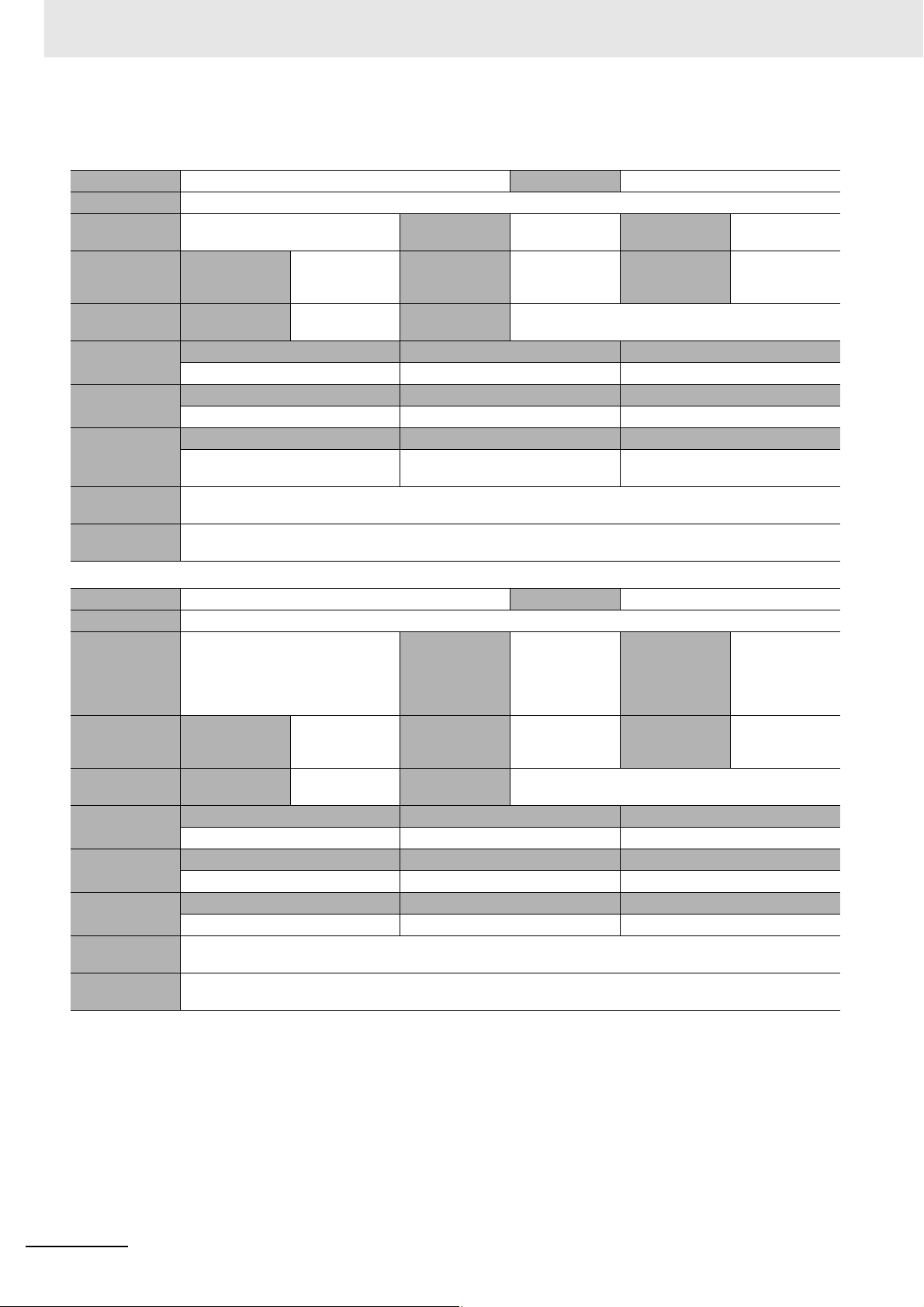
8 Troubleshooting and Maintenance
Error Descriptions
Event name Sensor Communications Error Event code 04C40000 hex
Meaning An error occurred in a Sensor connection.
Source EtherCAT Master Function Module Source details Slave Detection
timing
Error attributes Level Minor fault Recovery Error reset (after
cycling the
power)
Effects User program Continues. Operation Input is not possible from the Sensor. The input data will
Indicators EtherCAT NET RUN EtherCAT NET ERR EtherCAT LINK/ACT
--- --- ---
System-defined
variables
Cause and
correction
Attached
information
Precautions/
Remarks
Variable Data type Name
None --- --Assumed cause Correction Prevention
The Sensor is disconnected. Connect the Sensor again and cycle
the power supply.
None
None
be 0.
Log category System
Connect the Sensor securely.
Continuously
Event name Sensor Communications Has Not Been Established Event code 04C50000 hex
Meaning Communications has not been established with the Sensor.
Source EtherCAT Master Function Module Source details Slave Detection
Error attributes Level Minor fault Recovery Error reset (after
Effects User program Continues. Operation The input data will be 0. Safe-operational state and Oper-
Indicators EtherCAT NET RUN EtherCAT NET ERR EtherCAT LINK/ACT
--- --- ---
System-defined
variables
Cause and
correction
Attached
information
Precautions/
Remarks
Variable Data type Name
None --- --Assumed cause Correction Prevention
A sensor is not connected. Connect at least one Sensor. Connect at least one Sensor.
None
None
automatic slave
recovery)
ational state cannot be entered.
timing
Log category System
When establishing communications after turning
ON power to the
slave.
8 - 10
E3NW-ECT EtherCAT Digital Sensor Communication Unit Operation Manual (E429)
Page 95
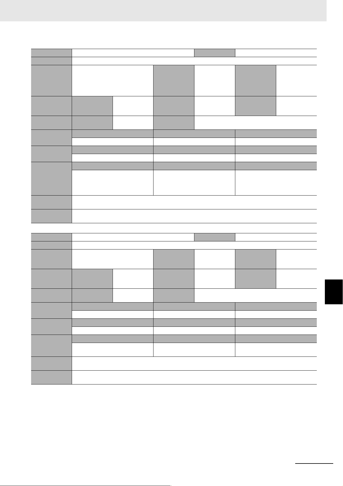
8 Troubleshooting and Maintenance
Event name Non-volatile Memory Checksum Error Event code 14A00000 hex
Meaning An error occurred in the control parameters.
Source EtherCAT Master Function Module Source details Slave Detection
timing
Error attributes Level Minor fault Recovery Error reset (after
cycling slave
power)
Effects User program Continues. Operation The slave's I/O communications stop and the outputs turn
OFF.
Indicators EtherCAT NET RUN EtherCAT NET ERR EtherCAT LINK/ACT
--- Flashes at 1-s intervals. ---
System-defined
variables
Cause and
correction
Attached
information
Precautions/
Remarks
Variable Data type Name
None --- --Assumed cause Correction Prevention
Noise Return the control parameters to their
default settings using restore parameters (1011 hex) of the EtherCAT
Slave.
None
None
Log category System
Implement noise countermeasures.
When establishing communications after turning
ON power to the
slave
Event name Number of Distributed Sensor Unit Verify Error Event code 247A0000 hex
Meaning The number of Distributed Sensor Unit that is checked at power up is decreased.
Source EtherCAT Master Function Module Source details Slave Detection
timing
Error attributes Level Minor fault Recovery Error reset (after
automatic slave
recovery)
Effects User program Continues. Operation Operation continues with the Distributed Sensor Units that
are actually connected.
Indicators EtherCAT NET RUN EtherCAT NET ERR EtherCAT LINK/ACT
--- --- ---
System-defined
variables
Cause and
correction
Attached
information
Precautions/
Remarks
Variable Data type Name
None --- --Assumed cause Correction Prevention
The Distributed Sensor Unit is discon-
nected.
None
The case that the number of Distributed Sensor Unit is increased is not applicable.
Connect the Sensor securely. Connect the Sensor securely.
Log category System
When establishing communications
8-1 Troubleshooting
8
8-1-4 Sysmac Error Status Codes
E3NW-ECT EtherCAT Digital Sensor Communication Unit Operation Manual (E429)
8 - 11
Page 96

8 Troubleshooting and Maintenance
Event name Number of Sensors Over Limit Event code 247B0000 hex
Meaning Too many Sensors are connected.
Source EtherCAT Master Function Module Source details Slave Detection
timing
Error attributes Level Minor fault Recovery Error reset (after
automatic slave
recovery)
Effects User program Continues. Operation The relevant slave will go to the Init state. I/O communica-
tions and message communications are not possible for
the relevant slave.
Indicators EtherCAT NET RUN EtherCAT NET ERR EtherCAT LINK/ACT
--- --- ---
System-defined
variables
Cause and
correction
Attached
information
Precautions/
Remarks
Variable Data type Name
None --- --Assumed cause Correction Prevention
More than the maximum number of
Sensors are connected.
None
None
This event occurs when the cause of
the error is removed and communications for the relevant slave recover.
Simply reset the error in the Controller.
Log category System
Do not connect more than the maximum number of Sensors.
Continuously
Event name Number of Sensors Verify Error Event code 247C0000 hex
Meaning The number of Sensors that is connected does not agree with the settings.
Source EtherCAT Master Function Module Source details Slave Detection
Error attributes Level Minor fault Recovery Error reset (after
Effects User program Continues. Operation Operation continues with the Sensors that are actually
Indicators EtherCAT NET RUN EtherCAT NET ERR EtherCAT LINK/ACT
--- --- ---
System-defined
variables
Cause and
correction
Attached
information
Precautions/
Remarks
Variable Data type Name
None --- --Assumed cause Correction Prevention
The set value does not match the
number of Sensors that are actually
connected.
None
The case that the number of Sensors is decreased in disconnecting Distributed Sensor Unit is applicable. The case
that the number of Sensors is increased in connecting Distributed Sensor Unit is not applicable.
If the setting of the number of connected Sensors is incorrect, correct
the set value. If the number of Sensors that are connected is incorrect,
correct the Sensor connections and
cycle the power supply. If the number
of Sensors are decreased in disconnecting Distributed Sensor Unit,
re-connect the Distributed Sensor
Unit.
cycling the
power)
connected.
timing
Log category System
Make sure that the setting of the number of connected Sensors agrees with
the number of Sensors that are actually connected.
Continuously
8 - 12
E3NW-ECT EtherCAT Digital Sensor Communication Unit Operation Manual (E429)
Page 97

8 Troubleshooting and Maintenance
Event name Number of Sensors Over at Distributed Sensor Unit Event code 247D0000 hex
Meaning Too many Sensors are connected at Distributed Sensor Unit.
Source EtherCAT Master Function Module Source details Slave Detection
timing
Error attributes Level Minor fault Recovery Error reset (after
automatic slave
recovery)
Effects User program Continues. Operation I/O communications and message communications are
not possible for the Sensors with relevant Distributed Sensor Unit.
Indicators EtherCAT NET RUN EtherCAT NET ERR EtherCAT LINK/ACT
--- --- ---
System-defined
variables
Cause and
correction
Attached
information
Precautions/
Remarks
Variable Data type Name
None --- --Assumed cause Correction Prevention
More than the maximum number of
Sensors are connected at Distributed
Sensor Unit.
None
None
Reduce the number of Sensors at relevant Distributed Sensor Unit to less
than the maximum number of Sensors at Distributed Sensor Unit.
Log category System
Do not connect more than the maximum number of Sensors at Distributed Sensor Unit.
Continuously
Event name Dummy Sensors Setting Error Event code 34F80000 hex
Meaning Too many Dummy Units are set.
Source EtherCAT Master Function Module Source details Slave Detection
timing
Error attributes Level Minor fault Recovery Errors reset Log category System
Effects User program Continues. Operation Not affected.
Indicators EtherCAT NET RUN EtherCAT NET ERR EtherCAT LINK/ACT
--- --- ---
System-defined
variables
Cause and
correction
Attached
information
Precautions/
Remarks
Variable Data type Name
None --- --Assumed cause Correction Prevention
There are too many Dummy Units set,
so some Sensors are not assigned
logical unit numbers.
None
None
Reduce the number of Dummy Units
that is set in the dummy function settings so that logical unit numbers can
be assigned to all connected Sensors, and then change the Sensors
from the Init state to Pre-operational
state or restart the Sensors.
Set Dummy Units so that logical unit
numbers can be assigned to all Sensor Amplifiers that are connected.
When establishing communications
8-1 Troubleshooting
8
8-1-4 Sysmac Error Status Codes
E3NW-ECT EtherCAT Digital Sensor Communication Unit Operation Manual (E429)
8 - 13
Page 98

8 Troubleshooting and Maintenance
Event name Non-volatile Memory Hardware Error Event code 04A10000 hex
Meaning An error occurred in non-volatile memory.
Source EtherCAT Master Function Module Source details Slave Detection
timing
Error attributes Level Observation Recovery --- Log category System
Effects User program Continues. Operation Non-volatile memory cannot be written.
Indicators EtherCAT NET RUN EtherCAT NET ERR EtherCAT LINK/ACT
--- --- ---
System-defined
variables
Cause and
correction
Attached
information
Precautions/
Remarks
Variable Data type Name
None --- --Assumed cause Correction Prevention
Non-volatile memory failure Replace the EtherCAT Communica-
tions Unit or the EtherCAT slave.
None
This error is not recorded in the error log of the slave.
None
When establishing communications after turning
ON power to the
slave
8 - 14
E3NW-ECT EtherCAT Digital Sensor Communication Unit Operation Manual (E429)
Page 99

8-1-5 Emergency Error Code
The table below shows types of emergency error codes used in E3NW-ECT EtherCAT Sensor
Communication Units and corresponding error contents.
Error codes common to E3NW-ECT EtherCAT Sensor
Communication Units
8 Troubleshooting and Maintenance
Error
code
5530 hex
6140 hex
6330 hex
7030 hex
Name of error Contents
A timeout was
Non-volatile
Memory
Hardware Error
Slave Unit
Verification
Error
Non-volatile
Memory
Checksum
Error
Slave
Hardware Error
detected when writing
data to non-volatile
memory during
EtherCAT
communications.
At turning ON the
power supply, a
verification error
occurred on the Slave
Unit information stored
in the Slave Unit.
An error occurred in
non-volatile memory
data in the Slave Unit.
A hardware error
occurred in the
EtherCAT
communications area.
Diagnosis
history
Not
saved
Saved
Saved Can be notified
Saved
Notification to
EtherCAT
Master Unit
Can be notified Write the data again.
Cannot be
notified
Cannot be
notified
Measures
If the error occurs
even after restarting
the power supply, the
Slave Unit is
damaged. Replace the
Slave Unit.
A non-volatile memory
data error occurred.
Initialize non-volatile
memory from a
Configuration Tool or
with SDO
communications, and
then restart the Slave
Unit.
(Target indexes: 1011
hex Restore default
parameters
(parameter restore))
If the error occurs
even after restarting
the power supply, the
Slave Units is
damaged. Replace the
Slave Units.
8-1 Troubleshooting
8
8-1-5 Emergency Error Code
E3NW-ECT EtherCAT Digital Sensor Communication Unit Operation Manual (E429)
8 - 15
Page 100

8 Troubleshooting and Maintenance
8-1-6 Application Layer Status Codes
The AL status codes that are used by the E3NW-ECT EtherCAT Sensor Communication Units are
described in the following table.
AL status codes of E3NW-ECT EtherCAT Sensor Communication
Units
AL status
code
0001 hex
0011 hex
0012 hex
0014 hex
0016 hex
001B hex
001D hex
001E hex
001F hex
0024 hex
0025 hex
Name of error Contents
Non-volatile
Memory Control
Data Error
Illegal State
Transition
Request
Received
Error St at e
Transition
Received
Slave Unit
Verification
Error
Mailbox Setting
Error
Process Data
WDT Error
RxPDO Setting
Error
TxPDO Setting
Error
PDO WDT
Setting Error
TxPDO
Assignment
Error
RxPDO
Assignment
Error
An error was detected in
non-volatile memory data
in the Slave Unit.
An illegal state transition
request was received.
A transition request to an
unknown state was
received.
A verification error
occurred in the slave
information stored in the
Slave Units when the
power supply was turned
ON.
An incorrect setting was
detected in the mailbox of
the Sync Manager.
A timeout was detected
for an I/O data
transmission frame.
An error was detected in
the RxPDO settings (e.g.,
a logic setting error in the
Sync Manager).
An error was detected in
the TxPDO settings (e.g.,
a logic setting error in the
Sync Manager).
An incorrect PDO WDT
setting was detected.
An incorr
setting was made (e.g., an
index, subindex, or size
that is
registered).
An incorrect RxPDO
setting was made (e.g., an
index, subindex, or size
that is out of range was
registered).
ect TxPDO
out of range was
Diagnosis
history
Saved
Not
saved
Not
saved
Saved
Not
saved
Not
saved
Not
saved
Not
saved
Not
saved
Not
saved
Not
saved
Notification
to EtherCA T
Master Unit
Can be
notified
Can be
notified
Can be
notified
Can be
notified
Can be
notified
Can be
notified
Can be
notified
Can be
notified
Can be
notified
Can be
notified
Can be
notified
Measures
Initialize non-volatile
memory (execute restore
parameter), and then
restart the Slave Unit.
None
None
If cycling the power
supply does not solve
the problem, the Slave
Unit has failed. Replace
the Slave Unit.
Check the mailbox
settings in the Master
Unit.
Check the WDT settings
in the Master Unit.
Check the Sync
Manager settings in the
Master Unit.
Check the Sync
Manager settings in the
Master Unit.
Check the WDT settings
in the Master Unit.
Check the TxPDO
assignment settings in
the Master Unit.
Check the RxPDO
assignment settings in
the Master Unit.
8 - 16
E3NW-ECT EtherCAT Digital Sensor Communication Unit Operation Manual (E429)
 Loading...