

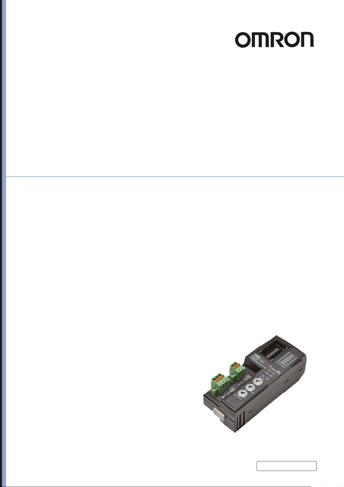
E3NW-CCL
CC-Link Digital Sensor
Communications Unit
User’s Manual
Cat. No. E431-E1-09

NOTICE
(1) No part of this publication may be reproduced, stored in a retrieval system, or transmitted, in any
form, or by any means, mechanical, electronic, photocopying, recording, or otherwise, without the
prior written permission of OMRON.
(2) Because OMRON is constantly striving to improve its high-quality products, the information
contained in this manual is subject to change without notice.
(3) Every precaution has been taken in the preparation of this manual. Nevertheless, OMRON
assumes no responsibility for errors or omissions. Neither is any liability assumed for damages
resulting from the use of the information contained in this publication. If you find any problems in
this manual, please contact your OMRON representative. If you do so, please provide the Cat. No.
that is given at the back of this manual.
Trademarks
“CC-Link” is a registered trademark of Mitsubishi Electric Corporation. It is managed by the
CC-Link Partner Association.
GX-Works2 and GX-Developer are registered trademarks of Mitsubishi Electric Corporation.
Other system names and product names used in this manual are the trademarks or registered
trademarks of the respective companies.

Introduction
Thank you for purchasing the E3NW-CCL CC-Link Digital Sensor Communications Unit.
This manual contains information required to use the E3NW-CCL.
Please read this manual carefully and be sure you
attempting to use the E3NW-CCL.
After reading this manual, keep it in a safe an
Intended Audience
unde
rstand the information provided before
d convenient location
for future reference.
This manual is intended for the following personnel, who must al
systems (an electrical engineer or the equivalent).
• Personnel in charge of installing FA s
• Personnel in charge of designing FA systems.
• Personnel in charge of managing F
ystems.
A facilities.
so have knowledge of electrical
E3NW-CCL CC-Link Digital Sensor Communications Unit User’s Manual (E431)
1
4 - 5
4 Mounting and Wiring
E3NW-CCL CC-Link Digital Sensor Communications Unit User’s Manual (E431)
4-2 Wiring the CC-Link Network
4
4-2-2 Preparing for Wiring
FANC-110SBH CC-Link Cabl e (Kuramo Electric Co.)
Refer to documentation for the CC-Link master unit and the CC-Link Installation Guide for
specifications and processing methods (including stripping methods) for the special CC-Link cable.
35505-6000-BOMGF Power Clamp Connector
1
Strip 4 cm of the insulating sheath from the CC-Link Version 1.10-compliant cable.
2
Separate the braided shield and drain wires, and then twist the drain wire with your
fingers at least 10 times.
Be careful not to sever the drain wire.
3
Cut off the braided shield, ALPET shield tape, and filler.
4
Separate the wires so that they are in the following order: blue, white, yellow, and drain
wire.
Blue wire, pin 1 (cover label: DA B)
White wire, pin 2 (cover label: DB W)
Yellow wire, pin 3 (cover label: DG Y)
Drain wire, pin 5 (cover label: SL D)
5
Insert the cable all the way into the power clamp.
Check to confirm that the wire has been inserted all the way by looking through the top of the
cover.
6
Use pliers to push the cover into the body and crimp the cable.
7
Check to confirm that the cover is level with the body and that there is no space between
the body and the cover.
* We recommend using heat-shrinking tubing to protect the drain wire and other wiring.
Reference
For details, refer to the 3M Power Clamp Connector Wiring Procedures.
4-2-2 Preparing for Wiring
Manufacturer Model number
FGMOB-0006-50553M3 omotimuS
Wiring the Connector
4 Mounting and Wiring
4 - 4
E3NW-CCL CC-Link Digital Sensor Communications Unit User’s Manual (E431)
4-2 Wiring the CC-Link Network
To connect the Communications Unit to the CC-Link network, refer to documentation for the CC-Link
master unit and the CC-Link Installation Guide.
• Always turn OFF the power supply before performing any wiring operations on the Communications
Unit. The external devices that are connected to the E3NW-CCL may operate in an unexpected
manner if the E3NW-CCL is wired while the power supply is ON.
• Be careful not to pinch your fingers when attaching connectors.
• Incorrect wiring will reduce safety functions. Perform all wiring correctly and confirm operation before
using the Communications Unit.
Special Screwdrivers
We recommend using the following Special Screwdrivers to tighten wiring screws when wiring the
power supply or connecting the enclosed DS-bus connector cables.
Contact Information
OMRON FA Store
Telephone: 03-5435-6481
FAX: 0120-024524 (Toll Free)
URL: http://store.fa.omron.jp/
4-2-1 General Wiring Precautions
Special Connector Tools
Model Manufacturer (supplier)
NORMOC00-Z4WX
.erotS AF NORMO eht morf desahcrup eb naC1-FZS
Icons
(See next page.)
Level-2
heading
Gives the current
level-2 heading.
Numbered
step in procedure
These numbers indicate
a procedure.
Level-3
heading
Page tab
Gives the number of the level-1 section.
Level-2 heading
Gives the current level-2 heading.
Level-3 heading
Gives the current level-3 heading.
Level-1
heading
Manual name
Reading This Manual
Page Structure
The following page structure is used in this manual.
2
E3NW-CCL CC-Link Digital Sensor Communications Unit User’s Manual (E431)

Icons
Precautions for Safe Use
Precautions for Correct Use
Additional Information
The following icons are used in this manual.
Precautions on what to do and what not to do to ensure using the product safely.
Precautions on what to do and what not to do to ensure proper operation and performance.
Convenient information or information for reference in product application.
E3NW-CCL CC-Link Digital Sensor Communications Unit User’s Manual (E431)
3

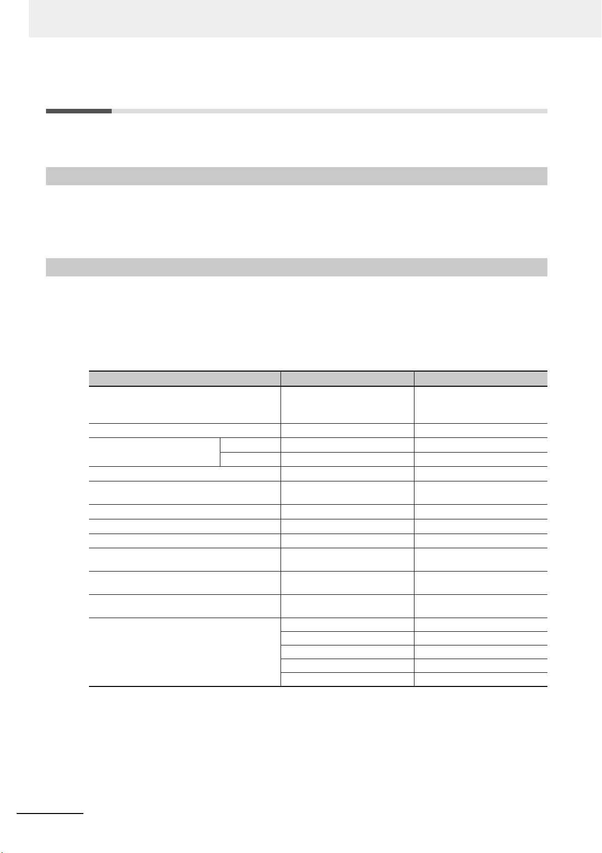
Structure of This Manual
This manual consists of the following sections.
Section Description
Section 1 CC-Link Configuration Elements
Section 2 About the E3NW-CCL Provides an overview of the E3NW-CCL.
Section 3 Basic Application Procedures
Section 4 Mounting and Wiring
Section 5 E3NW-CCL Hardware Specifications Provides the hardware specifica
Section 6 E3NW-CCL Function Specifications Describes the functions of the E3NW-CCL.
Section 7 Troubleshooting and Maintenance
Appendices Appendices
Describes the features of CC-Link and th
elements in a network.
Describes how to set up and use a Communications Unit
based
Describes how to mount the E3NW-CCL and how to
connect the CC-Link n
and wire the E3NW-CCL.
Describes troubleshooting and inspections for the person
that will perform trou
Describes executable commands, program examples,
and the specifications
Unit.
on a simple system
etwork, connect the power supply,
bleshooting and routine inspections.
of the E3NW-DS Distributed Sensor
e configuration
setting example.
tions of
the E3NW-CCL.
4
E3NW-CCL CC-Link Digital Sensor Communications Unit User’s Manual (E431)

Terms and Conditions Agreement
Warranty, Limitations of Liability
Warranties
Exclusive Warranty
Omron’s exclusive warranty is that the Products will be free from defects in materials and
workmanship for a period of twelve months from the date of sale by Omron (or such other period
expressed in writing by Omron). Omron disclaims all other warranties, express or implied.
Limitations
OMRON MAKES NO WARRANTY OR REPRESENTATION, EXPRESS OR IMPLIED, ABOUT
NON-INFRINGEMENT, MERCHANTABILITY OR FITNESS FOR A PARTICULAR PURPOSE OF
THE PRODUCTS. BUYER ACKNOWLEDGES THAT IT ALONE HAS DETERMINED THAT THE
PRODUCTS WILL SUITABLY MEET THE REQUIREMENTS OF THEIR INTENDED USE.
Omron further disclaims all warranties
on infringement by the Products or otherwise of any intellectual property right.
and respons
ibility of any type for claims or expenses based
Buyer Remedy
Omron’s sole obligation hereunder shall be, at Omron’s election, to (i) replace (in the form originally
shipped with Buyer responsible for labor charges for removal or replacement thereof) the
non-complying Product, (ii) repair the non-complying Product, or (iii) repay or credit Buyer an
amount equal to the purchase price of the non-complying Product; provided that in no event shall
Omron be responsible for warranty, repair, indemnity or any other claims or expenses regarding the
Products unless Omron’s analysis confirms that the Products were properly handled, stored,
installed and maintained and not subject to contamination, abuse, misuse or inappropriate
modification. Return of any Products by Buyer must be approved in writing by Omron before
shipment. Omron Companies shall not be liable for the suitability or unsuitability or the results from
the use of Products in combination with any electrical or electronic components, circuits, system
assemblies or any other materials or substances or environments. Any advice, recommendations or
information given orally or in writing, are not to be construed as an amendment or addition to the
above warranty.
See http://www.omron.com/global/ or contact your Omron representative for published information.
Limitation on Liability; Etc
OMRON COMPANIES SHALL NOT BE LIABLE FOR SPE
CONSEQUENTIAL DAMAGES, LOSS OF PROFITS OR PRODUCTION OR COMMERCIAL LOSS IN
ANY WAY CONNECTED WITH THE PRODUCTS, WHETHER SUCH CLAIM IS BASED IN
CONTRACT, WARRANTY, NEGLIGENCE OR STRICT LIABILITY.
Further, in no event shall liability of Omron
which liability is asserted.
Companies exce
CIAL, INDIRECT, INCID
ed the individual price of the Product on
ENTAL, OR
E3NW-CCL CC-Link Digital Sensor Communications Unit User’s Manual (E431)
5

Application Considerations
Suitability of Use
Omron Companies shall not be responsible for conformity with any standards, codes or regulations
which apply to the combination of the Product in the Buyer’s application or use of the Product. At
Buyer’s request, Omron will provide applicable third party certification documents identifying ratings
and limitations of use which apply to the Product. This information by itself is not sufficient for a
complete determination of the suitability of the Product in combination with the end product, machine,
system, or other application or use. Buyer shall be solely responsible for determining appropriateness
of the particular Product with respect to Buyer’s application, product or system. Buyer shall take
application responsibility in all cases.
NEVER USE THE PRODUCT FOR AN APPLICATION INVOL
PROPERTY OR IN LARGE QUANTITIES WITHOUT ENSURING THAT THE SYSTEM AS A WHOLE
HAS BEEN DESIGNED TO ADDRESS THE RISKS, AND THAT THE OMRON PRODUCT(S) IS
PROPERLY RATED AND INSTALLED FOR THE INTENDED USE WITHIN THE OVERALL
EQUIPMENT OR SYSTEM.
VING SERIOUS RISK TO
LIFE OR
Programmable Products
Omron Companies shall not be responsible for the user’s programming of a programmable Product, or
any consequence th
Disclaimers
Performance Data
Data presented in Omron Company websites, catalogs and
the user in determining suitability and does not constitute a warranty. It may represent the result of
Omron’s test conditions, and the user must correlate it to actual application requirements. Actual
performance is subject to the Omron’s Warranty and Limitations of Liability.
Change in Specifications
Product specifications and accessories may be changed
reasons. It is our practice to change part numbers when published ratings or features are changed, or
when significant construction changes are made. However, some specifications of the Product may be
changed without any notice. When in doubt, special part numbers may be assigned to fix or establish
key specifications for your application. Please consult with your Omron’s representative at any time to
confirm actual specifications of purchased Product.
ereof.
other materi
at any time b
als is provided as a guide for
ased on improvements and other
Errors and Omissions
chec
Information presented by Omron Companies has been
however, no responsibility is assumed for clerical, typographical or proofreading errors or omissions.
6
E3NW-CCL CC-Link Digital Sensor Communications Unit User’s Manual (E431)
ked and is believed to be accurate;
Safety Precautions
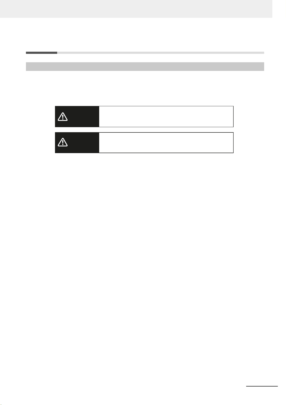
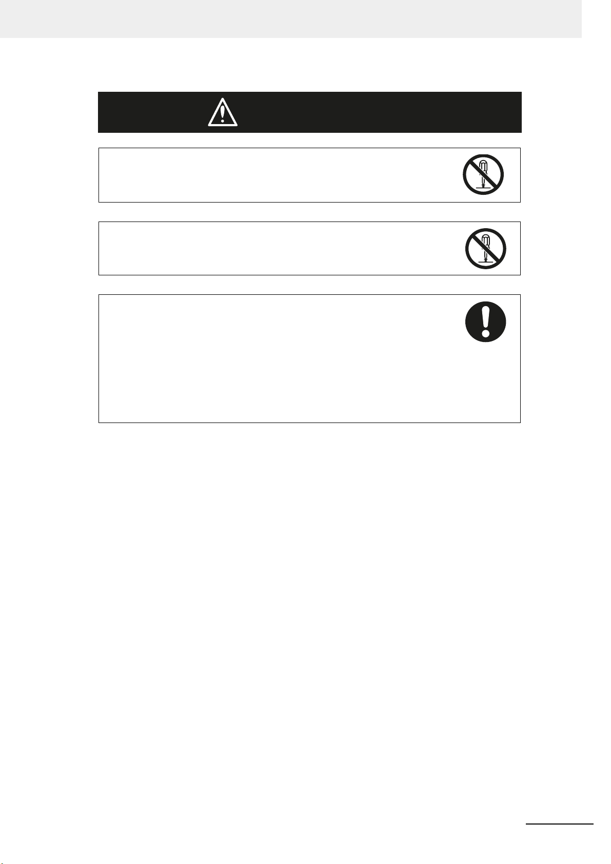
WARNING
Caution
Indicates a potentially hazardous situation which, if not
avoided, could result in death or serious injury. Additionally
there may be severe property damage.
Indicate a potentially hazardous situation which, if not
avoided, may result in minor or moderate injury, or property
damage.
Definition of Precautionary Information
This manual uses the following signs and symbols to ensure safe operation of this product.
These signs and symbols are important for avoiding personal injury or damage to the product. Make
hat they are observed.
sure t
E3NW-CCL CC-Link Digital Sensor Communications Unit User’s Manual (E431)
7
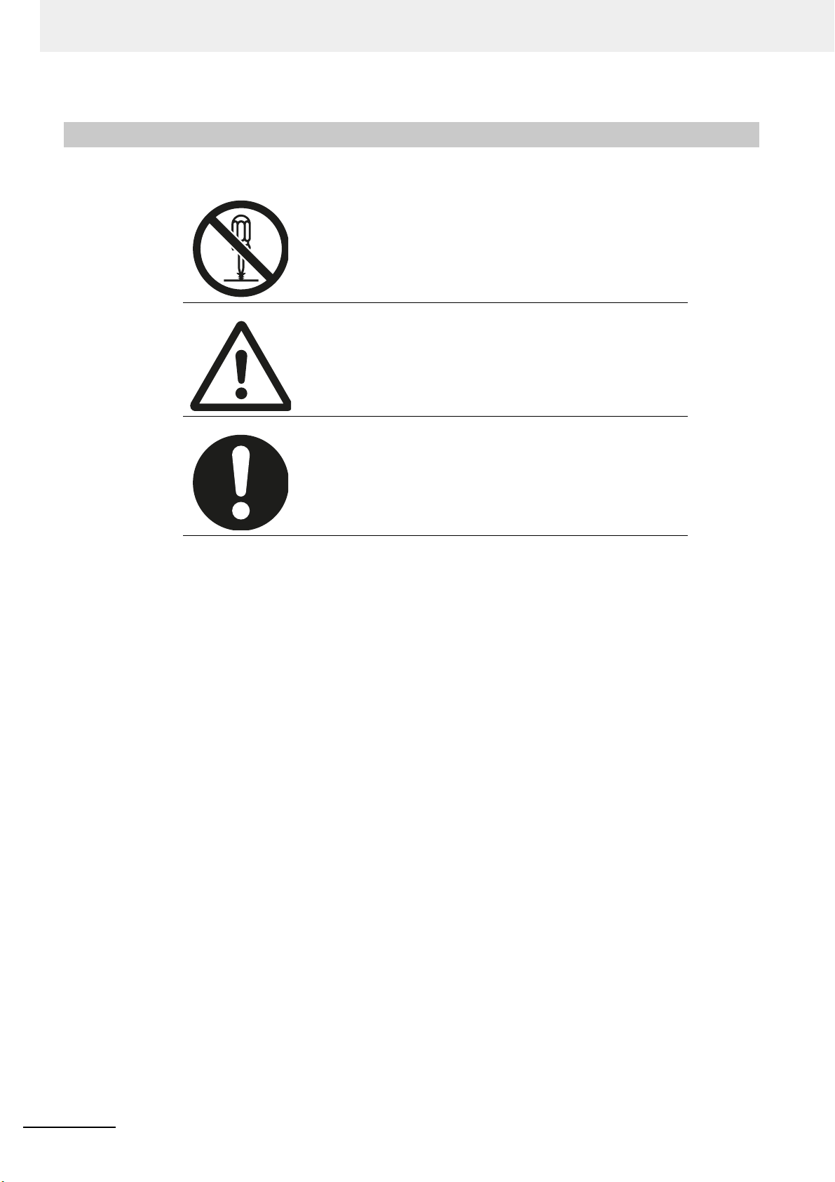
Symbols
The circle and slash symbol indicates operations that you must not
do.
The specific operation is shown in the circle and explained in text.
This example indicates prohibiting disassembly.
The triangle symbol indicates precautions (including warnings).
The specific operation is shown in the
This example indicates a general precaution.
triangle
and explained in text.
The filled circle symbol indicates operations that you must do.
The specific operation is shown in the circle and explained in text.
This example shows a general precaution for something that you
must do.
8
E3NW-CCL CC-Link Digital Sensor Communications Unit User’s Manual (E431)
Do not touch the terminals or disassemble the Unit and touch any internal
WARNING
components while power is being supplied. Do not supply power while the cover is
open.
Doing so may result in electric shock.
Do not attempt to disassemble, repair, or modify any Unit
may res
Provide safety measures in external circuits, i.e., not in the Sensor Communi
Unit, in order to ensure safety in the system if an abnormality occurs due to
malfunction of the PLC or another external factor affecting the PLC operation. Not
doing so may result in serious accidents.
(1) Emergency stop circuits, interlock circuit
(2) The outputs from the Sensor Communications Unit may remain ON or OFF
ult in electric shock.
s, limit circuits, and similar safety
measures
due
transistors. As a countermeasure for such problems, external safety measures
must be provided to ensure safety in the system.
must be provided in external control circuits.
to deposition
or burning of the output relays or destruction of the output
s. Any attempt to do so
cations
E3NW-CCL CC-Link Digital Sensor Communications Unit User’s Manual (E431)
9

Precautions for Safe Use
Observe the following precautions when using the Digital Sensor Communications Unit:
Power Supply
• Take appropriate measures to ensure that the specified power with the rated voltage and
frequency is supplied. Be particularly careful in places where the power supply is unstable.
• Always
of the following.
turn OFF the power supply to the PLC, Slave Units, and other Units before attempting any
embling the Units (Expansion Units)
• Ass
• Mounting or dismounting terminal blocks on Remote I/O Terminals
• Replacing component relays
ches
• Setting DIP swit
• Connecting or wiring the cables
or node address switches
Installation
• Before touching the Unit, be sure to first touch a grounded metallic object in order to discharge
any static buildup.
• Be sur
• Always u
• Be sure that all the terminal screws and cable connector screws of the
• Be sur
• Always u
• Abide by the specifications for the communications
• When using cables in multiple systems, be sure to keep the distance of 5 mm or more between
e that the terminal blocks, communications cables, a
properly locked into place.
se
the enclosed End Plates to securely mount the Units to the DIN Track.
the torque specified in the relevant manuals.
e that the screws of the terminal block are tightene
manuals. Insufficient tightening torque may result in fire, malfunction, or failure.
se
specified communications cables and connectors.
distance and the number of Units to be
connected.
two cables
any
to avoid operational instability due to interference.
nd other items with locking devices are
product are tightened to
d to the torque specified in the relevant
Wiring
• Confirm that the wiring and switch settings are correct before supplying power.
• Use the correct wiring tools to perform wiring.
ty be
• Confirm terminal polari
• Do not let a piece of meta
• Be careful of the following when wiring commu
• Keep communications cables away from power lines and high-voltage lines.
• Do not fold over
• Abide by the specifications for the communications cable distance.
• Do not place objects on top of communications cables.
• Always wire
commu
comm
fore wiring.
l enter the Units when wiring or installing.
nications cables.
nications cables.
unications cables through a duct.
10
E3NW-CCL CC-Link Digital Sensor Communications Unit User’s Manual (E431)

Handling
• Use the special packing box to transport the Unit. Also, protect the Unit from being exposed to
excessive vibration or impact during transportation.
• Do not
• Check the user program for proper execution before actuall
• Confirm that no adverse ef
• Do not use thinner or similar solvent for cleaning. Use commercial alcohol.
forcibly bend or pull the cables.
y running it on the Unit.
fect will occur in the system before attempting any of the following.
• Changing the operating mode of the PLC
g bits
• Force-setting/force-resettin
• Changing the present value or any set value of any word from the user program
in memory
External Circuits
• Install external breakers and take other safety measures against short-circuiting in external wiring.
Applicable standards
• EN61326-1
• Electromagnetic environment : Industrial electromagnetic environment
(EN/IEC 61326-1 Table 2)
E3NW-CCL CC-Link Digital Sensor Communications Unit User’s Manual (E431)
11

Precautions for Correct Use
• Install the Unit properly as shown in this manual. Not doing so may result in a failure of the Unit.
• Do not install the Digital Sensor Communications Unit in locations
• Locations subject to direct sunlight
ts
• Locations subject to temperatures or humidity ou
• Locations subject to condensation as the result of seve
• Locations subject to corrosive or flammable gases
• Locations subject to dust (especially iron dust) or salts
• Locations subject to exposure to water, acid, oil, or chemicals
• Locations subject to shock or vibration
• When you wire the power supply cable, always connect the frame ground (FG).
• Be sure to observe the voltage specifications whe
and power supply, or at I/O crossovers. Wrong wiring may cause a failure of the Unit.
e the Unit properly as indicated in this manual.
• Wir
• Use the correct wiring parts to perform wiring.
• Take appropriate and sufficient countermeasures when using
• Locations subject to static electricity or other forms of noise
el
• Locations subject to strong
• Locations subject to possible exposure to radioactivity
• Locations close to power supplies
• Do not drop the Digital Sensor Communications Unit or e
Doing so may result in damage to the Digital Sensor Communications Unit or malfunction.
e Digital Sensor Communications Unit provides power
• Th
operation of the Sensors may become unstable if there are abnormalities in the power supply, such
as a drop in the power supply voltage at startup. If Sensor operation is unstable, check the voltage
specifications and wiring, and then cycle the power supply.
ectromagnetic fields
ide the range specified in the specifications
re changes in temperature
rforming wiring between communications path
n pe
xp
to the connected Sensors. Therefore, the
subject to the following conditions:
the Un
it in the following locations:
ose it to any excessive vibration or shock.
12
E3NW-CCL CC-Link Digital Sensor Communications Unit User’s Manual (E431)

Conformance to EC Directives
Applicable Directives
• EMC Directive
Concepts
EMC Directive
The Digital Sensor Communications Unit is an electrical device that is built into other machines. To
enable more easily building it into other machines, it has been checked for conformity to EMC
standards.*
EMC-related performance of the Unit w
nditions of the equipment or control panel on which it is installed.
co
The customer must, therefore, perform the final check to confirm
machine conform to EMC standards.
ill vary depending on the configuration, wiring, and other
that devices and the overall
* Note: Applicable EMC (Electromagnetic Compatibility) standards are as follows:
EMS (Electromagnetic Susceptibility): EN 61326-1
EMI (Electromagnetic Interference): EN 61326-1
Conformance to EC Directives
The Digital Sensor Communications Unit complies with EC Directives. To ensure that the machine in
which the Unit is used complies with EC Directives, the Unit must be installed as follows:
• The Unit must be installe
• You must use reinforced insulation or double insulation for the DC power supplies for
communi
when a momentary power interruption of 10 ms occurs in the input.
We recommend using an OMRON S8JX-series Power Supply.*
Products complying with EC Directives also conform to the Emission Standards (EN 61326-1).
•
Radiated emission characteristics (10-m regulations) may vary depending on the configuration of the
control panel used, other devices connected to the control panel, wiring, and other conditions. You must
therefore confirm that the overall machine or equipment complies with EC Directives.
• Compliance was confirmed for I/O wiring of less than 30 m.
* Conformance with the EMC Directive was confirmed when using the recommended power supply.
cations, internal power, and I/O. The DC power supplies must provide stable power even
d within a control panel.
E3NW-CCL CC-Link Digital Sensor Communications Unit User’s Manual (E431)
13
E431-E1-09
Revision code
Cat. No.
Revision History
A manual revision code appears as a suffix to the catalog number at the bottom of the front and back
covers of this manual.
Example
Revision code Date Revised content
01 September 2013 Original production.
02 October 2013
Page 4-6: Changed part of illustration.
Page 7-4: Changed part of illustration.
Page 5: Removed section from top of page.
Pages 6-4 and 6-6: Changed signal name for RX(n+2)2.
Page A-3: Removed row for command type 21.
03 July 2014
04 April 2015
05 July 2015
06 December 2017
07 May 2018
08 February 2019 E3NX-FA and E3NX-MA function added.
09 March 2020 E9NC-TA function added. Corrected mistakes.
Pages 2-2, 2-3, 6-13, A-2 to A-7
information for E9NC-TA0.
Page 4-5: Corrected Power Clamp Connector model number.
Page 6-5: Corrected device numbers in the last
Added accessories.
Deleted connector logo.
Corrected minor errors.
Page 11 : Added applicable standards.
Corrected mistakes.
E3NX-FA function added.
E3NX-MA, FAH/E2NC-EA/E9NC-AA, VA added.
Corrected mistakes.
Added the E9NC-VD.
Corrected mistakes.
, and
A-13: Added/updated
table row.
14
E3NW-CCL CC-Link Digital Sensor Communications Unit User’s Manual (E431)

CC-Link Configuration Elements
This section provides an overview of a CC-Link network.
1-1 CC-Link Connection Example . . . . . . . . . . . . . . . . . . . . . . . . . . . . . . . . . . . . 1-2
1-2 CC-Link Network Configuration Elements . . . . . . . . . . . . . . . . . . . . . . . . . . 1-3
1-2-1 CC-Link Network Configuration Devices . . . . . . . . . . . . . . . . . . . . . . . . . . . . . . 1-3
1-3 Outline of Configuration Devices . . . . . . . . . . . . . . . . . . . . . . . . . . . . . . . . . 1-4
1
E3NW-CCL CC-Link Digital Sensor Communications Unit User’s Manual (E431)
1 - 1
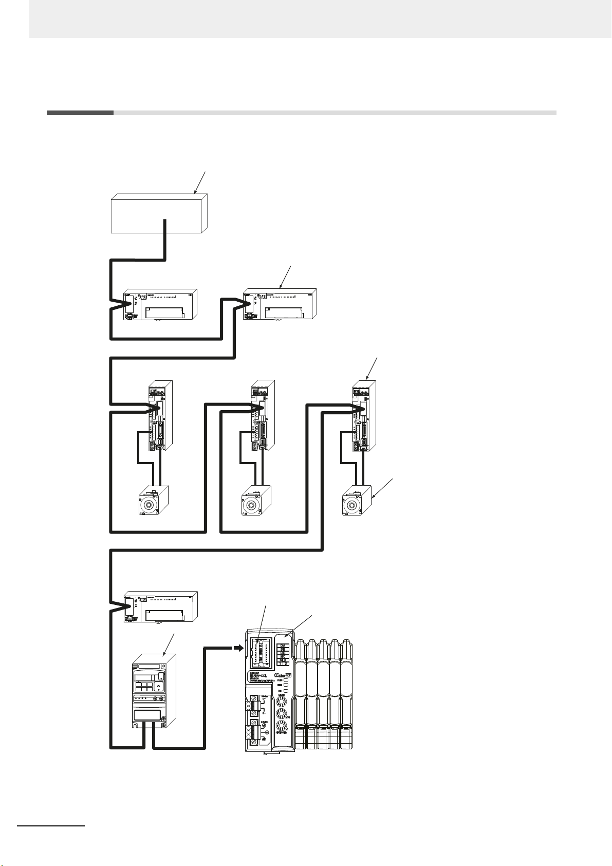
1 CC-Link Configuration Elements
ADR
ADR
ADR
Digital I/O
CC-Link master
Servo drive
Servomotor
Inverter
E3NW-CCL
Sensor Communication Unit
Terminating resistance (110 Ω) must be connected.
Use the Terminating Resistor that is provided with
the master unit.
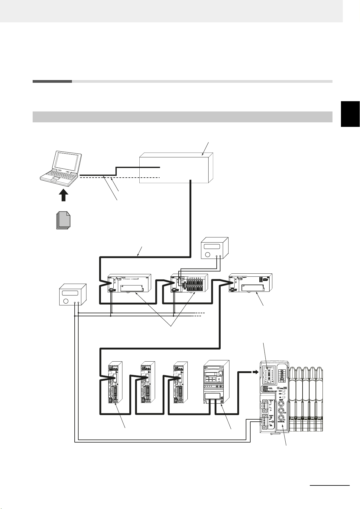
1-1 CC-Link Connection Example
The following figure shows a CC-Link network connection example.
1 - 2
E3NW-CCL CC-Link Digital Sensor Communications Unit User’s Manual (E431)
1 CC-Link Configuration Elements
Terminating resistance (110 Ω) must
be connected. Use the Terminating
Resistor that is provided with the
master unit.
CSP+ file
USB port connection
RS-232C port connection
ADR
ADR
ADR
Communications cable
Unit power supply
I/O power supply
Digital I/O slaves
Analog I/O slave
Servo drive
Inverter
E3NW-CCL
Sensor Communication Unit
CC-Link master
GX-Works2 Engineering Tool
*(or GX-Developer)
Computer
1-2 CC-Link Network Configuration
Elements
This section describes the configuration devices that make up a CC-Link network and their uses.
Configuration Elements
1-2 CC-Link Network
1-2-1 CC-Link Network Configuration Devices
An example of a CC-Link network is shown below.
1
1-2-1 CC-Link Network Configuration Devices
E3NW-CCL CC-Link Digital Sensor Communications Unit User’s Manual (E431)
1 - 3

1 CC-Link Configuration Elements
1-3 Outline of Configuration Devices
This section describes each of the devices in a CC-Link network.
CC-Link Master
The CC-Link master manages the CC-Link network, monitors the
exchanges I/O data with slave units. Refer to CC-Link documentation from Mitsubishi Electric
Corporation or other sources for details on CC-Link.
status of the slave units, and
CC-Link Slaves
ink m
CC-Link slave units output data received from the CC-L
send input data to the CC-Link master unit through the CC-Link network.
There are different types of slaves,
also classified as a CC-Link slave unit.
such a
s digital I/O slaves and analog I/O slaves. The E3NW-CCL is
aster unit over the CC-Link network, and
Communications Cable
Refer to documentation for the CC-Link master unit and the CC-Link Inst
specifications and processing methods (including stripping methods) for CC-Link cable.
allation Guide for the
CSP+ (CC-Link System Profile Plus) File
CSP+ is an abbreviation for CC-Link Family System Profile. A CSP+ file con
information required to start, operate, and maintain a device compatible with CC-Link and CC-Link IE
Field, such as network parameter and memory mapping information.
rameters from the same Engineering Tool.
CC-Link Family users can use CSP+ files to easily se
However, CSP+ can be used only when GX-Works2 is used for the Engineering Tool. The
GX-Devel
oper cannot be used.
t pa
tains a profile of all the
1 - 4
Unit Power Supply
This is the power supply for slave communications and internal operations.
Separate the unit power supply from the I/O power supply.
For details on the E3NW-CCL Unit pow
page 4-8.
er supply,
refer to 4-3 Connecting the Unit Power Supply on
I/O Power Supply
This is the power supply for I/O operations
Separate the I/O power supply from the Unit powe
The E3NW-CCL does not require an I/O power supply.
E3NW-CCL CC-Link Digital Sensor Communications Unit User’s Manual (E431)
with external devices connected to the slave units.
r supply.

About the E3NW-CCL
This section provides an overview of the E3NW-CCL CC-Link Digital Sensor
Communications Unit.
2-1 E3NW-CCL Overview . . . . . . . . . . . . . . . . . . . . . . . . . . . . . . . . . . . . . . . . . . . 2-2
2-1-1 Features of the Sensor Communications Unit . . . . . . . . . . . . . . . . . . . . . . . . . 2-2
2-1-2 E3NW-CCL Operating Modes . . . . . . . . . . . . . . . . . . . . . . . . . . . . . . . . . . . . . . 2-2
2-2 Connectable Sensor Amplifier Units . . . . . . . . . . . . . . . . . . . . . . . . . . . . . . 2-3
2-2-1 List of Sensor Amplifier Units . . . . . . . . . . . . . . . . . . . . . . . . . . . . . . . . . . . . . . 2-3
2-2-2 Number of Connected Sensor Amplifiers . . . . . . . . . . . . . . . . . . . . . . . . . . . . . 2-3
2
E3NW-CCL CC-Link Digital Sensor Communications Unit User’s Manual (E431)
2 - 1
2 About the E3NW-CCL
2-1 E3NW-CCL Overview
This section provides an overview of the E3NW-CCL Sensor Communications Unit.
2-1-1 Features of the Sensor Communications Unit
The Sensor Communications Unit is used to monitor Sens
detection levels, write parameters, and perform operations between Digital Sensors and a PLC with a
CC-Link communications interface.
2-1-2 E3NW-CCL Operating Modes
The E3NW-CCL has two operating modes. The operating
mode setting switch.
Reduced I/O Mode: This mode allows for many devices to
allocated stations and allocated points.
Monitor Mode: This mode allows for realtime monitoring and cont
settings and the monitoring.
Operating mode Reduced I/O Mode Monitor Mode
Remote Network Version 1 Mode
CC-Link mode
Allocated station numbers
Number of allocated nodes
Expanded cyclic setting
Maximum connectable Communications Units in
CC-Link syst
one
Number of connectable Sensors
Maximum connectable Distributed Sensor Units
Sensor ON/OFF status transfer
Simultaneous writing of the same threshold
value to mo
Batch transfer of Sensor Amplifier Unit detection
levels
Se
nsor Amplifier Unit detection level peak value
and bott
Baud rate/operating mode setting switch
*1 This is the total number of Sensor Amplifier Units that can be connected to the Communications Unit and
om value switching
Distributed Sensor Units.
em
re than one Sensor Amplifier Unit
RX/RY
RWr/RWw
*1
Symbols: OK: Supported, NA: Not supported.
Remote Network V
Remote Network Addition Mode
or Amplifier Unit ON/OFF outputs and
mode is selected
be connected by limiting
via the baud rate/operating
the number of
rol to utilize Amplifier Unit
Remote Network Version 2 Mode
ersion 2 Mode
23
64 320
848
--- Quadruple setting
32 21
16 16
88
OK OK
OK OK
NA OK
NA OK
0: 156 kbps 5: 156 kbps
625 kbp
1:
2: 2.5 Mbps 7: 2.5 Mbps
3: 5 Mbps 8: 5 Mbps
4: 10 Mbps 9: 10 Mbps
s 6: 625 kbps
Remote Network Addition Mode
2 - 2
E3NW-CCL CC-Link Digital Sensor Communications Unit User’s Manual (E431)
2 About the E3NW-CCL
Amplifier Units
Sensor Heads
Connectors
Unit 1
Unit 2
Unit 3
Unit 4
Unit 5
Unit 6
Unit 7
Unit 8
Unit 9
Unit 10
Unit 11
Unit 12
Unit 13
Unit 14
Unit 15
Unit 16
Sensor
Communications Unit
2-2 Connectable Sensor Amplifier Units
This section describes the models and features of the Sensor Amplifier Units that can be connected to
the E3NW-CCL.
2-2-1 List of Sensor Amplifier Units
Type Model number Features
Smart Fiber Amplifier Unit E3NX-FA□0
Smart Laser Amplifier Unit E3NC-LA0
Smart Laser Amplifier Unit (CMOS) E3NC-SA0
Contact-typ
Smart Fiber Amplifier Unit E3NX-MA0 Fiber Amplifier with Light Emission/Reception
Smart Fiber Amplifier Unit E3NX-FAH0
Smart Amplifier Separation
Proximity Unit
Smart Analog Input Unit E9NC-AA□0 Current (4 to 20 mA) Inpu
Sma
Smart Analog Input Unit E9NC-VD□0 Voltage Differential (−2 to
* Commands to the E9NC-TA0 are supported from E3NW-CCL Ver. 1100, and the E3NX-MA0, E2NC-EA0, and
E9NC-AA0 / VA0/ VD□0 are supported from E3NW-CCL Ver. 1160.
You can check the version with read command
e Smart Sensor E9NC-TA0 A durable contact-type sensor.
E2NC-EA□0 Proxim
rt Analog Input Unit E9NC-VA□0 Voltage (1 to 5 V) Input Amplifier
"B". (Refer to p
A standard, easy to operate and easy to configure
Fiber Amp
A Laser Sensor that can reliably detect workpieces
e
ven
A CMOS-type Laser Sensor that can reliably detect
step
Fiber Amplifier with Near Infrared Light
Emissio
lifier Unit.
with a small spot diameter
s.
n/Receptio
ity Sensor Amplifier
age A-2)
n
t Amplifier
2 V) Input Amplifier
2-2 Connectable Sensor Amplifier Units
2
2-2-1 List of Sensor Amplifier Units
2-2-2 Number of Connected Sensor Amplifiers
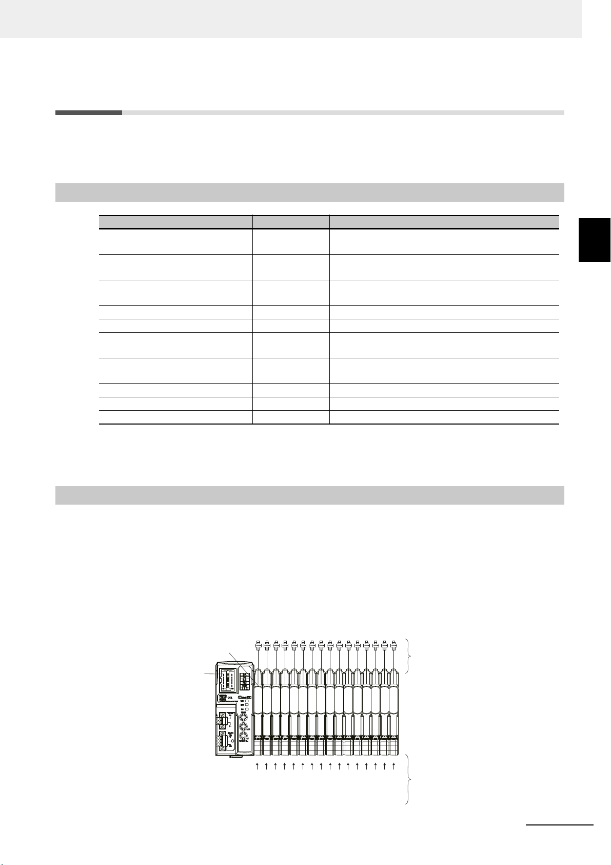
You can connect the Sensor Communications Unit to up to 16 Sensor Amplifier Units, including any
Sensor Amplifier Units connected to Distributed Sensor Units.
Up to 10 Sensor Amplifier Units can be conn
* Also refer to the Sensor Amplifier specifications, as the number of connected units varies depending on the
Sensor Amplifier specifications.
The following are some connection examples.
Example 1: Communications Unit Only
ected to a Distributed
Sensor Unit.
E3NW-CCL CC-Link Digital Sensor Communications Unit User’s Manual (E431)
2 - 3
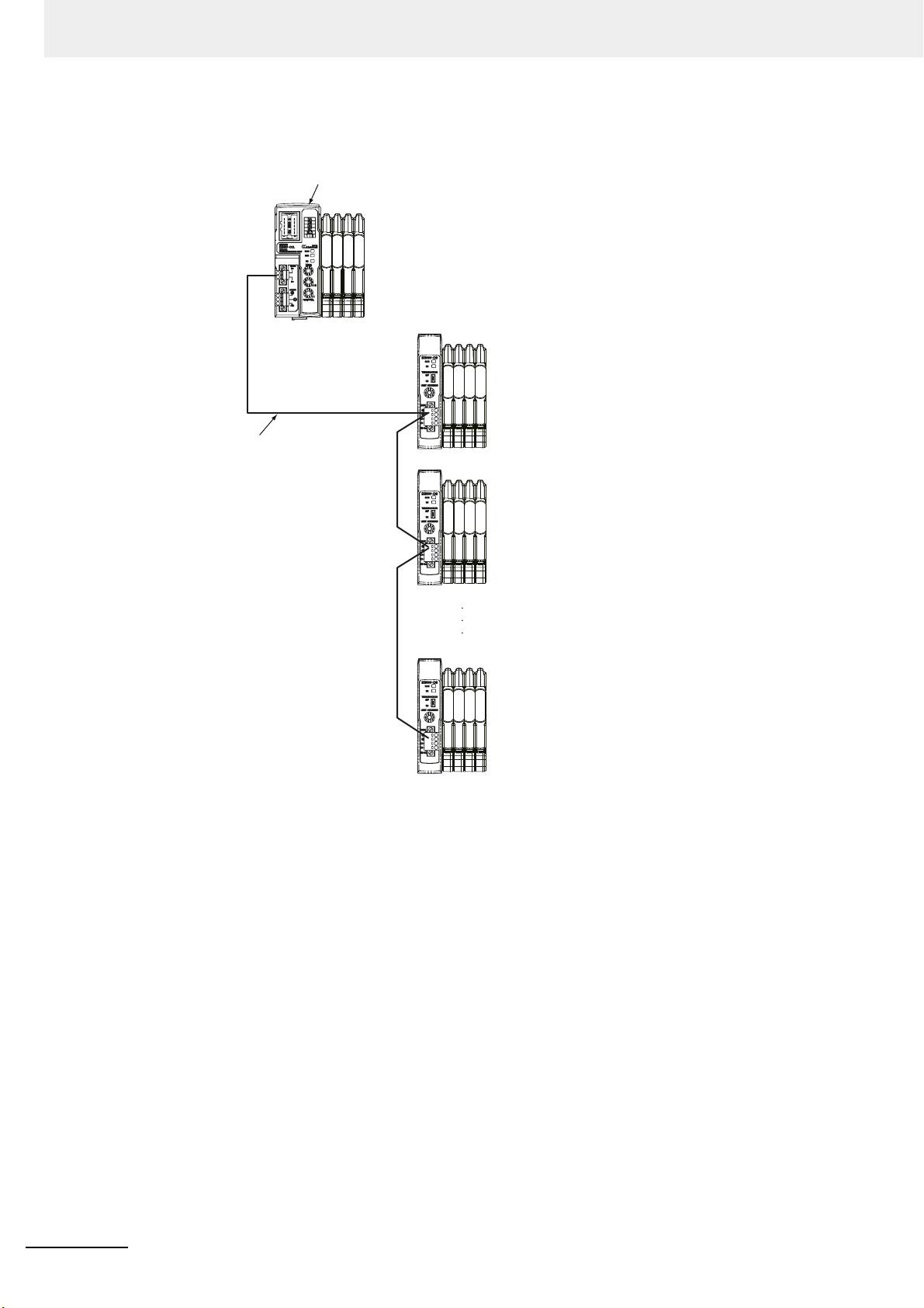
2 About the E3NW-CCL
Sensor Communications Unit
DS-Bus
communications cable
First Sensor Distribution Unit
• Termination setting switch: OFF
Second Sensor Distribution Unit
• Termination setting switch: OFF
nth Sensor Distribution Unit
• “n” is a maximum of 8.
• Termination setting switch: ON
L2
L1
Ln
Example 2: Connecting a Communications Unit and Distributed Sensor Units
2 - 4
E3NW-CCL CC-Link Digital Sensor Communications Unit User’s Manual (E431)

Basic Application Procedures
This section explains how to use E3NW-CCL CC-Link Digital Sensor Communications
Units based on basic setting examples.
3-1 Setting Examples and Basic Procedures . . . . . . . . . . . . . . . . . . . . . . . . . . 3-2
3-1-1 System Setting Example . . . . . . . . . . . . . . . . . . . . . . . . . . . . . . . . . . . . . . . . . . 3-2
3-1-2 Basic Procedures . . . . . . . . . . . . . . . . . . . . . . . . . . . . . . . . . . . . . . . . . . . . . . . 3-3
3-2 Setting and Wiring Hardware . . . . . . . . . . . . . . . . . . . . . . . . . . . . . . . . . . . . 3-4
3-2-1 Mounting and Setting Up the CC-Link Master . . . . . . . . . . . . . . . . . . . . . . . . . 3-4
3-2-2 Mounting and Setting Communications Units . . . . . . . . . . . . . . . . . . . . . . . . . . 3-4
3-2-3 Wiring the Communications Cables . . . . . . . . . . . . . . . . . . . . . . . . . . . . . . . . . 3-4
3-2-4 Connecting the Power Supplies . . . . . . . . . . . . . . . . . . . . . . . . . . . . . . . . . . . . 3-4
3-2-5 Connecting the Sensors . . . . . . . . . . . . . . . . . . . . . . . . . . . . . . . . . . . . . . . . . . 3-4
3-3 Starting Communications . . . . . . . . . . . . . . . . . . . . . . . . . . . . . . . . . . . . . . . 3-5
3-3-1 Starting the System . . . . . . . . . . . . . . . . . . . . . . . . . . . . . . . . . . . . . . . . . . . . . . 3-5
3-3-2 CC-Link Communications Settings . . . . . . . . . . . . . . . . . . . . . . . . . . . . . . . . . . 3-5
3-3-3 Starting CC-Link Communications . . . . . . . . . . . . . . . . . . . . . . . . . . . . . . . . . .3-11
3-4 Confirming Operation . . . . . . . . . . . . . . . . . . . . . . . . . . . . . . . . . . . . . . . . . 3-12
3-4-1 Checking the Unit Displays . . . . . . . . . . . . . . . . . . . . . . . . . . . . . . . . . . . . . . . 3-12
3-4-2 Checking Reading and Writing of Data . . . . . . . . . . . . . . . . . . . . . . . . . . . . . . 3-12
3
E3NW-CCL CC-Link Digital Sensor Communications Unit User’s Manual (E431)
3 - 1
3 Basic Application Procedures
Reference
CC-Link master
Digital I/O slave (16 inputs)
Set the station number to 1. (One station is allocated.)
Digital I/O slave (16 outputs)
Set the station number to 2. (One station is allocated.)
Analog Input Slave (4 inputs)
Set the station number to 3. (Three stations are allocated.)
E3NW-CCL Sensor Communications Unit
Set the station number to 6
(Reduced I/O Mode: Two stations are allocated,
Monitor Mode: Three stations are allocated.)
Up to eight E3NW-DS Units can be connected to one
E3NW-CCL Unit. A maximum of 16 Sensor Amplifier
Units can be connected to the E3NW-CCL, and a
maximum of 10 Sensor Amplifier Units can be
connected to each E3NW-DS. However, a total
maximum of 16 Sensor Amplifier Units can be
connected in one E3NW-CCL system.
3-1 Setting Examples and Basic
Procedures
This section describes how to set up a Sensor Communications Unit based on a simple system setting
example.
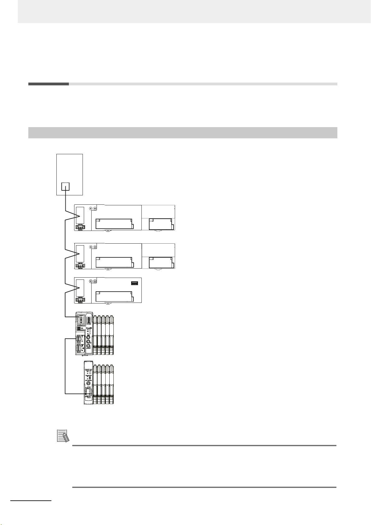
3-1-1 System Setting Example
Connect each of the following slaves to the CC-
Link master
and configure the settings.
3 - 2
The Unit power supply and I/O power supply are not shown in the above figure. They must be
provided
separately.
The setting example provided here demonstrates the basic settings for the E3NW-CCL Sensor
Communications Unit. If more detailed settings are required for actual operations, refer to the
manual for your CC-Link master.
Or, if you are using any slaves other than the E3NW-CCL in your system configuration, refer to
the manuals for those slaves before setting up the system.
E3NW-CCL CC-Link Digital Sensor Communications Unit User’s Manual (E431)
3-1-2 Basic Procedures
Mount and set up the slaves.
Wire the communications cables.
Connect the Sensors.
Start the system.
Start CC-Link communications.
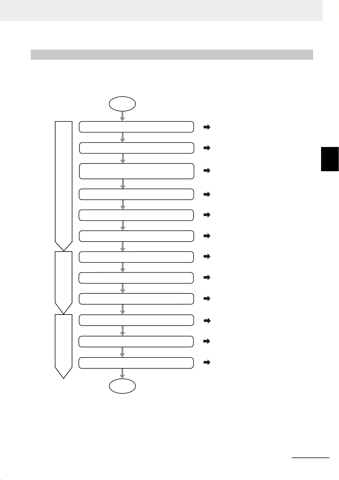
START
Setting and Wiring Hardware
Confirming Operation
3.2.2
3.2.3
3.2.4
3.2.5
3.3.1
3.3.3
3.3.2
Mount and set up Distributed Sensor Units
(if the DS-Bus network is used between Units).
3.2.2
Starting Communications
Mount and set up the CC-Link master.
Check the Unit displays.
Connect the power supplies.
Set up CC-Link communications.
3.2.1
3.4.1
Check reading and writing of data.
3.4.2
END
Set slave parameters.
3.4.3
The following figure shows the flow of procedures for this section.
3 Basic Application Procedures
3-1 Setting Examples and Basic Procedures
3
3-1-2 Basic Procedures
E3NW-CCL CC-Link Digital Sensor Communications Unit User’s Manual (E431)
3 - 3

3 Basic Application Procedures
Reference
3-2 Setting and Wiring Hardware
This section describes how to set up and wire the CC-Link master, Communications Units, and power
supplies.
3-2-1 Mounting and Setting Up the CC-Link Master
Mount the CC-Link master at the specified location and set the unit nu
details, refer to the manual for your CC-Link master.
3-2-2 Mounting and Setting Communications Units
Mount each Communications Unit and Distributed Sensor Unit in th
station numbers and other settings. For details, refer to the following items.
Installation
4-1 Mounting and Removal.
Hardware Settings
5-3-2 Setting Switches on page 5-6
Set the baud rate, operating mode, and station number.
e designated locations, then set the
3-2-3 Wiring the Communications Cables
Connect communications cables to the CC-Link master, Communication
Units. Refer to 4-2 Wiring the CC-Link Network for wiring procedures.
mber and other settings. For
s Units, and Distributed Sensor
3-2-4 Connecting the Power Supplies
Connect the Unit power supply to the CC-Link master, slave
Connect the I/O power supply unit to each slave as required.
For connection method det
diagrams for each slave.
ails, refer to 4-3
Connecting the Unit Power Supply or refer to the wiring
3-2-5 Connecting the Sensors
Connect the Sensor Amplifiers to the Sensors. For connection methods, refer to your Sensor Amplifier
manual.
When using the Distributed Sensor Unit, refer to A-4 Using the Distributed Sensor Unit on page
A-23 as well.
s, and the Distributed Sensor Units.
3 - 4
E3NW-CCL CC-Link Digital Sensor Communications Unit User’s Manual (E431)
3 Basic Application Procedures
3-3 Starting Communications
Start the system, assign the E3NW-CCL I/O data, and then start CC-Link communications.
3-3-1 Starting the System
Turn ON the power supply to the Units in the
1. E3NW-CCL Unit Power Supply
• If you are using Distributed Sensor Units, turn
as well.
2. CC-Link Master Unit Power Supply
following order.
ON the power supply to the Distributed Sensor Units
3-3-2 CC-Link Communications Settings
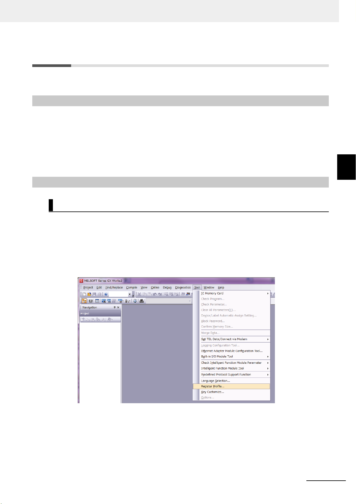
Using CSP+ to Configure Settings in GX-Works2
You can easily set up CC-Link communications for
GX-Works2. This section describes how to configure settings in GX-Works2 with CSP+.
1
Start GX-Works2 on your computer.
the Communications Un
3-3 Starting Communications
3
3-3-1 Starting the System
it by using CSP+ in
2
Register the CSP+ profile in GX-Works2.
−
2-1. Select Tool
Register Profile.
E3NW-CCL CC-Link Digital Sensor Communications Unit User’s Manual (E431)
3 - 5
3 Basic Application Procedures
Reference
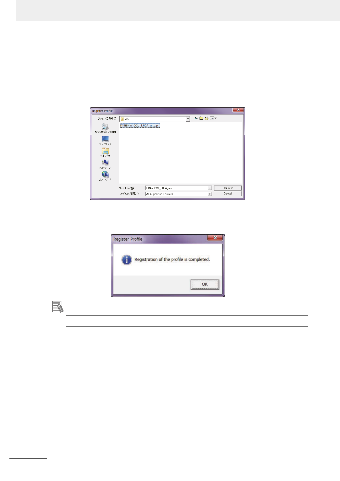
2-2. Register the CSP+ file that you have saved on your computer.
CSP+ can be downloaded from the CC-Link Partner Association website or an OMRON
website,
CC-Link association website: http://www
OMRON website: http://www.fa.omron.co.jp/pr
both listed below.
.cc-link.o
Download and extract "CSP+ File No. 5 Sensor
Encoder", a
nd save CSP+ for the E3NW-CCL.
oducts
rg/jp/csp_plus/index.html
/family/3177/download/software.html
2-3. The registration process is finished when “Registration of th
displayed.
You need to register the CSP+ profile only once.
e profile is completed.” is
3 - 6
E3NW-CCL CC-Link Digital Sensor Communications Unit User’s Manual (E431)

3
Create a new project.
3-1. Select Project − New.
3-2. Set the computer series and type settings for your computer.
3 Basic Application Procedures
3-3 Starting Communications
3
3-3-2 CC-Link Communications Settings
4
Set the CC-Link network parameters.
4-1. Select Parameter − Network Parameter − CC
parameters.
-Link under Project to display the
E3NW-CCL CC-Link Digital Sensor Communications Unit User’s Manual (E431)
3 - 7

3 Basic Application Procedures
4-2. Set the parameters.
(1) Set the Number of Modules to 1.
(2) Set the Start I/O No. .
(3) Set
4-3. Select the Set station information in the CC-
5
Set the CC-Link configuration.
5-1. Select the settings based on your CC-Link system configuration.
You can select and drag Units from the Unit List to make the settings.
5-2. Set the following settings based on the baud rate and operating mode settings for the
5-2-1
the mode for the operating mode you want to use.
To use Reduced I/O Mode, set the mode to Remote Network Version 1 Mode.
To use Monitor Mode, set the mode to Remote Network Version 2 Mode.
Link Configuration Window Check Box, and
then select CC-Link Configuration Settings.
-CCL.
E3NW
. Match the conditions shown in the foll
E3NW-CCL setting switches).
owing locations (i
n GX-Works2 and the
3 - 8
E3NW-CCL CC-Link Digital Sensor Communications Unit User’s Manual (E431)

3 Basic Application Procedures
5-2-2. Set the GX-Works2 settings ((1) to (5)) based on the mode you want to use.
3-3 Starting Communications
Using Reduced I/O Mode
(1) S
elect the same mode that you selected for (3) in 4-2 Wiring the CC-Link Network.
(2) Set the baud rate based on the baud rate set with the baud rate/operating mode
switch on the E3NW-CCL.
(3) Set the station type to Remote device station.
(4) Set to Ver. 1.
(5) Set the exclusive station count to 2 Stations Occupied.
Using Monitor Mode
) Se
(1
(2) Set the baud rate based on the baud rate set with the baud rate/operating mode
(3) Set the station type to Remote device station.
(4) Set to Ver. 2.
(5) Set the exclusive station count to 3 Stations Occupied.
5-2-3. Click the Apply Settings and Close Button.
5-2-4. Click End at
t to Ver. 2 Mode.
switch on the E3NW-CCL.
the bottom of the Netw
ork Parameters screen.
3
3-3-2 CC-Link Communications Settings
E3NW-CCL CC-Link Digital Sensor Communications Unit User’s Manual (E431)
3 - 9

3 Basic Application Procedures
Reference
5-2-5. Write the settings to the master. Select Online - Write to PLC.
Click the Parameter + Program Button, and then click the Execute Button.
Settings are applied when the power supply to the master unit is cycled or when the
master unit is reset.
3 - 10
The setting method described here using CSP+ and GX-Works2 demonstrates the basic
settings for the E3NW-CCL Sensor Communications Unit.
If more detailed settings are required for actual operation, refer to the manual for your CC-Link
master and the manual for GX-Works2.
E3NW-CCL CC-Link Digital Sensor Communications Unit User’s Manual (E431)

3 Basic Application Procedures
Troubleshooting Communications Problems
If the following message is displayed on the computer, the selected Mode Setting does not match
the version of the E3NW-CCL.
Correct the setting.
3-3 Starting Communications
3
3-3-3 Starting CC-Link Communications
If the above error message is not displayed but communications are still not working (i.e., the RUN
indicator on the E3NW-CCL does not light up), check to confirm that the switches for the baud rate,
operating mode, and station number are all set correctly based on the parameters set for the master
station.
Make sure that the station number is unique.
If you changed the baud rate / operating mode and
E3NW-CCL power, restart the E3NW-CCL.
Refer to 7-1 Troubleshooting on page 7-2.
If communications still do not work after checking all of the above s
bleshooting section in the manual for your CC-Link master to determine the cause of the
trou
problem.
3-3-3 Starting CC-Link Communications
Enable CC-Link communications to start CC-Link communications.
Section 6 contains det
ails on the data that can be obtained through communications.
station n
umber switches after turning on the
ettings, refer to the
E3NW-CCL CC-Link Digital Sensor Communications Unit User’s Manual (E431)
3 - 11

3 Basic Application Procedures
3-4 Confirming Operation
If the CC-Link master and E3NW-CCL indicators are all normal, I/O data can be read and written
normally.
L pa
If required, set the E3NW-CC
3-4-1 Checking the Unit Displays
CC-Link Master
Refer to the manual for your CC-Link master.
Communications Unit
Make sure the status indicators on each Communications Unit are as described in the following
table.
rameter settings.
Indicator State
RUN Lit.
ERR Not lit.
Lit green. (The number of actual connections agrees with the number of connections that
SS
were detected when the Unit was started.)
Lit red. (The number of actual connections does not agree with the number of connections
that were detected when the Unit was started.)
Distributed Sensor Unit
Make sure the status indicators on each Distributed Sensor Unit are as described in the following
table.
Indicator State
RUN Lit.
Lit green. (The number of actual connections agrees with the number of connections that
SS
were detected when the Unit was started.)
Lit red. (The number of actual connections does not agree with the number of connections
that were detected when the Unit was started.)
3-4-2 Checking Reading and Writing of Data
Read the input and output data of the CC-Link master to make sure the I/O data is being read and
written correctly.
3 - 12
E3NW-CCL CC-Link Digital Sensor Communications Unit User’s Manual (E431)

Mounting and Wiring
This section describes how to mount and wire the E3NW-CCL.
4-1 Mounting and Removal . . . . . . . . . . . . . . . . . . . . . . . . . . . . . . . . . . . . . . . . . 4-2
4-1-1 Mounting Procedure . . . . . . . . . . . . . . . . . . . . . . . . . . . . . . . . . . . . . . . . . . . . . 4-2
4-1-2 Removal Procedure . . . . . . . . . . . . . . . . . . . . . . . . . . . . . . . . . . . . . . . . . . . . . 4-3
4-2 Wiring the CC-Link Network . . . . . . . . . . . . . . . . . . . . . . . . . . . . . . . . . . . . . 4-4
4-2-1 General Wiring Precautions . . . . . . . . . . . . . . . . . . . . . . . . . . . . . . . . . . . . . . . 4-4
4-2-2 Preparing for Wiring . . . . . . . . . . . . . . . . . . . . . . . . . . . . . . . . . . . . . . . . . . . . . 4-5
4-2-3 Connecting the Communications Cables . . . . . . . . . . . . . . . . . . . . . . . . . . . . . 4-6
4-2-4 Connecting the Distributed Sensor Unit . . . . . . . . . . . . . . . . . . . . . . . . . . . . . . 4-7
4-3 Connecting the Unit Power Supply . . . . . . . . . . . . . . . . . . . . . . . . . . . . . . . 4-8
4-3-1 Precautions on Supplying Unit Power . . . . . . . . . . . . . . . . . . . . . . . . . . . . . . . 4-8
4-3-2 Unit Power Supply Specifications . . . . . . . . . . . . . . . . . . . . . . . . . . . . . . . . . . . 4-8
4-3-3 Connecting the Unit Power Supply . . . . . . . . . . . . . . . . . . . . . . . . . . . . . . . . . . 4-9
4
E3NW-CCL CC-Link Digital Sensor Communications Unit User’s Manual (E431)
4 - 1

4 Mounting and Wiring
4-1 Mounting and Removal
This section describes how to mount the E3NW-CCL and Sensor Amplifier Units to a DIN Track and
how to remove them.
4-1-1 Mounting Procedure
Use the following procedure to mount the Units.
1
Place the top part of the Unit onto the DIN Track.
Sensor Communications Unit
DIN Track
2
Press the bottom part of the Unit onto the DIN Track.
Press
3
Remove the protective cap from the right side of the Sensor Communications Unit. Then,
slide the Sensor Amplifier Unit, align the connector with the Sensor Communications
Unit, and press the Units together until you hear them lock into place.
Sensor Amplifier Units
4 - 2
E3NW-CCL CC-Link Digital Sensor Communications Unit User’s Manual (E431)

4 Mounting and Wiring
2
1
1
2
Do in order: step 1
and then step 2.
Do not perform
step 2 first.
4
Secure the enclosed DIN Track End Plates (PFP-M) onto the ends so that there is no
space between them and the Units. Finally, attach the protective cap you removed in step
3 to the Sensor Amplifier Unit on the far right end.
4-1 Mounting and Removal
Protective cap
Do not reverse the order of steps 1 and 2, above. Doing
so may reduce the mounting strength on the DIN Track.
After you have completed the above procedure, check to make sure that the E3NW-CCL is
mounted securely into place.
4-1-2 Removal Procedure
Use the following procedure to remove the Unit.
DIN Track End Plate
1
2
4
4-1-2 Removal Procedure
1
Slide the Sensor Amplifier Units to separate them from the Sensor Communications Unit.
2
Press in on the Sensor Communications Unit toward the DIN Track and lift up to remove
it.
E3NW-CCL CC-Link Digital Sensor Communications Unit User’s Manual (E431)
4 - 3

4 Mounting and Wiring
4-2 Wiring the CC-Link Network
To connect the Communications Unit to the CC-Link network, refer to documentation for the CC-Link
master unit and the CC-Link Installation Guide.
4-2-1 General Wiring Precautions
• Always
Unit. The e
manner if the E3NW-CCL is wired while the power supply is ON.
• Be
• Incorrect wiring will
using the Communications Unit.
turn OFF the power supply before performing any wiring operations on the Communications
xternal devices that are connected to the E3NW-CCL may operate in an unexpected
careful not to pinch your fingers when attaching connectors.
reduce s
afety functions. Perform all wiring correctly and confirm operation before
Special Connector Tools
Special Screwdrivers
We recommend using the following Special Screwdrivers to tighten wiring screws when wiring the
power supply or connecting the enclosed DS-bus connector cables.
Model Manufacturer (supplier)
XW4Z-00C OMRON
SZF1-0.6X3.5 Screwdriver Can be purchased from the OMRON FA Store.
Contact Information
OMRON FA Store
Telephone: 03-6718-3565
FAX: 0120-024524 (Toll Free)
URL: http://store.fa.omron.co.jp/
4 - 4
E3NW-CCL CC-Link Digital Sensor Communications Unit User’s Manual (E431)

Reference
4-2-2 Preparing for Wiring
FANC-110SBH CC-Link Cable (Kuramo Electric Co.)
Refer to documentation for the CC-Link master unit and the CC-Link Installation Guide for
specifications and processing methods (including stripping methods) for the special CC-Link cable.
Network connector 35505-6000-B0MGF (Sumitomo 3M)
Two are provided as accessories.
Wiring the Connector
1
Strip 4 cm of the insulating sheath from the CC-Link Version 1.10-compliant cable.
2
Separate the braided shield and drain wires, and then twist the drain wire with your
fingers at least 10 times.
Be careful not to sever the drain wire.
4 Mounting and Wiring
4-2 Wiring the CC-Link Network
3
Cut off the braided shield, ALPET shield tape, and filler.
4
Separate the wires so that they are in the following order: blue, white, yellow, and drain
wire.
Blue wire, pin 1 (cover label: DA B)
White wire, pin 2 (cover label: DB W)
Yellow wire, pin 3 (cover label: DG Y)
Drain wire, pin 5 (cover label: SL D)
5
Insert the cable all the way into the power clamp.
Check to confirm that the wire has been
cover.
6
Use pliers to push the cover into the body and crimp the cable.
7
Check to confirm that the cover is level with the body and that there is no space between
the body and the cover.
* We recommend using heat-shrinking tubing to protect the drain wire and other wiring.
inserted all the way by looking through the top of the
4
4-2-2 Preparing for Wiring
For details, refer to the 3M Power Clamp Connector Wiring Procedures.
E3NW-CCL CC-Link Digital Sensor Communications Unit User’s Manual (E431)
4 - 5

4 Mounting and Wiring
Precautions for Correct Use
4-2-3 Connecting the Communications Cables
• For CC-Link system cable lengths and wiring methods, refer to the CC-Link Installation Guide
published by the CC-Link Partner Association or the manual for your CC-Link master unit.
CC-Link networks can use any network topology, but the connection
s before and after an E3NW-CCL
Sensor Communications CC-Link Slave Unit must be daisy chain connections.
Connect the communications cables from the CC-Link master to the first slave com
connector, and then from each slave to the next slave.
CC-Link master
Terminating resistance (110 Ω) must be
connected. Use the Terminating Resistor
that is provided with the master unit.
Terminating resistance
must be connected.
Communications Cable
L1
L2
Ln
munications
• Keep the total length of cables between all slaves (L1, L2, ... Ln in the figure) to within 100 m.
• Connect the communications cable connectors until they click firmly into place.
• Refer to the specifications of the
allowed bending radius.
4 - 6
Slaves
Last slave
manufacturer of your cables for specifications, such as the
E3NW-CCL CC-Link Digital Sensor Communications Unit User’s Manual (E431)

Precautions for Correct Use
4-2-4 Connecting the Distributed Sensor Unit
The Sensor Communications Unit and Distributed Sensor Units are connected by a DS-Bus network.
Connect the communications cable to the DS-Bus communications con
Unit. Connect the Distributed Sensor Units with multidrop connections, i.e., connect the D+ and Dterminals between consecutive Units. Supply power to the Distributed Sensor Units from a Unit Power
Supply (24 VDC). (Refer to 4-3 Connecting the Unit Power S
Sensor Communications Unit
L1
upply.)
4 Mounting and Wiring
nector on the Communications
4-2 Wiring the CC-Link Network
4
DS-Bus communications cable
L2
Ln
First Sensor Distribution Unit
• Termination setting switch: OFF
Second Sensor Distribution Unit
• Termination setting switch: OFF
nth Sensor Distribution Unit
• “n” is a maximum of 8.
• Termination setting switch: ON
4-2-4 Connecting the Distributed Sensor Unit
• You can connect up to eight Distributed Sensor Units to one Sensor Communications Unit.
• Keep the total length of DS-Bus communications cables (L1 + L2 + ... + Ln) to within 30 m.
• Turn ON the DS-Bus termination setting switch
DS-Bus network. Turn this switch OFF for all other Distributed Sensor Units.
E3NW-CCL CC-Link Digital Sensor Communications Unit User’s Manual (E431)
for the last Distributed Sensor Unit on the
4 - 7

4 Mounting and Wiring
Precautions for Correct Use
4-3 Connecting the Unit Power Supply
To connect the E3NW-CCL to the CC-Link network, the Unit power supply is required. The E3NW-CCL
does not require an I/O power supply.
The method for supplying power to the Unit is described below.
4-3-1 Precautions on Supplying Unit Power
Consider the following points on the allowable current and voltage drop on cables and connectors and
the place
Precaution on Cable Voltage Drop
Supplying Power to Units from Multiple Power Supplies
Power Supply Problems
ment of the power supply used to supply power to the Units.
Make sure that the power supply voltage to the slave farthest from the power supply is within the
allowable fluctuation range.
Using multiple power supplies to supply power can allow you to reduce the line current, reduce
voltage drop, and decrease cable size.
It also helps to maintain system stability in the event of a power supply problems
You must decide how to place your power supplies and how to group them depending on whether
you want to stop the entire system when a power supply problem occurs or if you want to avoid
stopping the entire system when possible.
If you want to avoid stopping the entire system, inst
ivide the slaves into groups.
d
This will also help to reduce voltage drop and enable you to use smaller cables.
all power supplies in multiple locations and
.
4-3-2 Unit Power Supply Specifications
Use a
standard power supply that meets the following specifications.
Item Specification
Output voltage 24 VDC ±10%
Output ripple 600 mVp-p
Output current
Isolation
We recommend using an OMRON S8JX-series power supply
• The Unit power supply also provides the I/O power for the inputs on slaves with e-CON
connectors.
When calculating the output current for the Unit power supply
consumption of the E3NW-CCL and the current consumption of all Sensor Amplifier Units in
the Unit power supply consumption current.
ke sure that the power supply has sufficient capacity to handle the inrush current when the
• Ma
system is s
Must be able to supply current that is higher than the total sum of the
current
Between output and AC power supply an
ground
tarted.
consumed by all
slaves.
d between outp
for the Un
it power supply to the slaves.
ut and frame
, always include the current
4 - 8
E3NW-CCL CC-Link Digital Sensor Communications Unit User’s Manual (E431)

4-3-3 Connecting the Unit Power Supply
To 24-VDC Unit
power supply
To DIN Track
or other FG
+V terminal
−V terminal
FG terminal
Unit power
supply cable
Ferrule
Ferrule
Connect a cable from the Unit power supply (24 VDC) to the power supply connectors on each slave.
4 Mounting and Wiring
4-3 Connecting the Unit Power Supply
Securely attach ferrules to the Unit power supply cable wir
es. Do not wire a power supply to the
communications path of the Distributed Sensor Units. The Units may be damaged.
Recommended Parts
We recommend using the following ferrules for the Unit power supply cable.
Model number
AI0,5-10WH
H0.5/16 orange
We recommend the following screwdriver for the removal of ferrules.
Model number Manufacturer
XW4Z-00C OMRON Corporation
Applicable wire
size
2
0.5mm
0.5mm
/AWG20
2
/AWG20
Crimp tool Manufacturer
CRIMPFOX UD6
(product No. 120
or CRIMPFOX ZA3
Series
Crimper PZ1.5 (product
No. 900599)
4436)
Phoenix Contact Co., Ltd.
dmueller Japan Co., Ltd.
Wei
4
4-3-3 Connecting the Unit Power Supply
E3NW-CCL CC-Link Digital Sensor Communications Unit User’s Manual (E431)
4 - 9

4 Mounting and Wiring
4 - 10
E3NW-CCL CC-Link Digital Sensor Communications Unit User’s Manual (E431)

E3NW-CCL Hardware Specifications
This section gives the CC-Link communications specifications, general specifications,
and hardware specifications.
5-1 CC-Link Communications Specifications . . . . . . . . . . . . . . . . . . . . . . . . . . 5-2
5-2 General Specifications . . . . . . . . . . . . . . . . . . . . . . . . . . . . . . . . . . . . . . . . . 5-4
5-3 Hardware Specifications . . . . . . . . . . . . . . . . . . . . . . . . . . . . . . . . . . . . . . . . 5-5
5-3-1 Status Indicators . . . . . . . . . . . . . . . . . . . . . . . . . . . . . . . . . . . . . . . . . . . . . . . . 5-5
5-3-2 Setting Switches . . . . . . . . . . . . . . . . . . . . . . . . . . . . . . . . . . . . . . . . . . . . . . . . 5-6
5-3-3 Communications Connectors . . . . . . . . . . . . . . . . . . . . . . . . . . . . . . . . . . . . . . 5-7
5-3-4 Unit Power Supply Connector . . . . . . . . . . . . . . . . . . . . . . . . . . . . . . . . . . . . . . 5-8
5
E3NW-CCL CC-Link Digital Sensor Communications Unit User’s Manual (E431)
5 - 1

5 E3NW-CCL Hardware Specifications
5-1 CC-Link Communications
Specifications
This section gives the communications specifications of the E3NW-CCL Sensor Communications Unit.
Item Specification
Communications protocol CC-Link protocol
Communications method Broadcast polling
Baud rate 156 Kbps, 625 kbps, 2.5 Mbps, 5 Mbps, 10 Mbps
Physical layer Bus (Conforms to EIA RS-485.)
Topology Daisy chain (T-junctions are allowed.)
Communications media CC-Link cable
Distance between stations: 20 cm min.
Maximum cable length
With baud rate of 156 Kbps: 1,200 m
Communications distance
Noise immunity Conforms to IEC 61000-4-4, 1 kV or higher.
Address setting method Decimal rotary address switch
With baud rate of 625 Kbps: 900 m
With baud rate of 2.5 Mbps: 400 m
With baud rate of 5 Mbps: 160 m
With baud rate 10 Mbps: 100 m
64 max., must meet the following conditions:
1) Total Number of Stations
(a+a2+a4+a8)+(b+b2+b4+b8)×2+(c+c2+c4+c8)×3+(d+d2+d4+d8)×4≤64
Address range
2) Total Number of Remote I/O
(a×32+a2×32+a4×64+a8×128)+(b×64+b2×96+b4×192+b8×384)
+(c×96+c2×160+c4×320+c8×640)+(d×128+d2×224+d4×448+d8×896)≤81
al Number of Remote Registers
3) Tot
(a×4+a2×8+a4×16+a8×32)+(b×8+b2×16+b4×32+b8×64)
+(c×12+c2×24+c4×48+c8×96)+(d×16+d2×32+d4×64+d8×128)≤2048
a: Numb
b: Number of single-setting units allocated two stations
c: Number of single-setting units allocated three stations
d: Number of single-setting units allocated four stations
a2: Number of double-setting uni
b2: Number of double-setting units all
c2: Number of double-setting units allocated three stations
d2: Number of double-setting uni
a4: Number of quadruple-setting units allocated one station
b4: Number of quadruple-setting un
c4: Number of quadruple-setting units allocated three stations
d4: Number of quadruple-setting un
a8: Number of octal-setting units allocated one station
b8: Number of octal-setting u
c8: Number of octal-setting units allocated three stations
d8: Number of octal-setting u
4) Number of Connected Nodes
16×A+54×B+88×C≤23
er of single-setting units allocated one station
ocated one station
ts all
ocated two stations
ocated four stations
ts all
located two stations
its al
located four stations
its al
llocated two stations
nits a
llocated four stations
nits a
04
92
5 - 2
i
A: Number of remote I/O stat
B: Number of remote device stations (42 max.)
C: Number of local stations and intelligent device stations (26 max.)
E3NW-CCL CC-Link Digital Sensor Communications Unit User’s Manual (E431)
ons (64 max.)

5 E3NW-CCL Hardware Specifications
Item Specification
Synchronous mode Cyclic transmissions (synchronized)
* The range varies depending on the CC-Link master that is used. For details, refer to 5-3-2 Setting Switches on
page 5-6.
5-1 CC-Link Communications Specifications
5
E3NW-CCL CC-Link Digital Sensor Communications Unit User’s Manual (E431)
5 - 3

5 E3NW-CCL Hardware Specifications
5-2 General Specifications
This section gives the general specifications of the CC-Link Sensor Communications Unit.
Item Specification and performance
Unit power supply voltage 24 VDC (20.4 to 26.4 V)
Power and current consumption
Indicators
Maximum connectable Sensors
Maximum connectable Distributed
Sensor Units
Vibration resistance (destruction)
Shock resistance (destruction)
Dielectric strength 500 VAC at 50/60 Hz for 1 min
Insulation resistance 20 MΩ min. (at 500 VDC)
t temperature range
Ambien
Ambient humidity range Operating and storage: 25% to 85% (with no condensation)
Installation method 35-mm DIN Track-mounting
Weight (packed state/Unit only) Approx. 180 g/approx. 80 g
Materials Polycarbonate
Accessories
*1 You can connect up to 16 Sensor Amplifier Units total to the Sensor Communications Unit and Distributed
Sensor Units.
*2 Temperature Limitations Based on Number of Connected Amplifier Units:
Groups of 1 or 2 Amplifier Units: 0 to 55°C, Groups of 3 to 10 Amplifier Units: 0 to 50°C, Groups of 11 to 16
Amp
r Units: 0 to 45°C
lifie
2.4 W max. (Does not include power supplied to Sensors.)
100 mA max. (Does not include current supplied to Sensors.) at 24 VDC
RUN indicator (green), ERROR indicator (red), and SS (Sensor Status)
ind
icator (green/red
*1
16
8
10 to 60 Hz with a 0.7-mm double amplitude, 50 m/s
1.5 hours each in X, Y, and Z directions
150 m/s
Operating: 0 to 55°C
Storage: −30 to 70°C (with no condensation or icing)
Power Supply Connector, E3NW-DS Connector, DIN Track End Plates (2),
and Instruction Manual, N
2
for 3 times each in X, Y, and Z directions
)
*2
etwork connectors (2)
2
at 60 to 150 Hz, for
5 - 4
E3NW-CCL CC-Link Digital Sensor Communications Unit User’s Manual (E431)

5 E3NW-CCL Hardware Specifications
RUN
ERR
SS
5-3 Hardware Specifications
5-3-1 Status Indicators
These indicators show the current status of the E3NW-CCL.
5-3 Hardware Specifications
RUN Indicator
This indicator shows the operating status.
Color State Description
CC-Link communications are disconnected or the Unit is
being res
et.
Green
Not lit.
Lit. CC-Link communications are in progress.
ERR Indicator
This indicator displays errors.
Color State Description
Not lit. Normal transmission
The station setting switch or baud rate setting/operating
mod
Communications error or station number setting out of
range
g switch was changed during communications.
e settin
Red
Flashing
Lit.
SS Indicator
This indicator compares the number of Sensor Units connected when power was turned ON to the
mber of Sensor
nu
Color State Description
Green Lit.
Red Lit.
Units actually connected and indicates the Sensor connection status.
Not lit.
No Sensor Amplifier Units are connected or initialization is
being
performed after the power supply was turned ON.
Normal: The number of connected Sensor Units when
power was
connected Sensor Units
Error: The number of connected Sensor Units when power
was turned
connected Sensor Units
turned ON matches the actual number of
ON does not match the actual number of
5
5-3-1 Status Indicators
E3NW-CCL CC-Link Digital Sensor Communications Unit User’s Manual (E431)
5 - 5

5 E3NW-CCL Hardware Specifications
Precautions for Correct Use
Station number setting (x10)
Station number setting (x1)
Baud rate/operating mode setting
5-3-2 Setting Switches
Baud Rate/Operating Mode Setting Switch
This switch sets the CC-Link baud rate and operating mode.
The following table describes the settings.
Set the same baud rate as is set
by the rot
ary switch on the master station unit.
Switch
Baud
rate/operating
mode setting
switch
Appearance
/Display
Setting
This switch sets the CC-Link baud rate and operating mode.
Switch setting Baud rate Operating mode
0 156k
1 625k
2 2.
3 5M
4 10M
5 156k
6 625k
7 2.5M
8 5M
9 10M
An error will occur if the operating mode does not match the CC-Link mode set in
master sta
the
tion’s CC-Link parameters and the ERR indicator will light up.
5M
Reduced I/O Mode (Ver.
1 Mode)
Monitor Mode (Ver. 2
Mode)
• The settings of the setting switches are read only once when the power is turned ON.
Changing this setting after the power is turned ON will have no effect until after the next time
the power is turned ON.
• If these switches are changed after the power is turned ON, the ERR indicator will light.
5 - 6
E3NW-CCL CC-Link Digital Sensor Communications Unit User’s Manual (E431)

5 E3NW-CCL Hardware Specifications
Precautions for Correct Use
Station Number Switch
Sets the station number (decimal value) of the E3NW-CCL on the CC-Link network.
Use the middle station number setting switch to set the ten
setting switch to set the ones digit. The following table gives the setting ranges.
s digit, and use the bottom station number
Switch
Station number
switch
Appearance/
Display
Setting
Sets the CC-Link station number.
Operating mode
Setting range 1 to 63 1 to 62
If the valid setting range is exceeded, a station number setting error will occur
and the ERR indicator will light. The maximum number of co
depends on the types of devices that are connected to the CC-Link network.
*Refer to the manual for your master station for details about the maximum
numbe
r of connections.
Reduced I/O Mode (Ver.
1 Mo
de)
Monitor Mode
Mode)
nnectable Units
• The settings of the setting switches are read only once when the power is turned ON.
Changing this setting after the power is turned ON will have no effect until after the next time
the power is turned ON.
• An error will occur if the same station number is used more than once and operation will stop.
• If these switches are changed
after the power is turned ON, the ERR indicator will light.
(Ver. 2
5-3 Hardware Specifications
5
5-3-3 Communications Connectors
5-3-3 Communications Connectors
Connect the CC-Link communication cable.
The specifications are given below.
• Electrical Characteristics
Item Standard Conditions
Dielectric
strength
Insulation
resist
ance
Momentary
interruption
There must be no insulation
breakdown for a leakage
current of 1 mA or less.
1,000 MΩ min.
Power must not be
interrup
ted for more than 1
μs during testing.
A voltage of 1,000 Vrms AC is applied between adjacent
co
Meas
ad
Use 3M Sequence 2 for vibration testing.
ts for 1 minute.
ntac
urement is performed after applying 600 VDC between
jacent contacts for 1 minute.
E3NW-CCL CC-Link Digital Sensor Communications Unit User’s Manual (E431)
5 - 7

5 E3NW-CCL Hardware Specifications
Name
Specifications
+V
−
V
24 VDC
0 VDC
FG
Functional ground terminal
+V terminal
−
V terminal
FG
Lock
screws
Item Standard Conditions
Initial contact resistance: 50
mΩ max. The increase
Contact
resistance
• Connector configuration: RJ45 8-pin modular connector (ISO 8877 standard)
• Terminal Arrangement
Name Function
DA
DB Communications signal
DG Communications signal
NC Not used.
SLD
contact resistance after each
environmental test is
performed must be no more
than 25 mΩ.
Communications signal
Connect the CC-Link connection
cable’s shield wire.
in
Perform measurements with a resist
of 1 mA and open voltage of 20 mV using the 4-terminal
method. (This assumes that applicable OMRON connectors
are used and includes contact bulk resistance.)
• 3
M Sequence 1: 50 hot-swaps -> Humidity resistance testing
-> Saltwater spray testing
• 3
M Sequence 2: Thermal shock testing -> Humidity testing ->
Vibration testing
• 3M Sequence 3: High-temperature lifetime testing
• H2S Gas Sequence: 50 hot-swaps -> H2S gas testing
• Hot-swap durability testing: 500 hot-swaps
* Refer to Table 1
for the environmental testing conditions.
ance me
asurement current
5-3-4 Unit Power Supply Connector
Connect the Unit power
• Connector type: Two-pin spring cage connector with lock screws
• Applicable fe
rrule diameter: 0.25 to 0.5 mm
sleeves)
Refer to 4-3-3 Connecting the Unit Power Supply for the recommended ferrules.
supply (24 VDC).
2
(AWG24 to AWG20) (Using ferrules with insulating
5 - 8
E3NW-CCL CC-Link Digital Sensor Communications Unit User’s Manual (E431)

E3NW-CCL Function Specifications
This section describes the functions of the E3NW-CCL CC-Link Digital Sensor
Communications Unit.
6-1 I/O Data Assignments . . . . . . . . . . . . . . . . . . . . . . . . . . . . . . . . . . . . . . . . . . 6-2
6-1-1 Input Data Assignments . . . . . . . . . . . . . . . . . . . . . . . . . . . . . . . . . . . . . . . . . . 6-2
6-2 E3NW-CCL Functions . . . . . . . . . . . . . . . . . . . . . . . . . . . . . . . . . . . . . . . . . 6-10
6-2-1 Dummy Sensor Registration . . . . . . . . . . . . . . . . . . . . . . . . . . . . . . . . . . . . . . 6-10
6-2-2 Command Communications with the E3NW-DS . . . . . . . . . . . . . . . . . . . . . . . .6-11
6-2-3 Error History . . . . . . . . . . . . . . . . . . . . . . . . . . . . . . . . . . . . . . . . . . . . . . . . . . .6-11
6-3 Dimensional Diagrams . . . . . . . . . . . . . . . . . . . . . . . . . . . . . . . . . . . . . . . . 6-13
6
E3NW-CCL CC-Link Digital Sensor Communications Unit User’s Manual (E431)
6 - 1

6 E3NW-CCL Function Specifications
Unit numbers are in ascending
order from the left.
Amplifier Units
Sensor
Communications
Unit
Distributed
Sensor Unit 1
Distributed
Sensor Unit 2
DIN Track
Sensor Heads
Connectors
Unit 1
Unit 2
Unit 3
Unit 4
Unit 5
Unit 6
Unit 7
Unit 8
Unit 9
Unit 10
Unit 11
Unit 12
Unit 13
Unit 14
Unit 15
Unit 16
6-1 I/O Data Assignments
6-1-1 Input Data Assignments
Sensor Unit Numbers
The Sensor Communications Unit identifies the connected Sensor Amplifier Units according to their
unit numbers.
Unit numbers of Sensor Amplifier Units are assigned to the unit
the Sensor Communications Unit.
Each Sensor Amplifier that is assigned a unit number has an input 1 (Sensor output 1) and input 2
(Senso
r output 2).
s from unit number 1 starting from
6 - 2
E3NW-CCL CC-Link Digital Sensor Communications Unit User’s Manual (E431)

6 E3NW-CCL Function Specifications
The unit numbers of the Sensor Amplifiers that are connected to a Distributed Sensor Unit are
numbered sequentially, in the order shown below, following the unit numbers of the Sensor
Amplifiers that are connected to the Sensor Communications Unit.
Sensor Communications Unit -> Distributed Sensor Unit
1 -> Distributed Sensor Unit 2 -> ...
Distributed Sensor Unit 8
You can connect a maximum of 16 Sensor Amplifiers.
(Refer to 2-2-2 Number of Connected Sensor Amplifiers on page 2-3.)
You can connect a maximum of eight Distributed Sensor U
nits
to the E3NW-CCL.
I/O Data Assignments
->
Use the link devices shown in the following tables
to send and receive data between the E3NW-CCL
and the CC-Link master station.
Reduced I/O Mode
I/O signal assignments
Bit data
Signal direction
Link devices RX (input link relays) RY (output link relays)
Number of assigned bits 64 64
Number of used bits
Signal direction
Link devices RWr (input link registers) RWw (output link registers)
Number of assigned
words
Number of used words 55
Signal direction: E3NW-CCL to master
Example: Sensor outpu
38 3
Read/write register assignments
Read area: E3NW-CCL to master
Exampl
88
e: Sensor status monitor
t ON/OFF data
Word data
Signal direction: Master to E3NW-CCL
Example: Error Reset Request Flag
Write area: Master to E3NW-CCL
Example: Command settings
Monitor Mode
I/O signal assignments
Bit data
Signal direction
Link devices RX (input link relays) RY (output link relays)
Number of assigned bits 320 320
Number of used bits
Signal direction: E3NW-CCL to master
Example: Sensor outpu
38 3
t ON/OFF data
Signal direction: Master to E3NW-CCL
Example: Error Reset Request Flag
6-1 I/O Data Assignments
6
6-1-1 Input Data Assignments
Read/write register assignments
Word data
Signal direction
Link devices RWr (input link registers) RWw (output link registers)
Number of assigned
words
Number of used words 40 8
Read area: E3NW-CCL to master
Exampl
48 48
e: Sensor status monitor
The following tables list the items that you can assign to the E3NW-CCL. Refer to the specific manual
for your master for information on changing the mappings.
E3NW-CCL CC-Link Digital Sensor Communications Unit User’s Manual (E431)
Write area: Master to E3NW-CCL
Example: Command settings
6 - 3

6 E3NW-CCL Function Specifications
. . .
. . .
This section describes the data that can be exchanged through cyclic transmissions.
I/O Signal Assignments in Reduced I/O Mode
Signal direction: E3NW-CCL to master Signal direction: Master to E3NW-CCL
Device No. Signal name Device No. Signal name
RXn0 Sensor No. 1 ON/OFF Output Data 1 RYn0
RXn1 Sensor No. 1 ON/OFF Output Data 2 RYn1
RXn2 Sensor No. 2 ON/OFF Output Data 1 RYn2
RXn3 Sensor No. 2 ON/OFF Output Data 2 RYn3
RXn4 Sensor No. 3 ON/OFF Output Data 1 RYn4
RXn5 Sensor No. 3 ON/OFF Output Data 2 RYn5
RXn6 Sensor No. 4 ON/OFF Output Data 1 RYn6
RXn7 Sensor No. 4 ON/OFF Output Data 2 RYn7
RXn8 Sensor No. 5 ON/OFF Output Data 1 RYn8
RXn9 Sensor No. 5 ON/OFF Output Data 2 RYn9
RXnA Sensor No. 6 ON/OFF Output Data 1 RYnA
RXnB Sensor No. 6 ON/OFF Output Data 2 RYnB
RXnC Sensor No. 7 ON/OFF Output Data 1 RYnC
RXnD Sensor No. 7 ON/OFF Output Data 2 RYnD
RXnE Sensor No. 8 ON/OFF Output Data 1 RYnE
RXnF Sensor No. 8 ON/OFF Output Data 2 RYnF
RX(n+1)0 Sensor No. 9 ON/OFF Output Data 1 RY(n+1)0
RX(n+1)1 Sensor No. 9 ON/OFF Output Data 2 RY(n+1)1
RX(n+1)2 Sensor No. 10 ON/OFF Output Data 1 RY(n+1)2
RX(n+1)3 Sensor No. 10 ON/OFF Output Data 2 RY(n+1)3
RX(n+1)4 Sensor No. 11 ON/OFF Output Data 1 RY(n+1)4
RX(n+1)5 Sensor No. 11 ON/OFF Output Data 2 RY(n+1)5
RX(n+1)6 Sensor No. 12 ON/OFF Output Data 1 RY(n+1)6
RX(n+1)7 Sensor No. 12 ON/OFF Output Data 2 RY(n+1)7
RX(n+1)8 Sensor No. 13 ON/OFF Output Data 1 RY(n+1)8
RX(n+1)9 Sensor No. 13 ON/OFF Output Data 2 RY(n+1)9
RX(n+1)A Sensor No. 14 ON/OFF Output Data 1 RY(n+1)A
RX(n+1)B Sensor No. 14 ON/OFF Output Data 2 RY(n+1)B
RX(n+1)C Sensor No. 15 ON/OFF Output Data 1 RY(n+1)C
RX(n+1)D Sensor No. 15 ON/OFF Output Data 2 RY(n+1)D
RX(n+1)E Sensor No. 16 ON/OFF Output Data 1 RY(n+1)E
RX(n+1)F Sensor No. 16 ON/OFF Output Data 2 RY(n+1)F
RX(n+2)0 Command Normal Completion Flags RY(n+2)0 Trigger Request Flags
RX(n+2)1 Command Error Completion Flags RY(n+2)1
RX(n+2)2 Busy Flag RY(n+2)2
RX(n+2)3 Sensor Error Flags RY(n+2)3
RX(n+2)4 Do not use. RY(n+2)4
RX(n+2)5 Warning Reset Completed Flags RY(n+2)5 Warning Reset Flags
RX(n+2)6
Do not use.
RX(n+3)9
RX(n+3)A Error Status Flags RY(n+3)A
RX(n+3)B Remote Ready Flags RY(n+3)B
RX(n+3)C
RX(n+3)D RY(n+3)D
RX(n+3)E RY(n+3)E
RX(n+3)F RY(n+3)F
n: The address assigned to the master station in the station number settings
• On the E3NX-FA10/40, E2NC-EA10/40, E9NC-AA10/40, E9NC-VA10/
output data 1 and 2 of sensor numbers 1 to 16 are both fixed at "0".
Do not use.
Do not use.
Do not use.
RY(n+2)6
Do not use.
RY(n+3)9
Error Reset Request
Flags
RY(n+3)C
Do not use.
40, and E9NC-VD20/50,
6 - 4
E3NW-CCL CC-Link Digital Sensor Communications Unit User’s Manual (E431)

6 E3NW-CCL Function Specifications
Read/Write Register Assignments in Reduced I/O Mode
Read area: E3NW-CCL to master
Device No. Description Remarks
RWrm Sensor Warning Flags (1 to 16)
RWrm+1 Do not use.
RWrm+2 Received Data 1 Area
RWrm+3 Received Data 2 Area
RWrm+4
RWrm+5 Error Information Storage Area
RWrm+6 and 7 Do not use.
m: The address assigned to the master station in the station number settings
Device No. Description Remarks
RWwn Command Unit Number Setting Area
RWwn+1 Command Sensor Channel Setting Area
RWwn+2 Command Type Setting Area
RWwn+3 Do not use.
RWwn+4 Command data 1
RWwn+5 Command data 2
RWwn+6 and 7 Do not use.
n: The address assigned to the master station in the station number settings
Number of Mounted Sensors (including Dummy
Slaves)
Error type
Refer to 6-2-3 Error History.
Write area: Master to E3NW-CCL
Refer to A-1 Using Commands
for Communications.
6-1 I/O Data Assignments
6
6-1-1 Input Data Assignments
E3NW-CCL CC-Link Digital Sensor Communications Unit User’s Manual (E431)
6 - 5

6 E3NW-CCL Function Specifications
. . .
. . .
I/O Signal Assignments in Monitor Mode
Signal direction: E3NW-CCL to master Signal direction: Master to E3NW-CCL
Device No. Signal name Device No. Signal name
RXn0 Sensor No. 1 ON/OFF Output Data 1 RYn0
RXn1 Sensor No. 1 ON/OFF Output Data 2 RYn1
RXn2 Sensor No. 2 ON/OFF Output Data 1 RYn2
RXn3 Sensor No. 2 ON/OFF Output Data 2 RYn3
RXn4 Sensor No. 3 ON/OFF Output Data 1 RYn4
RXn5 Sensor No. 3 ON/OFF Output Data 2 RYn5
RXn6 Sensor No. 4 ON/OFF Output Data 1 RYn6
RXn7 Sensor No. 4 ON/OFF Output Data 2 RYn7
RXn8 Sensor No. 5 ON/OFF Output Data 1 RYn8
RXn9 Sensor No. 5 ON/OFF Output Data 2 RYn9
RXnA Sensor No. 6 ON/OFF Output Data 1 RYnA
RXnB Sensor No. 6 ON/OFF Output Data 2 RYnB
RXnC Sensor No. 7 ON/OFF Output Data 1 RYnC
RXnD Sensor No. 7 ON/OFF Output Data 2 RYnD
RXnE Sensor No. 8 ON/OFF Output Data 1 RYnE
RXnF Sensor No. 8 ON/OFF Output Data 2 RYnF
RX(n+1)0 Sensor No. 9 ON/OFF Output Data 1 RY(n+1)0
RX(n+1)1 Sensor No. 9 ON/OFF Output Data 2 RY(n+1)1
RX(n+1)2 Sensor No. 10 ON/OFF Output Data 1 RY(n+1)2
RX(n+1)3 Sensor No. 10 ON/OFF Output Data 2 RY(n+1)3
RX(n+1)4 Sensor No. 11 ON/OFF Output Data 1 RY(n+1)4
RX(n+1)5 Sensor No. 11 ON/OFF Output Data 2 RY(n+1)5
RX(n+1)6 Sensor No. 12 ON/OFF Output Data 1 RY(n+1)6
RX(n+1)7 Sensor No. 12 ON/OFF Output Data 2 RY(n+1)7
RX(n+1)8 Sensor No. 13 ON/OFF Output Data 1 RY(n+1)8
RX(n+1)9 Sensor No. 13 ON/OFF Output Data 2 RY(n+1)9
RX(n+1)A Sensor No. 14 ON/OFF Output Data 1 RY(n+1)A
RX(n+1)B Sensor No. 14 ON/OFF Output Data 2 RY(n+1)B
RX(n+1)C Sensor No. 15 ON/OFF Output Data 1 RY(n+1)C
RX(n+1)D Sensor No. 15 ON/OFF Output Data 2 RY(n+1)D
RX(n+1)E Sensor No. 16 ON/OFF Output Data 1 RY(n+1)E
RX(n+1)F Sensor No. 16 ON/OFF Output Data 2 RY(n+1)F
RX(n+2)0 Command Normal Completion Flags RY(n+2)0 Trigger Request Flags
RX(n+2)1 Command Error Comp
RX(n+2)2 Busy Flag RY(n+2)2
RX(n+2)3 Sensor Error Flags RY(n+2)3
RX(n+2)4 Do not use. RY(n+2)4
RX(n+2)5 Warning Reset Completed Flags RY(n+2)5 Warning Reset Flags
RX(n+2)6
Do not use.
RX(n+13)9
RX(n+13)A Error Status Flags
RX(n+13)B Remote Read
RX(n+13)C to F Do not use. RY(n+13)C to F
n: The address assigned to the master station in the station number settings
• On the E3NX-FA10/40, E2NC-EA10/40, E9NC-AA10/40, E9NC-VA10/
output data 1 and 2 of sensor numbers 1 to 16 are both fixed at "0".
y Flags RY(n+13)B
leti
on Flags RY(n+2)1
RY(n+2)6
RY(n+13)9
RY(n+13)A
Do not use.
Do not use.
Do not use.
Error Reset Request
Flags
Do not use.
40, and E9NC-VD20/50,
6 - 6
E3NW-CCL CC-Link Digital Sensor Communications Unit User’s Manual (E431)

6 E3NW-CCL Function Specifications
Read/Write Register Assignments in Monitor Mode
Read area: E3NW-CCL to master
Device No. Description Remarks
RWrm Sensor Warning Flags (1 to 16)
RWrm+1 Do not use.
RWrm+2 Received Data 1 Area
RWrm+3 Received Data 2 Area
RWrm+4
RWrm+5 Error Information Storage Area
RWrm+6 to 7 Do not use.
RWrm+8
RWrm+9
RWrm+A
RWrm+B
RWrm+C
RWrm+D
RWrm+E
RWrm+F
RWrm+1 0
RWrm+1 1
RWrm+1 2
RWrm+1 3
RWrm+1 4
RWrm+1 5
RWrm+1 6
RWrm+1 7
RWrm+1 8
RWrm+1 9
RWrm+1 A
RWrm+1 B
RWrm+1 C
RWrm+1 D
RWrm+1 E
RWrm+1 F
RWrm+2 0
RWrm+2 1
RWrm+2 2
RWrm+2 3
RWrm+2 4
RWrm+2 5
RWrm+2 6
RWrm+2 7
RWrm+2 8
RWrm+2 9
Number of Mounted Sensors (including Dummy
Slaves)
Sensor No. 1 IN1/IN2 Detection Level/Threshold Value Area 1
Sensor No. 1 IN1/IN2 Detection Level/Threshold Value Area 2
Sensor No. 2 IN1/IN2 Detection Level/Threshold Value Area 1
Sensor No. 2 IN1/IN2 Detection Level/Threshold Value Area 2
Sensor No. 3 IN1/IN2 Detection Level/Threshold Value Area 1
Sensor No. 3 IN1/IN2 Detection Level/Threshold Value Area 2
Sensor No. 4 IN1/IN2 Detection Level/Threshold Value Area 1
Sensor No. 4 IN1/IN2 Detection Level/Threshold Value Area 2
Sensor No. 5 IN1/IN2 Detection Level/Threshold Value Area 1
Sensor No. 5 IN1/IN2 Detection Level/Threshold Value Area 2
Sensor No. 6 IN1/IN2 Detection Level/Threshold Value Area 1
Sensor No. 6 IN1/IN2 Detection Level/Threshold Value Area 2
Sensor No. 7 IN1/IN2 Detection Level/Threshold Value Area 1
Sensor No. 7 IN1/IN2 Detection Level/Threshold Value Area 2
Sensor No. 8 IN1/IN2 Detection Level/Threshold Value Area 1
Sensor No. 8 IN1/IN2 Detection Level/Threshold Value Area 2
Sensor No. 9 IN1/IN2 Detection Level/Threshold Value Area 1
Sensor No. 9 IN1/IN2 Detection Level/Threshold Value Area 2
Sensor No. 10 IN1/IN2 Detection Level/Threshold Value Area 1
Sensor No. 10 IN1/IN2 Detection Level/Threshold Value Area 2
Sensor No. 11 IN1/IN2 Detection Level/Threshold Value Area 1
Sensor No. 11 IN1/IN2 Detection Level/Threshold Value Area 2
Sensor No. 12 IN1/IN2 Detection Level/Threshold Value Area 1
Sensor No. 12 IN1/IN2 Detection Level/Threshold Value Area 2
Sensor No. 13 IN1/IN2 Detection Level/Threshold Value Area 1
Sensor No. 13 IN1/IN2 Detection Level/Threshold Value Area 2
Sensor No. 14 IN1/IN2 Detection Level/Threshold Value Area 1
Sensor No. 14 IN1/IN2 Detection Level/Threshold Value Area 2
Sensor No. 15 IN1/IN2 Detection Level/Threshold Value Area 1
Sensor No. 15 IN1/IN2 Detection Level/Threshold Value Area 2
Sensor No. 16 IN1/IN2 Detection Level/Threshold Value Area 1
Sensor No. 16 IN1/IN2 Detection Level/Threshold Value Area 2
Detection Level/Threshold Value Switch Confirmation
Area
IN1/IN2 Switch Confirmation Area
*2
Error type
Refer to 6-2-3 Error
History.
*1
*1
*1
*1
*1
*1
*1
*1
*1
*1
*1
*1
*1
*1
*1
*1
*1
*1
*1
*1
*1
*1
*1
*1
*1
*1
*1
*1
*1
*1
*1
*1
ON = Threshold
value,
OFF = Detection level
ON = IN2, OFF = IN1
6-1 I/O Data Assignments
6
6-1-1 Input Data Assignments
E3NW-CCL CC-Link Digital Sensor Communications Unit User’s Manual (E431)
6 - 7

6 E3NW-CCL Function Specifications
Precautions for Correct Use
Read area: E3NW-CCL to master
Device No. Description Remarks
RWrm+2 A
R
Wrm+2 B to 2F Do not use.
m: The address assigned to the master station in the station number settings
*1 The E9NC-TA0/AA0/VA0/VD0 uses 32 bits at the same time for Sensor No. IN1/IN2 Detection
Level/Threshold Value Areas 1 and 2.
*2 Not used on the E9NC-TA0/AA0/
The detection level obtained above is the actual detection level used for judgement. It may not
match the detection level displayed on the digital display of the Sensor Amplifier Unit.
The data that are read out to the "IN1/2 Detection Level/Threshold Value Area" with the settings of the
Detection Level/Threshold Value Switch Confirmation Area and "IN1/IN2 Switching Confirmation Area"
are shown in the table below.
Detection Level Confirmation Area
VA0/VD0. Set to "0"
*2
2 = Detection level peak,
1 = Detection level
bottom,
0 = Current value
FA0/LA0/SA0/MA0/FAH0/EA0
Detection
Level/Threshold
Value Swit ch
Confirmation
Area
ON = Threshold
*1
value
OFF = Detection
*2
le
vel
*1 The HIGH threshold value cannot be specified during OUT1/OUT2 area output. Use a command to read this
value.
*2 The same data is read in all cases, regardless of (1)/(2) and IN1/IN2.
IN1/2 Detection
Level/Threshold
Val ue
(1)
(2) Not used Not used
(1) 2-byte detection level
(2) 2-byte detection level
OUT1 normal detection threshold value
OUT1 area output LOW threshold value
IN1/IN2 Switch Confirmation Area
OFF = IN1 ON = IN2
OUT2 threshold value
OUT2 area output LOW
threshold value
2-byte detection level
2-byte detection level
TA0/AA 0/VA0/VD0
Detection
Level/Threshold
Value Swit ch
Confirmation
Area
ON = Threshold
*1
value
OFF = Detection
*2
le
vel
IN1/2 Detection
Level/Threshold
Val ue
Area detection LOW threshold value
(1)
(2)
(1) 4-byte detection level (lower 2 bytes)
(2) 4-byte detection le
(lower 2 bytes)
Normal detection threshold value (lower
2 bytes)
Area detection LOW threshold value
(upp
er 2 by
Normal detection threshold value (upper
2 bytes)
IN1/IN2 Switch Confirmation Area
OFF = IN1 ON = IN2
Not used
tes)
vel (upper 2 bytes)
Not used
4-byte detection level
(lower 2 bytes)
4-byte detection level
(u
pper 2 bytes)
6 - 8
E3NW-CCL CC-Link Digital Sensor Communications Unit User’s Manual (E431)

6 E3NW-CCL Function Specifications
*1 The HIGH threshold value cannot be specified during area output. Use a command to read this value.
*2 The same data is read, regardless of IN1/IN2.
Write area: Master to E3NW-CCL
Device No. Description Remarks
RWwn Command Unit Number Setting Area
RWwn+1 Command Sensor Channel Setting Area
Refer to A-1 Using
RWwn+2 Command Type Setting Area
RWwn+3 Do not use.
RWwn+4 Command data 1
RWwn+5 Command data 2
RWwn+6 to 7 Do not use.
RWwn+8
n+9
RWw
RWwn+A
RWwn+B to 2F Do not use.
Detection Level/Threshold Value Switch Setting Area
IN1/IN2 Switch Setting Area
Detection Level Setting Area
*1
*1
n: The address assigned to the master station in the station number settings
*1 Cannot be used on the E9NC-TA0/AA0/VA0/VD0. Set to "0".
Commands for
Communications.
ON = Threshold value,
OFF = Detection le
ON = IN2, OFF = IN1
2 = Detection level peak,
1 = Detection level
bottom, 0 =
level/Threshold value
Detection
vel
6-1 I/O Data Assignments
6
6-1-1 Input Data Assignments
E3NW-CCL CC-Link Digital Sensor Communications Unit User’s Manual (E431)
6 - 9

6 E3NW-CCL Function Specifications
0015 hex to RWwn2 (Send Command)
0038 hex to RWwn3 (Command Data 1)
S1
S2
S3
S4
(Set as Dummy Sensor.)
S5
(Set as Dummy Sensor.)
S6
(Set as Dummy Sensor.)
S7
S8
S9
S10
S11
S12
S13
S14
S15
S16
Number of connected
Amplifier Units
Registers
83
00
Sensor Amplifier Unit 1
Communications Unit
Sensor Amplifier Unit 2
Sensor Amplifier Unit 3
Sensor Amplifier Unit 4
Sensor Amplifier Unit 5
Sensor Amplifier Unit 6
Sensor Amplifier Unit 1
Communications Unit
Sensor Amplifier Unit 2
Sensor Amplifier Unit 3
Sensor Amplifier Unit 1
Communications Unit
Sensor Amplifier Unit 2
Sensor Amplifier Unit 3
Dummy Unit 4
Dummy Unit 5
Dummy Unit 6
Sensor Amplifier Unit 7
Distributed Sensor Unit
Sensor Amplifier Unit 7
Distributed Sensor Unit
Sensor Amplifier Unit 4
Distributed Sensor Unit
Basic System Configuration without Dummy Sensor Settings
Optional System Configuration
Basic System Configuration with Dummy Sensor Settings
No consideration
has been given
to the Sensor
Amplifier Units to
be added later.
Set up the Sensor Amplifier Units to
be added later as Dummy Sensors.
Sensor Amplifier Unit 7
is connected to a
Distributed Sensor Unit.
Sensor Amplifier Unit 4 is
connected to a Distributed
Sensor Unit.
Changes must be made
to host programming
when the configuration is
changed.
Changes to host
programming are not required
when the configuration is
changed.
Bit
How to Set Dummy Sensors
Unit 1
Unit 2
Unit 3
Unit 4
Unit 5
Unit 6
Unit 7
Unit 8
Unit 9
09 0001020304050607081112131415 10
Unit 10
Unit 11
Unit 12
Unit 13
Unit 14
Unit 15
Unit 16
6-2 E3NW-CCL Functions
6-2-1 Dummy Sensor Registration
Outline of Function
Application
If the number of used Sensor Units or Sensor Unit numbers are changed (e.g., when device options
are changed), the I/O assignments for the host device would also change, which requires
modifications to host programming.
By registering Dummy Sensors you can prevent these cha
the effect changing Sensor Unit numbers might have on host programming.
The following is an application example.
1. Registers are always allocated to detect 16 connected Amplifier Units.
2. If this function is not used and there are no Amplifier Unit
Units 1 to 3 are assigned to registers S1 to S3.
3. If Amplifier Units 4, 5, and 6 (temporary names) are added next to Amplifier Unit 2, the register
assignments will change. (The
in register S7 instead.)
You can use Dummy Sensors to prevent the location
moved when an Amplifier Unit are added as shown in the above example.
data for Amplifier Unit 3 will no longer be stored in register S3, but
of existing Amplifier Unit data
nges in
I/O assignments and eliminate
reservations, the dat
a for Amplifier
from being
6 - 10
If you want to add Amplifier Units in the future as shown in the figure below, you can set Dummy
Se
nsors to registers S4 to
S6 to eliminate the need for any changes to host device programming
when the additional Amplifier Units are actually installed.
E3NW-CCL CC-Link Digital Sensor Communications Unit User’s Manual (E431)

6 E3NW-CCL Function Specifications
Setting Method
Dummy Sensors are set using commands.
Dummy Sensor Position Setting
This sets the position of the Dummy Sensor. After the position is set, the Dummy Sensor is enabled.
To execute the command, set the Command Type Setting Area write register (RWwn+2) to 15 hex
(as shown in
Set the Command Data 1 write register (RWwn+4) to n (the un
Dummy Sensor).
How to Set Dummy Sensors
Set the bit that corresponds to the required unit number to 1.
To set the Dummy Sensors as units 4 to 6, as shown in the usage example above, set the
Command Data
To cancel a Dummy Sensor setting, set the corresponding bi
Sensors, set the Command Data 1 write register (RWwn+4) to 0000 0000 0000 0000 binary or 00
hex.
For detailed setting instructions, refer to 6-1-1 Input Data Assignments.
List of Write Commands).
it number you want to set for the
1 write register (RWwn+4) to 0000 0000 0011 1000 binary or 38 hex.
t to 0. To cancel all set Dummy
6-2 E3NW-CCL Functions
6-2-2 Command Communications with the E3NW-DS
The E3NW-CCL Communications Unit can be connect
Sensor Amplifier Units can be connected to an E3NW-DS and the PV
command response information from those Sensor Amplifier Units can be sent to the E3NW-CCL.
Up to 8 E3NW-DS Units can be connected, and up to 10 Sensor Amplifier Units can be connected to
ch E3
ea
system configuration is still 16, even when E3NW-DS Units are used.
You must set the unit number for any connected E3NWthe E3NW-DS.
In the I/O map for the E3NW-CCL, the order for output v
Amplifier Units connected to the E3NW-CCL followed by Sensor Amplifier Units connected to
E3NW-DS Units in ascending order of E3NW-DS unit numbers.
NW-DS. However, the maximum number of connectable Sensor Amplifier Units in the entire
ed to a E3NW-DS w
, ON/OFF information, and
rough the unit number setting switches on
DS th
alues will be mapped as follows: Sens
6-2-3 Error History
When an error occurs in the Communications Unit, infor
EEPROM.
ight
Information for up to e
entry in the error history is overwritten by the latest error information.
You can read the error history with a read command or
If multiple errors occur at the same time, the priorities at which error
listed in the following table.
errors can be saved in the error history. When more errors occur, the oldest
mation is sto
clear the e
red in the error history in the
rror history with a clear command.
s are stored in the error history are
ith an E3NW-DS Connector.
or
6
6-2-2 Command Communications with the E3NW-DS
E3NW-CCL CC-Link Digital Sensor Communications Unit User’s Manual (E431)
6 - 11

6 E3NW-CCL Function Specifications
Priority
Low
High
Response
Error
type
00 No error Initial status --- OK OK
0×01
0×02
0×
0×
0×
Description Meaning Solution
Communicat
ions Error
Set Value
Error
04 St
08
10 TRG Error
atus Error
Command
Error
Checksum error,
Invalid command data value (e.g.,
ou
t of range)
• T
uni
ng failed.
• Hysteresis wid
range.
• Timer data is out of range.
The Sensor Amplifier is currently not
in a state
command.
• Command
Mode.
• A command for the second point
for two-point tuning was received,
but not for the first point.
• A command for the second point
for positioning tuning was received,
but not for the first point.
An unsuppo
to the Sensor Amplifier Unit
• A
command that could not be
executed
• A channel that does not exist was
specified.
• A read command was executed at
the same time for more than one
Sensor.
RG was turned OFF before
T
pro
cessing was finish
timeout error, etc.
th data is out of
that can accept the
ceived in Setting
was re
rted command was sent
.
was sent.
ed.
• Re
try.
• Check
communication
with the Sensor
Unit.
Set the correct
dat
a.
Send the
comma
nds at the
correct time.
Set the correct
comma
nd.
Keep TRG ON until
processing is
finished.
from Sensor
Amplifier
Unit
OK OK
s
OK ---
OK ---
OK ---
--- OK
Communications
Judged at
Unit
6 - 12
E3NW-CCL CC-Link Digital Sensor Communications Unit User’s Manual (E431)

6 E3NW-CCL Function Specifications
Communications Connector (provided)
(FK-MCP 1,5/2-STF-3,5 AU)
Power Supply Connector (provided)
(FK-MCP 1,5/2-STF-3,5 AU)
E3NW-CCL
(36.7)
13.5 9.5
7.6
(4.2)
13.1
(49.8)
(52.7)
(32.2)
(35)
(36.7)
93.8
102.5
60.9
20.5
10
10
46.6
64.5
86.6
(28.6)
38.8
43
19.5
Cap and connector
DIN Track
(sold separately)
(PFP-N)
32.5
105.1
41
0.6
0.2
13.1
49
69
86.9
34.3
25.4
42.9
52.8
36.7
(35)
(44.5)
E3NW-DS
Cap and connector
DIN Track
(sold separately)
(PFP-N)
Connector (provided)
(FK-MCP 1,5/2-STF-3,5 AU)
20
95.7
30.4
6-3 Dimensional Diagrams
The following figures show the product dimensions.
6-3 Dimensional Diagrams
6
E3NW-CCL CC-Link Digital Sensor Communications Unit User’s Manual (E431)
6 - 13

6 E3NW-CCL Function Specifications
5.1
3.4
33.5
(37.9)
90.8
(39.5)
(29.9)
26
Optical communications
PFP-N DIN Track
(sold separately)
10
10
5.7
4.5
13.8
11.5
27.8
21
ST indicator
Incident level (white, digital)
OUT1 selection indicator
Threshold level (green, digital)
OUT1 indicator
OUT2 indicator
OUT2 selection indicator
L/D indicator
DPC indicator
(9)
20.5
140 (max. value with cover open)
152° (max. value with cover open)
Two,
2.4 dia.
With Fiber Attachment
(E39-F9) attached
(37)
Mounted to DIN Track
E3NX-FA□0
104.8 (max.
value with
cover open)
E3NC-LA0
114 (max.
value with
cover open)
OUT2 selection indicator
OUT2 indicator
OUT1 indicator
OUT1 selection indicator
Threshold level (green, digital)
13.8
11.5
10
2.6
33.5
(37)
L/D indicator
30.2
27.8
Mounted to DIN Track
159.7 (max. value with cover open)
152° (max value with cover open)
DPC indicator
ST indicator
Incident level (white, digital)
26
(29.9)
6 - 14
32.1
(49.5)
Optical communications
102.4
(39.5)
PFP-N DIN Track
(sold separately)
E3NW-CCL CC-Link Digital Sensor Communications Unit User’s Manual (E431)

6 E3NW-CCL Function Specifications
E3NC-SA0
2.6
152° (max value with cover open)
Optical communications
10
11.5
13.8
27.8
L/D indicator
ZERO indicator
ST indicator
Measurement value (white, digital display)
Threshold level (green, digital)
OUT2 indicator
OUT1 selection indicator
OUT1 indicator
OUT2 selection indicator
(37)
33.5
30.2
159.7 (max. value with cover open)
102.4
(39.5)(49.5)
32.1
26
(29.9)
PFP-N DIN Track
(sold separately)
Mounted to DIN Track
114 (max.
value with
cover open)
102.4
33.5
159.7
10
114
6-3 Dimensional Diagrams
E9NC-TA0
114
(max. value with
cover open)
13.8
11. 5
10
NO/NC indicator
HIGH indicator
GO indicator
Measurement data display
(white, digital)
(37)
30.2
LOW indicator
2.6
152° (max. value with cover open)
33.5
32.1
(49.5)
PRST indicator
27.8
ST indicator
Mounted to DIN Track
159.7
(max. value with cover open)
Optical communications
102.4
(39.3)
PFP-N DIN Track
(sold separately)
6
26
(29.9)
E3NW-CCL CC-Link Digital Sensor Communications Unit User’s Manual (E431)
6 - 15

6 E3NW-CCL Function Specifications
E3NX-MA0
E2NC-EA□0
E3NX-FAH0
* It is the same as E3NX-FA0 <Communication connector type>.
6 - 16
E3NW-CCL CC-Link Digital Sensor Communications Unit User’s Manual (E431)

6 E3NW-CCL Function Specifications
E9NC-AA□0/VA□0/VD□0
6-3 Dimensional Diagrams
6
E3NW-CCL CC-Link Digital Sensor Communications Unit User’s Manual (E431)
6 - 17

6 E3NW-CCL Function Specifications
6 - 18
E3NW-CCL CC-Link Digital Sensor Communications Unit User’s Manual (E431)

Troubleshooting and Maintenance
This section describes troubleshooting and maintenance.
7-1 Troubleshooting . . . . . . . . . . . . . . . . . . . . . . . . . . . . . . . . . . . . . . . . . . . . . . . 7-2
7-1-1 Troubleshooting Errors with the Status Indicators . . . . . . . . . . . . . . . . . . . . . . 7-2
7-1-2 Troubleshooting Errors Specific to the E3NW-CCL . . . . . . . . . . . . . . . . . . . . . 7-3
7-1-3 Error Notification Methods . . . . . . . . . . . . . . . . . . . . . . . . . . . . . . . . . . . . . . . . 7-4
7-1-4 Emergency Error Codes . . . . . . . . . . . . . . . . . . . . . . . . . . . . . . . . . . . . . . . . . . 7-6
7-2 Device Maintenance . . . . . . . . . . . . . . . . . . . . . . . . . . . . . . . . . . . . . . . . . . . . 7-7
7-2-1 Cleaning Methods . . . . . . . . . . . . . . . . . . . . . . . . . . . . . . . . . . . . . . . . . . . . . . . 7-7
7-2-2 Inspection Methods . . . . . . . . . . . . . . . . . . . . . . . . . . . . . . . . . . . . . . . . . . . . . . 7-7
7-2-3 Handling Communications Units for Replacement . . . . . . . . . . . . . . . . . . . . . . 7-8
7
E3NW-CCL CC-Link Digital Sensor Communications Unit User’s Manual (E431)
7 - 1

7 Troubleshooting and Maintenance
7-1 Troubleshooting
7-1-1 Troubleshooting Errors with the Status Indicators
You can check for errors by looking at the status indicators on the E3NW-CCL. For detailed status
definitions, refer to 5-3-1 Status Indicators.
Errors Related to the E3NW-CCL
RUN
Indicator
Not lit.
ERR
IndicatorSSIndicator *1
Lit (red)
Flashing
(re
d)
Lit (green or
red)
Not lit.
Not lit.
Description Cause Solution
Check the following items for all CC-Link
mmunications cables.
co
• Are the signal wires connected
properly?
• Ar
e there any disconnections?
• Are you using only CC-Link-authorized
products?
• Is there any noise?
Set the station number
range.
settings of the setting switches are
The
only once when the power is tur
read
ON. Changing this setting after the power
is turned ON will have no effect until after
the next time the power is turned ON.
To change switch settings, cycle the
supply.
power
Check the following items for all CC-Link
co
mmunications cables.
• Are the signal wires connected
ly?
d.
d
proper
• Ar
e there any disconnections?
• Are you using only CC-Link-authorized
products?
• Is there any noise?
et the baud rate/operating mode
• S
setting switch to match the p
set in the CPU of the master station.
• Set the station number setting switch to
match the parameter set in the CPU of
the master station.
• Set the operating mode to match the
CC-Link version in the parameter set in
the CPU of the master station.
Eliminate the following causes of power
terruption and then r
in
E3NW-CCL according to the
specifications of the CC-Link master that
the E3NW-CCL is connected to.
re the power supply cables wired
• A
properly?
• Ar
e the power supply cables
disconnected?
• Is the power supply voltage within the
specifications?
• Is the power supply capacity sufficient?
• Is the power supply malfunctioning?
Communications
Er
ror
Switch Setting
ror (St
ation
Er
number setting is
out of range.)
Switch Setting
ror
Er
Communications
Er
ror
Power Supply
ror
Er
CC-Link
communicat
were interr
during
communications.
There is an error in
ation number
a st
setting.
A switch setting
was changed
during operation.
The CCis not connecte
The parameters do
not match
set in the CC-Link
master st
The power
is not connecte
properly to the
E3NW-CCL.
ions
upted
Link cable
those
ation.
supply
to within the valid
ned
arameter
estart the
7 - 2
E3NW-CCL CC-Link Digital Sensor Communications Unit User’s Manual (E431)

7 Troubleshooting and Maintenance
Reduced I/O Mode Monitor Mode
Select one of the following:
(1) Remote network version 1
mode
(2) Remote network version 2
mode
(3) Remote network addition
mode
Select one of the following:
(1) Remote network version 2
mode
(2) Remote network addition
mode
Operating mode Reduced I/O Mode Monitor Mode
Station type Remote device
station or version 1
remote device
station
Version 2 remote
device station
Allocated station
number
23
Expanded cyclic
setting
--- Quadruple
RUN
Indicator
Not lit. Not lit. Not lit.
ERR
IndicatorSSIndicator *1
Description Cause Solution
Check the following items for CC-Link
communications cables.
resolves the problem, the Unit has
malfunctioned. Replace the E3NW-CCL
The Unit is
malfunctioning.
Unit hardware
malfunction
Unit.
e the signal wires connected
• Ar
properly?
• Are there
• Are you using only CC-Link-authorized
products?
• Is there any noise?
• Is the Amplifier Unit connected?
*1 You can determine if it is a power supply error/Unit malfunction or communications error/switch settings error
by checking the indicators on the Communications Unit when an Amplifier Unit is connected to the
Communications Unit.
The SS indicator is either green, red, or OFF based on the
connection status of the Amplifier Unit, regardless of
any communications problems.
For details on this indicator and how it relates to the Amplifier Un
it connection
status, refer to the section on the
SS indicator in 5-3-1 Status Indicators.
7-1-2 Troubleshooting Errors Specific to the E3NW-CCL
If none of these
any disconnections?
7-1 Troubleshooting
Troubleshooting Parameter Setting Mistakes
Parameter
CC-Link mode
setting
Station type • Error station detection in the
Allocated
station number
Expanded
cyclic setting
Method for checking on the
master station
• Error station detection in the
CC-Link diagnostics
• CC-Link error code: B823
(Remote Control Mode Error)
• Determining the station where
the error occurred: SW0144 to
SW0147 (CC-Link Version
Mounting/Parameter Matching
Status)
CC-Link diagnostics
• CC-Link error code: B30A
• Determining the station where
the error occurred: SW009C to
SW009F (Mounting/Parameter
Matching Status)
Solution
Set the CC-Link mode based on the operating mode of the
Communications Unit as follows:
7
7-1-2 Troubleshooting Errors Specific to the E3NW-CCL
Set the CC-Link mode based on the operating mode of the
Communications Unit as follows:
Refer to the manual for your CC-Link master for details on parameter setting errors other than those
listed above.
E3NW-CCL CC-Link Digital Sensor Communications Unit User’s Manual (E431)
7 - 3

7 Troubleshooting and Maintenance
Troubleshooting CC-Link Switch Setting Mistakes
Switch Cause
Station number
setting is out of
range.
Setting the
station number
Baud
rate/operating
mode setting
Refer to the manual for your CC-Link master for the CC-Link diagnostics and CC-Link special registers
(SW) used to troubleshoot problems on the master.
Duplicate station
number
Station number
changed during
communications.
The set baud
rate does not
match the baud
rate of the
master station.
Station number
changed during
communications.
Operating mode
setting
Communications
Unit
ERR indicator lit.
---
ERR indicator
flashing.
ERR indicator lit.
ERR indicator
flashing.
---
Checking method
Master station
CC-Link diagnostics
• CC-Link error code: B308
• Determining the location of the error:
SW0080 to SW0083
CC-Link diagnostics
• CC-Link error code: B309
• Determining the location of the error:
SW0098 to SW009B
CC-Link diagnostics
• Determining the location of the
change: SW008C to SW008F
CC-Link diagnostics
• CC-Link error code: B308
• Determining the location of the error:
SW0080 to SW0083
CC-Link diagnostics
• Determining the location of the
change: SW008C to SW008F
CC-Link diagnostics
• Check the CC-Link version:
SW0144 to SW0147
Solution
Change the
station
number
setting to be
within the
setting range.
Change the
station
number to a
unique one.
Return to the
previous
setting.
Match the
baud rate
setting of the
master
station.
Return to the
previous
setting.
Match with
the operating
mode you
want to use.
7-1-3 Error Notification Methods
This section describes the notification methods for
CC-Link master
CC-Link slave
7 - 4
E3NW-CCL CC-Link Digital Sensor Communications Unit User’s Manual (E431)
errors that occur on the E3NW-CCL.
Error history
Error

7 Troubleshooting and Maintenance
Reference
External
cause
Noise
Disconnection
Location of problem
CC-Link CRC error
Communications
Power supply --- SS indicator not lit.
Communi
Power supply --- SS indicator not lit.
cations
Serial
connection with
Sensor Amplifier
Unit
Serial
co
nnection with
Distributed
Sensor Unit
CC-Link
Serial
co
nnection with
Sensor Amplifier
Unit
Serial
co
nnection with
Distributed
Sensor Unit
Detection
method
PV Error
(Checksum
Err
or)
MFP3N
communications
error detection
PV Error
(Checksum
Err
or)
Notification
method
• ERR indicator lit.
• Error station
dete
ction in the
CC-Link
diagnostics on the
master station
cator lit red.
SS indi
RX(n+2)3 turns ON.
• ERR in
• Error st
SS indi
RX(n+2)3 turns ON.
dicator lit.
ation
ction in the
dete
CC-Link
diagnostics on the
master station
cator lit red.
Solution
Stop and restart
CC
-Link
communications.
Cycle the power
supply.
Cycle the power
supply
.
Check the cable
con
nections at
the locati
where the error
occurred.
Check the
connections for
communications
interfaces and
communications
cables.
Check the power
sup
on
ply cable.
7-1 Troubleshooting
7
7-1-3 Error Notification Methods
Refer to the CC-Link master station for error codes that can be checked on the CC-Link master
unit.
E3NW-CCL CC-Link Digital Sensor Communications Unit User’s Manual (E431)
7 - 5

7 Troubleshooting and Maintenance
7-1-4 Emergency Error Codes
The following tables gives the meanings of the emergency error codes used by the E3NW-CCL Sensor
Communications Unit.
E3NW-CCL Error Codes
Error code
0×01 Communications Error
0×02 Set Value Error
0×04 Status Error
0×08 Command Error
0×10 TRG Error
Error name in error
history
Error details
Checksum error, timeout
etc.
error,
command data value
The
is invalid. (F
is out of range.)
• T
• Hysteresis width dat
is out of range.
• Timer data is out of
range.
The Sensor Amplifier is
rrently not in a state
cu
that can accep
command.
• Command wa
received in Setting
Mode.
• A command for the
second point for
two-point tuning was
received, but not for
the first point.
• A command for the
second point for
positioning tuning was
received, but not for
the first point.
An unsupporte
command was sent to the
Sensor Amplifier Unit.
• A
not be executed was
sent.
• A channel that
not exist was specified.
• Multiple Sensor Units
were specified in a
read command.
TRG was turned OFF
befor
finished.
or example, it
uning failed.
t the
s
d
command
e processing was
that could
does
a
Notification to CC-Link
master
The error code is stored in the
ror Information Storage
Er
Area remote register
(RWrm+5) and the Error
Status Flag remote input relay
(RX(n+3)A in Reduced I/O
Mode and RX(n+13)A in
Monitor Mode) turns ON.
• Retr
• Check
communications
with the Sensor
Unit.
Set the correct data.
Send the commands
e correct time.
at th
Set the correct
command.
Keep T
processing is
finished.
Solution
y.
RG ON until
7 - 6
E3NW-CCL CC-Link Digital Sensor Communications Unit User’s Manual (E431)

7-2 Device Maintenance
Precautions for Correct Use
This section describes cleaning methods, inspection methods, and the E3NW-CCL replacement
procedure for regular device maintenance.
7-2-1 Cleaning Methods
Clean the Communications Unit regularly to keep it in optimum operating condition.
daily cleaning, use a soft, dry cloth.
• For
• If dry wiping does no
thoroughly before wiping.
ving rubber items, plastic items, or tape on the Unit for an extended period of time may leave
• Lea
stai
ns. Remove any such items from the Unit when cleaning.
t remove all of the dirt, use a diluted mild detergent (2%) and wring out the cloth
7 Troubleshooting and Maintenance
Never use benzine, paint thinner, or any other volatile cleaning solutions or chemical wash cloths
for cleaning. These products can damage the coating on the Unit.
7-2-2 Inspection Methods
Perform regular inspections to keep the Communications Units in optimal working condition.
Inspections are best performed once every 6 months to 1 year.
However, in extremely humid environments, high-temperature environments, dusty environments, or
other extreme en
vironments, more frequent inspections are recommended.
Materials Required for Inspection
Prepare the following materials before performing an inspection.
Daily Required Items
• Phillips screwdriver and flat-blade screwdriver
• Screwdrivers for communications connectors
• Voltage tester (or digital voltmeter)
• Industrial alcohol and 100% cotton cloth
7-2 Device Maintenance
7
7-2-1 Cleaning Methods
Possibly Required Items
• Synchroscope
• Pen-writing oscillograph
hermometer and hygrometer
• T
E3NW-CCL CC-Link Digital Sensor Communications Unit User’s Manual (E431)
7 - 7

7 Troubleshooting and Maintenance
Inspection Items
Check that the following items are within the criteria.
If they do not meet the criteria, improve the surrounding envir
within the acceptable standard range or adjust the Communications Unit as required.
onment so that the affected items are
Inspection
Items
Environmental
status
Installation
st
atus
Are the ambient and internal panel
te
mper
Are the ambient and internal panel
hu
midity normal?
Is there any build-up of dust? There must be no dust. Visual inspection
Is the E3NW
place?
Are the communications cable
con
Are there any loose screws on external
wi
ring?
Are any connection cables loose or
ab
out to be
Inspection details Criteria
atures normal?
-CCL securely mounted into
nectors completely
disconnected?
inserted?
0 to 55°C Thermometer
25% to 85%
condensation or icing)
The Communica
must not be loose.
The communications cable
connectors must not be loose.
The
must not be loose.
There must be no visual
anomalies.
(with no
tions Unit
screws on external wiring
7-2-3 Handling Communications Units for Replacement
Every Unit (the CC-Link master and E3NW-CCL Units) is p
If a Unit malfunctions, this can affect the entire network
possible.
We recommend keeping replacement Units available in
network functionality if required.
art of the network.
and therefore must be repaired as soon as
ord
er to minimize the time needed to restore
Inspection
method
Hygrometer
Phillips screwdriver
Visual inspection
Phillips screwdriver
Visual inspection
Precautions when Replacing Units
Be aware of the following points when replacing a ma
• After replacement, check to confirm that there are no problems with the new Unit.
• If you are returning a defective Unit for repair, be sure to write down any details of the problem and
d th
sen
• Fo
alcoh
e information along with the defective Unit to your nearest OMRON representative.
r poor contacts, wipe down the contacts with a clean 100% cotton cloth soaked in industrial
ol.
lfunctioning Communications Unit.
Settings after Replacing Units
After replacing a Unit, be sure to set all switches and other settings to be the same those in the
previous Unit.
7 - 8
E3NW-CCL CC-Link Digital Sensor Communications Unit User’s Manual (E431)

Appendices
A-1 Using Commands for Communications . . . . . . . . . . . . . . . . . . . . . . . . . . . . A-2
A-2 Sequence Programming Examples . . . . . . . . . . . . . . . . . . . . . . . . . . . . . . A-18
A-3 Command Response Time (Reference Values) . . . . . . . . . . . . . . . . . . . . . A-22
A-4 Using the Distributed Sensor Unit . . . . . . . . . . . . . . . . . . . . . . . . . . . . . . . A-23
A-4-1 Models of Sensor Amplifier Units Connectable to a Distributed Sensor Unit . A-23
A-4-2 Mounting and Removing Distributed Sensor Units . . . . . . . . . . . . . . . . . . . . . A-24
A-4-3 Installing a DS-Bus Network . . . . . . . . . . . . . . . . . . . . . . . . . . . . . . . . . . . . . . A-26
A-4-4 Distributed Sensor Unit Power Supply Specifications and Connections . . . . . A-29
A-4-5 General Specifications of the Distributed Sensor Unit . . . . . . . . . . . . . . . . . . A-30
A-4-6 Hardware Specifications of the Distributed Sensor Unit . . . . . . . . . . . . . . . . . A-31
B-1 Glossary . . . . . . . . . . . . . . . . . . . . . . . . . . . . . . . . . . . . . . . . . . . . . . . . . . . . . B-1
A
E3NW-CCL CC-Link Digital Sensor Communications Unit User’s Manual (E431)
A - 1

A Appendices
A-1 Using Commands for
Communications
The Communications Unit can use read and write registers to perform communications with commands
to perform more detailed data exchange. Using commands for communications allows you to read and
write the status of a Sensor Amplifier Unit or change its settings.
1
Reading the Sensor Amplifier Unit Data
(1) Store the parameters for the data you want to read into the Data Category/Command
Number Word an
(2) After communicating with the Sensor Amplifier Unit, the Command Completed Bit
turns ON and the
Word. Read data is stored in the Read Data Words.
d Data Number Word, and then turn ON the Command Request Bit.
results of the communications are stored in Command Response
(3) When the Command Request Bit is turned OFF, the Command Completed Bit also
turns OFF.
2
Writing Data to the Sensor Amplifier Unit
(1) Store the parameters for the data you want to write into the Data Category/Command
Number Wo
Command Request Bit.
(2) After communicating with the Sensor Amplifier Unit, the Command Completed Bit
ns ON and th
tur
Response Word. The Read Data Words will be reset to 0.
(3) When the Command Request Bit is turned OFF, the Command Completed Bit also
turns OFF.
rd, Data Number Word, and Write Data Words, and then turn ON the
e results of the communications are stored in the Command
Commands
The following table lists the commands.
List of Read Commands
Command
type
RWwn+2
0×00 Read Status
0×02
0×03 Read Error History
0×05
0×06
0×08 Sensor Warning Status
Read Number of Mounted
Sensors
Read Dummy Sensor
Setting
Read Dummy Sensor
Response Setting
Name
RWrm+2: Received Data 1 Area
RWrm+3: Received Data 2 Area
0: Normal (waiting for command)
1 = Busy
2 = Error
Number of connected nodes To communication unit
Received Data 1: Type of error
Received Data 2: Number of stored
history items
0: Not set as dummy.
1 = Set as dummy.
0: Abort response
1: Normal response
The bits for the Sensor Amplifier
Units where an error occurred will
be 1.
Read values
Applicable Sensor Amplifier Units
To communication unit
To communication unit
To communication unit
To communication unit
To communication unit
A - 2
E3NW-CCL CC-Link Digital Sensor Communications Unit User’s Manual (E431)

A Appendices
Command
type
RWwn+2
0×0B
0x0C
Check Communications
Unit Software Version
Communication Unit ID
Confirmation
Name
0×20 Read Detection Level
0×22
0×24
Read Peak Detection
Level
Read Bottom Detection
Level
0×27 Read Zero Reset Level
Read Sensor Status
0×28
(tuning status, mutual
interference status, etc.)
Read values
RWrm+2: Received Data 1 Area
RWrm+3: Received Data 2 Area
The value is read as a binary
number.
The value is read as a hexadecimal
number.
−1999 to 9999 (FA□0, LA0, SA0,
MA0, FAH0, or EA□0)
−19999999 to 99999999 (TA0,
AA□0, or VA□0)
−1999 to 9999 (FA□0, LA0, SA0,
MA0, FAH0, or EA□0)
−19999999 to 99999999 (AA□0 or
VA□0)
* "Minimum input peak value and
maximum interrupted light
bottom value [P-b]" or "PEAK"
(detection level at peak) must be
selected with the Display Switch
(B0 hex).
−1999 to 9999 (FA□0, LA0, SA0,
MA0, FAH0, or EA□0)
−19999999 to 99999999 (AA□0 or
VA□0)
* You must select the input peak
minimum value and maximum
interrupted light bottom value
[P-b] for the Display Switch
Setting (B0 hex).
−9999 to 0 (FA□0, LA0, SA0, MA0,
FAH0, or EA□0)
−99999999 to 0 (AA□0 or VA□0)
The bits listed below will turn ON
when the conditions for an alarm
are met.
Bit 00: Normal operation (This bit is
normally set to 1, and changes to 0
if any bit 08 or higher changes to
1.)
Bit 01: CH1 DPC status (This bit is
set to "1" when the DPC is ON.)
Bit 02: CH1 Smart Tuning Status
(This bit is set to "1" when ST is
ON.)
Bit 03: CH2 DPC status (This bit is
set to "1" when the DPC is ON.)
*MA0 only
Bit 04: CH2 Smart Tuning Status
(This bit is set to "1" when ST is
ON.)
*MA0 only
Bit 05 to 07: Not used.
Bit 08: DPC Error (FA□0, LA0,
MA0, or FAH0 only)
Bit 09: EEPROM Error (response
or checksum)
Bit 0A: Load Short Error
Bit 0B: Head Error (SA0 or TA0 only)
Applicable Sensor Amplifier Units
To communication unit
To communication unit
FA□0
MA0
FA□0
MA0
FA□0
MA0
FA□0
MA0
FA□0
MA0
LA0
EA□0
LA0
EA□0
LA0
EA□0
LA0
EA□0
LA0
EA□0
SA0
TA0
AA□0
VA□0
SA0
AA□0-VA□0
SA0
AA□0-VA□0
SA0
AA□0-VA□0
SA0
TA0
AA□0
VA□0
FAH 0
VD□0
FAH 0
-
FAH 0
-
FAH 0
-
FAH 0
VD□0
A-1 Using Commands for Communications
A
E3NW-CCL CC-Link Digital Sensor Communications Unit User’s Manual (E431)
A - 3

A Appendices
Command
type
RWwn+2
Name
0×29 Sensor Model
0x2A Sensor ID
0×40 Threshold Setting 1
0×41 Threshold Setting 2
Read values
RWrm+2: Received Data 1 Area
RWrm+3: Received Data 2 Area
FA□0/FAH0: 0160
FA10/40: 01D0
LA0: 0260
SA0: 0360
TA0: 0460
MA0: 0560
AA0: 0860
AA10/40: 08D0
VA0: 0960
VA10/40: 09D0
EA0: 0A60
EA10/40: 0AD0
VD0: 0b61
VD20/50: 0bD5
The value is read as a hexadecimal
number.
−1999 to 9999 (FA□0, LA0, SA0,
MA0, FAH0, or EA□0)
−19999999 to 99999999 (TA0,
AA□0, or VA□0)
-9999 to 9999 (VD□0)
* This is the threshold value in
Normal Detection Mode or the
low threshold value in Area
Detection Mode.
−1999 to 9999 (FA□0, LA0, SA0,
MA0, FAH0, or EA□0)
−19999999 to 99999999 (TA0,
AA□0, or VA□0)
-9999 to 9999 (VD□0)
* This is the high threshold value in
Area Detection Mode.
Applicable Sensor Amplifier Units
FA□0
MA0
FA□0
MA0
FA□0
MA0
FA□0
MA0
LA0
EA□0
LA0
EA□0
LA0
EA□0
LA0
EA□0
SA0
AA□0
SA0
AA□0
SA0
AA□0
SA0
AA□0
TA0
VA□0
TA0
VA□0
TA0
VA□0
TA0
VA□0
FAH0
VD□0
FAH0
VD□0
FAH0
VD□0
FAH0
VD□0
A - 4
E3NW-CCL CC-Link Digital Sensor Communications Unit User’s Manual (E431)

A Appendices
Command
type
RWwn+2
Name
0×42 Output Mode Setting
0×44 Operating Mode
Read values
RWrm+2: Received Data 1 Area
RWrm+3: Received Data 2 Area
Received data (1) Output 1
0: Normal detection mode
1: Area detection mode
2: Differential detection mode
(FA□0 or EA□0)
Peak detection mode (VD□0)
3: Hold mode (SA0 only)
Peak bottom detection mode
AND (VD□0)
4: Peak bottom detection mode
OR (VD□0)
5: Difference detection mode
(VD□0)
Received data (2) Output 2
0: Normal detection mode
1: Alarm output mode (FA□0,
LA0, or FAH0)
2: Error output mode
3: Differential detection mode
(FA□0 only)
AND detection mode (MA0
only)
Disconnection detection output
mode (EA□0 only)
4: OR detection mode (MA0 only)
5: XOR detection mode (MA0
only)
6: GAP detection mode (MA0
only)
7: Rise synchronization detection
mode (MA0 only)
8: Fall synchronization detection
mode (MA0 only)
9: Area detection mode (MA0
only)
0: Light ON/NO
1: Dark ON/NC
Applicable Sensor Amplifier Units
FA□0
MA0
FA□0
MA0
LA0
EA□0
LA0
EA□0
SA0
AA□0
SA0
AA□0
TA0
VA□0
TA0
VA□0
FAH 0
VD□0
FAH 0
VD□0
A-1 Using Commands for Communications
A
E3NW-CCL CC-Link Digital Sensor Communications Unit User’s Manual (E431)
A - 5

A Appendices
Command
type
RWwn+2
Name
0×45 Detection
0×46
Differential Mode
Threshold
0×47 Timer Setting
0×48 Timer Value 1
0×49 Timer Value 2
0×4A
0×4B
DPC Setting/
Display No. of Digits
Differential Mode
Response Time
Read values
RWrm+2: Received Data 1 Area
RWrm+3: Received Data 2 Area
Other than AA, VA
0: SHS
1: HS
2: STND
3: GIGA
AA, VA
1 ms
10 ms
100 ms
500 ms
1 s
10 s
30 s
60 s
VD
300 μs
500 μs
1 ms
5 ms
FA□0 or EA□0
-1999 to 9999
Timer Setting
0: OFF
1: OFFD (OFF delay)
2: ON-D (ON delay)
3: SHOT (one-shot timer)
4: ONOF (ON delay and OFF delay)
*AA□0/VA□0/VD□0 cannot use 4:
ONOFF.
1 to 9999
* Timer Value 1 is assigned to the
ON delay or one-shot timer.
1 to 9999
* Timer Value 2 is assigned to the
OFF delay timer.
FA□0, LA0, FAH0, or MA0
0: DPC function OFF
1: DPC function ON
TA0 , A A □0 or VA□0
0: Four decimal digits displayed.
1: Three decimal digits displayed.
2: Two decimal digits displayed.
3: One decimal digit displayed.
4: Zero decimal digit displayed.
FA□0, EA□0
1: Response Time 250 μS
2: Response Time 500 μS
3: Response Time 1 mS
4: Response Time 10 mS
5: Response Time 100 mS
Applicable Sensor Amplifier Units
FA□0
MA0
FA□0
-
FA□0
MA0
FA□0
MA0
FA□0
MA0
FA□0
MA0
FA□0
-
LA0
EA□0
EA□0
LA0
EA□0
LA0
EA□0
LA0
EA□0
LA0
-
EA□0
SA0
AA□0
-
-
SA0
AA□0
SA0
AA□0
SA0
AA□0
AA□0
-
-
TA0
VA□0
-
-
VA□0
VA□0
VA□0
TA0
VA□0
-
-
FAH0
VD□0
-
-
FAH0
VD□0
FAH0
VD□0
FAH0
VD□0
FAH0
-
-
-
A - 6
E3NW-CCL CC-Link Digital Sensor Communications Unit User’s Manual (E431)

A Appendices
Command
type
RWwn+2
Name
0x50 Display Switch
0x51 Reversed Display
0×53 Eco Mode
0×54 Key Lock Setting
0×60 Hysteresis Width Setting
0×61 Hysteresis Width 1
0×62 Hysteresis Width 2
Read values
RWrm+2: Received Data 1 Area
RWrm+3: Received Data 2 Area
0: Std (threshold value or detection
level)
1:PEr (detection level margin for the
threshold value (FA□0, LA0, SA0,
MA0, or FAH0))
2:P-b (minimum incident light peak
value and maximum interrupted
light bottom value)
3:bAr (bar display (FA□0, LA0, SA0,
MA0, or FAH0))
4:PEAK (detection level at peak
(FA□0, LA0, SA0, MA0, or FAH0))
5: ch (channel number and
detection level)
7:CFdr (change finder (FA□0, LA0,
MA0, or FAH0))
8:dGdG (Ch1 detection level or Ch2
detection level display (MA0 only)
* Specify the Solution Viewer setting
with the lowest bit of the upper byte
(FA□0
,
LA0, MA0, FAH0
, or
EA□0)
Solution Viewer ON: 0x0001 XXXX
Solution Viewer OFF: 0x0000
0: Reversed display OFF
1: Reversed display ON
0: Eco Mode OFF
1: Eco Mode ON
2: Eco Mode LO
0: Lock OFF
1: Lock ON
0: Standard
1: User setting
0 to 9999
(FA□0, LA0, SA0, MA0, FAH0,
EA□0, or VD□0)
0 to 9999.9999 (AA□0 or VA□0)
*FA□0, LA0, SA0, or FAH0 is the
hysteresis width of output 2 in
normal detection mode.
*MA0, EA□0, AA□0, or VA□0 is the
hysteresis width in normal
detection mode and the low/high
hysteresis width of area detection
mode.
0 to 9999
(FA□0, LA0, SA0, MA0, FAH0,
EA□0, or VD□0)
0 to 9999.9999 (TA0, AA□0, or VA□0)
*FA□0, LA0, SA0, TA0, or FAH0 is
the hysteresis width of output 1 in
normal detection mode, and the
hysteresis width in area detection
mode.
* MA0, EA□0, AA□0, or VA□0 do
not use this object.
Applicable Sensor Amplifier Units
FA□0
LA0
SA0
-
EA□0
MA0
AA□0
VA□0
FA□0
LA0
SA0
EA□0
MA0
FA□0
MA0
FA□0
MA0
FA□0
MA0
FA□0
MA0
FA□0
MA0
AA□0--
SA0
AA□0
SA0
AA□0
SA0
AA□0
TA0
VA□0
TA0
VA□0
TA0
VA□0
TA0
VA□0
LA0
EA□0
LA0
EA□0
LA0
EA□0
LA0
EA□0-AA□0
LA0-SA0-TA0
-
FAH 0
VD□0
FAH 0
-
FAH 0
VD□0
FAH 0
VD□0
FAH 0
VD□0
FAH0
VD□0
FAH0
VD□0
A-1 Using Commands for Communications
A
E3NW-CCL CC-Link Digital Sensor Communications Unit User’s Manual (E431)
A - 7

A Appendices
Command
type
RWwn+2
Name
Keep Setting or
Mutual Interference
0×63
Prevention No. of Units
Setting
External input setting
Sensor OFF setting
Hold Mode Setting
0×64
Zero reset automatic
following
0×65 Warning Output Level
0×67 Read Zero Reset Status
Percentage Tuning
0×6E
Setting or Origin Point
Use Setting
0×6F
Percentage Tuning Level
or Preset Value
Read values
RWrm+2: Received Data 1 Area
RWrm+3: Received Data 2 Area
SA
0: KEEP OFF
1: KEEP ON
EA□0
0: Mutual interference prevention
OFF
1: Mutual interference prevention 2
units
2: Mutual interference prevention 3
units
3: Mutual interference prevention 4
units
4: Mutual interference prevention 5
units
VD□0
0: Input OFF
1: Tuning
4: Zero reset
6: Synchronized detection END
output setting
9: Synchronized detection:
Immediate output setting
FA□0, MA0
0: OFF
1: ON
* During sensor OFF operation,
commands other than a
command that cancels sensor
OFF cannot be received.
SA
0: Peak
1: Bottom
(Valid when the mode for output 1 is
set to Hold Mode.)
VD
0: OFF
1: ON
0 to 100
(Only valid when Output 2 mode =
Alarm Output Mode)
0: Zero reset OFF
1: Zero reset ON
FA□0, LA0, MA0, FAH0, EA□0,
AA□0, VA□0
0: Percentage tuning OFF
1: Percentage tuning ON
TA0
0: Origin point use setting ON
1: Origin point use setting OFF
FA□0, LA0, MA0, FAH0, EA□0,
AA□0, VA□0
−99 to 99
TA0
−19999999 to 99999999
Applicable Sensor Amplifier Units
FA□0
MA0-EA□0
-
-
FA□0
-
FA□0
MA0
FA□0
MA0
FA□0
MA0
SA0--
-
SA0--
-
LA0
EA□0--
SA0
LA0
EA□0
AA□0-VA□0
LA0
EA□0-AA□0
LA0
EA□0-AA□0
-
-
-
-
TA0
VA□0
TA0
VA□0
VD□0
VD□0
FAH0
-
FAH0
VD□0
FAH0
-
FAH0
-
A - 8
E3NW-CCL CC-Link Digital Sensor Communications Unit User’s Manual (E431)

A Appendices
Command
type
RWwn+2
Name
Power Tuning Setting,
0×71
Tolerance Setting High, or
Scaling Lower Limit
Setting
Power Tuning Level,
0×72
Tolerance Setting Low, or
Scaling Higher Limit
Setting
0×7B Background Suppression
0x80
External input detection
time
0x86 Response Data Change
0×91 Direction Selection
Read values
RWrm+2: Received Data 1 Area
RWrm+3: Received Data 2 Area
FA□0, LA0, MA0, or FAH0
0: Power tuning setting ON
1: Power tuning setting OFF
2: Power Tuning ON When Power
Turned On (FA□0 only)
TA0
−1999999 to 9999999
AA□0 or VA□0
−1999.9999 to 9999.9999
FA□0, LA0, MA0, or FAH0
100 to 9999
TA0
−1999999 to 9999999
AA□0 or VA□0
−1999.9999 to 9999.9999
0: Background suppression OFF
1: Background suppression ON
You can change the time external
input is enabled.
5 to 9999 ms
AA□0 or VA□0
0: Read input measurement value that
is input. (Before scaling and zero reset)
1: Read displayed measurement value.
(After scaling and zero reset)
0: Normal
1: Reversed
TA
0: Normal
1: Hybrid
Applicable Sensor Amplifier Units
FA□0
MA0
FA□0
MA0
-
-
-
-
-
-
-
-
LA0
-
LA0
-
-
-
-
-
-
-
-
-
-
TA0
AA□0
VA□0
-
TA0
AA□0
VA□0
SA0--
-
-
-
-
-
AA□0-VA□0
-
TA0
-
-
FAH 0
-
FAH 0
-
-
-
VD□0
-
-
-
-
A-1 Using Commands for Communications
VD
0×92
Output Selection
Gain switching
0: Gain x4000
1: Gain x2000
2: Gain x800
-
-
-
TA0
-
-
-
-
VD□0
3: Gain x200
4: Gain x80
5: Gain x20
6: Gain x4
7: Gain x1
0×95 Preset
0: Cleared
1: Executed
-
-
-
TA0
-
-
-
-
-
* Commands to the E9NC-TA0 are supported from Ver. 1100, and E3NX-MA0, E2NC-EA□0, and E9NC-AA□0
/VA□0/VD□0 are supported from Version 1160.
You can check the version with read command "B". (Refer to page A-2)
A
E3NW-CCL CC-Link Digital Sensor Communications Unit User’s Manual (E431)
A - 9

A Appendices
List of Write Commands
Command
type
RWwn+2
0×13 Clear Error History 1: Execute To communication unit
0×15 Dummy Sensor Setting
0×16
0×A0 Threshold Setting 1
0×A1 Threshold Setting 2
0×A2 Output Mode Setting
Name
Dummy Sensor Response
Setting
Write values
RWwm + 4: Command data 1
RWwm + 5: Command data 2
0: Clear Dummy Sensor setting
n: Set Dummy Sensor (For n, enter
the number of the Unit you want to
set as a Dummy Sensor.)
0: Abort response
0: Normal response
−1999 to 9999 (FA□0, LA0, SA0,
MA0, FAH0, or EA□0)
−19999999 to 99999999 (TA0,
AA□0, or VA□0)
-9999 to 9999 (VD□0)
* This is the threshold value in
Normal Detection Mode or the
low threshold value in Area
Detection Mode.
−1999 to 9999 (FA□0, LA0, SA0,
MA0, FAH0, or EA□0)
−19999999 to 99999999 (TA0,
AA□0, or VA□0)
-9999 to 9999 (VD□0)
* This is the high threshold value in
Area Detection Mode.
Received Data 1 Output 1
0: Normal Detection Mode
1: Area Detection Mode
2: Differential detection mode
(FA□0 or EA□0)
Peak detection mode (VD□0)
3: Hold Mode (SA0 only)
Peak bottom detection mode
AND (VD□0)
Received Data 2 Output 2
0: Normal Detection Mode
1: Alarm Output Mode (FA□0,
LA0, or FAH0)
2: Error Output Mode
3: Differential detection mode
(FA□0 only)
AND detection mode (MA0 only)
Disconnection detection output
mode (EA□0 only)
4:OR detection mode (MA0 only)
Peak bottom detection mode
OR (VD□0)
5: XOR detection mode (MA0 only)
Differential detection mode
(VD□0)
6: GAP detection mode (MA0 only)
7: Rise synchronization detection
mode (MA0 only)
8: Fall synchronization detection
mode (MA0 only)
9: Area detection mode (MA0 only)
Applicable Sensor Amplifier Units
To communication unit
To communication unit
FA□0
MA0
FA□0
MA0
FA□0
MA0
LA0
EA□0
LA0
EA□0
LA0
EA□0
SA0
AA□0
SA0
AA□0
SA0
AA□0
TA0
VA□0
TA0
VA□0
TA0
VA□0
FAH0
VD□0
FAH0
VD□0
FAH0
VD□0
A - 10
E3NW-CCL CC-Link Digital Sensor Communications Unit User’s Manual (E431)

A Appendices
Command
type
RWwn+2
Name
0×A4 Operating Mode
0×A5 Detection
0×A6
Differential Mode
Threshold
0×A7 Timer Setting
0×A8 Timer Value 1
0×A9 Timer Value 2
0×AA
0×AB
DPC Setting or
Display No. of Digits
Differential Mode
Response Time
Write values
RWwm + 4: Command data 1
RWwm + 5: Command data 2
0: Light ON/NO
1: Dark ON/NC
Other than AA, VA
0: SHS
1: HS
2: STND
3: GIGA
AA, VA
1 ms
10 ms
100 ms
500 ms
1 s
10 s
30 s
60 s
VD
300 μs
500 μs
1 ms
5 ms
FA□0 or EA□0
−1999 to 9999
Timer Setting
0: OFF
1: OFFD (OFF delay)
2: ON-D (ON delay)
3: SHOT (one-shot timer)
4: ONOF (ON delay and OFF delay)
*AA□0/VA□0/VD□0 cannot use 4:
ONOFF.
1 to 9999
* Timer Value 1 is assigned to the
ON delay or one-shot timer.
1 to 9999
* Timer Value 2 is assigned to the
OFF delay timer.
FA□0, LA0, FAH0, or MA0
0: DPC function OFF
1: DPC function ON
TA0, AA□0, or VA□0
0: Four decimal digits displayed.
1: Three decimal digits displayed.
2: Two decimal digits displayed.
3: One decimal digit displayed.
4: Zero decimal digit displayed.
FA□0 or EA□0
1: Response Time 250 μS
2: Response Time 500 μS
3: Response Time 1 mS
4: Response Time 10 mS
5: Response Time 100 mS
Applicable Sensor Amplifier Units
FA□0
MA0
FA□0
MA0
FA□0
-
FA□0
MA0
FA□0
MA0
FA□0
MA0
FA□0
MA0
FA□0--
LA0
EA□0
LA0
EA□0
EA□0--
LA0
EA□0
LA0
EA□0
LA0
EA□0
LA0
-
EA□0--
SA0
TA0
AA□0
VA□0
SA0
TA0
AA□0
VA□0
-
-
SA0
AA□0-VA□0
SA0
AA□0-VA□0
SA0
AA□0-VA□0
-
TA0
AA□0
VA□0
-
-
FAH0
VD□0
FAH0
VD□0
-
-
FAH0
VD□0
FAH0
VD□0
FAH0
VD□0
FAH0
-
-
-
A-1 Using Commands for Communications
A
E3NW-CCL CC-Link Digital Sensor Communications Unit User’s Manual (E431)
A - 11

A Appendices
Command
type
RWwn+2
Name
0×B0 Display Switch
0×B1 Reversed Display
0×B2 Channel Display
0×B3 Eco Mode
0×B4 Key Lock Setting
0×B5 Flash Display Setting
0×C0 Hysteresis Width Setting
0×C1 Hysteresis Width 1
Write values
RWwm + 4: Command data 1
RWwm + 5: Command data 2
0: Std (threshold value or detection
level)
1: PEr (detection level margin for
the threshold value (FA0, LA0,
SA0, MA0, or FAH0))
2: [P-b] Incident light peak minimum
value and interrupted light bottom
maximum value
3: bAr (bar display (FA□0, LA0, SA0,
MA0, or FAH0))
4: PEAK (detection level at peak
(FA□0, LA0, SA0, MA0, or FAH0))
5: ch (channel number and
detection level)
7: CFdr (change finder (FA□0, LA0,
MA0, or FAH0))
8: dGdG (Ch1 detection level or Ch2
detection level display (MA0
only))
Specify the Solution Viewer Setting
in the least significant bit of the
upper byte.
(FA□0, LA0, MA0, FAH0, or EA□0)
Solution Viewer OFF: 0x0001 XXXX
Solution Viewer OFF: 0x0000 XXXX
0: Reversed display OFF
1: Reversed display ON
0: Clear the setting
1: Execute
0: Eco Mode OFF
1: Eco Mode ON
2: Eco Mode LO
0: Lock OFF
1: Lock ON
0: Clear the setting
1: Execute
0: Standard
1: User setting
0 to 9999
(FA□0, LA0, SA0, MA0, FAH0,
EA□0, or VD□0)
0 to 9999.9999 (AA□0 or VA□0)
*FA□0, LA0, SA0, or FAH0 is the
hysteresis width of output 2 in
normal detection mode.
*MA0, EA□0, AA□0, or VA□0 is the
hysteresis width in normal
detection mode and the low/high
hysteresis width of area detection
mode.
Applicable Sensor Amplifier Units
FA□0
MA0
FA□0
MA0
FA□0
MA0
FA□0
MA0
FA□0
MA0
FA□0
MA0
FA□0
MA0
FA□0
MA0
LA0
EA□0
LA0
EA□0
LA0
EA□0
LA0
EA□0
LA0
EA□0
LA0
EA□0
LA0
EA□0
LA0
EA□0
SA0
AA□0-VA□0
SA0--
SA0
AA□0-VA□0
SA0
TA0
AA□0
VA□0
SA0
TA0
AA□0
VA□0
SA0
TA0
AA□0
VA□0
SA0
TA0
AA□0
VA□0
SA0
AA□0-VA□0
FAH0
VD□0
FAH0
FAH0
VD□0
FAH0
VD□0
FAH0
VD□0
FAH0
VD□0
FAH0
VD□0
FAH0
VD□0
A - 12
E3NW-CCL CC-Link Digital Sensor Communications Unit User’s Manual (E431)

A Appendices
Command
type
RWwn+2
Name
0×C2 Hysteresis Width 2
Keep Setting or Mutual
Interference Prevention
0×C3
No. of Units Setting
External time setting
Sensor OFF setting
Hold Mode Setting
0×C4
Zero reset automatic
following
0×C5 Warning Output Level
0×C6
Maximum Sensitivity
Tuning
0×C7 Execute Zero Reset
Write values
RWwm + 4: Command data 1
RWwm + 5: Command data 2
0 to 9999
(FA□0, LA0, SA0, MA0, FAH0,
EA□0, or VD□0)
0 to 9999.9999 (TA0, AA□0 or VA□0)
*FA□0, LA0, SA0, TA0, or FAH0 is
the hysteresis width of output 1 in
normal detection mode, and the
hysteresis width in area detection
mode.
* MA0, EA□0, AA□0, or VA□0 do not
use this object.
SA
0: KEEP OFF
1: KEEP ON
EA
□
0
0: Mutual Interference OFF
1: Mutual Interference 2 Units
2: Mutual Interference 3 Units
3: Mutual Interference 4 Units
4: Mutual Interference 5 Units
VD□0
0: Input OFF
1: Tuning
4: Zero reset
6: Synchronized detection END
output setting
9: Synchronized detection:
Immediate output setting
FA□0, MA0
0: OFF
1: ON
* During sensor OFF operation,
commands other than a
command that cancels sensor
OFF cannot be received.
SA
0: Peak
1: Bottom
(Valid when the mode for output 1 is
set to Hold Mode.)
VD
0: OFF
1: ON
0 to 100
(Valid when the mode for output 2 is
set to Alarm Output Mode.)
1: Execute
* The Full Auto Tuning Setup
command must be executed
before this command is sent.
0: Zero reset OFF
1: Zero reset ON
Applicable Sensor Amplifier Units
FA□0
MA0
FA□0
MA0-EA□0
-
-
FA□0
-
FA□0
MA0
FA□0
MA0
LA0
-
-
-
LA0
EA□0--
LA0
-
LA0
EA□0
SA0-TA0
-
SA0--
-
SA0--
-
-
-
-
-
-
-
SA0
AA□0-VA□0
FAH0
VD□0
VD□0
VD□0
FAH0
-
FAH0
-
FAH0
VD□0
A-1 Using Commands for Communications
A
E3NW-CCL CC-Link Digital Sensor Communications Unit User’s Manual (E431)
A - 13

A Appendices
Command
type
RWwn+2
Name
0×C8 Light OFF
0×C9
0×CA
Two-point Tuning First
Point
Two-point Tuning Second
Point
0×CB Position Tuning
0×CC Full Auto Tuning Setup
0×CD Execute Full Auto Tuning
Percentage Tuning
0×CE
Setting or Origin Point
Use Setting
0×CF
0×D0
Percentage Tuning Level
or Preset Value
Execute Percentage
Tuning
Power Tuning Setting,
0×D1
Tolerance Setting High, or
Scaling Higher Limit
Setting
Power Tuning Level,
0×D2
Tolerance Setting Low, or
Scaling Lower Limit
Setting
0×D3
Execute Power Tuning or
Execute Fine Positioning
Write values
RWwm + 4: Command data 1
RWwm + 5: Command data 2
0: Clear the setting
1: Execute
* During light OFF operation,
commands other than a
command that cancels light OFF
cannot be received.
0: Clear the setting
1: Execute
1: Execute
* The Two-point Tuning First Point
command must be executed
before this command is sent.
1: Execute
* The Two-point Tuning First Point
command must be executed
before this command is sent.
0: Clear the setting
1: Execute
1: Execute
* The Full Auto Tuning Setup
command must be executed
before this command is sent.
FA□0,
LA0, MA0, FAH0
, EA□0,
AA□0, VA□0
0: Percentage tuning OFF
1: Percentage tuning ON
TA0
0: Origin point use setting ON
1: Origin point use setting OFF
FA□0,
LA0, MA0, FAH0
, EA□0,
AA□0, VA□0
−99 to 99
TA0
−19999999 to 99999999
1: Execute
FA□0, LA0, MA0, or FAH0
0: Power tuning setting ON
1: Power tuning setting OFF
2: Power Tuning ON When Power
Turned On (FA□0 only)
TA0
−1999999 to 9999999
AA□0, VA□0
−1999.9999 to 9999.9999
FA□0, LA0, MA0, or FAH0
100 to 9999
TA0
−1999999 to 9999999
AA□0, VA□0
−1999.9999 to 9999.9999
1: Execute
* CH2 of FA □ 0, FAH0, LA0, EA0
are not executed.
Applicable Sensor Amplifier Units
FA□0
MA0
FA□0
MA0
FA□0
MA0
FA□0
MA0
FA□0
MA0
FA□0
MA0
FA□0
MA0
FA□0
MA0
FA□0
MA0
FA□0
MA0
FA□0
MA0
FA□0
MA0
SA0--
LA0
-
LA0
EA□0
LA0
EA□0
LA0
EA□0--
LA0
EA□0
LA0
EA□0
LA0
EA□0-AA□0
LA0
EA□0-AA□0
-
SA0
TA0
AA□0
VA□0
SA0
TA0
AA□0
VA□0
-
-
SA0
TA0
AA□0
VA□0
SA0
AA□0-VA□0
TA0
VA□0
TA0
VA□0
LA0
EA□0-AA□0-VA□0
AA□0
AA□0
TA0
VA□0
TA0
VA□0
-
-
LA0
-
LA0
-
LA0
EA□0--
FAH0
-
FAH0
-
FAH0
-
FAH0
-
FAH0
VD□0
FAH0
VD□0
FAH0
-
FAH0
-
FAH0
-
FAH0
-
FAH0
-
FAH0
-
A - 14
E3NW-CCL CC-Link Digital Sensor Communications Unit User’s Manual (E431)

A Appendices
Command
type
RWwn+2
Name
RWwm + 4: Command data 1
RWwm + 5: Command data 2
1: Execute
0×D4
1-point Tuning (SAO) or
Tolerance Tuning (TAO)
* The Full Auto Tuning Setup
command must be executed
before this command is sent.
0: Clear the setting
1: Execute
0×D7 Flashing
* During flashing operation,
commands other than a
command that cancels flashing
cannot be received.
0×D8 Initialize 1: Execute
SA0
−1999 to 9999
AA□0, VA□0
0: Scaling ON
1: Scaling OFF
FA□0, MA0, TA0
0×D9
Self-trigger Level,
Scaling function setting
or Writing to EEPROM
setting
0: OFF
1: ON
1: Execute
0×DA
Tuning without a
Workpiece
* The Two-point Tuning First Point
command must be executed
before this command is sent.
0×DB Background Suppression
0×E0
External input detection
time
0: Background suppression OFF
1: Background suppression ON
You can change the time external
input is enabled.
5 to 9999 ms
AA□0, VA□0
0: Read input measurement value
that is input. (Before scaling and
0xE6 Response Data Change
zero reset)
1: Read displayed measurement
value.
(After scaling and zero reset)
0×F1 Direction Selection
0: Normal
1: Reversed
TA
0: Normal
1: Hybrid
Write values
Applicable Sensor Amplifier Units
-
-
-
FA□0
MA0
FA□0
MA0
FA□0
MA0--
-
-
-
-
-
-
-
-
-
-
-
LA0
EA□0
LA0
EA□0
-
-
-
-
-
-
-
-
-
-
SA0-TA0
-
SA0--
-
SA0
TA0
AA□0
VA□0
SA0
TA0
AA□0
VA□0
SA0--
-
SA0--
-
-
-
-
-
AA□0-VA□0--
-
TA0--
-
-
-
FAH0
-
FAH0
VD□0
-
-
-
-
-
-
VD□0
-
A-1 Using Commands for Communications
A
VD
0: Gain x4000
1: Gain x2000
2: Gain x800
0×F2
Output Selection
Gain switching
3: Gain x200
4: Gain x80
5: Gain x20
6: Gain x4
7: Gain x1
0×F5 Preset
E3NW-CCL CC-Link Digital Sensor Communications Unit User’s Manual (E431)
0: Cleared
1: Executed
-
-
-
TA0--
-
-
-
-
-
-
-
-
-
VD□0
TA0--
-
A - 15

A Appendices
Command
type
RWwn+2
Name
RWwm + 4: Command data 1
RWwm + 5: Command data 2
Write values
Applicable Sensor Amplifier Units
* Commands to the E9NC-TA0 are supported from E3NW-CCL Ver. 1100, and the E3NX-MA0, E2NC-EA0,
and E9NC-AA□0/VA□0/VD□0 are supported from E3NW-CCL Ver. 1160.
You can check the version with read command "B". (Refer to page A-2)
A - 16
E3NW-CCL CC-Link Digital Sensor Communications Unit User’s Manual (E431)

A Appendices
Precautions for Correct Use
• The Sensor Amplifier Unit bank cannot be changed when using the E3NW-CCL. Leave the
Sensor Amplifier Unit in bank 1 (default).
•
On the E3NX-FA10/40, E2NC-EA10/40, E9NC-AA10/40, E9NC-VA10/40, and E9NC-VD20/50,
the output 2 setting in the read command / write command list cannot be used.
• After executing a setting initialization command after executing one of the tuning commands, a
command cannot be received until writing to the EEPROM is completed.
• On the FA
If a command is sent, an error response will be sent to the master.
Guidelines for setting initialization
• Setting initialization: 2 sec
• Tuning: 2 sec (varies depending on the light reception state and tuning type.)
• Because time is required to process setting changes, reading a value immediately after
anging a
ch
settings, wait briefly before performing reading.
ime is required to save settings. If you execute cons
• T
add wait time between write commands.
□0 and MA0, a command cannot be executed during setting initialization and tuning.
and tun
ing processing times are as follows:
setting may result in the value prior to the change being read. After changing
ecutive setting changes by command,
A-1 Using Commands for Communications
A
E3NW-CCL CC-Link Digital Sensor Communications Unit User’s Manual (E431)
A - 17

A Appendices
A-2 Sequence Programming Examples
This section provides example programs for when a Mitsubishi Electronics MELSEC-Q-series or
MELSEC-L-series general-purpose sequencer is used as the master station.
These programming examples assume the following system configuration. Perform thorough testing in
ur ow
yo
n environment before use.
Basic Base
Power
Supply
Unit
CPU Unit I/O
assignments
CC-Link auto refresh settings
CPU device
X1000 on
Y1000 on
W0000 on
W1000 on
CPU
Unit
CC-Link
device
RX00 on
RY00 on
RWr00 on
RWw00 on
The sequencer devices used in the programming example are as follows:
Input Switches
X0020: Req
X0021: Sets the read status for the threshold value or detection level.
X0022: Error reset switch
X0023: Warning reset switch
Slot 0 Slot 1 Slot 2
CC-Link
Master/L
ocal Unit
00 to 1F 20 to 2F 30 to 3F
Input
Unit
Output
Unit
CC-Link Remote Network Version 2 Mode
Remote I/O
station
Allocated station number
Expanded
cyclic setting
assignments
One-station allocation
Link register
RX
RY
RW
r
RWw
00 to 1F Hex
00 to 1F Hex
00 to 03 Hex
00 to 03 Hex
-
Remote device
station
Three-station allocation
-
20 to 7F Hex
20 to 7F Hex
04 to 0F Hex
04 to 0F Hex
uests sending a command to a Sensor Amplifier Unit.
CC-Link Communications Unit (E3NW-CCL)
Three-station allocation
Quadruple setting
80 to 1BF Hex
80 to 1BF Hex
10 to 3F Hex
10 to 3F Hex
Sensor
Amplifier
Unit No. 1
Sensor
Amplifier
Unit No. 2
Sensor
Amplifier
Unit No. 3
Sensor
Amplifier
Unit No. 4
A - 18
Out
put Indicators
Y0030: Sen
d command normal completion indicator
Y0031: Send command error completion indicator
Data Setting Devices
D0000: CPU inte
rnal device that specifies the unit number
D0001: CPU internal device that sets IN1/IN2.
D0002: CPU internal device that sets the command.
D0004: CPU internal device that sets command data 1.
D0005: CPU internal device that sets command data 2.
D0006: CPU internal device that sets the threshold value or detection level read data.
D0007: CPU internal device that sets the thre
D0008: CPU internal device that sets the detection level, peak value, or
shold va
lue or detection level IN1/IN2.
bottom value.
Data Storage Devices
D0100: Sen
sor Warning Flag
D0102: Received Data 1
D0103: Received Data 2
D0104: Number of Mounted Sensors
D0105: Error Type
E3NW-CCL CC-Link Digital Sensor Communications Unit User’s Manual (E431)

Sending Commands to the Sensor Amplifier Unit
M1000 Y10A0 X10A0 X10A1 X10A2
MOVP
H0001 D0000
MOVP
H0000 D0001
MOVP
H00A0 D0002
DMOVP
K9000 D0004
SET Y10A0
Command
data 32
(Specify unit number 1.)
(Specify IN1.)
(Specify command A0
(Write Threshold Value 1).)
(Set threshold value to 9,000.)
(Turn ON the Trigger Request Flag.)
Y10A0
X10A0X10A2
BMOV W0010 D0100
(Retrieve the data from the link registers.)
X10A1
BMOV D0000 W1010
(Transfer the set values
to the link registers.)
K6
K5
SET Y0030
(Turn ON the Send Command Normal Completion Indicator.)
MOV
W0015 D0105
(Read the error type.)
SET Y0031
(Turn ON the Send Command Error Completion Indicator.)
X10A0
X10A1
RST Y10A0
(Turn OFF the Trigger Request Flag.)
RST M1000
(Turn OFF the Send Command Flag.)
X0020
SET M1000
(Turn ON the Send Command Flag.)
b0b
15
OFF=IN1, ON=IN2
b0b
15
ON = Specified unit numbers
b0b
15
OFF=IN1, ON=IN2
b0b
15
ON = Specified unit numbers
Set value = 0001 hex
Set value = 0000 hex
Set value = 0073 hex
Set value = 0052 hex
The 6 words of data set in D0000 to D0005 are
transferred to W1010 to W1015 (RWw0 to RWw5).
The threshold value is set to 9,000.
A0 (Write Threshold Value 1) is set as the
command to send.
The Trigger Request Flag for the
Communications Unit is turned ON.
The read data is obtained after the command
is completed normally.
The Send Command Normal Completion
Indicator is turned ON.
The Send Command Error Completion
Indicator is turned ON.
If the command is completed in an error,
the error type is obtained.
The Trigger Request Flag for the
Communications Unit is turned OFF.
The Send Command Flag (internal processing
flag) is turned OFF.
The Send Command Flag (internal processing
flag) is turned ON.
For Sensor Amplifier Unit 1
For Multiple Sensor Amplifier Units
Command
Normal
Completion
Flag
Command
Error
Completion
Flag
Command
Error
Completion
Flag
Send command
completed normally.
Send command
completed in error.
Trigger
Request
Flag
Busy
Flag
Command
Normal
Completion
Flag
Command Error
Completion Flag
Command
Normal
Completion Flag
Trigger
Request
Flag
Trigger
Request Flag
Busy
Flag
Send
Command
Flag
Send Command
Flag
Send
Command Flag
Unit
specification
IN1/2
specification
Send
command switch
Trigger
Request Flag
Send
command.
Error type
storage area
Error
type
Unit
specification
Sensor
Warning
Flag
Sensor
Warning Flag
storage
Command
Unit Number
Setting
Unit 16
Unit 1
Unit 16
Unit 1
Unit 16
Unit 1
Unit 16
Unit 1
* Setting Range
FA□0, LA0, or SA0: −1,999 to 9,999
TA0: −19,999,999 to 99,999,999
A Appendices
E3NW-CCL CC-Link Digital Sensor Communications Unit User’s Manual (E431)
A-2 Sequence Programming Examples
A
A - 19

A Appendices
M1001 Y10A0 X10A0 X10A1 X10A2
MOVP
H007F D0006
MOVP
H0000 D0007
MOVP
K0002 D0008
Threshold
Detection
Level Switch
IN1/2
switch
Current value
/Peak/Bottom
(Set the Threshold Value/Detection Level Switch Setting.)
(Set the IN1/IN2 Switch Setting.)
(Set the Detection Level/Peak/Bottom Switch Setting.)
BMOV D0006 W1018
(Transfer the set values to the link registers.)
K3
X0021
SET M1001
(Turn ON the Status Setting Flag.)
b0b15
OFF=IN1, ON=IN2
b0b15
OFF = Current value, ON = Set value
Current Value/Set Value Switch
007Fh
0000h
The Status Setting Flag (internal processing flag) is turned ON.
0 = Current value, 1 = Current value bottom, 2 = Current value peak
= W1018 W0038 = W1019 W0039 = W101A W003A
RST M1001
(Turn OFF the Status Setting Flag.)
K0
K0
The switch processing is completed when
the values in the Setting Areas and Confirmation Areas match.
Command
Normal
Completion
Flag
Command
Error
Completion
Flag
Trigger
Request
Flag
Busy
Flag
Status
Setting
Flag
Read Status
Setting
Status
Setting Flag
Status
Setting Flag
Unit 16
Unit 1
Unit 16
Unit 1
Threshold
Detection
Level Switch
Threshold
Detection
Level Switch
Threshold
Detection
Level Switch
Setting
Threshold
Detection
Level Switch
Confirmation
IN1/IN2
Switch
Setting
IN1/IN2
Switch
Confirmation
Threshold Value
Bottom/Peak
Switch
Threshold Value
Bottom/Peak
Confirmation
M1002 Y10A0 X10A0 X10A1 X10A2
(Turn ON the Error Reset Request Flag.)
X0022
SET M1002
(Turn ON the Error Reset Request Flag.)
The Error Reset Request Flag is turned ON
when an error occurs.
X10BA
SET Y10BA
Y10BA
RST Y10BA
RST M1002
(Turn OFF the Error Reset Request Flag.)
(Turn OFF the Error Reset Request Flag.)
X10BA
Command
Normal
Completion Flag
Command Error
Completion
Flag
Trigger
Request
Flag
Busy
Flag
Error
Reset
Request
Error
Reset
Switch
Error Reset
Request
Error Reset
Request Flag
Error
Status
Flag
Error Status
Flag
Error Reset
Request Flag
Error Reset
Request Flag
Error Reset
Request
The Error Reset Request Flag is turned OFF
when the Error Status Flag turns OFF.
Switching the Threshold Value or Detection Level Read Status
Resetting Errors
A - 20
*In Monitor Mode, replace the Error Status Flag and Error Reset Request Flag as follows:
Error Status Flag: Change X10BA to X11BA. Error Reset Request Flag: Change Y10BA to Y11BA.
E3NW-CCL CC-Link Digital Sensor Communications Unit User’s Manual (E431)
 Loading...