

Page 1
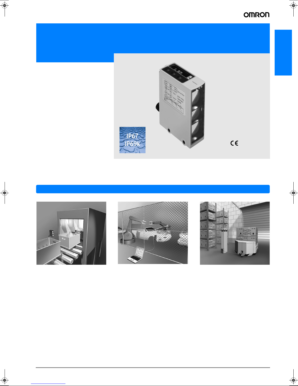
Harsh environment long distance photoelectric Sensor in metal housing
E3NT
• 4 Diffuse reflective E3NT-L application
optimized models:
• Extra long distance type for setting
distances up to 3 m
• Window heating type for low tem-
perature environments
• Analog output type for distance in-
formation
• Fast response type for high speed
detection and counting
• Retro reflective E3NT-R models with
sensing distance up to 16 m
• Two programmable outputs for ’window teaching’
• Double triangulation for stable detection of reflective objects
• IP67 and IP69k for highest resistance
in wet environments
E3NT
Condensation in often cleaned environments or due to rapid temperature
changes is prevented by the completely sealed housing of the E3NT and the
optional window heating.
Application
With the optic link, the sensor can be
remotely set and checked while it is operating in an area where access is restricted.
This robust sensor is ideal for operation in harshest environments.
A-83E3NT
Page 2
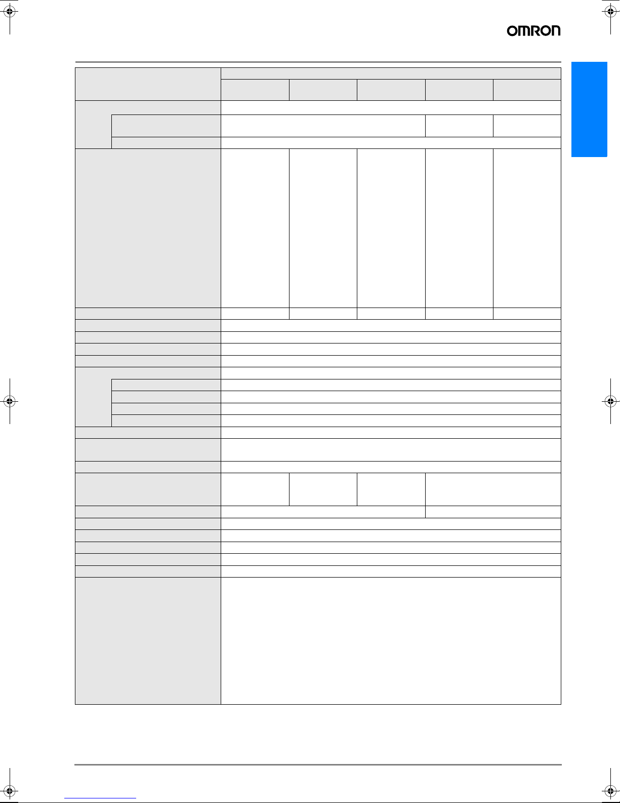
Ordering Information
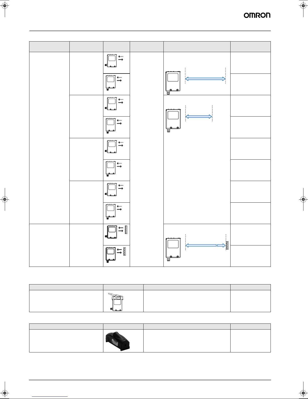
Sensors
Sensing method Type Appearance Connection
Distance setting
Long distance M12 Connector
(BGS/FGS)
Window heating 0.2 m .. 2.0 m E3NT-LH17
Fast response E3NT-L17
method
(5-pole)
Sensing / Setting distance Model
0.2 m .. 3.0 m (90% remission)
E3NT-L17-20
0.2 m .. 2.7 m (6% remission)
200 mm 3,000 mm
E3NT-L37-20
200 mm 2,000 mm
E3NT-LH37
E3NT-L37
Analog and
E3NT-L27
digital output
E3NT-L47
Retro reflective
(with MSR-polarisa-
Long distance 0.2 m .. 16.0 m (with E39-R8) E3NT-R17
200 mm 16,000 mm
tion)
E3NT-R37
Accessories (order separately)
Optical data link
Communication method to sensor Appearance Communication method to PC Model
IR data interface RS232 E3NT-AL232 2M
Laser alignment aid
Max. distance for visible spot Appearance Operation time Model
50 m min. 5 hours with new battery E3NT-AP1
A-84 Standard Photoelectric Sensors
Page 3
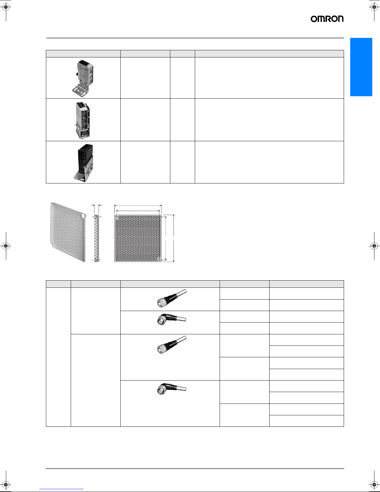
Mounting brackets
for M3
Appearance Model Qty. Remarks
Reflectors
E39-R8
E39-EL1 1 Universal mounting bracket
E3NT
E39-EL2 1 Adapter bracket (for use of the universal mounting bracket for
not matching holes)
E39-EL3 1 Adapter bracket replacing E3N with E3NT
9
100
92
92
100
ffor M3
Sensor I/O connectors
Size Cable type Shape Cable length Model
M12 Standard 5-pole 2m XS2F-D521-DG0-A
Straight
5m XS2F-D521-GG0-A
L-shape
2m XS2F-D522-DG0-A
5m XS2F-D522-GG0-A
Standard 4-pole
(Pin 5 not connected)
Straight
2m 934 401 101 (PVC)
934 401 201 (PUR)
5m 934 401 100 (PVC)
934 401 200 (PUR)
L-shape
2m 934 402 102 (PVC)
934 402 201 (PUR)
5m 934 402 100 (PVC)
934 402 200 (PUR)
A-85E3NT
Page 4
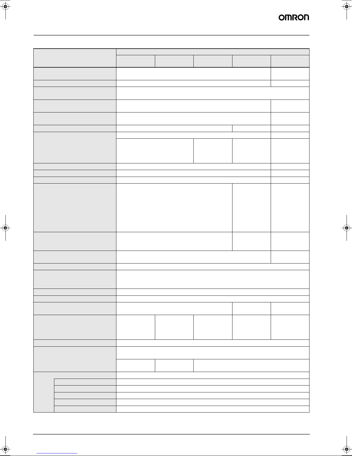
Rating/performance
Sensors
Item Model
E3NT-L17
E3NT-L37
Sensor type Diffuse reflective sensor with background suppression respectively
foreground suppression
Signal evaluation Double triangulation method Polarization
Configuration By push button on the sensor or with a PC connected via the optical data link E3NT-AL232
2m
Operating modes Background suppression, foreground suppression, background and
foreground suppression (2-point window evaluation)
Light source Infrared LED 850 - 880 nm Red LED
Rated sensing distance 2 m 3 m 16 m
Setting distance Sr Distance – setting possible between ---
0.2 ... 2.0 m (90 % remission)
0.2 ...1.7 m (6 % remission)
Standard measured object Kodak gray card 90% (white), size: 200 x 200 mm --Blind zone < 0.1 m < 0.15 m
Black/white error (6%/90%) < 15 % of setting distance Sr --Hysteresis (typical) < 5 % of setting distance Sr or 4 cm (for white 90 %)
< 10 % of setting distance Sr or 6 cm (for black 6 %)
Repetition accuracy < 5 % (of setting distance Sr) or 4 cm < 5 % (of setting
Light spot diameter < 40 mm in the case of Sr = 2 m app. 100 mm*1
Minimum object size > 40 mm
Ambient light immunity to
EN 60947-5-2:
Utilization category to EN 60947-5-2 DC 12
Rated operating voltage + 24 V DC, polarized
Operating voltage range + 10 ... + 30 V DC + 11 ...
Current consumption < 90 mA
Power-on delay < 300 ms
Input – / Output – pins Pin 2 = Input (In 2) or output (Out 2), depending on configuration
Digital Outputs User set functions (e.g. switching output, alarm output, ...)
Output circuit User set PNP (open collector), NPN (open collector) or complementary (push-pull)
Output current max. 100 mA
Voltage drop < 2.0 V
Residual current < 100 µA
Circuit protection Reversed power supply, overload, short-circuit (pulsed)
Halogen lamps (100-120 Hz > 10,000 lux
Fluorescent lamps (30 kHz) > 5,000 lux
Energy saving lamps > 2,000 lux
(display off)
< 110 mA
(display on)
Pin 4 = Output (Out 1)
Pin 5 = Input
(In 1)
E3NT-L27
E3NT-L47
< 100 mA
(display off)
< 120 mA
(display on)
Pin 5 = Analog
output
E3NT-LH17
E3NT-LH37
0.2 ... 2.0 m
(90 % remission)
0.2 ...1.4 m
(6 % remission)
< 220 mA with
front pane heating
Pin5 = Input (In1)
E3NT-L@7-20 E3NT-R
Retroreflective
sensor
---
660 nm
0.2 ... 3.0 m
(90 % remission)
0.2 ...2.7 m
(6% remission)
< 10 % of setting
distance Sr or
10 cm (for
white)
< 15 % of setting
distance Sr or
10 cm (for
black)
distance Sr) or
10 cm
+30VDC
< 110 mA
(display off)
< 130 mA
(display on)
0.2 ... 16.0 m
---
---
at 10 m
+ 10 ...
+30VDC
< 80 mA
(display off)
< 110 mA
(display on)
A-86 Standard Photoelectric Sensors
Page 5
Item Model
E3NT-L17
E3NT-L37
E3NT-L27
E3NT-L47
E3NT-LH17
E3NT-LH37
E3NT-L@7-20 E3NT-R
Inputs User set functions (e.g. teach-in, trigger, test, ...)
supply
Voltage input
+10 V ... U
supply
Input circuit Voltage input +10 V ... U
Voltage input
supply
+11 V ... U
Input pulse duration min. 1 ms
Analog Output Current output
3..21mA:
• 3 mA correspond to
distance < 0.2
m
• 4 ... 20 mA
correspond to
distance 0.2
m ... 2.0 m
• 21 mA correspond
to distance >
2.0 m
(or no object)
Switch-on/off time (TON / T
) ≤2.5 ms ≤5 ms ≤2.5 ms ≤20 ms ≤2.0 ms
OFF
Insulation resistance 20 MΩat 500 V DC
Insulation voltage strength 1,0 kV AC, 50/60 Hz (1 min)
Impulse strength (insulation) 1,5 kV
Dimensions (length x width x depth) 85 x 27 x 65 mm
Materials
Housing
Powder-coated aluminum, sea-water resistant, 231 GD AlSi12 (Cu) (standard version)
Front pane Glass
Keyboard HTV silicone
Seals RTV silicone
Housing color Grey, RAL 7030
Assembly Screw fastening by way of four M5 threads and two M5 through holes or with universal
mounting bracket (order separately)
Connection M12 connector, 5-pole (piercing)
Ambient temperature range - 25 °C ... +
55 °C
- 10 °C ... +
55 °C
- 40 °C ... +
55 °C
- 25 °C ... + 55 °C
(analog output)
Storage temperature range - 40 °C ... + 60 °C - 40 °C ... + 70 °C
Permissible relative humidity 35 % ... 95 %, no condensation
Enclosure rating IP 67 (EN 60529), IP 69k (DIN 40050)
Protection class II (50 V DC)
Vibration resistance ± 1.5 mm, 1 h , 10 - 70 Hz (IEC 68-2-6)
Shock resistance 300 m/s² (IEC 68-2-27)
User set parameters - Mode
- Output function
- Teach/set switching points
- Output switching
- Function on connector pin 2 and 5
- Switch-on and off delay
- Type of switch-off time function
- Type of display on the sensor
- Keyboard lock
- Energy saving mode
- Display direction
- Reset to factory defaults
*1.
see diagramm
E3NT
A-87E3NT
Page 6

Accessories
E3NT-AL 232 2 M
Item
Dimensions (length x width x depth) 29.5 x 72.9 x 26.4 mm
Housing material ABS and PMMA (IR transparent)
Housing colour Black, RAL 9005
Assembly Snap mounting on sensor
Connection 2 m connecting cable with 9-pole sub-D connector
Ambient temperature range - 10 °C ... + 50 °C
Storage temperature range - 40 °C ... + 60 °C
Permission relative humidity 35% ... 85%, no condensation
Degreee of protection to
EN 60529 / IEC 529
Emitted light IR communication element 880 nm
Rated operating voltage Via RS 232 interface from PC
Current consumption 6 mA
E3NT-AP1
Item
Supply voltage 3 V DC
Battery type Button battery Ø 11.6 mm, thickness: 5.4 mm, 3 Vm, type: CR1/3N
Ambient temperature range + 10 °C ... + 40 °C
Storage temperature range - 40 °C ... + 60 °C (with no icing or condensation)
Ambient humidity Operation and storage: 35% ... 85% (with no icing or condensation)
Ambient environment No corrosive gases
Operation time period min. 5 hours operation with 1 new battery
Degree of protection IP20 (EN 60529)
Case material Case: ABS/PC
Weight Approx. 42 g
Accessories: 1 Instruction sheet, 1 battery type CR1/3N
Max. distance for a visible beam spot about 50 m (depending on the ambient light and surface conditions)
Laser beam power < 1 mW
Laser class Laser Class II
IP 54
Base plate: Aluminium
A-88 Standard Photoelectric Sensors
Page 7

Characteristic data (typical)
E3NT-L17/L37 and E3NT-LH17/LH37
Operating range
(90% remission)
30
20
10
0
-10
Object position X (mm)
-20
-30
0 500 1000 1500 2000 2500
Distance Z (mm)
E3NT-L27/L47
Analog output current
(90% remission)
24
20
16
12
8
current I (mA)
4
0
0 500 1000 1500 2000 2500
Distance Z (mm)
Object
E3NT
Z
X
Black/White - Error
(6% - 90% remission)
20
15
10
5
0
Black/White-error (%)
-5
-10
0 500 1000 1500 2000 2500
Distance Z (mm)
Hysteresis
15
10
5
Object
Hysteresis (%)
E3NT
Z
X
0
Object
E3NT
Z
X
0 500 1000 1500 2000 2500
black object
white object
Distance Z (mm)
E3NT
E3NT-L17-20 and E3NT-L37-20
Parallel Operating range Black/White - Error
(6% - 90% remission, typical)
30
20
10
0
-10
Object position X (mm)
-20
-30
0 1500 3000
Distance Z (mm)
Object
E3NT
X
4%
3%
2%
1%
0%
-1%
-2%
Black/White-error (%)
Z
-3%
-4%
0 3000
E3NT-R
Spotsize
200
100
Spotsize (mm)
0
501015
Distance Z (mm)
Hysteresis (typical)
12%
10%
8%
6%
4%
Hystersis (%)
2%
0%
0 3000
Black
White
A-89E3NT
Page 8

Circuit diagram
A
O
Output
Push-pull output circuit
(Out1 at pin 4 / Out2 at pin 2)
Load connection
PNP NPN Analog
Internal circuit
T
T
E3NT
PNP
NPN
+ U
1
S
+ U
1
1
1
+ U
B
Out1
4
Out2
(2)
0 V
3
Out1
Out2
0 V
4
2
L
1
L
2
3
+ U
Out1
Out2
0 V
B
L
1
L
2
4
2
3
B
n Out 5
0 V 3
+
I
-
When use is made of the PNP or NPN output circuit, the output circuit that is not selected is deactivated. When used as a complementary output, NPN or PNP outputs act in antiphase as the switch state changes.
Input
In2 at pin 2 In1 at pin 5
(not available for analogue output models)
E3NT
Internal circuit
+ U
S
In2 2
0 V 3
E3NT
1
Internal circuit
+ U
1
S
In1 5
0 V 3
The sensor inputs are realised in positive logic and detect a positive voltage level of more than 1 ms duration as a valid signal if
the voltage level is between 10 V and the power supply voltage.
Connectors
Class Wire jacket
color
Connector
pin no.
Application
For DC Brown 1 Power
supply (+V)
White 2 Output or Input
Out2 / In2
Blue 3 Power
supply (0V)
Black 4 Output Out1
AEDC
B
Wire
1
2
3
4
colors
Brown
White
Blue
Black
Grey 5* Analog Output or
Input In1
* Not connected for standard 4-pole connectors
A-90 Standard Photoelectric Sensors
Page 9

Nomenclature
LED display Status LED optical IR element for data communication
Red LED
(Output 2)
Yellow LED
(Output 1)
Alignment aid
ENTERIncrementDecrement
LED display The distance from the measured object and the names of the menu levels during set-up of the sensor are
displayed by the 4-digit 7-segment LED display.
The display appears as red digits or letters.
If the sensor is set to a bar chart display, the distance from the measured object is displayed as a green
LED bar chart.
LED The switching status and the stability of the two outputs are signalled as follows by two LEDs, visible from
the top and the front of the sensor:
Yellow LED (Output 1) ON Object stably detected
Blinking Object not stable detected
OFF No object within range
Red LED (Output 2) ON Object stably detected
Blinking Object not stable detected
OFF No object within range
Status LED ON Set-up menu selected
Blinking Menu level with change of setting distance
OFF RUN (normal) mode
E3NT
Operation
Setting the switching points
The switching points can either be user set (Teach-in mode)
with a measured object positioned at the corresponding distance or can be set using the setting input, for remote setting.
For each output of the sensor (up to two), up to two switching
points can be user set.
Only one switching point is active in the foreground and background suppression modes.
For the 2-point window evaluation mode, two switching points
must be set.
Teaching the switching points in the normal mode
The sensor is set at the factory for both outputs to BGS, light
on.
1. Place the target object in front of the sensor at the desired
position.
2. Teach the switching point for output 1:
• Beginning with the key, press it simultaneously with the
ENTER key. Threshold level is obtained and the output/
LED is updated. Status LED is blinking.
• Using the / keys an adjustment of the switching point is
≈
possible. The output/LED is updated immediately.
• Pressing the ENTER key for more than 2 seconds or after 2 minutes without any activation of the keys, the sensor
returns to normal operation. The status LED is turned off.
3. Teach the switching point for Output 2:
• Beginning with the key, press it simultaneously with the
ENTER key.
≈
Main menu structure
Normal
operation
Enter 2 s
Enter 2 s
tch
팫 / 팬 팫 / 팬
Menu path
TEACH
Switching
point
settings
Enter 2 s Enter 2 s
5Et
Menu path
SET
Function
settings
0Pt
팫 / 팬
Menu path
OPTIONS
Additional
settings
Status LED
When the ENTER key is pressed for 2 seconds, the sensor
switches from the normal mode to the TEACH menu path.
The sensor switches to each next menu path when the ENTER key is repeatedly pressed for 2 seconds. In the menu
paths, the required parameters can be selected by pressing
≈
and keys.
To skip a menu path, you can also press the ENTER key
for 4 seconds.
[ENTER] Press the ENTER key < 1 second
[ENTER 2s] Press the ENTER key > 2 seconds.
OFFON
A-91E3NT
Page 10

TEACH menu
Menu items
Teaching
Switching point A
Output 1
Teaching
Switching point B
Output 1
Teaching
Switching point C
Output 2
Teaching
Switching point D
Output 2
2.)
2.)
Normal
operation
Enter 2 s
tch
tc-A
1.)
tc-b
tc-C
1.)
tc-d
Enter 2 s
Enter
Enter
Enter
Enter
Switch. point A
Switch. point B
Switch. point C
Switch. point D
Status LED is blinking
Output 1
teached
Output 1
teached
Output 2
teached
Output 2
teached
Status LED
Status LED
is blinking
is blinking
Set
Switch. point A
in m
with 팫 / 팬
Set
Switch. point B
in m
with 팫 / 팬
Set
Switch. point C
in m
with 팫 / 팬
Set
Switch. point D
in m
with 팫 / 팬
Enter
Enter
Enter
Enter
Setting of
Switching point A
Output 1
0 ... 2.5 m
in 1 cm increments
Setting of
Switching point B
Output 1
0 ... 2.5 m
in 1 cm increments
Setting of
Switching point C
Output 2
0 ... 2.5 m
in 1 cm increments
Setting of
Switching point D
Output 2
0 ... 2.5 m
in 1 cm increments
2.)
2.)
Ad-A
1.)
Ad-b
Ad-C
1.)
Ad-d
Enter 2 s
Enter Enter
Enter Enter
Enter Enter
Enter Enter
Set
Switch. point A
in m
with 팫 / 팬
Set
Switch. point B
in m
with 팫 / 팬
Set
Switch. point C
in m
with 팫 / 팬
Set
Switch. point D
in m
with 팫 / 팬
Output 1
Switch. point A
set
Output 1
Switch. point B
set
Output 2
Switch. point C
set
Output 2
Switch. point D
set
5Et
1.) In the 2-point window evaluation mode, two switching points (A/B and C/D) can be set for each output. In the foreground and background suppression modes, only
one switching point (A and C) can be set for each output. Then, only these switching points, A and C, can be set in the TEACH menu path. B and D switching points
are not available.
2.) If connector pin 2 is set as an input, only the switching points for Output 1 can be set.
A-92 Standard Photoelectric Sensors
Page 11

SET menu
Menu items
Function
Output 1
Function
1.)
Output 2
Switch-on
2.) 5.)
delay
Output 1
0 ... 9999 ms
in 1 ms decrements
Switch-off
2.) 3.)
delay
Output 1
0 ... 9999 ms
in 1 ms decrements
Normal
operation
Enter 2 s
Enter 2 s
5Et
0ut1
0ut2
tr-1
tF-1
Enter 2 s
Background
Set time
in ms
with팫 / 팬
Set time
in ms
with팫 / 팬
suppression
Foreground
suppression
Window
evaluation
Background
suppression
Foreground
suppression
Window
evaluation
Select
Enter
function
with
팫 / 팬
Select
Enter
function
with
팫 / 팬
Enter Enter
Enter Enter
b65
Enter
F65
2-P
b65
Enter
F65
2-P
Switch-on
delay
Output 1
parameterised
Switch-off
delay
Output 1
parameterised
Select
function
with
팫 / 팬
Select
function
with
팫 / 팬
light-on
dark-on
light-on
dark-on
L-on
d-on
L-on
d-on
E3NT
Enter
Enter
Switch-on
2.) 5.)
delay
1.)
Output 2
0 ... 9999 ms
in 1 ms decrements
Switch-off
2.) 3.)
delay
1.)
Output 2
0 ... 9999 ms
in 1 ms decrements
Distance
display
Key
4.)
lock
Enter 2 s
tr-2
tF-2
di5P
L0CH
Enter Enter
Enter
Enter Enter
Set time
in ms
with팫 / 팬
Set time
in ms
with팫 / 팬
Select
function
with
팫 / 팬
Select
function
with
팫 / 팬
Absolute
Bar
graph
Locking
OFF
Locking
ON
Enter
Switch-on
delay
Output 2
parameterised
Switch-off
delay
Output 2
parameterised
Ab5
bAr
oFF
EnterEnter
on
0Pt
1.) If connector pin 2 is set as an input, the switch-on/off delay function canonly be set for Output 1. A second switching output is not available.
2.) If the switch-on/off delay is off in the OPTIONS menu path, the switch-on/off delay parameters do not appear in the SET menu path.
3.) The outputs behave differently depending on the switch-off delay functionthat is set in the OPTIONS menu path.
4.) The key lock becomes active again when no keys have been pressed for approx. 5 minutes.
The key lock can be temporarily cancelled by pressing the and keys for 4 seconds.
5.) The On-delay-setting tr-1 or tr-2 are only available if the switch-on/off de-lay in the OPTIONS menu path is set to %n-1.
≈
A-93E3NT
Page 12

OPTIONS menu
Menu items
Function
Connector pin 2
Function
Connector pin 5
Function
Switch-on /
switch-off
delay
Output 1
Function
Switch-on /
switch-off
delay
1.)
Output 2
Normal
operation
Enter 2 s
Enter 2 s
Enter 2 s
0pt
pin2
pin5
ti-1
ti-2
Enter 2 s
Enter
Enter
Enter
Enter
Select
function
with
/
Select
function
with
/
Select
function
with
/
Select
function
with
/
in
,ut
Enter
Enter
tcha
tchb
tchc
tchd
te5t
tri6
,ff
Input
Output
Teach input A
Teach input B
Teach input C
Teach input D
Test input
Trigger input
Input off
Switch-on / switch-off
delay OFF
Switch-on / switch-off
delay NORMAL
Switch-off delay
Minimum pulse width
Switch-off delay
Single pulse
Switch-on / switch-off
delay OFF
Switch-on / switch-off
delay NORMAL
Switch-off delay
Minimum pulse width
Switch-off delay
Single pulse
Enter
3.)
,ff
,n-1
,n-2
,n-3
,ff
,n-1
,n-2
,n-3
Enter
Enter
Select
function
with
/
Select
function
with
/
Teach input A
Teach input B
Test input
Trigger input
Switching
output
Alarm output
tcha
tchb
te5t
tri6
,ut2
alar
Enter
Enter
Select
Energy saving mode
2.)
ECO
Turn display
Output
stage
Reset
to
Works default
Enter 2 s
Normal
operation
1.) If connector pin 2 is set as an input, the type of switch-on/off delay option can only be set for Output 1.
2.) If the ECO energy saving mode is on, the display is switched off if no keys are pressed for about 5 minutes. The display is switched on again when any key is
pressed.
3.) Firmware 1.10 and higher
ec0
flip
n-p
r5et
Enter
Enter
Enter
Enter
function
with
Select
function
with
Select
function
with
/
Select
function
with
/
/
/
ECO-Mode
ON
ECO-Mode
OFF
,ff
,n
Plus
switching
Minus
switching
Complementary
ye5
n,
,n
,ff
pnp
npn
c,pl
Enter
Enter
Enter
Enter
Enter
d,ne
Enter
A-94 Standard Photoelectric Sensors
Page 13

SET menu E3NT-R
Menu items
Function of
switching output
Switch-on
delay of switching
output in ms
(regarding to setting
of delay function in
OPT menu)
Switch-on
delay of switching
output in ms
(regarding to setting
of delay function in
OPT menu)
Normal
operation
Enter 2 s
Enter
Select
function
with
/
Set time
in ms
with
/
Set time
in ms
with
/
/
light-on
dark-on
EnterEnter
EnterEnter
EnterEnter
Switch-on delay
parameterized
Switch-off delay
parameterized
E3NT
Enter
minimum pulse
width / constant
pulse width of
switching output in
ms (regarding to
setting of delay
function in OPT
menu)
Key lock
Enter 2s
Set time
in ms
with
/
Select
function
with
/
EnterEnter
Locking
OFF
Locking
ON
Minimum pulse
width / constant
pulse width
parameterized
EnterEnter
A-95E3NT
Page 14

OPTIONS menu E3NT-R
Menu items
Function
connector pin 2
Function
connector pin 5
Switching output
delay functions
Energy saving
mode ECO
Normal
operation
Enter 2 s
Enter 2 s
Enter
Enter
Enter
Enter
Select
function
with
/
Select
function
with
/
Select
function
with
Select
function
with
/
/
Input
Output
OFF
Test input
Delay function
OFF
Switch-on / switch off
delay
Switch-off delay
minimum pulse width
constant pulse width
ECO-mode
OFF
ECO-mode
ON
Enter
Enter
Enter
Enter
Enter
Select
function
with
Select
function
with
Test input
/
Alarm output
/
Enter
Enter
Turn display
Output stage
Front window
heating (optional)
Reset to
works default
Enter 2 s
Normal
operation
Enter
Enter
Enter
Enter
Select
function
with
/
Select
function
with
/
Select
function
with
/
Select
function
with
/
Display turn
OFF
Display turn
ON
Plus
switching
Minus
switching
Complementary
Front window
heating OFF
Front window
heating ON
Front window
heating AUTO
Enter
Enter
Enter
Enter
Enter
A-96 Standard Photoelectric Sensors
Page 15

Dimensions
Sensors
E3NT-L17
E3NT-L27
E3NT-LH17
E3NT-L37
E3NT-L47
E3NT-LH37
14 33.4
14
27
14
M5 (4x)
M12
27
14 33.4
M5 (4x)
E3NT
88.7
M5 (2x)
14.3
Accessoires (order separately)
Optical data link
E3NT-AL232 2m
30
30 23.1 15.7
65.1
4.7
cable 2 m
88.7
4.7
M5 (2x)
65.1
15.2
12.1
23.130
M12
27
68,9
Sub-D connector 9-pole, female
A-97E3NT
Page 16

Laser alignment aid
E3NT-AP1
30
27
68,9
Universal mounting bracket
E39-EL1
R
5
x
7
31
108
30
15˚
.4
8
2
R
x 2
5
22.
R
R
46
28˚
˚
0
5
7
0˚
3
11
26
30
39.5
5
7
10
2
.6
0
8
R
R
3
0
ø 5.3±0.1
60
14
2
5
2.5
˚
17.5
ø6.
8.5
3
±
0
.
1
1
10.5
25
R
R
82.74
84.5
38±1
74
95
120±1
7
92
4
15
55.5
ø4.2
±
0.1
R
±0.1
30
28
0˚
1
ø4.2
90
˚
Rx
˚
.5
9
0˚
material: stainless steel 1.4305
Adapter bracket
E39-EL2
7
43.4
7.8
ø6.3
material: stainless steel 1.4305
10
A-98 Standard Photoelectric Sensors
45
3
22.5
R
ø5.2
90˚
Rx
15
2
20
20.3
Page 17

Replacement bracket for E3N with E3NT
E39-EL3
6
6.5
12
70
58
35
Ø
4 x
5˚
R60
73
30
10˚
12x
±0.3
14
14
Ø
5.2
±0.3
2
R
4x
50
15
6
10˚
30
21
7
10˚
90˚
material: stainless steel 1.4305
3
E3NT
6
R
A-99E3NT
Page 18

Precautions
Mounting Directions
Sensor assembly
Contrary to sensors with single triangulation, E3NT with double triangulation, allows the measured object's direction of
motion to be in all three directions. Thus, the rotatory position
of the sensor about its optical axis can be chosen freely.
Sensor's assembly direction
As far as possible, the sensor's optical surface should be
aligned parallel to the surface of the measured object.
90˚
detection object
90˚
If the measured object has a glossy, reflecting surface, the
sensor's optical system should be tilted by 5 … 10° in relation
to the surface of the measured object.
If the light spot is not completely on the same plane as the target object (minimum object size) the distance is not determined and malfunction can occur. If necessary a trigger signal
or timer function has to be applied.
The sensor must be fitted so that:
• It is correctly aligned before it is adjusted
• It is protected as far as possible against vibration and shock
• It is protected as far as possible against extraneous incident
light
• It is protected as far as possible against damage and soiling
• Electrical connection is possible
• It is as accessible as far as possible for maintenance work
• Operation of the push buttons is possible
• The display is visible.
5 … 10˚˚
90˚
detection object
If there is a reflecting surface in parallel with the sensor's optical axis, this might lead to unstable switching states.
Therefore, reflecting objects within the sensor's optical axis
should be avoided.
If this should not be possible, the reflecting surface should not
be parallel to the sensor's optical axis, but should be rotated
by at least 10°.
Mirror-like objects can cause malfunction inside and outside
the sensing range. Avoid mirror-like objects in or close to the
optical axis.
Inspection and Maintenance
Cleaning
Do not use any scratching or abrasive cleaning materials. The
protective pane of the optical system might get damaged.
The sensor requires no maintenance.
Remove dirt build up from the optical system and the display
at regular intervals only with a soft, non abrasive fabric. Residual dirt may have influence on the switching point and display accuracy.
ALL DIMENSIONS SHOWN ARE IN MILLIMETERS.
To convert millimeters into inches, multiply by 0.03937. To convert grams into ounces, multiply by 0.03527.
Cat. No. E332-E2-02-X
In the interest of product improvement, specifications are subject to change without notice.
A-100 Standard Photoelectric Sensors
 Loading...