

Page 1

Cat. No. E30E-EN-01A
Diffuse Reflective Sensor
E3NT-L
Photoelectric Sensor
OPERATION MANUAL
Page 2

TABLE OF CONTENTS
SECTION 1
Important Precautions . . . . . . . . . . . . . . . . . . . . . . . . . . . 5
1-1 Using the operating instructions . . . . . . . . . . . . . . . . . . . . . . . . . . . . . . . . . . . . . . . 6
1-2 Use in accordance with the intended purpose. . . . . . . . . . . . . . . . . . . . . . . . . . . . . 6
1-3 Use that is not in accordance with the intended purpose . . . . . . . . . . . . . . . . . . . . 6
1-4 Electromagnetic compatibility (EMC) . . . . . . . . . . . . . . . . . . . . . . . . . . . . . . . . . . 6
1-5 Warranty and liability . . . . . . . . . . . . . . . . . . . . . . . . . . . . . . . . . . . . . . . . . . . . . . . 7
1-6 Key to symbols . . . . . . . . . . . . . . . . . . . . . . . . . . . . . . . . . . . . . . . . . . . . . . . . . . . . 7
1-7 Abbreviations . . . . . . . . . . . . . . . . . . . . . . . . . . . . . . . . . . . . . . . . . . . . . . . . . . . . . 7
SECTION 2
Safety Notes . . . . . . . . . . . . . . . . . . . . . . . . . . . . . . . . . . . . 9
2-1 Safety notes. . . . . . . . . . . . . . . . . . . . . . . . . . . . . . . . . . . . . . . . . . . . . . . . . . . . . . . 10
SECTION 3
Specification. . . . . . . . . . . . . . . . . . . . . . . . . . . . . . . . . . . . 11
3-1 Diffuse reflective sensor . . . . . . . . . . . . . . . . . . . . . . . . . . . . . . . . . . . . . . . . . . . . . 12
3-2 Optical data link E3NT-AL232 (order separately) . . . . . . . . . . . . . . . . . . . . . . . . . 17
3-3 Dimensions . . . . . . . . . . . . . . . . . . . . . . . . . . . . . . . . . . . . . . . . . . . . . . . . . . . . . . . 18
SECTION 4
Function . . . . . . . . . . . . . . . . . . . . . . . . . . . . . . . . . . . . . . . 23
4-1 Functions. . . . . . . . . . . . . . . . . . . . . . . . . . . . . . . . . . . . . . . . . . . . . . . . . . . . . . . . . 24
4-2 Display and operator controls . . . . . . . . . . . . . . . . . . . . . . . . . . . . . . . . . . . . . . . . . 26
4-3 User set parameters . . . . . . . . . . . . . . . . . . . . . . . . . . . . . . . . . . . . . . . . . . . . . . . . . 27
4-4 Inputs/Outputs. . . . . . . . . . . . . . . . . . . . . . . . . . . . . . . . . . . . . . . . . . . . . . . . . . . . . 33
SECTION 5
Transport . . . . . . . . . . . . . . . . . . . . . . . . . . . . . . . . . . . . . . 35
5-1 Packaging / Transportation damage . . . . . . . . . . . . . . . . . . . . . . . . . . . . . . . . . . . . 36
5-2 Storage . . . . . . . . . . . . . . . . . . . . . . . . . . . . . . . . . . . . . . . . . . . . . . . . . . . . . . . . . . 36
5-3 Scope of delivery. . . . . . . . . . . . . . . . . . . . . . . . . . . . . . . . . . . . . . . . . . . . . . . . . . . 36
SECTION 6
Assembly . . . . . . . . . . . . . . . . . . . . . . . . . . . . . . . . . . . . . . 37
6-1 Safety notes. . . . . . . . . . . . . . . . . . . . . . . . . . . . . . . . . . . . . . . . . . . . . . . . . . . . . . . 38
6-2 Sensor assembly . . . . . . . . . . . . . . . . . . . . . . . . . . . . . . . . . . . . . . . . . . . . . . . . . . . 38
3
Page 3

TABLE OF CONTENTS
SECTION 7
Electrical Connection . . . . . . . . . . . . . . . . . . . . . . . . . . . . 41
7-1 Safety notes . . . . . . . . . . . . . . . . . . . . . . . . . . . . . . . . . . . . . . . . . . . . . . . . . . . . . . 42
7-2 Establishing electrical connection . . . . . . . . . . . . . . . . . . . . . . . . . . . . . . . . . . . . . 42
7-3 Connection diagrams . . . . . . . . . . . . . . . . . . . . . . . . . . . . . . . . . . . . . . . . . . . . . . . 43
7-4 Connection in line with EMC requirements . . . . . . . . . . . . . . . . . . . . . . . . . . . . . 45
SECTION 8
Setting into Operation. . . . . . . . . . . . . . . . . . . . . . . . . . . . 47
8-1 Safety notes . . . . . . . . . . . . . . . . . . . . . . . . . . . . . . . . . . . . . . . . . . . . . . . . . . . . . . 48
8-2 Switching on the operating voltage . . . . . . . . . . . . . . . . . . . . . . . . . . . . . . . . . . . . 48
8-3 Aligning the sensor . . . . . . . . . . . . . . . . . . . . . . . . . . . . . . . . . . . . . . . . . . . . . . . . 49
8-4 Setting the switching points. . . . . . . . . . . . . . . . . . . . . . . . . . . . . . . . . . . . . . . . . . 50
SECTION 9
Sensor Set-up . . . . . . . . . . . . . . . . . . . . . . . . . . . . . . . . . . . 51
9-1 Setting the sensor using the push buttons . . . . . . . . . . . . . . . . . . . . . . . . . . . . . . . 52
9-2 Setting the sensor with a PC . . . . . . . . . . . . . . . . . . . . . . . . . . . . . . . . . . . . . . . . . 60
SECTION 10
Maintenance and Repair. . . . . . . . . . . . . . . . . . . . . . . . . . 61
10-1 Maintenance. . . . . . . . . . . . . . . . . . . . . . . . . . . . . . . . . . . . . . . . . . . . . . . . . . . . . . 62
10-2 Repair. . . . . . . . . . . . . . . . . . . . . . . . . . . . . . . . . . . . . . . . . . . . . . . . . . . . . . . . . . . 62
SECTION 11
Accessories and Parts . . . . . . . . . . . . . . . . . . . . . . . . . . . . 63
11-1 Accessories and parts. . . . . . . . . . . . . . . . . . . . . . . . . . . . . . . . . . . . . . . . . . . . . . . 64
SECTION 12
Appendix . . . . . . . . . . . . . . . . . . . . . . . . . . . . . . . . . . . . . . 65
12-1 Error messages. . . . . . . . . . . . . . . . . . . . . . . . . . . . . . . . . . . . . . . . . . . . . . . . . . . . 66
12-2 Factory default settings . . . . . . . . . . . . . . . . . . . . . . . . . . . . . . . . . . . . . . . . . . . . . 67
4
Page 4

Important Precautions
1-1 Using the operating instructions . . . . . . . . . . . . . . . . . . . . . . . . . . . . . . . . . . . 6
1-2 Use in accordance with the intended purpose. . . . . . . . . . . . . . . . . . . . . . . . . 6
1-3 Use that is not in accordance with the intended purpose . . . . . . . . . . . . . . . . 6
1-4 Electromagnetic compatibility (EMC) . . . . . . . . . . . . . . . . . . . . . . . . . . . . . . 6
1-5 Warranty and liability . . . . . . . . . . . . . . . . . . . . . . . . . . . . . . . . . . . . . . . . . . . 7
1-6 Key to symbols . . . . . . . . . . . . . . . . . . . . . . . . . . . . . . . . . . . . . . . . . . . . . . . . 7
1-7 Abbreviations . . . . . . . . . . . . . . . . . . . . . . . . . . . . . . . . . . . . . . . . . . . . . . . . . 7
SECTION 1
5
Page 5

Using the operating instructions
1-1 Using the operating instructions
These operating instructions refer exclusively to diffuse reflective sensors in
the E3NT type series. They contain the most important notes for operating the
sensor in line with safety requirements.
The operating instructions must always be close at hand and accessible at all
times, and must be kept together with the higher-level machine installation.
The contents of these operating instructions must be read and understood,
and all its points must be followed by everyone who is responsible for machine
planning, assembly and operation. This particularly applies to the safety
notes.
Observance of the safety notes will help to avoid accidents, malfunctions and
faults.
1-2 Use in accordance with the intended purpose
Diffuse reflective sensors in the E3NT type series are always operated as part
of a higher-level overall system, e.g. a machine installation.
They may only be used as optical sensors to check the presence of objects
within a machine installation with a higher-level control system.
Any other use, or any use exceeding this scope, is not permitted.
Use in accordance with the intended purpose also includes observance of the
operating instructions and keeping to the inspection and maintenance specifications in accordance with the system documentation.
Section 1-1
1-3 Use that is not in accordance with the intended purpose
Diffuse reflective sensors in the E3NT type series must not be used as safety
components within the scope of the EU machine guideline.
Its use in applications in which the safety of persons depends on functioning
of the sensor is not permissible!
1-4 Electromagnetic compatibility (EMC)
Diffuse reflective sensors in the E3NT type series are built to conform to the
following standards:
• EN 60947-5-2 Low-voltage switch gear - Part 5-2:
Control devices and switching elements: proximity switches
• EN 50081-2/-1Basic interference emission standard
Industrial area/small establishments
• EN 61000-6-2 Basic interference immunity standard
Industrial area
6
Page 6

Warranty and liability
1-5 Warranty and liability
Our Terms and Conditions of Delivery and Payment fundamentally apply.
These are available to the owner at the latest as from conclusion of a contract.
Warranty and liability claims for personal injury and property damage are
ruled out if they are attributable to one or several of the following causes:
• Use of the sensor that is not in accordance with its intended purpose
• Improper assembly, commissioning and maintenance of the sensor
• Failure to observe the notes in the operating instructions in relation to
transport, storage, assembly, commissioning and maintenance of the
sensor
• Unauthorised structural changes to the sensor
• Repairs carried out improperly
• Disasters resulting from the influence of foreign bodies and acts of God.
Section 1-5
1-6 Key to symbols
The following symbols are used in these operating instructions:
1-7 Abbreviations
The following abbreviations are used in these operating instructions:
Important information
Risk of damage to the machine or material
Risk of injury to life and limb in general
• BGS BackGround Suppression
• FGS ForeGround Suppression
• IR InfraRed
• PC Personal Computer
7
Page 7

Abbreviations
Section 1-7
8
Page 8

2-1 Safety notes. . . . . . . . . . . . . . . . . . . . . . . . . . . . . . . . . . . . . . . . . . . . . . . . . . . 10
SECTION 2
Safety Notes
9
Page 9

Safety notes
2-1 Safety notes
Section 2-1
The diffuse reflective sensors belonging to the E3NT type series may
only be used as described in these operating instructions.
They may only be operated as part of a higher-level overall system,
e.g. a machine installation.
During machine planning and the use of diffuse reflective sensors
belonging to the E3NT type series, the safety and accident prevention
regulations that are specific to use must be observed, e.g.:
•EN 292, Safety of machines, general design principles
•EN 60204, Electrical equipment of machines
Diffuse reflective sensors belonging to the E3NT type series must not
be used as safety components within the scope of the EU Machine
guidelines.
Their use in applications in which the safety of persons depends on
functioning of the sensor is not permissible!
The manufacturer and owner of the higher-level overall system, e.g. of
a machine installation, is responsible for conformity with the national
and international safety and accident prevention regulations that apply
to the special application.
Assembly, electrical connection and maintenance may only be carried
out by instructed, trained and authorised specialist personnel in
accordance with applicable regulations after de-energising the power
supply and switching off the machine.
The machine must be safeguarded against reactivation.
Conversions and changes as well as tampering with the interior of the
sensor, the data link and the alignment tool are forbidden.
The notes contained in these operating instructions, in particular the
chapters entitled Safety notes and Maintenance and repair, must be
integrated into the operating instructions of the higher-level overall system.
10
Page 10

Specification
3-1 Diffuse reflective sensor . . . . . . . . . . . . . . . . . . . . . . . . . . . . . . . . . . . . . . . . . 12
3-1-1 General data . . . . . . . . . . . . . . . . . . . . . . . . . . . . . . . . . . . . . . . . . . . 12
3-1-2 Optical data. . . . . . . . . . . . . . . . . . . . . . . . . . . . . . . . . . . . . . . . . . . . 12
3-1-3 Mechanical data . . . . . . . . . . . . . . . . . . . . . . . . . . . . . . . . . . . . . . . . 13
3-1-4 Electrical data . . . . . . . . . . . . . . . . . . . . . . . . . . . . . . . . . . . . . . . . . . 14
3-1-5 Standards and approvals . . . . . . . . . . . . . . . . . . . . . . . . . . . . . . . . . . 15
3-1-6 Parallel operating range . . . . . . . . . . . . . . . . . . . . . . . . . . . . . . . . . . 16
3-1-7 Black/White-error (6 % / 90 % remission, typical) . . . . . . . . . . . . . 16
3-1-8 Hysteresis (typical). . . . . . . . . . . . . . . . . . . . . . . . . . . . . . . . . . . . . . 16
3-2 Optical data link E3NT-AL232 (order separately) . . . . . . . . . . . . . . . . . . . . . 17
3-3 Dimensions . . . . . . . . . . . . . . . . . . . . . . . . . . . . . . . . . . . . . . . . . . . . . . . . . . . 18
3-3-1 Sensor E3NT-L17 with horizontal connector . . . . . . . . . . . . . . . . . . 18
3-3-2 Sensor E3NT-L37 with vertical connector . . . . . . . . . . . . . . . . . . . . 19
3-3-3 Universal mounting bracket E39-EL1 (order separately). . . . . . . . . 20
3-3-4 Adapter bracket E39-EL2 (order separately) . . . . . . . . . . . . . . . . . . 20
3-3-5 Optical data link E3NT-AL232 2m (order separately) . . . . . . . . . . . 21
SECTION 3
11
Page 11

Diffuse reflective sensor
3-1 Diffuse reflective sensor
3-1-1 General data
Section 3-1
Sensor type E3NT-L@@7 Diffuse reflective sensor with background respectively fore-
Signal evaluation Double triangulation method
Options Window heating, analog output
User settings By push button on the sensor or with a PC connected via the
Operating modes Background suppression, foreground suppression, back-
Optical data link (order separately) Set-up via a PC, real-time analog value output, firmware
ground suppression
optical data link (order separately)
ground and foreground suppression (2-point window evaluation)
update
3-1-2 Optical data
Emitted light Infrared, 850 - 880 nm
Rated sensing distance 2 m
Setting distance, Sr teachable/manual set-up
0.2 ... 2.0 m (90 % remission)
0.2 ...1.7 m (6% remission)
Standard measured object Kodak grey card 90%, 200 x 200 mm
Blind zone < 0.1 m
Black/white error (6%/90%) < 15 % (of setting distance Sr)
Hysteresis < 5 % of setting distance Sr (remission 90 %) or max. 4 cm
< 10 % of setting distance Sr (remission 6 %) or max. 6 cm
(higher value valid)
Repetition accuracy < 5 % (of setting distance Sr) or 4 cm (higher value valid)
Light spot diameter < 40 mm in the case of Sr = 2 m
Minimum object size > 40 mm
Ambient light immunity to EN 60947-5-2
Halogen lamps (100-120 Hz)
Fluorescent lamps (30 kHz)
Energy saving lamps
> 10,000 lux
> 5,000 lux
> 2,000 lux
(max. illuminance of an energy saving lamp)
12
Page 12

Diffuse reflective sensor
Section 3-1
3-1-3 Mechanical data
Dimensions (length x width x depth) 85 x 27 x 65 mm
Materials
Housing
Front pane
Keyboard
Seals
Housing colour Grey, RAL 7030
Assembly Screw fastening by way of four M5 threads and two M5
Connection M12 connector, 5-pole (piercing)
Ambient temperature range - 40 °C ... + 55 °C (with window heating)
Storage temperature range - 40 °C ... + 60 °C
Permissible relative humidity 35 % ... 95 %, no condensation
Front pane heating optional
Degree of protection to EN 60529/IEC 529 IP 67
Protection class II (50 V DC)
Resistance to
Vibration (to IEC 68-2-6)
Shock (to IEC 68-2-27)
Powder-coated aluminium, sea-water resistant, 231 GD
AlSi12 (Cu) (standard version)
Aluminium with foodstuff-approved coating (option)
Glass
HTV silicone
RTV silicone
through holes or with universal mounting bracket (order separately)
- 25 °C ... + 55 °C
- 10 °C ... + 55 °C (analog output)
± 1.5 mm, 1 h , 10 - 70 Hz
300 m/s²
13
Page 13

Diffuse reflective sensor
3-1-4 Electrical data
Utilisation category to EN 60947-5-2 DC 12
Rated operating voltage + 24 V DC, polarised
Operating voltage range + 10 ... + 30 V DC
Current consumption < 90 mA with the display off
< 110 mA with the display on
Power-on delay < 300 ms
Inputs/outputs
Outputs User set functions
Output circuit User set PNP (open collector), NPN (open collector) or com-
Output current max. 100 mA
Voltage drop < 2.0 V
Residual current < 100 µA
Circuit protection Reversed power supply, overload and short-circuit (pulsed),
Inputs User set functions
Input circuit Voltage input +10 V ... U
Pulse duration min. 1 ms
Analog output Current output 0 ... 21 mA
Switch-on/off time (T
Insulation resistance 20 MΩΩΩΩ at 500 V DC
Insulation voltage strength 1 kV AC, 50/60 Hz (1 min)
Impulse strength (insulation) 6 kV
ON
/ T
) ≤≤≤≤ 2.5 ms
OFF
Pin 2 = input (In 2) or output (Out 2)
depending on set-up
Pin 4 = output (Out 1)
Pin 5 = Input (In 1) or analog output
depending on model
(e.g. switching output, alarm output, ...)
plementary (push-pull)
mutual interferences
(e.g. teach-in, trigger, test, ...)
- 3 mA correspond to distance < 0.2 m
- 4 ... 20 mA correspond to distance 0.2 m ... 2.0 m
- 21 mA correspond to distance > 2.0 m (or no object)
Section 3-1
Supply
14
Page 14

Diffuse reflective sensor
3-1-5 Standards and approvals
Interference withstand
General EN 60947-5-2 Proximity switches
EN 61000-6-2 Generic interference immunity standard,
industrial area
Static discharge (ESD) EN 61000-4-2
Contact ± 4 kV / air ± 8 kV
Function criterion A*
High-frequency electromagnetic fields (HF) EN 61000-4-3
80 ... 1000 MHz, 10 V/m, 80 %
Function criterion A*
Fast transient interference quantities (burst) EN 61000-4-4
± 2 kV, t/th = 5/50 (ns)
Function criterion A*
Impulse voltages (surge) EN 61000-4-5
± 1 kV, t/th = 1.2/50 (ns)
Function criterion B*
Conducted disturbances EN 61000-4-6
3 V, 0.15 ... 80 MHz, 80 %
Function criterion A*
Interference emission
General EN 60947-5-2 Proximity switches
EN 50081-2 Generic interference emission standard,
industrial area
EN 50081-1 Generic interference emission standard,
small establishments
Radio interference field strength EN 55011, 30 ... 1000 MHz
Radiated radio interference power EN 55011, 1 GHz ... 18 GHz
Permits UL (pending), CSA (pending)
Section 3-1
* Function criterion A
Normal functioning also ensured during a disturbance.
* Function criterion B
Normal functioning ensured after a disturbance.
15
Page 15
Diffuse reflective sensor
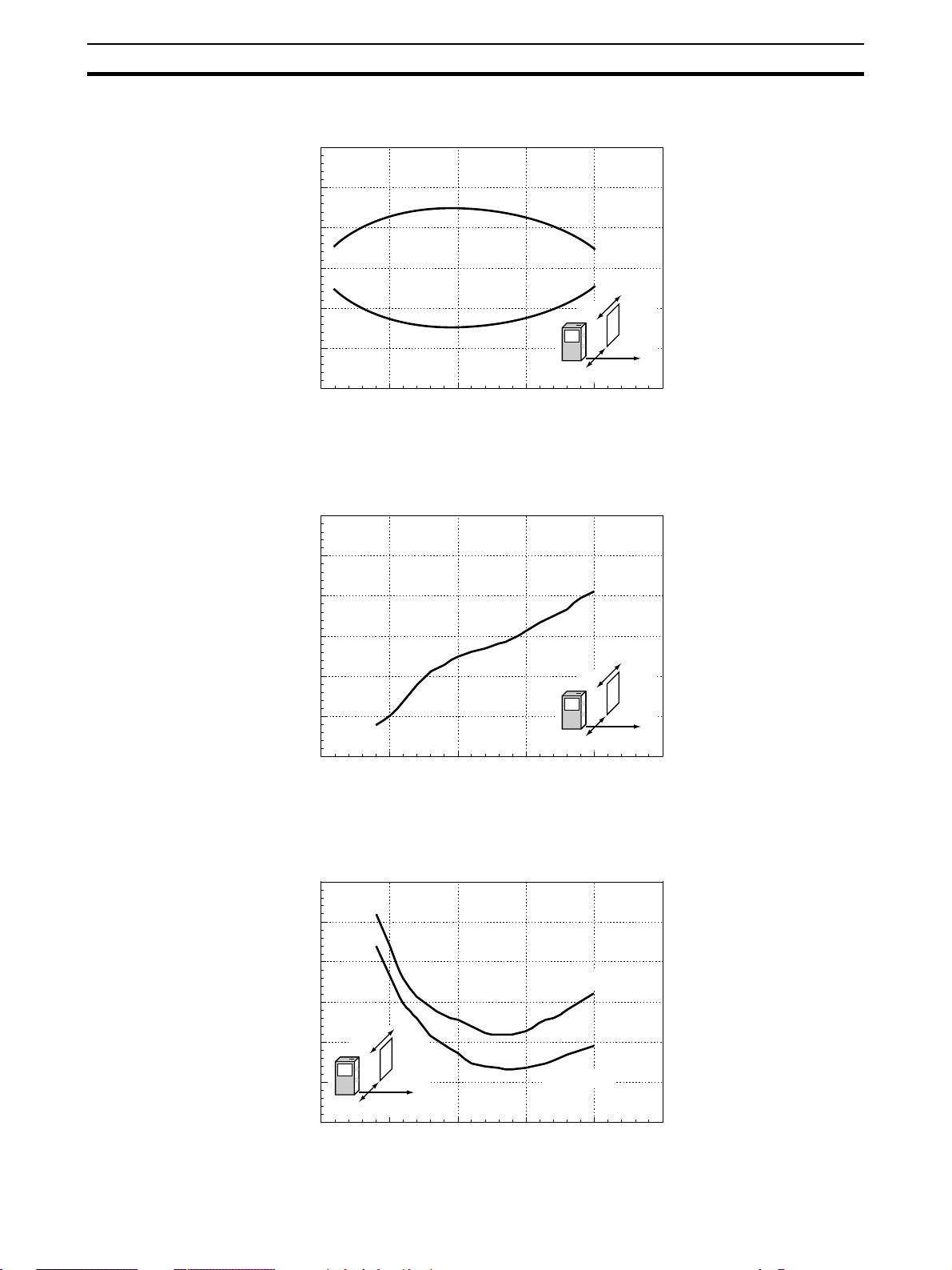
3-1-6 Parallel operating range
30
20
10
0
-10
Object position X (mm)
-20
-30
0 500 1000 1500 2000 2500
E3NT
Object
Z
X
Distance Z (mm)
3-1-7 Black/White-error (6 % / 90 % remission, typical)
20
Section 3-1
15
10
5
0
Black/White-error (%)
-5
-10
0 500 1000 1500 2000 2500
3-1-8 Hysteresis (typical)
15
10
Distance Z (mm)
E3NT
X
black object
Object
Z
16
5
Hysteresis (%)
E3NT
0
0 500 1000 1500 2000 2500
Object
Z
X
white object
Distance Z (mm)
Page 16

Optical data link E3NT-AL232 (order separately)
3-2 Optical data link E3NT-AL232 (order separately)
Dimensions (length x width x depth) 29.5 x 72.9 x 26.4 mm
Housing material ABS and PMMA (IR transparent)
Housing colour Black, RAL 9005
Assembly Snap mounting on sensor
Connection 2 m connecting cable with 9-pole sub-D connector
Ambient temperature range - 10 °C ... + 50 °C
Storage temperature range - 40 °C ... + 60 °C
Permissible relative humidity 35 % ... 85 %, no condensation
Degree of protection to EN 60529 / IEC 529 IP 54
Emitted light IR communication element 880 nm
Rated operating voltage Via RS232 interface from PC
Current consumption 6 mA
Section 3-2
17
Page 17
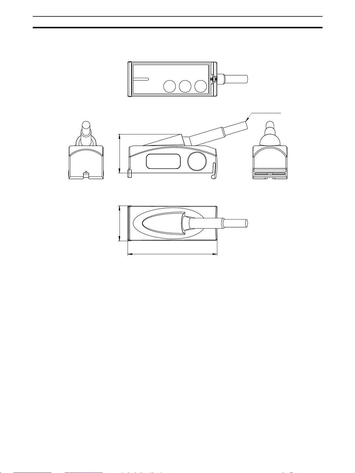
Dimensions
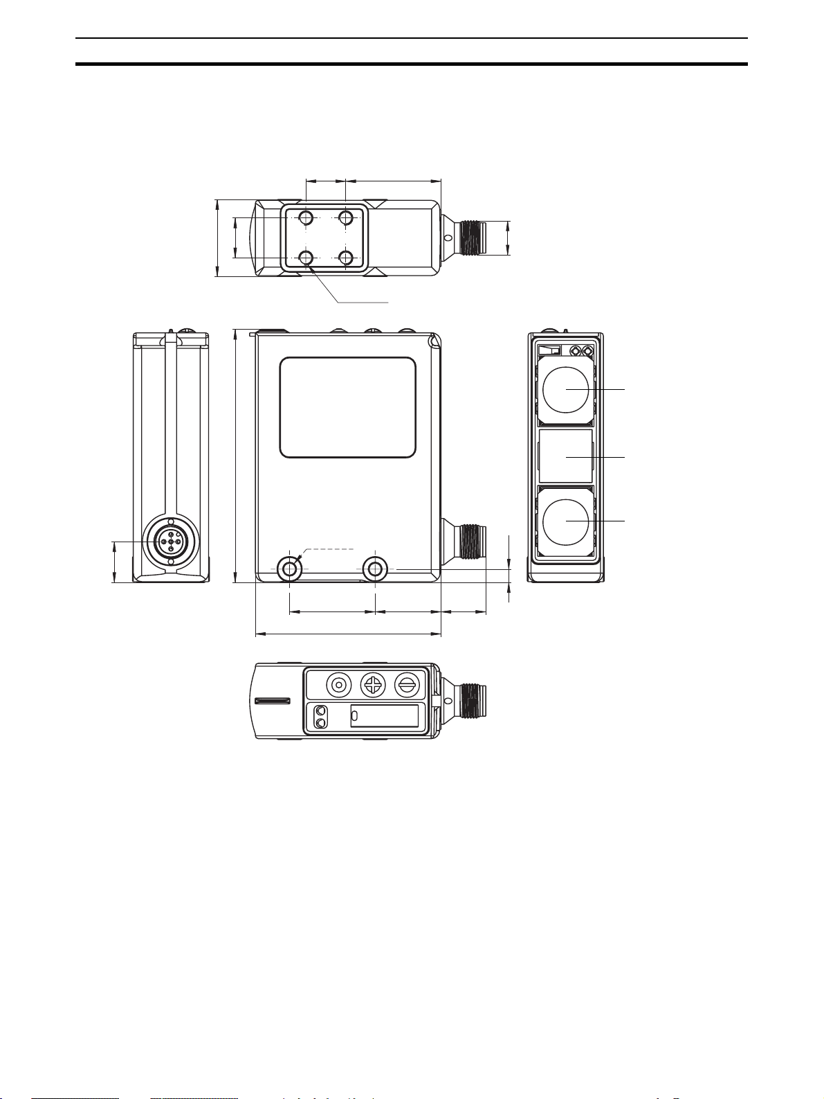
3-3 Dimensions
3-3-1 Sensor E3NT-L17 with horizontal connector
14 33.4
27
14
M5 (4x)
M12
Section 3-3
receiver 1
88.7
M5 (2x)
14.3
30 23.1 15.7
65.1
4.7
emitter
receiver 2
18
Page 18
Dimensions
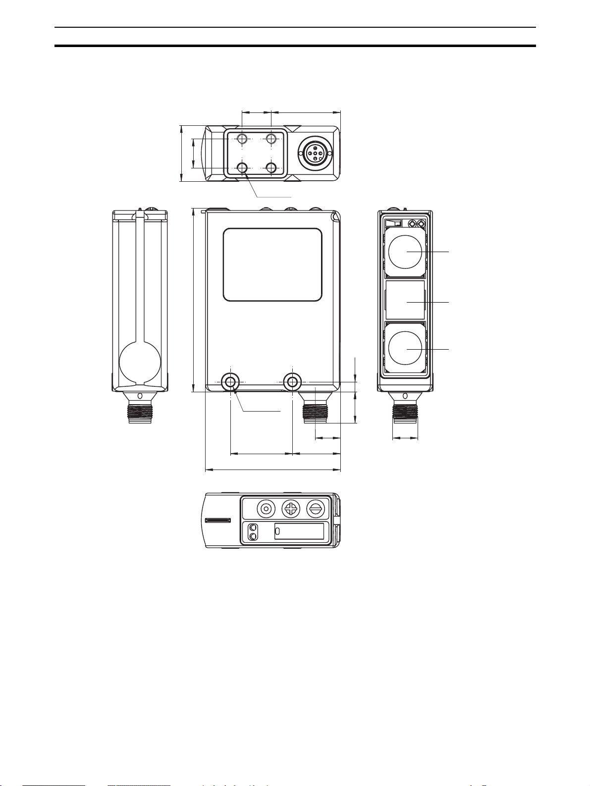
3-3-2 Sensor E3NT-L37 with vertical connector
14 33.4
14
27
M5 (4x)
Section 3-3
receiver 1
88.7
4.7
M5 (2x)
12.1
23.130
65.1
15.2
M12
emitter
receiver 2
19
Page 19
Dimensions
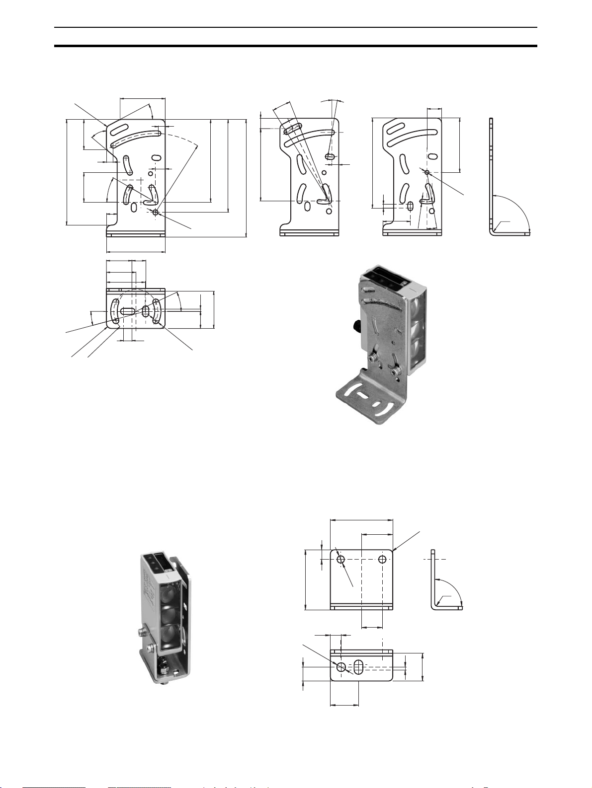
3-3-3 Universal mounting bracket E39-EL1 (order separately)
Section 3-3
26
30
39.5
46
28°
7
84.5
10
80.62
R
60
14
8.5
R
3
0
ø 5.3 ±0.1
25
°
ø 6.3 ±0.1
95
120±1
2.5
38±1
17.5
°
10
10.5
74
R
5
x 7
50°
31
7
108
°
30
30
11
15°
28.4
R
x 2
5
22.5
R
R
°
9.5
25
R
R
8
2
.7
4
7
92
4
28
15
55.5
ø 4.2 ±0.1
90
°
R
30
10°
ø 4.2 ±0.1
Rx
3-3-4 Adapter bracket E39-EL2 (order separately)
45
22.5
7
ø 5.2
43.4
7.8
ø 6.3
10
20.3
20
15
3
R
90°
Rx
2
20
Page 20
Dimensions
3-3-5 Optical data link E3NT-AL232 2m (order separately)
cable 2 m
30
Section 3-3
27
68,9
21
Page 21

Dimensions
Section 3-3
22
Page 22

4-1 Functions. . . . . . . . . . . . . . . . . . . . . . . . . . . . . . . . . . . . . . . . . . . . . . . . . . . . . 24
4-2 Display and operator controls . . . . . . . . . . . . . . . . . . . . . . . . . . . . . . . . . . . . . 26
4-2-1 LED display . . . . . . . . . . . . . . . . . . . . . . . . . . . . . . . . . . . . . . . . . . . 26
4-2-2 LEDs. . . . . . . . . . . . . . . . . . . . . . . . . . . . . . . . . . . . . . . . . . . . . . . . . 26
4-2-3 Push buttons on the sensor . . . . . . . . . . . . . . . . . . . . . . . . . . . . . . . . 27
4-2-4 Set-up via a PC . . . . . . . . . . . . . . . . . . . . . . . . . . . . . . . . . . . . . . . . . 27
4-3 User set parameters . . . . . . . . . . . . . . . . . . . . . . . . . . . . . . . . . . . . . . . . . . . . . 27
4-3-1 Mode. . . . . . . . . . . . . . . . . . . . . . . . . . . . . . . . . . . . . . . . . . . . . . . . . 28
4-3-2 Output function. . . . . . . . . . . . . . . . . . . . . . . . . . . . . . . . . . . . . . . . . 29
4-3-3 Switching points . . . . . . . . . . . . . . . . . . . . . . . . . . . . . . . . . . . . . . . . 29
4-3-4 Output switching. . . . . . . . . . . . . . . . . . . . . . . . . . . . . . . . . . . . . . . . 29
4-3-5 Function of connector pin 2 . . . . . . . . . . . . . . . . . . . . . . . . . . . . . . . 30
4-3-6 Switch-on delay . . . . . . . . . . . . . . . . . . . . . . . . . . . . . . . . . . . . . . . . 30
4-3-7 Switch-off response . . . . . . . . . . . . . . . . . . . . . . . . . . . . . . . . . . . . . 30
4-3-8 Timing diagrams. . . . . . . . . . . . . . . . . . . . . . . . . . . . . . . . . . . . . . . . 31
4-3-9 Type of display . . . . . . . . . . . . . . . . . . . . . . . . . . . . . . . . . . . . . . . . . 32
4-3-10 Keyboard lock. . . . . . . . . . . . . . . . . . . . . . . . . . . . . . . . . . . . . . . . . . 32
4-3-11 ECO energy saving mode . . . . . . . . . . . . . . . . . . . . . . . . . . . . . . . . . 32
4-3-12 Direction of the display . . . . . . . . . . . . . . . . . . . . . . . . . . . . . . . . . . 32
4-3-13 Reset . . . . . . . . . . . . . . . . . . . . . . . . . . . . . . . . . . . . . . . . . . . . . . . . . 32
4-4 Inputs/Outputs. . . . . . . . . . . . . . . . . . . . . . . . . . . . . . . . . . . . . . . . . . . . . . . . . 33
4-4-1 Inputs . . . . . . . . . . . . . . . . . . . . . . . . . . . . . . . . . . . . . . . . . . . . . . . . 33
4-4-2 Outputs . . . . . . . . . . . . . . . . . . . . . . . . . . . . . . . . . . . . . . . . . . . . . . . 34
SECTION 4
Function
23
Page 23

Functions
4-1 Functions
Section 4-1
Diffuse reflective sensors in the E3NT type series can be operated with background and foreground suppression. Genuine window evaluation can also be
set. The distance is evaluated in accordance with the double triangulation
principle. In this case, the distance from the measured object is determined
not only via the intensity of the reflected emitted light, but also via the angle
between the emitter, the measured object and the receiver.
Contrary to sensors with single triangulation, E3NT with double triangulation, allows measured object's direction of motion to be in all three
directions. Thus, the rotatory position of the sensor about its optical
axis can be chosen freely
(see Figure 1 Position of the sensor)
.
Figure 1 Position of the sensor
If the light spot is not completely on the same plane target object (minimum object size) the distance is not determined and malfunction can
occur
(see Figure 2 Not determined distance)
signal or timer function has to be applied.
Figure 2 Not determined distance
Measured objects are detected only within the user set and strictly limited
sensing zone. Objects outside the sensing zone (depending on the settings, in
the background, in the foreground or outside of a window that is defined by
two user set distance points) are ignored.
. If necessary a trigger
24
Page 24

Functions
Section 4-1
Due to the infrared emitted light and the very low minimum reflection factor of
6 %, objects can be detected largely independently of their colour and their
surface finish. The sensor can be user set by push button on the unit or with a
3
PC and the SensorSupportSoftware S
data interface E3NT-AL232 (order separately). The optical data interface
operates with an IR communication element. Through the optical data interface, the analog distance data can also be transferred continously to a PC/
laptop and stored there.
(order separately) via an optical
25
Page 25

Display and operator controls
4-2 Display and operator controls
Operating states are displayed by a 4-digit 7-segment LED display and two
LEDs.
The sensor can be operated/set either by push buttons on the sensor or with a
PC and setting software (order separately) via an optical data interface (order
separately).
Section 4-2
Decrement Increment ENTER
4-2-1 LED display
Status LEDLED display
Figure 3 Operator controls and displays
The distance from the measured object and the names of the menu levels
during set-up of the sensor are displayed by the 4-digit 7-segment LED display. The display appears as red digits or letters.
If the sensor is set to a bar chart display, the distance from the measured
object is displayed as a green LED bar chart.
optical IR element for data communication
Red LED
(Output 2)
Yellow LED
(Output 1)
Alignment aid
4-2-2 LEDs
The switching status and the stability of the two outputs are signalled as follows by two LEDs, visible from the top and the front of the sensor:
• Yellow LED ON: Object stably detected
(Output 1) Blinking: Object not stably detected
OFF: No object within range
• Red LED ON: Object stably detected
(Output 2) Blinking: Object not stably detected
OFF: No object within range
The status LED is only visible from the top of the sensor:
• Status LED ON: Set-up menu selected
Blinking: Menu level with change of setting distance
OFF: RUN (normal) mode
26
Page 26

User set parameters
4-2-3 Push buttons on the sensor
On the sensor, there are three push buttons for the setting of the sensor
Figure 3 Operator controls and displays)
• Minus key 팫
• Plus key 팬
• Enter key ●
With these three push buttons, the operator moves through the sensor's menu
and sets the parameters in accordance with the application. Therefore, the
most frequently used parameters can be set directly on the sensor.
4-2-4 Set-up via a PC
All parameters of the sensor can be set with a PC and the OMRON SensorSupportSoftware S
established via an optical data interface. The data interface is connected to a
free COM port of a PC/laptop.
Refer to the separate operating instructions ABBO 0018 for further information on setting with a PC and the SensorSupportSoftware S
Section 4-3
(see
:
3
. The connection between the sensor and the PC is
3
.
4-3 User set parameters
The following parameters can be user set either by push buttons on the sensor or with a PC and the set-up software (order separately) via the optical data
interface (order separately):
• Mode
• Output function
• Teach/set switching points
• Output switching
• Function on connector pins 2 and 5
• Switch-on and off delay
• Type of switch-off time function
• Type of display on the sensor
• Keyboard lock
• Energy saving mode
• Display direction
• Reset to factory defaults
The following functions can only be set with a PC and the set-up software
(order separately) via the optical data interface (order separately):
• Complete sensor locking
27
Page 27

User set parameters
O
1
O
1
4-3-1 Mode
Section 4-3
The diffuse reflective sensor can be operated in the following modes:
• Background suppression BGS (factory default)
Measured objects are detected as from the blind zone up to the user set
or teached switching point S
set switching point, are ignored.
utput
. Objects in the background, behind the user
A
1
A
0
S
S
A
Figure 4 Background suppression
Accordingly for output 2 the switching point C (SC) is set.
• Foreground suppression FGS
Measured objects are detected as from the user set switching point S
to the maximum sensing distance. Objects in the foreground, between the
sensor’s blind zone and the user set switching point, are ignored.
utput
A
up
28
1
A
0
S
S
A
Figure 5 Foreground suppression
Accordingly for output 2 the switching point C (SC) is set.
Page 28

User set parameters
O
1
Section 4-3
• Window evaluation
Measured objects are detected only in the measurement window between
the two user set switching points (switching zone). Objects outside of this
measurement window in the foreground and in the background are
ignored.
Window evaluation involves logical AND combination of the FGS and
BGS modes.
utput
1
0
4-3-2 Output function
The output function can be set separately for both outputs:
A
S
A
Figure 6 Window evaluation
Accordingly for output 2 the switching points C and D are set.
• Light on (factory default)
The output is active when a measured object is detected.
• Dark on
The output is active when no measured object is detected.
S
B
B
S
4-3-3 Switching points
The switching points can be set on a positioned measured object or can be
user set by input of switching points.
In the window evaluation mode, two switching points must be defined for
each output.
In the FGS or BGS mode, only one switching point needs to be defined for
each output.
4-3-4 Output switching
Output switching can be user set jointly for both outputs:
• PNP, plus-switching, open collector (factory default)
• NPN, minus-switching, open collector
• Push-pull, complementary, plus/minus-switching
See SECTION 7-3 Connection diagrams.
29
Page 29

User set parameters
4-3-5 Function of connector pin 2
Pin 2 of the connector can be user set as Output 2 (OUT 2), as an alarm output, as a teaching input for switching points A and B, as a test input or as a
trigger input.
4-3-6 Switch-on delay
This defines the switch-on response (light-on mode). The time is adjustable
between 0 ms and 9999 ms.
• Switch-on delay
The switch-on delay starts as from the time when the measured object
enters the sensing zone. The output does not become active until the
switch-on delay has elapsed.
4-3-7 Switch-off response
This defines the switch-off response (light-on mode). The time is adjustable
between 0 ms and 9999 ms.
• Switch-off delay
The switch-off delay starts as from the time when the measured object
leaves the sensing zone. The output does not become inactive until the
switch-off delay has elapsed.
Section 4-3
• Minimum pulse width
After detection of a measured object, the output remains active for at least
the user set switch-off delay. If the measured object dwells in the sensing
zone for longer than the set switch-off delay, the output becomes inactive
immediately after the object leaves the sensing zone.
• Constant pulse width
After detection of a measured object, the output only remains active during the user set switch-off delay and becomes inactive after this time has
elapsed, regardless of the measured object's dwell time, even if the
measured object stays in the sensing zone for longer than the user set
switch-off delay.
30
Page 30

Timer functions off
object
detected
not detected
ON
OFF
Mode on-1 (on-/off-delay)
object
only on-delay
only off-delay
detected
not detected
ON
OFF
ON
OFF
on - and off-delay
Mode on-2 (minimum pulse width)
object
detected
not detected
Td1
Td1
Td2
Td1
Td1
Td2
Td2
Td1
Td1 Td1
Td1
Td2
Td2
Td2
Td2
Td1
Td2
Td1
Td2
Td2
Td1
Td1
Td1
Td2
Td2
Td1
Td1
4-3-8 Timing diagrams
User set parameters
31
ON
OFF
Mode on-3 (constant pulse width)
ON
OFF
note:
Td3
Td3 Td3 Td3 Td3 Td3 Td3 Td3
on-delay: Td1 off-delay: Td2
Td3 Td3 Td3 Td3
min/const.: Td3
Td3
Td3
Section 4-3
Page 31

User set parameters
4-3-9 Type of display
4-3-10 Keyboard lock
Section 4-3
The measured distance can be displayed on the sensor's display in two different ways:
• Absolute
The absolute distance between the sensor and the measured object is
displayed with red digits in m.
• Bar
The distance between the sensor and the measured object is displayed
as a green bar chart.
With the keyboard lock function, the push buttons on the sensor can be locked
to prevent inadvertent modification of the settings.
The lock can be activated and deactivated on the sensor.
When the keyboard lock is active, changes can only be made if the Minus 팫
and Plus 팬 keys have been pressed simultaneously for 4 seconds. This temporarily suppresses keyboard locking. If no key is pressed for about 5 minutes, the keyboard lock is automatically activated again.
4-3-11 ECO energy saving mode
In the ECO mode, the display switches off automatically approximately 5 minutes after the push buttons have been pressed for the last time.
The display is activated again the next time the push buttons are pressed.
Deactivation of the sensor display reduces the sensor's current consumption
by approximately 20 mA.
4-3-12 Direction of the display
To improve readability, the display can be rotated by 180° when fitted. It is
then "upside down".
4-3-13 Reset
Reset returns the sensor to the factory default settings.
32
Page 32

Inputs/Outputs
4-4 Inputs/Outputs
In total, the sensor can be operated with a maximum of three inputs/outputs.
The functions of the inputs/outputs are user determined.
Connector pin 4 is always defined as Output 1 (OUT 1).
Connector pin 2 can be set as Output 2 (OUT 2), as alarm output (ALARM),
as teaching input (TEACH) for switching points A or B, as test input (TEST) or
as trigger input (TRIG).
Connector pin 5 can be set as trigger input (TRIG) as teaching input (TEACH)
for switching points A to D or as test input (TEST)
4-4-1 Inputs
4-4-1-1 Teaching input TEACH
Connector pins 2 and 5 can be set as teaching inputs for the switching points
A to D.
If a signal in the operating voltage range is applied to this input, the sensor is
taught the switching point A, B, C or D depending on the user set preferences.
Section 4-4
4-4-1-2 Test input TEST
Connector pins 2 and 5 can be set as test inputs.
The emitter is deactivated if a signal in the operating voltage range is applied
to this input.
If a measured object is located in the sensor's detection zone, regardless of
the user set switching points the receiver detects the absence of the emitted
light reflected by the measured object.
Depending on the object position the output status is altered.
4-4-1-3 Trigger input TRIG
Connector pin 2 and pin 5 can be set as a trigger input.
If a signal in the operating voltage range is applied to this input, the sensor is
prompted to output a measurement result (object distance).
The sensor/switching speed can be increased by the trigger function.
33
Page 33

Inputs/Outputs
4-4-2 Outputs
4-4-2-1 Switching outputs OUT 1 and OUT 2
When a measured object is detected, the switching outputs OUT 1 (Connector pin 4, fixed) and OUT 2 (Connector pin 2) switch in accordance with the
sensor's settings.
4-4-2-2 Alarm output ALARM
Connector pin 2 can be set as the alarm output.
The alarm output is switched on if the intensity of reflected light is too low or
no measured object is detected.
Section 4-4
34
Page 34

5-1 Packaging / Transportation damage . . . . . . . . . . . . . . . . . . . . . . . . . . . . . . . . 36
5-2 Storage . . . . . . . . . . . . . . . . . . . . . . . . . . . . . . . . . . . . . . . . . . . . . . . . . . . . . . 36
5-3 Scope of delivery. . . . . . . . . . . . . . . . . . . . . . . . . . . . . . . . . . . . . . . . . . . . . . . 36
SECTION 5
Transport
35
Page 35

Packaging / Transportation damage
5-1 Packaging / Transportation damage
• Do not damage the sensor by other objects during transportation
• Only ever use the sensor's original packaging sealed properly for trans-
portation
• Keep the sensor's original packaging for later use
• Report transportation damage immediately in writing to the haulage con-
tractor and OMRON
5-2 Storage
• Only ever store the sensor in original packaging that has been sealed
properly
• Protect against dust and moisture
Section 5-1
5-3 Scope of delivery
The sensor's scope of delivery consists of:
• Diffuse reflective Sensor E3NT-L
• Short-form instructions
• Operating instructions on CD-ROM
36
Page 36

6-1 Safety notes. . . . . . . . . . . . . . . . . . . . . . . . . . . . . . . . . . . . . . . . . . . . . . . . . . . 38
6-2 Sensor assembly . . . . . . . . . . . . . . . . . . . . . . . . . . . . . . . . . . . . . . . . . . . . . . . 38
6-2-1 Sensor's assembly direction . . . . . . . . . . . . . . . . . . . . . . . . . . . . . . . 39
6-2-2 Assembly via assembly holes. . . . . . . . . . . . . . . . . . . . . . . . . . . . . . 40
6-2-3 Assembly by universal mounting bracket E39-EL1. . . . . . . . . . . . . 40
6-2-4 Assembly with adapter bracket E39-EL2 and bracket E39-EL1 . . . 40
SECTION 6
Assembly
37
Page 37

Safety notes
6-1 Safety notes
6-2 Sensor assembly
Section 6-1
Assembly, electrical connection and maintenance must only be carried
out by instructed, trained and authorised specialist personnel in
accordance with applicable regulations, after de-energising the power
supply and with the machine switched off.
The machine must be safeguarded against reactivation.
Conversions and changes and tampering in the interior of the sensor,
the data interface and the alignment tool are forbidden.
During assembly, do not knock the sensor or drop it.
The ambient conditions at the assembly location must conform to the
technical data
Contrary to sensors with single triangulation, E3NT with double triangulation, allows the measured object's direction of motion to be in all
three directions. Thus, the rotatory position of the sensor about its optical axis can be chosen freely
(see SECTION 3 Specification)
(see Figure 1 Position of the sensor)
.
.
38
Figure 1 Position of the sensor
If the light spot is not completely on the same plane as the target
object (minimum object size) the distance is not determined and malfunction can occur
sary a trigger signal or timer function has to be applied.
Figure 2 Not determined distance
(see Figure 2 Not determined distance)
. If neces-
Page 38

Sensor assembly
The sensor must be fitted so that:
• It is correctly aligned before it is adjusted
• It is protected as far as possible against vibration and shock
• It is protected as far as possible against extraneous incident light
• It is protected as far as possible against damage and soiling
• Electrical connection is possible
• It is as accessible as far as possible for maintenance work
• Operation of the push buttons is possible
• The display is visible.
6-2-1 Sensor's assembly direction
As far as possible, the sensor's optical surface should be aligned parallel to
the surface of the measured object.
Section 6-2
90°
detection object
90°
Figure 3 Parallel alignment
If the measured object has a glossy, reflecting surface, the sensor's
optical system should be tilted by 5 … 10° in relation to the surface of
the measured object.
5 … 10°°
90°
detection object
Figure 4 Alignment for glossy surfaces
39
Page 39

Sensor assembly
If there is a reflecting surface in parallel with the sensor's optical axis,
this might lead to unstable switching states.
Therefore, reflecting objects within the sensor's optical axis should be
avoided.
If this should not be possible, the reflecting surface should not be parallel to the sensor's optical axis, but should be rotated by at least 10°.
Mirror-like objects can cause malfunction inside and outside the sensing range. Avoid mirror-like objects in or close to the optical axis.
6-2-2 Assembly via assembly holes
1. Professionally produce securing holes/threaded holes corresponding to
the six possible assembly holes of the sensor
sions)
.
2. Professionally attach the sensor with suitable securing material.
3. Roughly align the sensor to the possible position of the measured object.
4. Tighten the securing screws.
Section 6-2
(see Section 3-3 Dimen-
6-2-3 Assembly by universal mounting bracket
E39-EL1
1. Drill and tap the necessary securing holes / threaded holes according to
the required pattern of the universal mounting bracket
mensions)
2. Using the included securing material, professionally fit the sensor on the
mounting bracket.
3. With suitable securing material, professionally fit the mounting bracket on
the body of the machine.
4. Roughly align the sensor to the possible position of the measured object.
5. Tighten the securing screws.
.
(see Section 3-3 Di-
6-2-4 Assembly with adapter bracket E39-EL2 and
bracket E39-EL1
Applying the adapter bracket E39-EL2 the universal mounting bracket E39EL1 can be used as an adapter plate to mount the E3NT to existing holes.
1. Mount the bracket E39-EL1 to the existing assembly holes on the machine,
if necessary produce additional ones.
2. Using the included securing material of the E39-EL1 professionally fit the
sensor to the adapter bracket E39-EL2.
3. Using the included securing material professionally fit the adapter bracket
to the universal mounting bracket E39-EL1.
40
Page 40

Electrical Connection
7-1 Safety notes. . . . . . . . . . . . . . . . . . . . . . . . . . . . . . . . . . . . . . . . . . . . . . . . . . . 42
7-2 Establishing electrical connection. . . . . . . . . . . . . . . . . . . . . . . . . . . . . . . . . . 42
7-3 Connection diagrams. . . . . . . . . . . . . . . . . . . . . . . . . . . . . . . . . . . . . . . . . . . . 43
7-3-1 Output circuits . . . . . . . . . . . . . . . . . . . . . . . . . . . . . . . . . . . . . . . . . 43
7-3-2 Input circuits. . . . . . . . . . . . . . . . . . . . . . . . . . . . . . . . . . . . . . . . . . . 44
7-3-3 Connector pin assignments. . . . . . . . . . . . . . . . . . . . . . . . . . . . . . . . 45
7-4 Connection in line with EMC requirements . . . . . . . . . . . . . . . . . . . . . . . . . . 45
SECTION 7
41
Page 41

Safety notes
7-1 Safety notes
Section 7-1
Assembly, electrical connection and maintenance must only be carried
out by instructed, trained and authorised specialist personnel in
accordance with applicable regulations, after de-energising the power
supply and with the machine switched off.
The machine must be safeguarded against reactivation.
Conversions and changes and tampering in the interior of the sensor,
the data interface and the alignment tool are forbidden.
A technical data of the supply voltage and of the input/output wires
must conform to the technical data of the sensor (see sensor rating
plate and SECTION 3 Specification).
Do not lay the sensor's connecting leads in the direct proximity of
cables carrying higher voltages or together with cables that switch
inductive or capacitive loads.
A power supply unit that conforms to the necessary EMC requirements
must be used.
The operating voltage must be within the applicable operating voltage
range. Unstabilised full or half-wave rectifiers must not be used for the
power supply.
The electrical connection must conform to EMC requirements.
The equipotential bonding system for the machine must be produced
in conformity with EN 60204-1, Section 8 "Equipotential bonding".
Check the operability of all equipotential bonding conductors in conformity with Section 20 of EN 60204-1 before releasing the machine
for operation.
7-2 Establishing electrical connection
1. Establish electrical connection in conformity with the pin assignments described in SECTION 7-3 Connection diagrams.
2. Professionally establish the equipotential bonding system, the protective
earthing, the shielding and the sensor wiring in line with EMC requirements
(see Section 7-4 Connection in line with EMC requirements)
.
42
Page 42

Connection diagrams
7-3 Connection diagrams
7-3-1 Output circuits
Internal circuit
Figure 1 Push-pull output circuit (OUT1 at pin 4 / OUT2 at pin 2)
T
PNP
T
NPN
E3NT
1
4
3
+ U
S
OUT1
0 V
Section 7-3
+ U
B
OUT1
OUT2
0 V
The sensor is factory set to a PNP output.
The output circuit is resistant to short-circuits and reversed power supply.
When use is made of the PNP or NPN output circuit, the output circuit that is
not selected is deactivated.
When used as a complementary output, NPN or PNP outputs act in antiphase
as the switch state changes.
PNP
1
4
2
L
1
L
3
2
Figure 2 PNP/NPN load connection
+ U
B
OUT1
OUT2
0 V
NPN
1
4
2
3
L
1
L
2
43
Page 43

Connection diagrams
7-3-2 Input circuits
+ U
In1 5
0 V 3
Section 7-3
The sensor inputs are realised in positive logic and detect a positive voltage
level of more than 1 ms duration as a valid signal if the voltage level is
between 10 V and the power supply voltage.
E3NT
1
S
Figure 3 Input circuit input 1 (IN1 at pin 5)
Internal circuit
+ U
S
In2 2
0 V 3
E3NT
1
Internal circuit
Figure 4 Input circuit input 2 (IN2 at pin 2)
Pin 2 can be set as input or output (factory default)
44
Page 44

Connection in line with EMC requirements
7-3-3 Connector pin assignments
The sensor is connected by means of a standard 5-pole M12 connector
Figure 5 Connector pin assignments)
(View of connector pins on the sensor)
Figure 5 Connector pin assignments
.
+ U
S
OUT2 / IN2
0 V
OUT1
IN1
7-4 Connection in line with EMC requirements
Section 7-4
(see
• In environments with interference levels, use cables with twisted-pair
wires and/or shielded cables.
• When cables are introduced into an EMC control cabinet, guide the cable
shield without interruption through the wall of the EMC control cabinet
(e.g. via a cable conduit).
• Professionally connect the cable shield to the control cabinet housing (flat
surface, conductive).
• Professionally connect wires of cables or free cable ends that are not
used to the cable shield on both ends of the cable.
• If the control cabinet is connected by means of connectors, use connectors with a metal housing and a leading protective earth contact (in
accordance with EN 60204-1) only.
• Conductively connect the cable shield to the connector housing.
• Professionally connect the mating connector to the control cabinet hous-
ing (flat surface, conductive).
• Route supply and signal leads in separate cable ducts.
• Route supply and signal leads as closely as possible to the equipotential
bonding conductor.
• Do not route cable ducts in the proximity of strong electromagnetic interference sources such as electric motors or transformers.
• Suitable protective measures conforming to EN 60204-1 must be taken if
the cable layout does not fully rule out the risk of lightning strikes.
45
Page 45

Connection in line with EMC requirements
Section 7-4
46
Page 46

Setting into Operation
8-1 Safety notes. . . . . . . . . . . . . . . . . . . . . . . . . . . . . . . . . . . . . . . . . . . . . . . . . . . 48
8-2 Switching on the operating voltage. . . . . . . . . . . . . . . . . . . . . . . . . . . . . . . . . 48
8-3 Aligning the sensor . . . . . . . . . . . . . . . . . . . . . . . . . . . . . . . . . . . . . . . . . . . . . 49
8-4 Setting the switching points . . . . . . . . . . . . . . . . . . . . . . . . . . . . . . . . . . . . . . 50
8-4-1 Teaching the switching points in the normal mode . . . . . . . . . . . . . 50
8-4-2 Setting the sensor . . . . . . . . . . . . . . . . . . . . . . . . . . . . . . . . . . . . . . . 50
SECTION 8
47
Page 47

Safety notes
8-1 Safety notes
The diffuse reflective sensors in the E3NT type series may only be
used as described in these operating instructions.
They may only be operated as part of a higher-level overall system,
e.g. of a machine installation.
Diffuse reflective sensors in the E3NT type series must not be used as
safety components within the scope of the EU machine guideline.
Their use is not permitted in applications in which the safety of persons
depends on functioning of the sensor!
8-2 Switching on the operating voltage
After the operating voltage has been switched on, the sensor runs a power-on
reset with a self-test.
The sensor displays the current distance from the measured object if the selftest is successful.
0--0 is displayed if the sensor does not detect a measured object.
Section 8-1
The flashing display ---- appears in the event of a short-circuit at the
outputs.
The sensor continues normal functioning once the short-circuit at the
outputs has been remedied.
48
Page 48

Aligning the sensor
8-3 Aligning the sensor
Owing to the infrared emitted light, the light spot on the measured
object is not visible.
Hence the sensor must be aligned relative to the optical axis.
The alignment marking on the top of the sensor can be used as a
sighting line for the optical axis, thus simplifying alignment
1 Aligning the sensor)
1. Position the measured object at the required position in front of the sensor.
2. Undo the securing screws.
3. Align the sensor's optical axis/alignment marking to the measured object.
4. Tighten the securing screws.
5. Check alignment once again.
Section 8-3
(see Figure
.
Alignment marking
Figure 1 Aligning the sensor
90°
detection object
90°
49
Page 49

Setting the switching points
8-4 Setting the switching points
The switching points can either be user set (Teach-in mode) with a measured
object positioned at the corresponding distance or can be set using the setting
input, for remote setting.
For each output of the sensor (up to two), up to two switching points can be
user set.
Only one switching point is active in the foreground and background suppression modes.
For the 2-point window evaluation mode, two switching points must be set.
8-4-1 Teaching the switching points in the normal mode
The sensor is set at the factory for both outputs to BGS, light on.
1. Place the target object in front of the sensor at the desired position.
2. Teach the switching point for output 1:
• Beginning with the 팬 key, press it simultaneously with the ENTER ●
key. Threshold level is obtained and the output/LED is updated. Status
LED is blinking.
• Using the 팬/팫 keys an adjustment of the switching point is possible.
The output/LED is updated immediately.
• Pressing the ENTER ● key for more than 2 seconds or after 2 minutes
without any activation of the keys, the sensor returns to normal operation. The status LED is turned off.
3. Teach the switching point for Output 2:
• Beginning with the 팫 key, press it simultaneously with the ENTER ●
key.
Section 8-4
8-4-2 Setting the sensor
The sensor's parameters and the four possible switching points are set as
described in Section
9-2 Setting the sensor with a PC
9-1 Setting the sensor using the push buttons
.
or Section
50
Page 50

Sensor Set-up
9-1 Setting the sensor using the push buttons . . . . . . . . . . . . . . . . . . . . . . . . . . . . 52
9-1-1 Display in the normal mode . . . . . . . . . . . . . . . . . . . . . . . . . . . . . . . 52
9-1-2 Main menu structure. . . . . . . . . . . . . . . . . . . . . . . . . . . . . . . . . . . . . 53
9-1-3 TEACH menu path . . . . . . . . . . . . . . . . . . . . . . . . . . . . . . . . . . . . . . 54
9-1-4 SET menu path . . . . . . . . . . . . . . . . . . . . . . . . . . . . . . . . . . . . . . . . . 56
9-1-5 OPTIONS menu path . . . . . . . . . . . . . . . . . . . . . . . . . . . . . . . . . . . . 58
9-2 Setting the sensor with a PC . . . . . . . . . . . . . . . . . . . . . . . . . . . . . . . . . . . . . . 60
SECTION 9
51
Page 51

Setting the sensor using the push buttons
9-1 Setting the sensor using the push buttons
The sensor is set by means of three push buttons.
With these push buttons, the user navigates through the setting menus,
through which all necessary sensor settings can be made.
If no keys are pressed for 2 minutes during set-up, the sensor returns
automatically to run mode.
9-1-1 Display in the normal mode
Depending on the user set-up, the sensor's display shows the following in the
run mode:
• Status LED is turned off.
• Digital display:
The current distance from the sensor to the measured object in m.
• Bar display:
The current distance from the sensor to the measured object as a bar.
Section 9-1
The display shows 0--0 if the sensor does not detect a measured
object.
The flashing display ---- appears in the event of a short-circuit on the
outputs.
The sensor resumes normal functioning when a short-circuit on the
outputs is eliminated.
The On-delay-setting tr-1 or tr-2 are only available if the switch-on/off delay
in the OPTIONS menu path is set to on-1.
52
Page 52

Setting the sensor using the push buttons
9-1-2 Main menu structure
The following figure shows the structure of the main set-up menu.
Normal
operation
Enter 2 s
Section 9-1
OFFON
tch
팫 / 팬 팫 / 팬
Menu path
TEACH
Switching
point
settings
Enter 2 s
Menu path
Figure 1 Structure of the main set-up menu
When the Enter ● key is pressed for 2 seconds, the sensor switches from the
normal mode to the TEACH menu path. The sensor switches to each next
menu path when the Enter ● key is repeatedly pressed for 2 seconds.
In the menu paths, the required parameters can be selected by pressing the
팫 and 팬 keys.
To skip a menu path, you can also press the Enter ● key for 4 seconds.
Enter Press the Enter ● key < 1 second.
5Et
SET
Function
settings
Enter 2 s Enter 2 s
0Pt
팫 / 팬
Menu path
OPTIONS
Additional
settings
Status LED
Enter 2 s Press the Enter ● key > 2 seconds.
53
Page 53

Setting the sensor using the push buttons
9-1-3 TEACH menu path
The switching points of the outputs are tought or set-up in the TEACH menu path.
The Status LED is on, blinking, during setpoint settings.
Section 9-1
Menu items
Teaching
Switching point A
Output 1
Teaching
Switching point B
Output 1
Teaching
Switching point C
Output 2
Teaching
Switching point D
Output 2
2.)
2.)
Normal
operation
Enter 2 s
tch
tc-A
1.)
tc-b
tc-C
1.)
tc-d
Enter 2 s
Enter
Enter
Enter
Enter
Switch. point A
Switch. point B
Switch. point C
Switch. point D
Status LED is blinking
Output 1
teached
Output 1
teached
Output 2
teached
Output 2
teached
Status LED
Status LED
is blinking
is blinking
Set
Switch. point A
in m
with 팫 / 팬
Set
Switch. point B
in m
with 팫 / 팬
Set
Switch. point C
in m
with 팫 / 팬
Set
Switch. point D
in m
with 팫 / 팬
Enter
Enter
Enter
Enter
Setting of
Switching point A
Output 1
0 ... 2.5 m
in 1 cm increments
Setting of
Switching point B
Output 1
0 ... 2.5 m
in 1 cm increments
Setting of
Switching point C
Output 2
0 ... 2.5 m
in 1 cm increments
Setting of
Switching point D
Output 2
0 ... 2.5 m
in 1 cm increments
2.)
2.)
Set
Ad-A
1.)
Ad-b
Ad-C
1.)
Ad-d
Enter 2 s
Enter Enter
Enter Enter
Enter Enter
Enter Enter
Switch. point A
in m
with 팫 / 팬
Set
Switch. point B
in m
with 팫 / 팬
Set
Switch. point C
in m
with 팫 / 팬
Set
Switch. point D
in m
with 팫 / 팬
Output 1
Switch. point A
set
Output 1
Switch. point B
set
Output 2
Switch. point C
set
Output 2
Switch. point D
set
5Et
Figure 2 TEACH menu path
54
Page 54

Setting the sensor using the push buttons
Remarks
1. In the 2-point window evaluation mode, two switching points (A/B and C/D)
can be set for each output.
In the foreground and background suppression modes, only one switching
point (A and C) can be set for each output. Then, only these switching
points, A and C, can be set in the TEACH menu path. B and D switching
points are not available.
2. If connector pin 2 is set as an input, only the switching points for Output 1
can be set.
Section 9-1
55
Page 55

Setting the sensor using the push buttons
9-1-4 SET menu path
All function parameters of the sensor are defined in the SET menu path.
The Status LED is on.
Section 9-1
Menu items
Function
Output 1
Function
Output 2
Switch-on
delay
Output 1
0 ... 9999 ms
in 1 ms decrements
1.)
2.) 5.)
Normal
operation
Enter 2 s
Enter 2 s
5Et
0ut1
0ut2
tr-1
Enter 2 s
Background
Set time
in ms
with팫 / 팬
suppression
Foreground
suppression
Window
evaluation
Background
suppression
Foreground
suppression
Window
evaluation
Select
Enter
function
with
팫 / 팬
Select
Enter
function
with
팫 / 팬
Enter Enter
b65
Enter
F65
2-P
b65
Enter
F65
2-P
Switch-on
delay
Output 1
parameterised
Select
function
with
팫 / 팬
Select
function
with
팫 / 팬
light-on
dark-on
light-on
dark-on
L-on
d-on
L-on
d-on
Enter
Enter
Switch-off
2.) 3.)
delay
Output 1
0 ... 9999 ms
in 1 ms decrements
Switch-on
2.) 5.)
delay
Output 2
0 ... 9999 ms
in 1 ms decrements
Switch-off
delay
Output 2
0 ... 9999 ms
in 1 ms decrements
Distance
display
Key
lock
1.)
2.) 3.)
1.)
4.)
Enter 2 s
tF-1
tr-2
tF-2
di5P
L0CH
Enter Enter
Enter Enter
Enter
Enter Enter
Set time
in ms
with팫 / 팬
Set time
in ms
with팫 / 팬
Set time
in ms
with팫 / 팬
Select
function
with
팫 / 팬
Select
function
with
팫 / 팬
Enter
Absolute
Bar
graph
Locking
OFF
Locking
ON
Switch-off
delay
Output 1
parameterised
Switch-on
delay
Output 2
parameterised
Switch-off
delay
Output 2
parameterised
Ab5
bAr
oFF
EnterEnter
on
56
0Pt
Figure 3 SET menu path
Page 56

Setting the sensor using the push buttons
Remarks
1. If connector pin 2 is set as an input, the switch-on/off delay function can
only be set for Output 1. A second switching output is not available.
2. If the switch-on/off delay is off in the OPTIONS menu path, the switch-on/
off delay parameters do not appear in the SET menu path.
3. The outputs behave differently depending on the switch-off delay function
that is set in the OPTIONS menu path.
4. The key lock becomes active again when no keys have been pressed for
approx. 5 minutes.
The key lock can be temporarily cancelled by pressing the 팫 and 팬 keys
for 4 seconds.
5. The On-delay-setting tr-1 or tr-2 are only available if the switch-on/off delay in the OPTIONS menu path is set to on-1.
Section 9-1
57
Page 57

Setting the sensor using the push buttons
9-1-5 OPTIONS menu path
All function options of the sensor are defined in the OPTIONS menu path.
The Status LED is on.
Section 9-1
Menu items
Function
Connector pin 2
Function
Connector pin 5
Function
Switch-on /
switch-off
delay
Output 1
Function
Switch-on /
switch-off
delay
1.)
Output 2
Normal
operation
Enter 2 s
Enter 2 s
Enter 2 s
0Pt
Pin2
Pin5
ti-1
ti-2
Enter 2 s
Enter
Enter
Enter
Enter
Select
function
with
팫 / 팬
Select
function
with
팫 / 팬
Select
function
with
팫 / 팬
Select
function
with
팫 / 팬
Input
Output
Teach input A
Teach input B
Teach input C
Teach input D
Test input
Trigger input
Switch-on / switch-off
delay OFF
Switch-on / switch-off
delay NORMAL
Switch-off delay
Minimum pulse width
Switch-off delay
Single pulse
Switch-on / switch-off
delay OFF
Switch-on / switch-off
delay NORMAL
Switch-off delay
Minimum pulse width
Switch-off delay
Single pulse
in
out
Enter
Enter
tchA
tchb
tchC
tchd
tE5t
tri6
Enter
oFF
on-1
on-2
on-3
oFF
on-1
on-2
on-3
Enter
Enter
Select
function
with
팫 / 팬
Select
function
with
팫 / 팬
Teach input A
Teach input B
Test input
Trigger input
Switching
output
Alarm output
tchA
tchb
tE5t
tri6
out2
ALAr
Enter
Enter
Energy saving mode
2.)
ECO
Turn display
Output
stage
Reset
to
Works default
58
Enter 2 s
Normal
operation
EC0
FLiP
n-P
r5Et
Enter
Enter
Enter
Enter
Select
function
with
팫 / 팬
Select
function
with
팫 / 팬
Select
function
with
팫 / 팬
Select
function
with
팫 / 팬
ECO-Mode
ON
ECO-Mode
OFF
oFF
Plus
switching
Minus
switching
Complementary
YE5
no
on
oFF
uo
PnP
nPn
coPL
Enter
Enter
Enter
Enter
Enter
Figure 4 OPTIONS menu path
donE
Enter
Page 58

Setting the sensor using the push buttons
Remarks
1. If connector pin 2 is set as an input, the type of switch-on/off delay option
can only be set for Output 1.
2. If the ECO energy saving mode is on, the display is switched off if no keys
are pressed for about 5 minutes.
The display is switched on again when any key is pressed.
Section 9-1
59
Page 59

Setting the sensor with a PC
9-2 Setting the sensor with a PC
All parameters of the sensor can also be set with a PC and the OMRON SensorSupportSoftware S
The connection between the sensor and the PC is established via an optical
data interface. The data interface is clipped onto the sensor and should be
connected to a free COM port on the PC/laptop via the interface cable.
Data communication with the PC can be used for the following functions:
• Sensor set-up and configurations
• Real time readout
• of the object distance
• of switching states
• of the stability
• of the alarm outputs
• Monitoring and archiving the sensor data
• Updating the sensor firmware
A newer or customised version of the sensor's operating program can be
transferred to the sensor.
3
Section 9-2
.
Power supply voltage must be 16 V min. for firmware update.
Refer to the separate operating instructions ABBO 0018 for further informa-
3
tion on set-up with a PC and the SensorSupportSoftware S
.
60
Page 60

SECTION 10
Maintenance and Repair
10-1 Maintenance . . . . . . . . . . . . . . . . . . . . . . . . . . . . . . . . . . . . . . . . . . . . . . . . . . 62
10-2 Repair . . . . . . . . . . . . . . . . . . . . . . . . . . . . . . . . . . . . . . . . . . . . . . . . . . . . . . . 62
61
Page 61

Maintenance
10-1 Maintenance
10-2 Repair
Section 10-1
Assembly, electrical connection and maintenance may only be carried
out by instructed, trained and authorised specialist personnel in
accordance with applicable regulations, after de-energising the power
supply and with the machine switched off.
The machine must be safeguarded against reactivation.
Do not use any scratching or abrasive cleaning materials. The protective pane of the optical system might get damaged.
The sensor requires no maintenance.
Remove dirt build up from the optical system and the display at regular
intervals only with a soft, non abrasive fabric. Residual dirt may have
influence on the switching point and display accuracy.
The sensor, the optical data interface and the alignment tool may only be
repaired by the manufacturer.
Send in the sensor and the optical data interface tool to the supplier for repair
along with a description of the fault.
62
Page 62

SECTION 11
Accessories and Parts
11-1 Accessories and parts . . . . . . . . . . . . . . . . . . . . . . . . . . . . . . . . . . . . . . . . . . . 64
63
Page 63

Accessories and parts
11-1 Accessories and parts
Section 11-1
Description
Universal mounting bracket E39-EL1
Adapter bracket E39-EL2
IR data interface, cable length 2 m E3NT-AL232 2m
Straight cable socket, 5-pole, 2 m cable length XS2F-D521-DG0-A
Straight cable socket, 5-pole, 5 m cable length XS2F-D521-GG0-A
L-shaped cable socket, 5-pole 2 m cable length XS2F-D522-DG0-A
L-shaped cable socket, 5-pole 5 m cable length XS2F-D522-GG0-A
Article number
64
Page 64

SECTION 12
12-1 Error messages . . . . . . . . . . . . . . . . . . . . . . . . . . . . . . . . . . . . . . . . . . . . . . . . 66
12-2 Factory default settings . . . . . . . . . . . . . . . . . . . . . . . . . . . . . . . . . . . . . . . . . . 67
Appendix
65
Page 65

Error messages
12-1 Error messages
The following error messages are shown on the sensor's display:
Display Meaning
0--0
----
Section 12-1
The sensor does not detect an object
(flashing) Short-circuit at the output.
The sensor continues normal functioning once the short-circuit at the outputs has been remedied.
66
Page 66

Factory default settings
12-2 Factory default settings
Parameter Factory default settings
Mode of Output 1 Background suppression BGS
Mode of Output 2 Background suppression BGS
Output function of Output 1 Light-on
Output function of Output 2 Light-on
Output switching PNP
Switch-on/off delay
Outputs 1 and 2
Function of Connector pin 2 Output 2 (OUT 2)
Function of Connector pin 5 Teaching input (TEACH) for switching point A
Display in m
Energy saving mode OFF
Key lock OFF
Section 12-2
OFF
67
 Loading...