

OMRON E3MC Technical data
typ
e
lif
i
urose
y
(
)
thereco
m
tye(SeeNote
2.)fibe
r
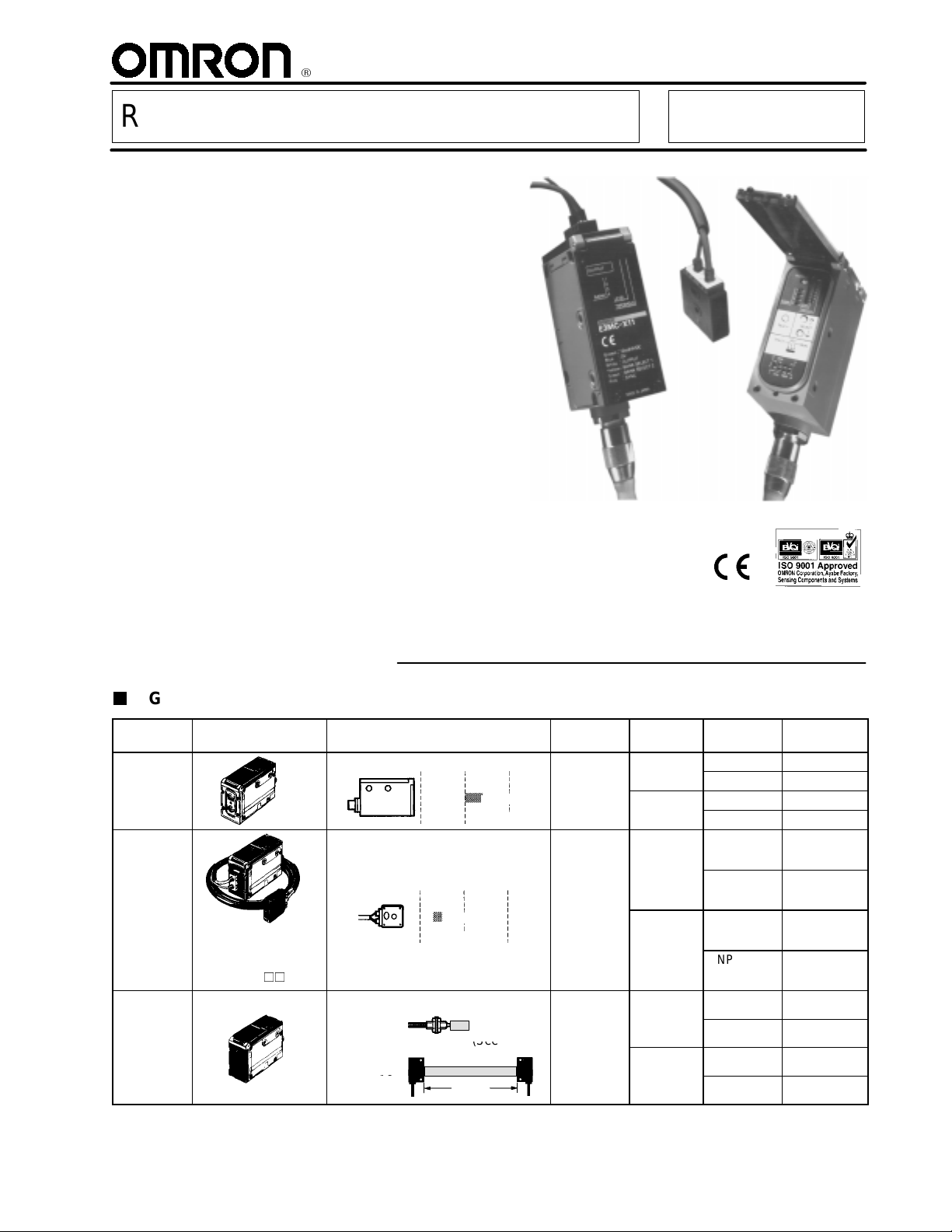
RGB Color Sensor E3MC
RGB Color Sensor Detects Subtle
Color Differences—Most Advanced
Color Sensor In the Industry
LED light source insures ease of
operation and long life
No separate light source is required
Remote control of color setting from PC
or PLC
4-color memory
4-output models available
3 models: lensed, precision fiber-optic,
versatile standard fiber-optic
IP66
Rugged die-cast metal housing
Ordering Information
RGB COLOR SENSOR
Type Appearance Sensing distance Spot
Lensed
Precision
fiber-optic
p
Generalpurpose
fiber-optic
pe
t
The shape of the
p
amp
er sectionis
thesameasforthe
E3MC-(M)A.
E32-CC200
E32-T16
0 50 100
60±10 mm
(See Note.)
0 50 100
20±4mm
(See Note.)
Standard sensing distance
5mm
SeeNote2.
200 mm
diameter
12 mm 1
3mm 1
Varies with
the recommended
fiber.
No. of
outputs
4
4
1
-
.
4
Output Part number
NPN E3MC-A11
PNP E3MC-A41
NPN E3MC-MA11
PNP E3MC-MA41
NPN E3MC-X11
PNP E3MC-X41
NPN E3MC-MX11
PNP E3MC-MX41
NPN E3MC-Y11
PNP E3MC-Y41
NPN E3MC-MY11
PNP E3MC-MY41
Note: Refer to the
Specifications
section of this data sheet.
E3MC
y
f
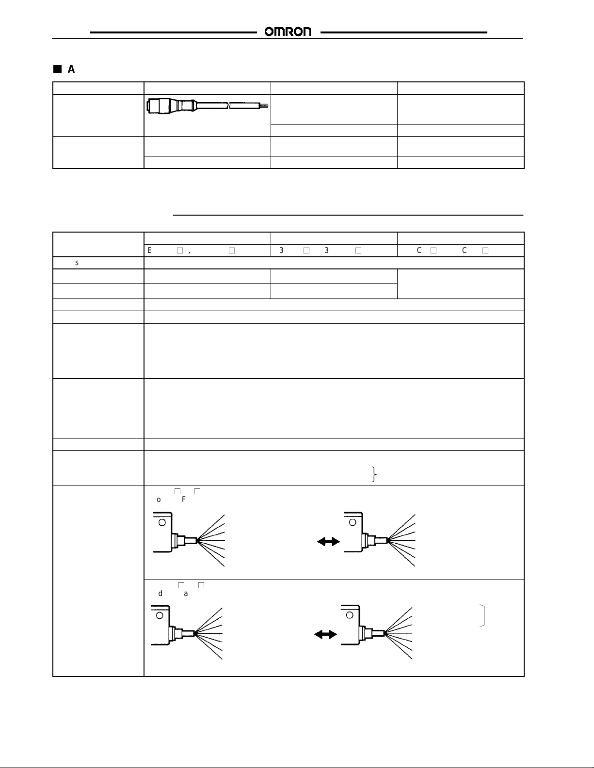
ACCESSORIES (ORDER SEPARATELY)
E3MC
Item Appearance Description
Sensor cable (2-m
Replacement cable
Part number (length)
E39-C1 (2M)
cable is included with
the E3MC)
E39-C1 (5M)
E39-L114
Mounting bracket
5-meter cable
-- -- -- Used for die-cast body mounting
(See Note.)
-- -- -- Used for DIN-rail mounting
E39-L115
Note: Included with sensor.
Specifications
Type
Light source Red (680 nm), green (525 nm), and blue (450 nm) LEDs
Sensing distance 60±10 mm 20±4mm
Spot diameter 12 dia. 3dia.
Supply voltage 12 to 24 VDC±10%, ripple (p-p) 10% max.
Current consumption 100 mA max.
Output Load current: 100 mA max.
Response time 1-output model:
Timer function 40-ms OFF-delay timer (ON/OFF switch selectable)
Color detection Four colors stored in teaching operation with manual threshold level adjustments.
Color detection mode
Mode selection
Lensed Precision fiber-optic type General-purpose fiber-optic type
E3MC-A1, E3MC-MA1 E3MC-X1, E3MC-MX1 E3MC-Y1, E3MC-MY1
Varies with the recommended
iber. Refer to Engineering Data
for details.
NPN open collector output with a maximum residual voltage of 1.2 V for the E3MC-(M)A11, E3MC-(M)X11,
and E3MC-(M)Y11.
PNP open collector output with a maximum residual voltage of 2.0 V for the E3MC-(M)A41, E3MC-(M)X41,
and E3MC-(M)Y41.
L.O./D.O., switch selectable
Standard mode: 3 ms max.
High-speed mode: 1 ms max. (switch selectable)
4-output model:
Standard mode: 6 ms max.
High-speed mode: 2 ms max. (switch selectable)
Mode C: RGB ratio detection; adapts to changes in conditions
Mode I: RGB light intensity detection; highest precision
Switch selectable
E3MC-11/-41
Mode A (Factory-set) Mode B (for remote teaching)
Output (white)
Not used (gray)
Bank selection input1 (yellow)
Bank selection input 2 (green)
External synchronous input(pink)
VCC(brown)
0 V (blue)
E3MC-M11/-M41
Mode A (Factory-set)
Colors in parenthesesare lead wire colors.
Output 1 (white)
Output 2 (gray)
Output 3 (yellow)
Output 4 (green)
External synchronous input(pink)
VCC(brown)
0 V (blue)
Colors in parenthesesare lead wire colors.
(This table continueson the next page.)
Mode B (for remote teaching)
Colors in parenthesesare lead wire colors.
Colors in parenthesesare lead wire colors.
Output (white)
Answer-back output (gray)
Remote control input(yellow)
Not used (green)
External synchronous input(pink)
VCC(brown)
0 V (blue)
Output 1 (white)
Output 2 (gray)
Output 3 (yellow)
Answer-back output (green)
Remote control input(pink)
VCC(brown)
0 V (blue)
3 outputs
E3MC
y
E3MC
Specifications Table
Type
-- continued from previous page
Lensed Precision fiber-optic type General-purpose fiber-optic type
E3MC-A1, E3MC-MA1 E3MC-X1, E3MC-MX1 E3MC-Y1, E3MC-MY1
Remote control input
(See Note 1.)
The following control is performed according to the control signal input.
E3MC-11/-41
Bank selection, remote teaching, or threshold selection
(mode B only)
Answer-back output
E3MC-M11/-M41
Channel selection, remote teaching, or threshold selection
Load current: 100 mA max.
NPN open collector output with a residual voltage of 1.2 V max.
E3MC-(M)A11/-(M)X11/-(M)Y11
PNP open collector output with a residual voltage of 2.0 V max.
(mode B only)
External synchronous
Response time: 1 ms max. (The 4-output model is not available in mode B.)
E3MC-(M)A41/-(M)X41/-(M)Y41
input
Color detection 4 banks selectable (either by bank selection input or by using the SELECT button)
Input response time for bank selection: 50 ms max.
Indicator Operation indicator (orange LED), 4-level bank indicator (green LED, See Note 3.), 7-level threshold
indicator (red LED), 8-level detection indicator (green LED), and four channel indicators (orange LED, See
Note 4.)
Protection Protection from reversed power supply connection and output short-circuit
Ambient light immunity
Incandescent lamp: Illumination on optical spot: 3,000xmax.
Sunlight: Illumination on optical spot: 10,000xmax.
Ambient temperature Operating: --25°Cto55°C(--13°F to 131°F) with no icing
Relative humidity Operating: 35% to 85% (with no condensation)
Permissible fiber
bending radius
--- 10 mm min. Varies with the type of selected
fiber (see specific fiber
specifications)
Insulation resistance 20 MΩmin. (at 500 VDC)
Dielectric strength 1,000 VAC, 50/60 Hz for 1 min
Vibration resistance 10 to 55 Hz, 1.0-mm double amplitude or 150 m/s2(approx. 15G) for 2 hrs each in X, Y, and Z axis.
0.75-mm double amplitude or 100 m/s
Shock resistance 500 m/s2(approx. 50G) for 3 times each in X, Y, and Z axis.
300 m/s
2
(30G) when using a Mounting Bracket.
2
(10G) when using a Mounting Bracket.
Enclosure rating IEC IP66 (with protective cover in place)
Material Case: Zinc die-cast
Cover: PES
Case: Zinc die-cast
Cover: PES
Case: Zinc die-cast
Cover: PES
Fiber head: ABS
Weight (with 2-m cable) Approx. 350 g Approx. 400 g Approx. 350 g
Note: 1. Refer to
Remote Teaching
.
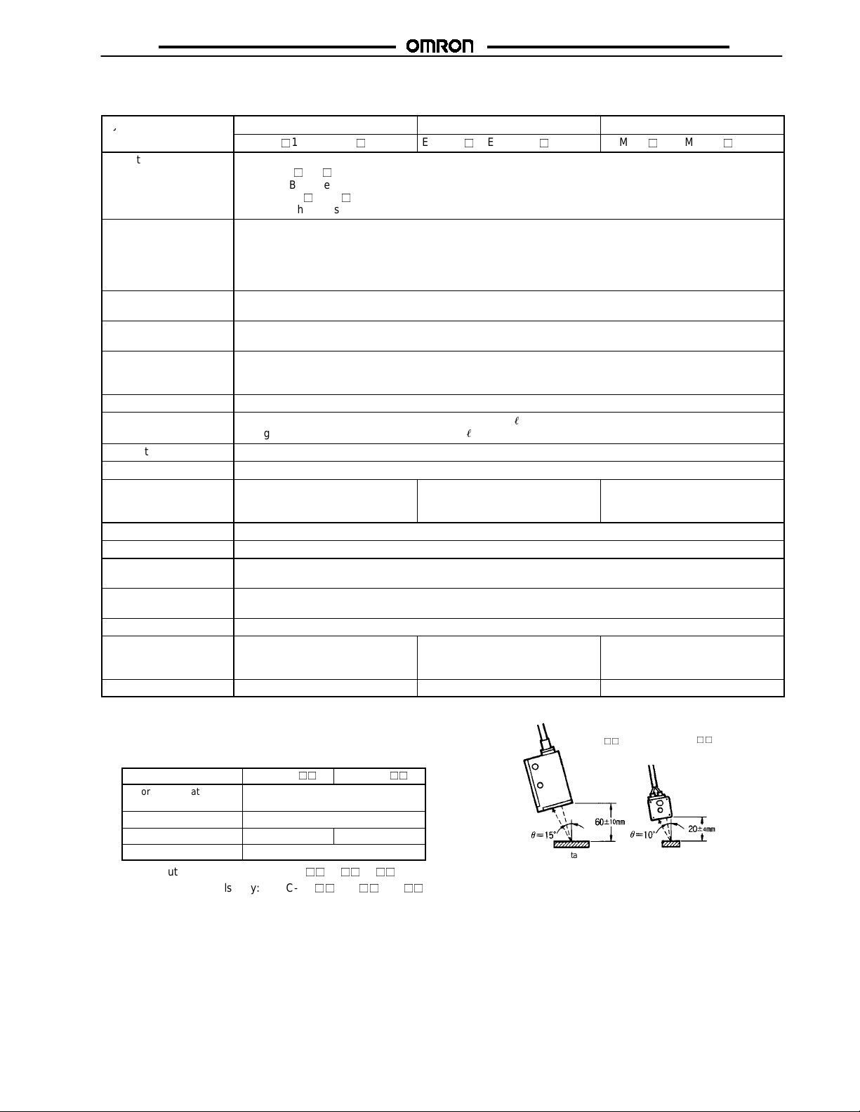
2. Definition of Sensing Distance
Refer to the following table and the diagram to the
right.
Item
Color discrimination
mode
Response time Standard mode
Tolerance (θ) 15
Detectable colors 11 standard colors
3. 1-output models only: E3MC-A/-X/-Y
E3MC-(M)A
Mode C
°
E3MC-(M)X
°
10
4. 4-output models only: E3MC-MA/-MX/-MY
E3MC-(M)A
Sensing target
E3MC-(M)X
Fiber Head
Sensing target
E3MC
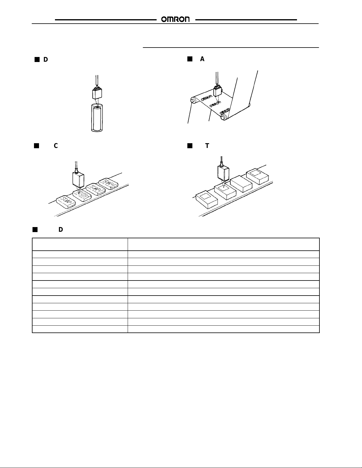
Application Examples
DETECTING INTERNAL YELLOW
RESIN PLATES OF A BATTERY
PATTERN POSITIONING
E3MC
DISCRIMINATING FRONT AND BACK
SIDES OF OBJECTS
STANDARD SENSING OBJECTS
Color
(11standard colors)
White N9.5
Red 4R 4.5/12.0
Yellow/red 4YR 6.0/11.5
Yellow 5Y 8.5/11.0
Yellow/green 3GY 6.5/10.0
Green 3G 6.5/9.0
Blue/green 5BG 4.5/10.0
Blue 3PB 5.0/10.0
Blue/purple 9PB 5.0/10.0
Purple 7P 5.0/10.0
Red/purple 6RP 4.5/12.5
Munsell color notation (See Note.)
DETECTING LABELS
Note: Munsell Color Notation: A color classification system that assigns three values to each color: Hue, Value, and Chroma. System
was developed by Albert Munsell and published in 1905.
E3MC
EngineeringData
E3MC
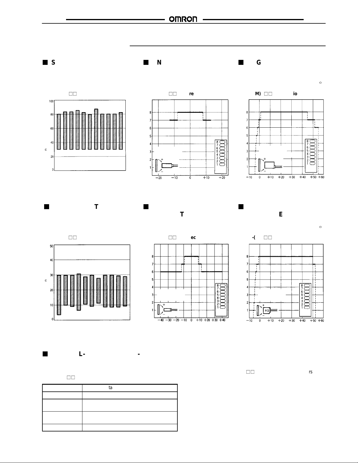
SENSING DISTANCE VS.
COLOR DIFFERENCES
(TYPICAL)
Sensing distance(mm)
Red
White
SENSING DISTANCE VS.
Yellow
Yellow/red
Yellow/green
Green
Blue
Blue/green
COLOR DIFFERENCES
(TYPICAL)
E3MC-(M)X
ANGLE
CHARACTERISTICS
(TYPICAL)
ANGLE
CHARACTERISTICS
(WHEN TEACHING AT
AN INCLINATION OF 15)
E3MC-(M)A(X Direction)E3MC-(M)A
Detection level
Sensing target:
Blue/Green
30 x 27mm
Detection
level
Purple
Red/purple
Blue/purple
ANGLE
Angle (°) Angle (°)
CHARACTERISTICS
(TYPICAL)
E3MC-(M)A(Y Direction)
Detection level
Sensing target:
Blue/Green
30 x 27mm
ANGLE
CHARACTERISTICS
(WHEN TEACHING AT
Detection
level
AN INCLINATION OF 10)
E3MC-(M)X(X Direction) E3MC-(M)X(Y Direction)
Sensing target:
Detection level
Blue/Green
Sensing distance(mm)
Red
White
GENERAL-PURPOSE FIBER-OPTIC TYPE
Yellow
Yellow/red
Yellow/green
Green
Blue
Blue/green
Purple
Red/purple
Blue/purple
30 x 27mm
Recommended Fiber: Diffuse Fiber-Optic
The following optical fibers are recommended for use with the
E3MC-(M)Y.
Part number
E32-DC200 5mm
E32-CC200
(See Note 2.)
E32-D32L
(See Note 3.)
E32-D11L 5mm
Sensing distance (See Note 1.)
5mm
4.5 mm
Sensing target
Blue/Green
Detection level
30 x 27mm
Detection
level
Angle (°) Angle (°)
Detection
level
Note: 1. The E3MC-(M)Ydiscriminates eleven colors at the
above distances. For a typical example, nine colors are
discriminated at a sensing distance of 12 mm.
2. The fiber to be inserted into the emitter is indicated
with white lines. Insert the amplifier fiber into the lower
emitter section.
3. The fiber to be inserted into the emitter is indicated
with dotted yellow lines. Insert the amplifier fiber into
the lower emitter section.
E3MC
g
t
ical
characteristics
t
ical
characteristics
E3MC
Sensing Distance of a Diffuse Fiber
E32-DC200, etc.
Sensing distance
Sensing target
AVAILABLE OPTICAL FIBERS
In addition to the previous recommended optical fibers, the following optical fibers are available for the E3MC-(M)Y. Refer to the
E3X-NH Datasheet (E258-E1)
Part number
E32-TC200A
E32-TC200B
E32-TC200C
E32-TC200D
E32-T12L Not different from
E32-T14
E32-T11
E32-T11R Through-beam
for the following optical fibers in detail. Optical fibers other than the following are not available.
Sensing method Remarks
Through-beam Not different from
(R1 fiber)
the E32-TC200 in
p
op
characteristics.
the E32-T11L in
optical
characteristics.
---
---
.
RECOMMENDED FIBER: THROUGH-
BEAM FIBER
The following optical fibers are recommended for use with the
E3MC-(M)Y.
Part number
E32-TC200 30 mm
E32-T11L 60 mm
E32-T16 200 mm
E32-T17L 1.1 m
Note: The E3MC-(M)Ydiscriminates red, blue, and yellow
films at the above distances.
Part number Sensing method Remarks
E32-DC200B
E32-DC200C
E32-DC200D
E32-D12
E32-D11
E32-D11R Through-beam
E32-G14 Groove ---
Sensing range (See Note.)
Diffuse Not different from
(R1 fiber)
the E32-DC200 in
p
op
characteristics.
---
.
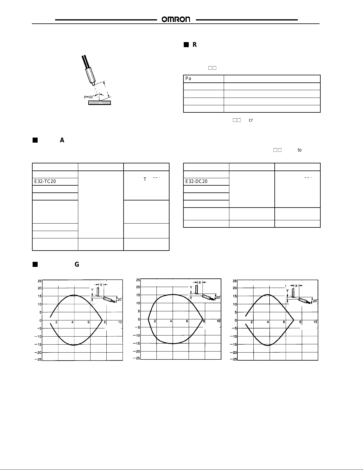
OPERATING RANGE CHARACTERISTICS (TYPICAL)
E32-DC200 E32-CC200
Sensing target: Blue/Green38 x 38 mm
Distance Y (mm)
Distance X (mm) Distance X (mm) Distance X (mm)
Sensing target: Blue/Green
38 x 38mm
Distance Y (mm)
E32-D32L
Sensing target: Blue/Green38 x 38 mm
Distance Y (mm)
E3MC
E3MC
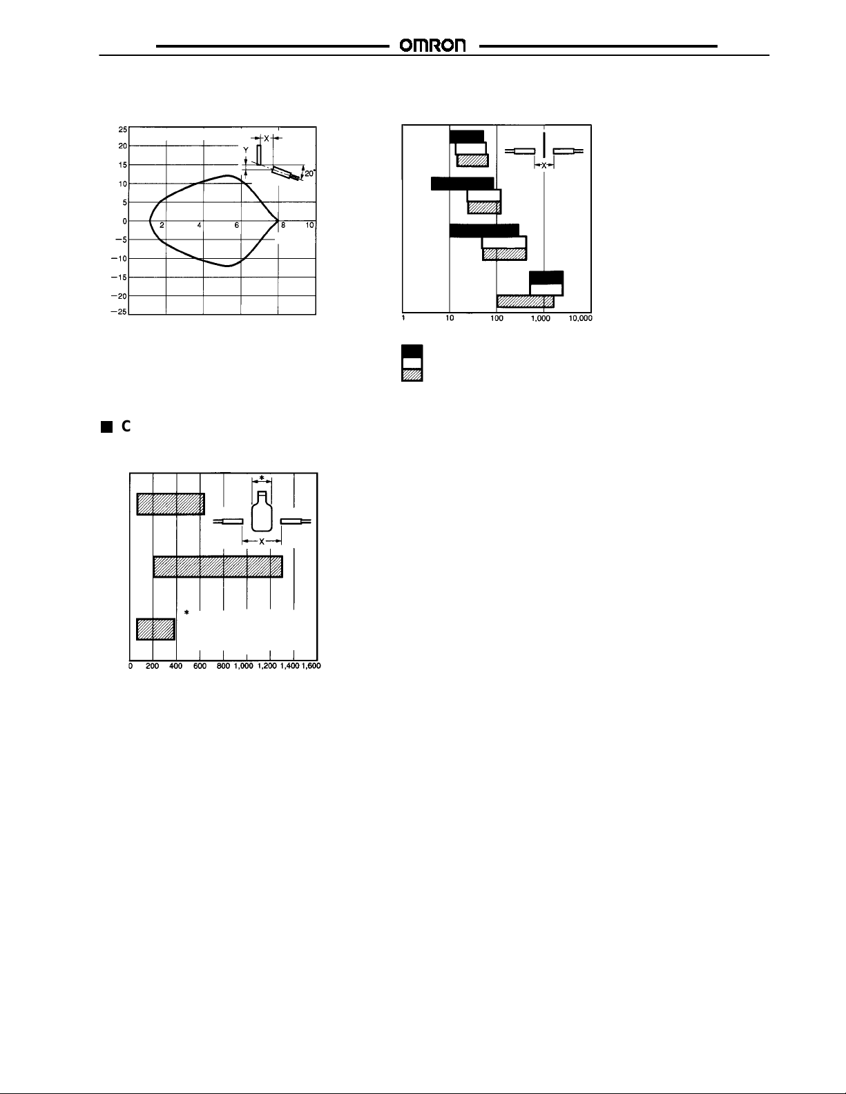
E32-D11L Sensing Target:
Red, Blue, and Yellow Films
Sensing target: Blue/Green38 x 38 mm
Distance Y (mm)
E32
-TC200
E32
-T11L
E32
-T16
E32
-T17L
Distance X (mm)
Sensing target: Filmin Red (rosco/UX, scarlet)
Sensing target: Film in Yellow (rosco/UX, straw)
Sensing target: Film inBlue (rosco/UX, skyblue)
The above colorfilms are made by the r osco company.
CHROMATIC SENSITIVITY (TYPICAL)
Sensing T arget: Bottle
E32-T17L
Distance X (mm)
Green
bottle
Brown
bottle
Darkbrown
bottle
Sensing target: 63-diagreen bottle
Sensing target: 60-diabrown bottle
Sensing target: 63-diadark-brown
bottle
Distance X (mm)
E3MC
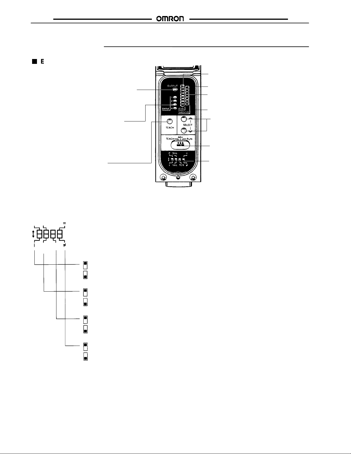
Nomenclature
E3MC ALL MODELS
Operation Indicator (Orange)
Illuminated when output is ON.
Under mode B (single-output
models), the indicator will be
illuminated when mode B is
active or when the mode selector is set to TEACH.
Bank Indicator (Green)
1-channel models. Displays
selected bank.
Channel Indicator (Orange)
4-channel models. Displays
selected channels. Illuminated
when the output of each channel
is ON.
TEACH Button
Stores target color. On 4-channel
models, used to check the number
of channels that are indicated by
both the operation indicator and
channel indicator.
E3MC
Detection Level Indicator (Green)
Displays similarity level between
registered and detectable colors.
Tolerance #1
Threshold Indicator (Red)
Displays threshold level.
Tolerance #7
SELECT UP Button, SELECT DOWN Button
Bank selection
Threshold adjustment
Mode Selector
Selects TEACH, ADJ, or RUN mode.
Function Switch (see details below)
Color discrimination mode selection
Response time selection
OFF-delay timer setting
Conformity/Non-conformity output selection
(See glossary—Light/Dark Operate)
Function Switch
The following settings are possible in RUN or ADJ mode. (Each pin of the function switch is factory-set to the upper position.)
(6 ms)
3ms
C
Note: Figures shown in parentheses are for the 4-output models.
1ms
TMR
(2 ms)
Color Discrimination Mode Selection (Mode C is Recommended for Normal Applications)
Mode C: Color discrimination is performed according to R (red), G (green), and B (blue) ratio of the reflection light even
if the sensing objects fluctuate up and down within the rated sensing range.
Mode I: Color discrimination is performed according to RGB light intensity of reflection light. This mode ensures more
delicate color discrimination than mode C.
Response Time Selection
3 ms (6 ms): The E3MC can stably detect minute differences of color. Set the response time to 3 ms for usual
1 ms (2 ms): The E3MC will be in quick-response operation. Set the response time to 1 ms if high-speed response is
OFF-delay Timer Setting
---: No OFF-delay timer is set.
TMR: A 40-ms OFF-delay timer is set for control output.
Conformity/Non-conformity Output (See glossary—Light/Dark Operate)
=: Output is ON when the detected color coincides with the registered color.
: Output is ON when the detected color does not coincide with the registered color.
≠
applications.
required.
 Loading...